Embed Size (px)
Citation preview
July, 2003 © 2003 by H.L. Bertoni 1
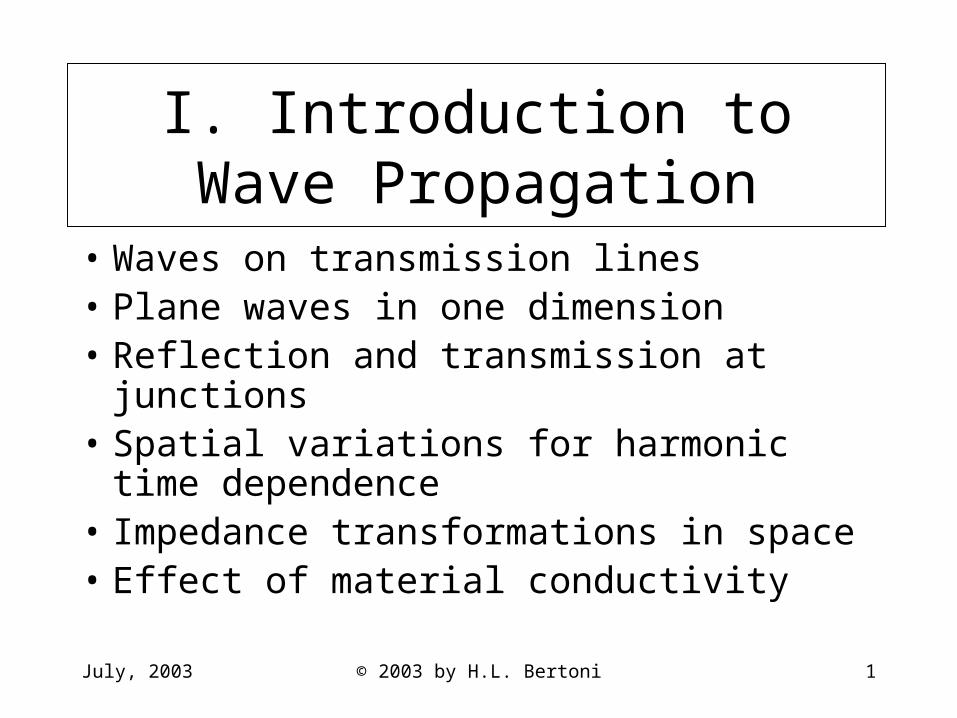
I. Introduction to Wave Propagation
• Waves on transmission lines• Plane waves in one dimension• Reflection and transmission at junctions• Spatial variations for harmonic time
dependence• Impedance transformations in space • Effect of material conductivity
July, 2003 © 2003 by H.L. Bertoni 2
Waves on Transmission Lines
• Equivalent circuits using distributed C and L• Characteristic wave solutions• Power flow

July, 2003 © 2003 by H.L. Bertoni 3
Examples of Transmission Lines
I(z,t) +
V(z,t) - z
I(z,t) +
V(z,t) -
Dielectric
Conductors
Strip Line
Coaxial Line
Two-Wire Line (Twisted Pair)

July, 2003 © 2003 by H.L. Bertoni 4
Properties of Transmission Lines (TL’s)
• Two wires having a uniform cross-section in one (z) dimension
• Electrical quantities consist of voltage V(z,t) and current I(z,t) that are functions of distance z along the line and time t
• Lines are characterized by distributed capacitance C and inductance L between the wires– C and L depend on the shape and size of the conductors
and the material between them

July, 2003 © 2003 by H.L. Bertoni 5
Capacitance of a Small Length of Line
€
The two wires act as a capacitor. Voltage applied to the wires
induces a charge on the wires, whose time derivative is the current.
Since the total charge, and hence the current, is proportional to
the length l of the wires. Let the constant of proportionality be
C Farads/meter. Then
I(t) =CldV(t)
dt
I(t) +
V(t) -
l
Open circuitE
July, 2003 © 2003 by H.L. Bertoni 6
Inductance of a Small Length of Line
€
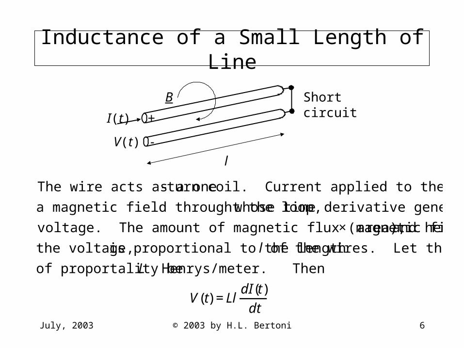
The wire acts as a one- turn coil. Current applied to the wires induces
a magnetic field throught the loop, whose time derivative generates the
voltage. The amount of magnetic flux (magnetic field × area), and hence
the voltage, is proportional to the length l of the wires. Let the constant
of proportality be L Henrys/meter. Then
V(t) =LldI(t)dt
I(t) +
V(t) -
l
Short circuitB

July, 2003 © 2003 by H.L. Bertoni 7
C and L for an Air Filled Coaxial Line
a
b
€
C =2πεo
ln b a( ) L =
μo
2πln b a( )
Permittivity of vacuum: εo ≈10−9
36π Farads/m
Permeability of vacuum: μo ≡4π ×10−7 Henrys/m
€
Suppose that a=0.5 mm and b=2 mm. Then
C =2πεo
ln4=40.1 pF/m and L =
μoln42π
=0.277 μH/m
Note that
1LC
=1
μoεo
=3×10⁸ m/s and LC
=ln b a( )
2πμo
εo
=ln42π
377=83.2 Ω
July, 2003 © 2003 by H.L. Bertoni 8
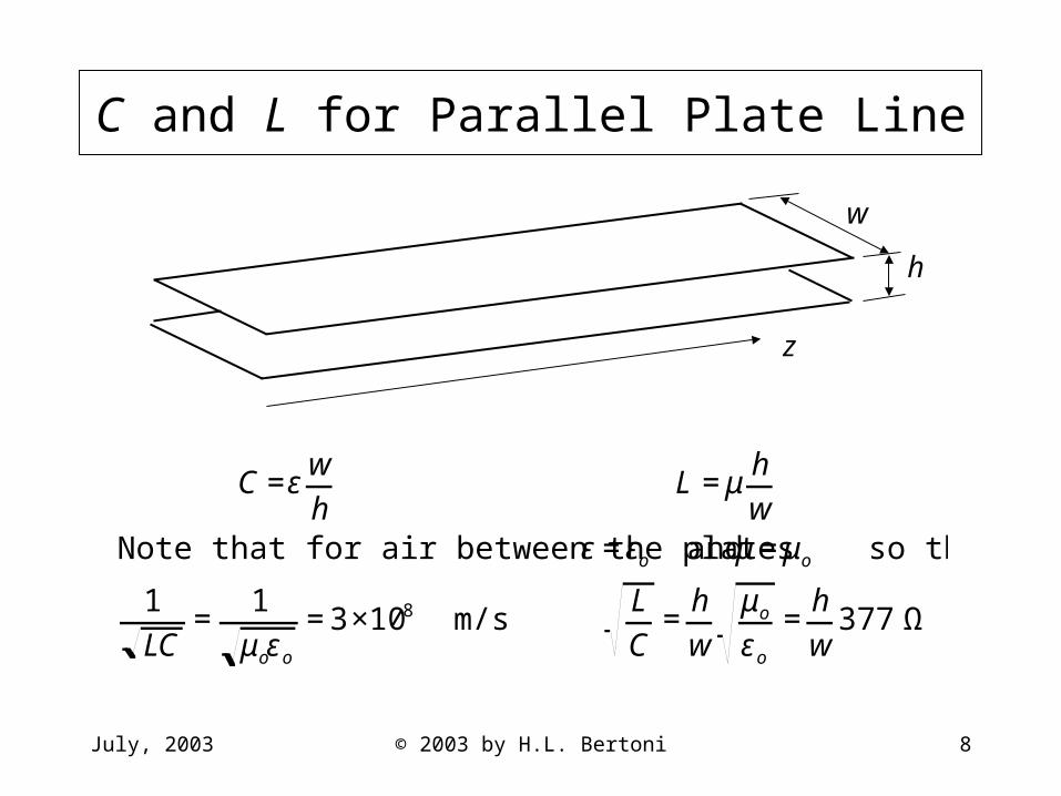
C and L for Parallel Plate Line
w
h
z
€
C =εwh
L =μhw
Note that for air between the plates ε=εo and μ=μo so that
1LC
=1
μoεo
=3×10⁸ m/s LC
=hw
μo
εo
=hw
377 Ω
July, 2003 © 2003 by H.L. Bertoni 9
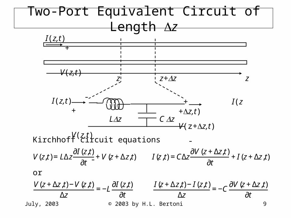
Two-Port Equivalent Circuit of Length zI(z,t) +
V(z,t)
-z z+z z
Lz C z
I(z,t) +
V(z,t)
-
+ I(z +z,t)
V(z+z,t)
-
€
Kirchhoff circuit equations
V(z,t)=LΔz∂I (z,t)
∂t+V(z+Δz,t) I (z,t) =CΔz
∂V(z+Δz,t)∂t
+I (z+Δz,t)
or
V(z+Δz,t)−V(z,t)Δz
=−L∂I (z,t)
∂t
I (z+Δz,t)−I (z,t)Δz
=−C∂V(z+Δz,t)
∂t
July, 2003 © 2003 by H.L. Bertoni 10
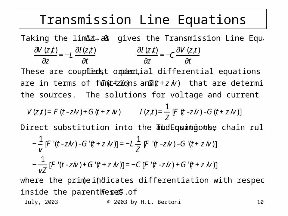
Transmission Line Equations
€
Taking the limit as Δz→ 0 gives the Transmission Line Equations
∂V(z,t)
∂z=−L
∂I(z,t)∂t
∂I (z,t)
∂z=−C
∂V(z,t)∂t
These are coupled, first order, partial differential equations whose solutions
are in terms of functions F(t- z/v) and G(t+z/v) that are determined by
the sources. The solutions for voltage and current are of the form
V(z,t)=F(t- z/v)+G(t+z/v) I (z,t)=1Z
F (t-z/v)-G(t+z/v)[ ]
Direct substitution into the TL Equations, and using the chain rule gives
−1v
F '(t- z/v)-G'(t+z/v)[ ] =−L1Z
F '(t-z/v)-G'(t+z/v)[ ]
−1vZ
F '(t- z/v)+G'(t+z/v)[ ]=−C F '(t-z/v) +G'(t+z/v)[ ]
where the prime (' ) indicates differentiation with respect to the total variable
inside the parentheses of F or G.
July, 2003 © 2003 by H.L. Bertoni 11
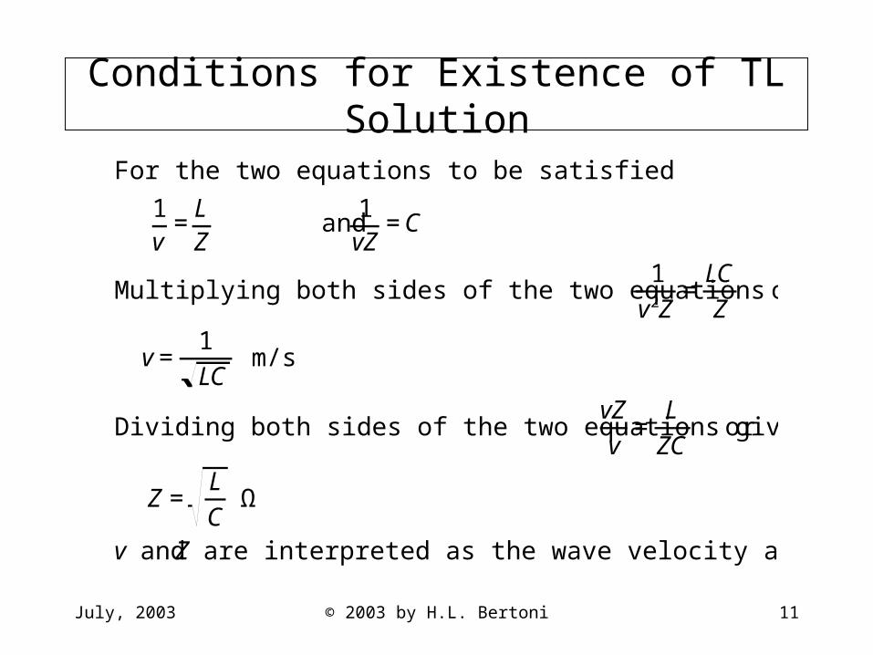
Conditions for Existence of TL Solution
€
For the two equations to be satisfied
1v
=LZ
and 1vZ
=C
Multiplying both sides of the two equations gives 1
v2Z=
LCZ
or
v=1LC
m/s
Dividing both sides of the two equations gives vZv
=L
ZC or
Z=LC
Ω
v and Z are interpreted as the wave velocity and wave impedance.

July, 2003 © 2003 by H.L. Bertoni 12
F(t-z/v) Is a Wave Traveling in +z Direction
€
Assume that G(t+z/v)=0
Then the voltage and current are
V(z,t)=F(t−z/v)=F (−1 v)(z−vt)[ ]
I(z,t)=1Z
F(t−z/v)=1Z
F (−1 v)(z−vt)[ ]
F(t−z/v) represents a wave disturbance
traveling in the positive z direction with
velocity v.
Note that the current in the conductor at
positive potential flows in the direction of
wave propagation.
V(z,0)=F[(-1/v)(z)]
V(z,t)=F[(-1/v)(z-vt)]
a z
-a
a+vt z
-a+vt
vt
t = 0
t > 0
July, 2003 © 2003 by H.L. Bertoni 13
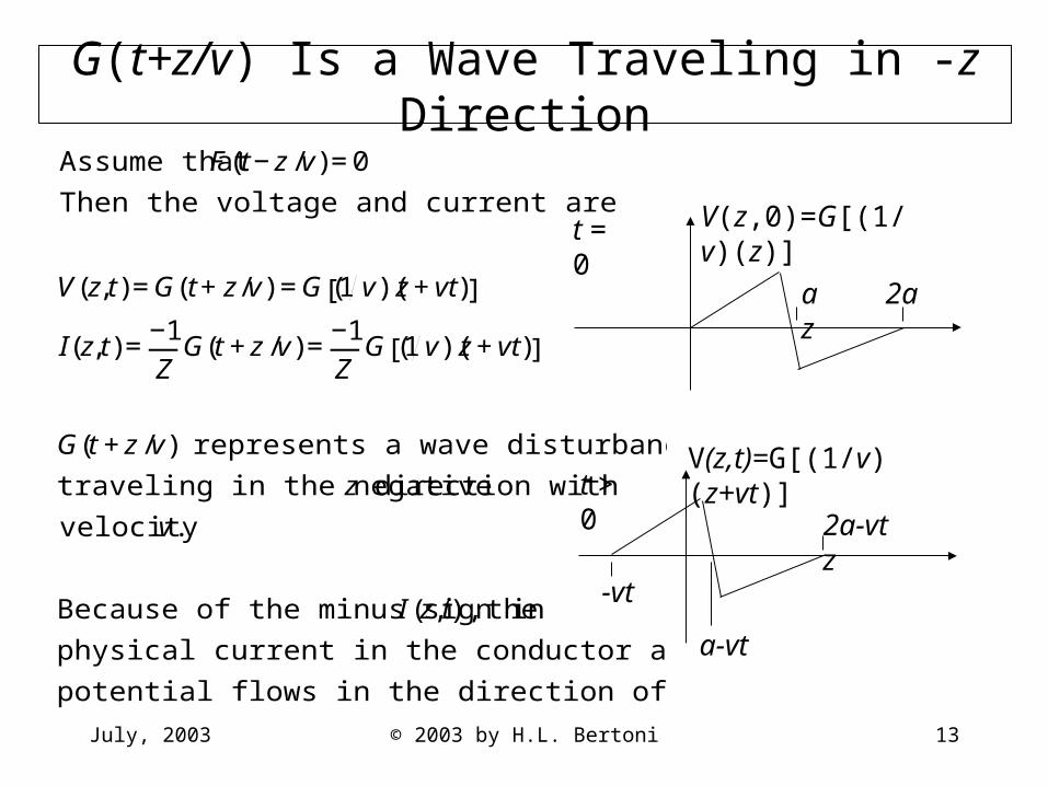
G(t+z/v) Is a Wave Traveling in -z Direction
€
Assume that F(t−z/v)=0
Then the voltage and current are
V(z,t)=G(t+z/v) =G (1 v)(z+vt)[ ]
I(z,t)=−1Z
G(t+z/v)=−1Z
G (1v)(z+vt)[ ]
G(t+z/v) represents a wave disturbance
traveling in the negative z direction with
velocity v.
Because of the minus sign in I (z,t), the
physical current in the conductor at positive
potential flows in the direction of wave propagation.
V(z,0)=G[(1/v)(z)]
a 2a z
t = 0
V(z,t)=G[(1/v)(z+vt)]
2a-vt z
-vt
a-vt
t > 0
July, 2003 © 2003 by H.L. Bertoni 14
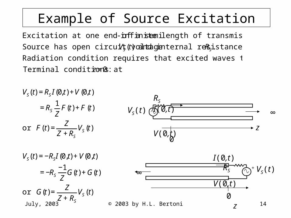
Example of Source Excitation
€
Excitation at one end of a semi- infinite length of transmission line.
Source has open circuit voltage VS(t) and internal resistance RS.
Radiation condition requires that excited waves travel away from source.
Terminal conditions at z=0:
VS(t) =RSI (0,t)+V(0,t)
=RS1Z
F(t)+F (t)
or F(t) =Z
Z+RS
VS(t)
VS(t) =−RSI (0,t)+V(0,t)
=−RS
−1Z
G(t)+G(t)
or G(t)=Z
Z+RS
VS(t)
∞
z
VS(t) +
0
RS I(0,t)
V(0,t)
+ VS(t)
I(0,t) RS
V(0,t)
0 z
∞
July, 2003 © 2003 by H.L. Bertoni 15
Receive Voltage Further Along Line
+ VS(t)
∞
z
VS(t) +
0 l
RS
V(l,t)
Scope
RS
V(-l,t)
-l 0 z
∞
Scope
€
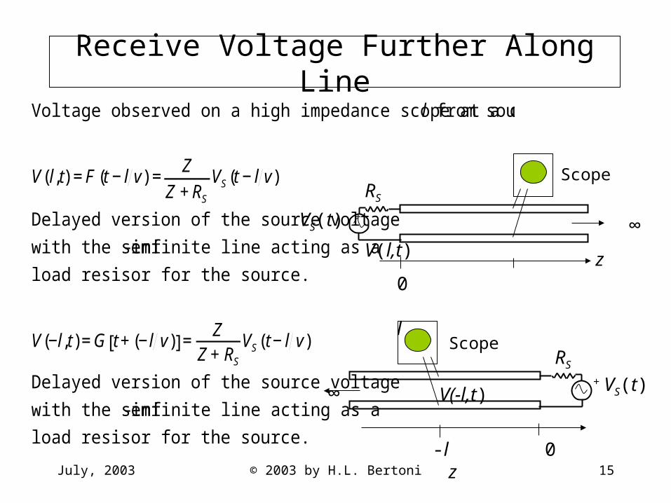
Voltage observed on a high impedance scope at a distance l from source.
V(l,t) =F (t−l v) =Z
Z+RS
VS(t−l v)
Delayed version of the source voltage
with the semi- infinite line acting as a
load resisor for the source.
V(−l,t)=G t+(−l v)[ ]=Z
Z+RS
VS(t−l v)
Delayed version of the source voltage
with the semi- infinite line acting as a
load resisor for the source.
July, 2003 © 2003 by H.L. Bertoni 16
Power Carried by Waves
P(z,t)
I(z,t)
V(z,t)
z
€
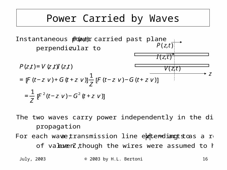
Instantaneous power P(z,t) carried past plane
perpendicular to z.
P(z,t)=V(z,t)I (z,t)
= F(t−z v)+G(t+z v)[ ]1Z
F(t−z v)−G(t+z v)[ ]
=1Z
F 2(t−z v)−G2(t+z v)[ ]
The two waves carry power independently in the direction of wave
propagation
For each wave, a transmission line extending to z→ ∞ acts as a resistor
of value Z, even though the wires were assumed to have no resistance.
July, 2003 © 2003 by H.L. Bertoni 17
Summary of Solutions for TL’s
• Solutions for V and I consists of the sum of the voltages and current of two waves propagating in ±z directions
• For either wave, the physical current flows in the direction of propagation in the positive wire
• Semi-infinite segment of TL appears at its terminals as a resistance of value Z (even though the wires are assumed to have no resistance)
• The waves carry power independently in the direction of wave propagation
July, 2003 © 2003 by H.L. Bertoni 18
Plane Waves in One Dimension
• Electric and magnetic fields in terms of voltage and current
• Maxwell’s equations for 1-D propagation• Plane wave solutions• Power and polarization
July, 2003 © 2003 by H.L. Bertoni 19
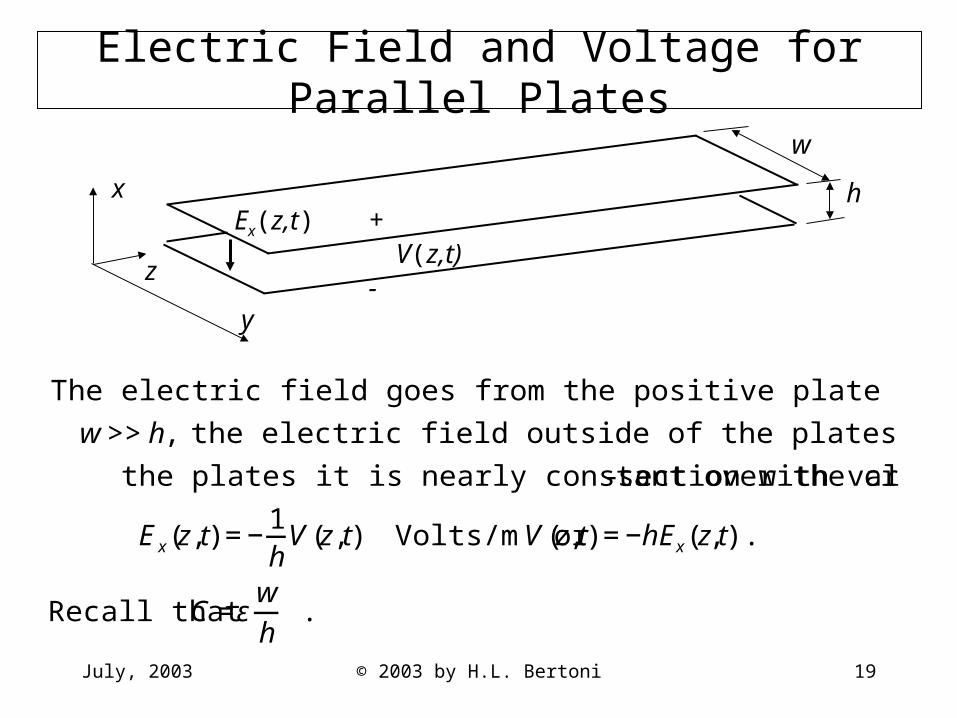
Electric Field and Voltage for Parallel Plates
€
The electric field goes from the positive plate to the negative plate. If
w>>h, the electric field outside of the plates is very small. Between
the plates it is nearly constant over the cross-section with value
Ex(z,t) =−1h
V(z,t) Volts/m or V(z,t) =−hEx(z,t).
Recall that C =εwh
.
w
h
z
y
Ex(z,t) + V(z,t)-
x
July, 2003 © 2003 by H.L. Bertoni 20
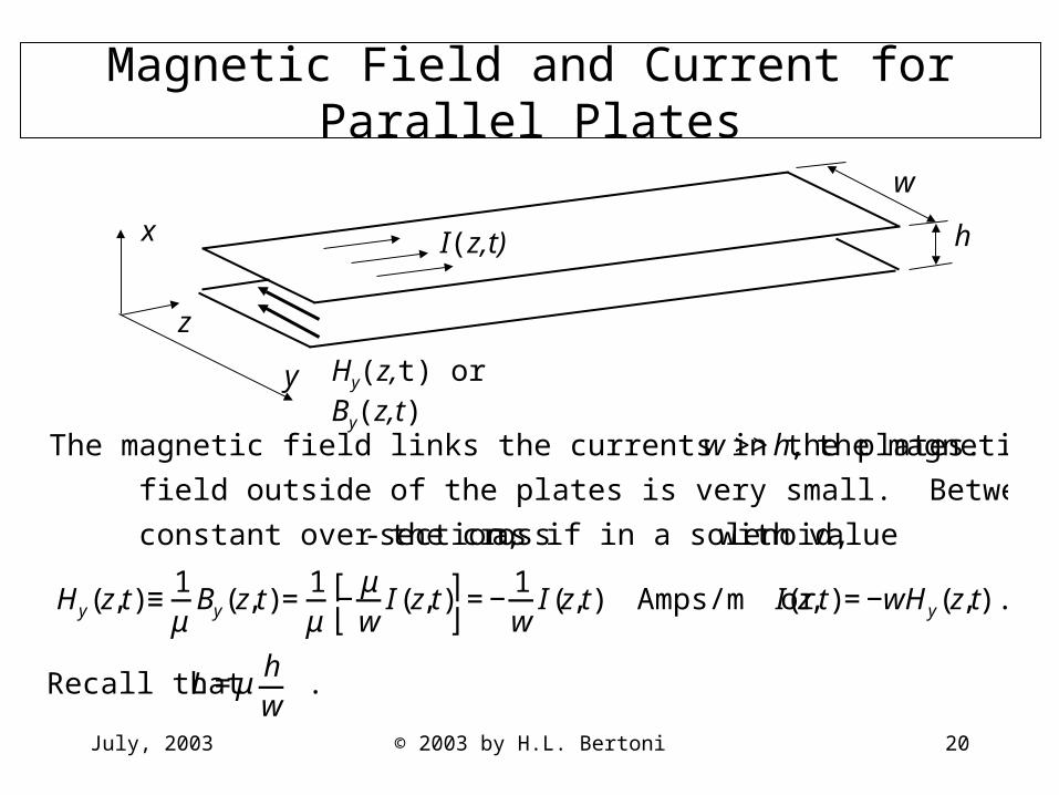
Magnetic Field and Current for Parallel Plates
w
h
z
y Hy(z,t) or By(z,t)
I(z,t)x
€
The magnetic field links the currents in the plates. If w >>h, the magnetic
field outside of the plates is very small. Between the plates it is nearly
constant over the cross-section, as if in a solenoid, with value
Hy(z,t)≡1μ
By(z,t)=1μ
−μw
I (z,t)⎡ ⎣
⎤ ⎦ =−
1w
I (z,t) Amps/m or I(z,t)=−wHy(z,t).
Recall that L =μhw
.

July, 2003 © 2003 by H.L. Bertoni 21
Maxwell’s Equations in 1-D
€
Inserting the foregoing expressions for V(z,t), C, I (z,t) and L into the
Transmission Line equations
∂∂z
−hEx(z,t)[ ]=−μhw
⎡ ⎣
⎤ ⎦ ∂∂t
−wHy(z,t)[ ] ∂∂z
−wHy(z,t)[ ] =−εwh
⎡ ⎣
⎤ ⎦ ∂∂t
−hEx(z,t)[ ]
or
∂∂z
Ex(z,t) =−μ∂∂t
Hy(z,t) ∂∂z
Hy(z,t)=−ε∂∂t
Ex(z,t)
These are the two Maxwell equations for linearly polarized wave propagating in
1-D. They are independent of (h,w) and refer to the fields.
We may think of the plates as being taken to (x,y) → ∞ so they need not be
considered.
The field are in the form of a plane wave, which covers all space and is a simple
approximation for fields in a limited region of space, such as a laser beam.
July, 2003 © 2003 by H.L. Bertoni 22
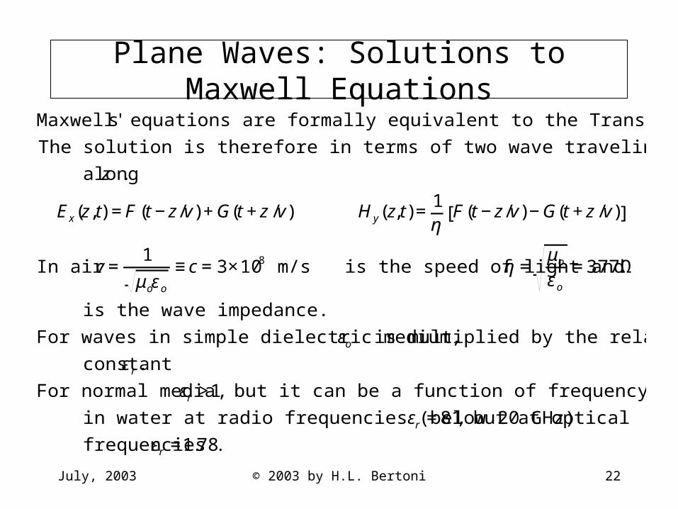
Plane Waves: Solutions to Maxwell Equations
€
Maxwell's equations are formally equivalent to the Transmission Line Equations
The solution is therefore in terms of two wave traveling in opposite directions
along z .
Ex(z,t) =F (t−z/v)+G(t+z/v) Hy(z,t)=1η
F(t−z/v)−G(t+z/v)[ ]
In air v=1
μoεo
≡c=3×10⁸ m/s is the speed of light and η =μo
εo
=377 Ω
is the wave impedance.
For waves in simple dielectric medium, εo is multiplied by the relative dielectric
constant εr.
For normal media εr >1, but it can be a function of frequency. As and example,
in water at radio frequencies (below 20 GHz) εr =81, but at optical
frequencies εr =1.78.
July, 2003 © 2003 by H.L. Bertoni 23
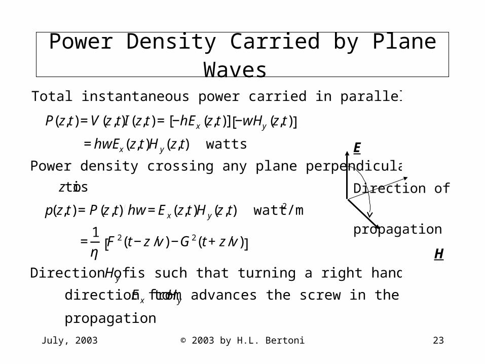
Power Density Carried by Plane Waves
€
Total instantaneous power carried in parallel plate line
P(z,t)=V(z,t)I (z,t)= −hEx(z,t)[ ] −wHy(z,t)[ ]
=hwEx(z,t)Hy(z,t) watts
Power density crossing any plane perpendicular
to z is
p(z,t)=P(z,t) hw=Ex(z,t)Hy(z,t) watt/m2
=1η
F 2(t−z/v)−G2(t+z/v)[ ]
Direction of Hy is such that turning a right hand screw in the
direction from Ex to Hy advances the screw in the direction of
propagation
E
Direction of
propagation
H
July, 2003 © 2003 by H.L. Bertoni 24
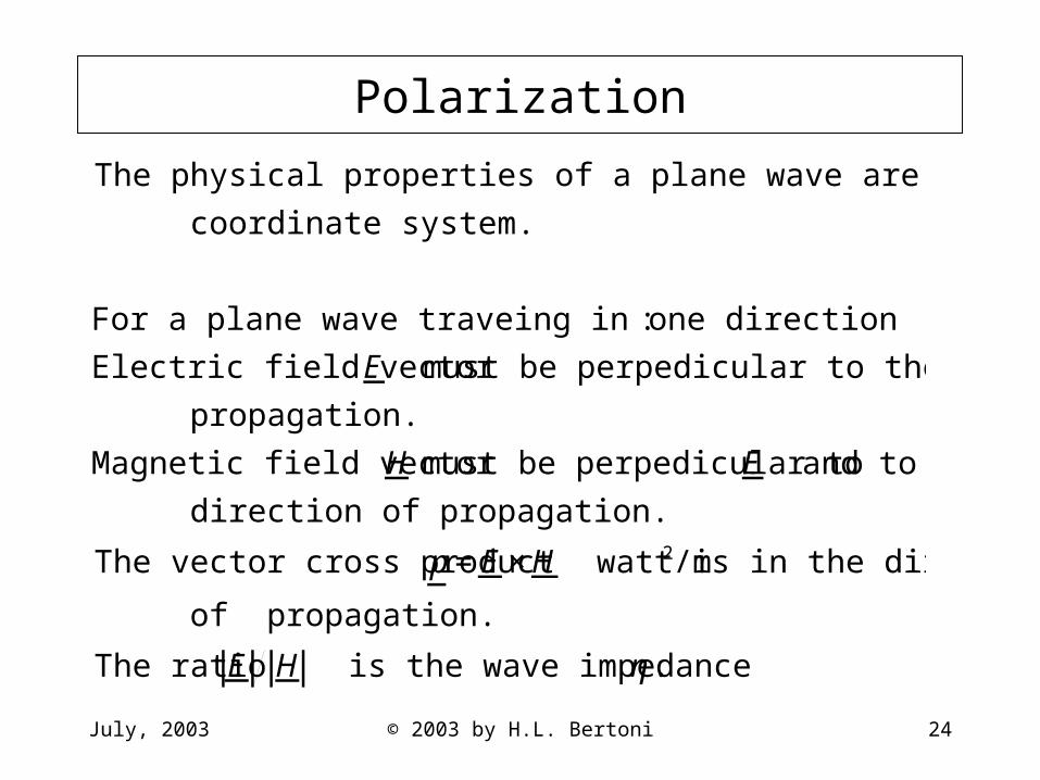
Polarization
€
The physical properties of a plane wave are independent of the
coordinate system.
For a plane wave traveing in one direction:
Electric field vector E must be perpedicular to the direction of
propagation.
Magnetic field vector H must be perpedicular to E and to the
direction of propagation.
The vector cross product p=E ×H watt/m2 is in the direction
of propagation.
The ratio E H is the wave impedance η.

July, 2003 © 2003 by H.L. Bertoni 25
Examples of Polarization
€
Linear polaization of E along x Linear polaization of E along y
E =axcosω(t−z/v)[ ] E =aysinω(t−z/v)[ ]
H =ay1η
cosω(t−z/v)[ ] H =−ax1η
sinω(t−z/v)[ ]
€
Circular polarization
E =axcosω(t−z/v)[ ]+aysinω(t−z/v)[ ]
H =1η
aycosω(t−z/v)[ ]−ax sinω(t−z/v)[ ]{ }
E
x z
H
y
x z
E
y H
€
ax = unit vector along x
ay = unit vector along y
July, 2003 © 2003 by H.L. Bertoni 26
Summary of Plane Waves
• Plane waves are polarized with fields E and H perpendicular to each other and to the direction of propagation
• Wave velocity is the speed of light in the medium• ExH watts/m2 is the power density carried by a
plane wave

July, 2003 © 2003 by H.L. Bertoni 27
Reflection and Transmission at Junctions
• Junctions between different propagation media• Reflection and transmission coefficients for 1-D
propagation• Conservation of power, reciprocity• Multiple reflection/transmission

July, 2003 © 2003 by H.L. Bertoni 28
Junctions Between Two Regions
0 z
I(0-,t) I(0+,t)
TL 1 V(0-,t) + V(0+,t) TL 2
Ex(0-,t) Ex(0+,t)
Hy(0-,t) Hy(0+,t)
Medium 1 Medium 2
x
z
€
Terminal condtions for the
Junction of two TL's
V(0−,t) =V(0+,t)
I(0−,t) =I (0+,t)
Boundary conditions at the
interface of two media
Ex(0−,t)=Ex(0
+,t)
Hy(0−,t)=Hy(0
+,t)
Plane wave propagation and
boundary conditions are analogus
to junctioning of two TL's
July, 2003 © 2003 by H.L. Bertoni 29
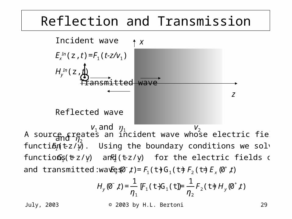
Reflection and TransmissionIncident wave
ExIn(z,t)=F1(t-z/v1)
HyIn(z,t) Transmitted wave
Reflected wave
v1 and 1 v2 and 2
x
z
€
A source creates an incident wave whose electric field is given by the known
function F1(t- z/v1). Using the boundary conditions we solve for the unknown
functions G1(t+z/v1) and F2(t- z/v2) for the electric fields of the reflected
and transmitted waves: Ex(0−,t)=F1(t)+G1(t)=F2(t)=Ex(0
+,t)
Hy(0−,t) =
1η1
F1(t)-G1(t)[ ]=1η2
F2(t)=Hy(0+,t)

July, 2003 © 2003 by H.L. Bertoni 30
Reflection and Transmission Coefficients
€
Solution of the boundary condition equations for G1(t) and F2(t) in terms of F1(t)
G1(t)=ΓF1(t) F2(t) =ΤF1(t)
The reflection coefficient Γ and transmission coefficient Τ are given by:
Γ =η2 −η1
η2 +η1
Τ =1+Γ =2η2
η2 +η1
Examples:
I. Suppose medium 1 is air so that η1 =η ≡ μo εo =377 and medium 2 has
relative dielectric constant εr =4 so that η2 = μo εrεo =0.5η. Then going
from air- to-dielectric Γad =0.5η −η0.5η +η
=−13
and Τad =1−13
=23
July, 2003 © 2003 by H.L. Bertoni 31
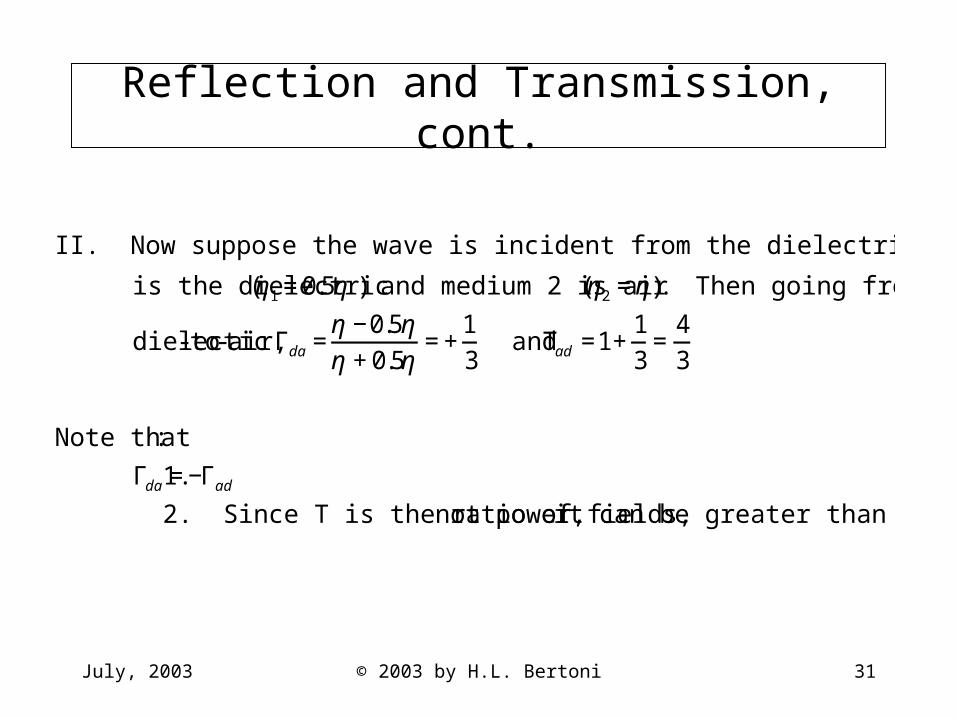
Reflection and Transmission, cont.
€
II. Now suppose the wave is incident from the dielectric onto air so that medium 1
is the dielectric η1 =0.5η ( ) and medium 2 is air η2 =η( ). Then going from
dielectic- to-air, Γda =η −0.5ηη +0.5η
=+13
and Τad =1+13
=43
Note that:
1. Γda =−Γad
2. Since T is the ratio of fields, not power, it can be greater than 1.
July, 2003 © 2003 by H.L. Bertoni 32
Reflected and Transmitted Power
€
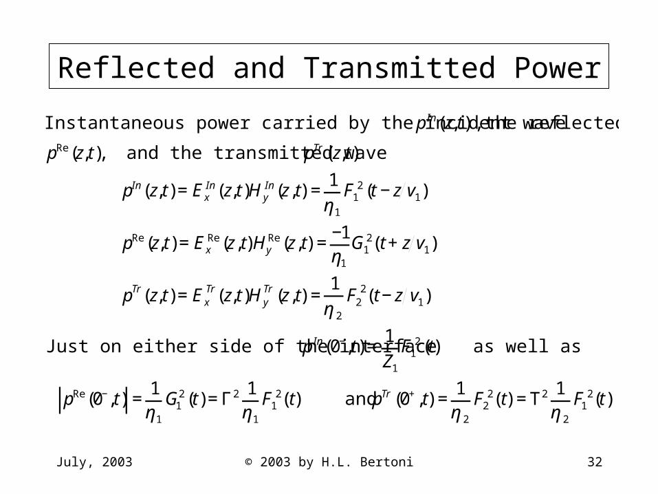
Instantaneous power carried by the incident wave pIn(z,t), the reflected wave
pRe(z,t), and the transmitted wave pTr(z,t)
pIn(z,t)=ExIn(z,t)Hy
In(z,t) =1η1
F12(t−z v1)
pRe(z,t)=ExRe(z,t)Hy
Re(z,t) =−1η1
G12(t+z v1)
pTr(z,t)=ExTr(z,t)Hy
Tr(z,t) =1
η2
F22(t−z v1)
Just on either side of the interface pIn(0−,t)=1Z1
F12(t) as well as
pRe(0−,t) =1η1
G12(t)=Γ2 1
η1
F12(t) and pTr(0+,t) =
1η2
F22(t) =Τ2 1
η2
F12(t)

July, 2003 © 2003 by H.L. Bertoni 33
Conservation of Power and Reciprocity
€
Conservation of power requires that pIn(0−,t)−pRe(0−,t) =pTr(0+,t) so that
1η1
F12(t)−Γ2 1
η1
F12(t)=Τ2 1
η2
F12(t) or 1−Γ2 =Τ2 η1
η2
This relation is easily shown to be satisfied from the expressions for Γ, Τ.
For waves going from medium 2 to medium 1, the reflection coefficient Γ12 is
the negative of Γ21 going from medium 1 to medium 2. Thus for either
case the ratios pRe(0−,t)
pIn(0−,t)=Γ2 and
pTr(0+,t)pIn(0−,t)
=1−Γ2 are the same.
Therefore the same fraction of the incident power is reflected from and
transmitted through the interface for waves incident from either medium.
This result is an example of a very general wave property called reciprocity.
July, 2003 © 2003 by H.L. Bertoni 34
Termination of a Transmission Line
I(0-,t)
TL V(0-,t) + RL
0 z
€
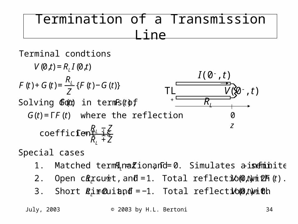
Terminal condtions
V(0,t) =RL I (0,t)
F(t)+G(t)=RL
ZF(t)−G(t){ }
Solving for G(t) in terms of F (t),
G(t) =ΓF(t) where the reflection
coefficient is Γ =RL −ZRL +Z
Special cases:
1. Matched termination, RL =Z and Γ =0. Simulates a semi- infinite TL
2. Open circuit, RL → ∞ and Γ =1. Total reflection with V(0,t) =2F (t).
3. Short circuit, RL =0 and Γ =−1. Total reflection with V(0,t)=0.
July, 2003 © 2003 by H.L. Bertoni 35
Reflections at Multiple Interfaces
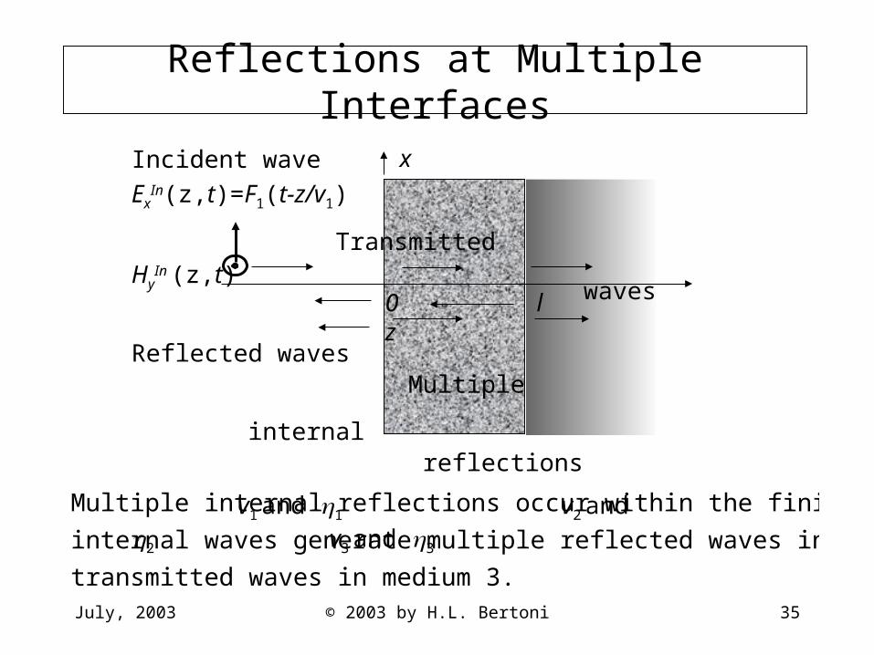
Incident wave
ExIn(z,t)=F1(t-z/v1)
TransmittedHy
In (z,t) waves
Reflected waves Multiple
internal reflections
v1 and 1 v2 and 2 v3 and 3
x
0 l z
€
Multiple internal reflections occur within the finite thickness layer. These
internal waves generate multiple reflected waves in medium 1 and multiple
transmitted waves in medium 3.
July, 2003 © 2003 by H.L. Bertoni 36
Scattering Diagram for a Layer
1
l z
2l/v2
4l/v2
t
€
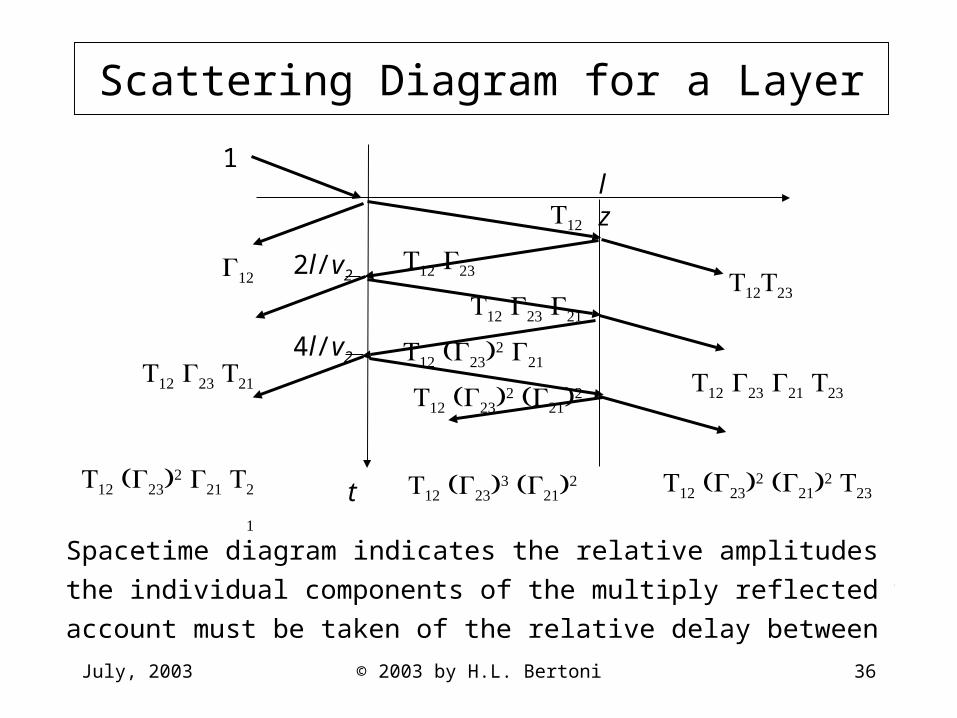
Space- time diagram indicates the relative amplitudes of the electric field of
the individual components of the multiply reflected waves. In adding fields,
account must be taken of the relative delay between the different components.
July, 2003 © 2003 by H.L. Bertoni 37
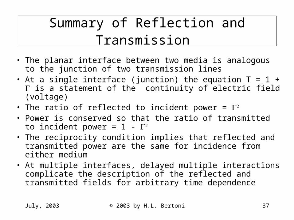
Summary of Reflection and Transmission
• The planar interface between two media is analogous to the junction of two transmission lines
• At a single interface (junction) the equation T = 1 + is a statement of the continuity of electric field (voltage)
• The ratio of reflected to incident power =
• Power is conserved so that the ratio of transmitted to incident power = 1 -
• The reciprocity condition implies that reflected and transmitted power are the same for incidence from either medium
• At multiple interfaces, delayed multiple interactions complicate the description of the reflected and transmitted fields for arbitrary time dependence

July, 2003 © 2003 by H.L. Bertoni 38
Spatial Variations for Harmonic Time Dependence
• Traveling and standing wave representations of the z dependence
• Period average power• Impedance transformations to account for layered
materials• Frequency dependence of reflection from a layer
July, 2003 © 2003 by H.L. Bertoni 39
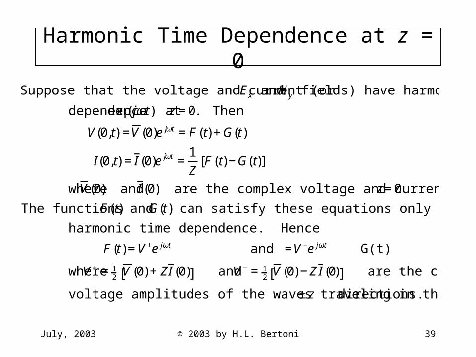
Harmonic Time Dependence at z = 0
€
Suppose that the voltage and current (or Ex and Hy fields) have harmonic time
dependence exp( jωt) at z=0. Then
V(0,t) =V(0)e jωt =F(t)+G(t)
I(0,t) =I (0)e jωt =1Z
F(t)−G(t)[ ]
where V(0) and I (0) are the complex voltage and current at z=0.
The functions F(t) and G(t) can satisfy these equations only if they too have
harmonic time dependence. Hence
F(t)=V+e jωt and G(t)=V−e jωt
where V+ =12 V(0)+ZI (0)[ ] and V−=1
2 V(0)−ZI (0)[ ] are the complex
voltage amplitudes of the waves traveling in the ±z directions.

July, 2003 © 2003 by H.L. Bertoni 40
Traveling Wave Representation
€
At other locations z≠0
V(z,t)=F(t−z v)+G(t+z v)=V+exp jω(t−z v)[ ]+V−exp jω(t+z v)[ ]
= V+e−jωz v +V−e+jωz v{ }e jωt =V(z)e jωt
I(z,t)=1Z
F(t−z v)−G(t+z v){ }=1Z
V+exp jω(t−z v)[ ]−V−exp jω(t+z v)[ ]{ }
=1Z
V+e−jωz v −V−e+jωz v{ }ejωt =I (z)ejωt
Here V(z) is the phasor voltage and I (z) is the phasor current, which give the
spatial variation for the implied time dependence exp( jωt).
Define the wave number (propagation constant) k ≡ω v m−1. Then
V(z)=V+e−jkz+V−e+jkz and I (z) =1Z
V +e−jkz−V−e+jkz{ }
is the traveling wave representation of phasor voltage and current.
July, 2003 © 2003 by H.L. Bertoni 41
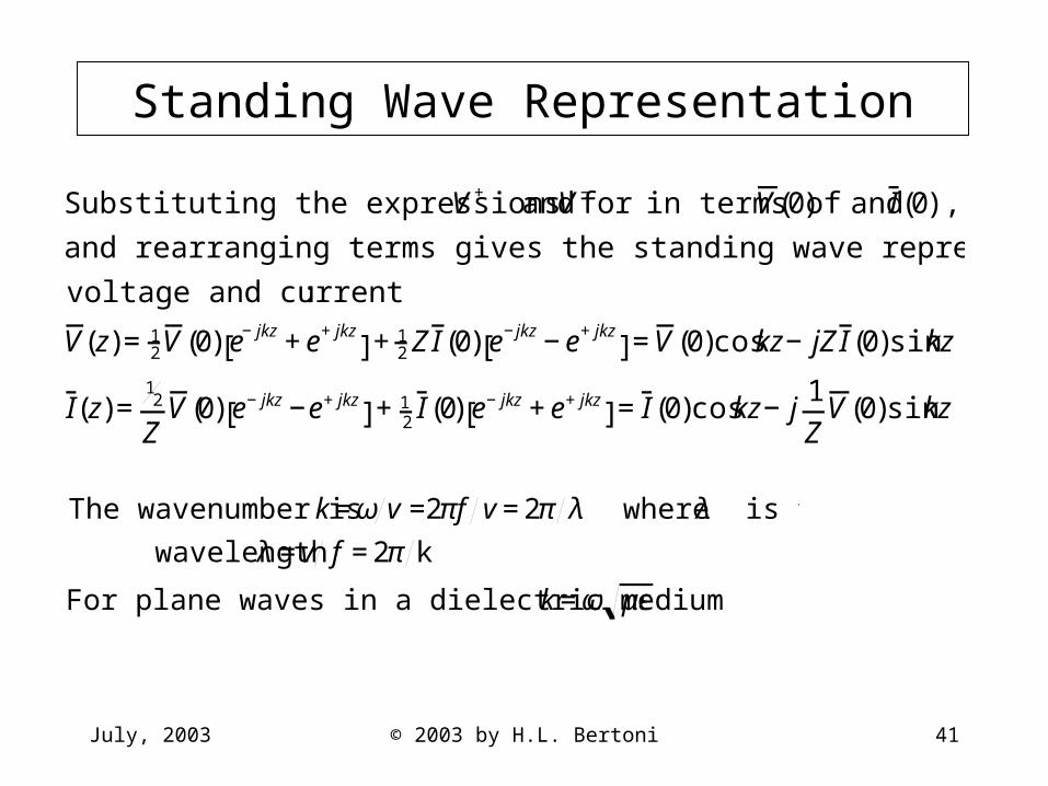
Standing Wave Representation
€
Substituting the expressions for V+ and V− in terms of V(0) and I (0),
and rearranging terms gives the standing wave representation of the phasor
voltage and current:
V(z)=12V(0) e−jkz+e+jkz
[ ]+12 ZI (0) e−jkz−e+jkz
[ ]=V(0)coskz−jZI (0)sinkz
I(z)=12
ZV(0) e−jkz−e+jkz
[ ]+12 I (0) e−jkz+e+jkz
[ ]=I (0)coskz−j1Z
V(0)sinkz
€
The wavenumber is k=ω v =2πf v=2π λ where λ is the
wavelength λ =v f =2π k
For plane waves in a dielectric medium k=ω με
July, 2003 © 2003 by H.L. Bertoni 42
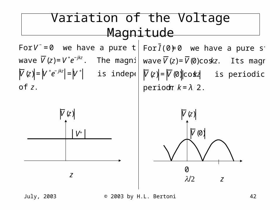
Variation of the Voltage Magnitude
|V+|
z
€
V(z)
€
For I (0)=0 we have a pure standing
wave V(z)=V(0)coskz. Its magnitude
V(z) =V(0) coskz is periodic with
period π k=λ 2.
0 z
€
V(z)
€
V(0)
July, 2003 © 2003 by H.L. Bertoni 43
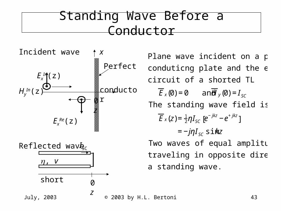
Standing Wave Before a Conductor
ISC
, v short
0 z
Incident wave
ExIn(z)
HyIn(z)
ExRe(z)
Reflected wave
x
Perfect
conductor
0 z
€
Plane wave incident on a perfectly
conduticng plate and the equivalent
circuit of a shorted TL
E x(0) =0 and H y(0) =I SC
The standing wave field is
E x(z)=12ηISC e−jkz−e+jkz
[ ]
=−jηI SC sinkz
Two waves of equal amplitude and
traveling in opposite directions create
a standing wave.

July, 2003 © 2003 by H.L. Bertoni 44
Standing Wave Before a Conductor, cont.
€
Plot of the magnitude of the standing wave field
E x(z) =ηISC sinkz
ISC
-z
July, 2003 © 2003 by H.L. Bertoni 45
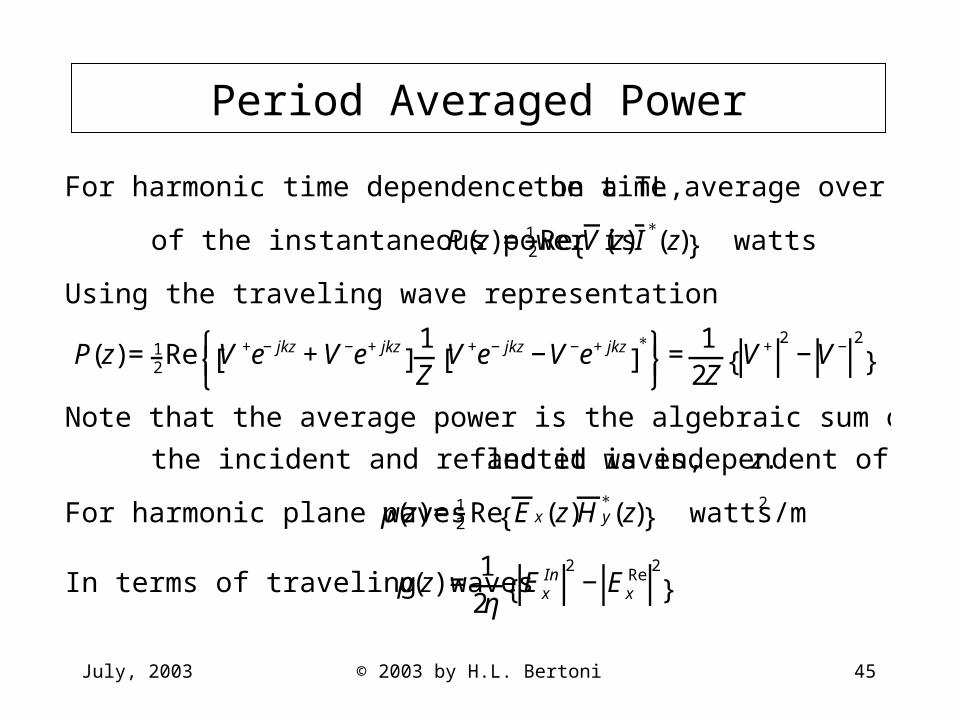
Period Averaged Power
€
For harmonic time dependence on a TL, the time average over one period
of the instantaneous power is P(z)=12Re V(z)I
∗(z){ } watts
Using the traveling wave representation
P(z)=12Re V +e−jkz+V−e+jkz
[ ]1Z
V+e−jkz−V−e+jkz[ ]
∗⎧ ⎨ ⎩
⎫ ⎬ ⎭
=1
2ZV+ 2
−V− 2
{ }
Note that the average power is the algebraic sum of the power carried by
the incident and reflected waves, and it is independent of z.
For harmonic plane waves p(z) =12 Re E x(z)H y
∗(z){ } watts/m2
In terms of traveling waves p(z) =12η
ExIn 2
−ExRe 2
{ }
July, 2003 © 2003 by H.L. Bertoni 46
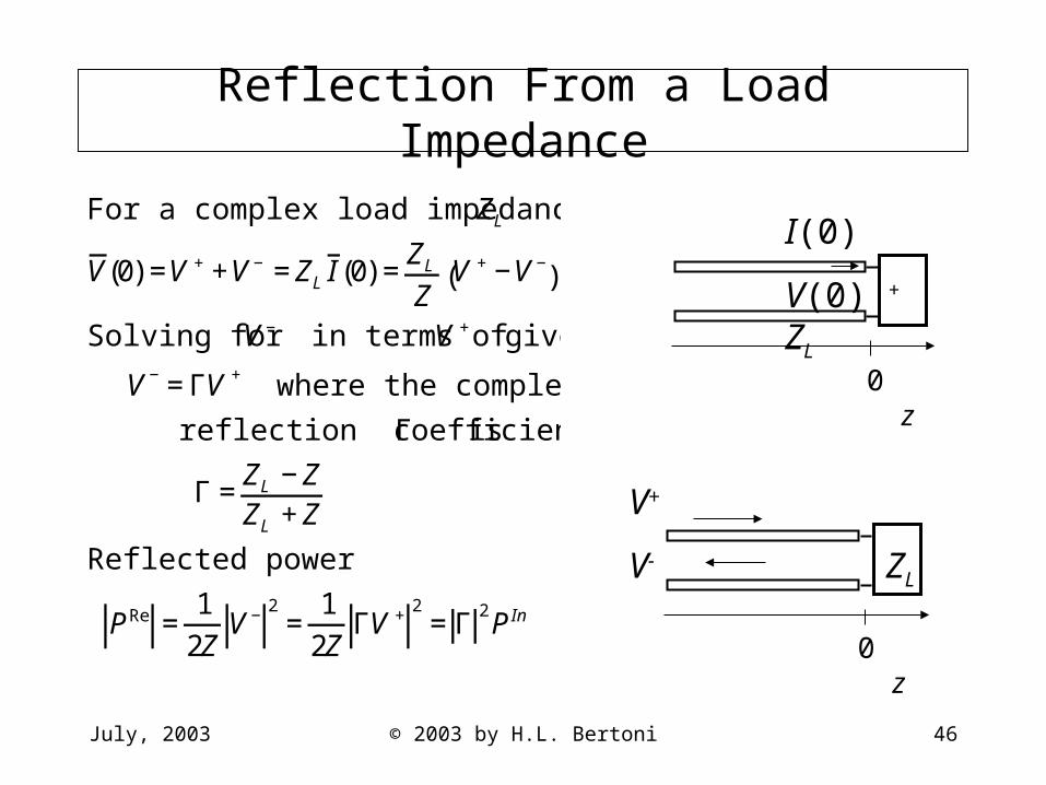
Reflection From a Load Impedance
V+
V- ZL
0 z
I(0)
V(0) + ZL
0 z
€
For a complex load impedance ZL
V(0) =V ++V− =ZL I (0) =ZL
ZV +−V−( )
Solving for V− in terms of V + gives
V−=ΓV + where the complex
reflection coefficient Γ is
Γ =ZL −ZZL +Z
Reflected power
PRe =1
2ZV− 2
=1
2ZΓV + 2
=Γ2P In
July, 2003 © 2003 by H.L. Bertoni 47
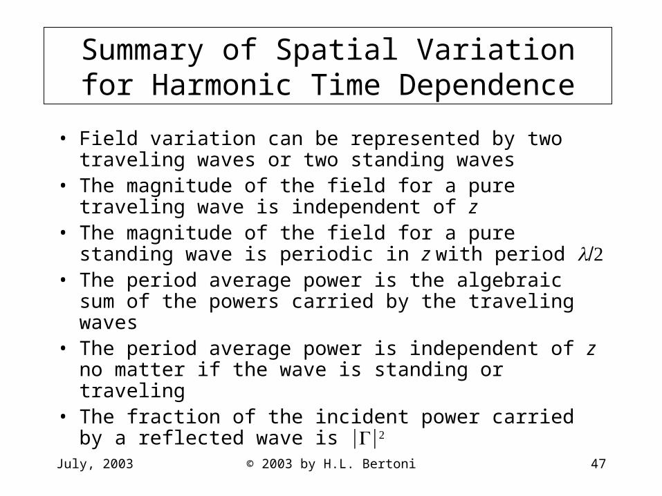
Summary of Spatial Variation for Harmonic Time Dependence
• Field variation can be represented by two traveling waves or two standing waves
• The magnitude of the field for a pure traveling wave is independent of z
• The magnitude of the field for a pure standing wave is periodic in z with period
• The period average power is the algebraic sum of the powers carried by the traveling waves
• The period average power is independent of z no matter if the wave is standing or traveling
• The fraction of the incident power carried by a reflected wave is
July, 2003 © 2003 by H.L. Bertoni 48
Impedance Transformations in Space
• Impedance variation in space• Using impedance for material layers• Frequency dependence of reflection from a brick
wall• Quarter wave matching layer
July, 2003 © 2003 by H.L. Bertoni 49
Defining Impedance Along a TL
I(0)
ZIN V(0) + ZL
-l 0 z
€
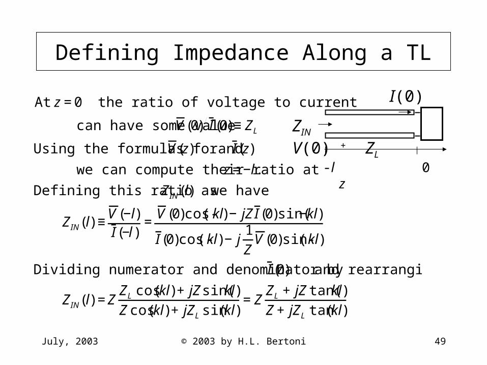
At z=0 the ratio of voltage to current
can have some value V(0) I (0)≡ZL
Using the formulas for V(z) and I (z)
we can compute their ratio at z=−l.
Defining this ratio as ZIN(l) we have
ZIN(l) ≡V(−l)I (−l)
=V(0)cos(-kl)−jZI (0)sin(−kl)
I (0)cos(-kl)−j1Z
V(0)sin(-kl)
Dividing numerator and denominator by I (0) and rearranging gives
ZIN(l) =ZZL cos(kl)+jZsin(kl)Zcos(kl)+jZL sin(kl)
=ZZL +jZtan(kl)Z+jZL tan(kl)
July, 2003 © 2003 by H.L. Bertoni 50
Properties of the Impedance Transform
€
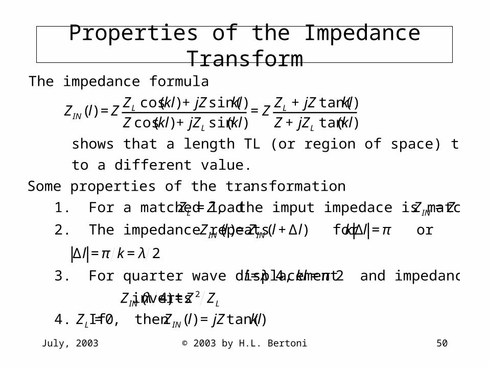
The impedance formula
ZIN(l) =ZZL cos(kl)+jZsin(kl)Zcos(kl)+jZL sin(kl)
=ZZL +jZtan(kl)Z+jZL tan(kl)
shows that a length TL (or region of space) transforms an impedance
to a different value.
Some properties of the transformation:
1. For a matched load ZL =Z, the imput impedace is matched ZIN =Z
2. The impedance repeats ZIN (l)=ZIN(l+Δl) for kΔl =π or
Δl =π k=λ 2
3. For quarter wave displacement l=λ 4, kl=π 2 and impedance
inverts ZIN (λ 4) =Z2 ZL
4. If ZL =0, then ZIN(l) =jZtan(kl)
July, 2003 © 2003 by H.L. Bertoni 51
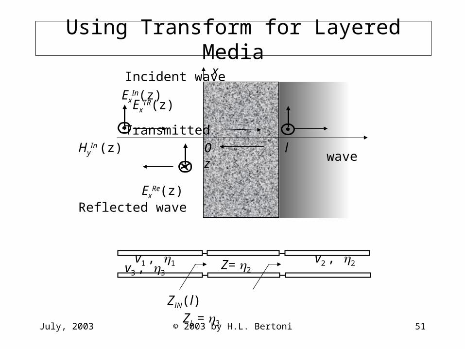
Using Transform for Layered Media
Incident wave
ExIn(z) Ex
TR(z) Transmitted
HyIn (z) wave
ExRe(z)
Reflected wave
v1 , 1 v2 , 2 v3 , 3
x
0 l z
ZIN(l) ZL = 3
Z= 2
July, 2003 © 2003 by H.L. Bertoni 52
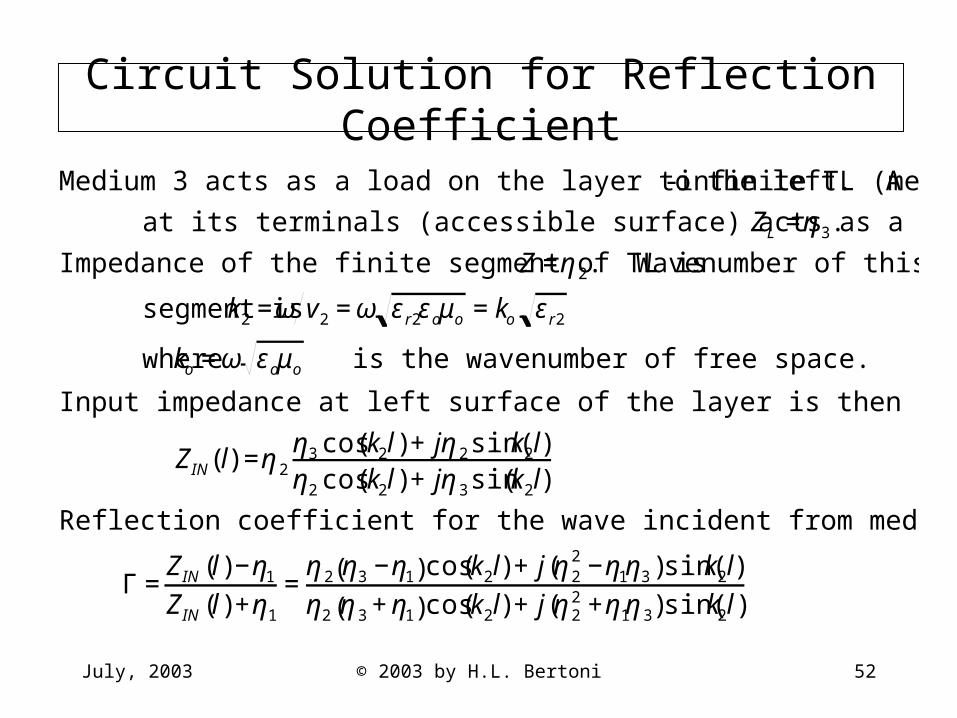
Circuit Solution for Reflection Coefficient
€
Medium 3 acts as a load on the layer to the left. A semi- infinite TL (medium)
at its terminals (accessible surface) acts as a resistor so that ZL =η3.
Impedance of the finite segment of TL is Z=η2. Wavenumber of this
segment is k2 =ω v2 =ω εr2εoμo =ko εr2
where ko =ω εoμo is the wavenumber of free space.
Input impedance at left surface of the layer is then
ZIN(l) =η2η3 cos(k2l)+jη2sin(k2l)η2 cos(k2l)+jη3sin(k2l)
Reflection coefficient for the wave incident from medium 1 is
Γ =ZIN (l)−η1
ZIN (l)+η1
=η2 η3 −η1( )cos(k2l)+j(η2
2 −η1η3)sin(k2l)η2 η3 +η1( )cos(k2l)+j(η2
2 +η1η3)sin(k2l)
July, 2003 © 2003 by H.L. Bertoni 53
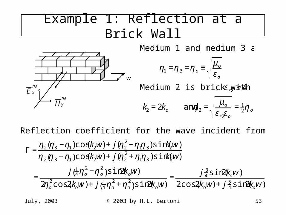
Example 1: Reflection at a Brick Wall
€
HyIN
€
E xIN
w
€
Medium 1 and medium 3 are air
η1 =η3 =ηo ≡μo
εo
Medium 2 is brick with εr2 ≈4
k2 =2ko and η2 =μo
εr2εo
=12ηo
€
Reflection coefficient for the wave incident from air is
Γ =η2 η3 −η1( )cos(k2w)+j(η2
2 −η1η3)sin(k2w)η2 η3 +η1( )cos(k2w)+j(η2
2 +η1η3)sin(k2w)
=j 1
4 ηo2 −ηo
2( )sin(2kow)
2ηo2cos(2kow)+j 1
4 ηo2 +ηo
2( )sin(2kow)
=j 3
4 sin(2kow)2cos(2kow)+j 5
4 sin(2kow)
July, 2003 © 2003 by H.L. Bertoni 54
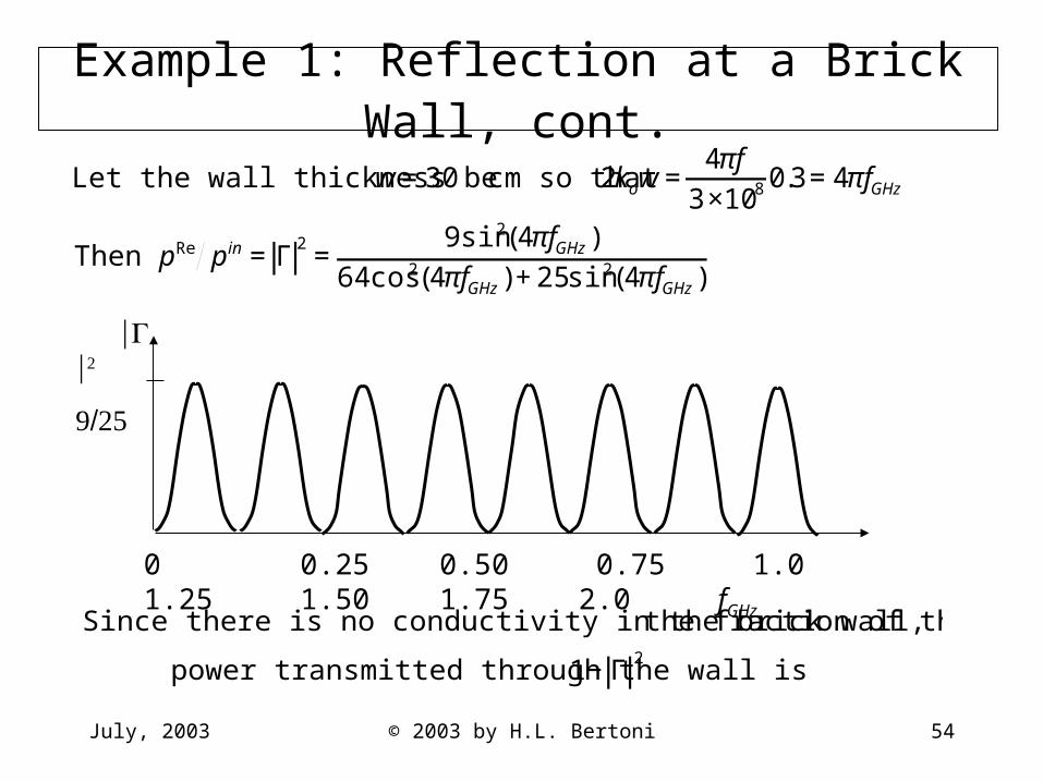
Example 1: Reflection at a Brick Wall, cont.
€
Let the wall thickness be w=30 cm so that 2kow=4πf
3×10⁸ 0.3=4πfGHz
Then pRe pin =Γ2=
9sin2(4πfGHz)64cos2(4πfGHz)+25sin2(4πfGHz)
€
Since there is no conductivity in the brick wall, the fraction of the incident
power transmitted through the wall is 1−Γ2
0 0.25 0.50 0.75 1.0 1.25 1.50 1.75 2.0 fGHz
July, 2003 © 2003 by H.L. Bertoni 55
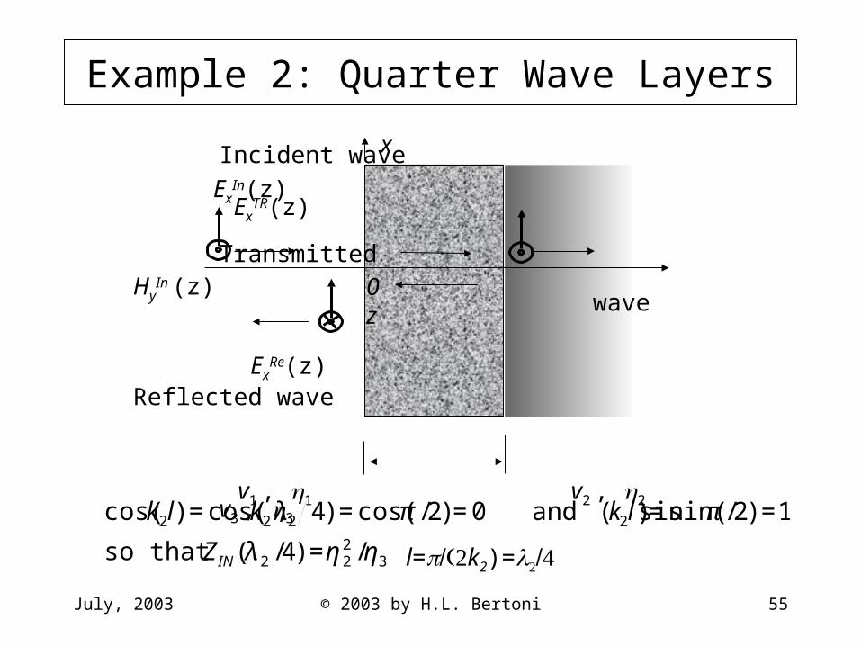
Example 2: Quarter Wave Layers
Incident wave
ExIn(z) Ex
TR(z) Transmitted
HyIn (z) wave
ExRe(z)
Reflected wave
v1 , 1 v2 , 2 v3 , 3 l=k2)=
x
0 z
€
cos(k2l) =cos(k2 λ2 4) =cos(π /2)=0 and sin(k2l)=sin(π /2) =1
so that ZIN(λ2 /4) =η22 /η3
July, 2003 © 2003 by H.L. Bertoni 56
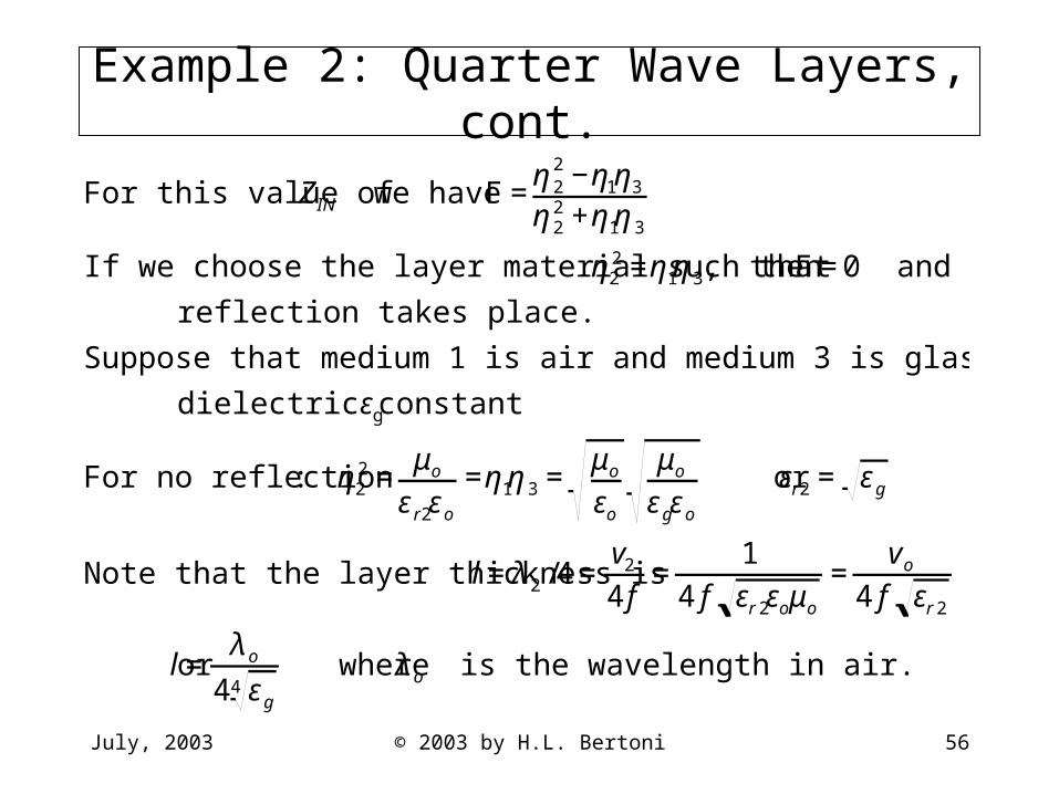
Example 2: Quarter Wave Layers, cont.
€
For this value of ZIN we have Γ =η2
2 −η1η3
η22 +η1η3
If we choose the layer material such that η22 =η1η3, then Γ =0 and no
reflection takes place.
Suppose that medium 1 is air and medium 3 is glass with relative
dielectric constant εg
For no reflection: η22 =
μo
εr2εo
=η1η3 =μo
εo
μo
εgεo
or εr2 = εg
Note that the layer thickness is l =λ2 /4=v2
4f=
14 f εr 2εoμo
=vo
4 f εr 2
or l =λo
4 εg4
where λo is the wavelength in air.
July, 2003 © 2003 by H.L. Bertoni 57
Summary of Impedance Transformation
• The impedance repeats every half wavelength in space, and is inverted every quarter wavelength
• Impedances can be cascaded to find the impedance seen by an incident wave
• Reflection from a layer has periodic frequency dependence with minima (or maxima) separated by f = v2/(2w)
• Quarter wave layers can be used impedance matching to eliminate reflections
July, 2003 © 2003 by H.L. Bertoni 58
Effect of Material Conductivity
• Equivalent circuit for accounting for conductivity• Conductivity of some common dielectrics• Effect of conductivity on wave propagation
July, 2003 © 2003 by H.L. Bertoni 59
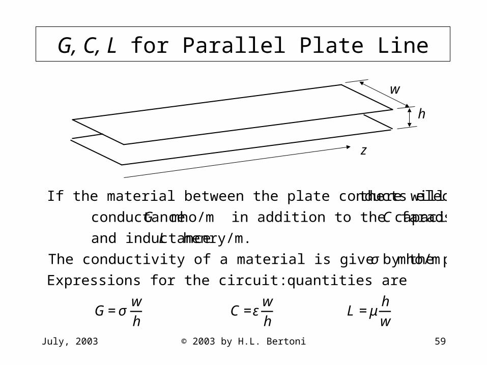
G, C, L for Parallel Plate Line
w
h
z
€
If the material between the plate conducts electricity, there will be a
conductance G mho/m in addition to the capacitance C farads/m
and inductance L henry/m.
The conductivity of a material is give by the parameter σ mho/m
Expressions for the circuit quantities are:
G=σwh
C =εwh
L =μhw
July, 2003 © 2003 by H.L. Bertoni 60
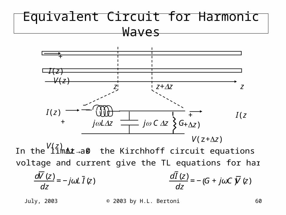
Equivalent Circuit for Harmonic Waves
€
In the limit as Δz→ 0 the Kirchhoff circuit equations for the phasor
voltage and current give the TL equations for harmonic time dependence
dV(z)
dz=−jωLI (z)
dI (z)dz
=−G+jωC( )V(z)
+
I(z) V(z)
-z z+z z
I(z) +
V(z)
+ I(z +z)
V(z+z) jLz j C z G

July, 2003 © 2003 by H.L. Bertoni 61
Harmonic Fields and Maxwell’s Equations
€
If w>>h, the fields between the plates are nearly constant over the cross-section,
so that the phasor circuit quantities are V(z)=−hE x(z) and I (z) =−wHy(z).
Substituting these exprsssions in the TL equations for harmonic time dependence,
along with the expressions for G, C, L gives Maxwell's equations
dE x(z)
dz=−jωμHy(z)
dH y(z)dz
=− jωε+σ( )E x(z)
w
h
z
y Hy(z)
I(z)x +
V(z)
Ex(z)
July, 2003 © 2003 by H.L. Bertoni 62
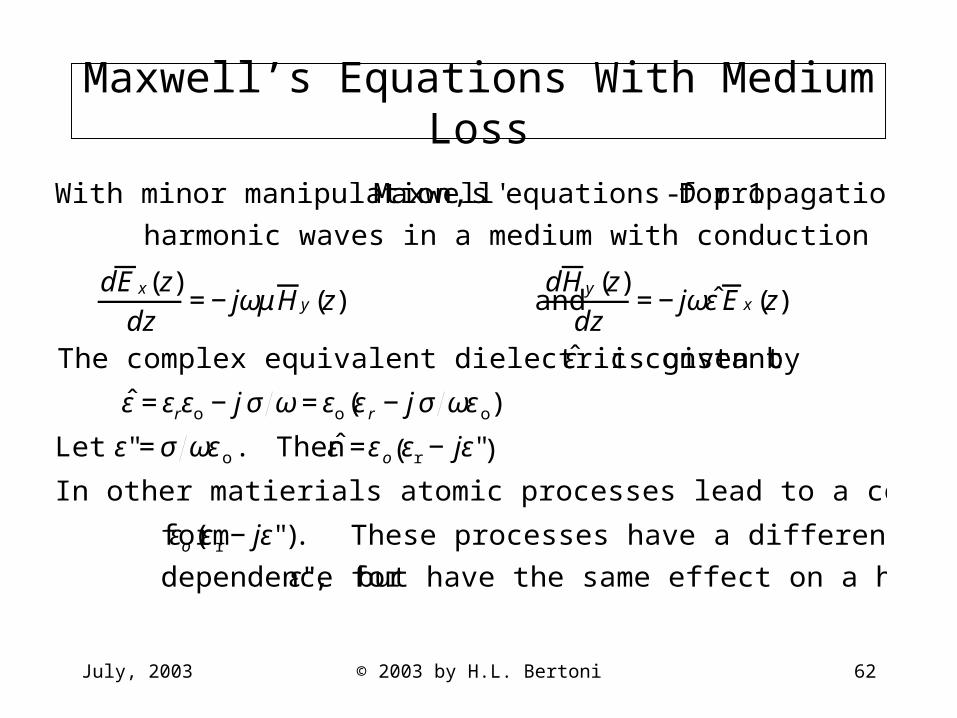
Maxwell’s Equations With Medium Loss
€
With minor manipulation, Maxwell's equations for 1-D propagation of
harmonic waves in a medium with conduction loss can be written
dE x(z)
dz=−jωμHy(z) and
dHy(z)dz
=−jωˆ ε E x(z)
The complex equivalent dielectric constant ˆ ε is given by
ε =εrεo −j σ ω=εo εr −j σ ωεo( )
Let ε"=σ ωεo. Then ε =εo εr −jε"( )
In other matierials atomic processes lead to a complex dielectric of the
form εo εr −jε"( ). These processes have a different frequency
dependence for ε", but have the same effect on a hamonic wave
July, 2003 © 2003 by H.L. Bertoni 63
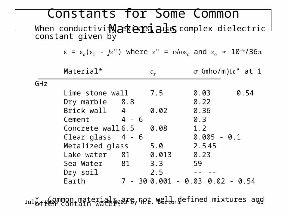
Constants for Some Common MaterialsWhen conductivity exists, use complex dielectric constant given by
= o(r - j") where " = o and o 10-9/36
Material* r mho/m)" at 1 GHz
Lime stone wall 7.5 0.03 0.54Dry marble 8.8 0.22Brick wall 4 0.02 0.36Cement 4 - 6 0.3Concrete wall 6.5 0.08 1.2Clear glass 4 - 6 0.005 - 0.1Metalized glass 5.0 2.5 45Lake water 81 0.013 0.23Sea Water 81 3.3 59Dry soil 2.5 -- --Earth 7 - 30 0.001 - 0.03 0.02 - 0.54
* Common materials are not well defined mixtures and often contain water.
July, 2003 © 2003 by H.L. Bertoni 64
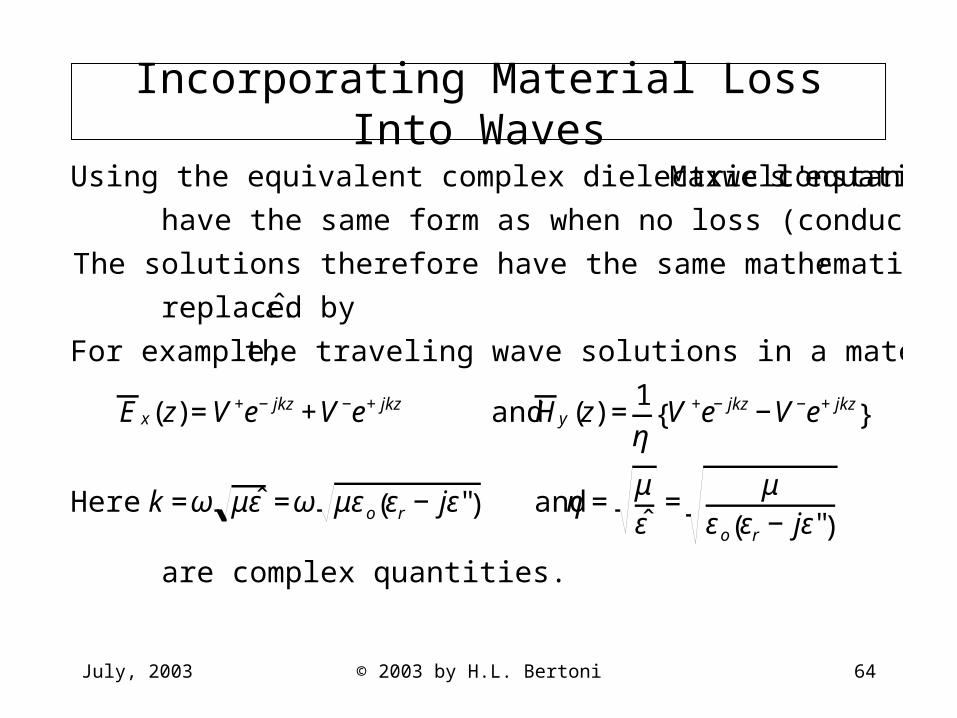
Incorporating Material Loss Into Waves
€
Using the equivalent complex dielectric constant, Maxwell's equations
have the same form as when no loss (conductivity) is present.
The solutions therefore have the same mathematical form with ε
replaced by ˆ ε .
For example, the traveling wave solutions in a material are
E x(z)=V+e−jkz+V−e+jkz and Hy(z) =1η
V +e−jkz−V−e+jkz{ }
Here k =ω μˆ ε =ω μεo εr −jε"( ) and η =μˆ ε
=μ
εo εr −jε"( )
are complex quantities.
July, 2003 © 2003 by H.L. Bertoni 65
Wave Number and Impedance
€
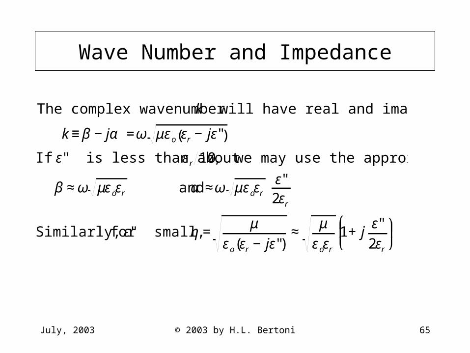
The complex wavenumber k will have real and imaginary parts
k≡β −jα =ω μεo εr −jε"( )
If ε" is less than about εr 10, we may use the approximations
β ≈ω μεoεr and α ≈ω μεoεr ε"2εr
Similarly, for ε" small, η =μ
εo εr −jε"( )≈
μεoεr
1+jε"2εr
⎛
⎝ ⎜ ⎞
⎠ ⎟
July, 2003 © 2003 by H.L. Bertoni 66
Effect of Loss on Traveling Waves
€
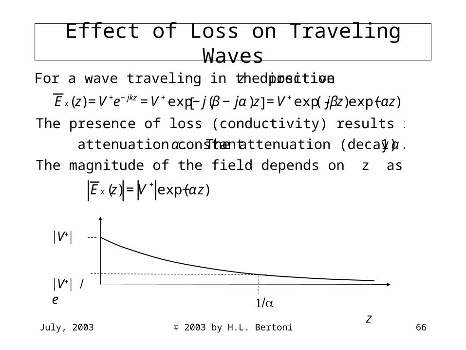
For a wave traveling in the positive z direction
E x(z)=V+e−jkz=V+exp−j(β−jα)z[ ]=V+exp(- jβz)exp(−αz)
The presence of loss (conductivity) results in a finite value of the
attenuation constant α. The attenuation (decay) length is 1α.
The magnitude of the field depends on z as given by
E x(z) =V +exp(−αz)
V+
V+e
z
July, 2003 © 2003 by H.L. Bertoni 67
Attenuation in dB
€
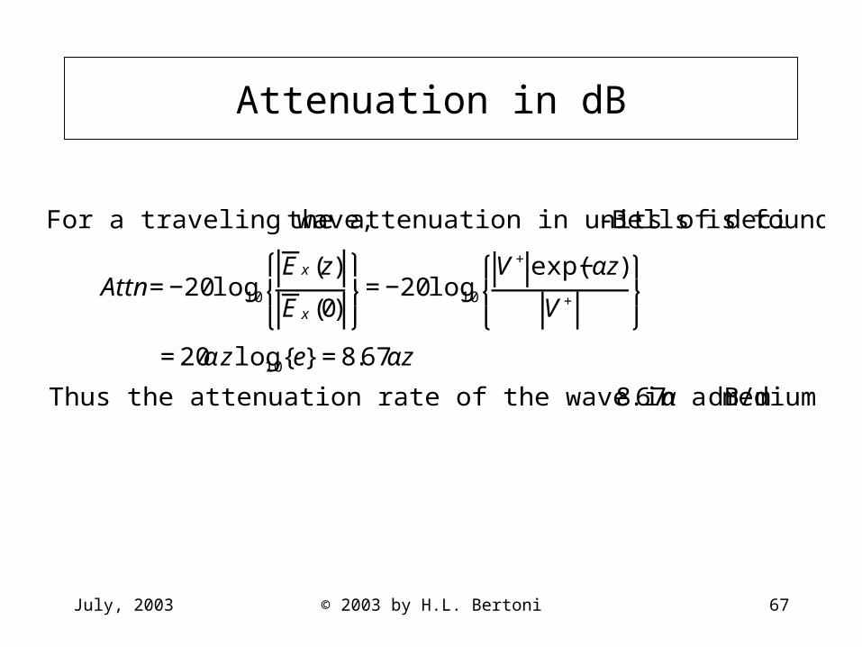
For a traveling wave, the attenuation in units of deci-Bells is found from
Attn=−20log10
E x(z)
E x(0)
⎧ ⎨ ⎩
⎫ ⎬ ⎭
=−20log10
V+exp(−αz)
V+
⎧ ⎨ ⎩
⎫ ⎬ ⎭
=20αzlog10 e{ }=8.67αz
Thus the attenuation rate of the wave in a medium is 8.67α dB/m
July, 2003 © 2003 by H.L. Bertoni 68
Effect of Loss on Traveling Waves, cont.
€
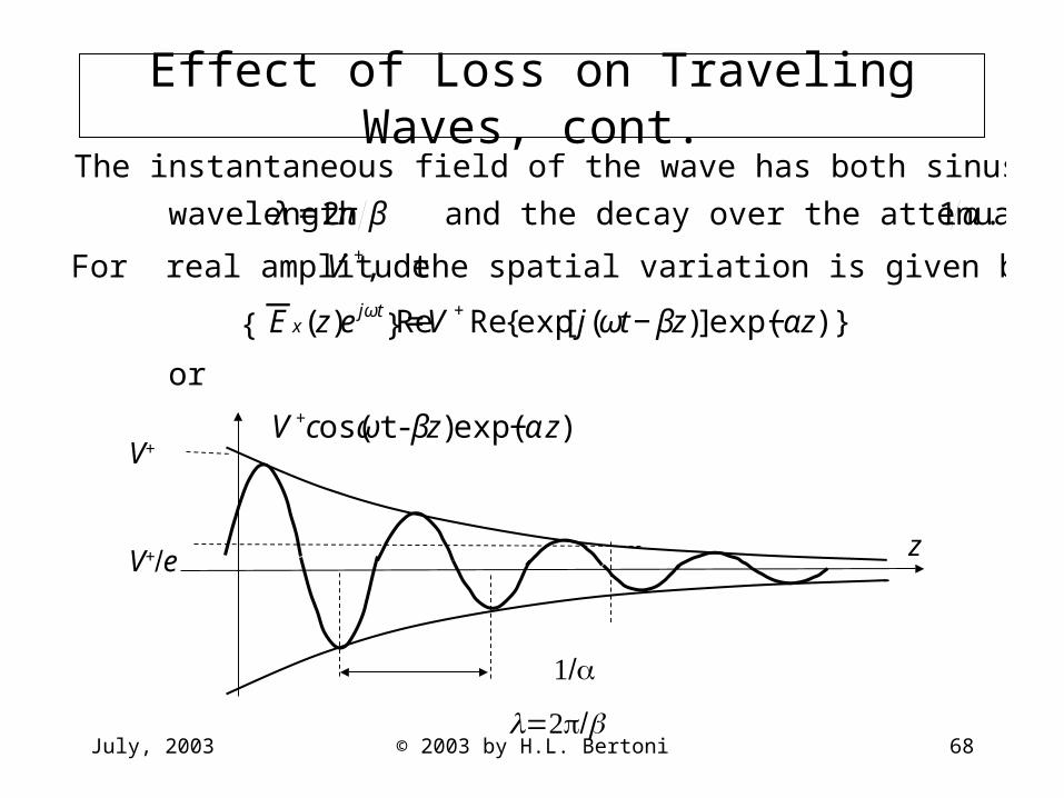
The instantaneous field of the wave has both sinusoidal variation over a
wavelength λ =2π β and the decay over the attenuation length 1α.
For real amplitude V +, the spatial variation is given by
Re E x(z)ejωt{ }=V +Re exp j(ωt−βz)[ ]exp(−αz) { }
or
V+cos(ωt-βz)exp(−αz)
V+
V+e z
July, 2003 © 2003 by H.L. Bertoni 69
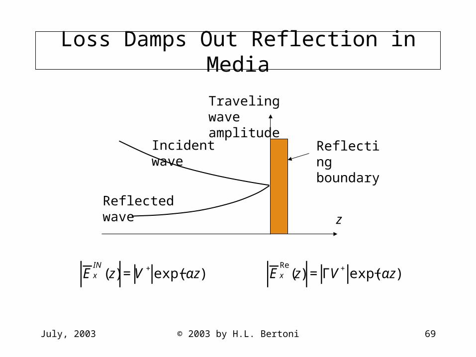
Loss Damps Out Reflection in Media
Traveling wave amplitude
z
Reflecting boundary
Incident wave
Reflected wave
€
E xIN
(z) =V +exp(−αz) E xRe
(z) =ΓV+ exp(+αz)

July, 2003 © 2003 by H.L. Bertoni 70
Effect of Damping on the || for a Wall
0 0.25 0.50 0.75 1.0 1.25 1.50 1.75 2.0 fGHz
€
With absorption in the brick wall, the interference minima are
reduced and the reflection coefficient approaches that of the
first air-brick interface or Γ =ηB −ηo
ηB +ηo
=−13
The fraction of the incident power transmitted through the
wall is ≠ 1−Γ2
July, 2003 © 2003 by H.L. Bertoni 71
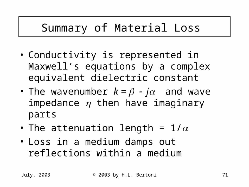
Summary of Material Loss
• Conductivity is represented in Maxwell’s equations by a complex equivalent dielectric constant
• The wavenumber k = j and wave impedance then have imaginary parts
• The attenuation length = 1/ • Loss in a medium damps out reflections within a
medium