Embed Size (px)
Citation preview
Presenter’s FormOne Day International Symposium on
“Current Research in Hydraulic Turbines, CRHT-III”7 April, 2014, KU, Dhulikhel, Nepal
Details of PresenterInstitution DesignationName of PresenterEmail PhoneResearch start date Research completing dateName of other related personnel (if applicable)Title of Presentation
Title of Research (if different from presentation)Summary of Research and Presentation (Use additional sheet if required)
Presenter’s Signature Date
Please submit this application no later than 1 March 2014 to:Turbine Testing Lab, Department of Mechanical Engineering, Kathmandu
UniversityGPO Box 6250, Dhulikhel, Nepal
Email: [email protected]
Korea Maritime & Ocean University
ACHARYA Nirmal
Graduate Student
[email protected] +82-10-2930-5487
LEE Young- Ho, KIM Byung- HaJune 2014June 2013
Numerical & Experimental Analysis of a Cross- flow Turbine with its Performance Enhancement by CFD code
Small scale hydro-power plants give the best solution to the power needs of rural and small communities whichserve as decentralized power source to meet the local population requirement. Cross- flow turbines are usedwidely in such hydro-power plants due to their simple design, easier maintenance, low initial investment andmodest efficiency. The main objective of this study is to compare the CFD simulation results with experimentaldata and to optimize its performance by geometrically modifying the parameters of the turbine. During theprocess, numerical analysis and experiments were conducted simultaneously on the base model available inthe laboratory and the results were compared. Afterwards the design was modified as by varying the shape ofnozzle, number of runner blades and shape of casing respectively and simulation was carried out individually.
Experiments were conducted in a dedicated test set-up. Pump provides the required head and the flow throughthe turbine. Electro-magnetic flow meter and pressure transducer at the upstream side are used for the flowrate and pressure measurement respectively. The turbine was coupled to powder brake through torque meterand the required parameters were recorded in the data logger. Experiment was conducted at various rpm. Fornumerical simulation, two phase (air & water at 25°C) steady state with SST turbulence model was selected inthe commercial CFD code ANSYS CFX 13.0. The design parameters include 10 m head, 0.1 m3/s flow rateand 642 rotational speed. At the design speed for full opening, experimental data show the efficiency of 61.68%whereas the numerical result show 63.73%. The best efficiency was obtained at 500 rpm from both experiment(64.14%) and simulation (64.81%) which find good agreement with each other. For the numerical results, thebest efficiency obtained from the base nozzle design with 74% guide vane opening was 65.87% which wasgeometrically modified that improved the turbine performance and the efficiency reached 80.76% (increase by14.89%). Velocity distribution, pressure contours, output torque within the flow domain were also characterized.
Performance Analysis & Design Optimization of a Cross- flow Hydro Turbine
Nirmal Acharya 28/02/2014
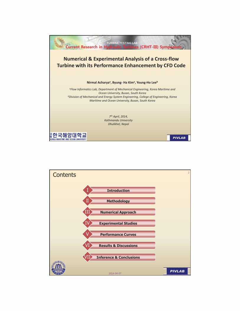
Numerical & Experimental Analysis of a Cross-flow Turbine with its Performance Enhancement by CFD Code
Nirmal Acharyaa, Byung- Ha Kima, Young-Ho Leeb
aFlow Informatics Lab, Department of Mechanical Engineering, Korea Maritime and Ocean University, Busan, South Korea
bDivision of Mechanical and Energy System Engineering, College of Engineering, Korea Maritime and Ocean University, Busan, South Korea
7th April, 2014, Kathmandu University
Dhulikhel, Nepal
Contents
IntroductionI
Numerical ApproachIII
Results & DiscussionsVI
Inference & ConclusionsVII
Methodology
Experimental StudiesIV
Performance CurvesV

Introduction (MHP)
• Micro hydro Power plants (5 kW -100 kW ) - solution to the power needs of small communities.• Small hydraulic sites present a variety of economic advantages.• Provide power for industrial, agricultural and domestic uses.• Cost effective source for the rural communities not fed by the national grid.
Cross- flow (Banki) Turbine
• Mainly consists of 2 parts; nozzle and turbine runner.• Water jet passes twice through the rotor blades.
• Applied over a wide head range (less than 2 m - more than 100 m).• Relatively flat efficiency curve.• Gained wide acceptance- due to simple construction, low cost of initial investment, easier maintenance and modest efficiency.
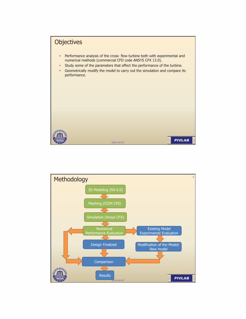
Objectives
• Performance analysis of the cross- flow turbine both with experimental and numerical methods (commercial CFD code ANSYS CFX 13.0).
• Study some of the parameters that effect the performance of the turbine.• Geometrically modify the model to carry out the simulation and compare its
performance.
Methodology
3D Modeling (NX 6.0)
Meshing (ICEM CFD
Simulation (Ansys CFX)
Numerical Performance Evaluation
Design Finalized
Comparison
Results
Existing Model Experimental Evaluation
Modification of the Model/ New model
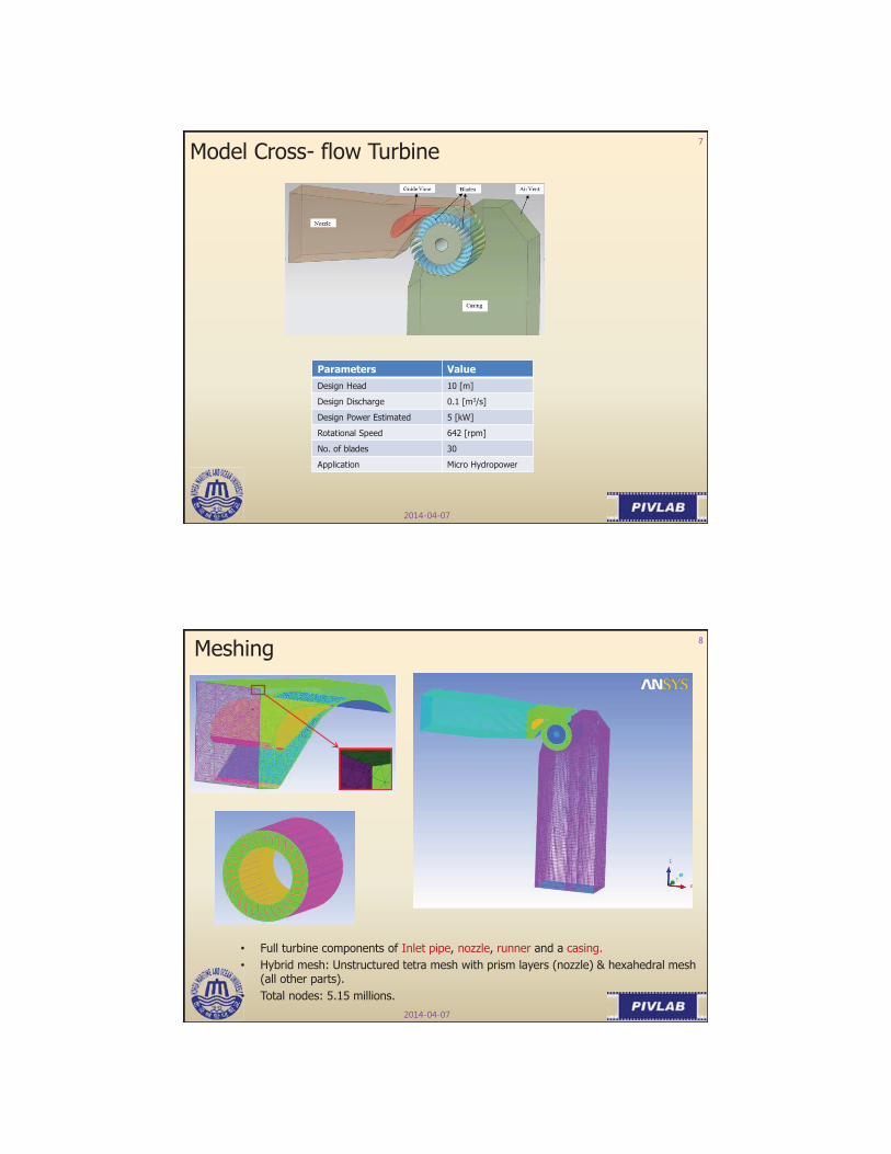
Model Cross- flow Turbine
Parameters ValueDesign Head 10 [m]
Design Discharge 0.1 [m3/s]
Design Power Estimated 5 [kW]
Rotational Speed 642 [rpm]
No. of blades 30
Application Micro Hydropower
Meshing
• Full turbine components of Inlet pipe, nozzle, runner and a casing.• Hybrid mesh: Unstructured tetra mesh with prism layers (nozzle) & hexahedral mesh
(all other parts).• Total nodes: 5.15 millions.

Numerical Approach
Numerical Code ANSYS CFX v. 13.0
Turbulence Model SST
Simulation Type Steady State
Physical Timescale 0.01487(1/ω)
Phase 2 phase (Air & Water @ 25 C)
Domain Nozzle, Rotor, Internal Fluid, Casing
Inlet 10 m pressure head @ pipe inlet
Outlet 0.1 m3/s flow rate @ casing outlet
Rotational Speed 642 rpm
•Standard homogeneous free surface model.•1st order turbulence numerics with high resolution advection scheme.•Nozzle/Runner/ Casing Interfaces: Frozen rotor type.
Qualitative Analysis (Velocity Vectors)Calculated results showed that the turbine has maximum ηof 63.60% with shaft power of 4.74 kW.
• Velocity gets accelerated just before the runner blade inlet.• From Stage I, cross- flow within the runner gains accelerated velocity once more and flow enters the inlet of Stage II.• Large recirculation flow is observed in the central region of the runner.

Qualitative Analysis (Pressure Contours)
•Turbine inlet pressure decreases along the nozzle passage but the pressure at the nozzle outlet is almost uniform.• The fluid pressure passing through the passage of the runner blades at Stage I drops rapidly.•Relatively low pressure is located in the central area of the runner, esp. in the area of region I.• From this result, it is assumed that the fluid pressure passing through the passage of runner is taken by runner blades; which then changes to O/P power.
Internal Flow Field of the Turbine
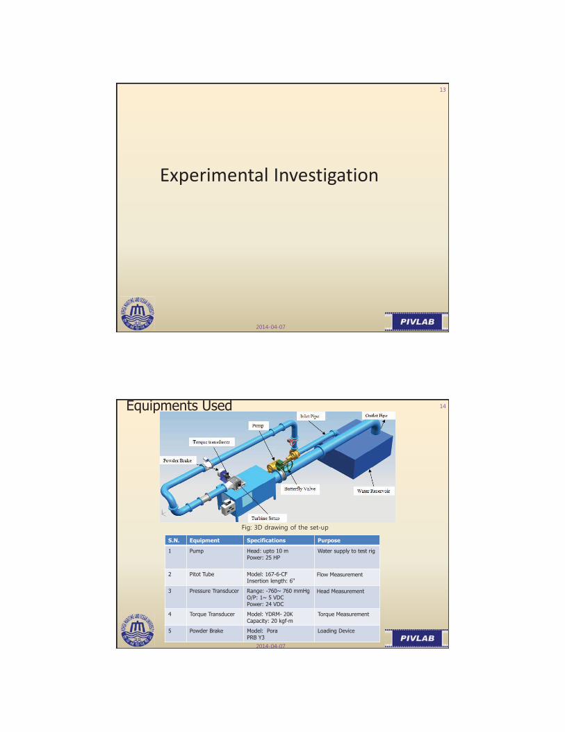
Experimental Investigation
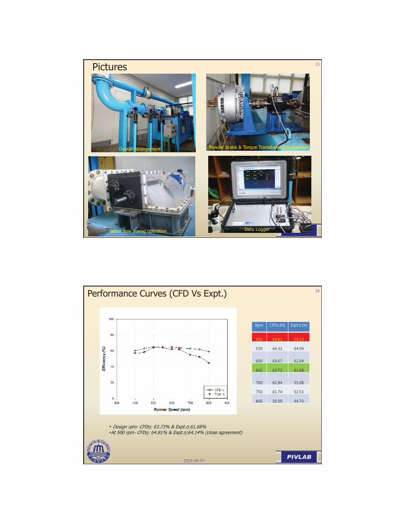
Equipments Used
S.N. Equipment Specifications Purpose
1 Pump Head: upto 10 mPower: 25 HP
Water supply to test rig
2 Pitot Tube Model: 167-6-CFInsertion length: 6"
Flow Measurement
3 Pressure Transducer Range: -760~ 760 mmHgO/P: 1~ 5 VDCPower: 24 VDC
Head Measurement
4 Torque Transducer Model: YDRM- 20KCapacity: 20 kgf-m
Torque Measurement
5 Powder Brake Model: PoraPRB Y3
Loading Device
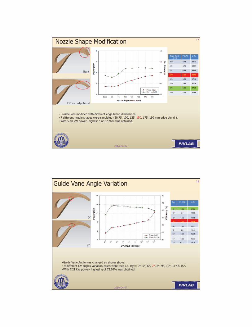
Overall Arrangement Powder Brake & Torque Transducer Arrangement
Water flow during operation Data Logger
Pictures
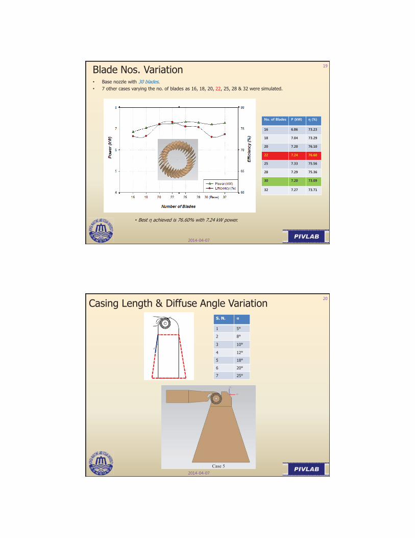
Performance Curves (CFD Vs Expt.)
• Design rpm- CFDη: 63.73% & Expt.η:61.68%•At 500 rpm- CFDη: 64.81% & Expt.η:64.14% (close agreement)
η (%) η (%)
Nozzle Shape Modification
• Nozzle was modified with different edge blend dimensions.• 7 different nozzle shapes were simulated (50,75, 100, 125, 150, 175, 190 mm edge blend ). • With 5.48 kW power- highest η of 67.26% was obtained.
Base
150 mm edge blend
Guide Vane Angle Variation
•Guide Vane Angle was changed as shown above.• 9 different GV angles variation cases were tried i.e. θgv= 0°, 5°, 6°, 7°, 8°, 9°, 10°, 11° & 15°.•With 7.21 kW power- highest η of 73.09% was obtained.
0°
7°
°
°
°
°
°
°
°
°
°
Blade Nos. Variation• Base nozzle with 30 blades.• 7 other cases varying the no. of blades as 16, 18, 20, 22, 25, 28 & 32 were simulated.
• Best η achieved is 76.60% with 7.24 kW power.
Casing Length & Diffuse Angle VariationS. N. α
1 5°
2 8°
3 10°
4 12°
5 18°
6 20°
7 25°
Case 5
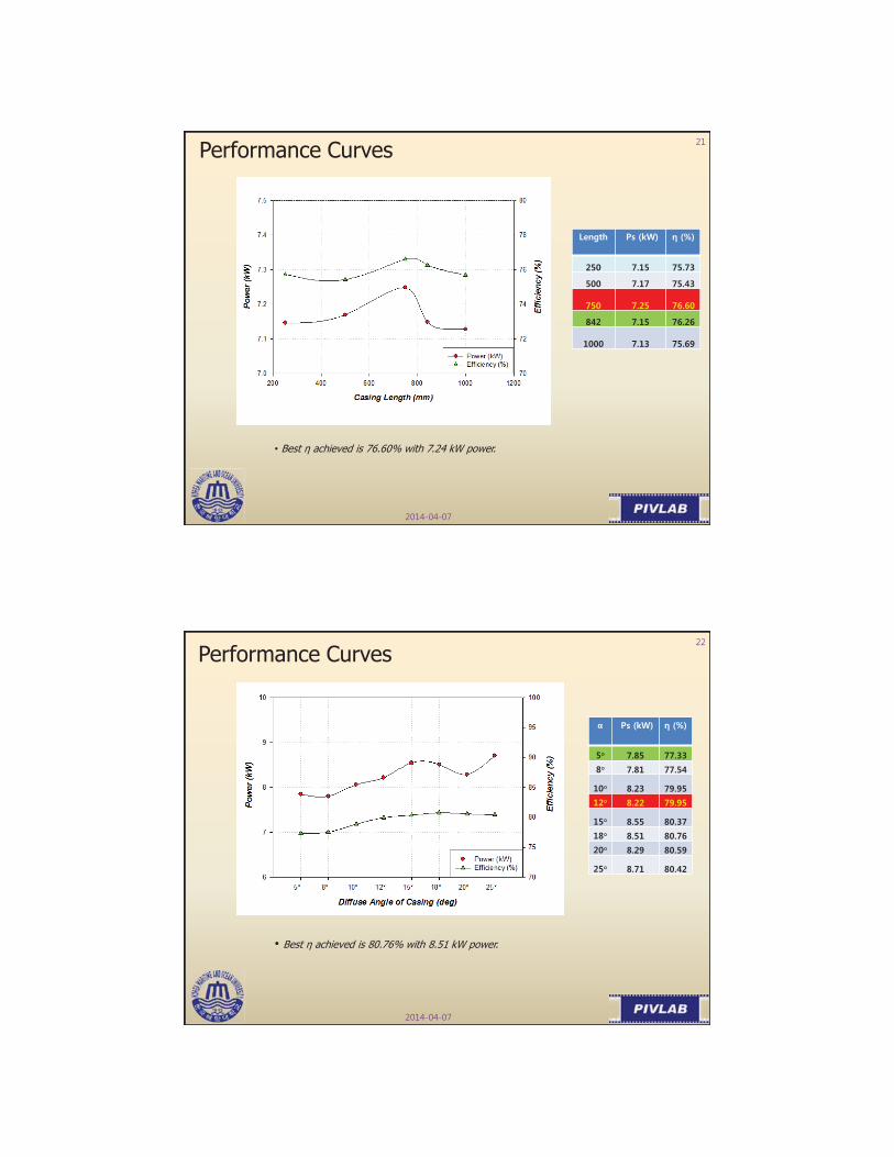
Performance Curves
• Best η achieved is 76.60% with 7.24 kW power.
Performance Curves
α
°°
°°
°°°
°
• Best η achieved is 80.76% with 8.51 kW power.
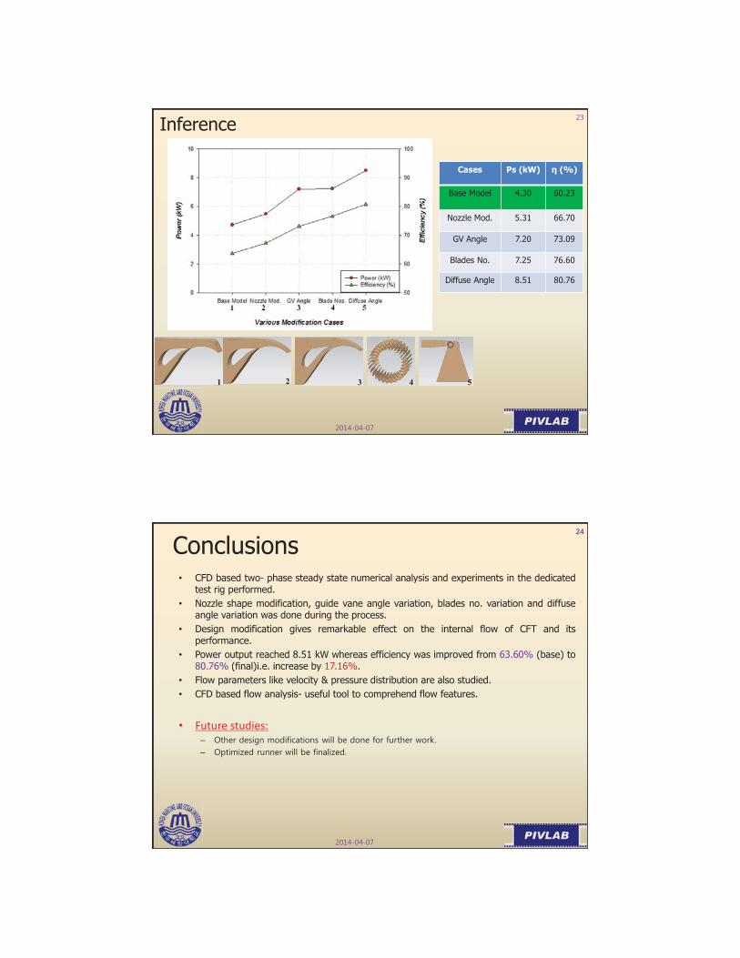
Inference
Cases Ps (kW) η (%)
Base Model 4.30 60.23
Nozzle Mod. 5.31 66.70
GV Angle 7.20 73.09
Blades No. 7.25 76.60
Diffuse Angle 8.51 80.76
1 532 4
Conclusions• CFD based two- phase steady state numerical analysis and experiments in the dedicated
test rig performed.• Nozzle shape modification, guide vane angle variation, blades no. variation and diffuse
angle variation was done during the process.• Design modification gives remarkable effect on the internal flow of CFT and its
performance.• Power output reached 8.51 kW whereas efficiency was improved from 63.60% (base) to
80.76% (final)i.e. increase by 17.16%.• Flow parameters like velocity & pressure distribution are also studied.• CFD based flow analysis- useful tool to comprehend flow features.
• Future studies:––