Embed Size (px)
Citation preview

44
MEMORANDUM REPORT ARBRL-MR-02925
THE HISTORY OF THE QUANTITY DISTANCE
TABL'S FOR EXPLOSIVE SAFETY
Ona R. Lyman
U June 1979 -
US ARMY ARMAMENT RESEARCH AND DEVELOPMENT COMMANDBALLISTIC RESEARCH LABORATORY
ABERDEEN PROVING GROUND, MARYLAND
Approved for public release; distribution unlimited.
I " ,
r mm~ m I~l mlm ii

Destroy this report when it is no longer needed.Do not return it to the originator.
Secondary distribution of this report by originatingor sponsoring activity is prohibited.
Additional copies of this report may be obtainedfrom the National Technical Information Service,U.S. Department of Commerce, Springfield, Virginia22161.
I
The findings in thi- report are not to be construed asan official Department of the Army position, unlessso designated by other authorized documents.
Tha usae )O lpade nw or mnufauturers' mI nha in tiii repom,doe not 1,onstituto indoreement of an oonwrial proaucc.

UNCLASSIFIEDSECURITY CLASSIFICATION OF THIS PAGE (When Dots Entorod)
REPORT DOCUMENTATION PAGE BEFORE COMPLETING FORM
I. REPORT NUMBER . GOVT ACCESSION NO. 3. RECIPIENT'S CATALOG NUMBER
Memorandum Report ARBRL-MR-02925
4. TITLE (andSubtitle) S. TYPE OF REPORT & PERIOD COVERED
THE HISTORY OF THE QUANTITY DISTANCE TABLES FinalFOR EXPLOSIVE SAFETY
6. PERFORMING ORG. REPORT NUMBER
7. AUTHOR(e) 8. CONTRACT OR GRANT NUMBER(&)
Ona R. Lymar,
9. PERFORMING ORGANIZATION NAME AND ADDRESS 10. PROGRAM ELEMENT. PROJECT, TASK
U.S. Army Ballistic Research Laboratory AREA& WORK UNIT NUMBERS
(ATTN: DRDAR-BLT) N/AAberdeen Proving Ground, MD 21005
I I. CONTROLLING OFFICE NAME AND ADDRESS 12. REPORT DATEU.S. Army Armament Research and Development Command JUNE 1979U.S. Army Ballistic Research Laboratory IS. NUMBER OF PAGESATTN: DRDAR-BL) 24berdeen Proving Ground. MD 21005
14. MONITORING AGENCY NAME & ADDRESS(II different from Controli|ng Office) IS. SECURITY CLASS. (of this report)
UNCLASSIFIEDISa. DECLASSIFICATION/DOWNGRADING
SCHEDULE
IS. DISTRIBUTION STATEMENT (of this Report)
Approved for public release, distribution unlimited.
17. DISTRIBUTION STATEMENT (of the abstract entered In Block 20, It different from Report)
18. SUPPLEMENTARY NOTES This work was supported in part by the Safe Transport ofMunitions (STROM) Program of che Military Traffic Management Command.
NOTE: English units are used throughout this report to make comparison to olderdata easier and place less burden on the readers.
IS. KEY WORDS (Continue on reverse side It necessary end Identify by block number)
Explosive SafetyQuantity-DistanceHistory of Explosive Safety
A. ABSTRACT (C Item - ,evem ab N..eeesmy aid Ieuly by block numbet) (mba)he history of the quantity-distance tables for explosive safety is traced from
its inception to the present. Comparisons are made to alternative approachesused by NATO and other countries. There exist only minor differences in safetydistances at this time. U.S. distances are more conservative for quantitiesless than 1000 lbs and less conservative for larger quantities. Projections arealso made as to the effect of packaging changes, and containerization ofammunition shipments on future explosive safety standards.,,
FOM 1473 EDITION OF I NOV 65 IS OBSOLETE UNCLASSIFIED
SECURITY CLASSIFICATION OF THIS PAGE (When Date Entered)

TABLE OF CONTENTS
Page
LIST OF ILLUSTRATIONS ...... ................... .... 5
I. INTRODUCTION .... ...... ....................... 7
II. QUANTITY-DISTANCE TABLES .... .... ................. 7
III. HISTORICAL BACKGROUND .I......... ...... ... 10
IV. CURRENT STATUS OF QUANTITY DISTANCE TABLES .......... ... 17
I V. PROJECTIONS ........ ....................... ... 20
DISTRIBUTION LIST ......... ..................... 23
3 '

LIST OF ILLUSTRATIONS
Figure Page
1. 1915 Inhabited Building Distance Curves with DataPoints on Which They were Based ................ 12
2. 1915 Inhabited Building Distance with Data Pointscor Some Large Accidents ... .............. .... 13
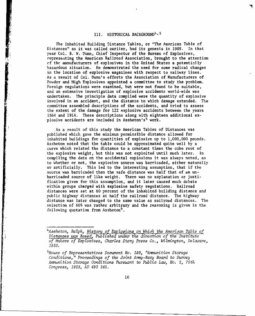
3. Comparison of 1977 Inhabited Building Distance toStructural Failure Distances Calculated by FalconPressure-Impulse Loading Technique .. .. .. ... .... 16
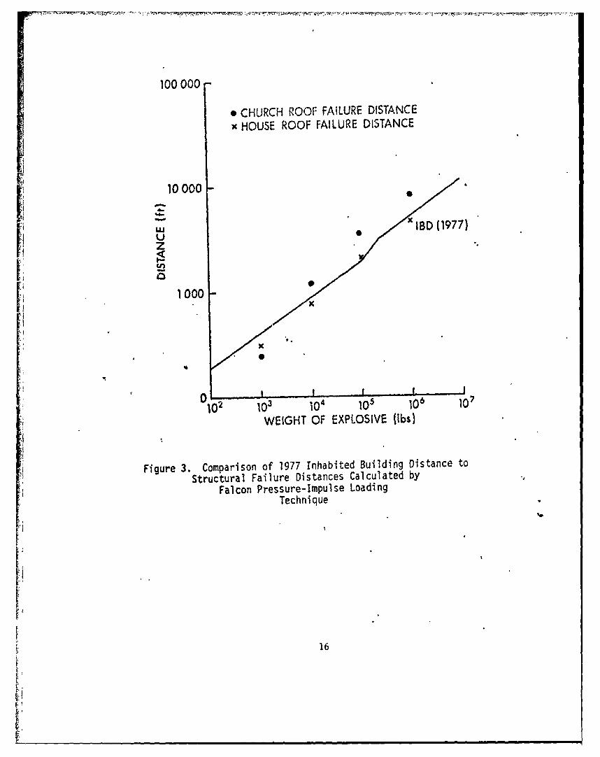
4 4. Comparison of 1977 Public Traffic Route Distance toOverturning Distance for Three Vehicles ComputedUsing Falcon Pressure-Impulse Loading ......... ... 18
5. Comparison of the NATO and U.S. 1977 InhabitedBuilding Distance. Also shown is the 1915 AmericanTable of Distance for a barricade source ..... .... 19
[
'i
Iw m m

I. INTRODUCTION
The Ballistic Research Laboratory (BRL) is investigating the mech-anisms for initiation of detonation of stored munitions. The goal ofthis effort is to reduce the vulnerability of stored munitions, and pre-vent or reduce the probability of propagation of explosion between ad-jacent munitions stores. Application of the techniques developed willrange from small quantities, such as might be fo, md in armored vehiclesto larger quantities encountered in. shipment, oT in storage depots. Aspart of this program an investigation has been made of the source anddevelopment of quantity-distance regulations as defined in AMCR-385-100 1
and TM 9-1300-2062. It is the results of this investigation which willbe reported here.
II. QUANTITY-DISTANCE TABLES
There are a number of different quantLty-distance tables, the appli-cation of which depend on the nature of the potential threat,.and the de-gree of protection required. Different nations have differing standardsto be met, but there is a trend toward agreement on standards. This isexemplified by the recent adoption (1977) of the United Nations classi-fication system by the United States, United Kingdom and many NATO coun-tries. For the US Army, ammunition and explosives are classified on thebasis of their reactions to specified initiating influences as describedin TB 700-23.
The classification system recommended for international use by theUnited Nations consists of nine classes for dangerous goods with ammuni-tion and explosives inciuded in UN class 1, explosives. Class 1 explo-sives are subdivided into four parts as follows. Class 1.1 representsexplosives and ammunition which when stored or shipped with only small
separation distance between items, and may detonate "en masse". Class1.2 is for fragment producing cased explosives, such as projectiles.This class is further subdivided into four subclasses dependent on therange of the fragment threat in feet, i.e., 400, 800, 1200, or 1800feet. This is designated as 1.2 (04), 1.2 (08), 1.2 (12) or 1.2 (18).Class 1.3 il for materials which represent a severe fire threat. Class1.4 is for .-terials which represent a moderate fire threat. Table Ishows the UN hazard classes with the appropriate conversion from thesuperceded US classification system. This table was extracted fromAMCR 385-1001 Change 3, dtd 4 October 1977, Chapter 19.
IUS Army Material Command Regulation 385-100, with Change 3, dated
4 October 19?7.2 US Army Technical Manual TM 9-1300-206, dated August 1973.3TB 700-2, "Explosives Hazard Classification Procedures," with Change
1, dated May 1967.
7

Table I. Conversion From Superceded US HazardClassification System to UNO System
Supereeded UNO HazardClass Class
7 1.1 Mass detonation withpossible fragment threat
6 1.2 (18) Non mass detonating5 1.2 (12) with most fragments4 1.2 (08) falling within the3 1.2 (04) d stance indicated
2 1.3 Mass fire
1 1.4 Moderate fire
The common quantity-distance tables are listed below with theirdefinitions as they are given in AMCR 385-1001, Chapter 17.[ *Inhabited Building Distance. This distance is the minimumpermissible distance allowed between a quantity of explosives and anybuilding inhabited by the public or where people are accustomed toassemble, both within and outside government establishments. Land out-side the boundaries of government installations is included as a possiblesite for inhabited buildings. This minimum distance provides a highdegree of protection against structural damage based on blast or shockwave effects to frame or masonry buildings. It does not provide pro-tection against glass breakage. Personnel injury from flying glassfragments is a possibility.
* Public Traffic Route Distance. This distance is the minimumpermissible distance between an explosives site and public highways orrailroad lines. It is 60% of the inhabited building distance. Thelesser distance is based on the greater resistance of rail and roadvehicles to blast effects. It is additionally reasoned that safety isnot compromised because these items are only exposed for limited periodsas they pass by the explosive site.
* Intraline Distance. This is the minimum permissible distancebetween two buildings within one operating explosive/ammunition produc-tion line. The purpose of the intraline distance is to prevent thepropagation of explosions by blast effects between buildings. Separationof service magazines is an example. Distances are based on the largerquantity of explosives involved in either building.
9 Magazine Distance. This is the minimum permissible distancebetween storage magazines, and is based on the type of magazine and thequantity of explosive involved. It is designed to prevent prcpagationof explosives by blast, and provides reasonable protection against

propagation by fragment impact. It does not preclude severe structuraldamage to magazines adjacent to a magazine suffering an accidentalexplosion.
. Fragment Distance. This distance applies to specific explosiveitems which generate hazardous fragments, such as fragmenting projectilesand heavily cased explosives. For the specified distance thc fragmentdistribution and energy is, less than one fragment of energy 58 ft-lbsper 600 square feet, (78 Joules per 56 m2). 1is distance applies toclass 1.2 items with distances as previously described of 400, 800, 1200and 1800 feet. This distance also is the inhabited building distancefor class 1.2 items and is designated to protect individuals in the openfrom fragment threats.
Excluding the fragment distance, which is specific for each munition,the remairing distances each correspond to a specific scale distanceZ = R/WI/3, where R is the distance in feet from the explosive and W isthe weight of the explosive in pounds. The scale distance can be re-lated to a specific value of overpressure. Table II gives the 1977scaled distances for each of the above defined quantity distances usedby the United States, and the approximate value of the side-on-pressureF,' associated with each scale distance.
Table II. Scale Distance and Side-On-Pressure ForSpecified Quantity-Distance Categories
Quantity Scale Side-On-PressureDistance Distance p.s.i.
Inhabited Building
1 to 100,000 lbs 40 - 1.1100,000 to 250,000 lbs 40 -50250,000 to 1,500,000 lbs SO 0.93
Public Traffic Route
1 to 100,000 lbs 24 ~ 1.8100,000 to 250,000 lbs 24-30250,000 to 1,500,000 lbs 30 - 1.4
Intraline 18 - 2.5
Magazine Distance(dependent of type I.i Ii ~ 700 5.3of magazine)
9
III. HISTORICAL BACKGROUND4 ,5
The Inhabited Building Distance Tables, or "The American Table ofDistances" as it was called earlier, had its genesis in 1909. In thatyear Col. B. W. Dunn, Chief Inspector of the Bureau of Explosives,representing the American Railroad Association, brought to the attentionof the manufacturers of explosives in the United States a potentilyhazardous situation. He demonstrated the need for some radical changesin the location of explosive magazines with respect to railway lines.As a result of Col. Dunn's efforts the Association of Manufacturers ofPowder and High Explosives appointed a committee to study the problem.Foreign regulations were examined, but were not found to be suitable,and an extensive investigation of explosive accidents world-wide wasundertaken. The principle data compiled were the quantity of explosiveinvolved in an accident, and the distance to which damage extended. Thecommittee assembled descriptions of the accidents, and tried to assessthe extent of the damage for 122 explosive accidents between the years1864 and 1914. These descriptions along with eighteen additional ex-plosive accidents are included in Assheton's 4 work.
As a result of this study the American Tables of Distances waspublished which gave the minimum permissible distance allowed forinhabited buildings for quantities of explosive up to 1,000,000 pounds.Assheton noted that the table could be approximated quite well by acurve which related the distance to a constant times the cube root ofthe explosive weight, but this was not exploited until much later. Incompiling the data on the accidental explosions it was always noted, asto whether or not, the explosive source was barricaded, either naturallyor artificially. This led to the interesting assumption, that if thesource was barricaded then the safe distance was half that of an un-barricaded source of like weight. There was no explanation or justi-fication given for this assumption, and it later caused much debatewithin groups charged with explosive safety regulations. Railroaddistances were set at 60 percent of the inhabited building distance andpublic highway distances at half the railroad distance. The highwaydistance was later changed to the same value as railroad distances. Theselection of 60% was rather arbitrary and the reasoning is given in thefollowing quotation from Assheton4 .
4Assheton, Ralph, History of Explosions on Which the American Table ofDistances was Based., Published under the direction of the Instituteof Makers of Explosives, Charles Story Press Co., Wilmington, Delaware,1930.
5louse of Representatives Document No. 199, "Ammunition StorageConditions," Proceedings of the Joint Army-Navy Board to SurveyAmmunition Storage Conditions Pursuant to Public Law, No. 2, 70thCongress, 1928, AD 493 245.
10

... after as careful a consideration as possible,
it was concluded that reasonably safe distancesfrom railroads were provided by taking 60% of theinhabited building distances, the reasons for theconclusion being:
The lesser height and small area of railroadcars exposed to resist concussion, as comparedwith buildings.
The fact that while a building is stationaryand subject to any risk constantly, the presenceof a train is only temporary."
It is interesting to note that the wording in AMCR 385-1001, Chapter 17,paragraph 3 is very nearly identical to the above quotation.
The American Table of Distances was established in 1915. The stateof New Jersey adopted them as state law in 1925 and the United StatesGovernment adopted them in 1928 following the Lake Denmark accident5,which incidently marked the beginning of what now is the Dept. of DefenseExplosive Safety Board. The most remarkable aspect of this table wasthat in spite of the large scatter in the data (see Figure 1), and thereliance that had to be placed on subjective accounts of the accidents,often several years old; these tables are remarkably close to modernaccepted values. The tables remained unchanged for many years. In factthey are given exactly as published in a 1942 US Army Ordnance SchoolText 6 and in a 1960 explosives handling manual7 .
In 1945 Col. C. S. Robinson who was attached to the Army/NavyExplosive Safety Board published a report8 in which he questioned theaccuracy of the inhabited building distance tables. His primary concernwas for large quantities of explosives. He believed the distancesspecified were inadequate. He was also concerned that modern explosives,being more energetic per unit weight, might also make the distancesspecified too short for safety. His concern was based primarily ondamage xesulting from accidents involving large quantities of explosives,and the fact that World War II mobilization resulted in large quantitiesof munitions being stored in various port areas. Figure 2 shows theAmerican Table of Distances with data points that were the basis of his
60rdnance School Text OS 9-18, Vol. 5, Ammunition General, Part IXStorage, November 1942.
7ARMTC-TR 60-11, Manual for Handling Explosives, Anmnition and SolidPropellants, Section I, pages 1-24. Contractor Report compiled byPan American World Airways. AD 710 180.8Col. Clark S. Robinson, Army-Navy Explosive Safety Board, Technical
Paper Number 1, "The Present Status of the American Table ofDistance, " 1 July 1945.
11

10000
10000
-" UNBARRICADED"-.- +'+ SOURCE,4-w +
+ BARRICADEDU'+ SOURCE
1000- + .
1O, 106
WEIGHT OF EXPLOSIVE (Ibs)
Figure 1. 1915 Inhabited Building Distance Curves withData Points on Which They Were Based
12

100000HASTINGS +
PORT CHICAGO+
STEINFELD10000 - +4
HALIFAXSTO +LAKE DENMARK
wETOu 1915zI<-- UNBARRICADED
1000 -1915BARRICADED
102 _0 3 104 105 106
WEIGHT OF EXPLOSIVE (Ibs)
Figure 2. 1915 Inhabited Building Distances with DataPoints for Some Large Accidents
[3
13

concern. Adding to Col. Robinson's concern may have been the accidentsat Port Chicago and at Hastings the previous year. Both involved largequantities of Torpex, which was known to be more sensitive than TNT andto have a greater air blast effect. Col. Robinson also questioned theefficacy of barricades at the source in reducing safe distances in thisreport. He is largely responsible for the work that was initiatedfollowing World War II to increase the knowledge and understanding ofexplosives and their effects.
In the period following the end of World War II extensive explosiveblast research was undertaken at many government laboratories. Asshetonhad noted in 1930 that the American Table of Distances could be approxi-mated by a constant times the cube root of the explosive weight, Exten-sive testing and measurement of blast pressures under carefully con-trolled conditions validated this concept. Protection from the effectsof blast are now related to a specific scaled distance, as indicated inTable II. Assheton's 1930 value for barricaded explosive sites was 35.The 1977 value for inhabited building distance is 40 for quantities ofexplosive up to 100,000 lbs and 50 for quantities in excess of 250,000lbs.
The effectiveness of barricades in reducing blast pressures was atopic that received a great deal of attention in the twenty year periodfollowing World War II. Col. Robinson had questioned the efficacy ofbarricades in his 1945 paper8 and dealt more extensively with the topicin his book9 . The Armed Services Explosive Safety Board sponsored alarge amount of work to produce data addressing the problem. Thedifficulty encountered in removing barricaded distances from the inhabitedbuilding distance tables is illustrated in a presentation to the ArmedServices Explosive Safety Board by the Defense Atomic Support Agency in196610. In addition to the data and conclusions presented, thi3 reportincludes a transcript of the discussions following each presentation.The reluctance to abandon Ihe concept that barricades at the source canreduce safe distances for inhabited buildings is clearly evident. Asecond DASA paper11 published in 1968 gives a very good summary of theavailable data and a very complete bibliography of pertinent publica-tions. Barricades were proven to be less effective than previouslysupposed at distances more than 5 to 8 times the barricade height. Asa result the barricaded distance values were eliminated from inhabited9Col. Clark S. Robinson, Explosions. their Anatomy and DestructivenessMcGraw Hill, New York, 1944.
10"Barricaded vs Unbarricaded Blast Pressure-Distance Relationships,"a Presentation to the Armed Services Explosive Safety Board by theDefense Atomic Support Agency, 12 J1ly 1966, presenters were:Jack R. Kelso, DASA; William S. Filter, Naval Ordnance Laboratory;and Kenneth Kaplan, URS Corp., AD 835 629.
1 1 URS 677-4R, DASA 2014, "Effectiveness of Barricades: Review of Basicinformation," K. aplan and V. W. Davis, URS Corp., June 1968, pre-pared for Defense Atomic Support Agency, AD 837984.
14

building distance tables.
In an attempt to better predict and quantify blast damage to specifictargets and target elements, generally in a vulnerability analysis con-text several authors have incorporated impulse loading with pressureloads to predict a specified damage level. In general curves represent-ing a constant level of damage can be obtained in the pressure-impulseplane. Johnson1 2 and Baker1 show several examples, the former fortotal targets and the latter for structural elements. In every case theresponse of the target and failure mode must be specified. Sewel 1 4
reported a similar technique in 1964 and more recently Schumacker andCummings 15 have presented a pressure-impulse blast damage mode. FalconResearch and Development Co.1 6 under contract to the Armed Services Explo-sive Safety Board developed models of blast response for ten specifiedtargets. The targets were selected as typically those encountered inquantity-distance tables i.e., a house, public buildings, magazines,
aircraft, and vehicles. The models were dynamic interaction models andconsidered both elastic and plastic deformation of the principle struc-tural elements of each target, and specified acceptable damage levels.A computer program was generated to handle the computations. Wherepossible, comparison is made to actual test data. Calculations were madefor five charge weights ranging from 1000 lbs to 9,000,000 lbs. Theresulting isodamage curves in the pressure-impulse plane are hyperbolicand similar to those of Johnson12 and Baker 1 3.
Figure 3 shows a comparison of the predicted response of a splitlevel ranch style home, and an A frame church structure to current in-habited building distance curves. The specified acceptable damage levelfor the house is the cracking, but not breaking of the rafters (2" x 8"x 17 feet long, 16 inches on center with 1/2" plywood roof). The speci-fied acceptable damage level for the church was the cracking, but notbreaking of laminated roof trus~t~s (7.5" x 16" x 39 feet long, 15 feeton center with a roof of 4" x 8" tongue and groove planks). As can beseen from Figure 3 the house data points fall very nearly on the in-habited building distance curve, but the data points for the churchindicate inadequate protection for charge weights in excess of 5000 lbs.
12Johnson, 0. T., "A Blast-Damage Relationship," BRL R 1389, BallisticResearch Laboratory, September 1967, AD 389 909.
1 3Baker, W. E., et al, "Workbook for Predicting Pressure Wave andFragment Effects of Exploding Propellant Tanks -nd Gas StorageVessels," NASA CR-134906, November 1975.
I4Sewell, R.G.S., "A Blast Damage Criterion," US Naval Ordnance TestStation, China Lake, CA, NOTS TP 3426, March 1964, AD 349335.
1"5S';humaker, R. N. and Cummings, B. E., "A Modified Pressure-Inrpulse
Blast Damage Model," Ballistic Research Laboratory BRL MR 2724,January 1977. (AD #A036196)
"bCustard, G. M., Donahue, J. D., and Thayer, J. R., "Evaluation of
Explosive Storage Safety Criteria," May 1970, prepared for ArmedServices Explosive Safety Board, AD 871 194.
'5
100000
* CHURCH ROOF FAILURE DISTANCE
x HOUSE ROOF FAILURE DISTANCE
10000
wU KBD (1977)
zI-
1 000x
102 1o 4 10 10 10,WEIGHT OF EXPLOSIVE fIbs)
4 Fgur 3.Comparison of 1977 inhabited Building Distance toStructural Failure Distances Calculated by
Falcon Pressure-Impulse LoadingTechnique
16

Figure 4 is a similar comparison between calculated safe distances(targets are not overturned) for a bus, a pickup truck with camper, anda house trailer all on a highway, and public traffic route distancescurrently in effect. In this case the bus, which is the more resistantto overturning of these targets. has a safe distance nearly coincidentwith public traffic route distances, except for very large charge weights.The other two targets are likely to be overturned at the public trafficroute distances. This demonstrates how important the target responseand failure mode are to calculating safe distances by this technique.Because the target response is so important to the calculation of safedistances, and because of the diversity of targets that must be pro-tected at inhabited building distances and at public traffic routedistances it is unlikely that this technique, which requires computercalculations will have any marked effect on the quantity distance tables.Exceptions might well be made however for those situations where largequantities of explosive are stored or where the public is encroachingon territory adjacent to large storage sites. Other possible exceptionsmight be special construction at inhabited building distances which byits nature may be more vulnerable to blast damage, for example a curtainwall building with large expanses of glass windows.
IV. CURRENT STATUS OF QUANTITY DISTANCE TABLES
The current US Inhabited Building Distances are compared to the 1977NATO standards"7 in Figure 5. As can be seen the US values are moreconservative for quantities less than 1000 lbs, and less conservativefor larger quantities. For example at 10,000 lbs NATO standards require1206 feet compared to 865 feet to meet US standards and for 100,000 lbsthe values are 2600 feet NATO vs 1855 feet US. (NOTE: NATO standardsare in metric units.
1/3D = 22.2 Q for > 4500 kg
D = 5.5 Q1/2 for < 4500 kg
where D is in meters and Q is the weight of the explosive in kg).
The NATO standards 17 for inhabited buildings are based on workreported by the United Kingdom1 in 1959. In this work standards aremultiples of a quantity Rb which stands for the radius of B type damage."B" damage is defined as: Such severe damage as to require demolition.The data were derived from bomb damage by air blast to buildings duringWorld War II. Rb in terms of explosive weight is given by the formula:
17ManuaZ on NATO Safety PrincipZes for the Storage of Ammunition and
Explosives, 1977, AC/258-D/258.
"8Notes on the Basis of UK Outside Safety Distances for ExplosivesInvolving the Risk of Mass Explosion," March 1959, AD 221 164.
17

100 000-0 o HOUSE TRAILER OVERTURNING DISTANCE
a PICKUP-CAMPER OVERTURNING DISTANCE+ BUS OVERTURNING DISTANCE
0
10000 a
0
Uz +
o PUBLIC TRAFFIC, "" ROUTE DISTANCE1 000- ,. . 977
1000-
0 I i 1
102 101 100 106
WEIGHT OF EXPLOSIVE (ibs)
Figure 4. Comparison of 1977 Puulic Traffic Route Distanceto Overturning Distance for Three Vehicles Computed
using Falcon Pressure-Impulse Loading
18

100 000
10000NATO 1977
uU US 1977U
z-..-..- ATD 1915
1000
0-
0O1 106 107
WEIGHT OF EXPLOSIVE (Ibs)
Figure 5. Comparison of the NATO and U.S. 1977 Inhabited BuildingDistances, Also shown is the 1915 American Table
of Distance for a barricaded source.
19

14 W1 / 3
where Rb is in feet and W is the explosive weight in lbs. Inhabitedbuilding distances were then set at 4Rb. For explosive weights in
excess of about 10,000 lbs the inhabited building distance is approxi-mated by 4 Rb = 56 W . The above formula was the NATO standard in197019. Except for the change in units the 1977 NATO standard is thesame above 10,000 lbs of explosive. For lesser quantities the expres-sion now used is shown below in both English and metric units.
R = 12 W1 /2 R in feet W in lbs.
D = 5.5 Q1/2 D in meters Q in kilograms.
Intermagazine distances and intraline distances appear to be aboutcomparable between the US and NATO standards, although NATO intralinedistances are slightly more conservative. An exact comparison isdifficult because of differences in definitions and descriptions ofdonor and acceptor sites.
V. PROJECTIONS
In the author's opinion, there will be little change in the quantitydistance tables. The distances for blast damage to general classes oftargets are well established from both theoretical and experimentalprograms. It appears likely that the U.S. and NATO countries will cometo an agreement on a mutually acceptable standard, probably in metricunits. Donor and acceptor site definitions and descriptions will alsoprobably be standardized. Somewhat less likely, but still possible, isa world wide standard through the UNO analogous to the recently adoptedexplosive classification system (see Reference 1, change 3, datedOctober 77).
There exist current programs, within the military explosive researchcommunity, which have the potential to result in a severe impact onammunition storage criteria. The programs do not negate the establishedquantity distance tables. What they do hope to accomplish is to providetechniques to limit the amount of explosive allowed to participate inan explosive accident. This work is an extension of a concept contained
19NATO Safety Principles for the Storage of Ammunition and Explosives,1970, AD 876 078.
20

in Reference 5 - a report by the Joint Army-Navy Board to Congress.They said, "It is not the total amount in the depot that should be theguide, but rather the amount in any one pile or building, the manner inwhich it is stored, and the kinds of explosive that are stored in thevicinity." Current programs seek to extend this concept so that thequantity of ammunition that is allowed to participate in an accidentalexplosion is limited to some small portion of the ammunition in thestack or storage facility, and so that the reaction violence of themunitions that do participate is minimized. Two major programs support-ing these research efforts are Containerized Shipment and Storage ofAmmunition 20 (COSSA) and Safe Transport of Munitions21 (STROM).
The COSSA study is a result of the projected shift in sea liftcapability from break bulk cargo ships to a containership fleet.Alt'ough the COSSA study is primarily a study of logistics problems,there is a significant impact on safe storage of ammunition. The use ofcontainers for ammunition shipment provides the packaging engineer witha fixed volume and maximum weight with which to work. These constraints,along with maintaining realistic logistic efficiency, still provide theopportunity for packaging at least some munitions in a manner which canlimit the participation to a portion of the munitions stored in a
container and reduce the violence of secondary reactions. Thisopportunity has not, as yet, been exploited.
The STROM program is a two pronged attack. First the causes ofaccidental detonation of munitions during transport are being isolatedand eliminated to the extent possible, and second packaging and ammuni-
tion design are being inv igated to reduce round to round and containerto container communication, and reduce the violence of non-designinitiated reactions.
There are four principal research areas which derive at leastpartial support from these programs which have the potential to makesignificant impact on ammunition storage criteria. They are as follows:(1) research on the mechanisms of fragment impact initiation of casedexplosives, (2) the use of buffering material to reduce round to roundcommunication of detonation, (3) modification of munitions design toreduce the violence of reaction in nondesign initiation modes, and(4) modification of explosive fills to make ammunition less susceptible
20"Containerized Shipment and Storage of Ammunition," Final Draft,Sep 76, ACN 22194, DA, HDQ TRADOC, Fort Monroe, VA., USA LogisticCenter, Fort Lee, VA.
21 "Safe Transport of Munitions," Study Plan, revised 7 Jan 77, Militarj
Traffic Management Command Transportation Engineering Agency, NewportNews, VA 23606.
21

to nondesign initiation. The work of Howe 22'2 3 at the BallisticResearch Laboratory is an example of research in the first two areas.The phenomena of interround communications and initiation mechanisms arediscussed and the effectiveness of various buffering techniques aredocumented in these works. Mr. Pakulak24 at Naval Weapons Center, ChinaLake, has demonstrated the effectiveness of various liner materials, forthe Mark 80 series of bombs, in reducing the violence of reaction re-sulting from cook-off of stacked bombs. He has shown that case rupturecan be made to occur in cook-off tests with these munitions, resultingin explosive burning rather than violent detonation. Continuing basicresearch in explosives and explosive effects within the Army and Navyresearch communities shows promise of providing explosives which areless sensitive to accidental initiation while maintaining their desiredweapon design characteristics.
In summary, it appears that the combination of all these effortswill result, at some future time, in a hazard reduction for many classesof ammunition. Although all these techniques are not applicable to allmunitions, they will generally be applicable to most of the high useitems of ammunition. It seems likely that some munitions currentlyclassified as hazard class 1.1 may be able to be reclassified at 1.2,at least as long as they are transported or stored in a specifiedmanner. The principal constraints for all of the tasks mentioned aboveare that weapon effectiveness must not be compromised, and reasonablelogistics requirements must still be met. These goals seem to beattainable, and while not directly effecting the quantity distance tables,will reduce the number of kinds of munitions currently classed as massdetonable.
22Howe, Philip M., "The Phenomeo logy of Interround Communication andTechniques for Prevention," Ballistic Research Laboratory, ARBRL-TR-02048, Mar 78. (AD #A054373)
Howe, Philip and Collis, David, "Effectiveness of Plastic Shields inPrevention of Propagation of Reaction Between Compartmentalized War-heads," Ballistic Research Laboratory, ARBRL-MR-02827, Arr 78.(AD #B027466L)
24Pakulak, Jack M., "Reduction of Cook-off Hazards," Fifteenth ExplosiveSafety Seminar, Vol. II, Sep 1973, pp 1263-1272.
22

DISTRIBUTION LIST
No. of No. ofCopie Organization Copies Organization
12 Commander 1 CommanderDefense Documentation Center US Army Communications RschATTN: DDC-DDA and Development CommandCameron Station ATTN: DRDCO-PPA-SAAlexandria, VA 22314 Fort Monmouth, NJ 07703
1 Chairman 2 CommanderDOD Explosives Safety Board US Army Missile ResearchRoom 856-C, Hoffman Bldg. I and Development Command2461 Eisenhower Avenue ATTN: DRDMI-RAlexandria, VA 22331 DRDMI-YDL
Redstone Arsenal, AL 35809I Commander
US Army Materiel Development 1 Commanderand Readiness Command US Army Tank Automotive
ATTN: DRCDMD-ST Research 4 Development Cmd5001 Eisenhower Avenue ATTN: DRDTA-ULAlexandria, VA 22333 Warren, MI 48090
I Commander 2 CommanderUS Army Aviation Research US Army Mobility Equipment
and Development Command Research & Development CmdATTN: DRSAV-E ATTN: DRDME-WCP. 0. Box 209 DRSME-RZTSt. Louis, MO 63166 Fort Belvoir, VA 22060
1 Director 2 CommanderUS Army Air Mobility Research US Army Armament Research
and Development Laboratory and Development CommandAmes Research Center ATTN: DRDAR-TSS (2 cys)Moffett Field, CA 94035 Dover, NJ 07801
1 Commander 2 CommanderUS Army Electronics Research US Army Armament Research
and Development Command and Development CommandTechnical Support Activity ATTN: DRDAR-LCMATTN., DELSD-L L. SaffianFort Monmouth, NJ 07703 R. Rindner
Dover, NJ 078011Commander
US Army Harry Diamond Labs 1 CommanderATTN: DRXDO-TI US Army Armament Materiel2800 Powder Mill Road Readiness CommandAdelphi, MD 20783 ATTN: DRSAR-LEP-L
Rock Island, IL 61299
23

DISTRIBUTION LIST
No. of No. ofCopies Organization Copies Organization
3 Project manager, XM-l 4 CommanderTank System David W. Taylor Naval Ship
ATTN: J. W. Roossien Research & Development Ctr28150 Dequindre Street ATTN: Dr. June AmlieWarren, MI 48092 Dr. Shu Ling Wang
Mr. Harry Gray1 Project Manager Mr. Ib Hansen
Container Oriented Bethesda, MD 20084Distribution Systems
5001 Eisenhower Avenue 1 CommanderAlexandria, VA 22333 Naval Surface Weapons Center
ATTN: Tech Lib1 Director Silver Spring, MD 20910
US Army TRADOC SystemsAnalysis Activity 2 Commander
ATTN: ATAA-SL, Tech Lib Naval Weapons CenterWhite Sands Missile Range ATTN: Mr. J. PakulakNM 88002 Mr. R. Sewell
China Lake, CA 935551 Commander
US Army Logistics Command 1 Department of TransportationATTN: ATLC-CFF Federal Railroad AdministrationFort Lee, VA 23801 ATTN: Don Levine
2nd & V Street, SWI Commander Washington, DC 20590
Military Traffic Management
Command 1 CommanderNASSIF Building Transportation EngineeringWashington, DC 20315 Agency
ATTN: A. Ragunas1 Commander 12388 Warwick Boulevard
Berlin Brigade P. 0. Box 6276A'7FN: MAJ R. Miller Newport News, VA 23606
AEBA-GC-PAPO New York 09742 Aberdeen Proving Ground
I Commander Dir, USAMSAANaval Air Systems Command ATTN: Dr. J. SperrazzaATTN: Dr. A. Amster L. SebastianiWashington, DC 20362 DRXSY-MP, H. Cohen
Cdr, USATECOMI Commander ATIN: DRSTE-TO-F
Naval Sea Systems Command Dir, Wpns Sys Concept TeamATTN: Code 03511, C. Pohler Bldg. E3516, EAWashington, DC 20362 ATTN: DRDAR-ACW
24