Embed Size (px)
Citation preview
71:2 (2014) 37-41 | www.jurnalteknologi.utm.my | eISSN 2180–3722 | ISSN 0127–9696
Full paper Jurnal Teknologi
Observation on Solid Propellant Ignition Using High Speed Camera: The Effect of Hot Wire Position on the Combustion Flame Contour Wan Khairuddin Wan Ali, Ang Kiang Long*, Mohammad Nazri Mohd. Jaafar
Transportation Research Alliance (TRA), Faculty of Mechanical Engineering, Universiti Teknologi Malaysia, 81310 UTM, Johor Bahru, Malaysia. *Corresponding author: [email protected] Article history Received : 1 Jul 2013 Received in revised form : 18 Aug 2014 Accepted : 24 Aug 2014 Graphical abstract
Abstract This paper reports on the discovery of unique flame structure of a composite propellant sample under hot wire ignition. The entire combustion process at atmospheric pressure condition was recorded using a high speed camera. Three hot wire orientations were chosen in this experiment for examining their effects on the propellant burning behavior. The results show that the wire orientations are crucial in propellant combustion process, as different flame patterns were observed when the hot wire orientation was altered. This paper provides an important insight into this specific ignition process that can be useful for researchers in the aerospace industry for better design and more realistic simulation results in ignition control. Keywords: Ammonium perchlorate; solid propellant; flame structure; high speed camera imaging
© 2014 Penerbit UTM Press. All rights reserved.
¢1.0 INTRODUCTION Ignition process is one of the key areas in rocket propulsion research either for liquid or solid propellant system. A thin nichrome wire served as hot surface to ignite the hydrogen-oxygen mixtures was reported in Buckel and Chandra [1] experiment. It was important to predict the hydrogen ignition temperature in early 90s as hydrogen appeared to be a promising alternative energy source for both spark-ignition and diesel engines. There was another hot wire ignition experiment on a pressed HMX pellet by Ali et al. [2] where the ignition process of a nickel chromium wire was captured with high speed camera. However, the actual wire location on the pellet surface was not discussed in their report. In more recent years, Paletsky et al. [3] placed a nichrome wire at around 1 mm from the surface of a CL-20 sample and electrically triggered the wire in an argon atmosphere. The combustion process of the CL-20 sample was recorded by commercial camera at a frame rate of 25 Hz. A few other references that reported the use of nichrome wire as igniter are found in [4-6]. Ammonium perchlorate (AP) oxidizer and polymetric binder fuels are typical ingredients found in a composite rocket propellant. AP flame structure in methane flow was studied by Smooke et al. [7] using planar laser induced fluorescence (PLIF) with CO2 laser ignition on AP pellets. Two dimensional, axisymmetric AP diffusion flame images were published in their report. Besides observing the flame structure of an AP oxidizer, two dimensional laminate propellant flames have been studied extensively by researchers in order to validate heterogeneous solid
propellant combustion models. A simple model for diffusion flames of a heterogeneous propellant was briefly discussed by Buckmaster et al. [8]. The limitation of their proposed model was noticeable due to the assumptions that differ from the physical reality: sample surface was assumed to be flat, numerical value for temperature and mass flux were assigned, a single step reaction model was used, etc. Infrared (IR) and ultraviolet (UV) emissions and transmission imaging were used to observe AP based laminate propellant flames, as reported in Fitzgerald and Brewster [9-12], where intrinsic instability was discovered at the fuel binder layer. Burning rate trends of an AP based laminate sample were investigated by Navaneethan et al. [13]. It was found that the AP/binder mixture ratio can influence the sample surface profile due to the leading edge flame during the combustion process. Burning rates increased drastically with higher AP loading in the laminate sample. The effect of AP particle size on the propellant flame structure was further studied by Hedman et al. [14] where bimodal composite samples were ignited with laser beam and high speed PLIF was used in their research. According to literature, split diffusion flame and merged-partially-premixed flame were observed with similar approach by Brewster and Mullen [15] on aluminized AP composite laminate sample. With different experimental setup, ignition with hot stainless steel was reported in Ramakrishna et al. [16] who studied AP based sandwich propellant flame structure. Other than close-up observations on laminate samples as mentioned above, a cylindrical pellet shaped sample was used by Ulas et al. [17] in their experiment in order to understand the
38 Wan Khairuddin, Kiang Long & Nazri / Jurnal Teknologi (Sciences & Engineering) 71:2 (2014) 37–41
combustion behavior of solid propellant. Ignition on the sample surface was also initiated by laser beam, while the combustion process was recorded with high speed camera. Another variation in observation method was reported by Yang et al. [18] using CCD line camera recording the burning characteristic of a pressed pellet sample. In the subject of aluminum reactivity in hot combustion environment, agglomeration process for an alumimized AP composite propellant was studied by Maggi et al. [19]. Metal particles were found to protrude into the flame zone and got ignited. In general, most samples found in the literature were in the form of laminate or sandwich, while literatures reporting flame structure of a cylindrical shape sample was hardly available and limited. Thus, the authors feel the need to revisit the area of flame structure of a composite propellant under ignition initiated by a hot wire. This paper reports on a qualitative 2-dimensional observation on hot wire ignition report. ¢2.0 EXPERIMENTAL DESIGN The ingredients used in the experiments are showed in Table 1. Particle size of AP was characterized with standard sieve of 250 µm and stored in the oven at 60ºC for 24 hours to remove moisture. All the ingredients were weighed using an electrical weighting machine and mixed accordingly in a glass beaker to form the experimental propellant slurry. The slurry was pressed into a cylindrical plastic mould (5 mm diameter, 90 mm length) and stored in an oven maintained at 60ºC for a period of 48 hours. A copper wire was placed inside the cured propellant at a designed location after they were removed from their plastic mould. All samples used in this experiment were not coated with any inhibitor layer.
Table 1 Propellant ingredients and their sources
Propellant ingredient Type Composition (% by mass)
Ammonium perchlorate (AP) (minimum 250 �m) Oxidizer 66
Binder and curing agent Prepolymer 25
Aluminum (Gred AA �m) Fuel 19
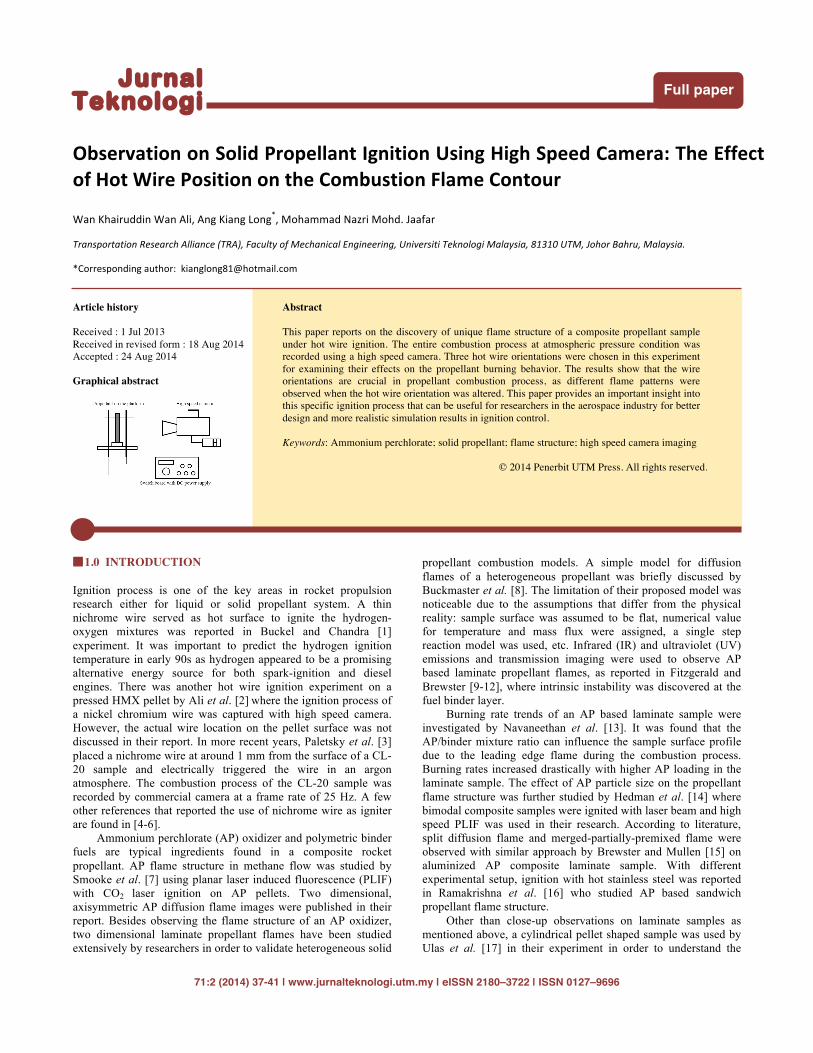
Figure 1 Schematic diagram of the experimental setup
The propellant sample was mounted either vertically or horizontally on an open platform. Three positions of copper wire were studied in this experiment: 1 mm from sample surface, 5 mm from sample surface and center core of the sample. The copper wire was connected to the D.C. power supply with a switch board as shown in Fig. 1. The entire experiment was conducted at
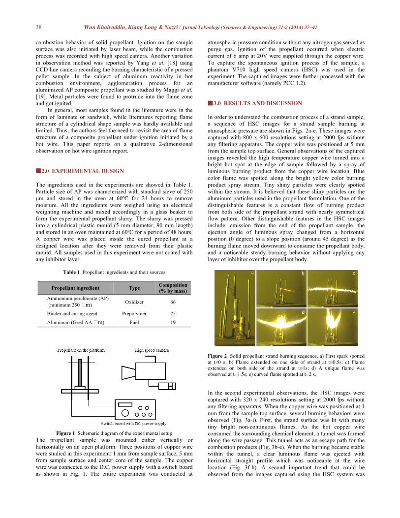
atmospheric pressure condition without any nitrogen gas served as purge gas. Ignition of the propellant occurred when electric current of 6 amp at 20V were supplied through the copper wire. To capture the spontaneous ignition process of the sample, a phantom V710 high speed camera (HSC) was used in the experiment. The captured images were further processed with the manufacturer software (namely PCC 1.2). ¢3.0 RESULTS AND DISCUSSION In order to understand the combustion process of a strand sample, a sequence of HSC images for a strand sample burning at atmospheric pressure are shown in Figs. 2a-e. These images were captured with 800 x 600 resolutions setting at 2000 fps without any filtering apparatus. The copper wire was positioned at 5 mm from the sample top surface. General observations of the captured images revealed the high temperature copper wire turned into a bright hot spot at the edge of sample followed by a spray of luminous burning product from the copper wire location. Blue color flame was spotted along the bright yellow color burning product spray stream. Tiny shiny particles were clearly spotted within the stream. It is believed that these shiny particles are the aluminum particles used in the propellant formulation. One of the distinguishable features is a constant flow of burning product from both side of the propellant strand with nearly symmetrical flow pattern. Other distinguishable features in the HSC images include: emission from the end of the propellant sample, the ejection angle of luminous spray changed from a horizontal position (0 degree) to a slope position (around 45 degree) as the burning flame moved downward to consume the propellant body, and a noticeable steady burning behavior without applying any layer of inhibitor over the propellant body.
Figure 2 Solid propellant strand burning sequence. a) First spark spotted at t=0 s; b) Flame extended on one side of strand at t=0.5s; c) Flame extended on both side of the strand at t=1s; d) A unique flame was observed at t=1.5s; e) curved flame spotted at t=2 s. In the second experimental observations, the HSC images were captured with 320 x 240 resolutions setting at 2000 fps without any filtering apparatus. When the copper wire was positioned at 1 mm from the sample top surface, several burning behaviors were observed (Fig. 3a-i). First, the strand surface was lit with many tiny bright non-continuous flames. As the hot copper wire consumed the surrounding chemical element, a tunnel was formed along the wire passage. This tunnel acts as an escape path for the combustion products (Fig. 3b-e). When the burning became stable within the tunnel, a clear luminous flame was ejected with horizontal straight profile which was noticeable at the wire location (Fig. 3f-h). A second important trend that could be observed from the images captured using the HSC system was

39 Wan Khairuddin, Kiang Long & Nazri / Jurnal Teknologi (Sciences & Engineering) 71:2 (2014) 37–41
that the ejections flows from the tunnel were always in horizontal straight profile. This trend is very similar to the observations made in the first experimental settings (Fig. 2c). As the tunnel became bigger and more portion of propellant strand was consumed, changes of flame profile were noticed. Both straight horizontal flames at the wire location begin to combine into a single “fan” profile when the top of the sample was consumed in the combustion process (Fig. 3i).
Figure 3 Observations on hot-wire firing at 1mm from strand top surface. Images were captured at a) t=0 s; b) t=0.2895 s; c) t=0.3445 s; d) t=0.4190 s; e) t=0.4670 s; f) t=0.5125 s; g) t=1.0825 s; h) t=1.1675 s; i) t=1.7575 s. In order to verify the effect of hot wire position on the flame profile, the ignition was trigged 5 mm from the sample top surface in the third experimental setup. Fig. 4 is a sequence of images captured with 320 x 240 resolutions setting at 1000 fps without any filtering apparatus. A blue colored spark was spotted at the edge of the copper wire location when the igniter was triggered (Fig. 4a). A similar burning behavior was captured in the images where a few blow of luminous flames at the early stage of ignition
(Figs. 4b-e). A group of sparkly dots were also observed within these luminous flames. These blow of luminous flames always occurred at either one side of the sample at any given time before the combustion became stable.
Figure 4 Observations on hot-wire firing at 5mm from strand top surface. Images were captured at a) t=0 s; b) t=0.260 s; c) t=0.288 s; d) t=0.360 s; e) t=0.410 s; f) t=0.500 s; g) t=1.322 s. When the combustion within the tunnel area (copper wire location) became stable, a stream of flame was released horizontally and consumed the rest of the propellant body rapidly. It should be noted that the burning path of the hot flame moved in a hemispherical pattern from edges as it consumed the sample. This burning behavior can be clearly seen in Fig. 4h. However, this burning behavior can only be captured in 2-dimensional images through the current experimental setup. The sample was actually consumed by the combustion flame in 3-dimensional direction, thus some luminous flame was spotted at the back of the sample in Fig. 4i.

40 Wan Khairuddin, Kiang Long & Nazri / Jurnal Teknologi (Sciences & Engineering) 71:2 (2014) 37–41
Figure 4 (continued) Observation on hot-wire firing at 5 mm from strand top surface. Images were captured at h) t=1.330 s; i) t=1.800 s; j) t=2.070 s; k) t=2.475 s.
To ensure detail understanding in the ignition process of strand sample, a copper wire was pierced through the sample as shown in Fig. 5a. The HSC images were captured with 320 x 240 resolutions setting at 1000 fps without any filtering apparatus (Figs 5a-h). As the ignition process was initiated by high temperature copper wire, a luminous flame and non-luminous flame were observed at both ends of the sample. It was a challenging task in spotting the non-luminous flame without observing the path made by the tiny shiny sparks from the hot tunnel. At the given orientation, the flame consumed the sample in a cylindrical pattern within the sample. A luminous flame in conical shape was clearly observed at one end of the sample. Thus, it is reasonable to make an assumption that the hot combustion product was channeled in a self-formed nozzle shaped tunnel after some period of time (Fig. 5g). Before the sample was fully consumed in the combustion process, the yellow colored layer was spotted within the non-luminous flame due to chemical changes in the hot combustion products. The flame spreading rates in this orientation seems faster compared to the earlier two orientations and this phenomenon can be explained with Andoh's [6] argument that there is a pressure difference between the two ends of the holes.
¢4.0 CONCLUSION Experiments were conducted at atmospheric pressure condition to study the flame structure of a composite propellant under hot wire ignition. It is observed that orientation of hot wire in the propellant generate different unique patterns due to the regression rate of the hot energetic material surface. The igniter orientation is an important parameter affecting the propellant burning behavior and burning rates. Careful examination on the igniter orientation during designing a solid propellant rocket motor is crucial for avoiding catastrophic accident results from undesired flame pattern during ignition stage. This paper also provides significant insight for researchers in developing more realistic simulation models in the future.
Figure 5 Hot-wire firing from center position of a horizontal sample. Images were captured at a) t=0 s; b) t=0.024 s; c) t=0.028 s; d) t=0.371 s; e) t=0.495 s; f) t=0.790 s; g) t=1.440 s; h) t=1.525 s.
Acknowledgement The study was conducted under UTM-PHD Zamalah Scholarship and financial support under the Collaboration Project (Program Pembangunan Teknologi Rocket vot no. 68730) between Universiti Teknologi Malaysia, Ministry of Science Technology and Innovation (MOSTI) and Ministry of Higher Education of Malaysia.

41 Wan Khairuddin, Kiang Long & Nazri / Jurnal Teknologi (Sciences & Engineering) 71:2 (2014) 37–41
References [1] J. W. Buckel and S. Chandra. 1996. Hot wire ignition of hydrogen-
oxygen mixtures. Int.J.Hydrogen Energy. 21: 39 – 44. [2] A. N. Ali, S. F. Son, B. W. Asay and R. K. Sander. 2005. Importance of
the gas phase role to the prediction of energic material behavior: An experimental study. Journal of Applied Physics. 97: 063505.
[3] A. A. Paletsky, A. G. Tereshchenko, E. N. Volkov, O. P. Korobeinichev, G. V. Sakovich, V. F. Komarov and V. A. Shandakov. 2009. Study of the CL-20 Flame Structure Using Probing Molecular Beam Mass Spectrometry. Combustion, Explosion, and Shock Waves. 45(3): 286–292.
[4] S. Verna and P. A. Ramakrishna. 2010. Activated charcoal - A novel burn rate enhancer of aluminized composite propellants. Combustion and Flame 157: 1202–1210.
[5] K. K. Kuo and G. Young. 2002. Characterization of combustion behavior of newly formulated NF2-based solid propellants. Proceeding of the Combustion Institute 29: 2947–2954.
[6] E. Andoh, 1997. Effects of Pressure, Initial Temperature, and Propellant Ingredients on Flame-Spreading into a Hole. Combustion and Flame. 108: 397–407.
[7] M. D. Smooke, R. A. Yetter, T. P. Parr and D. M. Hanson-Parr. 2000. Experimental and modeling studies of two-dimensional ammonium percholate diffusion flames. Proceedings of the Combustion Institute. 28: 839–846.
[8] J. Buckmaster, T. L. Jackson and J. Yao. 1999. An Elementary Discussion of Propellant Flame Geometry. Combustion and Flame. 117: 541–552.
[9] R. P. Fitzgerald and M. Q. Brewster. 2007. AP/HTPB laminate propellant flame structure: Fuel-lean intrinsic instability. Proceedings of the Combustion Institute. 31: 2071–2078.
[10] R. P. Fitzgerald and M. Q. Brewster. 2008. Infrared imaging of AP/HTPB laminate propellant flames. Combustion and Flame. 154: 660–670.
[11] R. P. Fitzgerald and M. Q. Brewster. 2004. Flame and surface structure of laminate propellants with coarse and fine ammonium perchlorate. Combustion and Flame. 136: 313–326.
[12] R. P. Fitzgerald and M. Q. Brewster. 2005. Laminate Propellant Combustion (review) 1. Experimental Investigations. Combustion, Explosion, and Shock Waves. 41(6): 693–708.
[13] M. Navaneethan, V. Srinivas and S. R. Chakrarvarty. 2008. Coupling of leading edge flames in combustion zone of composite solid propellants. Combustion and Flame. 152: 574–592.
[14] T. D. Hedman, K. Y. Cho, A. Satija, L. J. Groven, R. P. Lucht and S. F. Son. 2012. Experimental observation of the flame structure of a bimodal ammonium percholorate composite propellant using 5 kHz PLIZ. Combustion and Flame. 159: 427–437.
[15] M. Q. Brewster and J. C. Mullen, 2010. Flame structure in aluminized wide-distribution AP composite propellants. Combustion and Flame. 157: 2340–2347.
[16] P. A. Ramakrishna, P. J. Paul, H. S. Mukunda and C. H. Sohn. 2005. Combustion of sandwich propellant at low pressures. Proceedings of the Combustion Institute. 30: 2097–2104.
[17] A. Ulas, G. A. Risha and K. K. Kuo. 2006. Ballistic properties and burning behavior of an ammonium perchorate/guanidine nitrate/sodium nitrate airbag solid propellant. Fuel. 85: 1979–1986.
[18] R. Yang, H. An and H. Tan. 2003. Combustion and thermal decomposition of HNIW and HTPB/HNIW propellants with additives. Combustion and Flame 135: 463–473.
[19] F. Maggi, A. Bandera, L. Galfetti, L. T. De Luca and T. L. Jackson. 2010. Efficient solid rocket propulsion for access to space. Acta Astronautica. 66: 1563–1573