Embed Size (px)
Citation preview

C-ClassCoupéOwner's Manual
Nur für internen Gebrauch / For internal use only
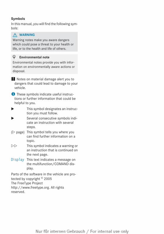
SymbolsIn this manual, you will find the following sym-bols:
G WARNINGWarning notes make you aware dangerswhich could pose a threat to your health orlife, or to the health and life of others.
H Environmental noteEnvironmental notes provide you with infor-mation on environmentally aware actions ordisposal.
! Notes on material damage alert you todangers that could lead to damage to yourvehicle.
i These symbols indicate useful instruc-tions or further information that could behelpful to you.
X This symbol designates an instruc-tion you must follow.
X Several consecutive symbols indi-cate an instruction with severalsteps.
(Y page) This symbol tells you where youcan find further information on atopic.
YY This symbol indicates a warning oran instruction that is continued onthe next page.
Display This text indicates a message onthe multifunction/COMAND dis-play.
Parts of the software in the vehicle are pro-tected by copyright © 2005The FreeType Projecthttp://www.freetype.org. All rightsreserved.
Welcome to the world of Mercedes-BenzBefore you first drive off, read this Owner'sManual carefully and familiarise yourself withyour vehicle. For your own safety and a longervehicle life, follow the instructions and warn-ing notices in this manual. Disregarding themmay lead to damage to the vehicle or personalinjury.The equipment or model designation of yourvehicle may vary according to:RModelROrderRCountry variantRAvailabilityThe illustrations in this manual show a left-hand-drive vehicle. On right-hand-drive vehi-cles, the layout of components and controlsdiffers accordingly.Mercedes-Benz is constantly updating itsvehicles to the state of the art.Mercedes-Benz therefore reserves the rightto introduce changes in the following areas:RDesignREquipmentRTechnical featuresThe equipment in your vehicle may thereforediffer from that shown in the descriptions andillustrations.The following are integral components of thevehicle:ROwner's ManualRService BookletREquipment-dependent supplementsKeep printed copies of the documents in thevehicle at all times. If you sell the vehicle,always pass the documents on to the newowner.
i You can get to know the important fea-tures of your vehicle in the interactive Own-er's Manual on the Internet at:http://www.mercedes-benz.de/betriebsanleitung
The technical documentation team atDaimler AG wishes you safe and pleasantmotoring.
2045843783Z102 É2045843783Z102{ËÍ

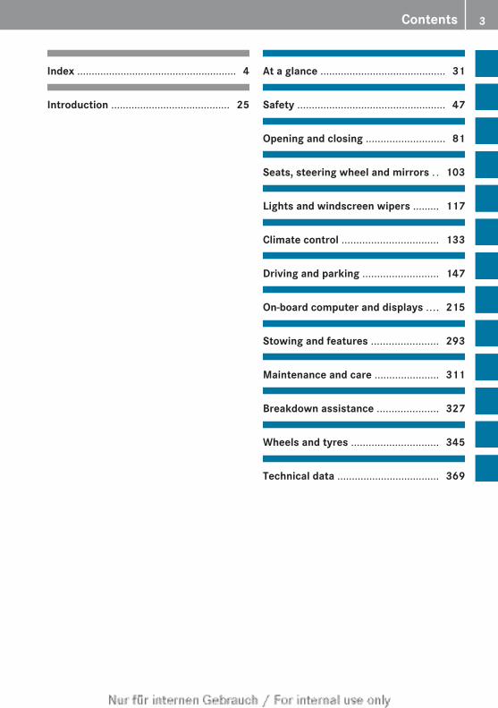
Index ....................................................... 4
Introduction ......................................... 25
At a glance ........................................... 31
Safety ................................................... 47
Opening and closing ........................... 81
Seats, steering wheel and mirrors . . 103
Lights and windscreen wipers ......... 117
Climate control ................................. 133
Driving and parking .......................... 147
On-board computer and displays .... 215
Stowing and features ....................... 293
Maintenance and care ...................... 311
Breakdown assistance ..................... 327
Wheels and tyres .............................. 345
Technical data ................................... 369
Contents 3
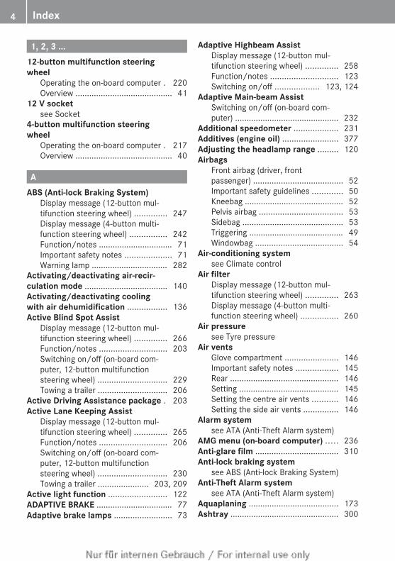
1, 2, 3 ...12-button multifunction steeringwheel
Operating the on-board computer . 220Overview .......................................... 41
12 V socketsee Socket
4-button multifunction steeringwheel
Operating the on-board computer . 217Overview .......................................... 40
AABS (Anti-lock Braking System)
Display message (12-button mul-tifunction steering wheel) .............. 247Display message (4-button multi-function steering wheel) ................ 242Function/notes ................................ 71Important safety notes .................... 71Warning lamp ................................. 282
Activating/deactivating air-recir-culation mode .................................... 140Activating/deactivating coolingwith air dehumidification ................. 136Active Blind Spot Assist
Display message (12-button mul-tifunction steering wheel) .............. 266Function/notes ............................. 203Switching on/off (on-board com-puter, 12-button multifunctionsteering wheel) .............................. 229Towing a trailer .............................. 206
Active Driving Assistance package . 203Active Lane Keeping Assist
Display message (12-button mul-tifunction steering wheel) .............. 265Function/notes ............................. 206Switching on/off (on-board com-puter, 12-button multifunctionsteering wheel) .............................. 230Towing a trailer ...................... 203, 209
Active light function ......................... 122ADAPTIVE BRAKE ................................. 77Adaptive brake lamps ......................... 73
Adaptive Highbeam AssistDisplay message (12-button mul-tifunction steering wheel) .............. 258Function/notes ............................. 123Switching on/off ................... 123, 124
Adaptive Main-beam AssistSwitching on/off (on-board com-puter) ............................................. 232
Additional speedometer ................... 231Additives (engine oil) ........................ 377Adjusting the headlamp range ......... 120Airbags
Front airbag (driver, frontpassenger) ....................................... 52Important safety guidelines ............. 50Kneebag ........................................... 52Pelvis airbag .................................... 53Sidebag ............................................ 53Triggering ......................................... 49Windowbag ...................................... 54
Air-conditioning systemsee Climate control
Air filterDisplay message (12-button mul-tifunction steering wheel) .............. 263Display message (4-button multi-function steering wheel) ................ 260
Air pressuresee Tyre pressure
Air ventsGlove compartment ....................... 146Important safety notes .................. 145Rear ............................................... 146Setting ........................................... 145Setting the centre air vents ........... 146Setting the side air vents ............... 146
Alarm systemsee ATA (Anti-Theft Alarm system)
AMG menu (on-board computer) ..... 236Anti-glare film .................................... 310Anti-lock braking system
see ABS (Anti-lock Braking System) Anti-Theft Alarm system
see ATA (Anti-Theft Alarm system) Aquaplaning ....................................... 173Ashtray ............................................... 300
4 Index
Assistance graphic (on-board com-puter, 12-button multifunctionsteering wheel) .................................. 228ASSYST PLUS
Displaying a service message ........ 312Hiding a service message .............. 312Notes ..................................... 312, 313Resetting the service interval dis-play ................................................ 313Service message ............................ 312Special service requirements ......... 313
ATA (anti-theft alarm system)Activating/deactivating ................... 79
ATA (Anti-Theft Alarm system)Function ........................................... 79Interior motion sensor ..................... 80Switching off the alarm .................... 79Tow-away protection ........................ 79
ATTENTION ASSISTActivating/deactivating ................. 229Display message (12-button mul-tifunction steering wheel) .............. 264Function/notes ............................. 198
Audio DVD (12-button multifunc-tion steering wheel) .......................... 225Audio menu (on-board computer,12-button multifunction steeringwheel) ................................................. 225Audio menu (on-board computer) .... 225Authorised workshop
see Qualified specialist workshop AUTO lights
Display message (12-button mul-tifunction steering wheel) .............. 257Display message (4-button multi-function steering wheel) ................ 255see Lights
Automatic engine start (ECO start/stop function) .................................... 154Automatic engine switch-off (ECOstart/stop function) .......................... 153Automatic headlamp mode .............. 119Automatic transmission
Accelerator pedal position ............. 160Automatic drive program ............... 161Changing gear ............................... 159Display message (4-button multi-function steering wheel) ................ 273
Driving tips .................................... 160Emergency running mode .............. 165Kickdown ....................................... 160Manual drive program .................... 163Overview ........................................ 158Problem (fault) ............................... 165Program selector button ................ 160Pulling away ................................... 152Releasing the parking lock man-ually ............................................... 165Selector lever ................................ 159Shift ranges ................................... 162Starting the engine ........................ 151Steering wheel gearshift paddles ... 161Trailer towing ................................. 160Transmission position display ........ 159Transmission positions .................. 159
Automatic transmission emer-gency running mode ......................... 165Automatic transmissions
Display message (12-button mul-tifunction steering wheel) .............. 275
Auxiliary heatingActivating/deactivating ................. 142Activating/deactivating (on thecentre console) .............................. 142Display message (12-button mul-tifunction steering wheel) .............. 277Important safety notes .................. 141Problem (display message) ............ 145Remote control .............................. 142Setting (on-board computer, 12-button multifunction steeringwheel) ............................................ 234Setting the departure time ............. 144
Auxiliary ventilationActivating/deactivating ................. 142Activating/deactivating (on thecentre console) .............................. 142Problem (display message) ............ 145Remote control .............................. 142
Axle load, permissible (trailer tow-ing) ...................................................... 382
Index 5
BBag hook ............................................ 297Ball coupling
Folding in ....................................... 212Folding out ..................................... 211
BAS (Brake Assist System) ................. 71BAS PLUS (Brake Assist SystemPLUS) .................................................... 71Battery (key)
Checking .......................................... 85Important safety notes .................... 85Replacing ......................................... 85
Battery (vehicle)Charging ........................................ 337Display message (12-button mul-tifunction steering wheel) .............. 262Display message (4-button multi-function steering wheel) ................ 259Important safety notes .................. 334Jump starting ................................. 338
Beltsee Seat belt
Belt force limiters (activation) ........... 49Belt tensioner
Activation ......................................... 49Function ........................................... 58
Blind Spot AssistActivating/deactivating ................. 229Display message (12-button mul-tifunction steering wheel) .............. 266Notes/function .............................. 200Trailer towing ................................. 201see Active Blind Spot Assist
BonnetActive bonnet (pedestrian protec-tion) ............................................... 314Closing ........................................... 315Display message (12-button mul-tifunction steering wheel) .............. 276Display message (4-button multi-function steering wheel) ................ 274Important safety notes .................. 313Opening ......................................... 315
BootEmergency release .......................... 94Important safety notes .................... 91Locking separately ........................... 93
Opening (automatically frominside) .............................................. 93Opening (automatically from out-side) ................................................. 92
Boot lidDisplay message (12-button mul-tifunction steering wheel) .............. 276Display message (4-button multi-function steering wheel) ................ 274Opening/closing .............................. 91Opening dimensions ...................... 380
Boot load (maximum) ........................ 380Brake Assist
see BAS (Brake Assist System) Brake fluid
Display message (12-button mul-tifunction steering wheel) .............. 249Display message (4-button multi-function steering wheel) ................ 244Notes ............................................. 378
Brake lampDisplay message (12-button mul-tifunction steering wheel) .............. 256Display message (4-button multi-function steering wheel) ................ 253
Brake lampsAdaptive ........................................... 73Changing bulbs .............................. 129
BrakesABS .................................................. 71BAS .................................................. 71BAS PLUS ........................................ 71Brake fluid (notes) ......................... 378Display message (12-button mul-tifunction steering wheel) .............. 247Display message (4-button multi-function steering wheel) ................ 242Driving tips .................................... 172High-performance brake system .... 173Important safety notes .................. 172Parking brake ................................ 170Warning lamp ................................. 282
Breakdownsee Flat tyre see Towing away/tow-starting
Bulbssee Replacing bulbs
6 Index
CCalling up a fault
see Display messages Car
see Vehicle Care
Automatic car wash ....................... 319Carpets .......................................... 325Display ........................................... 324Exterior lighting ............................. 322Gear or selector lever .................... 324High-pressure cleaner .................... 320Interior ........................................... 324Matt paintwork .............................. 321Notes ............................................. 319Paint .............................................. 321Plastic trim .................................... 324Reversing camera .......................... 323Roof lining ...................................... 325Seat belt ........................................ 325Seat cover ..................................... 324Sensors ......................................... 322Steering wheel ............................... 324Tail pipes ....................................... 323Trim pieces .................................... 324Washing by hand ........................... 320Wheels ........................................... 320Windows ........................................ 321Wiper blades .................................. 322Wooden trim .................................. 324
Car wash (care) ................................. 319CD player/CD changer (12-buttonmultifunction steering wheel) .......... 225Central locking
Automatic locking (on-board com-puter) ............................................. 234Locking/unlocking (key) .................. 83
Centre consoleLower section .................................. 43Upper section .................................. 42
Changing bulbsBrake lamps ................................... 129Cornering light function ................. 128Dipped-beam headlamps ............... 127Main-beam headlamps ................... 127Parking lamps (front) ..................... 127
Reversing lamps ............................ 129Standing lamps .............................. 127
Childrenchild seat lock .................................. 62In the vehicle ................................... 59Restraint systems ............................ 59
Child seatAutomatic recognition ..................... 62ISOFIX .............................................. 63On the front-passenger seat ............ 61Problem (malfunction) ..................... 70Recommendations ........................... 68Suitable positions ............................ 66Top Tether ....................................... 64
Child seat lock ..................................... 62Cigarette lighter ................................ 301Cleaning
Mirror turn signal ........................... 322Trailer tow hitch ............................. 323
Climate controlAuxiliary heating/ventilation .......... 141Controlling automatically ............... 137Convenience opening/closing(air-recirculation mode) ................. 140Cooling with air dehumidification . . 136Demisting the windows .................. 139Demisting the windscreen ............. 138Important safety notes .................. 134Indicator lamp ................................ 137Notes on using THERMATIC auto-matic climate control ..................... 135Overview of systems ...................... 134Problems with cooling with airdehumidification ............................ 137Problem with the rear windowheating .......................................... 140Setting the air distribution ............. 137Setting the airflow ......................... 138Setting the air vents ...................... 145Setting the temperature ................ 137Switching air-recirculation modeon/off ............................................ 140Switching on/off ........................... 136Switching the rear window heat-ing on/off ...................................... 139
Index 7
Switching the ZONE function on/off .................................................. 138THERMATIC automatic climatecontrol (2-zone) ............................. 135
ClockSetting (4-button multifunctionsteering wheel) .............................. 219
CockpitOverview .......................................... 32see Instrument cluster
COMAND Onlinesee separate operating instructions
Combination switch .......................... 121Constant headlamp mode
see Daytime driving lights Consumption statistics
On-board computer (12-buttonmultifunction steering wheel) ........ 222On-board computer (4-buttonmultifunction steering wheel) ........ 218
Convenience closing feature .............. 96Convenience opening/closing (air-recirculation mode) ........................... 140Convenience opening feature ............ 96Coolant (engine)
Checking the level ......................... 318Display message (12-button mul-tifunction steering wheel) .............. 261Display message (4-button multi-function steering wheel) ................ 258Important safety notes .................. 378Temperature display (12-buttonmultifunction steering wheel; AMG) 236Temperature gauge (12-buttonmultifunction steering wheel) ........ 219Temperature gauge (4-buttonmultifunction steering wheel) ........ 216Warning lamp ................................. 288
Coolingsee Climate control
Copyright ............................................. 29Cornering lamps
Changing bulbs .............................. 128
Cornering light functionDisplay message (12-button mul-tifunction steering wheel) .............. 255Display message (4-button multi-function steering wheel) ................ 252Function/notes ............................. 122
Coversee Roller sunblind
Crash-responsive emergency light-ing ....................................................... 125Cruise control
Cruise control lever ....................... 175Deactivating ................................... 176Display message (12-button mul-tifunction steering wheel) .............. 268Display message (4-button multi-function steering wheel) ................ 263Driving system ............................... 174Important safety notes .................. 174LIM indicator lamp ......................... 175Selecting ........................................ 175Setting a speed .............................. 176Storing and maintaining currentspeed ............................................. 175
Cup holderCentre console .............................. 299Important safety notes .................. 299Rear compartment ......................... 300
DData
see Technical data Date
Setting (4-button multifunctionsteering wheel) .............................. 219
Daytime driving lampsSwitching on/off (on-board com-puter, 12-button multifunctionsteering wheel) .............................. 231
Daytime driving lightsDisplay message (12-button mul-tifunction steering wheel) .............. 257Display message (4-button multi-function steering wheel) ................ 254
8 Index
Switching on/off (on-board com-puter, 4-button multifunctionsteering wheel) .............................. 218Switching on/off (switch) .............. 119
Declarations of conformity ................. 27Delayed switch-off
Exterior lighting (12-button multi-function steering wheel) ................ 232Interior lighting (12-button multi-function steering wheel) ................ 233
Diagnostics connection ...................... 27Diesel .................................................. 375Digital speedometer ......................... 223Dipped beam
Display message (4-button multi-function steering wheel) ................ 252
Dipped-beam headlampsChanging bulbs .............................. 127Display message (12-button mul-tifunction steering wheel) .............. 255Setting for driving abroad (sym-metrical) ........................................ 118Setting for driving on the right/left 232Switching on/off ........................... 119
Display (cleaning instructions) ........ 324Display message (12-button multi-function steering wheel)
ASSYST PLUS ................................ 312Calling up ....................................... 241Driving systems ............................. 264Engine ............................................ 261General notes ................................ 240Hiding ............................................ 240Key ................................................ 279KEYLESS-GO .................................. 279Lights ............................................. 255Safety systems .............................. 247Tyres .............................................. 271Vehicle ........................................... 275
Display message (4-button multi-function steering wheel)
ASSYST PLUS ................................ 312Calling up ....................................... 240Driving systems ............................. 263Engine ............................................ 258General notes ................................ 240Hiding ............................................ 240Key ................................................ 278
KEYLESS-GO .................................. 278Lights ............................................. 252Safety systems .............................. 242Tyres .............................................. 270Vehicle ........................................... 273
Distance recorder12-button multifunction steeringwheel ............................................. 222
Distance warning signal (warninglamp) .................................................. 290DISTRONIC PLUS
Activation conditions ..................... 181Deactivating ................................... 185Display message (12-button mul-tifunction steering wheel) .............. 267Displays in the multifunction dis-play ................................................ 185Driving tips .................................... 186Function/notes ............................. 179Important safety notes .................. 179Selecting ........................................ 181Setting the specified minimumdistance ......................................... 184Warning lamp ................................. 290
DoorAutomatic door locking feature(on-board computer, 12-buttonmultifunction steering wheel) ........ 234Automatic locking (switch) ............... 90Central locking/unlocking (key) ...... 83Control panel ................................... 45Display message (12-button mul-tifunction steering wheel) .............. 276Display message (4-button multi-function steering wheel) ................ 274Emergency locking ........................... 91Emergency unlocking ....................... 90Important safety notes .................... 88Opening (from the inside) ................ 89
Drive programAutomatic ...................................... 161Display ........................................... 159Manual ........................................... 163
Drive program selector ..................... 161Driver's door
see Door Drive system
Active Blind Spot Assist ................. 203
Index 9
Driving abroadService24h .................................... 313Symmetrical dipped beam ............. 118
Driving on flooded roads .................. 173Driving safety system
BAS PLUS (Brake Assist SystemPLUS) ............................................... 71Electronic Brake-force Distribution . . 76ESP® (Electronic Stability Pro-gram) ......................................... 73, 74ETS/4ETS (Electronic TractionSystem) ........................................... 73Important safety guidelines ............. 70
Driving safety systemsABS (Anti-lock Braking System) ....... 71ADAPTIVE BRAKE ............................. 77Adaptive brake lamps ...................... 73BAS (Brake Assist System) .............. 71Overview .......................................... 70PRE-SAFE® Brake ............................. 77
Driving systemActive Lane Keeping Assist ............ 206Display message (12-button mul-tifunction steering wheel) .............. 264Display message (4-button multi-function steering wheel) ................ 263
Driving systemsActive Driving Assistance package 203ATTENTION ASSIST ........................ 198Blind Spot Assist ............................ 200Cruise control ................................ 174Distronic Plus ................................ 179Dynamic handling package withsports mode .................................. 187HOLD function ............................... 188Lane Keeping Assist ...................... 202Lane package ................................ 200Parking Guidance ........................... 194PARKTRONIC ................................. 191RACE START (AMG vehicles) .......... 190Reversing camera .......................... 197Speed Limit Assist ......................... 198SPEEDTRONIC ............................... 177
Driving tipsAquaplaning ................................... 173Automatic transmission ................. 160Brakes ........................................... 172
DISTRONIC PLUS ........................... 186Downhill gradient ........................... 172Driving abroad ............................... 118Driving in winter ............................. 174Driving on flooded roads ................ 173Driving on wet roads ...................... 173General .......................................... 171Icy road surfaces ........................... 174Limited braking efficiency on sal-ted roads ....................................... 172New brake pads/linings ................ 173Running-in tips ............................... 148Snow chains .................................. 349Symmetrical dipped beam ............. 118Towing a trailer .............................. 209Wet road surface ........................... 172
Dynamic handling package withsports mode ....................................... 187
EEASY-ENTRY feature ......................... 107
Activating/deactivating (12-but-ton multifunction steering wheel) . . 235Function/notes ............................. 111
EASY-EXIT featureActivating/deactivating (12-but-ton multifunction steering wheel) . . 235Crash-responsive ........................... 112Function/notes ............................. 111
EBD (electronic brake force distri-bution)
Display message (12 button mul-tifunction steering wheel) .............. 248Function/notes ................................ 76
EBD (Electronic Brake-force Distri-bution)
Display message (4-button multi-function steering wheel) ................ 243
ECO displayFunction/notes ............................. 171On-board computer (12-buttonmultifunction steering wheel) ........ 223
ECO start/stop functionAutomatic engine start .................. 154Automatic engine switch-off .......... 153Deactivating/activating ................. 154General information ....................... 153
10 Index
Important safety notes .................. 153Introduction ................................... 153
Electrical fusessee Fuses
Electromagnetic compatibilityDeclaration of conformity ................ 27
Electronic brake force distribu-tion
see EBD (electronic brake forcedistribution)
Electronic Stability Programsee ESP® (Electronic Stability Program)
Emergency keyUnlocking the driver's door .............. 90
Emergency key elementFunction/notes ................................ 84Locking vehicle ................................ 91
Emergency releaseDriver's door .................................... 90
Emergency spare wheelGeneral notes ................................ 365Important safety notes .................. 365Storage location ............................ 366Technical data ............................... 367
Emergency unlockingBoot ................................................. 94Vehicle ............................................. 90
EngineECO start/stop function ................ 153Engine number ............................... 372Jump-starting ................................. 338Running irregularly ......................... 156Starting problems .......................... 156Starting the engine with the key .... 151Starting with KEYLESS GO ............. 151Stopping ........................................ 169Tow-starting (vehicle) ..................... 342Warning lamp (engine diagnostics) 288
Engine electronicsNotes ............................................. 370Problem (fault) ............................... 156
Engine jump startingsee Jump starting (engine)
Engine oilAdditives ........................................ 377Checking the oil level ..................... 316
Checking the oil level using thedipstick .......................................... 316Display message (12-button mul-tifunction steering wheel) .............. 262Display message (4-button multi-function steering wheel) ................ 260Filling capacity ............................... 377Notes about oil grades ................... 376Notes on oil level/consumption .... 316Temperature (12-button multi-function steering wheel) ................ 236Topping up ..................................... 317Viscosity ........................................ 377
Environmental protectionReturning an end-of-life vehicle ....... 25
ESP® (Electronic Stability Pro-gram)
AMG menu (on-board computer) . . . 237Deactivating/activating (AMGvehicles) .......................................... 75Deactivating/activating (exceptAMG vehicles) ................................ 228Deactivating/activating (notes;except AMG vehicles) ...................... 74Display message (12-button mul-tifunction steering wheel) .............. 247Display message (4-button multi-function steering wheel) ................ 242ETS/4ETS ........................................ 73Function/notes ......................... 73, 74Important safety guidelines ............. 73Trailer stabilisation .......................... 76Warning lamp ................................. 284
ETS/4ETS (Electronic Traction Sys-tem) ...................................................... 73Exhaust tail pipe (cleaning instruc-tions) .................................................. 323Exterior lighting
Settings options ............................. 118see Lights
Exterior mirrorsAdjusting ....................................... 112Anti-dazzle mode (automatic) ........ 114Folding in/out (automatically) ....... 113Folding in/out (electrically) ........... 113Folding in (12-button multifunc-tion steering wheel) ....................... 236Out of position (troubleshooting) ... 114
Index 11
Parking position ............................. 114Resetting ....................................... 113Storing settings (memory function) 115
FFault message
see Display messages Filler cap
see Fuel filler flap Fire extinguisher ............................... 329First-aid kit ......................................... 328Fitting a wheel
Removing a wheel .......................... 359Fitting wheels
Fitting a wheel ............................... 359Lowering the vehicle ...................... 360Preparing the vehicle ..................... 357Raising the vehicle ......................... 358Securing the vehicle against roll-ing away ........................................ 357
Flat tyreMOExtended run-flat system ......... 330Preparing the vehicle ..................... 330TIREFIT kit ...................................... 331see Emergency spare wheel
Floormat ............................................. 309Foglamps
Extended range .............................. 123Switching on/off ........................... 120
FrequenciesGarage door opener ....................... 306Mobile phone ................................. 370Two-way radio ................................ 370
Front foglampDisplay message (12-button mul-tifunction steering wheel) .............. 256
Front foglampsDisplay message (4-button multi-function steering wheel) ................ 253
FuelAdditives ........................................ 375Consumption information .............. 376Displaying the range (12-buttonmultifunction steering wheel) ........ 223Displaying the range (4-buttonmultifunction steering wheel) ........ 218E10 ................................................ 374
Grade (petrol) ................................ 374Important safety notes .................. 373Notes for AMG vehicles ................. 374Problem (malfunction) ................... 168Quality (diesel) ............................... 375Refuelling ....................................... 165Tank content/reserve fuel ............. 373Tank content display (12-buttonmultifunction steering wheel) .......... 37Tank content display (4-buttonmultifunction steering wheel) .......... 34
Fuel consumptionCurrent (12-button multifunctionsteering wheel) .............................. 223
Fuel filler flapOpening/closing ............................ 166
Fuel filterDisplay message (12-button mul-tifunction steering wheel) .............. 263Display message (4-button multi-function steering wheel) ................ 260
Fuel reserveDisplay message (12-button mul-tifunction steering wheel) .............. 263Display message (4-button multi-function steering wheel) ................ 260see Fuel
Fuel tankCapacity ........................................ 373Problem (malfunction) ................... 168
Fuse allocation chart (vehicle toolkit) ...................................................... 329Fuses
Allocation chart ............................. 343Before changing ............................. 343Fuse box in the boot ...................... 344Fuse box in the engine compart-ment .............................................. 343Important safety notes .................. 343
GGarage door opener
Clearing the memory ..................... 306Frequencies ................................... 306Important safety notes .................. 304
12 Index
Opening/closing the garage door .. 305Programming (button in the rear-view mirror) ................................... 304
Gear indicator (12-button multi-function steering wheel) .................. 236Gear or selector lever (cleaninginstructions) ...................................... 324Gearshift program
SETUP (on-board computer) .......... 237Genuine Mercedes-Benz parts ........... 25Glove compartment .......................... 295
HHandbrake
see Parking brake Hazard warning lamps ...................... 121Headlamp
Cleaning system (function) ............ 122Cleaning system (notes) ................ 379
HeadlampsMisting up ...................................... 124Topping up the cleaning system .... 318see Automatic headlamp mode
Head restraintsAdjusting ....................................... 106Adjusting (electrically) ................... 107Adjusting (manually) ...................... 107see NECK-PRO head restraints
Heatingsee Climate control
High-pressure cleaners .................... 320Hill start assist .................................. 152HOLD function
Deactivating ................................... 189Display message (12-button mul-tifunction steering wheel) .............. 265Display message (4-button multi-function steering wheel) ................ 263Function/notes ............................. 188
IIgnition lock
see Key positions Immobiliser .......................................... 78
Indicator and warning lampsCoolant .......................................... 288DISTRONIC PLUS ........................... 290Engine diagnostics ......................... 288Overview (12-button multifunc-tion steering wheel) ......................... 39Overview (4-button multifunctionsteering wheel) ................................ 36SPORT handling mode ................... 285
Indicator lampssee Warning and indicator lamps
Indicatorssee Turn signals
Insect protection on the radiator .... 315Instrument cluster (12-button mul-tifunction steering wheel)
Indicator and warning lamps ............ 39Overview .......................................... 37Settings ......................................... 230
Instrument cluster (4-button mul-tifunction steering wheel)
Indicator and warning lamps ............ 36Overview .......................................... 34
Instrument cluster lightingMultifunction steering wheel with12 buttons ..................................... 219Multifunction steering wheel with4 buttons ....................................... 216
Intelligent Light SystemActivating/deactivating (12-but-ton multifunction steering wheel) . . 232Display message (12-button mul-tifunction steering wheel) .............. 257Overview ........................................ 122Setting the dipped-beam head-lamps for driving on the right/left . 232
Interior lighting ................................. 125Automatic control system .............. 125Delayed switch-off (12-buttonmultifunction steering wheel) ........ 233Emergency lighting ........................ 125Manual control ............................... 125Overview ........................................ 125Reading lamp ................................. 125
Interior motion sensor ........................ 80ISOFIX child seat securing system .... 63
Index 13
JJack
Storage location ............................ 329Using ............................................. 358
Jump starting (engine) ...................... 338
KKey
Changing the battery ....................... 85Checking the battery ....................... 85Convenience closing feature ............ 96Convenience opening feature .......... 96Display message (4-button multi-function steering wheel) ................ 278Door central locking/unlocking ....... 83Emergency key element ................... 84Important safety notes .................... 82Loss ................................................. 87Modifying the programming ............. 84Positions (ignition lock) ................. 149Problem (malfunction) ..................... 87Starting the engine ........................ 151
KEYLESS-GOConvenience closing ........................ 96Display message (12-button mul-tifunction display) .......................... 279Display message (4-button multi-function display) ............................ 278Locking ............................................ 83Start/Stop button .......................... 149Starting the engine ........................ 151Unlocking ......................................... 83
Key positionsKey ................................................ 149KEYLESS GO .................................. 149
KeysDisplay message (12-button mul-tifunction steering wheel) .............. 279
KickdownDriving tips .................................... 160Manual drive program .................... 164
Kneebag ............................................... 52
LLamps
see Warning and indicator lamps Lane detection (automatic)
see Lane Keeping Assist Lane Keeping Assist
Activating/deactivating ................. 230Display message (12-button mul-tifunction steering wheel) .............. 265Function/information .................... 202
Lane package ..................................... 200Lap time (RACETIMER) ...................... 237Lashing eyelets ................................. 297Lights
Activating/deactivating the exte-rior lighting delayed switch-off(12-button multifunction steeringwheel) ............................................ 232Activating/deactivating the inte-rior lighting delayed switch-off(12-button multifunction steeringwheel) ............................................ 233Active light function ....................... 122Automatic headlamp mode ............ 119Cornering light function ................. 122Dipped-beam headlamps ............... 119Driving abroad ............................... 118Foglamps ....................................... 120Foglamps (extended range) ........... 123Hazard warning lamps ................... 121Headlamp flasher ........................... 121Headlamp range ............................ 120Light switch ................................... 118Main-beam headlamps ................... 121Motorway mode ............................. 123Parking lamps ................................ 120Rear foglamp ................................. 120Side lamps ..................................... 120Switching Adaptive HighbeamAssist on/off ................................. 232Switching the daytime drivinglights on/off (12-button multi-function steering wheel) ................ 231Switching the daytime drivinglights on/off (4-button multifunc-tion steering wheel) ....................... 218
14 Index
Switching the daytime drivinglights on/off (switch) ..................... 119Switching the surround lightingon/off (12-button multifunctionsteering wheel) .............................. 232Turn signals ................................... 121see Interior lighting see Replacing bulbs
Light sensorDisplay message (12-button mul-tifunction steering wheel) .............. 257Display message (4-button multi-function steering wheel) ................ 255
LIM indicator lampCruise control ................................ 175DISTRONIC PLUS ........................... 180Variable SPEEDTRONIC ................. 177
Limiting the speedsee SPEEDTRONIC
Loading guidelines ............................ 294Locking
see Central locking Locking (doors)
Automatic ........................................ 90Emergency locking ........................... 91From inside (central locking but-ton) .................................................. 89
Locking centrallysee Central locking
Locking verification signal (on-board computer) ............................... 234Lumbar support
Adjusting the 4-way lumbar sup-port ................................................ 108
Luxury multifunction steeringwheel
see On-board computer (12-but-ton multifunction steering wheel)
MM+S tyres ........................................... 348Main beam
Display message (4-button multi-function steering wheel) ................ 253
Main-beam headlampsChanging bulbs .............................. 127Display message (12-button mul-tifunction steering wheel) .............. 256Switching on/off ........................... 121
Maintenancesee ASSYST PLUS
Manual transmissionEngaging reverse gear ................... 158Gear lever ...................................... 157Pulling away ................................... 152Shifting to neutral .......................... 158Shift recommendation ................... 158Starting the engine ........................ 151
Matt finish (cleaning instructions) . . 321Memory card (audio) ......................... 225Memory function ............................... 115Mercedes-Benz Service Centre
see Qualified specialist workshop Message memory
12-button multifunction steeringwheel ............................................. 2414-button multifunction steeringwheel ............................................. 240
Messagessee Display messages
Mirrorsee Vanity mirror (in sun visor)
Mirrorssee Exterior mirrors see Rear-view mirror
Mobile phoneFrequencies ................................... 370Installation ..................................... 370Menu (on-board computer) ............ 226Notes/placing in the bracket ......... 302Transmission output (maximum) .... 370
Mobile telephonePre-installed bracket ...................... 303
Modifying the programming (key) ..... 84MOExtended run-flat system ........... 330Motorway mode ................................ 123MP3
Operating ....................................... 225see Separate operating instructions
Index 15
Multifunction display4-button multifunction steeringwheel ............................................. 217Permanent display (12-buttonmultifunction steering wheel) ........ 231
Multi-function display12-button multifunction steeringwheel ............................................. 221
Multifunction steering wheel (12buttons)
see On-board computer (12-but-ton multifunction steering wheel)
Multifunction steering wheel (4buttons)
see On-board computer (4-buttonmultifunction steering wheel)
NNavigation
Menu (on-board computer) ............ 224On-board computer (12-buttonmultifunction steering wheel) ........ 224see separate operating instructions
NECK-PRO head restraintsOperation ......................................... 55Resetting after being triggered ........ 55
Notes on running in a new vehicle . . 148
OOccupant safety
Children in the vehicle ..................... 59Important safety notes .................... 48
Odometer4-button multifunction steeringwheel ............................................. 218see Total distance recorder see Trip meter
Oilsee Engine oil
On-board computerRACETIMER ................................... 237
On-board computer (12-buttonmultifunction steering wheel)
AMG menu ..................................... 236Assist menu ................................... 227Audio menu ................................... 225
Convenience submenu .................. 235DISTRONIC PLUS ........................... 185Important safety notes .................. 216Instrument cluster submenu .......... 230Lights submenu ............................. 231Menu overview .............................. 222Navigation menu ............................ 224Operating ....................................... 220Operating the video DVD ............... 226Range ............................................ 223Service menu ................................. 230Standard display submenu ............ 222Telephone menu ............................ 226Trip menu ...................................... 222
On-board computer (12-buttonmultifunction steering wheel)
Displaying service messages ......... 312Display messages .......................... 240Heating submenu ........................... 234Message memory .......................... 241Vehicle submenu ........................... 233
On-board computer (12-buttonmultifunction steering wheel)Set-tings menu ......................................... 230On-board computer (12-buttonmultifunction steering wheel) sub-menu
Factory setting ............................... 236On-board computer (4-button mul-tifunction steering wheel)
Important safety notes .................. 216Menu overview .............................. 218Switching daytime driving lightson/off ............................................ 218
On-board computer (4-button mul-tifunction steering wheel)
Displaying service messages ......... 312Display messages .......................... 240Individual vehicle settings .............. 217Message memory .......................... 240Operating ....................................... 217Range ............................................ 218Standard display ............................ 218Time/date ..................................... 219Trip computer ................................ 218
Opening and closing the side trimpanels ................................................. 128
16 Index
Operating instructionsVehicle equipment ........................... 26
Operating safetyDeclaration of conformity ................ 27Important safety note ...................... 26
Operating systemsee On-board computer
Outside temperatureDisplay (12-button multifunctionsteering wheel) .............................. 220Display (4-button multifunctionsteering wheel) .............................. 217
Overhead control panel ...................... 44
PPaint code .......................................... 372Paintwork (cleaning instructions) . . . 321Panic alarm .......................................... 48Panorama sliding sunroof
Important safety information ........... 98Opening/closing .............................. 99Opening/closing the roller sun-blind ............................................... 100Problem (malfunction) ................... 100Rain closing feature ......................... 99Resetting ....................................... 100
Park AssistParking Guidance ........................... 194
Parking ............................................... 169Important safety notes .................. 169Parking brake ................................ 170Position of exterior mirror, front-passenger side ............................... 114Reversing camera .......................... 197see PARKTRONIC
Parking aidsee Exterior mirrors see PARKTRONIC
Parking assistancesee PARKTRONIC
Parking brake .................................... 170Display message (12-button mul-tifunction steering wheel) .............. 248Display message (4-button multi-function steering wheel) ................ 243Notes/function .............................. 170
Parking GuidanceDisplay message (12-button mul-tifunction steering wheel) .............. 266Important safety notes .................. 194Trailer towing ................................. 196
Parking lampDisplay message (12-button mul-tifunction steering wheel) .............. 257Display message (4-button multi-function steering wheel) ................ 254
Parking lampsChanging bulbs .............................. 127Switching on/off ........................... 120
PARKTRONICDeactivating/activating ................. 193Driving system ............................... 191Function/notes ............................. 191Important safety notes .................. 191Problem (fault) ............................... 194Sensor range ................................. 191Trailer towing ................................. 193Warning display ............................. 192
PASS AIRBAG OFFsee PASSENGER AIRBAG OFF
PASSENGER AIRBAG OFFIndicator lamp .................................. 62Problem (malfunction) ..................... 70
Petrol .................................................. 374Plastic trim (cleaning instructions) . 324Power windows
see Side windows PRE-SAFE® (preventative occupantprotection)
Display message (12-button mul-tifunction steering wheel) .............. 249Display message (4-button multi-function steering wheel) ................ 244
PRE-SAFE® (preventive occupantsafety system)
Operation ......................................... 54PRE-SAFE® Brake
Activating/deactivating ................. 229Display message (12-button mul-tifunction steering wheel) .............. 250Function/notes ................................ 77Warning lamp ................................. 290
Program selector button .................. 160
Index 17
Protection of the environmentGeneral notes .................................. 25
Pulling awayAutomatic transmission ................. 152Manual transmission ...................... 152
QQualified specialist workshop ........... 28
RRACE START (AMG vehicles) ............. 190RACETIMER (on-board computer) .... 237Radar sensor system
Activating/deactivating ................. 234Display message (12-button mul-tifunction steering wheel) .............. 265
Radiator cover ................................... 315Radio
Selecting a station (12-buttonmultifunction steering wheel) ........ 225see separate operating instructions
Radio-based vehicle componentsDeclaration of conformity ................ 27
Rain closing feature (panoramasliding sunroof) ................................... 99Range (fuel)
Displaying (12-button multifunc-tion steering wheel) ....................... 223Displaying (4-button multifunc-tion steering wheel) ....................... 218
Reading lamp ..................................... 125Rear compartment
Setting the air vents ...................... 146Rear-compartment seat belt sta-tus indicator ........................................ 58Rear foglamp
Display message (12-button mul-tifunction steering wheel) .............. 256Display message (4-button multi-function steering wheel) ................ 254Switching on/off ........................... 120
Rear seat (folding the backrest for-wards/back) ...................................... 296Rear-view mirror
Anti-dazzle mode (automatic) ........ 114Dipping (manual) ........................... 112
Rear window heatingProblem (fault) ............................... 140Switching on/off ........................... 139
RefuellingFuel gauge ....................................... 34Important safety notes .................. 165Notes for AMG vehicles ................. 374Refuelling process ......................... 166see Fuel
Releasing the parking lock man-ually (automatic transmission) ........ 165Remote control
Auxiliary heating/ventilation .......... 142Changing the batteries (auxiliaryheating) ......................................... 144Garage door opener ....................... 304Programming (garage door opener) 304
Replacing bulbsImportant safety notes .................. 125Overview of bulb types .................. 126
Replacing the battery (auxiliaryheating remote control) .................... 144Reserve (fuel tank)
see Fuel Reserve fuel
Display message (12-button mul-tifunction steering wheel) .............. 263Display message (4-button multi-function steering wheel) ................ 260Warning lamp ................................. 288
Restraint systemsee SRS (Supplemental RestraintSystem)
Rev counter12-button multifunction steeringwheel ............................................. 2194-button multifunction steeringwheel ............................................. 217
Reverse gearEngaging (automatic transmission) 159Engaging (manual transmission) .... 158
Reversing cameraCleaning instructions ..................... 323Function/notes ............................. 197
Reversing featurePanorama sliding sunroof ................ 98Side windows ................................... 95
18 Index
Reversing functionBoot lid ............................................ 91Roller sunblind ................................. 99
Reversing lampChanging bulbs .............................. 129Display message (12-button mul-tifunction steering wheel) .............. 257Display message (4-button multi-function steering wheel) ................ 254
Roller blindsee Roller sunblind
Roller sunblindOpening/closing ............................ 100Panorama sliding sunroof ................ 99
Roof carrier ........................................ 298Roof lining and carpets (cleaninginstructions) ...................................... 325Roof load (maximum) ........................ 380Route (navigation)
see Route guidance (navigation) Route guidance (navigation) ............ 224
SSafety
Children in the vehicle ..................... 59Child restraint systems .................... 59
Safety systemsee Driving safety system
SeatSeat backrest display message(12-button multifunction steeringwheel) ............................................ 276Seat backrest display message (4-button multifunction steeringwheel) ............................................ 274
Seat beltActivating/deactivating seat-beltadjustment (12-button multifunc-tion steering wheel) ....................... 236Adjusting the driver's and front-passenger seat belt ......................... 57Belt force limiter .............................. 58Belt tensioner .................................. 58Cleaning ......................................... 325Display message (12-button mul-tifunction steering wheel) .............. 250
Display message (4-button multi-function steering wheel) ................ 245Fastening ......................................... 57Important safety guidelines ............. 56Rear seat belt status indicator ......... 58Releasing ......................................... 58Warning lamp ................................. 281Warning lamp (function) ................... 58
SeatsAdjusting (electrically) ................... 106Adjusting (manually and electri-cally) .............................................. 106Adjusting the 4-way lumbar sup-port ................................................ 108Adjusting the head restraint .......... 106Cleaning the cover ......................... 324Correct driver's seat position ........ 104Folding the backrests forward/back ............................................... 107Important safety notes .................. 105Seat heating problem .................... 110Seat ventilation problem ................ 110Storing settings (memory function) 115Switching seat heating on/off ....... 108Switching the seat ventilation on/off .................................................. 110
Sensors (cleaning instructions) ....... 322Service
see ASSYST PLUS Service menu (12-button multi-function steering wheel) .................. 230Service products
Brake fluid ..................................... 378Coolant (engine) ............................ 378Engine oil ....................................... 376Fuel ................................................ 372Important safety notes .................. 372Washer fluid ................................... 379
SettingsFactory (12-button multifunctionsteering wheel) .............................. 236On-board computer (12-buttonmultifunction steering wheel) ........ 230
Setting the air distribution ............... 137Setting the airflow ............................ 138SETUP (on-board computer) ............. 237Shifting to neutral (manual trans-mission) ............................................. 158
Index 19
Sidebag ................................................ 53Side lamps
Changing bulbs .............................. 127Switching on/off ........................... 120
Side marker lampDisplay message (12-button mul-tifunction steering wheel) .............. 257Display message (4-button multi-function steering wheel) ................ 254
Side windowsConvenience closing ........................ 96Convenience opening ...................... 96Important safety notes .................... 94Opening/closing .............................. 95Problem (malfunction) ..................... 97resetting .......................................... 97
Sliding sunroofsee Panorama sliding sunroof
Snow chains ...................................... 349Socket
Centre console .............................. 302Rear compartment ......................... 302
SocketsGeneral notes ................................ 302
Spare wheelStorage location ............................ 366
Specialist workshop ............................ 28Speed, controlling
see Cruise control Speed Limit Assist
Activating/deactivating the warn-ing function .................................... 228Displaying ...................................... 228Display message (12-button mul-tifunction steering wheel) .............. 264Display message in the multifunc-tion display .................................... 199Important safety notes .................. 199
SpeedometerActivating/deactivating the addi-tional speedometer ........................ 231Digital ............................................ 223In the instrument cluster (12-but-ton multifunction steering wheel) .... 37In the instrument cluster (4-but-ton multifunction steering wheel) .... 34
Segments ...................................... 220Selecting the unit of measurement 230see Instrument cluster
SPEEDTRONICDeactivating variable ..................... 178Display message (12-button mul-tifunction steering wheel) .............. 268Display message (4-button multi-function steering wheel) ................ 263Function/notes ............................. 177Important safety notes .................. 177LIM indicator lamp ......................... 177Permanent ..................................... 179Selecting ........................................ 178Storing the current speed .............. 178Variable ......................................... 177
SPORT handling modeActivating/deactivating (AMGvehicles) .......................................... 75Warning lamp ................................. 285
SRS (Supplemental Restraint Sys-tem)
Display message (12-button mul-tifunction steering wheel) .............. 251Display message (4-button multi-function steering wheel) ................ 245Introduction ..................................... 49Warning lamp ................................. 287Warning lamp (function) ................... 49
Start/stop functionsee ECO start/stop function
Starting (engine) ................................ 150Steering
Display message (12-button mul-tifunction steering wheel) .............. 277Display message (4-button multi-function steering wheel) ................ 275
Steering wheelAdjusting (electrically) ................... 111Adjusting (manually) ...................... 111Buttons (12-button multifunctionsteering wheel) .............................. 220Buttons (4-button multifunctionsteering wheel) .............................. 217Cleaning ......................................... 324Gearshift paddles ........................... 161Important safety notes .................. 110Storing settings (memory function) 115
20 Index
Steering wheel gearshift paddles .... 161Stopwatch (RACETIMER) ................... 237Stowage areas ................................... 294Stowage compartments
Armrest (under) ............................. 295Centre console .............................. 295Cup holder ..................................... 299Glove compartment ....................... 295Important safety information ......... 294
Stowage net ....................................... 296Stowage space
Stowage net ................................... 296Stowage well beneath the bootfloor .................................................... 298Summer opening
see Convenience opening feature Summer tyres .................................... 348Sun visor ............................................ 300Supplemental Restraint System
see SRS (Supplemental RestraintSystem)
Surround lighting (12-button mul-tifunction steering wheel) ................ 232Switching off the alarm (ATA) ............ 79
TTail lamp
Display message (12-button mul-tifunction steering wheel) .............. 256Display message (4-button multi-function steering wheel) ................ 253
Tanksee Fuel tank
Tank contentDisplaying the range (12-buttonmultifunction steering wheel) ........ 223Displaying the range (4-buttonmultifunction steering wheel) ........ 218Fuel gauge (12-button multifunc-tion steering wheel) ......................... 37Fuel gauge (4-button multifunc-tion steering wheel) ......................... 34
Technical dataCapacities ...................................... 372Emergency spare wheel ................. 367Information .................................... 370Trailer loads ................................... 382
Tyres/wheels ................................. 361Vehicle data ................................... 380
TelephoneAccepting a call ............................. 226Display message (12-button mul-tifunction steering wheel) .............. 278Menu (on-board computer) ............ 226Number from the phone book ........ 227Redialling ....................................... 227Rejecting/ending a call ................. 227Telephone compartment ................ 295
TemperatureCoolant (12-button multifunctionsteering wheel; AMG) ..................... 236Coolant (12-button multifunctionsteering wheel) .............................. 219Coolant (4-button multifunctionsteering wheel) .............................. 216Engine oil (12-button multifunc-tion steering wheel) ....................... 236Outside temperature (12-buttonmultifunction steering wheel) ........ 220Outside temperature (4-buttonmultifunction steering wheel) ........ 217Setting (climate control) ................ 137
TEMPOMATFunction/notes ............................. 174
Theft-deterrent systemATA (Anti-Theft Alarm system) ......... 79Immobiliser ...................................... 78
Through-loading feature ................... 296Time
Setting the clock (4-button multi-function steering wheel) ................ 219see Separate Owner's manual
Timing (RACETIMER) ......................... 237TIREFIT kit .......................................... 331Top Tether ............................................ 64Total distance recorder
Displaying (12-button multifunc-tion steering wheel) ....................... 222Displaying (4-button multifunc-tion steering wheel) ....................... 218
Tow-away protection .......................... 79Towing
Important safety notes .................. 340With the rear axle raised ................ 341
Index 21
Towing a trailerActive Blind Spot Assist ................. 206Active Lane Keeping Assist .... 203, 209Axle load, permissible .................... 382Bulb failure indicator for LED lamps 213Lights display message (12-but-ton multifunction steering wheel) . . 255Lights display message (4-buttonmultifunction steering wheel) ........ 252Trailer tow hitch display message(12-button multifunction steeringwheel) ............................................ 277Trailer tow hitch display message(4-button multifunction steeringwheel) ............................................ 275
Towing awayFitting the towing eye .................... 341Removing the towing eye ............... 341With both axles on the ground ....... 342
Tow-startingEmergency engine starting ............ 342Fitting the towing eye .................... 341Important safety notes .................. 340Removing the towing eye ............... 341
Trailer couplingsee Towing a trailer
Trailer towing7-pin connector ............................. 214Blind Spot Assist ............................ 201Cleaning the trailer tow hitch ......... 323Coupling up a trailer ...................... 212Decoupling a trailer ....................... 212Driving tips .................................... 209Folding in the ball coupling ............ 212Folding out the ball coupling .......... 211Important safety notes .................. 209Mounting dimensions .................... 381Parking Guidance ........................... 196Parktronic ...................................... 193Power supply ................................. 213Shift range ..................................... 160Trailer loads ................................... 382
Transmissionsee Automatic transmission see Manual transmission
Transporting the vehicle .................. 342Trim pieces (cleaning instructions) . 324
Trip computerOn-board computer (12-buttonmultifunction steering wheel) ........ 222On-board computer (4-buttonmultifunction steering wheel) ........ 218
Trip meterDisplaying/resetting (4-buttonmultifunction steering wheel) ........ 218Displaying (12-button multifunc-tion steering wheel) ....................... 222Resetting (12-button multifunc-tion steering wheel) ....................... 223
Turn signalDisplay message (12-button mul-tifunction steering wheel) .............. 256Display message (4-button multi-function steering wheel) ................ 253
Turn signalsSwitching on/off ........................... 121
Two-way radioFrequencies ................................... 370Installation ..................................... 370Transmission output (maximum) .... 370
Type identification platesee Vehicle identification plate
Tyre pressureCalling up (on-board computer) ..... 353Display message (12-button mul-tifunction steering wheel) .............. 271Display message (4-button multi-function steering wheel) ................ 270Important safety notes .................. 353Not reached (TIREFIT) .................... 333Pressure loss warning .................... 351Reached (TIREFIT) .......................... 333Recommended ............................... 350
Tyre pressure loss warningGeneral notes ................................ 351Important safety notes .................. 351Restarting ...................................... 352
Tyre pressure monitorChecking the tyre pressure elec-tronically ........................................ 354Function/notes ............................. 353General notes ................................ 353Important safety notes .................. 353Restarting ...................................... 355
22 Index
Warning lamp ................................. 291Warning message .......................... 354
TyresChanging a wheel .......................... 356Checking ........................................ 347Direction of rotation ...................... 356Display message (12-button mul-tifunction steering wheel) .............. 271Display message (4-button multi-function steering wheel) ................ 270Important safety notes .................. 346M+S tyres ...................................... 348MOExtended tyres ......................... 330Replacing ....................................... 356Service life ..................................... 348Storing ........................................... 356Summer tyres ................................ 348Tyre size (data) .............................. 361Tyre tread ...................................... 347see Flat tyre
UUnlocking
Emergency unlocking ....................... 90From inside the vehicle (centralunlocking button) ............................. 89
VVanity mirror (in sun visor) .............. 300Variable SPEEDTRONIC
see SPEEDTRONIC Vehicle
Correct use ...................................... 28Data acquisition ............................... 28Electronics ..................................... 370Emergency locking ........................... 91Emergency unlocking ....................... 90Equipment ....................................... 26Implied warranty .............................. 28Individual settings .......................... 230Leaving parked up ......................... 170Locking (in an emergency) ............... 91Locking (key) ................................... 83Lowering ........................................ 360Pulling away ................................... 152Raising ........................................... 358Registration ..................................... 28
Securing from rolling away ............ 357Towing away .................................. 340Tow-starting ................................... 340Transporting .................................. 342Unlocking (in an emergency) ........... 90Unlocking (key) ................................ 83Vehicle data ................................... 380
Vehicle data ....................................... 380Vehicle dimensions ........................... 380Vehicle emergency locking ................ 91Vehicle identification number
see VIN Vehicle identification plate .............. 372Vehicle tool kit .................................. 329Video (DVD) ........................................ 226Video DVD (12-button multifunc-tion steering wheel) .......................... 226VIN ...................................................... 372
WWarning and indicator lamps
ABS ................................................ 282Brakes ........................................... 282Distance warning signal ................. 290ESP® .............................................. 284ESP® OFF ....................................... 285Fuel tank ........................................ 288LIM (cruise control) ........................ 175LIM (DISTRONIC PLUS) .................. 180LIM (variable SPEEDTRONIC) ......... 177PASSENGER AIRBAG OFF ................ 62Reserve fuel ................................... 288Seat belt ........................................ 281SRS ................................................ 287Tyre pressure monitor ................... 291
Warning triangle ................................ 328Washer fluid
Display message (12-button mul-tifunction steering wheel) .............. 278Display message (4-button multi-function steering wheel) ................ 275
Wheel bolt tightening torque ........... 360Wheel chock ...................................... 357Wheels
Changing/replacing ....................... 356Changing a wheel .......................... 356Checking ........................................ 347
Index 23
Cleaning ......................................... 320Cleaning (warning) ......................... 356Emergency spare wheel ................. 365Fitting a new wheel ........................ 359Fitting a wheel ............................... 357Important safety notes .................. 346Removing a wheel .......................... 359Storing ........................................... 356Tightening torque ........................... 360Wheel size/tyre size ...................... 361
WindowbagDisplay message (12-button mul-tifunction steering wheel) .............. 252Display message (4-button multi-function steering wheel) ................ 246Operation ......................................... 54
WindowsCleaning ......................................... 321see Side windows
WindscreenDemisting ...................................... 138see Windscreen
Windscreen washer fluidsee Windscreen washer system
Windscreen washer system ............. 318Notes ............................................. 379
Windscreen wipersProblem (malfunction) ................... 132Replacing the wiper blades ............ 130Switching on/off ........................... 129
Winter operationImportant safety notes .................. 348Radiator cover ............................... 315Slippery road surfaces ................... 174Snow chains .................................. 349
Winter tyresLimiting the speed (on-board com-puter) ............................................. 233M+S tyres ...................................... 348
Wiper bladesCleaning ......................................... 322Important safety notes .................. 130Replacing ....................................... 130
Wooden trim (cleaning instructions) 324Workshop
see Qualified specialist workshop
ZZONE function
Switching on/off ........................... 138
24 Index
Protection of the environment
General notes
H Environmental noteDaimler's declared policy is one of compre-hensive environmental protection.Our objectives are to use the natural resour-ces which form the basis of our existence onthis planet sparingly and in a manner whichtakes the requirements of both nature andhumanity into consideration.You too can help to protect the environmentby operating your vehicle in an environmen-tally-responsible manner.Fuel consumption and the rate of engine,transmission, brake and tyre wear depend onthe following factors:Roperating conditions of your vehicleRyour personal driving styleYou can influence both factors. Therefore,please bear the following in mind:Operating conditions:Ravoid short trips, as these increase fuel
consumption.Robserve the correct tyre pressure.Rdo not carry any unnecessary weight in the
vehicle.Rremove the roof rack once you no longer
need it.Ra regularly serviced vehicle will contribute
to environmental protection. You shouldtherefore adhere to the service intervals.Rall maintenance work should be carried out
at a qualified specialist workshop.Personal driving style:Rdo not depress the accelerator pedal when
starting the engine.Rdo not warm up the engine when the vehicle
is stationary.Rdrive carefully and maintain a safe distance
from the vehicle in front.Ravoid frequent, sudden acceleration and
braking.
Rchange gear in good time and use each gearonly up to Ô of its maximum engine speed.Rswitch off the engine in stationary traffic.Rmonitor the vehicle's fuel consumption.
Returning an end-of-life vehicleEU countries only:Mercedes-Benz will take back your old vehicleto dispose of it in an environmentally-respon-sible manner in accordance with the Euro-pean Union (EU) End of Life Vehicles Direc-tive.There is a network of return points and dis-assembly plants available. You can returnyour vehicle to these plants free of charge.This makes a valuable contribution to therecycling process and the conservation ofresources.For further information on recycling old vehi-cles, recovery and the terms of the policy,visit the Mercedes-Benz homepage.
Genuine Mercedes-Benz parts
H Environmental noteDaimler AG also supplies reconditionedassemblies and parts which are of the samequality as new parts. For these, the same war-ranty applies as for new parts.
! Airbags and seat belt tensioners, as wellas control units and sensors for theserestraint systems, may be installed in thefollowing areas of your vehicle:RdoorsRdoor pillarsRdoor sillsRseatsRdashboardRinstrument clusterRcentre console
Introduction 25
Z
Do not install accessories such as audiosystems in these areas. Do not carry outrepairs or welding. You could impair theoperating efficiency of the restraint sys-tems.Have accessories retrofitted at a qualifiedspecialist workshop.
You could jeopardise the operating safety ofyour vehicle if you use parts, tyres and wheelsas well as accessories relevant to safetywhich have not been approved by Mercedes.This could lead to malfunctions in safety-rel-evant systems, e.g. the brake system. Useonly genuine Mercedes-Benz parts or parts ofequal quality. Only use tyres, wheels andaccessories that have been specificallyapproved for your vehicle.Mercedes-Benz tests genuine parts and con-version parts and accessories that have beenspecifically approved for your vehicle for theirreliability, safety and suitability. Despiteongoing market research, Mercedes-Benz isunable to assess other parts. Mercedes-Benztherefore accepts no responsibility for theuse of such parts in Mercedes-Benz vehicles,even if they have been officially approved orindependently approved by a testing centre.In Germany, certain parts are only officiallyapproved for installation or modification ifthey comply with legal requirements. Thisalso applies to some other countries. All gen-uine Mercedes-Benz parts meet the approvalrequirements. The use of non-approved partsmay invalidate the vehicle's general operatingpermit.This is the case:Rif they cause a change of the vehicle type
from that for which the vehicle's generaloperating permit was grantedRif other road users could be endangeredRif the emission or noise levels are adversely
affectedAlways specify the vehicle identification num-ber (VIN) (Y page 372) when ordering genu-ine Mercedes-Benz parts.
Owner's Manual
Vehicle equipmentThis Owner's Manual describes all modelsand all standard and optional equipmentavailable for your vehicle at the time of pub-lication of the Owner's Manual. Country-spe-cific differences are possible. Note that yourvehicle may not be fitted with all featuresdescribed. This is also the case for systemsand functions relevant to safety. Therefore,the equipment on your vehicle may differ fromthat in the descriptions and illustrations.The original purchase contract documenta-tion for your vehicle contains a list of all of thesystems in your vehicle.Should you have any questions concerningequipment and operation, please consult aMercedes-Benz Service Centre.The Owner's Manual and Service Booklet areimportant documents and should kept in thevehicle.
Operating safety
Important safety notes
G WARNINGIf you do not have the prescribed service/maintenance work or necessary repairs car-ried out, this could result in malfunctions orsystem failures. There is a risk of an accident.Always have the prescribed service/mainte-nance work as well as necessary repairs car-ried out at a qualified specialist workshop.
G WARNINGIf you switch off the ignition while driving,safety-relevant functions are only availablewith limitations, or not at all. This could affect,for example, the power steering and the brakeboosting effect. You will require considerablymore effort to steer and brake. There is a riskof an accident.Do not switch off the ignition while driving.
26 Introduction
G WARNINGModifications to electronic components, theirsoftware as well as wiring could effect theirfunction and/or the operation of other net-worked components. This could in particularalso be the case for systems relevant tosafety. They might not function properly anymore and/or jeopardise the operationalsafety of the vehicle. There is an increasedrisk of an accident and injury.Do not attempt to modify the wiring as well aselectronic components or their software.Always have work on electrical and electroniccomponents carried out at a qualified special-ist workshop.
! There is a risk of damage to the vehicle if:Rthe vehicle makes contact with the
ground, e.g. on a high kerb or a looseroad surfaceRyou drive too quickly over an obstacle,
e.g. a kerb or a potholeRa heavy object hits the underbody or
chassis componentIn these or similar situations, the vehiclebody, the underbody, chassis components,wheels or tyres could be damaged even ifthis is not visible. Components that havebeen damaged in this way can unexpect-edly fail or no longer be able to assimilatethe loads occurring in the event of an acci-dent.If the underbody panelling is damaged,flammable material, such as leaves, grassor twigs, could collect between the under-body and underbody panelling. Thesematerials could ignite if they remain in con-tact with hot components of the exhaustsystem for an extended period.Have the vehicle checked and repairedimmediately at a qualified specialist work-shop. If you become aware when continu-ing the journey that driving safety has beeneffected, stop as soon as possible inaccordance with the traffic conditions. In
such cases, consult a qualified specialistworkshop.
Declarations of conformity
Wireless vehicle componentsThe following information applies to all com-ponents of the vehicle and the informationsystems and communication devices integra-ted into the vehicle which receive and/ortransmit radio waves:The components of this vehicle that receiveand/or transmit radio waves are compliantwith the basic requirements and all other rel-evant conditions of Directive 1999/5/EC.You can obtain further information from anyMercedes-Benz Service Centre.
Electromagnetic compatibilityThe electromagnetic compatibility of the vehi-cle components has been checked and certi-fied according to the currently valid versionof Regulation ECE-R 10.
Diagnostics connectionThe diagnostics connection is only intendedfor the connection of diagnostic equipment ata qualified specialist workshop.
G WARNINGIf you connect equipment to a diagnosticsconnection in the vehicle, it can affect theoperation of the vehicle systems. This mayaffect the operating safety of the vehicle.There is a risk of an accident.Do not connect any equipment to a diagnos-tics connection in the vehicle.
G WARNINGObjects in the driver's footwell may restrictthe clearance around the pedals or block adepressed pedal. This jeopardises the oper-ating and road safety of the vehicle. There isa risk of an accident.
Introduction 27
Z
Stow all objects securely in the vehicle so thatthey do not get into the driver's footwell.Always fit the floormats securely and as pre-scribed in order to ensure that there is alwayssufficient room for the pedals. Do not useloose floormats and do not place several floor-mats on top of one another.
! If the engine is switched off and equip-ment on the diagnostics connection isused, the starter battery may discharge.
Connecting equipment to the diagnosticsconnection can lead to emissions monitoringinformation being reset, for example. Thismay lead to the vehicle failing to meet therequirements of the next emissions test dur-ing the main inspection.
Qualified specialist workshopA qualified specialist workshop has the nec-essary special skills, tools and qualificationsto correctly carry out any necessary work onyour vehicle. This particularly applies to workrelevant to safety.Observe the notes in the Service Booklet.Always have the following work carried out ata qualified specialist workshop:Rwork relevant to safetyRservice and maintenance workRrepair workRmodifications, installations and conver-
sionsRwork on electronic componentsMercedes-Benz recommends that you use aMercedes-Benz Service Centre.
Vehicle registrationMercedes-Benz may ask its Service Centresto carry out technical inspections on certainvehicles. The quality or safety of the vehicleis improved as a result of the inspection.Mercedes-Benz can only inform you aboutvehicle checks if it has your registration data.
It is possible that your vehicle has not yetbeen registered in your name in the followingcases:Rif your vehicle was not purchased at an
authorised specialist dealer.Rif your vehicle has not yet been examined
at a Mercedes-Benz Service Centre.It is advisable to register your vehicle with aMercedes-Benz Service Centre.Inform Mercedes-Benz as soon as possibleabout any change in address or vehicle own-ership. You can do this at a Mercedes-BenzService Centre, for example.
Correct useIf you remove any warning stickers, you orothers could fail to recognise certain dangers.Leave warning stickers in position.Observe the following information when driv-ing your vehicle:Rthe safety notes in this manualRthe technical data in this manualRtraffic rules and regulationsRlaws and safety standards pertaining to
motor vehicles
Implied warranty! Follow the instructions in this manual
about the proper operation of your vehicleas well as about possible vehicle damage.Damage to your vehicle that arises fromculpable contraventions against theseinstructions are not covered either byMercedes-Benz implied warranty or by theNew or Used-Vehicle Warranty.
Data stored in the vehicle
A wide range of electronic components inyour vehicle contain data memories.
28 Introduction
These data memories temporarily or perma-nently store technical information about:Rthe vehicle's operating stateReventsRfaultsIn general, this technical information docu-ments the state of a component, a module, asystem or the surroundings.These include, for example:Roperating conditions of system compo-
nents, e.g. fluid levelsRthe vehicle's status messages and those of
its individual components, e.g. number ofwheel revolutions/speed, deceleration inmovement, lateral acceleration, accelera-tor pedal positionRmalfunctions and defects in important sys-
tem components, e.g. lights, brakesRvehicle reactions and operating conditions
in special driving situations, e.g. airbagdeployment, intervention of stability con-trol systemsRambient conditions, e.g. outside tempera-
tureThis data is of an exclusively technical natureand can be used to:Rassist in recognising and rectifying faults
and defectsRanalyse vehicle functions, e.g. after an acci-
dentRoptimise vehicle functionsThe data cannot be used to trace the vehicle'smovements.When your vehicle is serviced, technical infor-mation can be read from the event data mem-ory and fault data memory.Services include, for example:Rrepair servicesRservice processesRwarrantiesRquality assuranceIt is read by employees of the service network(including manufacturers) using special diag-
nostic testers. More detailed information isobtained from it, if required.After a fault has been rectified, the informa-tion is deleted from the fault memory or iscontinually overwritten.When operating the vehicle, situations areconceivable in which this technical data, inconnection with other information (if neces-sary, under consultation with an authorisedexpert), could be traced to a person.Examples include:Raccident reportsRdamage to the vehicleRwitness statementsFurther additional functions that have beencontractually agreed upon with the customerallow certain vehicle data to be conveyed bythe vehicle as well. The additional functionsinclude, for example, vehicle location in caseof an emergency.
Copyright information
General notesInformation on licences for free and open-source software used in your vehicle and itselectronic components is available on the fol-lowing website:http://www.mercedes-benz.com/opensource
Introduction 29
Z

30
Cockpit ................................................. 32Instrument cluster (4-button steer-ing wheel) ............................................ 34Instrument cluster (12-buttonsteering wheel) ................................... 37Multifunction steering wheel ............. 40Centre console .................................... 42Overhead control panel ...................... 44Door control panel .............................. 45
31
At a
gla
nce
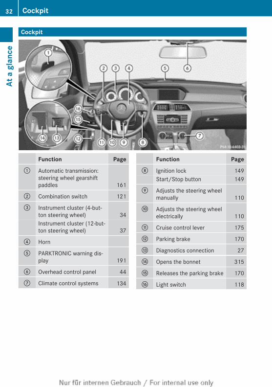
Cockpit
Function Page: Automatic transmission:
steering wheel gearshiftpaddles 161
; Combination switch 121
= Instrument cluster (4-but-ton steering wheel) 34Instrument cluster (12-but-ton steering wheel) 37
? Horn
A PARKTRONIC warning dis-play 191
B Overhead control panel 44
C Climate control systems 134
Function PageD Ignition lock 149
Start/Stop button 149
E Adjusts the steering wheelmanually 110
F Adjusts the steering wheelelectrically 110
G Cruise control lever 175
H Parking brake 170
I Diagnostics connection 27
J Opens the bonnet 315
K Releases the parking brake 170
L Light switch 118
32 CockpitAt
a g
lanc
e
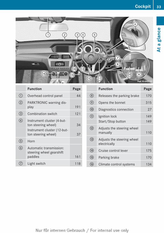
Function Page: Overhead control panel 44
; PARKTRONIC warning dis-play 191
= Combination switch 121
? Instrument cluster (4-but-ton steering wheel) 34Instrument cluster (12-but-ton steering wheel) 37
A Horn
B Automatic transmission:steering wheel gearshiftpaddles 161
C Light switch 118
Function PageD Releases the parking brake 170
E Opens the bonnet 315
F Diagnostics connection 27
G Ignition lock 149Start/Stop button 149
H Adjusts the steering wheelmanually 110
I Adjusts the steering wheelelectrically 110
J Cruise control lever 175
K Parking brake 170
L Climate control systems 134
Cockpit 33
At a
gla
nce
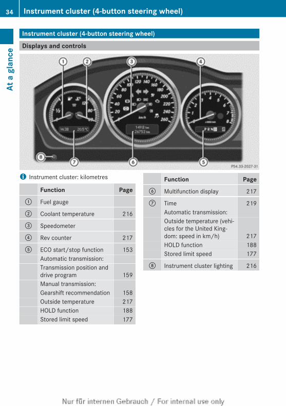
Instrument cluster (4-button steering wheel)
Displays and controls
i Instrument cluster: kilometres
Function Page: Fuel gauge
; Coolant temperature 216
= Speedometer
? Rev counter 217
A ECO start/stop function 153Automatic transmission:Transmission position anddrive program 159Manual transmission:Gearshift recommendation 158Outside temperature 217HOLD function 188Stored limit speed 177
Function PageB Multifunction display 217
C Time 219Automatic transmission:Outside temperature (vehi-cles for the United King-dom: speed in km/h) 217HOLD function 188Stored limit speed 177
D Instrument cluster lighting 216
34 Instrument cluster (4-button steering wheel)At
a g
lanc
e
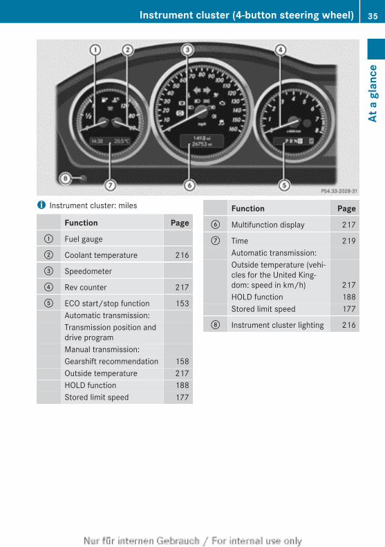
i Instrument cluster: miles
Function Page: Fuel gauge
; Coolant temperature 216
= Speedometer
? Rev counter 217
A ECO start/stop function 153Automatic transmission:Transmission position anddrive programManual transmission:Gearshift recommendation 158Outside temperature 217HOLD function 188Stored limit speed 177
Function PageB Multifunction display 217
C Time 219Automatic transmission:Outside temperature (vehi-cles for the United King-dom: speed in km/h) 217HOLD function 188Stored limit speed 177
D Instrument cluster lighting 216
Instrument cluster (4-button steering wheel) 35
At a
gla
nce
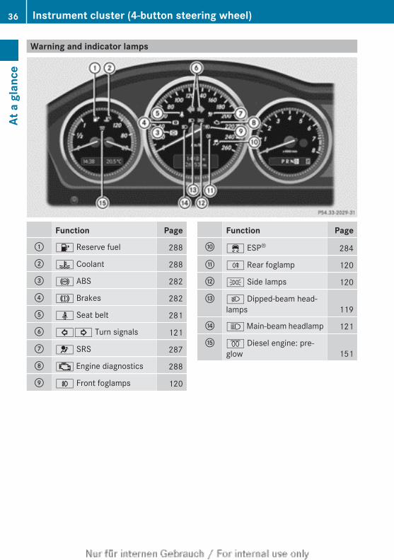
Warning and indicator lamps
Function Page: 8 Reserve fuel 288
; ? Coolant 288
= ! ABS 282
? J Brakes 282
A ü Seat belt 281
B #! Turn signals 121
C 6 SRS 287
D ; Engine diagnostics 288
E N Front foglamps 120
Function PageF ÷ ESP® 284
G R Rear foglamp 120
H T Side lamps 120
I L Dipped-beam head-lamps 119
J K Main-beam headlamp 121
K % Diesel engine: pre-glow 151
36 Instrument cluster (4-button steering wheel)At
a g
lanc
e
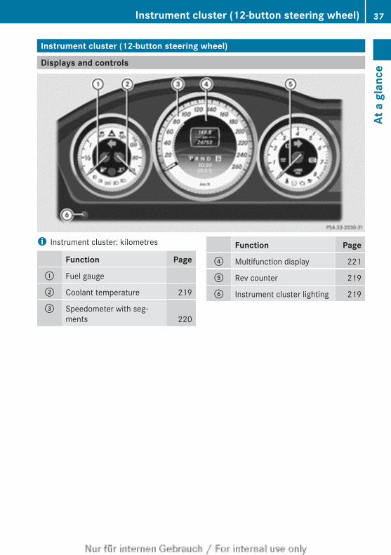
Instrument cluster (12-button steering wheel)
Displays and controls
i Instrument cluster: kilometres
Function Page: Fuel gauge
; Coolant temperature 219
= Speedometer with seg-ments 220
Function Page? Multifunction display 221
A Rev counter 219
B Instrument cluster lighting 219
Instrument cluster (12-button steering wheel) 37
At a
gla
nce
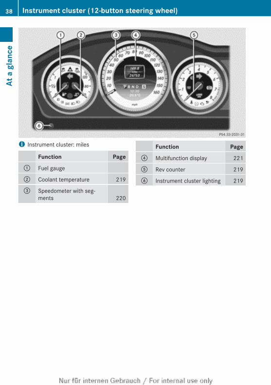
i Instrument cluster: miles
Function Page: Fuel gauge
; Coolant temperature 219
= Speedometer with seg-ments 220
Function Page? Multifunction display 221
A Rev counter 219
B Instrument cluster lighting 219
38 Instrument cluster (12-button steering wheel)At
a g
lanc
e
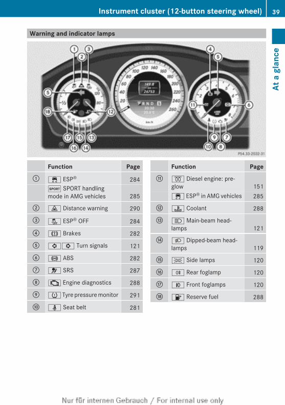
Warning and indicator lamps
Function Page: ÷ ESP® 284
M SPORT handlingmode in AMG vehicles 285
; · Distance warning 290
= å ESP® OFF 284
? J Brakes 282
A #! Turn signals 121
B ! ABS 282
C 6 SRS 287
D ; Engine diagnostics 288
E h Tyre pressure monitor 291
F ü Seat belt 281
Function PageG % Diesel engine: pre-
glow 151÷ ESP® in AMG vehicles 285
H ? Coolant 288
I K Main-beam head-lamps 121
J L Dipped-beam head-lamps 119
K T Side lamps 120
L R Rear foglamp 120
M N Front foglamps 120
N 8 Reserve fuel 288
Instrument cluster (12-button steering wheel) 39
At a
gla
nce
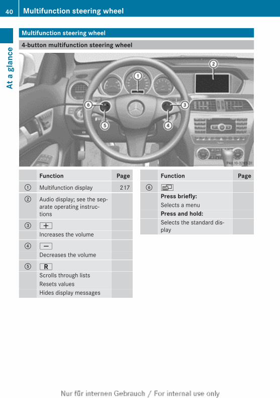
Multifunction steering wheel
4-button multifunction steering wheel
Function Page: Multifunction display 217
; Audio display; see the sep-arate operating instruc-tions
= W
Increases the volume
? X
Decreases the volume
A C
Scrolls through listsResets valuesHides display messages
Function PageB V
Press briefly:Selects a menuPress and hold:Selects the standard dis-play
40 Multifunction steering wheelAt
a g
lanc
e
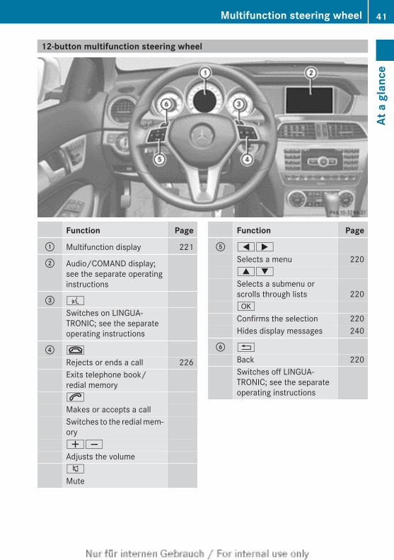
12-button multifunction steering wheel
Function Page: Multifunction display 221
; Audio/COMAND display;see the separate operatinginstructions
= ?
Switches on LINGUA-TRONIC; see the separateoperating instructions
? ~
Rejects or ends a call 226Exits telephone book/redial memory6
Makes or accepts a callSwitches to the redial mem-oryWX
Adjusts the volume8
Mute
Function PageA =;
Selects a menu 2209:
Selects a submenu orscrolls through lists 220a
Confirms the selection 220Hides display messages 240
B %
Back 220Switches off LINGUA-TRONIC; see the separateoperating instructions
Multifunction steering wheel 41
At a
gla
nce
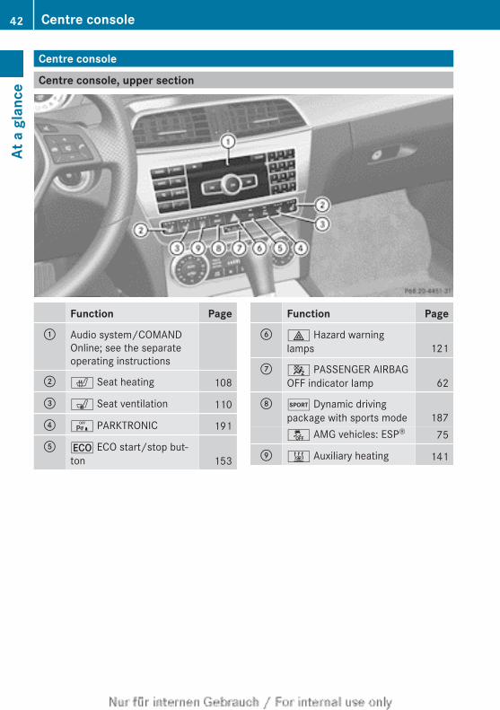
Centre console
Centre console, upper section
Function Page: Audio system/COMAND
Online; see the separateoperating instructions
; c Seat heating 108
= s Seat ventilation 110
? c PARKTRONIC 191
A ¤ ECO start/stop but-ton 153
Function PageB £ Hazard warning
lamps 121
C 4 PASSENGER AIRBAGOFF indicator lamp 62
D M Dynamic drivingpackage with sports mode 187å AMG vehicles: ESP® 75
E & Auxiliary heating 141
42 Centre consoleAt
a g
lanc
e
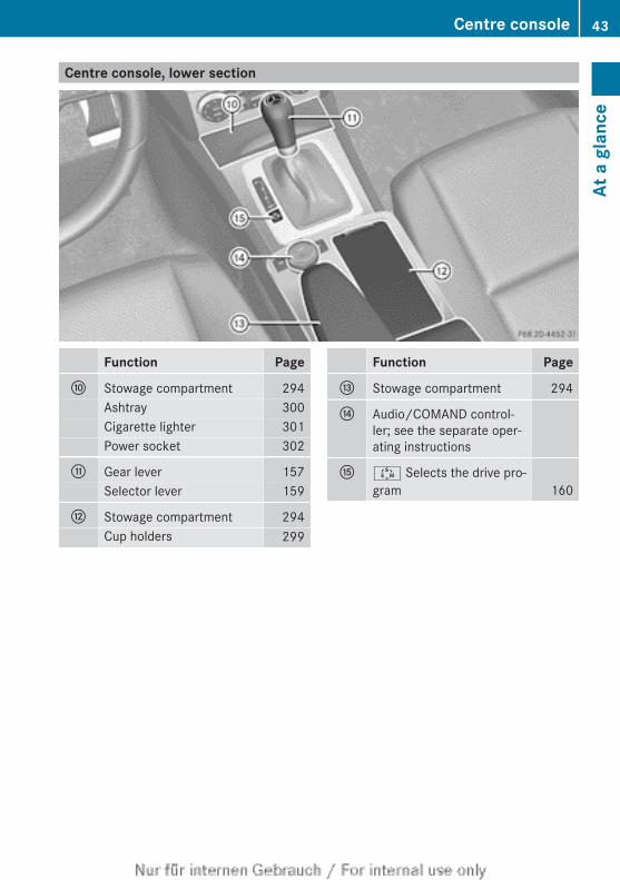
Centre console, lower section
Function PageF Stowage compartment 294
Ashtray 300Cigarette lighter 301Power socket 302
G Gear lever 157Selector lever 159
H Stowage compartment 294Cup holders 299
Function PageI Stowage compartment 294
J Audio/COMAND control-ler; see the separate oper-ating instructions
K Ú Selects the drive pro-gram 160
Centre console 43
At a
gla
nce
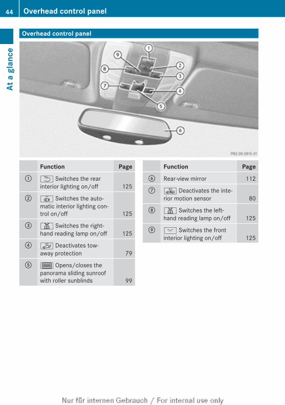
Overhead control panel
Function Page: u Switches the rear
interior lighting on/off 125
; | Switches the auto-matic interior lighting con-trol on/off 125
= p Switches the right-hand reading lamp on/off 125
? ë Deactivates tow-away protection 79
A 3 Opens/closes thepanorama sliding sunroofwith roller sunblinds 99
Function PageB Rear-view mirror 112
C ê Deactivates the inte-rior motion sensor 80
D p Switches the left-hand reading lamp on/off 125
E c Switches the frontinterior lighting on/off 125
44 Overhead control panelAt
a g
lanc
e
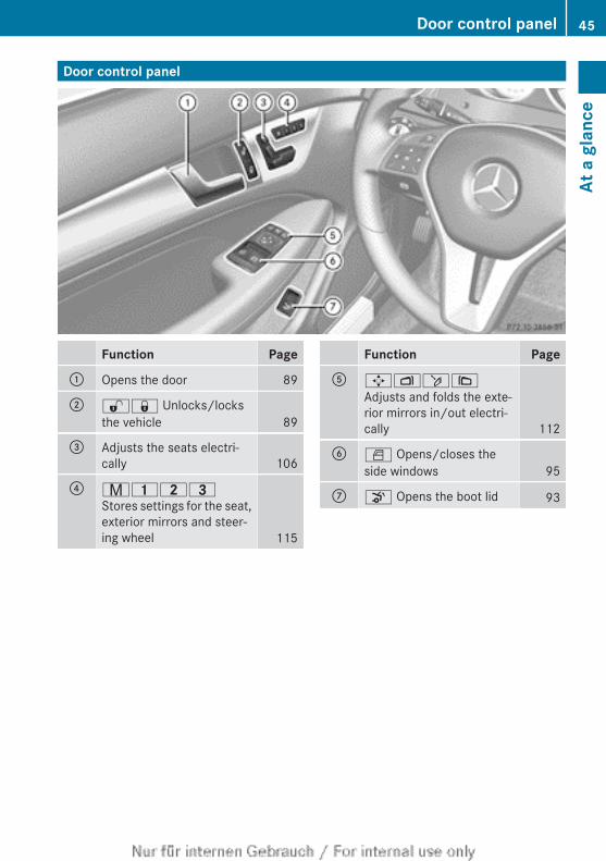
Door control panel
Function Page: Opens the door 89
; %& Unlocks/locksthe vehicle 89
= Adjusts the seats electri-cally 106
? r45=Stores settings for the seat,exterior mirrors and steer-ing wheel 115
Function PageA 7Zö\
Adjusts and folds the exte-rior mirrors in/out electri-cally 112
B W Opens/closes theside windows 95
C o Opens the boot lid 93
Door control panel 45
At a
gla
nce

46
Useful information .............................. 48Panic alarm .......................................... 48Occupant safety .................................. 48Children in the vehicle ........................ 59Driving safety systems ....................... 70Anti-theft systems .............................. 78
47
Safe
ty
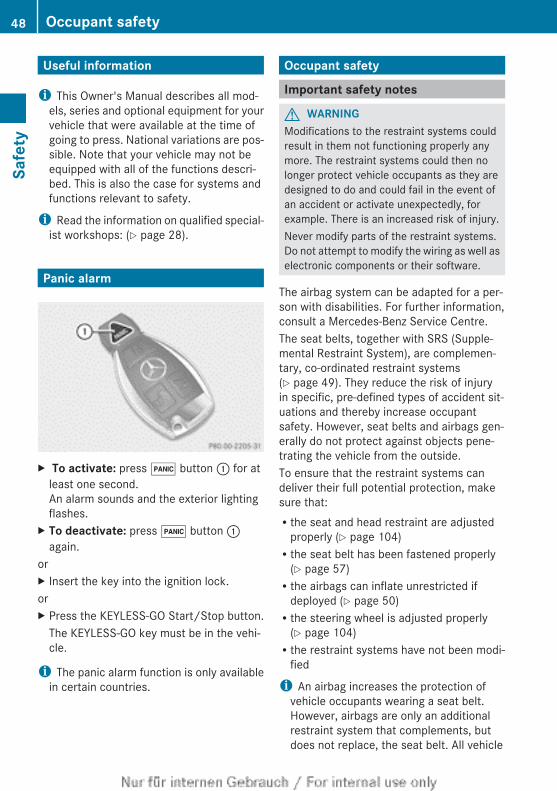
Useful information
i This Owner's Manual describes all mod-els, series and optional equipment for yourvehicle that were available at the time ofgoing to press. National variations are pos-sible. Note that your vehicle may not beequipped with all of the functions descri-bed. This is also the case for systems andfunctions relevant to safety.
i Read the information on qualified special-ist workshops: (Y page 28).
Panic alarm
X To activate: press ! button : for atleast one second.An alarm sounds and the exterior lightingflashes.
X To deactivate: press ! button :again.
orX Insert the key into the ignition lock.orX Press the KEYLESS-GO Start/Stop button.
The KEYLESS-GO key must be in the vehi-cle.
i The panic alarm function is only availablein certain countries.
Occupant safety
Important safety notes
G WARNINGModifications to the restraint systems couldresult in them not functioning properly anymore. The restraint systems could then nolonger protect vehicle occupants as they aredesigned to do and could fail in the event ofan accident or activate unexpectedly, forexample. There is an increased risk of injury.Never modify parts of the restraint systems.Do not attempt to modify the wiring as well aselectronic components or their software.
The airbag system can be adapted for a per-son with disabilities. For further information,consult a Mercedes-Benz Service Centre.The seat belts, together with SRS (Supple-mental Restraint System), are complemen-tary, co-ordinated restraint systems(Y page 49). They reduce the risk of injuryin specific, pre-defined types of accident sit-uations and thereby increase occupantsafety. However, seat belts and airbags gen-erally do not protect against objects pene-trating the vehicle from the outside.To ensure that the restraint systems candeliver their full potential protection, makesure that:Rthe seat and head restraint are adjusted
properly (Y page 104)Rthe seat belt has been fastened properly
(Y page 57)Rthe airbags can inflate unrestricted if
deployed (Y page 50)Rthe steering wheel is adjusted properly
(Y page 104)Rthe restraint systems have not been modi-
fied
i An airbag increases the protection ofvehicle occupants wearing a seat belt.However, airbags are only an additionalrestraint system that complements, butdoes not replace, the seat belt. All vehicle
48 Occupant safetySa
fety
occupants must wear their seat belt cor-rectly at all times, even if the vehicle isequipped with airbags. The airbags are notdeployed in all types of accidents. Forexample, if the protective capacity of cor-rectly fastened seat belts is not increasedby deploying the airbags, the airbags willnot deploy. Airbag deployment only pro-vides increased protection if the seat beltis worn correctly because:Rthe seat belt helps to keep the vehicle
occupant in the best position in relationto the airbag.Rin a head-on collision, for example, the
seat belt prevents the vehicle occupantfrom being propelled towards the pointof impact. It can thus reduce the risk ofinjury.
In accidents in which an airbag is deployed,it provides increased protection only if theseat belt is worn correctly.
SRS (Supplemental Restraint System)
IntroductionSRS consists of:Rthe 6 SRS warning lampRairbagsRairbag control unit (with crash sensors)Rbelt tensionersRbelt force limitersSRS reduces the risk of occupants cominginto contact with the vehicle's interior in theevent of an accident. It can also reduce theforces to which occupants are subjected dur-ing an accident.
SRS warning lamp
G WARNINGIf SRS is malfunctioning, child restraint sys-tem components may be triggered uninten-tionally or might not be triggered at all in theevent of an accident with a high rate of vehicle
deceleration. There is an increased risk ofinjury, possibly even fatal.Have SRS checked and repaired immediatelyat a qualified specialist workshop.
SRS functions are checked regularly whenyou switch on the ignition and when theengine is running. Therefore, malfunctionscan be detected in good time.The 6 SRS warning lamp in the instrumentcluster lights up when the ignition is switchedon. It goes out no later than a few secondsafter the engine is started.The SRS components are in operational read-iness when the 6 SRS warning lamp goesout while the engine is running.A malfunction has occurred if:Rthe 6 SRS warning lamp does not light
up when the ignition is switched onRthe engine is running and the 6 SRS
warning lamp does not go out after a fewsecondsRthe engine is running and the 6 SRS
warning lamp lights up again
Triggering of belt tensioners and air-bagsDuring the first stage of a collision, the airbagcontrol unit evaluates important physicaldata relating to vehicle deceleration or accel-eration, such as:RdurationRdirectionRmagnitudeBased on the evaluation of this data, the air-bag control unit pre-emptively triggers thebelt tensioners in the first stage.
i The front belt tensioners can only be trig-gered if the seat belt tongues on the frontseats are correctly engaged in the seat beltbuckles.
If there is an even higher rate of vehicle decel-eration or acceleration in a longitudinal direc-tion, the front airbags are also deployed.
Occupant safety 49
Safe
ty
Z
Your vehicle has adaptive, two-stage front air-bags. The airbag control unit evaluates vehi-cle deceleration or acceleration in the eventof a collision. In the first deployment stage,the front airbag is filled with enough propel-lant gas to reduce the risk of injuries. Thefront airbag is fully deployed if a seconddeployment threshold is exceeded within afew milliseconds.The belt tensioner and airbag triggeringthresholds are variable and are adapted to therate of deceleration or acceleration of thevehicle. This process is pre-emptive in nature.The triggering process must take place ingood time at the start of the collision.
i Airbags are not deployed in all types ofaccidents. Also, not all airbags aredeployed together in an accident. The dif-ferent airbag systems work independentlyof each other.How the airbag system works is deter-mined by the severity of the collision detec-ted, especially the vehicle deceleration oracceleration, and the apparent type of acci-dent:Rhead-on collisionRside impactRrear impact
The rate of vehicle deceleration or accelera-tion and the direction of the force are essen-tially determined by:Rthe distribution of forces during the colli-
sionRthe collision angleRthe deformation characteristics of the vehi-
cleRthe characteristics of the object with which
the vehicle has collidedFactors which can only be seen and measuredafter a collision has occurred do not play adecisive role in the deployment of an airbag,nor do they provide an indication of airbagdeployment.
The vehicle may be deformed significantly,e.g. the bonnet or the wing, without an airbagbeing deployed. This is the case if only partswhich are relatively easily deformed are affec-ted and the rate of deceleration is not high.Conversely, airbags may be deployed eventhough the vehicle suffers only minor defor-mation. This is the case if, for example, veryrigid vehicle parts such as longitudinal bodymembers are hit, and sufficient decelerationoccurs as a result.
Airbags
Important safety notes
G WARNINGAirbags provide additional protection; theyare not, however, a substitute for seat belts.Observe the following notes to reduce the riskof serious or even fatal injury caused by airbagdeployment:Rall vehicle occupants – in particular, preg-
nant women – must wear their seat beltcorrectly at all times and lean back againstthe backrest, which should be positionedas close to the vertical as possible. Thehead restraint must support the back of thehead at about eye level.Ralways secure children less than
1.50 m tall or under 12 years of age in suit-able child restraint systems.Rall vehicle occupants must select a seat
position that is as far away from the airbagas possible. The driver's seat position mustallow the vehicle to be driven safely. Thedriver's chest should be as far away fromthe centre of the driver's airbag cover aspossible.Rmove the front-passenger seat as far back
as possible. This is especially important ifyou have secured a child in a child restraintsystem on the front-passenger seat.Rvehicle occupants – in particular, children
– must not lean their head into the area of
50 Occupant safetySa
fety
the window in which the sidebag/window-bag is deployed.Rrearward-facing child restraint systems
must not be fitted to the front-passengerseat unless the front-passenger airbag hasbeen disabled. On the front-passengerseat, the front-passenger airbag is disabledif a child restraint system with a trans-ponder for automatic child seat recognitionis fitted to the front-passenger seat in avehicle equipped with automatic child seatrecognition. The 4 PASSENGER AIRBAGOFF indicator lamp must be continuouslylit.If the front-passenger seat of your vehicledoes not have automatic child seat recog-nition, or your rearward-facing childrestraint system does not have a trans-ponder for automatic child seat recogni-tion, children must be secured in a childrestraint system on a suitable seat in therear. If you secure a forward-facing childrestraint system to the front-passengerseat, you must move the front-passengerseat as far back as possible.Rmake sure there are no heavy or sharp-
edged objects in the pockets of clothing.Rdo not lean forwards, e.g. over the cover of
the driver's/front-passenger front airbag,particularly when the vehicle is in motion.Rdo not put your feet on the dashboard.Ronly hold the steering wheel on the outside.
This allows the airbag to be fully deployed.You could be injured if the airbag isdeployed and you are holding the inside ofthe steering wheel.Rdo not lean on the doors from inside the
vehicle.Rmake sure that there are no people, ani-
mals or objects between the vehicle occu-pants and the area where the airbags aredeployed.Rdo not place any objects between the seat
backrest and the door.
Rdo not hang any hard objects, e.g. coathangers, on the grab handles or coat hooks.Rdo not attach accessories, e.g. cup holders,
to the doors.It is not possible to rule out a risk of injurybeing caused by an airbag, due to the highspeed at which the airbag must be deployed.
Airbag deployment slows down and restrictsthe movement of the vehicle occupant.If the airbags are deployed, you will hear abang and a small amount of powder may alsobe released. Only in rare cases will the bangaffect your hearing. The powder that isreleased generally does not constitute ahealth hazard. The 6 SRS warning lamplights up.The airbag installation locations are identifiedby the AIRBAG symbol.
G WARNINGIf you modify the airbag covers or affixobjects, e.g. stickers to them, the airbags mayno longer function as intended. There is anincreased risk of injury.Never modify the airbag covers and do notaffix any objects to them.
G WARNINGUnsuitable seat covers may obstruct or evenprevent deployment of the airbags integratedinto the seats. The airbags may then fail toprotect the vehicle occupants as intended.Operation of the automatic child seat recog-nition may also be impaired. There is anincreased risk of injury, possibly even fatal.Use only seat covers which have been specif-ically approved for the respective seat byMercedes-Benz.
G WARNINGAfter the driver's airbag has been deployed,the airbag parts are hot. There is a risk ofinjury.
Occupant safety 51
Safe
ty
Z
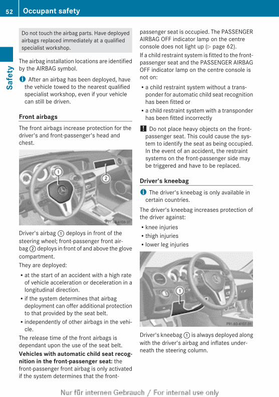
Do not touch the airbag parts. Have deployedairbags replaced immediately at a qualifiedspecialist workshop.
The airbag installation locations are identifiedby the AIRBAG symbol.
i After an airbag has been deployed, havethe vehicle towed to the nearest qualifiedspecialist workshop, even if your vehiclecan still be driven.
Front airbagsThe front airbags increase protection for thedriver's and front-passenger's head andchest.
Driver's airbag : deploys in front of thesteering wheel; front-passenger front air-bag ; deploys in front of and above the glovecompartment.They are deployed:Rat the start of an accident with a high rate
of vehicle acceleration or deceleration in alongitudinal direction.Rif the system determines that airbag
deployment can offer additional protectionto that provided by the seat belt.Rindependently of other airbags in the vehi-
cle.The release time of the front airbags isdependant upon the use of the seat belt.Vehicles with automatic child seat recog-nition in the front-passenger seat: thefront-passenger front airbag is only activatedif the system determines that the front-
passenger seat is occupied. The PASSENGERAIRBAG OFF indicator lamp on the centreconsole does not light up (Y page 62).If a child restraint system is fitted to the front-passenger seat and the PASSENGER AIRBAGOFF indicator lamp on the centre console isnot on:Ra child restraint system without a trans-
ponder for automatic child seat recognitionhas been fitted orRa child restraint system with a transponder
has been fitted incorrectly
! Do not place heavy objects on the front-passenger seat. This could cause the sys-tem to identify the seat as being occupied.In the event of an accident, the restraintsystems on the front-passenger side maybe triggered and have to be replaced.
Driver's kneebagi The driver's kneebag is only available in
certain countries.The driver's kneebag increases protection ofthe driver against:Rknee injuriesRthigh injuriesRlower leg injuries
Driver's kneebag : is always deployed alongwith the driver's airbag and inflates under-neath the steering column.
52 Occupant safetySa
fety
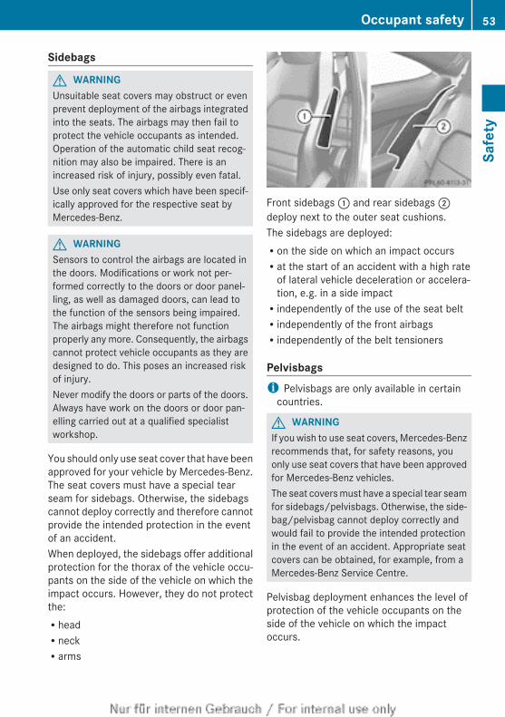
Sidebags
G WARNINGUnsuitable seat covers may obstruct or evenprevent deployment of the airbags integratedinto the seats. The airbags may then fail toprotect the vehicle occupants as intended.Operation of the automatic child seat recog-nition may also be impaired. There is anincreased risk of injury, possibly even fatal.Use only seat covers which have been specif-ically approved for the respective seat byMercedes-Benz.
G WARNINGSensors to control the airbags are located inthe doors. Modifications or work not per-formed correctly to the doors or door panel-ling, as well as damaged doors, can lead tothe function of the sensors being impaired.The airbags might therefore not functionproperly any more. Consequently, the airbagscannot protect vehicle occupants as they aredesigned to do. This poses an increased riskof injury.Never modify the doors or parts of the doors.Always have work on the doors or door pan-elling carried out at a qualified specialistworkshop.
You should only use seat cover that have beenapproved for your vehicle by Mercedes-Benz.The seat covers must have a special tearseam for sidebags. Otherwise, the sidebagscannot deploy correctly and therefore cannotprovide the intended protection in the eventof an accident.When deployed, the sidebags offer additionalprotection for the thorax of the vehicle occu-pants on the side of the vehicle on which theimpact occurs. However, they do not protectthe:RheadRneckRarms
Front sidebags : and rear sidebags ;deploy next to the outer seat cushions.The sidebags are deployed:Ron the side on which an impact occursRat the start of an accident with a high rate
of lateral vehicle deceleration or accelera-tion, e.g. in a side impactRindependently of the use of the seat beltRindependently of the front airbagsRindependently of the belt tensioners
Pelvisbagsi Pelvisbags are only available in certain
countries.
G WARNINGIf you wish to use seat covers, Mercedes-Benzrecommends that, for safety reasons, youonly use seat covers that have been approvedfor Mercedes-Benz vehicles.The seat covers must have a special tear seamfor sidebags/pelvisbags. Otherwise, the side-bag/pelvisbag cannot deploy correctly andwould fail to provide the intended protectionin the event of an accident. Appropriate seatcovers can be obtained, for example, from aMercedes-Benz Service Centre.
Pelvisbag deployment enhances the level ofprotection of the vehicle occupants on theside of the vehicle on which the impactoccurs.
Occupant safety 53
Safe
ty
Z
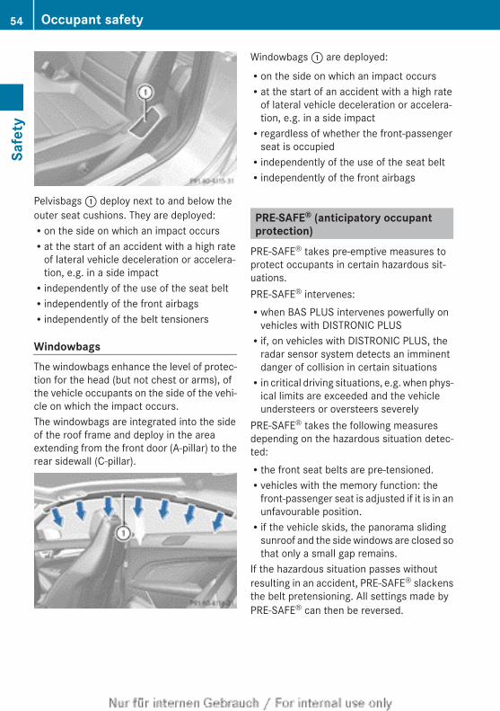
Pelvisbags : deploy next to and below theouter seat cushions. They are deployed:Ron the side on which an impact occursRat the start of an accident with a high rate
of lateral vehicle deceleration or accelera-tion, e.g. in a side impactRindependently of the use of the seat beltRindependently of the front airbagsRindependently of the belt tensioners
WindowbagsThe windowbags enhance the level of protec-tion for the head (but not chest or arms), ofthe vehicle occupants on the side of the vehi-cle on which the impact occurs.The windowbags are integrated into the sideof the roof frame and deploy in the areaextending from the front door (A-pillar) to therear sidewall (C-pillar).
Windowbags : are deployed:Ron the side on which an impact occursRat the start of an accident with a high rate
of lateral vehicle deceleration or accelera-tion, e.g. in a side impactRregardless of whether the front-passenger
seat is occupiedRindependently of the use of the seat beltRindependently of the front airbags
PRE-SAFE® (anticipatory occupantprotection)
PRE-SAFE® takes pre-emptive measures toprotect occupants in certain hazardous sit-uations.PRE-SAFE® intervenes:Rwhen BAS PLUS intervenes powerfully on
vehicles with DISTRONIC PLUSRif, on vehicles with DISTRONIC PLUS, the
radar sensor system detects an imminentdanger of collision in certain situationsRin critical driving situations, e.g. when phys-
ical limits are exceeded and the vehicleundersteers or oversteers severely
PRE-SAFE® takes the following measuresdepending on the hazardous situation detec-ted:Rthe front seat belts are pre-tensioned.Rvehicles with the memory function: the
front-passenger seat is adjusted if it is in anunfavourable position.Rif the vehicle skids, the panorama sliding
sunroof and the side windows are closed sothat only a small gap remains.
If the hazardous situation passes withoutresulting in an accident, PRE-SAFE® slackensthe belt pretensioning. All settings made byPRE-SAFE® can then be reversed.
54 Occupant safetySa
fety
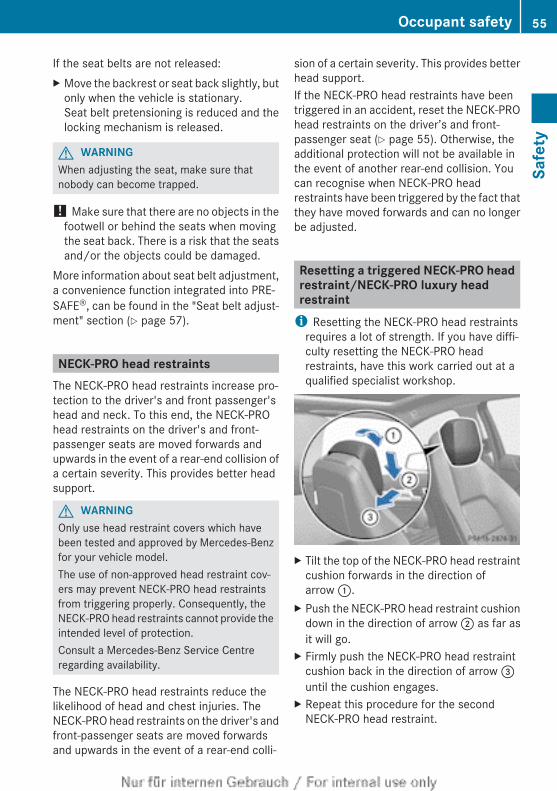
If the seat belts are not released:X Move the backrest or seat back slightly, but
only when the vehicle is stationary.Seat belt pretensioning is reduced and thelocking mechanism is released.
G WARNINGWhen adjusting the seat, make sure thatnobody can become trapped.
! Make sure that there are no objects in thefootwell or behind the seats when movingthe seat back. There is a risk that the seatsand/or the objects could be damaged.
More information about seat belt adjustment,a convenience function integrated into PRE-SAFE®, can be found in the "Seat belt adjust-ment" section (Y page 57).
NECK-PRO head restraintsThe NECK-PRO head restraints increase pro-tection to the driver's and front passenger'shead and neck. To this end, the NECK-PROhead restraints on the driver's and front-passenger seats are moved forwards andupwards in the event of a rear-end collision ofa certain severity. This provides better headsupport.
G WARNINGOnly use head restraint covers which havebeen tested and approved by Mercedes-Benzfor your vehicle model.The use of non-approved head restraint cov-ers may prevent NECK-PRO head restraintsfrom triggering properly. Consequently, theNECK-PRO head restraints cannot provide theintended level of protection.Consult a Mercedes-Benz Service Centreregarding availability.
The NECK-PRO head restraints reduce thelikelihood of head and chest injuries. TheNECK-PRO head restraints on the driver's andfront-passenger seats are moved forwardsand upwards in the event of a rear-end colli-
sion of a certain severity. This provides betterhead support.If the NECK-PRO head restraints have beentriggered in an accident, reset the NECK-PROhead restraints on the driver’s and front-passenger seat (Y page 55). Otherwise, theadditional protection will not be available inthe event of another rear-end collision. Youcan recognise when NECK-PRO headrestraints have been triggered by the fact thatthey have moved forwards and can no longerbe adjusted.
Resetting a triggered NECK-PRO headrestraint/NECK-PRO luxury headrestraint
i Resetting the NECK-PRO head restraintsrequires a lot of strength. If you have diffi-culty resetting the NECK-PRO headrestraints, have this work carried out at aqualified specialist workshop.
X Tilt the top of the NECK-PRO head restraintcushion forwards in the direction ofarrow :.
X Push the NECK-PRO head restraint cushiondown in the direction of arrow ; as far asit will go.
X Firmly push the NECK-PRO head restraintcushion back in the direction of arrow =until the cushion engages.
X Repeat this procedure for the secondNECK-PRO head restraint.
Occupant safety 55
Safe
ty
Z
Seat belts
Important safety notesSeat belts are the most effective means ofrestraining the movement of vehicle occu-pants in the event of an accident. Thisreduces the risk of vehicle occupants cominginto contact with parts of the vehicle interior.
G WARNINGA seat belt which is not worn correctly, orwhich has not been engaged in the seat beltbuckle correctly, cannot provide the intendedlevel of protection. Under certain circumstan-ces, this could cause severe or even fatal inju-ries in the event of an accident.Therefore, make sure that all occupants — inparticular, pregnant women — wear their seatbelts correctly at all times.RThe seat belt must fit snugly on your body
and must not be twisted.Therefore, avoidwearing bulky clothing, e.g. a winter coat.The shoulder section of the belt must berouted across the centre of your shoulder— on no account across your neck or underyour arm — and pulled tight against yourupper body. The lap belt must always passacross your lap as low down as possible, i.e.over your hip joints — not across your abdo-men. If necessary, push the seat beltslightly downwards and adjust it by pullingit in the direction the seat belt retracts.RDo not route the seat belt strap over sharp
or fragile objects. Please make sure thatsuch objects are not on or in your clothing,e.g. spectacles, pens or keys etc. The seatbelt strap could become damaged and tearduring an accident and you or other vehicleoccupants could be injured.ROnly one person should use each seat belt
at any one time. Children must never travelsitting on the lap of another occupant. Thechild will not be secured in the event of anaccident, heavy braking or sudden changeof direction. This may result in the child or
other occupants being seriously or fatallyinjured.RPersons under 1.50 m tall cannot wear the
seat belts correctly. For this reason securepersons less than 1.50 m tall in speciallydesigned, suitable restraint systems.RChildren under 1.50 m tall and younger
than twelve years of age cannot wear theseat belts correctly. For this reason securethem in special suitable child restraint sys-tems installed on a suitable seat. Additionalinformation can be found in the OperatingInstructions in the chapter "Safety", "Chil-dren in the Vehicle". Observe the installa-tion instructions of the child restraint sys-tem manufacturer.RDo not secure an object with a seat belt if
the seat belt is also being used by one ofthe vehicle's occupants.
G WARNINGThe seat belt does not offer the intended levelof protection if the backrest is not in theupright position. When braking or in the eventof an accident, you could slide underneath theseat belt and sustain abdomen or neck inju-ries, for example. This poses an increased riskof injury or even fatal injury.Adjust the seat properly before beginningyour journey. Always make sure that the seatis in the upright position.
G WARNINGSeat belts cannot perform their intended pro-tective function if:Rthey are damaged, modified, bleached or
coloured, or are very dirtyRthe seat belt buckle is damaged or very
dirtyRmodifications have been made to the seat
belt tensioners or belt anchoragesIn the event of an accident, seat belts cansustain damage that is not visible to the nakedeye, e. g. due to glass splinters. Modified ordamaged seat belts could tear or fail in the
56 Occupant safetySa
fety
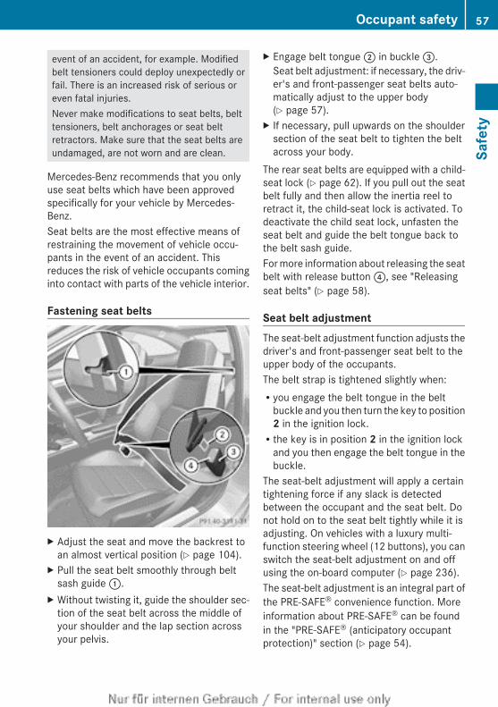
event of an accident, for example. Modifiedbelt tensioners could deploy unexpectedly orfail. There is an increased risk of serious oreven fatal injuries.Never make modifications to seat belts, belttensioners, belt anchorages or seat beltretractors. Make sure that the seat belts areundamaged, are not worn and are clean.
Mercedes-Benz recommends that you onlyuse seat belts which have been approvedspecifically for your vehicle by Mercedes-Benz.Seat belts are the most effective means ofrestraining the movement of vehicle occu-pants in the event of an accident. Thisreduces the risk of vehicle occupants cominginto contact with parts of the vehicle interior.
Fastening seat belts
X Adjust the seat and move the backrest toan almost vertical position (Y page 104).
X Pull the seat belt smoothly through beltsash guide :.
X Without twisting it, guide the shoulder sec-tion of the seat belt across the middle ofyour shoulder and the lap section acrossyour pelvis.
X Engage belt tongue ; in buckle =.Seat belt adjustment: if necessary, the driv-er's and front-passenger seat belts auto-matically adjust to the upper body(Y page 57).
X If necessary, pull upwards on the shouldersection of the seat belt to tighten the beltacross your body.
The rear seat belts are equipped with a child-seat lock (Y page 62). If you pull out the seatbelt fully and then allow the inertia reel toretract it, the child-seat lock is activated. Todeactivate the child seat lock, unfasten theseat belt and guide the belt tongue back tothe belt sash guide.For more information about releasing the seatbelt with release button ?, see "Releasingseat belts" (Y page 58).
Seat belt adjustmentThe seat-belt adjustment function adjusts thedriver's and front-passenger seat belt to theupper body of the occupants.The belt strap is tightened slightly when:Ryou engage the belt tongue in the belt
buckle and you then turn the key to position2 in the ignition lock.Rthe key is in position 2 in the ignition lock
and you then engage the belt tongue in thebuckle.
The seat-belt adjustment will apply a certaintightening force if any slack is detectedbetween the occupant and the seat belt. Donot hold on to the seat belt tightly while it isadjusting. On vehicles with a luxury multi-function steering wheel (12 buttons), you canswitch the seat-belt adjustment on and offusing the on-board computer (Y page 236).The seat-belt adjustment is an integral part ofthe PRE-SAFE® convenience function. Moreinformation about PRE-SAFE® can be foundin the "PRE-SAFE® (anticipatory occupantprotection)" section (Y page 54).
Occupant safety 57
Safe
ty
Z
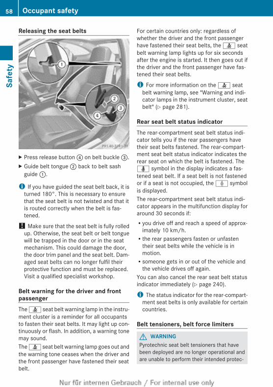
Releasing the seat belts
X Press release button ? on belt buckle =.X Guide belt tongue ; back to belt sash
guide :.
i If you have guided the seat belt back, it isturned 180°. This is necessary to ensurethat the seat belt is not twisted and that itis routed correctly when the belt is fas-tened.
! Make sure that the seat belt is fully rolledup. Otherwise, the seat belt or belt tonguewill be trapped in the door or in the seatmechanism. This could damage the door,the door trim panel and the seat belt. Dam-aged seat belts can no longer fulfil theirprotective function and must be replaced.Visit a qualified specialist workshop.
Belt warning for the driver and frontpassengerThe 7 seat belt warning lamp in the instru-ment cluster is a reminder for all occupantsto fasten their seat belts. It may light up con-tinuously or flash. In addition, a warning tonemay sound.The 7 seat belt warning lamp goes out andthe warning tone ceases when the driver andthe front passenger have fastened their seatbelt.
For certain countries only: regardless ofwhether the driver and the front passengerhave fastened their seat belts, the 7 seatbelt warning lamp lights up for six secondsafter the engine is started. It then goes out ifthe driver and the front passenger have fas-tened their seat belts.
i For more information on the 7 seatbelt warning lamp, see "Warning and indi-cator lamps in the instrument cluster, seatbelt" (Y page 281).
Rear seat belt status indicatorThe rear-compartment seat belt status indi-cator tells you if the rear passengers havetheir seat belts fastened. The rear-compart-ment seat belt status indicator indicates therear seat on which the belt is fastened. Theü symbol in the display indicates a fas-tened seat belt. If a seat belt is not fastenedor if a seat is not occupied, the ý symbolis displayed.The rear-compartment seat belt status indi-cator appears in the multifunction display foraround 30 seconds if:Ryou drive off and reach a speed of approx-
imately 10 km/h.Rthe rear passengers fasten or unfasten
their seat belts while the vehicle is inmotion.Rsomeone gets in or out of the vehicle and
the vehicle drives off again.You can also cancel the rear seat belt statusindicator immediately (Y page 240).
i The status indicator for the rear-compart-ment seat belts is only available for certaincountries.
Belt tensioners, belt force limiters
G WARNINGPyrotechnic seat belt tensioners that havebeen deployed are no longer operational andare unable to perform their intended protec-
58 Occupant safetySa
fety
tive function. This poses an increased risk ofinjury or even fatal injury.Therefore, have pyrotechnic belt tensionerswhich have been triggered immediatelyreplaced at a qualified specialist workshop.
! If the front-passenger seat is not occu-pied, do not engage the seat belt tongue inthe buckle on the front-passenger seat.Otherwise, the belt tensioner could be trig-gered in the event of an accident.
i Vehicles with PRE-SAFE®: belt tensionersthat are triggered by an electric motor canbe deployed as often as desired and do notneed to be replaced.
The seat belts are fitted with belt tensioners.The belt tensioners tighten the seat belts inan accident, pulling them close against thebody.Belt tensioners do not correct incorrect seatpositions or incorrectly fastened seat belts.Belt tensioners do not pull vehicle occupantsback towards the backrest.The belt tensioners can only be activatedwhen:Rthe ignition is switched onRthe restraint systems are operational; see
"SRS warning lamp" (Y page 49)Rthe belt tongue is engaged in the buckle on
each of the three-point seat belts in frontThe belt tensioners on the seats in the rearcompartment are triggered independently ofthe lock status of the seat belts.The belt tensioners are triggered dependingon the type and severity of an accident:Rif, in the event of a head-on or rear-end col-
lision the vehicle decelerates or acceler-ates rapidly in a longitudinal direction dur-ing the initial stages of the impactRif, in the event of a side impact, on the side
opposite the impact the vehicle deceler-ates or accelerates rapidly in a lateral direc-tion
If the airbags are deployed, you will hear abang, and a small amount of powder may alsobe released. Only in rare cases will the bangaffect your hearing. The powder that isreleased generally does not constitute ahealth hazard and does not indicate that thereis a fire in the vehicle. The powder may causeshort-term breathing difficulties to personssuffering from asthma or other pulmonaryconditions. In order to prevent potentialbreathing difficulties, you should leave thevehicle as soon as it is safe to do so. You canalso open the window to allow fresh air toenter the vehicle interior. The 6 SRS warn-ing lamp lights up.If the seat belt is also fitted with a belt forcelimiter and this is triggered, the force exertedby the seat belt on the vehicle occupant isreduced.The belt force limiters on the front seats aresynchronised with the front airbags, whichtake on a part of the deceleration force. Thisresults in the load being distributed over agreater area.
Children in the vehicle
Child restraint systems
Important safety notes
G WARNINGTo reduce the risk of serious or even fatalinjury to the child in the event of a suddenchange in direction, braking or an accident:RChildren less than 1.50 m tall and under
twelve years of age must always be securedin special child restraint systems on a suit-able vehicle seat. This is necessarybecause the seat belts are not designed forchildren.RDo not transport children who are secured
in rearward-facing child restraint systemson the front-passenger seat. Exception: ifthe vehicle is equipped with automatic childseat recognition on the front-passenger
Children in the vehicle 59
Safe
ty
Z
seat and the child is secured in a childrestraint system with transponders forautomatic child seat recognitionRIf you secure a forward-facing child
restraint system to the front-passengerseat, you must move the front-passengerseat as far back as possible. When doingso, ensure that the shoulder belt strap fromthe belt outlet on the vehicle is routedtowards the front to the shoulder belt guideon the child restraint system. Set the beltheight adjustment so that the belt strap isrouted towards the front along the bottom.RChildren must never travel sitting on the lap
of another occupant. Due to the forceswhich occur in the event of a suddenchange of direction, heavy braking or anaccident, it would not be possible torestrain the child. The child could be thrownagainst parts of the vehicle interior and beseriously or even fatally injured.
G WARNINGIf the child restraint system is incorrectly fit-ted on the seat position suitable for this pur-pose, it cannot perform its intended protec-tive function. In the event of an accident,sharp braking or a sudden change in direction,the child may not be held securely. There isan increased risk of serious or even fatal inju-ries.Observe the manufacturer's installationinstructions and the correct use for the childrestraint system. Make sure that the entiresurface of the child restraint system is restingon the seat surface. Never place objectsunder or behind the child restraint system,e.g. cushions. Only use child restraint sys-tems with the original cover designed forthem. Only replace damaged covers with gen-uine covers.
G WARNINGIf the child restraint system is fitted incor-rectly or is not secured, it can come loose inthe event of an accident, heavy braking or a
sudden change in direction. The childrestraint system could be thrown about, strik-ing vehicle occupants. There is an increasedrisk of injury, possibly even fatal.Always fit child restraint systems properly,even if they are not being used. Make surethat you observe the child restraint systemmanufacturer's installation instructions.
G WARNINGChild restraint systems or their securing sys-tems that have been damaged or subjected toa load in an accident cannot perform theirintended protective function. In the event ofan accident, sharp braking or a suddenchange in direction, the child may not be heldsecurely. There is an increased risk of seriousor even fatal injuries.Immediately replace child restraint systemsthat have been damaged or subjected to aload in an accident. Have the child restraintsecuring systems checked in a qualified spe-cialist workshop before fitting a child restraintsystem again.
G WARNINGIf children are left unsupervised in the vehicle,they could:Ropen the doors, thus endangering other
people or road users.Rget out and disrupt traffic.Roperate the vehicle's equipment.Additionally, children could set the vehicle inmotion if, for example, they:Rrelease the parking brake.Rshift the automatic transmission out of
parking position P.Rshift the manual transmission into neutral.Rstart the engine.There is a risk of an accident and injury.When leaving the vehicle, always take the keywith you and lock the vehicle. Never leavechildren or animals unattended in the vehicle.Always keep the key out of reach of children.
60 Children in the vehicleSa
fety
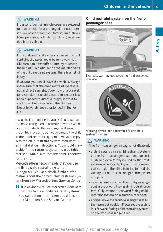
G WARNINGIf persons (particularly children) are exposedto heat or cold for a prolonged period, thereis a risk of serious or even fatal injuries. Neverleave persons (particularly children) unatten-ded in the vehicle.
G WARNINGIf the child restraint system is placed in directsunlight, the parts could become very hot.Children could be suffer burns by touchingthese parts, in particular on the metallic partsof the child restraint system. There is a risk ofinjury.If you and your child leave the vehicle, alwaysmake sure that the child restraint system isnot in direct sunlight. Cover it with a blanket,for example. If the child restraint system hasbeen exposed to direct sunlight, leave it tocool down before securing the child in it.Never leave children unattended in the vehi-cle.
If a child is travelling in your vehicle, securethe child using a child restraint system whichis appropriate to the size, age and weight ofthe child. In order to correctly secure the childin the child restraint system, always complywith the child restraint system manufactur-er's installation instructions. You should pref-erably fit the restraint system to a suitablerear seat. Make sure that the child is securedfor the trip.Mercedes-Benz recommends that you usethe listed child restraint systems(Y page 68). You can obtain further infor-mation about the correct child restraint sys-tem from any Mercedes-Benz Service Centre.
i It is advisable to use Mercedes-Benz careproducts to clean child restraint systems.You can obtain information about this atany Mercedes-Benz Service Centre.
Child restraint system on the front-passenger seat
Example: warning notice on the front-passengersun visor
Warning symbol for a rearward-facing childrestraint system
G WARNINGIf the front-passenger airbag is not disabled:Ra child secured in a child restraint system
on the front-passenger seat could be seri-ously and even fatally injured by the front-passenger airbag deploying. This is espe-cially a risk if the child is in the immediatevicinity of the front-passenger airbag whenit deploys.Rnever secure a child on the front-passenger
seat in a rearward-facing child restraint sys-tem. Only secure a rearward-facing childrestraint system on a suitable rear seat.Ralways move the front-passenger seat to
the rearmost position if you secure a childin a forward-facing child restraint systemon the front-passenger seat.
Children in the vehicle 61
Safe
ty
Z
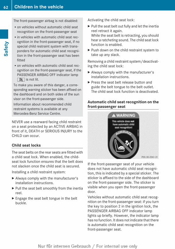
The front-passenger airbag is not disabled:Ron vehicles without automatic child seat
recognition on the front-passenger seatRin vehicles with automatic child seat rec-
ognition in the front-passenger seat, if nospecial child restraint system with trans-ponders for automatic child seat recogni-tion in the front-passenger seat has beenfittedRon vehicles with automatic child seat rec-
ognition on the front-passenger seat, if thePASSENGER AIRBAG OFF indicator lamp4 is not lit.
To make you aware of this danger, a corre-sponding warning sticker has been affixed onthe dashboard and on both sides of the sunvisor on the front-passenger side.Information about recommended childrestraint systems is available at anyMercedes-Benz Service Centre.
NEVER use a rearward facing child restrainton a seat protected by an ACTIVE AIRBAG infront of it, DEATH or SERIOUS INJURY to theCHILD can occur.
Child seat locksThe seat belts on the rear seats are fitted witha child seat lock. When enabled, the child-seat lock function ensures that the belt doesnot slacken once the child seat is secured.Installing a child restraint system:X Always comply with the manufacturer's
installation instructions.X Pull the seat belt smoothly from the inertia
reel.X Engage the seat belt tongue in the belt
buckle.
Activating the child seat lock:X Pull the seat belt out fully and let the inertia
reel retract it again.While the seat belt is retracting, you shouldhear a ratcheting sound. The child seat lockfunction is enabled.
X Push down on the child restraint system totake up any slack.
Removing a child restraint system/deactivat-ing the child seat lock:X Always comply with the manufacturer's
installation instructions.X Press the seat belt release button and
guide the belt tongue to the belt outlet.The child seat lock function is deactivated.
Automatic child seat recognition on thefront-passenger seat
If the front-passenger seat of your vehicledoes not have automatic child seat recogni-tion, this is indicated by a special sticker. Thesticker is affixed to the side of the dashboardon the front-passenger side. The sticker isvisible when you open the front-passengerdoor.Vehicles without automatic child seat recog-nition on the front-passenger seat: if you turnthe key to position 2 in the ignition lock, thePASSENGER AIRBAG OFF indicator lamplights up briefly. However, the indicator lamphas no function. It does not indicate that thereis automatic child seat recognition on thefront-passenger seat.
62 Children in the vehicleSa
fety
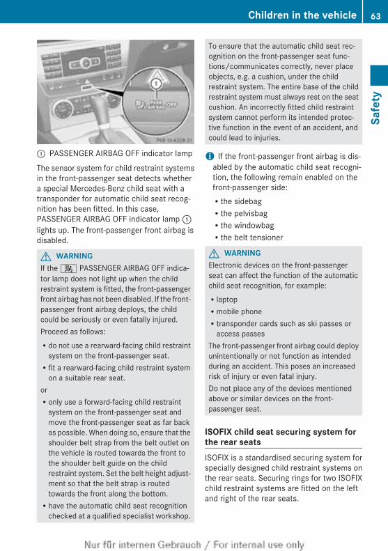
: PASSENGER AIRBAG OFF indicator lamp
The sensor system for child restraint systemsin the front-passenger seat detects whethera special Mercedes-Benz child seat with atransponder for automatic child seat recog-nition has been fitted. In this case,PASSENGER AIRBAG OFF indicator lamp :lights up. The front-passenger front airbag isdisabled.
G WARNINGIf the 4 PASSENGER AIRBAG OFF indica-tor lamp does not light up when the childrestraint system is fitted, the front-passengerfront airbag has not been disabled. If the front-passenger front airbag deploys, the childcould be seriously or even fatally injured.Proceed as follows:Rdo not use a rearward-facing child restraint
system on the front-passenger seat.Rfit a rearward-facing child restraint system
on a suitable rear seat.orRonly use a forward-facing child restraint
system on the front-passenger seat andmove the front-passenger seat as far backas possible. When doing so, ensure that theshoulder belt strap from the belt outlet onthe vehicle is routed towards the front tothe shoulder belt guide on the childrestraint system. Set the belt height adjust-ment so that the belt strap is routedtowards the front along the bottom.Rhave the automatic child seat recognition
checked at a qualified specialist workshop.
To ensure that the automatic child seat rec-ognition on the front-passenger seat func-tions/communicates correctly, never placeobjects, e.g. a cushion, under the childrestraint system. The entire base of the childrestraint system must always rest on the seatcushion. An incorrectly fitted child restraintsystem cannot perform its intended protec-tive function in the event of an accident, andcould lead to injuries.
i If the front-passenger front airbag is dis-abled by the automatic child seat recogni-tion, the following remain enabled on thefront-passenger side:Rthe sidebagRthe pelvisbagRthe windowbagRthe belt tensioner
G WARNINGElectronic devices on the front-passengerseat can affect the function of the automaticchild seat recognition, for example:RlaptopRmobile phoneRtransponder cards such as ski passes or
access passesThe front-passenger front airbag could deployunintentionally or not function as intendedduring an accident. This poses an increasedrisk of injury or even fatal injury.Do not place any of the devices mentionedabove or similar devices on the front-passenger seat.
ISOFIX child seat securing system forthe rear seatsISOFIX is a standardised securing system forspecially designed child restraint systems onthe rear seats. Securing rings for two ISOFIXchild restraint systems are fitted on the leftand right of the rear seats.
Children in the vehicle 63
Safe
ty
Z
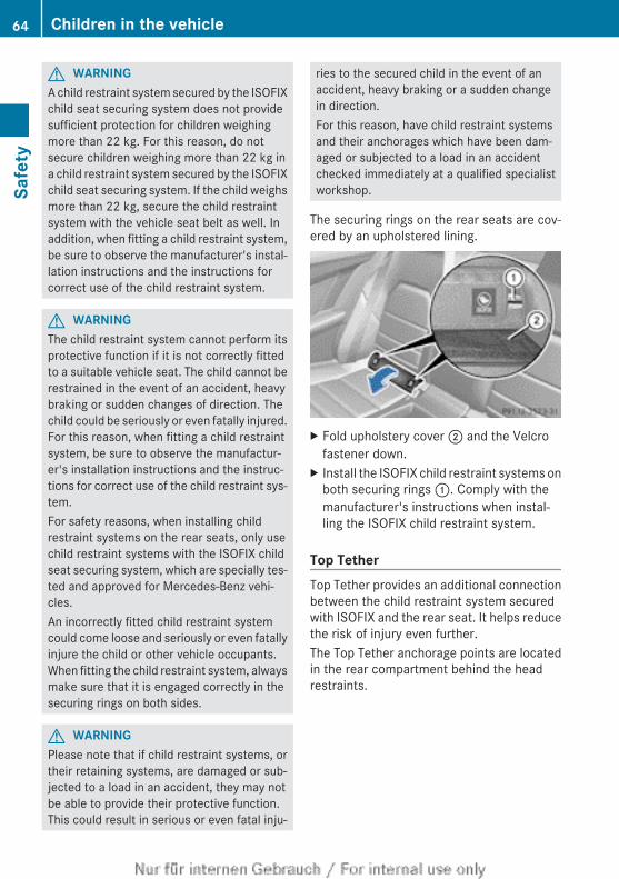
G WARNINGA child restraint system secured by the ISOFIXchild seat securing system does not providesufficient protection for children weighingmore than 22 kg. For this reason, do notsecure children weighing more than 22 kg ina child restraint system secured by the ISOFIXchild seat securing system. If the child weighsmore than 22 kg, secure the child restraintsystem with the vehicle seat belt as well. Inaddition, when fitting a child restraint system,be sure to observe the manufacturer's instal-lation instructions and the instructions forcorrect use of the child restraint system.
G WARNINGThe child restraint system cannot perform itsprotective function if it is not correctly fittedto a suitable vehicle seat. The child cannot berestrained in the event of an accident, heavybraking or sudden changes of direction. Thechild could be seriously or even fatally injured.For this reason, when fitting a child restraintsystem, be sure to observe the manufactur-er's installation instructions and the instruc-tions for correct use of the child restraint sys-tem.For safety reasons, when installing childrestraint systems on the rear seats, only usechild restraint systems with the ISOFIX childseat securing system, which are specially tes-ted and approved for Mercedes-Benz vehi-cles.An incorrectly fitted child restraint systemcould come loose and seriously or even fatallyinjure the child or other vehicle occupants.When fitting the child restraint system, alwaysmake sure that it is engaged correctly in thesecuring rings on both sides.
G WARNINGPlease note that if child restraint systems, ortheir retaining systems, are damaged or sub-jected to a load in an accident, they may notbe able to provide their protective function.This could result in serious or even fatal inju-
ries to the secured child in the event of anaccident, heavy braking or a sudden changein direction.For this reason, have child restraint systemsand their anchorages which have been dam-aged or subjected to a load in an accidentchecked immediately at a qualified specialistworkshop.
The securing rings on the rear seats are cov-ered by an upholstered lining.
X Fold upholstery cover ; and the Velcrofastener down.
X Install the ISOFIX child restraint systems onboth securing rings :. Comply with themanufacturer's instructions when instal-ling the ISOFIX child restraint system.
Top TetherTop Tether provides an additional connectionbetween the child restraint system securedwith ISOFIX and the rear seat. It helps reducethe risk of injury even further.The Top Tether anchorage points are locatedin the rear compartment behind the headrestraints.
64 Children in the vehicleSa
fety
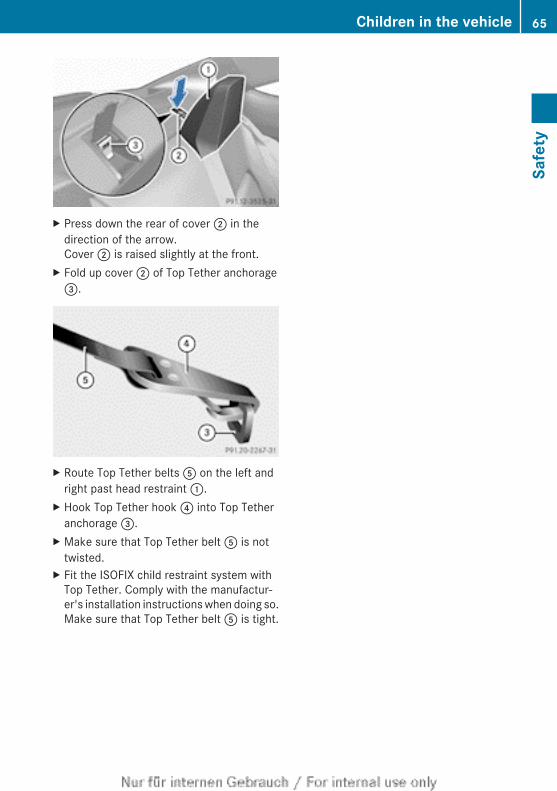
X Press down the rear of cover ; in thedirection of the arrow.Cover ; is raised slightly at the front.
X Fold up cover ; of Top Tether anchorage=.
X Route Top Tether belts A on the left andright past head restraint :.
X Hook Top Tether hook ? into Top Tetheranchorage =.
X Make sure that Top Tether belt A is nottwisted.
X Fit the ISOFIX child restraint system withTop Tether. Comply with the manufactur-er's installation instructions when doing so.Make sure that Top Tether belt A is tight.
Children in the vehicle 65
Safe
ty
Z
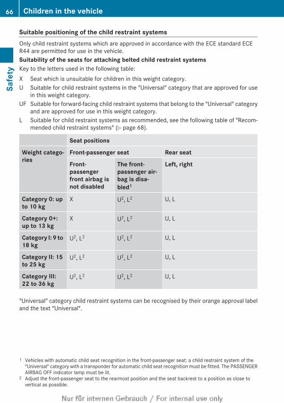
Suitable positioning of the child restraint systemsOnly child restraint systems which are approved in accordance with the ECE standard ECER44 are permitted for use in the vehicle.Suitability of the seats for attaching belted child restraint systemsKey to the letters used in the following table:X Seat which is unsuitable for children in this weight category.U Suitable for child restraint systems in the "Universal" category that are approved for use
in this weight category.UF Suitable for forward-facing child restraint systems that belong to the "Universal" category
and are approved for use in this weight category.L Suitable for child restraint systems as recommended, see the following table of "Recom-
mended child restraint systems" (Y page 68).
Seat positions
Weight catego-ries
Front-passenger seat Rear seat
Front-passenger front airbag is not disabled
The front-passenger air-bag is disa-bled1
Left, right
Category 0: up to 10 kg
X U2, L2 U, L
Category 0+: up to 13 kg
X U2, L2 U, L
Category I: 9 to 18 kg
U2, L2 U2, L2 U, L
Category II: 15 to 25 kg
U2, L2 U2, L2 U, L
Category III: 22 to 36 kg
U2, L2 U2, L2 U, L
"Universal" category child restraint systems can be recognised by their orange approval labeland the text "Universal".
1 Vehicles with automatic child seat recognition in the front-passenger seat: a child restraint system of the"Universal" category with a transponder for automatic child seat recognition must be fitted. The PASSENGERAIRBAG OFF indicator lamp must be lit.
2 Adjust the front-passenger seat to the rearmost position and the seat backrest to a position as close tovertical as possible.
66 Children in the vehicleSa
fety
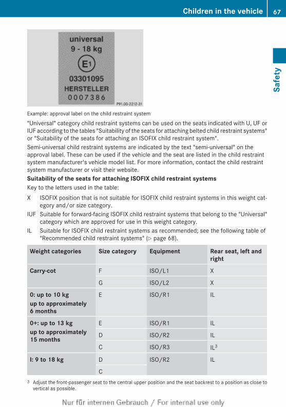
Example: approval label on the child restraint system
"Universal" category child restraint systems can be used on the seats indicated with U, UF orIUF according to the tables "Suitability of the seats for attaching belted child restraint systems"or "Suitability of the seats for attaching an ISOFIX child restraint system".Semi-universal child restraint systems are indicated by the text "semi-universal" on theapproval label. These can be used if the vehicle and the seat are listed in the child restraintsystem manufacturer's vehicle model list. For more information, contact the child restraintsystem manufacturer or visit their website.Suitability of the seats for attaching ISOFIX child restraint systemsKey to the letters used in the table:X ISOFIX position that is not suitable for ISOFIX child restraint systems in this weight cat-
egory and/or size category.IUF Suitable for forward-facing ISOFIX child restraint systems that belong to the "Universal"
category which are approved for use in this weight category.IL Suitable for ISOFIX child restraint systems as recommended; see the following table of
"Recommended child restraint systems" (Y page 68).
Weight categories Size category Equipment Rear seat, left andright
Carry-cot F ISO/L1 X
G ISO/L2 X
0: up to 10 kgup to approximately 6 months
E ISO/R1 IL
0+: up to 13 kgup to approximately 15 months
E ISO/R1 IL
D ISO/R2 IL
C ISO/R3 IL3
I: 9 to 18 kg D ISO/R2 IL
C3 Adjust the front-passenger seat to the central upper position and the seat backrest to a position as close to
vertical as possible.
Children in the vehicle 67
Safe
ty
Z
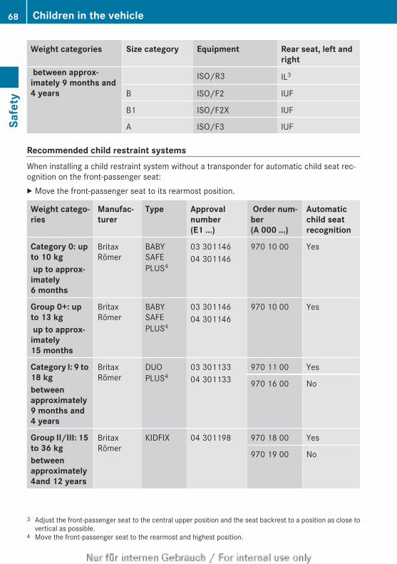
Weight categories Size category Equipment Rear seat, left andright
between approx-imately 9 months and 4 years
ISO/R3 IL3
B ISO/F2 IUF
B1 ISO/F2X IUF
A ISO/F3 IUF
Recommended child restraint systemsWhen installing a child restraint system without a transponder for automatic child seat rec-ognition on the front-passenger seat:X Move the front-passenger seat to its rearmost position.
Weight catego-ries
Manufac-turer
Type Approval number (E1 ...)
Order num-ber(A 000 ...)
Automatic child seat recognition
Category 0: up to 10 kg up to approx-imately 6 months
BritaxRömer
BABYSAFEPLUS4
03 30114604 301146
970 10 00 Yes
Group 0+: up to 13 kg up to approx-imately 15 months
BritaxRömer
BABYSAFEPLUS4
03 30114604 301146
970 10 00 Yes
Category I: 9 to 18 kgbetween approximately 9 months and 4 years
BritaxRömer
DUOPLUS4
03 30113304 301133
970 11 00 Yes
970 16 00 No
Group II/III: 15 to 36 kgbetween approximately 4and 12 years
BritaxRömer
KIDFIX 04 301198 970 18 00 Yes
970 19 00 No
3 Adjust the front-passenger seat to the central upper position and the seat backrest to a position as close tovertical as possible.
4 Move the front-passenger seat to the rearmost and highest position.
68 Children in the vehicleSa
fety
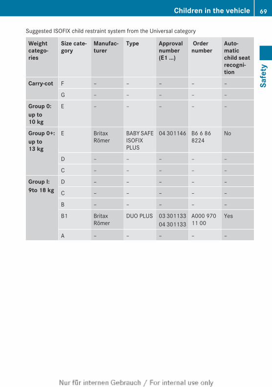
Suggested ISOFIX child restraint system from the Universal category
Weight catego-ries
Size cate-gory
Manufac-turer
Type Approval number(E1 ...)
Order number
Auto-matic child seat recogni-tion
Carry-cot F – – – – –
G – – – – –
Group 0:up to 10 kg
E – – – – –
Group 0+:up to 13 kg
E BritaxRömer
BABY SAFEISOFIXPLUS
04 301146 B6 6 868224
No
D – – – – –
C – – – – –
Group I:9to 18 kg
D – – – – –
C – – – – –
B – – – – –
B1 BritaxRömer
DUO PLUS 03 30113304 301133
A000 97011 00
Yes
A – – – – –
Children in the vehicle 69
Safe
ty
Z
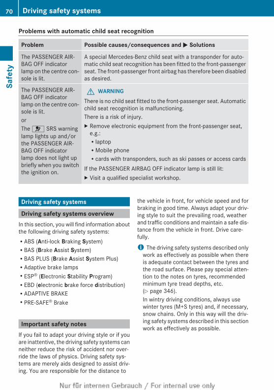
Problems with automatic child seat recognition
Problem Possible causes/consequences and M Solutions
The PASSENGER AIR-BAG OFF indicatorlamp on the centre con-sole is lit.
A special Mercedes-Benz child seat with a transponder for auto-matic child seat recognition has been fitted to the front-passengerseat. The front-passenger front airbag has therefore been disabledas desired.
The PASSENGER AIR-BAG OFF indicatorlamp on the centre con-sole is lit.orThe 6 SRS warninglamp lights up and/orthe PASSENGER AIR-BAG OFF indicatorlamp does not light upbriefly when you switchthe ignition on.
G WARNINGThere is no child seat fitted to the front-passenger seat. Automaticchild seat recognition is malfunctioning.There is a risk of injury.X Remove electronic equipment from the front-passenger seat,
e.g.:RlaptopRMobile phoneRcards with transponders, such as ski passes or access cards
If the PASSENGER AIRBAG OFF indicator lamp is still lit:X Visit a qualified specialist workshop.
Driving safety systems
Driving safety systems overviewIn this section, you will find information aboutthe following driving safety systems:RABS (Anti-lock Braking System)RBAS (Brake Assist System)RBAS PLUS (Brake Assist System Plus)RAdaptive brake lampsRESP® (Electronic Stability Program)REBD (electronic brake force distribution)RADAPTIVE BRAKERPRE-SAFE® Brake
Important safety notesIf you fail to adapt your driving style or if youare inattentive, the driving safety systems canneither reduce the risk of accident nor over-ride the laws of physics. Driving safety sys-tems are merely aids designed to assist driv-ing. You are responsible for the distance to
the vehicle in front, for vehicle speed and forbraking in good time. Always adapt your driv-ing style to suit the prevailing road, weatherand traffic conditions and maintain a safe dis-tance from the vehicle in front. Drive care-fully.
i The driving safety systems described onlywork as effectively as possible when thereis adequate contact between the tyres andthe road surface. Please pay special atten-tion to the notes on tyres, recommendedminimum tyre tread depths, etc.(Y page 346).In wintry driving conditions, always usewinter tyres (M+S tyres) and, if necessary,snow chains. Only in this way will the driv-ing safety systems described in this sectionwork as effectively as possible.
70 Driving safety systemsSa
fety
ABS (Anti-lock Braking System)
General notesABS regulates brake pressure in such a waythat the wheels do not lock when you brake.This allows you to continue steering the vehi-cle when braking.The yellow ! ABS warning lamp in theinstrument cluster lights up when the ignitionis switched on. It goes out when the engine isrunning.
Important safety notesi Observe the "Important safety notes" sec-
tion (Y page 70).
G WARNINGIf ABS is faulty, the wheels could lock whenbraking. The steerability and braking charac-teristics may be severely impaired. Addition-ally, further driving safety systems are deac-tivated. There is an increased danger of skid-ding and accidents.Drive on carefully. Have ABS checked imme-diately at a qualified specialist workshop.
If ABS is malfunctioning, other systems,including driving safety systems, will alsobecome inoperative. Observe the informationon the ABS warning lamp (Y page 282) anddisplay messages which may be shown in theinstrument cluster (Y page 242) or(Y page 247).ABS works from a speed of about8 km/hupwards, regardless of road-surfaceconditions. ABS works on slippery surfaces,even when you only brake gently.
BrakingX If ABS intervenes: continue to depress the
brake pedal with force until the braking sit-uation is over.
X To make a full brake application:depress the brake pedal with full force.
If ABS intervenes when braking, you will feela pulsing in the brake pedal.The pulsating brake pedal can be an indica-tion of hazardous road conditions, and func-tions as a reminder to take extra care whiledriving.
BAS (Brake Assist)
General notesBAS operates in emergency braking situa-tions. If you depress the brake pedal quickly,BAS automatically boosts the braking force,thus shortening the stopping distance.
Important safety notesi Observe the "Important safety notes" sec-
tion (Y page 70).
G WARNINGIf BAS is malfunctioning, the braking distancein an emergency braking situation isincreased. There is a risk of accident.In an emergency braking situation, depressthe brake pedal with full force. ABS preventsthe wheels from locking.
BrakingX Keep the brake pedal depressed firmly until
the emergency braking situation is over.ABS prevents the wheels from locking.
The brakes will function as usual once yourelease the brake pedal. BAS is deactivated.
BAS PLUS (Brake Assist System Plus)
General notesi Observe the "Important safety notes" sec-
tion (Y page 70).BAS PLUS is only available on vehicles withDISTRONIC PLUS.For BAS PLUS to assist you, the radar sensorsystem must be operational.
Driving safety systems 71
Safe
ty
Z
With the aid of the radar sensor system, BASPLUS can detect obstacles that are in thepath of your vehicle for an extended period oftime.If the radar sensor system is malfunctioning,BAS PLUS will not be available. The brakesystem is still available with complete brakeboosting effect and BAS.BAS PLUS can help you to minimise the riskof a collision with a vehicle or reduce theeffects of such a collision. If BAS PLUSdetects a danger of collision, you are assistedwhen braking.
Important safety notes
G WARNINGBAS PLUS cannot always clearly identifyobjects and complex traffic situations.In such cases, BAS PLUS may:Rintervene unnecessarilyRnot interveneThere is a risk of an accident.Always pay careful attention to the traffic sit-uation and be ready to brake. Terminate theintervention in a non-critical driving situation.
G WARNINGBAS PLUS does not react:Rto people or animalsRto oncoming vehiclesRto crossing trafficRwhen corneringAs a result, BAS PLUS may not intervene in allcritical situations. There is a risk of an acci-dent.Always pay careful attention to the traffic sit-uation and be ready to brake.
In the event of snowfall or heavy rain, recog-nition can be impaired.
Recognition by the radar sensor system isalso impaired in the event of:Rdirt on the sensors or the sensors are
obscuredRinterference by other radar sourcesRstrong radar reflections, for example, in
multi-storey car parksRa narrow vehicle travelling in front, e.g. a
motorcycleRa vehicle travelling in front on a different
lineFollowing damage to the front end of the vehi-cle, have the radar sensor settings and oper-ation checked at a qualified specialist work-shop. This also applies to collisions at slowspeeds where there is no visible damage tothe front of the vehicle.
FunctionTo avoid a collision, BAS PLUS calculates thebrake force necessary if:Ryou approach an obstacle, andRBAS PLUS has detected a risk of collisionWhen driving at a speed under 30 km/h:if you depress the brake pedal, BAS PLUS isactivated. Braking assistance from BAS PLUSis carried out at the last possible moment.When driving at a speed above 30 km/h:if you depress the brake pedal sharply, BASPLUS automatically increases the brake pres-sure to a degree suited to the traffic situation.BAS PLUS provides braking assistance in haz-ardous situations with vehicles in front withina speed range between 7 km/h and250 km/h.At speeds of up to approximately 70 km/h,BAS PLUS can also detect stationary objects.Examples of stationary objects are stoppedor parked vehicles.
i If BAS PLUS demands particularly highbraking force, preventative passenger pro-tection measures (PRE-SAFE®) are activa-ted simultaneously.
72 Driving safety systemsSa
fety
X Keep the brake pedal depressed until theemergency braking situation is over.ABS prevents the wheels from locking.
BAS PLUS is deactivated and the brakes func-tion as usual again, if:Ryou release the brake pedalRthere is no longer a risk of collisionRno obstacle is detected in front of your
vehicle
Adaptive brake lampsi Adaptive brake lamps are only available in
certain countries.If you brake sharply from a speed of morethan 50 km/h or if braking is assisted by BASor BAS PLUS, the brake lamps flash rapidly.In this way, traffic travelling behind you iswarned in an even more noticeable manner.If you brake sharply from a speed of morethan 70 km/h to a standstill, the hazard warn-ing lamps are activated automatically. If thebrakes are applied again, the brake lampslight up continuously. The hazard warninglamps switch off automatically if you travelfaster than 10 km/h. You can also switch offthe hazard warning lamps using the hazardwarning button (Y page 121).
ESP® (Electronic Stability Program)
General notesi Observe the "Important safety notes" sec-
tion (Y page 70).
ESP® monitors driving stability and traction,i.e. power transmission between the tyresand the road surface.If ESP® detects that the vehicle is deviatingfrom the direction desired by the driver, oneor more wheels are braked to stabilise thevehicle. The engine output is also modified tokeep the vehicle on the desired course withinphysical limits. ESP® assists the driver when
pulling away on wet or slippery roads. ESP®
can also stabilise the vehicle during braking.
ETS/4ETS (Electronic Traction System)i Observe the "Important safety notes" sec-
tion (Y page 70).
ETS/4ETS traction control is part of ESP®.Traction control brakes the drive wheels indi-vidually if they spin. This enables you to pullaway and accelerate on slippery surfaces, forexample if the road surface is slippery on oneside. In addition, more drive torque is trans-ferred to the wheel or wheels with traction.Traction control remains active if you deacti-vate ESP®.
Important safety notesi Observe the "Important safety notes" sec-
tion (Y page 70).
G WARNINGIf ESP® is malfunctioning, ESP® is unable tostabilise the vehicle. In addition, other drivingsafety systems are switched off. This increa-ses the risk of skidding and an accident.Drive on carefully. Have ESP® checked at aqualified specialist workshop.
! When testing the electric parking brakeon a braking dynamometer, switch off theignition. Application of the brakes byESP® may otherwise destroy the brake sys-tem.
When towing your vehicle with the rear axleraised, observe the notes onESP®(Y page 341).ESP® is deactivated if the å warning lampin the instrument cluster lights up continu-ously when the engine is running.If the ÷ warning lamp and the å warn-ing lamp are lit continuously, ESP® is notavailable due to a malfunction.Observe the information on warning lamps(Y page 284) and display messages which
Driving safety systems 73
Safe
ty
Z
may be shown in the instrument cluster(Y page 242) or (Y page 247).
i Only use wheels with the recommendedtyre sizes. Only then will ESP® functionproperly.
Characteristics of ESP
General notesIf the ÷ ESP warning lamp goes out beforebeginning the journey, ESP® is automaticallyactive.If ESP® intervenes, the ÷ ESP® warninglamp flashes in the instrument cluster.If ESP® intervenes:X Do not deactivate ESP® under any circum-
stances.X When pulling away, only depress the accel-
erator pedal as far as is necessary.X Adapt your driving style to suit the prevail-
ing road and weather conditions.
ECO start/stop functionThe ECO start/stop function switches theengine off automatically if the vehicle stopsmoving. When pulling away again, the enginestarts automatically. ESP® remains in its pre-viously selected status. Example: if ESP®
was deactivated before the engine wasswitched off, ESP® remains deactivated whenthe engine is switched on again.
Deactivating/activating ESP® (exceptAMG vehicles)
Important safety notesi Observe the "Important safety notes" sec-
tion (Y page 70).You can select between the following sta-tuses of ESP:RESP® is activated.RESP® is deactivated.
G WARNINGIf you deactivate ESP®, ESP® no longer sta-bilises the vehicle. There is an increased riskof skidding and an accident.Only deactivate ESP® in the situations descri-bed in the following.
It may be best to deactivate ESP® in the fol-lowing situations:Rwhen using snow chainsRin deep snowRon sand or gravel
i Activate ESP® as soon as the situationsdescribed above no longer apply. ESP® willotherwise not be able to stabilise the vehi-cle if the vehicle starts to skid or a wheelstarts to spin.
Deactivating/activating ESP®
You can activate and deactivate ESP® usingthe on-board computer.You cannot activate and deactivate ESP® onvehicles with a 4-button multifunction steer-ing wheel.X To deactivate:(Y page 228).
The å ESP® OFF warning lamp in theinstrument cluster lights up.
X To activate:(Y page 228).The å ESP® OFF warning lamp in theinstrument cluster goes out.
Characteristics when ESP® is deactivatedIf ESP® is deactivated and one or more wheelsstart to spin, the ÷ ESP® warning lamp inthe instrument cluster flashes. In such situa-tions, ESP® will not stabilise the vehicle.If you deactivate ESP®:RESP® no longer improves driving stability.Rengine torque is no longer limited and the
drive wheels are able to spin.The spinning of the wheels results in a cut-ting action for better traction on loose sur-faces.
74 Driving safety systemsSa
fety
Rtraction control is still activated.RESP® still provides support when you
brake.
Deactivating/activating ESP® (AMGvehicles)
Important safety notesYou can select between the following sta-tuses of ESP:RESP® is activated.RSPORT handling mode is activated.RESP® is deactivated.
G WARNINGWhen SPORT handling mode is activated,there is a greater risk of skidding and acci-dents.Only activate SPORT handling mode in the sit-uations described in the following.
G WARNINGIf you deactivate ESP®, ESP® no longer sta-bilises the vehicle. There is an increased riskof skidding and an accident.Only deactivate ESP® in the situations descri-bed in the following.
In the following situations, it may be better toactivate SPORT handling mode or deactivateESP®:Rwhen using snow chainsRin deep snowRon sand or gravelRon specially designated roads when the
vehicle's own oversteering and understeer-ing characteristics are desired
Driving in SPORT handling mode or withoutESP® requires an extremely qualified andexperienced driver.
i Activate ESP® as soon as the situationsdescribed above no longer apply. ESP® willotherwise not be able to stabilise the vehi-
cle if the vehicle starts to skid or a wheelstarts to spin.
Deactivating/activating ESP®
X To activate SPORT handling mode:briefly press button :.The M handling mode warning lamp inthe instrument cluster lights up. TheSPORT handling mode message appearsin the multifunction display.
X To deactivate SPORT handling mode:briefly press button :.The M handling mode warning lamp inthe instrument cluster goes out.
X To deactivate ESP®: press button : untilthe å ESP® OFF warning lamp lights upin the instrument cluster.The ÷OFF message appears in the mul-tifunction display.
X To activate ESP®: briefly press button :.The å ESP® OFF warning lamp in theinstrument cluster goes out. The ÷ESP®ON message appears in the multifunc-tion display.
Characteristics of activated SPORT han-dling modeIf SPORT handling mode is activated and oneor more wheels start to spin, the ÷ ESP®
warning lamp in the instrument clusterflashes. ESP® only stabilises the vehicle to alimited degree.
Driving safety systems 75
Safe
ty
Z
When SPORT handling mode is activated:RESP® only improves driving stability to a
limited degree.Rtraction control is still activated.Rengine torque is restricted to a limited
degree and the drive wheels are able tospin.The spinning of the wheels results in a cut-ting action for better traction on loose sur-faces.RESP® still provides support when you
brake.
Characteristics when ESP® is deactivatedIf ESP® is deactivated and one or more wheelsstart to spin, the ÷ ESP® warning lamp inthe instrument cluster does not flash. In suchsituations, ESP® will not stabilise the vehicle.If you deactivate ESP®:RESP® no longer improves driving stability.Rengine torque is restricted to a limited
degree and the drive wheels are able tospin.The spinning of the wheels results in a cut-ting action for better traction on loose sur-faces.Rtraction control is still activated.RPRE-SAFE® is no longer available; nor is it
activated if you brake firmly with assis-tance from ESP®.RPRE-SAFE® Brake is no longer available; it
is also not activated if you brake firmly withassistance from ESP®.RESP® still provides support when you
brake.
ESP® trailer stabilisationESP® trailer stabilisation is not available inAMG vehicles.
G WARNINGIf road and weather conditions are poor,trailer stabilisation will not be able to prevent
the vehicle/trailer combination from swerv-ing. Trailers with a high centre of gravity cantip over before ESP® can detect this. There isa risk of an accident.Always adapt your driving style to the prevail-ing road and weather conditions.
If your vehicle/trailer combination begins tolurch, you can only stabilise the vehicle/trailer combination by depressing the brakefirmly.In this situation, ESP® assists you and candetect if the vehicle/trailer combinationbegins to lurch. ESP® slows the vehicle downby braking and limiting the engine output untilthe vehicle/trailer combination has stabi-lised.Trailer stabilisation is active above speeds ofabout 65 km/h.Trailer stabilisation does not work if ESP® isdeactivated or disabled because of a mal-function.
EBD (electronic brake force distribu-tion)
General notesEBD monitors and controls the brake pres-sure on the rear wheels to improve drivingstability while braking.
Important safety notesi Observe the "Important safety notes" sec-
tion (Y page 70).
G WARNINGIf EBD has malfunctioned, the rear wheels canstill lock, e.g. under full braking. This increa-ses the risk of skidding and an accident.You should therefore adapt your driving styleto the different handling characteristics. Havethe brake system checked at a qualified spe-cialist workshop.
76 Driving safety systemsSa
fety
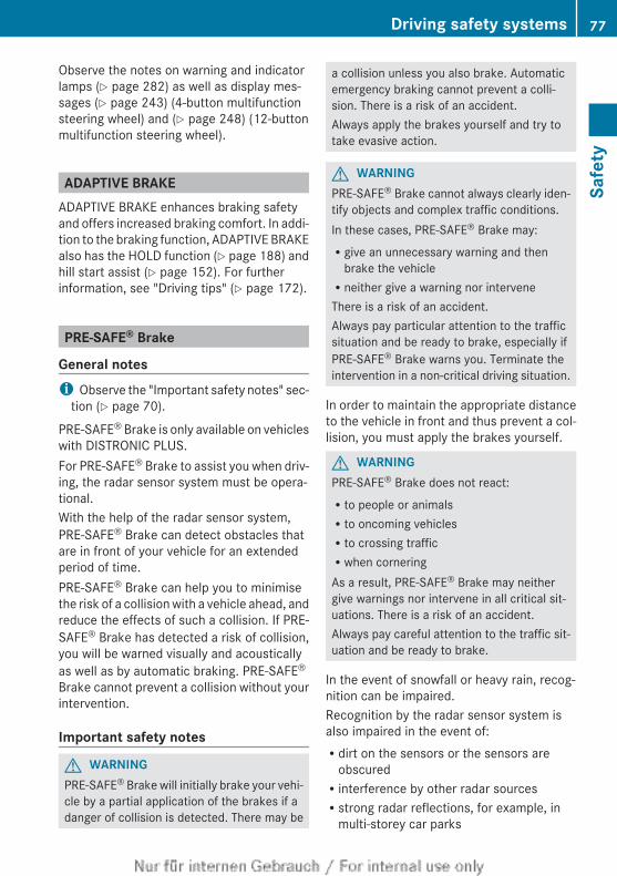
Observe the notes on warning and indicatorlamps (Y page 282) as well as display mes-sages (Y page 243) (4-button multifunctionsteering wheel) and (Y page 248) (12-buttonmultifunction steering wheel).
ADAPTIVE BRAKEADAPTIVE BRAKE enhances braking safetyand offers increased braking comfort. In addi-tion to the braking function, ADAPTIVE BRAKEalso has the HOLD function (Y page 188) andhill start assist (Y page 152). For furtherinformation, see "Driving tips" (Y page 172).
PRE-SAFE® Brake
General notesi Observe the "Important safety notes" sec-
tion (Y page 70).
PRE-SAFE® Brake is only available on vehicleswith DISTRONIC PLUS.For PRE-SAFE® Brake to assist you when driv-ing, the radar sensor system must be opera-tional.With the help of the radar sensor system,PRE-SAFE® Brake can detect obstacles thatare in front of your vehicle for an extendedperiod of time.PRE-SAFE® Brake can help you to minimisethe risk of a collision with a vehicle ahead, andreduce the effects of such a collision. If PRE-SAFE® Brake has detected a risk of collision,you will be warned visually and acousticallyas well as by automatic braking. PRE-SAFE®
Brake cannot prevent a collision without yourintervention.
Important safety notes
G WARNINGPRE-SAFE® Brake will initially brake your vehi-cle by a partial application of the brakes if adanger of collision is detected. There may be
a collision unless you also brake. Automaticemergency braking cannot prevent a colli-sion. There is a risk of an accident.Always apply the brakes yourself and try totake evasive action.
G WARNINGPRE-SAFE® Brake cannot always clearly iden-tify objects and complex traffic conditions.In these cases, PRE-SAFE® Brake may:Rgive an unnecessary warning and then
brake the vehicleRneither give a warning nor interveneThere is a risk of an accident.Always pay particular attention to the trafficsituation and be ready to brake, especially ifPRE-SAFE® Brake warns you. Terminate theintervention in a non-critical driving situation.
In order to maintain the appropriate distanceto the vehicle in front and thus prevent a col-lision, you must apply the brakes yourself.
G WARNINGPRE-SAFE® Brake does not react:Rto people or animalsRto oncoming vehiclesRto crossing trafficRwhen corneringAs a result, PRE-SAFE® Brake may neithergive warnings nor intervene in all critical sit-uations. There is a risk of an accident.Always pay careful attention to the traffic sit-uation and be ready to brake.
In the event of snowfall or heavy rain, recog-nition can be impaired.Recognition by the radar sensor system isalso impaired in the event of:Rdirt on the sensors or the sensors are
obscuredRinterference by other radar sourcesRstrong radar reflections, for example, in
multi-storey car parks
Driving safety systems 77
Safe
ty
Z
Ra narrow vehicle travelling in front, e.g. amotorcycleRa vehicle travelling in front on a different
lineFollowing damage to the front end of the vehi-cle, have the radar sensor settings and oper-ation checked at a qualified specialist work-shop. This also applies to collisions at slowspeeds where there is no visible damage tothe front of the vehicle.
FunctionX To activate/deactivate: activate or deac-
tivate PRE-SAFE® Brake in the on-boardcomputer (Y page 229).If the PRE-SAFE® Brake is not activated, theæ symbol appears in the multifunctiondisplay.
This function will issue a warning if:Rat a speed of around 30 km/h or more the
distance maintained to the vehicle travel-ling in front is insufficient for several sec-onds.The · distance warning lamp then lightsup in the instrument cluster.Rat a speed of approximately 7 km/h or
more, you rapidly approach a vehicle infront.An intermittent warning tone will thensound and the · distance warning lampwill light up in the instrument cluster.
X Brake immediately to defuse the situation.orX Take evasive action provided it is safe to do
so.
The PRE-SAFE® Brake function can also brakethe vehicle automatically under the followingconditions:Rthe driver and front-passenger have their
seat belts fastenedandRthe vehicle speed is between approx-
imately 7 km/h and 200 km/h
At speeds of up to approximately 70 km/hPRE-SAFE® Brake can also detect stationaryobjects. Examples of stationary objects arestopped or parked vehicles.
i If there is an increased risk of collision,preventive passenger protection measures(PRE-SAFE®) are activated.
If the risk of collision with the vehicle in frontremains and you do not brake, take evasiveaction or accelerate significantly, the vehiclemay perform automatic emergency braking,up to the point of full brake application. Auto-matic emergency braking is not performeduntil immediately prior to an imminent acci-dent.You can prevent the intervention of the PRE-SAFE® Brake at any time by:Rdepressing the accelerator pedal furtherRactivating kickdownRreleasing the brake pedalThe braking action of PRE-SAFE® Brake isended automatically if:Ryou manoeuvre to avoid the obstacleRthere is no longer any danger of a collisionRthere is no longer an obstacle detected in
front of your vehicle
Anti-theft systems
ImmobiliserThe immobiliser prevents your vehicle frombeing started without the correct key.X To activate with the key: remove the key
from the ignition lock.X To activate with KEYLESS-GO: switch the
ignition off and open the driver's door.X To deactivate: switch on the ignition.
i The immobiliser is always deactivatedwhen you start the engine.
78 Anti-theft systemsSa
fety
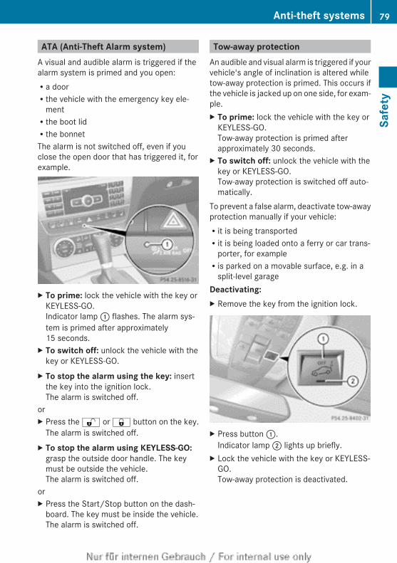
ATA (Anti-Theft Alarm system)A visual and audible alarm is triggered if thealarm system is primed and you open:Ra doorRthe vehicle with the emergency key ele-
mentRthe boot lidRthe bonnetThe alarm is not switched off, even if youclose the open door that has triggered it, forexample.
X To prime: lock the vehicle with the key orKEYLESS-GO.Indicator lamp : flashes. The alarm sys-tem is primed after approximately15 seconds.
X To switch off: unlock the vehicle with thekey or KEYLESS-GO.
X To stop the alarm using the key: insertthe key into the ignition lock.The alarm is switched off.
orX Press the % or & button on the key.
The alarm is switched off.X To stop the alarm using KEYLESS-GO:
grasp the outside door handle. The keymust be outside the vehicle.The alarm is switched off.
orX Press the Start/Stop button on the dash-
board. The key must be inside the vehicle.The alarm is switched off.
Tow-away protectionAn audible and visual alarm is triggered if yourvehicle's angle of inclination is altered whiletow-away protection is primed. This occurs ifthe vehicle is jacked up on one side, for exam-ple.X To prime: lock the vehicle with the key or
KEYLESS-GO.Tow-away protection is primed afterapproximately 30 seconds.
X To switch off: unlock the vehicle with thekey or KEYLESS-GO.Tow-away protection is switched off auto-matically.
To prevent a false alarm, deactivate tow-awayprotection manually if your vehicle:Rit is being transportedRit is being loaded onto a ferry or car trans-
porter, for exampleRis parked on a movable surface, e.g. in a
split-level garageDeactivating:X Remove the key from the ignition lock.
X Press button :.Indicator lamp ; lights up briefly.
X Lock the vehicle with the key or KEYLESS-GO.Tow-away protection is deactivated.
Anti-theft systems 79
Safe
ty
Z
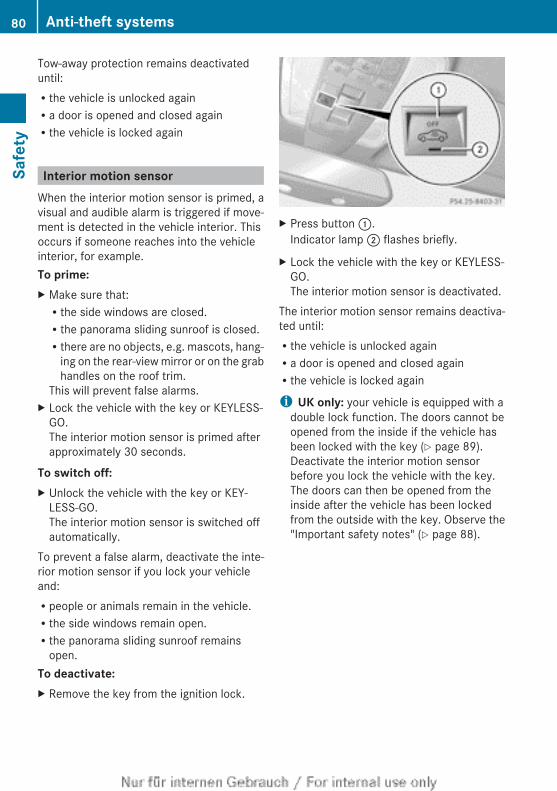
Tow-away protection remains deactivateduntil:Rthe vehicle is unlocked againRa door is opened and closed againRthe vehicle is locked again
Interior motion sensorWhen the interior motion sensor is primed, avisual and audible alarm is triggered if move-ment is detected in the vehicle interior. Thisoccurs if someone reaches into the vehicleinterior, for example.To prime:X Make sure that:Rthe side windows are closed.Rthe panorama sliding sunroof is closed.Rthere are no objects, e.g. mascots, hang-
ing on the rear-view mirror or on the grabhandles on the roof trim.
This will prevent false alarms.X Lock the vehicle with the key or KEYLESS-
GO.The interior motion sensor is primed afterapproximately 30 seconds.
To switch off:X Unlock the vehicle with the key or KEY-
LESS-GO.The interior motion sensor is switched offautomatically.
To prevent a false alarm, deactivate the inte-rior motion sensor if you lock your vehicleand:Rpeople or animals remain in the vehicle.Rthe side windows remain open.Rthe panorama sliding sunroof remains
open.To deactivate:X Remove the key from the ignition lock.
X Press button :.Indicator lamp ; flashes briefly.
X Lock the vehicle with the key or KEYLESS-GO.The interior motion sensor is deactivated.
The interior motion sensor remains deactiva-ted until:Rthe vehicle is unlocked againRa door is opened and closed againRthe vehicle is locked again
i UK only: your vehicle is equipped with adouble lock function. The doors cannot beopened from the inside if the vehicle hasbeen locked with the key (Y page 89).Deactivate the interior motion sensorbefore you lock the vehicle with the key.The doors can then be opened from theinside after the vehicle has been lockedfrom the outside with the key. Observe the"Important safety notes" (Y page 88).
80 Anti-theft systemsSa
fety
Useful information .............................. 82Key ....................................................... 82Doors .................................................... 88Boot ...................................................... 91Side windows ...................................... 94Sliding sunroof .................................... 98
81
Open
ing
and
clos
ing
Useful information
i This Owner's Manual describes all mod-els, series and optional equipment for yourvehicle that were available at the time ofgoing to press. National variations are pos-sible. Note that your vehicle may not beequipped with all of the functions descri-bed. This is also the case for systems andfunctions relevant to safety.
i Read the information on qualified special-ist workshops: (Y page 28).
Key
Important safety notesUnited Kingdom only:
G WARNINGWhen the double locks are activated, thedoors can no longer be opened from theinside. People in the vehicle can no longer getout, e.g. in hazardous situations. There is arisk of injury.Therefore, do not leave any people unsuper-vised in the vehicle, particularly children, eld-erly people or people in need of special assis-tance. Do not activate the double lock whenpeople are in the vehicle.
If the vehicle has been locked from the out-side, the double lock function is activated asstandard. It is then not possible to open thedoors from inside the vehicle. You can deac-tivate the double lock function by deactivat-ing the interior motion sensor (Y page 80).The doors can then be opened from the insideafter the vehicle has been locked from theoutside. The anti-theft alarm system is trig-gered if the door is opened from the inside.Switch off the alarm (Y page 79).All countries:
G WARNINGIf children are left unsupervised in the vehicle,they could:Ropen the doors, thus endangering other
people or road users.Rget out and disrupt traffic.Roperate the vehicle's equipment.Additionally, children could set the vehicle inmotion if, for example, they:Rrelease the parking brake.Rshift the automatic transmission out of
parking position P.Rshift the manual transmission into neutral.Rstart the engine.There is a risk of an accident and injury.When leaving the vehicle, always take the keywith you and lock the vehicle. Never leavechildren or animals unattended in the vehicle.Always keep the key out of reach of children.
G WARNINGIf persons (particularly children) are exposedto heat or cold for a prolonged period, thereis a risk of serious or even fatal injuries. Neverleave persons (particularly children) unatten-ded in the vehicle.
G WARNINGIf you attach heavy or large objects to the key,the key could be unintentionally turned in theignition lock. This could cause the engine tobe switched off. There is a risk of an accident.Do not attach any heavy or large objects tothe key. Remove any bulky keyrings beforeinserting the key into the ignition lock.
! Keep the key away from strong magneticfields. Otherwise, the remote control func-tion could be affected.
82 KeyOp
enin
g an
d cl
osin
g
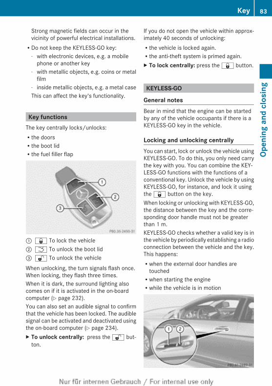
Strong magnetic fields can occur in thevicinity of powerful electrical installations.RDo not keep the KEYLESS-GO key:
- with electronic devices, e.g. a mobilephone or another key
- with metallic objects, e.g. coins or metalfilm
- inside metallic objects, e.g. a metal caseThis can affect the key's functionality.
Key functionsThe key centrally locks/unlocks:Rthe doorsRthe boot lidRthe fuel filler flap
: & To lock the vehicle; F To unlock the boot lid= % To unlock the vehicle
When unlocking, the turn signals flash once.When locking, they flash three times.When it is dark, the surround lighting alsocomes on if it is activated in the on-boardcomputer (Y page 232).You can also set an audible signal to confirmthat the vehicle has been locked. The audiblesignal can be activated and deactivated usingthe on-board computer (Y page 234).X To unlock centrally: press the % but-
ton.
If you do not open the vehicle within approx-imately 40 seconds of unlocking:Rthe vehicle is locked again.Rthe anti-theft system is primed again.X To lock centrally: press the & button.
KEYLESS-GO
General notesBear in mind that the engine can be startedby any of the vehicle occupants if there is aKEYLESS-GO key in the vehicle.
Locking and unlocking centrallyYou can start, lock or unlock the vehicle usingKEYLESS-GO. To do this, you only need carrythe key with you. You can combine the KEY-LESS-GO functions with the functions of aconventional key. Unlock the vehicle by usingKEYLESS-GO, for instance, and lock it usingthe & button on the key.When locking or unlocking with KEYLESS-GO,the distance between the key and the corre-sponding door handle must not be greaterthan 1 m.KEYLESS-GO checks whether a valid key is inthe vehicle by periodically establishing a radioconnection between the vehicle and the key.This happens:Rwhen the external door handles are
touchedRwhen starting the engineRwhile the vehicle is in motion
Key 83
Open
ing
and
clos
ing
Z
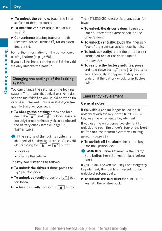
X To unlock the vehicle: touch the innersurface of the door handle.
X To lock the vehicle: touch sensor sur-face :.
X Convenience closing feature: touchrecessed sensor surface ; for an exten-ded period.
For further information on the convenienceclosing feature (Y page 96).If you pull the handle on the boot lid, the vehi-cle only unlocks the boot lid.
Changing the settings of the lockingsystem
You can change the settings of the lockingsystem. This means that only the driver's doorand the fuel filler flap are unlocked when thevehicle is unlocked. This is useful if you fre-quently travel on your own.X To change the setting: press and hold
down the % and & buttons simulta-neously for approximately six seconds untilthe battery check lamp (Y page 85)flashes twice.
i If the setting of the locking system ischanged within the signal range of the vehi-cle, pressing the & or % button:Rlocks orRunlocks the vehicle
The key now functions as follows:X To unlock the driver's door: press the% button once.
X To unlock centrally: press the % but-ton twice.
X To lock centrally: press the & button.
The KEYLESS-GO function is changed as fol-lows:X To unlock the driver's door: touch the
inner surface of the door handle on thedriver's door.
X To unlock centrally: touch the inner sur-face of the front-passenger door handle.
X To lock centrally: touch the outer sensorsurface on one of the door handles(Y page 83).
X To restore the factory settings: pressand hold down the % and & buttonssimultaneously for approximately six sec-onds until the battery check lamp flashestwice.
Emergency key element
General notesIf the vehicle can no longer be locked orunlocked with the key or the KEYLESS-GOkey, use the emergency key element.If you use the emergency key element tounlock and open the driver's door or the bootlid, the anti-theft alarm system will be trig-gered (Y page 79).X To switch off the alarm: insert the key
into the ignition lock.i With KEYLESS-GO: remove the Start/
Stop button from the ignition lock before-hand.
If you unlock the vehicle using the emergencykey element, the fuel filler flap will not beunlocked automatically.X To unlock the fuel filler flap: insert the
key into the ignition lock.
84 KeyOp
enin
g an
d cl
osin
g
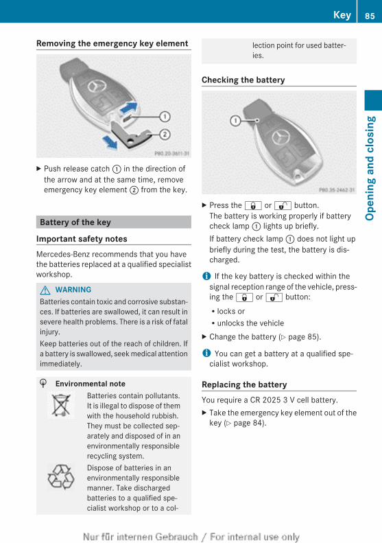
Removing the emergency key element
X Push release catch : in the direction ofthe arrow and at the same time, removeemergency key element ; from the key.
Battery of the key
Important safety notesMercedes-Benz recommends that you havethe batteries replaced at a qualified specialistworkshop.
G WARNINGBatteries contain toxic and corrosive substan-ces. If batteries are swallowed, it can result insevere health problems. There is a risk of fatalinjury.Keep batteries out of the reach of children. Ifa battery is swallowed, seek medical attentionimmediately.
H Environmental noteBatteries contain pollutants.It is illegal to dispose of themwith the household rubbish.They must be collected sep-arately and disposed of in anenvironmentally responsiblerecycling system.Dispose of batteries in anenvironmentally responsiblemanner. Take dischargedbatteries to a qualified spe-cialist workshop or to a col-
lection point for used batter-ies.
Checking the battery
X Press the & or % button.The battery is working properly if batterycheck lamp : lights up briefly.If battery check lamp : does not light upbriefly during the test, the battery is dis-charged.
i If the key battery is checked within thesignal reception range of the vehicle, press-ing the & or % button:Rlocks orRunlocks the vehicle
X Change the battery (Y page 85).
i You can get a battery at a qualified spe-cialist workshop.
Replacing the batteryYou require a CR 2025 3 V cell battery.X Take the emergency key element out of the
key (Y page 84).
Key 85
Open
ing
and
clos
ing
Z
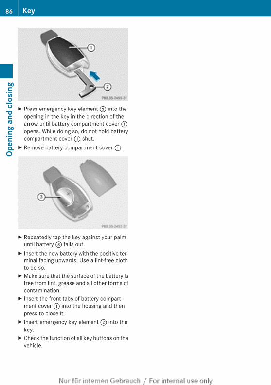
X Press emergency key element ; into theopening in the key in the direction of thearrow until battery compartment cover :opens. While doing so, do not hold batterycompartment cover : shut.
X Remove battery compartment cover :.
X Repeatedly tap the key against your palmuntil battery = falls out.
X Insert the new battery with the positive ter-minal facing upwards. Use a lint-free clothto do so.
X Make sure that the surface of the battery isfree from lint, grease and all other forms ofcontamination.
X Insert the front tabs of battery compart-ment cover : into the housing and thenpress to close it.
X Insert emergency key element ; into thekey.
X Check the function of all key buttons on thevehicle.
86 KeyOp
enin
g an
d cl
osin
g
Problems with the key
Problem Possible causes/consequences and M Solutions
You cannot lock orunlock the vehicleusing the key.
The key battery is discharged or nearly discharged.X Try again to lock/unlock the vehicle using the remote control
function of the key. Point the tip of the key at the driver's doorhandle from close range and press the % / & button.
If this does not work:X Check the key battery (Y page 85) and replace it if necessary
(Y page 85).X Lock (Y page 90) or unlock (Y page 91) the vehicle using
the emergency key element.
The key is faulty.X Lock (Y page 90) or unlock (Y page 91) the vehicle using
the emergency key element.X Have the key checked at a qualified specialist workshop.
You can no longer lockor unlock the vehicleusing KEYLESS-GO.
There is interference from a powerful source of radio waves.X Lock/unlock the vehicle using the remote control function of
the key. Point the tip of the key at the driver's door handle fromclose range and press the % / & button.
There is a fault with KEYLESS-GO.X Lock/unlock the vehicle using the remote control function of
the key. Point the tip of the key at the driver's door handle fromclose range and press the % / & button.
X Have KEYLESS-GO checked at a qualified specialist workshop.If this does not work:X Check the key battery (Y page 85) and replace it if necessary
(Y page 85).X Lock (Y page 90) or unlock (Y page 91) the vehicle using
the emergency key element.
You have lost a key. X Have the key deactivated at a qualified specialist workshop.X Report the loss immediately to the vehicle insurers.X If necessary, have the locks changed as well.
You have lost the emer-gency key element.
X Report the loss immediately to the vehicle insurers.X If necessary, have the locks changed as well.
Key 87
Open
ing
and
clos
ing
Z
Problem Possible causes/consequences and M Solutions
The engine cannot bestarted using the key.
The on-board voltage is too low.X Switch off non-essential consumers, e.g. seat heating or interior
lighting, and try to start the engine again.If this does not work:X Check the starter battery and charge it if necessary
(Y page 334).orX Jump-start the vehicle (Y page 338).orX Consult a qualified specialist workshop.
The engine cannot bestarted using the key.
The steering lock is mechanically blocked.X Remove the key and reinsert it into the ignition lock. While doing
this, turn the steering wheel in both directions.
The engine cannot bestarted using KEYLESS-GO. The key is in thevehicle.
A door is open. Therefore, the key cannot be detected as easily.X Close the door and try to start the vehicle again.
There is interference from a powerful source of radio waves.X Start your vehicle with the key in the ignition lock.
Doors
Important safety notesUnited Kingdom only:
G WARNINGWhen the double locks are activated, thedoors can no longer be opened from theinside. People in the vehicle can no longer getout, e.g. in hazardous situations. There is arisk of injury.Therefore, do not leave any people unsuper-vised in the vehicle, particularly children, eld-erly people or people in need of special assis-tance. Do not activate the double lock whenpeople are in the vehicle.
If the vehicle has been locked from the out-side, the double lock function is activated asstandard. It is then not possible to open thedoors from inside the vehicle. You can deac-tivate the double lock function by deactivat-
ing the interior motion sensor (Y page 80).The doors can then be opened from the insideafter the vehicle has been locked from theoutside. The anti-theft alarm system is trig-gered if the door is opened from the inside.Switch off the alarm (Y page 79).All countries:
G WARNINGIf children are left unsupervised in the vehicle,they could:Ropen the doors, thus endangering other
people or road users.Rget out and disrupt traffic.Roperate the vehicle's equipment.Additionally, children could set the vehicle inmotion if, for example, they:Rrelease the parking brake.Rshift the automatic transmission out of
parking position P.
88 DoorsOp
enin
g an
d cl
osin
g
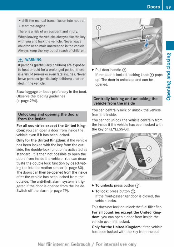
Rshift the manual transmission into neutral.Rstart the engine.There is a risk of an accident and injury.When leaving the vehicle, always take the keywith you and lock the vehicle. Never leavechildren or animals unattended in the vehicle.Always keep the key out of reach of children.
G WARNINGIf persons (particularly children) are exposedto heat or cold for a prolonged period, thereis a risk of serious or even fatal injuries. Neverleave persons (particularly children) unatten-ded in the vehicle.
Stow luggage or loads preferably in the boot.Observe the loading guidelines(Y page 294).
Unlocking and opening the doorsfrom the inside
For all countries except the United King-dom: you can open a door from inside thevehicle even if it has been locked.Only for the United Kingdom: if the vehiclehas been locked with the key from the out-side, the double-lock function is activated asstandard. It is then not possible to open thedoors from inside the vehicle. You can deac-tivate the double lock function by deactivat-ing the interior motion sensor (Y page 80).The doors can then be opened from the insideafter the vehicle has been locked from theoutside. The anti-theft alarm system is trig-gered if the door is opened from the inside.Switch off the alarm (Y page 79).
X Pull door handle ;.If the door is locked, locking knob : popsup. The door is unlocked and can beopened.
Centrally locking and unlocking thevehicle from the inside
You can centrally lock or unlock the vehiclefrom the inside.You cannot unlock the vehicle centrally fromthe inside if the vehicle has been locked withthe key or KEYLESS-GO.
X To unlock: press button :.X To lock: press button ;.
If the front-passenger door is closed, thevehicle locks.
This does not lock or unlock the fuel filler flap.For all countries except the United King-dom: you can open a door from inside thevehicle even if it locked.Only for the United Kingdom: if the vehiclehas been locked with the key from the out-
Doors 89
Open
ing
and
clos
ing
Z
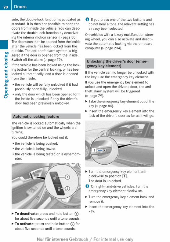
side, the double-lock function is activated asstandard. It is then not possible to open thedoors from inside the vehicle. You can deac-tivate the double lock function by deactivat-ing the interior motion sensor (Y page 80).The doors can then be opened from the insideafter the vehicle has been locked from theoutside. The anti-theft alarm system is trig-gered if the door is opened from the inside.Switch off the alarm (Y page 79).If the vehicle has been locked using the lock-ing button for the central locking, or has beenlocked automatically, and a door is openedfrom the inside:Rthe vehicle will be fully unlocked if it had
previously been fully unlockedRonly the door which has been opened form
the inside is unlocked if only the driver'sdoor had been previously unlocked
Automatic locking featureThe vehicle is locked automatically when theignition is switched on and the wheels areturning.You could therefore be locked out if:Rthe vehicle is being pushed.Rthe vehicle is being towed.Rthe vehicle is being tested on a dynamom-
eter.
X To deactivate: press and hold button :for about five seconds until a tone sounds.
X To activate: press and hold button ; forabout five seconds until a tone sounds.
i If you press one of the two buttons anddo not hear a tone, the relevant setting hasalready been selected.
On vehicles with a luxury multifunction steer-ing wheel, you can also activate and deacti-vate the automatic locking via the on-boardcomputer (Y page 234).
Unlocking the driver's door (emer-gency key element)
If the vehicle can no longer be unlocked withthe key, use the emergency key element.If you use the emergency key element tounlock and open the driver's door, the anti-theft alarm system will be triggered(Y page 79).X Take the emergency key element out of the
key (Y page 84).X Insert the emergency key element into the
lock of the driver's door as far as it will go.
X Turn the emergency key element anti-clockwise to position 1.The door is unlocked.
i On right-hand-drive vehicles, turn theemergency key element clockwise.
X Turn the emergency key element back andremove it.
X Insert the emergency key element into thekey.
90 DoorsOp
enin
g an
d cl
osin
g
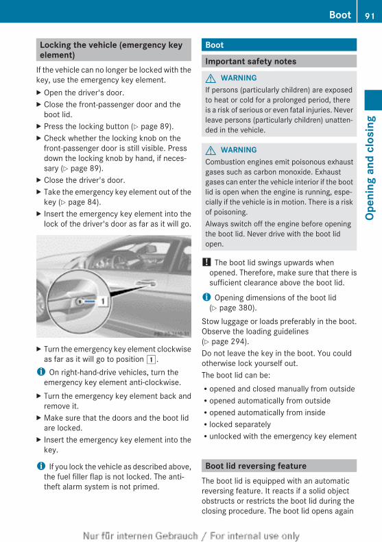
Locking the vehicle (emergency keyelement)
If the vehicle can no longer be locked with thekey, use the emergency key element.X Open the driver's door.X Close the front-passenger door and the
boot lid.X Press the locking button (Y page 89).X Check whether the locking knob on the
front-passenger door is still visible. Pressdown the locking knob by hand, if neces-sary (Y page 89).
X Close the driver's door.X Take the emergency key element out of the
key (Y page 84).X Insert the emergency key element into the
lock of the driver's door as far as it will go.
X Turn the emergency key element clockwiseas far as it will go to position 1.
i On right-hand-drive vehicles, turn theemergency key element anti-clockwise.
X Turn the emergency key element back andremove it.
X Make sure that the doors and the boot lidare locked.
X Insert the emergency key element into thekey.
i If you lock the vehicle as described above,the fuel filler flap is not locked. The anti-theft alarm system is not primed.
Boot
Important safety notes
G WARNINGIf persons (particularly children) are exposedto heat or cold for a prolonged period, thereis a risk of serious or even fatal injuries. Neverleave persons (particularly children) unatten-ded in the vehicle.
G WARNINGCombustion engines emit poisonous exhaustgases such as carbon monoxide. Exhaustgases can enter the vehicle interior if the bootlid is open when the engine is running, espe-cially if the vehicle is in motion. There is a riskof poisoning.Always switch off the engine before openingthe boot lid. Never drive with the boot lidopen.
! The boot lid swings upwards whenopened. Therefore, make sure that there issufficient clearance above the boot lid.
i Opening dimensions of the boot lid(Y page 380).
Stow luggage or loads preferably in the boot.Observe the loading guidelines(Y page 294).Do not leave the key in the boot. You couldotherwise lock yourself out.The boot lid can be:Ropened and closed manually from outsideRopened automatically from outsideRopened automatically from insideRlocked separatelyRunlocked with the emergency key element
Boot lid reversing featureThe boot lid is equipped with an automaticreversing feature. It reacts if a solid objectobstructs or restricts the boot lid during theclosing procedure. The boot lid opens again
Boot 91
Open
ing
and
clos
ing
Z
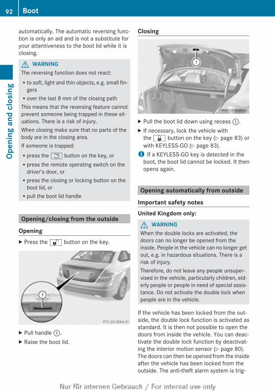
automatically. The automatic reversing func-tion is only an aid and is not a substitute foryour attentiveness to the boot lid while it isclosing.
G WARNINGThe reversing function does not react:Rto soft, light and thin objects, e.g. small fin-
gersRover the last 8 mm of the closing pathThis means that the reversing feature cannotprevent someone being trapped in these sit-uations. There is a risk of injury.When closing make sure that no parts of thebody are in the closing area.If someone is trapped:Rpress the F button on the key, orRpress the remote operating switch on the
driver's door, orRpress the closing or locking button on the
boot lid, orRpull the boot lid handle
Opening/closing from the outside
OpeningX Press the % button on the key.
X Pull handle :.X Raise the boot lid.
Closing
X Pull the boot lid down using recess :.X If necessary, lock the vehicle with
the & button on the key (Y page 83) orwith KEYLESS-GO (Y page 83).
i If a KEYLESS-GO key is detected in theboot, the boot lid cannot be locked. It thenopens again.
Opening automatically from outside
Important safety notesUnited Kingdom only:
G WARNINGWhen the double locks are activated, thedoors can no longer be opened from theinside. People in the vehicle can no longer getout, e.g. in hazardous situations. There is arisk of injury.Therefore, do not leave any people unsuper-vised in the vehicle, particularly children, eld-erly people or people in need of special assis-tance. Do not activate the double lock whenpeople are in the vehicle.
If the vehicle has been locked from the out-side, the double lock function is activated asstandard. It is then not possible to open thedoors from inside the vehicle. You can deac-tivate the double lock function by deactivat-ing the interior motion sensor (Y page 80).The doors can then be opened from the insideafter the vehicle has been locked from theoutside. The anti-theft alarm system is trig-
92 BootOp
enin
g an
d cl
osin
g
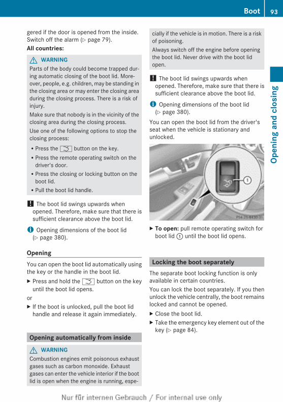
gered if the door is opened from the inside.Switch off the alarm (Y page 79).All countries:
G WARNINGParts of the body could become trapped dur-ing automatic closing of the boot lid. More-over, people, e.g. children, may be standing inthe closing area or may enter the closing areaduring the closing process. There is a risk ofinjury.Make sure that nobody is in the vicinity of theclosing area during the closing process.Use one of the following options to stop theclosing process:RPress the F button on the key.RPress the remote operating switch on the
driver's door.RPress the closing or locking button on the
boot lid.RPull the boot lid handle.
! The boot lid swings upwards whenopened. Therefore, make sure that there issufficient clearance above the boot lid.
i Opening dimensions of the boot lid(Y page 380).
OpeningYou can open the boot lid automatically usingthe key or the handle in the boot lid.X Press and hold the F button on the key
until the boot lid opens.orX If the boot is unlocked, pull the boot lid
handle and release it again immediately.
Opening automatically from inside
G WARNINGCombustion engines emit poisonous exhaustgases such as carbon monoxide. Exhaustgases can enter the vehicle interior if the bootlid is open when the engine is running, espe-
cially if the vehicle is in motion. There is a riskof poisoning.Always switch off the engine before openingthe boot lid. Never drive with the boot lidopen.
! The boot lid swings upwards whenopened. Therefore, make sure that there issufficient clearance above the boot lid.
i Opening dimensions of the boot lid(Y page 380).
You can open the boot lid from the driver'sseat when the vehicle is stationary andunlocked.
X To open: pull remote operating switch forboot lid : until the boot lid opens.
Locking the boot separatelyThe separate boot locking function is onlyavailable in certain countries.You can lock the boot separately. If you thenunlock the vehicle centrally, the boot remainslocked and cannot be opened.X Close the boot lid.X Take the emergency key element out of the
key (Y page 84).
Boot 93
Open
ing
and
clos
ing
Z
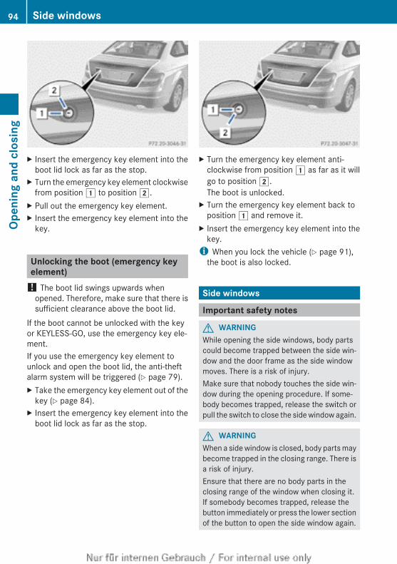
X Insert the emergency key element into theboot lid lock as far as the stop.
X Turn the emergency key element clockwisefrom position 1 to position 2.
X Pull out the emergency key element.X Insert the emergency key element into the
key.
Unlocking the boot (emergency keyelement)
! The boot lid swings upwards whenopened. Therefore, make sure that there issufficient clearance above the boot lid.
If the boot cannot be unlocked with the keyor KEYLESS-GO, use the emergency key ele-ment.If you use the emergency key element tounlock and open the boot lid, the anti-theftalarm system will be triggered (Y page 79).X Take the emergency key element out of the
key (Y page 84).X Insert the emergency key element into the
boot lid lock as far as the stop.
X Turn the emergency key element anti-clockwise from position 1 as far as it willgo to position 2.The boot is unlocked.
X Turn the emergency key element back toposition 1 and remove it.
X Insert the emergency key element into thekey.
i When you lock the vehicle (Y page 91),the boot is also locked.
Side windows
Important safety notes
G WARNINGWhile opening the side windows, body partscould become trapped between the side win-dow and the door frame as the side windowmoves. There is a risk of injury.Make sure that nobody touches the side win-dow during the opening procedure. If some-body becomes trapped, release the switch orpull the switch to close the side window again.
G WARNINGWhen a side window is closed, body parts maybecome trapped in the closing range. There isa risk of injury.Ensure that there are no body parts in theclosing range of the window when closing it.If somebody becomes trapped, release thebutton immediately or press the lower sectionof the button to open the side window again.
94 Side windowsOp
enin
g an
d cl
osin
g
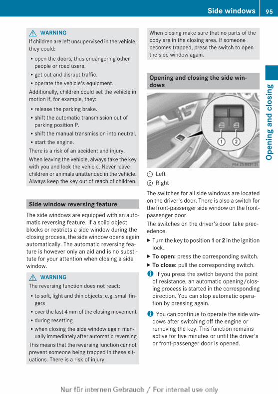
G WARNINGIf children are left unsupervised in the vehicle,they could:Ropen the doors, thus endangering other
people or road users.Rget out and disrupt traffic.Roperate the vehicle's equipment.Additionally, children could set the vehicle inmotion if, for example, they:Rrelease the parking brake.Rshift the automatic transmission out of
parking position P.Rshift the manual transmission into neutral.Rstart the engine.There is a risk of an accident and injury.When leaving the vehicle, always take the keywith you and lock the vehicle. Never leavechildren or animals unattended in the vehicle.Always keep the key out of reach of children.
Side window reversing featureThe side windows are equipped with an auto-matic reversing feature. If a solid objectblocks or restricts a side window during theclosing process, the side window opens againautomatically. The automatic reversing fea-ture is however only an aid and is no substi-tute for your attention when closing a sidewindow.
G WARNINGThe reversing function does not react:Rto soft, light and thin objects, e.g. small fin-
gersRover the last 4 mm of the closing movementRduring resettingRwhen closing the side window again man-
ually immediately after automatic reversingThis means that the reversing function cannotprevent someone being trapped in these sit-uations. There is a risk of injury.
When closing make sure that no parts of thebody are in the closing area. If someonebecomes trapped, press the switch to openthe side window again.
Opening and closing the side win-dows
: Left; Right
The switches for all side windows are locatedon the driver's door. There is also a switch forthe front-passenger side window on the front-passenger door.The switches on the driver's door take prec-edence.X Turn the key to position 1 or 2 in the ignition
lock.X To open: press the corresponding switch.X To close: pull the corresponding switch.i If you press the switch beyond the point
of resistance, an automatic opening/clos-ing process is started in the correspondingdirection. You can stop automatic opera-tion by pressing again.
i You can continue to operate the side win-dows after switching off the engine orremoving the key. This function remainsactive for five minutes or until the driver'sor front-passenger door is opened.
Side windows 95
Open
ing
and
clos
ing
Z
Convenience opening featureYou can ventilate the vehicle before you startdriving. To do this, the key is used to carry outthe following functions simultaneously:Runlock the vehicleRopen the side windowsRopen the panorama sliding sunroof and the
roller sunblindRswitch on the seat ventilation for the driv-
er's seat
i The convenience opening feature canonly be operated using the key. The keymust be close to the driver's door handle.
X Point the tip of the key at the driver's doorhandle.
X Press and hold the % button until theside windows and the panorama sunroofare in the desired position.
If the roller sunblind of the panorama slidingsunroof is closed, the roller sunblind isopened first.X Press and hold the % button again until
the panorama sliding sunroof is in thedesired position.
X To interrupt convenience opening:release the % button.
Convenience closing feature
General notesWhen you lock the vehicle, you can simulta-neously:Rclose the side windowsRclose the panorama sliding sunroofOn vehicles with a panorama sliding sunroof,you can then close the roller sunblind.
G WARNINGWhen the convenience closing feature is oper-ating, parts of the body could become trappedin the closing area of the side window and thesliding sunroof. There is a risk of injury.
Observe the complete closing procedurewhen the convenience closing feature is oper-ating. When closing make sure that no partsof the body are in the closing area.
Proceed as follows if someone is trapped:With the key:Rrelease the & button.Rpress and hold the % button until the
side windows and the sliding sunroof or thepanorama sliding sunroof open again.
With KEYLESS-GO:Rrelease the sensor surface on the door han-
dle.Rpull the door handle immediately and hold
it.The side windows and the sliding sunroofor the panorama sliding sunroof open.
Using the keyi The key must be close to the driver's door
handle.X Point the tip of the key at the driver's door
handle.X Press and hold the & button until the
side windows and the panorama slidingsunroof are fully closed.
X Make sure that all the side windows and thepanorama sliding sunroof are closed.
On vehicles with a panorama sliding sunroof:X Press and hold the & button again until
the roller sunblind of the panorama slidingsunroof closes.
X To interrupt convenience closing:release the & button.
Using KEYLESS-GOThe KEYLESS-GO key must be outside thevehicle. All the doors must be closed.
96 Side windowsOp
enin
g an
d cl
osin
g
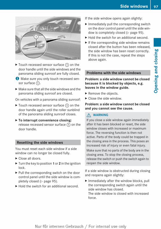
X Touch recessed sensor surface : on thedoor handle until the side windows and thepanorama sliding sunroof are fully closed.
i Make sure you only touch recessed sen-sor surface :.
X Make sure that all the side windows and thepanorama sliding sunroof are closed.
On vehicles with a panorama sliding sunroof:X Touch recessed sensor surface : on the
door handle again until the roller sunblindof the panorama sliding sunroof closes.
X To interrupt convenience closing: release recessed sensor surface : on thedoor handle.
Resetting the side windowsYou must reset each side window if a sidewindow can no longer be closed fully.X Close all doors.X Turn the key to position 1 or 2 in the ignition
lock.X Pull the corresponding switch on the door
control panel until the side window is com-pletely closed (Y page 95).
X Hold the switch for an additional second.
If the side window opens again slightly:X Immediately pull the corresponding switch
on the door control panel until the side win-dow is completely closed (Y page 95).
X Hold the switch for an additional second.X If the corresponding side window remains
closed after the button has been released,the side window has been reset correctly.If this is not the case, repeat the stepsabove again.
Problems with the side windowsProblem: a side window cannot be closed because it is blocked by objects, e.g. leaves in the window guide.X Remove the objects.X Close the side window.Problem: a side window cannot be closed and you cannot see the cause.
G WARNINGIf you close a side window again immediatelyafter it has been blocked or reset, the sidewindow closes with increased or maximumforce. The reversing function is then notactive. Parts of the body could be trapped inthe closing area in the process. This poses anincreased risk of injury or even fatal injury.Make sure that no parts of the body are in theclosing area. To stop the closing process,release the switch or push the switch again toreopen the side window.
If a side window is obstructed during closingand reopens again slightly:X Immediately after the window blocks, pull
the corresponding switch again until theside window has closed.The side window is closed with increasedforce.
Side windows 97
Open
ing
and
clos
ing
Z
If a side window is obstructed again duringclosing and reopens again slightly:X Immediately after the window blocks, pull
the corresponding switch again until theside window has closed.The side window is closed without the anti-entrapment feature.
Sliding sunroof
Important safety notesIn the following section, the term "sliding sun-roof" refers to the panorama sliding sunroof.
G WARNINGWhile opening and closing the sliding sunroof,body parts in close proximity could becometrapped. There is a risk of injury.Make sure that no body parts are in closeproximity during the opening and closing pro-cedures.If somebody becomes trapped:Rrelease the switch immediately, orRduring automatic operation, push the
switch briefly in any directionThe opening or closing procedure will be stop-ped.
G WARNINGIf children operate the sliding sunroof theycould become trapped, particularly if they areleft unsupervised. There is a risk of injury.When leaving the vehicle, always take the keywith you and lock the vehicle. Never leavechildren unattended in the vehicle.
! Only open the panorama sliding sunroofif it is free of snow and ice. Otherwise, mal-functions may occur.Do not allow anything to protrude from thesliding sunroof. Otherwise, the seals couldbe damaged.
i Resonance noises can occur in additionto the usual airflow noises when the sliding
sunroof is open. They are caused by minorpressure fluctuations in the vehicle interior.Change the position of the sliding sunroofor open a side window slightly to reduce oreliminate these noises.
Sliding sunroof reversing featureThe sliding sunroof is equipped with an auto-matic reversing feature. If an object blocks orrestricts the sliding sunroof during the closingprocess, the sliding sunroof opens againautomatically. The automatic reversing fea-ture is however only an aid and is no substi-tute for your attention when closing the slid-ing roof.
G WARNINGThe reversing function does not react:Rto soft, light and thin objects, e.g. small fin-
gersRover the last 4 mm of the closing movementRduring resettingRwhen closing the sliding sunroof again man-
ually immediately after automatic reversingThis means that the reversing function cannotprevent someone being trapped in these sit-uations. There is a risk of injury.When closing make sure that no parts of thebody are in the closing area.If someone is trapped:Rrelease the switch immediately orRpress the switch in any direction during the
automatic closing processThe closing process is stopped.
98 Sliding sunroofOp
enin
g an
d cl
osin
g
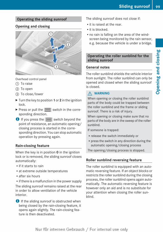
Operating the sliding sunroof
Opening and closing
Overhead control panel: To raise; To open= To close/lowerX Turn the key to position 1 or 2 in the ignition
lock.X Press or pull the 3 switch in the corre-
sponding direction.i If you press the 3 switch beyond the
point of resistance, an automatic opening/closing process is started in the corre-sponding direction. You can stop automaticoperation by pressing again.
Rain-closing featureWhen the key is in position 0 in the ignitionlock or is removed, the sliding sunroof closesautomatically:Rif it starts to rainRat extreme outside temperaturesRafter six hoursRif there is a malfunction in the power supplyThe sliding sunroof remains raised at the rearin order to allow ventilation of the vehicleinterior.
i If the sliding sunroof is obstructed whenbeing closed by the rain-closing feature, itopens again slightly. The rain-closing fea-ture is then deactivated.
The sliding sunroof does not close if:Rit is raised at the rear.Rit is blocked.Rno rain is falling on the area of the wind-
screen being monitored by the rain sensor,e.g. because the vehicle is under a bridge.
Operating the roller sunblind for thesliding sunroof
General notesThe roller sunblind shields the vehicle interiorfrom sunlight. The roller sunblind can only beopened and closed when the sliding sunroofis closed.
G WARNINGWhen opening or closing the roller sunblindparts of the body could be trapped betweenthe roller sunblind and the frame or slidingsunroof. There is a risk of injury.When opening or closing make sure that noparts of the body are in the sweep of the rollersunblind.If someone is trapped:Rrelease the switch immediately orRpress the switch in any direction during the
automatic opening/closing processThe opening/closing process is stopped.
Roller sunblind reversing featureThe roller sunblind is equipped with an auto-matic reversing feature. If an object blocks orrestricts the roller sunblind during the closingprocess, the roller sunblind opens again auto-matically. The automatic reversing feature ishowever only an aid and is no substitute foryour attention when closing the roller sun-blind.
Sliding sunroof 99
Open
ing
and
clos
ing
Z
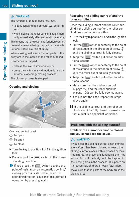
G WARNINGThe reversing function does not react:Rto soft, light and thin objects, e.g. small fin-
gersRwhen closing the roller sunblind again man-
ually immediately after automatic reversingThis means that the reversing function cannotprevent someone being trapped in these sit-uations. There is a risk of injury.When closing make sure that no parts of thebody are in the sweep of the roller sunblind.If someone is trapped:Rrelease the switch immediately orRpress the switch in any direction during the
automatic opening/closing processThe closing process is stopped.
Opening and closing
Overhead control panel: To open; To open= To closeX Turn the key to position 1 or 2 in the ignition
lock.X Press or pull the 3 switch in the corre-
sponding direction.i If you press the 3 switch beyond the
point of resistance, an automatic opening/closing process is started in the corre-sponding direction. You can stop automaticoperation by pressing again.
Resetting the sliding sunroof and theroller sunblindReset the sliding sunroof and the roller sun-blind if the sliding sunroof or the roller sun-blind does not move smoothly.X Turn the key to position 1 or 2 in the ignition
lock.X Pull the 3 switch repeatedly to the point
of resistance in the direction of arrow =until the sliding sunroof is fully closed.
X Keep the 3 switch pulled for an addi-tional second.
X Pull the 3 switch repeatedly to the pointof resistance in the direction of arrow =until the roller sunblind is fully closed.
X Keep the 3 switch pulled for an addi-tional second.
X Make sure that the sliding sunroof(Y page 99) and the roller sunblind(Y page 100) can be fully opened again.
X If this is not the case, repeat the stepsabove again.
! If the sliding sunroof and the roller sun-blind cannot be fully closed or reset, con-tact a qualified specialist workshop.
Problems with the sliding sunroofProblem: the sunroof cannot be closed and you cannot see the cause.
G WARNINGIf you close the sliding sunroof again immedi-ately after it has been blocked or reset, thesliding sunroof closes with increased or max-imum force. The reversing function is then notactive. Parts of the body could be trapped inthe closing area in the process. This poses anincreased risk of injury or even fatal injury.Make sure that no parts of the body are in theclosing area.
100 Sliding sunroofOp
enin
g an
d cl
osin
g
If someone is trapped:Rrelease the switch immediately orRpress the switch in any direction during the
automatic opening/closing processThe closing process is stopped.
If the sliding sunroof is obstructed duringclosing and reopens again slightly:X Immediately after the sliding sunroof
blocks, pull the 3 switch in the over-head control panel down to the point ofresistance and hold it until the sliding sun-roof is closed.The sliding sunroof is closed with increasedforce.
If the sliding sunroof is obstructed again dur-ing closing and reopens again slightly:X Immediately after the sliding sunroof
blocks, pull the 3 switch in the over-head control panel down to the point ofresistance and hold it until the sliding sun-roof is closed.The sliding sunroof is closed without theanti-entrapment feature.
Sliding sunroof 101
Open
ing
and
clos
ing
Z

102
Useful information ............................ 104Correct driver's seat position .......... 104Seats .................................................. 105Steering wheel .................................. 110Mirrors ............................................... 112Memory function .............................. 115
103
Seat
s, s
teer
ing
whe
el a
nd m
irror
s
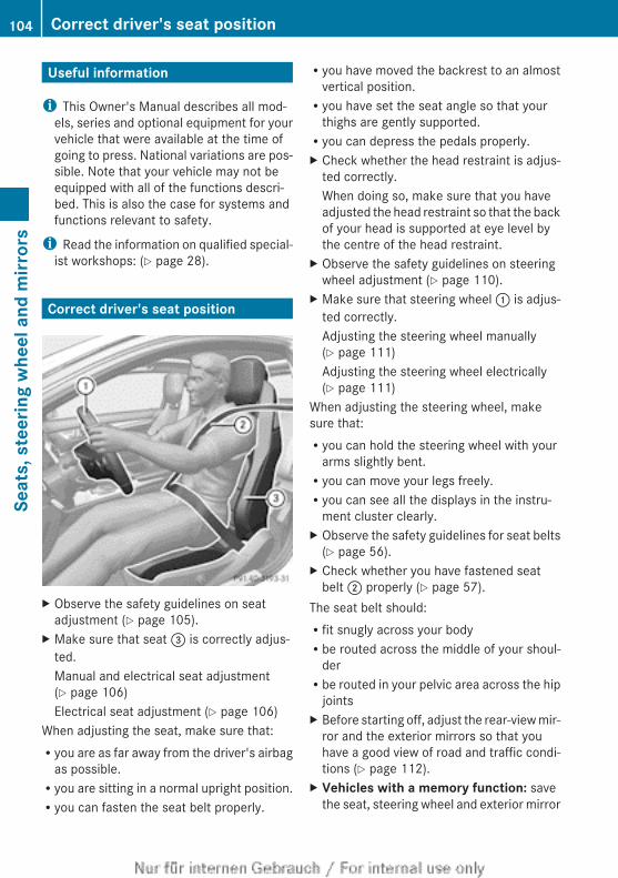
Useful information
i This Owner's Manual describes all mod-els, series and optional equipment for yourvehicle that were available at the time ofgoing to press. National variations are pos-sible. Note that your vehicle may not beequipped with all of the functions descri-bed. This is also the case for systems andfunctions relevant to safety.
i Read the information on qualified special-ist workshops: (Y page 28).
Correct driver's seat position
X Observe the safety guidelines on seatadjustment (Y page 105).
X Make sure that seat = is correctly adjus-ted.Manual and electrical seat adjustment(Y page 106)Electrical seat adjustment (Y page 106)
When adjusting the seat, make sure that:Ryou are as far away from the driver's airbag
as possible.Ryou are sitting in a normal upright position.Ryou can fasten the seat belt properly.
Ryou have moved the backrest to an almostvertical position.Ryou have set the seat angle so that your
thighs are gently supported.Ryou can depress the pedals properly.X Check whether the head restraint is adjus-
ted correctly.When doing so, make sure that you haveadjusted the head restraint so that the backof your head is supported at eye level bythe centre of the head restraint.
X Observe the safety guidelines on steeringwheel adjustment (Y page 110).
X Make sure that steering wheel : is adjus-ted correctly.Adjusting the steering wheel manually(Y page 111)Adjusting the steering wheel electrically(Y page 111)
When adjusting the steering wheel, makesure that:Ryou can hold the steering wheel with your
arms slightly bent.Ryou can move your legs freely.Ryou can see all the displays in the instru-
ment cluster clearly.X Observe the safety guidelines for seat belts
(Y page 56).X Check whether you have fastened seat
belt ; properly (Y page 57).The seat belt should:Rfit snugly across your bodyRbe routed across the middle of your shoul-
derRbe routed in your pelvic area across the hip
jointsX Before starting off, adjust the rear-view mir-
ror and the exterior mirrors so that youhave a good view of road and traffic condi-tions (Y page 112).
X Vehicles with a memory function: savethe seat, steering wheel and exterior mirror
104 Correct driver's seat positionSe
ats,
ste
erin
g w
heel
and
mirr
ors
settings with the memory function(Y page 115).
Seats
Important safety notes
G WARNINGIf children adjust the seats, they couldbecome trapped, especially if they are unat-tended. There is a risk of injury.When leaving the vehicle, always take the keywith you and lock the vehicle. Never leavechildren unattended in the vehicle.
G WARNINGYou could lose control of the vehicle whiledriving if you:Radjust the driver's seat, steering wheel or
mirrorsRfasten the seat beltThere is a risk of an accident.Adjust the driver's seat, head restraint, steer-ing wheel and mirrors and fasten your seatbelt before starting the engine.
G WARNINGIf you adjust the seat height carelessly, you orother vehicle occupants could be trapped andthereby injured. Children in particular couldaccidentally press the electrical seat adjust-ment buttons and become trapped. There isa risk of injury.While moving the seats, make sure that yourhands or other body parts do not get underthe lever assembly of the seat adjustmentsystem.
G WARNINGWhen adjusting a seat, you or another vehicleoccupant could become trapped by the guiderail of the seat, for instance. There is a risk ofinjury.
Make sure that no one has any part of theirbody within the sweep of the seat whenadjusting it.
G WARNINGThe head restraints cannot provide the inten-ded protection unless they are fitted andadjusted correctly. There is an increased riskof injury to the head and neck in the event ofan accident or sudden braking, for example.Always drive with the head restraints fitted.Ensure that the centre of the head restraintssupport the back of each vehicle occupant'shead at eye level before driving off.
G WARNINGThe seat belt does not offer the intended levelof protection if the backrest is not in theupright position. When braking or in the eventof an accident, you could slide underneath theseat belt and sustain abdomen or neck inju-ries, for example. This poses an increased riskof injury or even fatal injury.Adjust the seat properly before beginningyour journey. Always make sure that the seatis in the upright position.
! To avoid damage to the seats and the seatheating, observe the following information:Rdo not spill any liquids on the seats. If
liquid is spilled on the seats, dry them assoon as possible.Rif the seat covers are damp or wet, do not
switch on the seat heating. The seatheating should also not be used to drythe seats.Rclean the seat covers as recommended;
see the "Interior care" section.Rdo not transport heavy loads on the
seats. Do not place sharp objects on theseat cushions, e.g. knives, nails or tools.The seats should only be occupied bypassengers, if possible.Rwhen the seat heating is in operation, do
not cover the seats with insulating mate-
Seats 105
Seat
s, s
teer
ing
whe
el a
nd m
irror
s
Z
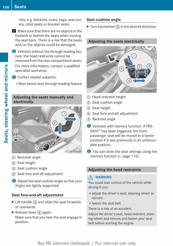
rials, e.g. blankets, coats, bags, seat cov-ers, child seats or booster seats.
! Make sure that there are no objects in thefootwell or behind the seats when movingthe seat back. There is a risk that the seatsand/or the objects could be damaged.
i Vehicles without the through-loading fea-ture: the head restraints cannot beremoved from the rear compartment seats.For more information, contact a qualifiedspecialist workshop.
i Further related subjects:RRear bench seat through-loading feature
Adjusting the seats manually andelectrically
: Backrest angle; Seat height= Seat cushion angle? Seat fore-and-aft adjustment
i Adjust the seat cushion angle so that yourthighs are lightly supported.
Seat fore-and-aft adjustmentX Lift handle ? and slide the seat forwards
or rearwards.X Release lever ? again.
Make sure that you hear the seat engage inposition.
Seat cushion angleX Turn handwheel = in the desired direction.
Adjusting the seats electrically
: Head restraint height; Seat cushion angle= Seat height? Seat fore-and-aft adjustmentA Backrest angle
i Vehicles with memory function: if PRE-SAFE® has been triggered, the front-passenger seat will be moved to a betterposition if it was previously in an unfavour-able position.
i You can store the seat settings using thememory function (Y page 115).
Adjusting the head restraints
G WARNINGYou could lose control of the vehicle whiledriving if you:Radjust the driver's seat, steering wheel or
mirrorsRfasten the seat beltThere is a risk of an accident.Adjust the driver's seat, head restraint, steer-ing wheel and mirrors and fasten your seatbelt before starting the engine.
106 SeatsSe
ats,
ste
erin
g w
heel
and
mirr
ors
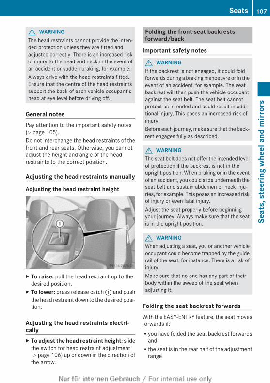
G WARNINGThe head restraints cannot provide the inten-ded protection unless they are fitted andadjusted correctly. There is an increased riskof injury to the head and neck in the event ofan accident or sudden braking, for example.Always drive with the head restraints fitted.Ensure that the centre of the head restraintssupport the back of each vehicle occupant'shead at eye level before driving off.
General notesPay attention to the important safety notes(Y page 105).Do not interchange the head restraints of thefront and rear seats. Otherwise, you cannotadjust the height and angle of the headrestraints to the correct position.
Adjusting the head restraints manually
Adjusting the head restraint height
X To raise: pull the head restraint up to thedesired position.
X To lower: press release catch : and pushthe head restraint down to the desired posi-tion.
Adjusting the head restraints electri-callyX To adjust the head restraint height: slide
the switch for head restraint adjustment(Y page 106) up or down in the direction ofthe arrow.
Folding the front-seat backrestsforward/back
Important safety notes
G WARNINGIf the backrest is not engaged, it could foldforwards during a braking manoeuvre or in theevent of an accident, for example. The seatbackrest will then push the vehicle occupantagainst the seat belt. The seat belt cannotprotect as intended and could result in addi-tional injury. This poses an increased risk ofinjury.Before each journey, make sure that the back-rest engages fully as described.
G WARNINGThe seat belt does not offer the intended levelof protection if the backrest is not in theupright position. When braking or in the eventof an accident, you could slide underneath theseat belt and sustain abdomen or neck inju-ries, for example. This poses an increased riskof injury or even fatal injury.Adjust the seat properly before beginningyour journey. Always make sure that the seatis in the upright position.
G WARNINGWhen adjusting a seat, you or another vehicleoccupant could become trapped by the guiderail of the seat, for instance. There is a risk ofinjury.Make sure that no one has any part of theirbody within the sweep of the seat whenadjusting it.
Folding the seat backrest forwardsWith the EASY-ENTRY feature, the seat movesforwards if:Ryou have folded the seat backrest forwards
andRthe seat is in the rear half of the adjustment
range
Seats 107
Seat
s, s
teer
ing
whe
el a
nd m
irror
s
Z
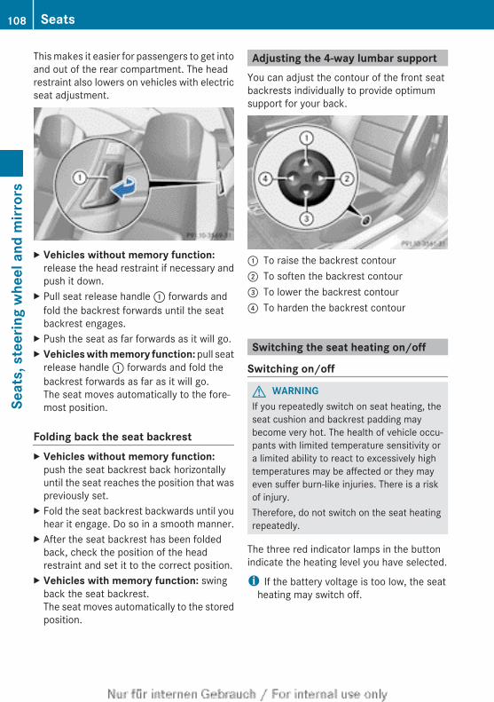
This makes it easier for passengers to get intoand out of the rear compartment. The headrestraint also lowers on vehicles with electricseat adjustment.
X Vehicles without memory function:release the head restraint if necessary andpush it down.
X Pull seat release handle : forwards andfold the backrest forwards until the seatbackrest engages.
X Push the seat as far forwards as it will go.X Vehicles with memory function: pull seat
release handle : forwards and fold thebackrest forwards as far as it will go.The seat moves automatically to the fore-most position.
Folding back the seat backrestX Vehicles without memory function:
push the seat backrest back horizontallyuntil the seat reaches the position that waspreviously set.
X Fold the seat backrest backwards until youhear it engage. Do so in a smooth manner.
X After the seat backrest has been foldedback, check the position of the headrestraint and set it to the correct position.
X Vehicles with memory function: swingback the seat backrest.The seat moves automatically to the storedposition.
Adjusting the 4-way lumbar supportYou can adjust the contour of the front seatbackrests individually to provide optimumsupport for your back.
: To raise the backrest contour; To soften the backrest contour= To lower the backrest contour? To harden the backrest contour
Switching the seat heating on/off
Switching on/off
G WARNINGIf you repeatedly switch on seat heating, theseat cushion and backrest padding maybecome very hot. The health of vehicle occu-pants with limited temperature sensitivity ora limited ability to react to excessively hightemperatures may be affected or they mayeven suffer burn-like injuries. There is a riskof injury.Therefore, do not switch on the seat heatingrepeatedly.
The three red indicator lamps in the buttonindicate the heating level you have selected.
i If the battery voltage is too low, the seatheating may switch off.
108 SeatsSe
ats,
ste
erin
g w
heel
and
mirr
ors
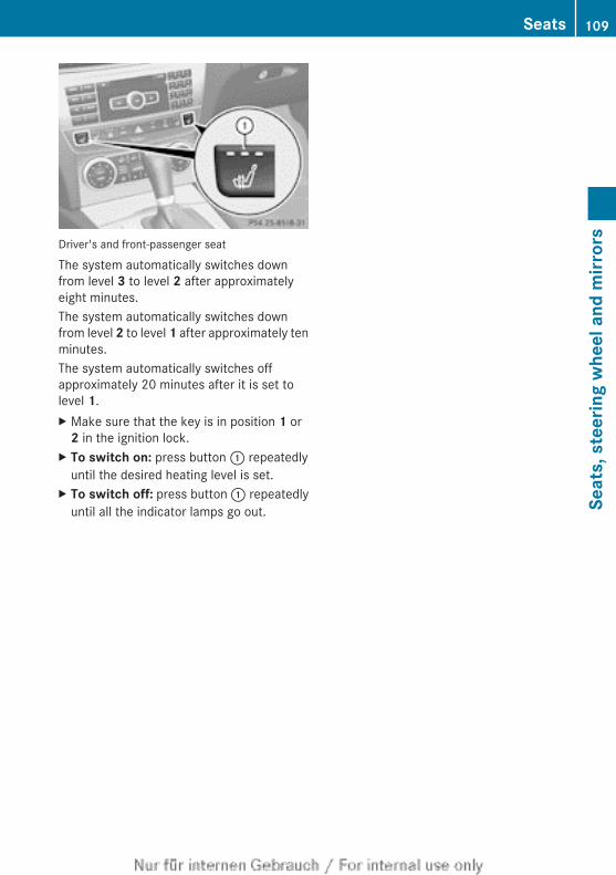
Driver's and front-passenger seat
The system automatically switches downfrom level 3 to level 2 after approximatelyeight minutes.The system automatically switches downfrom level 2 to level 1 after approximately tenminutes.The system automatically switches offapproximately 20 minutes after it is set tolevel 1.X Make sure that the key is in position 1 or
2 in the ignition lock.X To switch on: press button : repeatedly
until the desired heating level is set.X To switch off: press button : repeatedly
until all the indicator lamps go out.
Seats 109
Seat
s, s
teer
ing
whe
el a
nd m
irror
s
Z
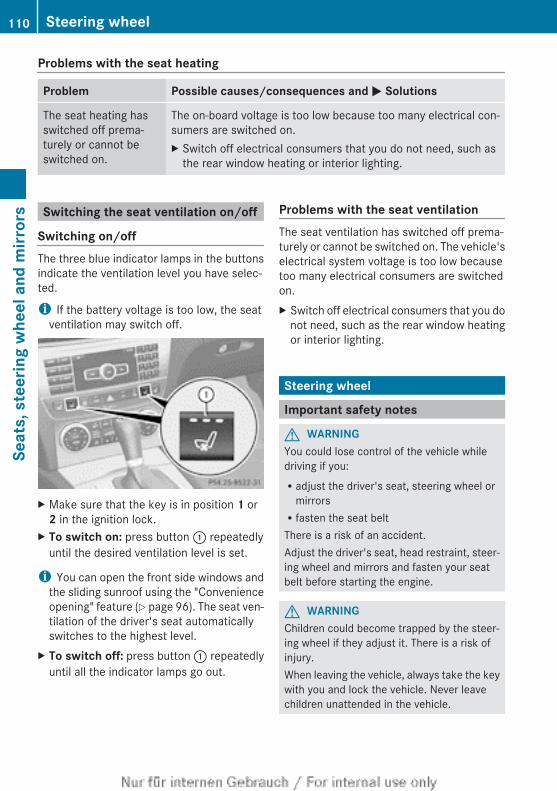
Problems with the seat heating
Problem Possible causes/consequences and M Solutions
The seat heating hasswitched off prema-turely or cannot beswitched on.
The on-board voltage is too low because too many electrical con-sumers are switched on.X Switch off electrical consumers that you do not need, such as
the rear window heating or interior lighting.
Switching the seat ventilation on/off
Switching on/offThe three blue indicator lamps in the buttonsindicate the ventilation level you have selec-ted.
i If the battery voltage is too low, the seatventilation may switch off.
X Make sure that the key is in position 1 or 2 in the ignition lock.
X To switch on: press button : repeatedlyuntil the desired ventilation level is set.
i You can open the front side windows andthe sliding sunroof using the "Convenienceopening" feature (Y page 96). The seat ven-tilation of the driver's seat automaticallyswitches to the highest level.
X To switch off: press button : repeatedlyuntil all the indicator lamps go out.
Problems with the seat ventilationThe seat ventilation has switched off prema-turely or cannot be switched on. The vehicle'selectrical system voltage is too low becausetoo many electrical consumers are switchedon.X Switch off electrical consumers that you do
not need, such as the rear window heatingor interior lighting.
Steering wheel
Important safety notes
G WARNINGYou could lose control of the vehicle whiledriving if you:Radjust the driver's seat, steering wheel or
mirrorsRfasten the seat beltThere is a risk of an accident.Adjust the driver's seat, head restraint, steer-ing wheel and mirrors and fasten your seatbelt before starting the engine.
G WARNINGChildren could become trapped by the steer-ing wheel if they adjust it. There is a risk ofinjury.When leaving the vehicle, always take the keywith you and lock the vehicle. Never leavechildren unattended in the vehicle.
110 Steering wheelSe
ats,
ste
erin
g w
heel
and
mirr
ors
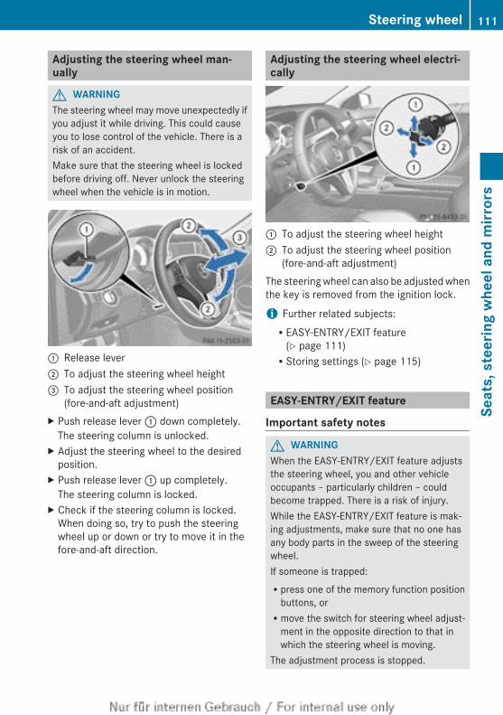
Adjusting the steering wheel man-ually
G WARNINGThe steering wheel may move unexpectedly ifyou adjust it while driving. This could causeyou to lose control of the vehicle. There is arisk of an accident.Make sure that the steering wheel is lockedbefore driving off. Never unlock the steeringwheel when the vehicle is in motion.
: Release lever; To adjust the steering wheel height= To adjust the steering wheel position
(fore-and-aft adjustment)X Push release lever : down completely.
The steering column is unlocked.X Adjust the steering wheel to the desired
position.X Push release lever : up completely.
The steering column is locked.X Check if the steering column is locked.
When doing so, try to push the steeringwheel up or down or try to move it in thefore-and-aft direction.
Adjusting the steering wheel electri-cally
: To adjust the steering wheel height; To adjust the steering wheel position
(fore-and-aft adjustment)The steering wheel can also be adjusted whenthe key is removed from the ignition lock.
i Further related subjects:REASY-ENTRY/EXIT feature
(Y page 111)RStoring settings (Y page 115)
EASY-ENTRY/EXIT feature
Important safety notes
G WARNINGWhen the EASY-ENTRY/EXIT feature adjuststhe steering wheel, you and other vehicleoccupants – particularly children – couldbecome trapped. There is a risk of injury.While the EASY-ENTRY/EXIT feature is mak-ing adjustments, make sure that no one hasany body parts in the sweep of the steeringwheel.If someone is trapped:Rpress one of the memory function position
buttons, orRmove the switch for steering wheel adjust-
ment in the opposite direction to that inwhich the steering wheel is moving.
The adjustment process is stopped.
Steering wheel 111
Seat
s, s
teer
ing
whe
el a
nd m
irror
s
Z
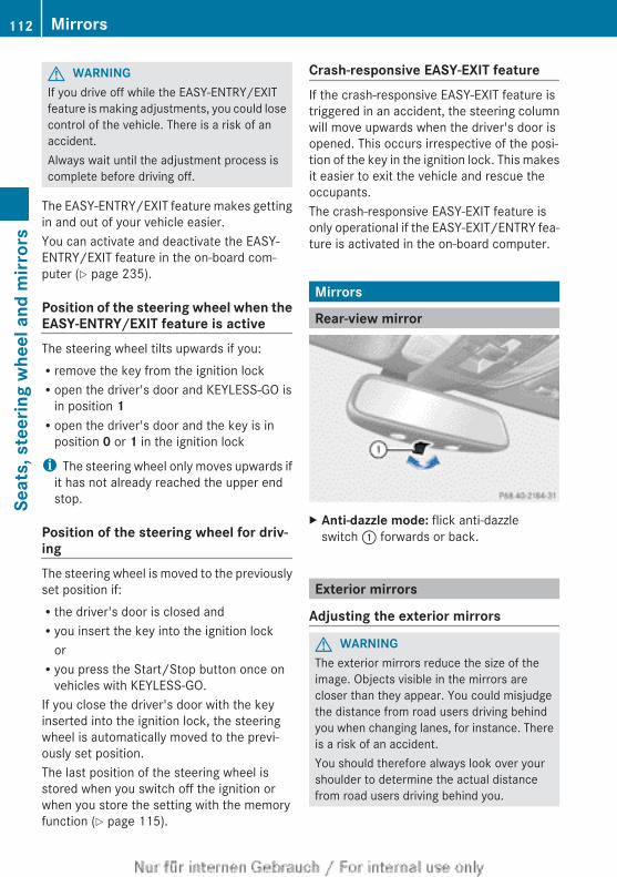
G WARNINGIf you drive off while the EASY-ENTRY/EXITfeature is making adjustments, you could losecontrol of the vehicle. There is a risk of anaccident.Always wait until the adjustment process iscomplete before driving off.
The EASY-ENTRY/EXIT feature makes gettingin and out of your vehicle easier.You can activate and deactivate the EASY-ENTRY/EXIT feature in the on-board com-puter (Y page 235).
Position of the steering wheel when theEASY-ENTRY/EXIT feature is activeThe steering wheel tilts upwards if you:Rremove the key from the ignition lockRopen the driver's door and KEYLESS-GO is
in position 1Ropen the driver's door and the key is in
position 0 or 1 in the ignition lock
i The steering wheel only moves upwards ifit has not already reached the upper endstop.
Position of the steering wheel for driv-ingThe steering wheel is moved to the previouslyset position if:Rthe driver's door is closed andRyou insert the key into the ignition lock
orRyou press the Start/Stop button once on
vehicles with KEYLESS-GO.If you close the driver's door with the keyinserted into the ignition lock, the steeringwheel is automatically moved to the previ-ously set position.The last position of the steering wheel isstored when you switch off the ignition orwhen you store the setting with the memoryfunction (Y page 115).
Crash-responsive EASY-EXIT featureIf the crash-responsive EASY-EXIT feature istriggered in an accident, the steering columnwill move upwards when the driver's door isopened. This occurs irrespective of the posi-tion of the key in the ignition lock. This makesit easier to exit the vehicle and rescue theoccupants.The crash-responsive EASY-EXIT feature isonly operational if the EASY-EXIT/ENTRY fea-ture is activated in the on-board computer.
Mirrors
Rear-view mirror
X Anti-dazzle mode: flick anti-dazzleswitch : forwards or back.
Exterior mirrors
Adjusting the exterior mirrors
G WARNINGThe exterior mirrors reduce the size of theimage. Objects visible in the mirrors arecloser than they appear. You could misjudgethe distance from road users driving behindyou when changing lanes, for instance. Thereis a risk of an accident.You should therefore always look over yourshoulder to determine the actual distancefrom road users driving behind you.
112 MirrorsSe
ats,
ste
erin
g w
heel
and
mirr
ors
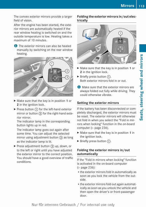
The convex exterior mirrors provide a largerfield of vision.After the engine has been started, the exte-rior mirrors are automatically heated if therear window heating is switched on and theoutside temperature is low. Heating takes amaximum of 10 minutes.
i The exterior mirrors can also be heatedmanually by switching on the rear windowheating.
X Make sure that the key is in position 1 or 2 in the ignition lock.
X Press button : for the left-hand exteriormirror or button ; for the right-hand exte-rior mirror.The indicator lamp in the correspondingbutton lights up in red.The indicator lamp goes out again aftersome time. You can adjust the selectedmirror using adjustment button = as longas the indicator lamp is lit.
X Press adjustment button = up, down, orto the left or right until you have adjustedthe exterior mirror to the correct position.You should have a good overview of trafficconditions.
Folding the exterior mirrors in/out elec-trically
X Make sure that the key is in position 1 or 2 in the ignition lock.
X Briefly press button :.Both exterior mirrors fold in or out.
i Make sure that the exterior mirrors arealways folded out fully while driving. Theycould otherwise vibrate.
Setting the exterior mirrorsIf the battery has been disconnected or com-pletely discharged, the exterior mirrors mustbe reset. The exterior mirrors will otherwisenot fold in when you select the "Fold in mir-rors when locking" function in the on-boardcomputer (Y page 236).X Make sure that the key is in position 1 in
the ignition lock.X Briefly press button :.
Folding the exterior mirrors in/outautomaticallyIf the "Fold in mirrors when locking" functionis activated in the on-board computer(Y page 236):Rthe exterior mirrors fold in automatically as
soon as you lock the vehicle from the out-side.Rthe exterior mirrors fold out again automat-
ically as soon as you unlock the vehicle andthen open the driver's or front-passengerdoor.
Mirrors 113
Seat
s, s
teer
ing
whe
el a
nd m
irror
s
Z
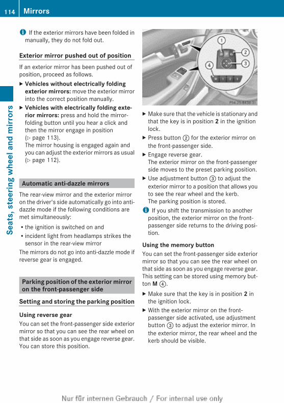
i If the exterior mirrors have been folded inmanually, they do not fold out.
Exterior mirror pushed out of positionIf an exterior mirror has been pushed out ofposition, proceed as follows.X Vehicles without electrically folding
exterior mirrors: move the exterior mirrorinto the correct position manually.
X Vehicles with electrically folding exte-rior mirrors: press and hold the mirror-folding button until you hear a click andthen the mirror engage in position(Y page 113).The mirror housing is engaged again andyou can adjust the exterior mirrors as usual(Y page 112).
Automatic anti-dazzle mirrorsThe rear-view mirror and the exterior mirroron the driver's side automatically go into anti-dazzle mode if the following conditions aremet simultaneously:Rthe ignition is switched on andRincident light from headlamps strikes the
sensor in the rear-view mirrorThe mirrors do not go into anti-dazzle mode ifreverse gear is engaged.
Parking position of the exterior mirroron the front-passenger side
Setting and storing the parking position
Using reverse gearYou can set the front-passenger side exteriormirror so that you can see the rear wheel onthat side as soon as you engage reverse gear.You can store this position.
X Make sure that the vehicle is stationary andthat the key is in position 2 in the ignitionlock.
X Press button ; for the exterior mirror onthe front-passenger side.
X Engage reverse gear.The exterior mirror on the front-passengerside moves to the preset parking position.
X Use adjustment button = to adjust theexterior mirror to a position that allows youto see the rear wheel and the kerb.The parking position is stored.
i If you shift the transmission to anotherposition, the exterior mirror on the front-passenger side returns to the driving posi-tion.
Using the memory buttonYou can set the front-passenger side exteriormirror so that you can see the rear wheel onthat side as soon as you engage reverse gear.This setting can be stored using memory but-ton M ?.X Make sure that the key is in position 2 in
the ignition lock.X With the exterior mirror on the front-
passenger side activated, use adjustmentbutton = to adjust the exterior mirror. Inthe exterior mirror, the rear wheel and thekerb should be visible.
114 MirrorsSe
ats,
ste
erin
g w
heel
and
mirr
ors
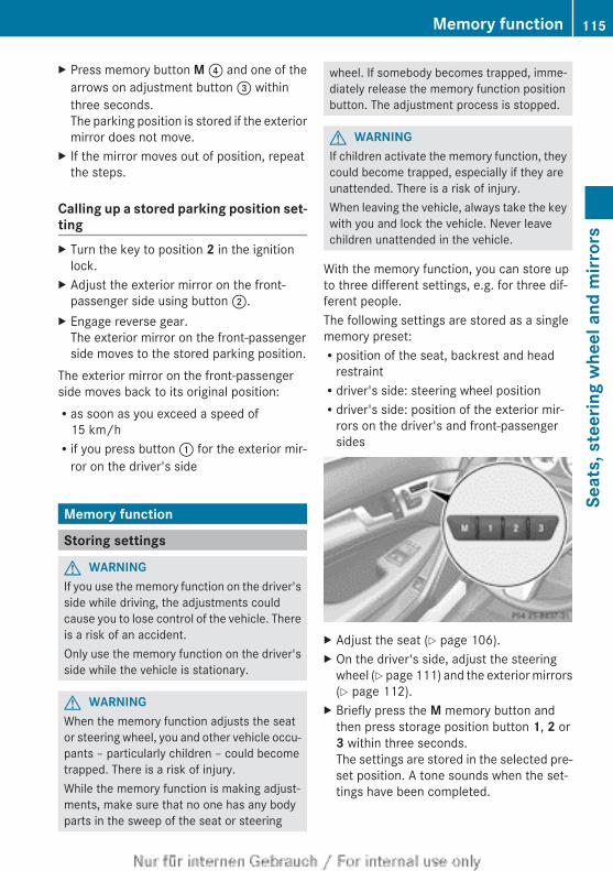
X Press memory button M ? and one of thearrows on adjustment button = withinthree seconds.The parking position is stored if the exteriormirror does not move.
X If the mirror moves out of position, repeatthe steps.
Calling up a stored parking position set-tingX Turn the key to position 2 in the ignition
lock.X Adjust the exterior mirror on the front-
passenger side using button ;.X Engage reverse gear.
The exterior mirror on the front-passengerside moves to the stored parking position.
The exterior mirror on the front-passengerside moves back to its original position:Ras soon as you exceed a speed of
15 km/hRif you press button : for the exterior mir-
ror on the driver's side
Memory function
Storing settings
G WARNINGIf you use the memory function on the driver'sside while driving, the adjustments couldcause you to lose control of the vehicle. Thereis a risk of an accident.Only use the memory function on the driver'sside while the vehicle is stationary.
G WARNINGWhen the memory function adjusts the seator steering wheel, you and other vehicle occu-pants – particularly children – could becometrapped. There is a risk of injury.While the memory function is making adjust-ments, make sure that no one has any bodyparts in the sweep of the seat or steering
wheel. If somebody becomes trapped, imme-diately release the memory function positionbutton. The adjustment process is stopped.
G WARNINGIf children activate the memory function, theycould become trapped, especially if they areunattended. There is a risk of injury.When leaving the vehicle, always take the keywith you and lock the vehicle. Never leavechildren unattended in the vehicle.
With the memory function, you can store upto three different settings, e.g. for three dif-ferent people.The following settings are stored as a singlememory preset:Rposition of the seat, backrest and head
restraintRdriver's side: steering wheel positionRdriver's side: position of the exterior mir-
rors on the driver's and front-passengersides
X Adjust the seat (Y page 106).X On the driver's side, adjust the steering
wheel (Y page 111) and the exterior mirrors(Y page 112).
X Briefly press the M memory button andthen press storage position button 1, 2 or3 within three seconds.The settings are stored in the selected pre-set position. A tone sounds when the set-tings have been completed.
Memory function 115
Seat
s, s
teer
ing
whe
el a
nd m
irror
s
Z
Calling up a stored setting! If you want to move the seat from the fully
reclined position to a stored seat position,first raise the backrest. The seat could oth-erwise be damaged.
X Press and hold the relevant storage posi-tion button 1, 2 or 3 until the seat, steeringwheel and exterior mirrors are in the storedposition.
i The setting procedure is interrupted assoon as you release the storage positionbutton.
116 Memory functionSe
ats,
ste
erin
g w
heel
and
mirr
ors
Useful information ............................ 118Exterior lighting ................................ 118Interior lighting ................................. 125Replacing bulbs ................................. 125Windscreen wipers ........................... 129
117
Ligh
ts a
nd w
inds
cree
n w
iper
s
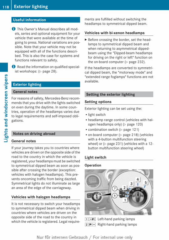
Useful information
i This Owner's Manual describes all mod-els, series and optional equipment for yourvehicle that were available at the time ofgoing to press. National variations are pos-sible. Note that your vehicle may not beequipped with all of the functions descri-bed. This is also the case for systems andfunctions relevant to safety.
i Read the information on qualified special-ist workshops: (Y page 28).
Exterior lighting
General notesFor reasons of safety, Mercedes-Benz recom-mends that you drive with the lights switchedon even during the daytime. In some coun-tries, operation of the headlamps varies dueto legal requirements and self-imposed obli-gations.
Notes on driving abroad
General notesIf your journey takes you to countries wherevehicles are driven on the opposite side of theroad to the country in which the vehicle isregistered, your headlamps must be switchedto symmetrical dipped beam as soon as pos-sible after crossing the border (exception:vehicles with halogen headlamps). This pre-vents oncoming traffic from being dazzled.Symmetrical lights do not illuminate as largean area of the edge of the carriageway.
Vehicles with halogen headlampsIt is not necessary to switch your headlampsto symmetrical dipped beam when driving incountries where vehicles are driven on theopposite side of the road to the country inwhich the vehicle is registered. Legal require-
ments are fulfilled without switching theheadlamps to symmetrical dipped beam.
Vehicles with bi-xenon headlampsX Before crossing the border, set the head-
lamps to symmetrical dipped beam andwhen returning to asymmetrical dipped-beam using the "Dipped-beam headlampsfor driving on the right or left" function onthe on-board computer (Y page 232).
If the headlamps are converted to symmetri-cal dipped beam, the "motorway mode" and"extended range foglamps" functions are notavailable.
Setting the exterior lighting
Setting optionsExterior lighting can be set using the:Rlight switchRheadlamp range control (vehicles with hal-
ogen headlamps only) (Y page 120)Rcombination switch (Y page 121)Ron-board computer (Y page 218) (vehicles
with a 4-button multifunction steeringwheel) or (Y page 231) (vehicles with a 12-button multifunction steering wheel)
Light switch
Operation
1W Left-hand parking lamps2X Right-hand parking lamps
118 Exterior lightingLi
ghts
and
win
dscr
een
wip
ers
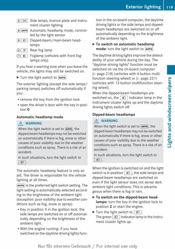
3T Side lamps, licence plate and instru-ment cluster lighting
4Ã Automatic headlamp mode, control-led by the light sensor
5L Dipped-beam/main-beam head-lamps
BR Rear fog lampCN Foglamp (vehicles with front fog-
lamps only)If you hear a warning tone when you leave thevehicle, the lights may still be switched on.X Turn the light switch to Ã.The exterior lighting (except the side lamps/parking lamps) switches off automatically ifyou:Rremove the key from the ignition lockRopen the driver's door with the key in posi-
tion 0
Automatic headlamp modeG WARNINGWhen the light switch is set to Ã, thedipped-beam headlamps may not be switchedon automatically if there is fog, snow or othercauses of poor visibility due to the weatherconditions such as spray. There is a risk of anaccident.In such situations, turn the light switch toL.
The automatic headlamp feature is only anaid. The driver is responsible for the vehiclelighting at all times.Ã is the preferred light switch setting. Thelight setting is automatically selected accord-ing to the brightness of the ambient light(exception: poor visibility due to weather con-ditions such as fog, snow or spray):RKey in position 1 in the ignition lock: the
side lamps are switched on or off automat-ically depending on the brightness of theambient light.RWith the engine running: if you have
switched on the daytime driving lights func-
tion in the on-board computer, the daytimedriving lights or the side lamps and dipped-beam headlamps are switched on or offautomatically depending on the brightnessof the ambient light.
X To switch on automatic headlamp mode: turn the light switch to Ã.
The daytime driving lights improve the detect-ability of your vehicle during the day. The"daytime driving lights" function must beswitched on via the on-board computer(Y page 218) (vehicles with 4-button multi-function steering wheel) or (Y page 231)(vehicles with 12-button multifunction steer-ing wheel).When the dipped-beam headlamps areswitched on, the L indicator lamp in theinstrument cluster lights up and the daytimedriving lights switch off.
Dipped-beam headlampsG WARNINGWhen the light switch is set to Ã, thedipped-beam headlamps may not be switchedon automatically if there is fog, snow or othercauses of poor visibility due to the weatherconditions such as spray. There is a risk of anaccident.In such situations, turn the light switch toL.
When the ignition is switched on and the lightswitch is in position L, the side lamps anddipped-beam headlamps are switched oneven if the light sensor does not sense darkambient light conditions. This is advanta-geous when there is fog or rain.X To switch on the dipped-beam head-
lamps: turn the key in the ignition lock toposition 2 or start the engine.
X Turn the light switch to L.The green L indicator lamp in the instru-ment cluster lights up.
Exterior lighting 119
Ligh
ts a
nd w
inds
cree
n w
iper
s
Z
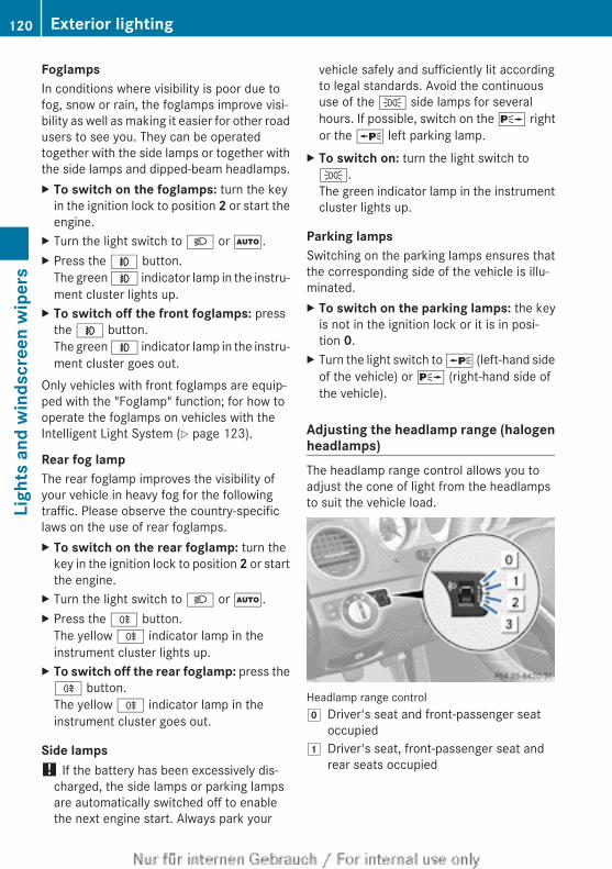
FoglampsIn conditions where visibility is poor due tofog, snow or rain, the foglamps improve visi-bility as well as making it easier for other roadusers to see you. They can be operatedtogether with the side lamps or together withthe side lamps and dipped-beam headlamps.X To switch on the foglamps: turn the key
in the ignition lock to position 2 or start theengine.
X Turn the light switch to L or Ã.X Press the N button.
The green N indicator lamp in the instru-ment cluster lights up.
X To switch off the front foglamps: pressthe N button.The green N indicator lamp in the instru-ment cluster goes out.
Only vehicles with front foglamps are equip-ped with the "Foglamp" function; for how tooperate the foglamps on vehicles with theIntelligent Light System (Y page 123).
Rear fog lampThe rear foglamp improves the visibility ofyour vehicle in heavy fog for the followingtraffic. Please observe the country-specificlaws on the use of rear foglamps.X To switch on the rear foglamp: turn the
key in the ignition lock to position 2 or startthe engine.
X Turn the light switch to L or Ã.X Press the R button.
The yellow R indicator lamp in theinstrument cluster lights up.
X To switch off the rear foglamp: press theR button.The yellow R indicator lamp in theinstrument cluster goes out.
Side lamps! If the battery has been excessively dis-
charged, the side lamps or parking lampsare automatically switched off to enablethe next engine start. Always park your
vehicle safely and sufficiently lit accordingto legal standards. Avoid the continuoususe of the T side lamps for severalhours. If possible, switch on the X rightor the W left parking lamp.
X To switch on: turn the light switch toT.The green indicator lamp in the instrumentcluster lights up.
Parking lampsSwitching on the parking lamps ensures thatthe corresponding side of the vehicle is illu-minated.X To switch on the parking lamps: the key
is not in the ignition lock or it is in posi-tion 0.
X Turn the light switch to W (left-hand sideof the vehicle) or X (right-hand side ofthe vehicle).
Adjusting the headlamp range (halogenheadlamps)The headlamp range control allows you toadjust the cone of light from the headlampsto suit the vehicle load.
Headlamp range controlg Driver's seat and front-passenger seat
occupied1 Driver's seat, front-passenger seat and
rear seats occupied
120 Exterior lightingLi
ghts
and
win
dscr
een
wip
ers
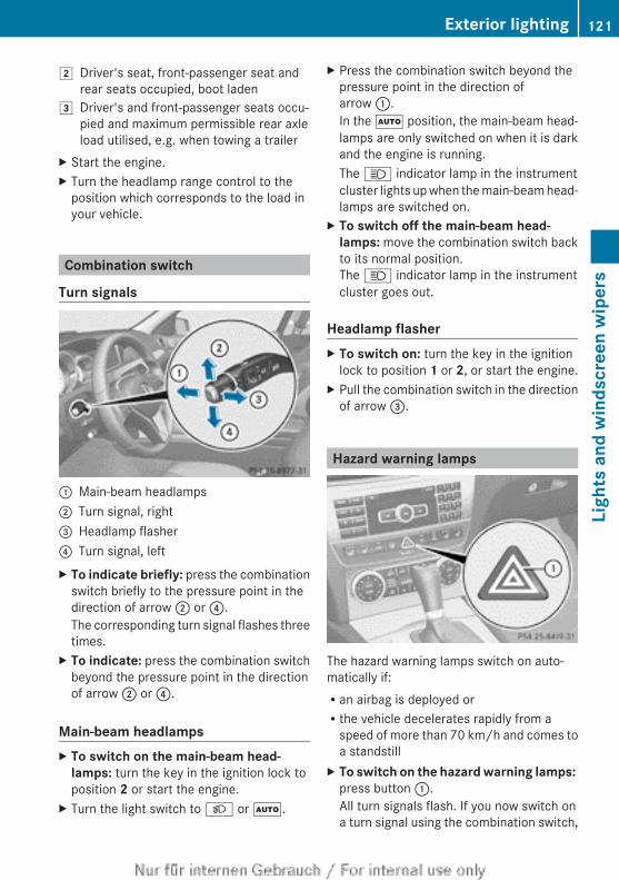
2 Driver's seat, front-passenger seat andrear seats occupied, boot laden
3 Driver's and front-passenger seats occu-pied and maximum permissible rear axleload utilised, e.g. when towing a trailer
X Start the engine.X Turn the headlamp range control to the
position which corresponds to the load inyour vehicle.
Combination switch
Turn signals
: Main-beam headlamps; Turn signal, right= Headlamp flasher? Turn signal, leftX To indicate briefly: press the combination
switch briefly to the pressure point in thedirection of arrow ; or ?.The corresponding turn signal flashes threetimes.
X To indicate: press the combination switchbeyond the pressure point in the directionof arrow ; or ?.
Main-beam headlampsX To switch on the main-beam head-
lamps: turn the key in the ignition lock toposition 2 or start the engine.
X Turn the light switch to L or Ã.
X Press the combination switch beyond thepressure point in the direction ofarrow :.In the à position, the main-beam head-lamps are only switched on when it is darkand the engine is running.The K indicator lamp in the instrumentcluster lights up when the main-beam head-lamps are switched on.
X To switch off the main-beam head-lamps: move the combination switch backto its normal position.The K indicator lamp in the instrumentcluster goes out.
Headlamp flasherX To switch on: turn the key in the ignition
lock to position 1 or 2, or start the engine.X Pull the combination switch in the direction
of arrow =.
Hazard warning lamps
The hazard warning lamps switch on auto-matically if:Ran airbag is deployed orRthe vehicle decelerates rapidly from a
speed of more than 70 km/h and comes toa standstill
X To switch on the hazard warning lamps: press button :.All turn signals flash. If you now switch ona turn signal using the combination switch,
Exterior lighting 121
Ligh
ts a
nd w
inds
cree
n w
iper
s
Z
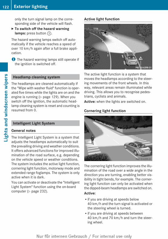
only the turn signal lamp on the corre-sponding side of the vehicle will flash.
X To switch off the hazard warning lamps: press button :.
The hazard warning lamps switch off auto-matically if the vehicle reaches a speed ofover 10 km/h again after a full brake appli-cation.
i The hazard warning lamps still operate ifthe ignition is switched off.
Headlamp cleaning systemThe headlamps are cleaned automatically ifthe "Wipe with washer fluid" function is oper-ated five times while the lights are on and theengine is running (Y page 129). When youswitch off the ignition, the automatic head-lamp cleaning system is reset and counting isresumed from 0.
Intelligent Light System
General notesThe Intelligent Light System is a system thatadjusts the headlamps automatically to suitthe prevailing driving and weather conditions.It offers advanced functions for improved illu-mination of the road surface, e.g. dependingon the vehicle speed or weather conditions.The system includes the active light function,cornering light function, motorway mode andextended range foglamps. The system is onlyactive when it is dark.You can activate or deactivate the "IntelligentLight System" function using the on-boardcomputer (Y page 232).
Active light function
The active light function is a system thatmoves the headlamps according to the steer-ing movements of the front wheels. In thisway, relevant areas remain illuminated whiledriving. This allows you to recognise pedes-trians, cyclists and animals.Active: when the lights are switched on.
Cornering light function
The cornering light function improves the illu-mination of the road over a wide angle in thedirection you are turning, enabling better vis-ibility in tight bends, for example. The corner-ing light function can only be activated whenthe dipped-beam headlamps are switched on.Active: Rif you are driving at speeds below
40 km/h and the turn signal is activated orthe steering wheel is turned.Rif you are driving at speeds between
40 km/h and 70 km/h and turn the steer-ing wheel.
122 Exterior lightingLi
ghts
and
win
dscr
een
wip
ers
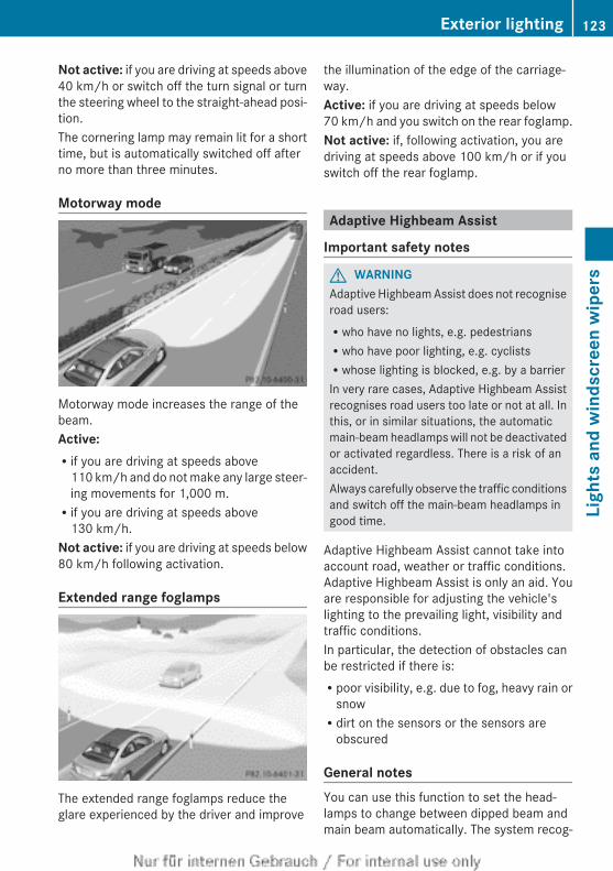
Not active: if you are driving at speeds above40 km/h or switch off the turn signal or turnthe steering wheel to the straight-ahead posi-tion.The cornering lamp may remain lit for a shorttime, but is automatically switched off afterno more than three minutes.
Motorway mode
Motorway mode increases the range of thebeam.Active: Rif you are driving at speeds above
110 km/h and do not make any large steer-ing movements for 1,000 m.Rif you are driving at speeds above
130 km/h.Not active: if you are driving at speeds below80 km/h following activation.
Extended range foglamps
The extended range foglamps reduce theglare experienced by the driver and improve
the illumination of the edge of the carriage-way.Active: if you are driving at speeds below70 km/h and you switch on the rear foglamp.Not active: if, following activation, you aredriving at speeds above 100 km/h or if youswitch off the rear foglamp.
Adaptive Highbeam Assist
Important safety notes
G WARNINGAdaptive Highbeam Assist does not recogniseroad users:Rwho have no lights, e.g. pedestriansRwho have poor lighting, e.g. cyclistsRwhose lighting is blocked, e.g. by a barrierIn very rare cases, Adaptive Highbeam Assistrecognises road users too late or not at all. Inthis, or in similar situations, the automaticmain-beam headlamps will not be deactivatedor activated regardless. There is a risk of anaccident.Always carefully observe the traffic conditionsand switch off the main-beam headlamps ingood time.
Adaptive Highbeam Assist cannot take intoaccount road, weather or traffic conditions.Adaptive Highbeam Assist is only an aid. Youare responsible for adjusting the vehicle'slighting to the prevailing light, visibility andtraffic conditions.In particular, the detection of obstacles canbe restricted if there is:Rpoor visibility, e.g. due to fog, heavy rain or
snowRdirt on the sensors or the sensors are
obscured
General notesYou can use this function to set the head-lamps to change between dipped beam andmain beam automatically. The system recog-
Exterior lighting 123
Ligh
ts a
nd w
inds
cree
n w
iper
s
Z
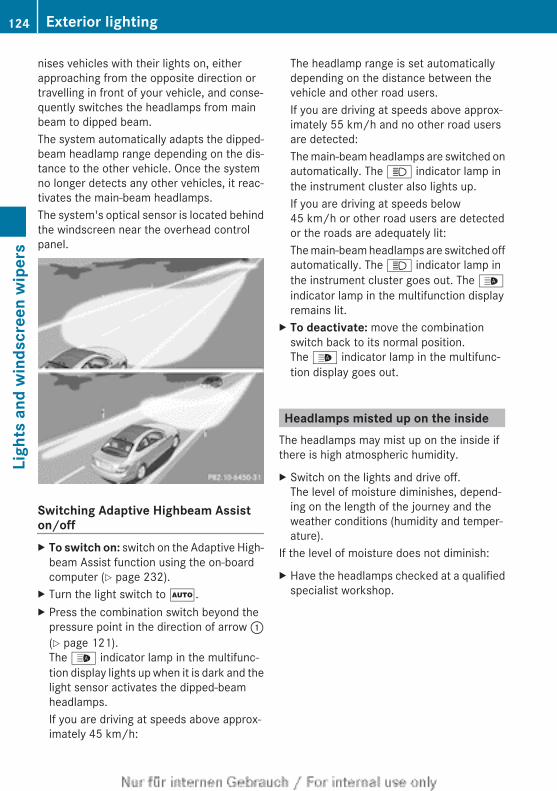
nises vehicles with their lights on, eitherapproaching from the opposite direction ortravelling in front of your vehicle, and conse-quently switches the headlamps from mainbeam to dipped beam.The system automatically adapts the dipped-beam headlamp range depending on the dis-tance to the other vehicle. Once the systemno longer detects any other vehicles, it reac-tivates the main-beam headlamps.The system's optical sensor is located behindthe windscreen near the overhead controlpanel.
Switching Adaptive Highbeam Assiston/offX To switch on: switch on the Adaptive High-
beam Assist function using the on-boardcomputer (Y page 232).
X Turn the light switch to Ã.X Press the combination switch beyond the
pressure point in the direction of arrow :(Y page 121).The _ indicator lamp in the multifunc-tion display lights up when it is dark and thelight sensor activates the dipped-beamheadlamps.If you are driving at speeds above approx-imately 45 km/h:
The headlamp range is set automaticallydepending on the distance between thevehicle and other road users.If you are driving at speeds above approx-imately 55 km/h and no other road usersare detected:The main-beam headlamps are switched onautomatically. The K indicator lamp inthe instrument cluster also lights up.If you are driving at speeds below45 km/h or other road users are detectedor the roads are adequately lit:The main-beam headlamps are switched offautomatically. The K indicator lamp inthe instrument cluster goes out. The _indicator lamp in the multifunction displayremains lit.
X To deactivate: move the combinationswitch back to its normal position.The _ indicator lamp in the multifunc-tion display goes out.
Headlamps misted up on the insideThe headlamps may mist up on the inside ifthere is high atmospheric humidity.
X Switch on the lights and drive off.The level of moisture diminishes, depend-ing on the length of the journey and theweather conditions (humidity and temper-ature).
If the level of moisture does not diminish:
X Have the headlamps checked at a qualifiedspecialist workshop.
124 Exterior lightingLi
ghts
and
win
dscr
een
wip
ers
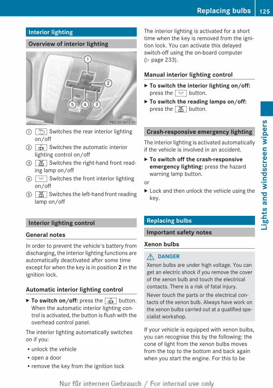
Interior lighting
Overview of interior lighting
: u Switches the rear interior lightingon/off
; | Switches the automatic interiorlighting control on/off
= p Switches the right-hand front read-ing lamp on/off
? c Switches the front interior lightingon/off
A p Switches the left-hand front readinglamp on/off
Interior lighting control
General notesIn order to prevent the vehicle's battery fromdischarging, the interior lighting functions areautomatically deactivated after some timeexcept for when the key is in position 2 in theignition lock.
Automatic interior lighting controlX To switch on/off: press the | button.
When the automatic interior lighting con-trol is activated, the button is flush with theoverhead control panel.
The interior lighting automatically switcheson if you:Runlock the vehicleRopen a doorRremove the key from the ignition lock
The interior lighting is activated for a shorttime when the key is removed from the igni-tion lock. You can activate this delayedswitch-off using the on-board computer(Y page 233).
Manual interior lighting controlX To switch the interior lighting on/off:
press the c button.X To switch the reading lamps on/off:
press the p button.
Crash-responsive emergency lightingThe interior lighting is activated automaticallyif the vehicle is involved in an accident.X To switch off the crash-responsive
emergency lighting: press the hazardwarning lamp button.
orX Lock and then unlock the vehicle using the
key.
Replacing bulbs
Important safety notes
Xenon bulbs
G DANGERXenon bulbs are under high voltage. You canget an electric shock if you remove the coverof the xenon bulb and touch the electricalcontacts. There is a risk of fatal injury.Never touch the parts or the electrical con-tacts of the xenon bulb. Always have work onthe xenon bulbs carried out at a qualified spe-cialist workshop.
If your vehicle is equipped with xenon bulbs,you can recognise this by the following: thecone of light from the xenon bulbs movesfrom the top to the bottom and back againwhen you start the engine. For this to be
Replacing bulbs 125
Ligh
ts a
nd w
inds
cree
n w
iper
s
Z
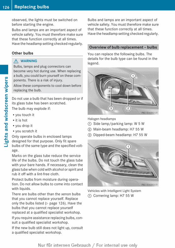
observed, the lights must be switched onbefore starting the engine.Bulbs and lamps are an important aspect ofvehicle safety. You must therefore make surethat these function correctly at all times.Have the headlamp setting checked regularly.
Other bulbs
G WARNINGBulbs, lamps and plug connectors canbecome very hot during use. When replacinga bulb, you could burn yourself on these com-ponents. There is a risk of injury.Allow these components to cool down beforereplacing the bulb.
Do not use a bulb that has been dropped or ifits glass tube has been scratched.The bulb may explode if:Ryou touch itRit is hotRyou drop itRyou scratch itOnly operate bulbs in enclosed lampsdesigned for that purpose. Only fit sparebulbs of the same type and the specified volt-age.Marks on the glass tube reduce the servicelife of the bulbs. Do not touch the glass tubewith your bare hands. If necessary, clean theglass tube when cold with alcohol or spirit andrub it off with a lint-free cloth.Protect bulbs from moisture during opera-tion. Do not allow bulbs to come into contactwith liquids.There are bulbs other than the xenon bulbsthat you cannot replace yourself. Replaceonly the bulbs listed (Y page 126). Have thebulbs that you cannot replace yourselfreplaced at a qualified specialist workshop.If you require assistance replacing bulbs, con-sult a qualified specialist workshop.If the new bulb still does not light up, consulta qualified specialist workshop.
Bulbs and lamps are an important aspect ofvehicle safety. You must therefore make surethat these function correctly at all times.Have the headlamp setting checked regularly.
Overview of bulb replacement – bulbsYou can replace the following bulbs. Thedetails for the bulb type can be found in thelegend.
Halogen headlamps: Side lamp/parking lamp: W 5 W; Main-beam headlamp: H7 55 W= Dipped-beam headlamp: H7 55 W
Vehicles with Intelligent Light System: Cornering lamp: H7 55 W
126 Replacing bulbsLi
ghts
and
win
dscr
een
wip
ers
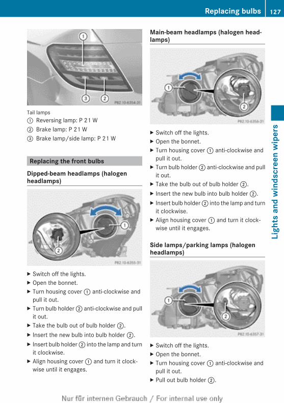
Tail lamps: Reversing lamp: P 21 W; Brake lamp: P 21 W= Brake lamp/side lamp: P 21 W
Replacing the front bulbs
Dipped-beam headlamps (halogenheadlamps)
X Switch off the lights.X Open the bonnet.X Turn housing cover : anti-clockwise and
pull it out.X Turn bulb holder ; anti-clockwise and pull
it out.X Take the bulb out of bulb holder ;.X Insert the new bulb into bulb holder ;.X Insert bulb holder ; into the lamp and turn
it clockwise.X Align housing cover : and turn it clock-
wise until it engages.
Main-beam headlamps (halogen head-lamps)
X Switch off the lights.X Open the bonnet.X Turn housing cover : anti-clockwise and
pull it out.X Turn bulb holder ; anti-clockwise and pull
it out.X Take the bulb out of bulb holder ;.X Insert the new bulb into bulb holder ;.X Insert bulb holder ; into the lamp and turn
it clockwise.X Align housing cover : and turn it clock-
wise until it engages.
Side lamps/parking lamps (halogenheadlamps)
X Switch off the lights.X Open the bonnet.X Turn housing cover : anti-clockwise and
pull it out.X Pull out bulb holder ;.
Replacing bulbs 127
Ligh
ts a
nd w
inds
cree
n w
iper
s
Z
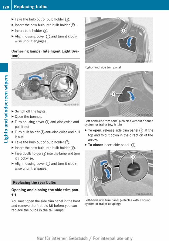
X Take the bulb out of bulb holder ;.X Insert the new bulb into bulb holder ;.X Insert bulb holder ;.X Align housing cover : and turn it clock-
wise until it engages.
Cornering lamps (Intelligent Light Sys-tem)
X Switch off the lights.X Open the bonnet.X Turn housing cover : anti-clockwise and
pull it out.X Turn bulb holder ; anti-clockwise and pull
it out.X Take the bulb out of bulb holder ;.X Insert the new bulb into bulb holder ;.X Insert bulb holder ; into the lamp and turn
it clockwise.X Align housing cover : and turn it clock-
wise until it engages.
Replacing the rear bulbs
Opening and closing the side trim pan-elsYou must open the side trim panel in the bootand remove the first-aid kit before you canreplace the bulbs in the tail lamps.
Right-hand side trim panel
Left-hand side trim panel (vehicles without a soundsystem or trailer tow hitch)X To open: release side trim panel : at the
top and fold it down in the direction of thearrow.
X To close: insert side panel :.
Left-hand side trim panel (vehicles with a soundsystem or trailer coupling)
128 Replacing bulbsLi
ghts
and
win
dscr
een
wip
ers
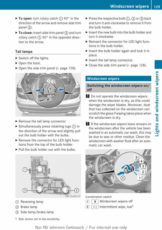
X To open: turn rotary catch : 90° in thedirection of the arrow and remove side trimpanel ;.
X To close: insert side trim panel ; and turnrotary catch : 90° in the opposite direc-tion to the arrow.
Tail lampsX Switch off the lights.X Open the boot.X Open the side trim panel (Y page 128).
X Remove the tail lamp connectorX Simultaneously press retaining lugs : in
the direction of the arrow and slightly pullout the bulb holder with the bulbs.
X Remove the connector for LED light func-tions from the top of the bulb holder.
X Pull the bulb holder out with the bulbs.
: Reversing lamp; Brake lamp= Side lamp/brake lamp
X Press the respective bulb :, ; or = backand turn it anti-clockwise to remove it fromthe bulb holder.
X Insert the new bulb into the bulb holder andturn it clockwise.
X Reinsert the connector for LED light func-tions in the bulb holder.
X Insert the bulb holder again and lock it inplace.
X Insert the tail lamp connector.X Close the side trim panel (Y page 128).
Windscreen wipers
Switching the windscreen wipers on/off
! Do not operate the windscreen wiperswhen the windscreen is dry, as this coulddamage the wiper blades. Moreover, dustthat has collected on the windscreen canscratch the glass if wiping takes place whenthe windscreen is dry.
! If the windscreen wipers leave smears onthe windscreen after the vehicle has beenwashed in an automatic car wash, this maybe due to wax or other residue. Clean thewindscreen with washer fluid after an auto-matic car wash.
Combination switch1 $ Windscreen wipers off2 Ä Intermittent wipe, low5
5 Rain sensor set to low sensitivity.
Windscreen wipers 129
Ligh
ts a
nd w
inds
cree
n w
iper
s
Z
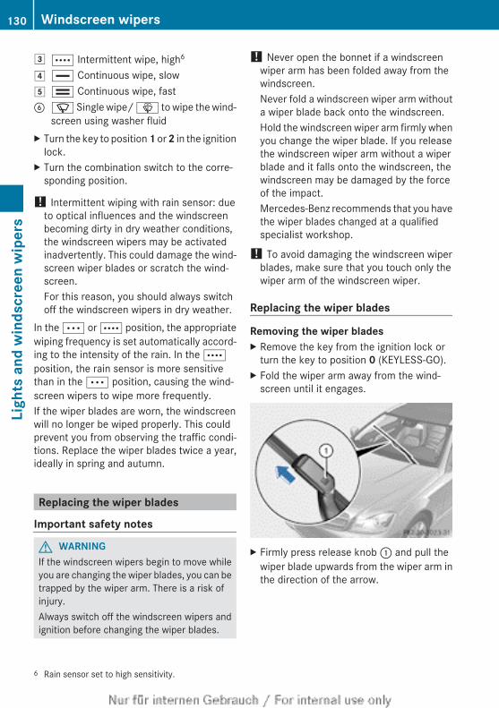
3 Å Intermittent wipe, high6
4 ° Continuous wipe, slow5 ¯ Continuous wipe, fastB í Single wipe/ î to wipe the wind-
screen using washer fluidX Turn the key to position 1 or 2 in the ignition
lock.X Turn the combination switch to the corre-
sponding position.
! Intermittent wiping with rain sensor: dueto optical influences and the windscreenbecoming dirty in dry weather conditions,the windscreen wipers may be activatedinadvertently. This could damage the wind-screen wiper blades or scratch the wind-screen.For this reason, you should always switchoff the windscreen wipers in dry weather.
In the Ä or Å position, the appropriatewiping frequency is set automatically accord-ing to the intensity of the rain. In the Åposition, the rain sensor is more sensitivethan in the Ä position, causing the wind-screen wipers to wipe more frequently.If the wiper blades are worn, the windscreenwill no longer be wiped properly. This couldprevent you from observing the traffic condi-tions. Replace the wiper blades twice a year,ideally in spring and autumn.
Replacing the wiper blades
Important safety notes
G WARNINGIf the windscreen wipers begin to move whileyou are changing the wiper blades, you can betrapped by the wiper arm. There is a risk ofinjury.Always switch off the windscreen wipers andignition before changing the wiper blades.
! Never open the bonnet if a windscreenwiper arm has been folded away from thewindscreen.Never fold a windscreen wiper arm withouta wiper blade back onto the windscreen.Hold the windscreen wiper arm firmly whenyou change the wiper blade. If you releasethe windscreen wiper arm without a wiperblade and it falls onto the windscreen, thewindscreen may be damaged by the forceof the impact.Mercedes-Benz recommends that you havethe wiper blades changed at a qualifiedspecialist workshop.
! To avoid damaging the windscreen wiperblades, make sure that you touch only thewiper arm of the windscreen wiper.
Replacing the wiper blades
Removing the wiper bladesX Remove the key from the ignition lock or
turn the key to position 0 (KEYLESS-GO).X Fold the wiper arm away from the wind-
screen until it engages.
X Firmly press release knob : and pull thewiper blade upwards from the wiper arm inthe direction of the arrow.
6 Rain sensor set to high sensitivity.
130 Windscreen wipersLi
ghts
and
win
dscr
een
wip
ers
Fitting the wiper bladesX Position the new wiper blade in the retainer
on the wiper arm and slide it into place inthe opposite direction to the arrow.The wiper blade audibly engages.
X Make sure that wiper blade is seated cor-rectly.
X Fold the wiper arm back onto the wind-screen.
Windscreen wipers 131
Ligh
ts a
nd w
inds
cree
n w
iper
s
Z
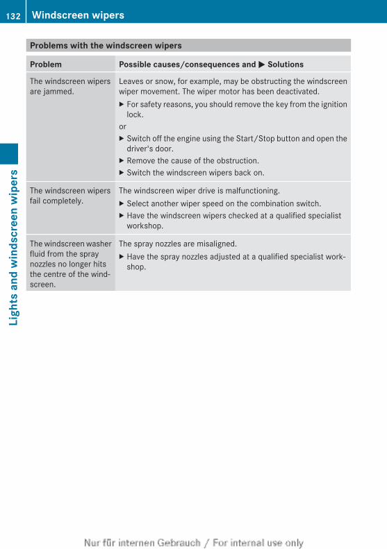
Problems with the windscreen wipers
Problem Possible causes/consequences and M Solutions
The windscreen wipersare jammed.
Leaves or snow, for example, may be obstructing the windscreenwiper movement. The wiper motor has been deactivated.X For safety reasons, you should remove the key from the ignition
lock.orX Switch off the engine using the Start/Stop button and open the
driver's door.X Remove the cause of the obstruction.X Switch the windscreen wipers back on.
The windscreen wipersfail completely.
The windscreen wiper drive is malfunctioning.X Select another wiper speed on the combination switch.X Have the windscreen wipers checked at a qualified specialist
workshop.
The windscreen washerfluid from the spraynozzles no longer hitsthe centre of the wind-screen.
The spray nozzles are misaligned.X Have the spray nozzles adjusted at a qualified specialist work-
shop.
132 Windscreen wipersLi
ghts
and
win
dscr
een
wip
ers
Useful information ............................ 134Overview of climate control sys-tems ................................................... 134Operating the climate control sys-tem ..................................................... 136Adjusting the air vents ..................... 145
133
Clim
ate
cont
rol
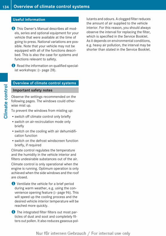
Useful information
i This Owner's Manual describes all mod-els, series and optional equipment for yourvehicle that were available at the time ofgoing to press. National variations are pos-sible. Note that your vehicle may not beequipped with all of the functions descri-bed. This is also the case for systems andfunctions relevant to safety.
i Read the information on qualified special-ist workshops: (Y page 28).
Overview of climate control systems
Important safety notesObserve the settings recommended on thefollowing pages. The windows could other-wise mist up.To prevent the windows from misting up:Rswitch off climate control only brieflyRswitch on air-recirculation mode only
brieflyRswitch on the cooling with air dehumidifi-
cation functionRswitch on the defrost windscreen function
briefly, if requiredClimate control regulates the temperatureand the humidity in the vehicle interior andfilters undesirable substances out of the air.Climate control is only operational when theengine is running. Optimum operation is onlyachieved when the side windows and the roofare closed.
i Ventilate the vehicle for a brief periodduring warm weather, e.g. using the con-venience opening feature (Y page 96). Thiswill speed up the cooling process and thedesired vehicle interior temperature will bereached more quickly.
i The integrated filter filters out most par-ticles of dust and soot and completely fil-ters out pollen. It also reduces gaseous pol-
lutants and odours. A clogged filter reducesthe amount of air supplied to the vehicleinterior. For this reason, you should alwaysobserve the interval for replacing the filter,which is specified in the Service Booklet.As it depends on environmental conditions,e.g. heavy air pollution, the interval may beshorter than stated in the Service Booklet.
134 Overview of climate control systemsCl
imat
e co
ntro
l
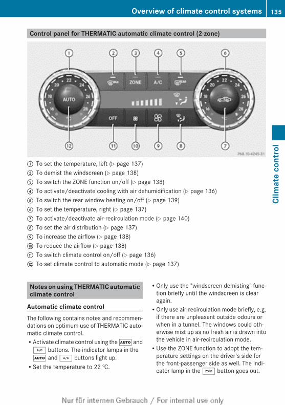
Control panel for THERMATIC automatic climate control (2-zone)
: To set the temperature, left (Y page 137); To demist the windscreen (Y page 138)= To switch the ZONE function on/off (Y page 138)? To activate/deactivate cooling with air dehumidification (Y page 136)A To switch the rear window heating on/off (Y page 139)B To set the temperature, right (Y page 137)C To activate/deactivate air-recirculation mode (Y page 140)D To set the air distribution (Y page 137)E To increase the airflow (Y page 138)F To reduce the airflow (Y page 138)G To switch climate control on/off (Y page 136)H To set climate control to automatic mode (Y page 137)
Notes on using THERMATIC automaticclimate control
Automatic climate controlThe following contains notes and recommen-dations on optimum use of THERMATIC auto-matic climate control.RActivate climate control using the à and¿ buttons. The indicator lamps in theà and ¿ buttons light up.RSet the temperature to 22 †.
ROnly use the "windscreen demisting" func-tion briefly until the windscreen is clearagain.ROnly use air-recirculation mode briefly, e.g.
if there are unpleasant outside odours orwhen in a tunnel. The windows could oth-erwise mist up as no fresh air is drawn intothe vehicle in air-recirculation mode.RUse the ZONE function to adopt the tem-
perature settings on the driver's side forthe front-passenger side as well. The indi-cator lamp in the á button goes out.
Overview of climate control systems 135
Clim
ate
cont
rol
ECO start/stop functionDuring automatic engine switch-off in theECO start/stop function, the climate controlsystem only operates at a reduced capacity.If you require the full climate control output,you can switch off the ECO start/stop func-tion by pressing the ECO button(Y page 154).
i The ECO start/stop function is not avail-able on AMG vehicles.
Operating the climate control system
Switching climate control on/off
General notesWhen the climate control is switched off, theair supply and air circulation are alsoswitched off. The windows could mist up.Therefore, only switch off climate controlbriefly.
i Switch on climate control primarily usingthe à button (Y page 137).
Activating/deactivatingX Turn the key to position 2 in the ignition
lock (Y page 149).X To switch on: press the à button.
The indicator lamp in the à button lightsup. Airflow and air distribution are set toautomatic mode.
orX Press the ^ button.
The indicator lamp in the ̂ button goesout. The previous settings are reactivated.
X To switch off: press the ^ button.The indicator lamp in the ̂ button lightsup.
Activating/deactivating the coolingwith air dehumidification function
General notesIf you deactivate the "Cooling with air-dehu-midification" function, the air inside the vehi-cle will not be cooled. The air inside the vehi-cle will also not be dehumidified. The win-dows can mist up more quickly. Therefore,only switch off cooling with air dehumidifica-tion for a short period.The "Cooling with air dehumidification" func-tion is only available when the engine is run-ning. The air inside the vehicle is cooled anddehumidified according to the temperatureselected.Condensation may drip from the underside ofthe vehicle when cooling mode is active. Thisis normal and not a sign that there is a mal-function.
Activating/deactivatingX To activate: press the ¿ button.
The indicator lamp in the ¿ button lightsup.
i In vehicles with auxiliary heating, one ofthe indicator lamps on the auxiliary heatingbutton lights up when the "cooling with airdehumidification" function is activated.
X To deactivate: press the ¿ button.The indicator lamp in the ¿ button goesout. The "Cooling with air dehumidification"function has a delayed switch-off feature.
136 Operating the climate control systemCl
imat
e co
ntro
l
Problems with the "Cooling with air dehumidification" function
Problem Possible causes/consequences and M Solutions
The indicator lamp inthe ¿ buttonflashes three times orremains off. The cool-ing with air dehumidifi-cation system cannotbe switched on.
Cooling with air dehumidification has been deactivated due to amalfunction.X Visit a qualified specialist workshop.
Setting climate control to automaticmode
General notesIn automatic mode, the set temperature ismaintained automatically at a constant level.The system automatically regulates the tem-perature of the dispensed air, the airflow andthe air distribution.The automatic mode functions optimallywhen the "Cooling with air dehumidification"function is activated. If desired, cooling withair dehumidification can be deactivated.If you deactivate the "Cooling with air-dehu-midification" function, the air inside the vehi-cle will not be cooled. The air inside the vehi-cle will also not be dehumidified. The win-dows can mist up more quickly. Therefore,only switch off cooling with air dehumidifica-tion for a short period.
Activating/switchingX Turn the key to position 2 in the ignition
lock (Y page 149).X Set the desired temperature.X To activate: press the à button.
The indicator lamp in the à button lightsup. Automatic air distribution and airfloware activated.
X To switch to manual mode: press the_ button.
orX Press the K or I button.
The indicator lamp in the à button goesout. Automatic air distribution and airfloware deactivated.
Setting the temperatureDifferent temperatures can be set for thedriver's and front-passenger sides.X Turn the key to position 2 in the ignition
lock (Y page 149).X To increase/reduce: turn controls : andB clockwise or anti-clockwise(Y page 135).Only change the temperature setting insmall increments. Start at 22 †.
Setting the air distribution
Air distribution settingsP Directs the airflow through the centre
and side air ventsO Directs the airflow through the foot-
well air ventsS Directs the airflow through the centre
and side air vents as well as the foot-well air vents
Operating the climate control system 137
Clim
ate
cont
rol
¯ Directs the airflow through the demis-ter vents
b Directs the airflow through the demis-ter, centre and side air vents
a Directs the airflow through the foot-well and demister vents
_ Directs the airflow through the demis-ter vents, the centre and side air ventsas well as the footwell air vents
i Regardless of the air distribution setting,airflow is always directed through the sideair vents. The side air vents can only beclosed when the controls on the side airvents are turned downwards.
AdjustingX Turn the key to position 2 in the ignition
lock (Y page 149).X Press the _ button repeatedly until the
desired symbol appears in the display.The indicator lamp in the à button goesout. Automatic control is deactivated andthe air distribution is controlled accordingto the selected setting.
Setting the airflowX Turn the key to position 2 in the ignition
lock (Y page 149).X To increase/reduce: press the K orI button.
If the battery is not sufficiently charged,blower output may be reduced. As soon asthe battery is sufficiently charged, full bloweroutput will be available.
Switching the ZONE function on/offX To switch on: press the á button.
The indicator lamp in the á button lightsup.
The temperature setting for the driver'sside is not adopted for the front-passengerside.
When the buttons for temperature, airflow orair distribution are pressed, the temperaturesetting on the driver's side is not adopted forthe other climate control zones.X To switch off: press the á button.
The indicator lamp in the á button goesout.The temperature setting for the driver'sside is adopted for the front-passengerside.
Demisting the windscreenYou can use this function to defrost the wind-screen or to demist the inside of the wind-screen and the side windows.
i You should only select the "windscreendemisting" function until the windscreen isclear again.
X Turn the key to position 2 in the ignitionlock (Y page 149).
X To activate: press the ¬ button.The indicator lamp in the ¬ button lightsup.The climate control system switches to thefollowing functions:Rhigh airflowRhigh temperatureRair distribution to the windscreen and
front side windowsRair-recirculation mode off
If the battery is not sufficiently charged,blower output may be reduced. As soon asthe battery is sufficiently charged, full bloweroutput will be available.X To deactivate: press the ¬ button.
The indicator lamp in the ¬ button goesout. The previous settings are reactivated.
138 Operating the climate control systemCl
imat
e co
ntro
l
Air-recirculation mode remains deactiva-ted.
orX Press the à button.
The indicator lamp in the ¬ button goesout. Airflow and air distribution are set toautomatic mode.
orX Turn temperature control : or B clock-
wise or anti-clockwise (Y page 135).orX Press the K or I button.
Demisting the windows
Windows misted up on the insideX Activate the ¿ cooling with air dehu-
midification function.X Activate automatic mode Ã.X Adjust the side air vents so that the heated
air is directed towards the side windows.X If the windows continue to mist up, activate
the ¬ "Windscreen demisting" function.
i You should only select this setting untilthe windscreen is clear again.
Windows misted up on the outsideX Activate the windscreen wipers.X Press the _ button repeatedly until theO or P symbol appears in the dis-play.
X Adjust the side air vents so that no air isdirected towards the side windows.
Rear window heating
General notesThe rear window heating has a high currentdraw. You should therefore switch it off assoon as the window is clear. It otherwise
switches off automatically after severalminutes.If the battery voltage is too low, the rear win-dow heating may switch off.
Activating/deactivatingX Turn the key to position 2 in the ignition
lock (Y page 149).X Press the ¤ button.
The indicator lamp in the ¤ button lightsup or goes out.
Operating the climate control system 139
Clim
ate
cont
rol
Problems with the rear window heating
Problem Possible causes/consequences and M Solutions
The rear window heat-ing has switched offprematurely or cannotbe activated.
The battery has not been sufficiently charged.X Switch off any consumers that are not required, e.g. reading
lamps, interior lighting or the seat heating.When the battery is sufficiently charged, the rear window heat-ing can be activated again.
Activating/deactivating air-recircula-tion mode
General notesYou can deactivate the flow of fresh air ifunpleasant odours are entering the vehiclefrom outside. The air already inside the vehi-cle will then be recirculated.If you switch on air-recirculation mode, thewindows can mist up more quickly, in partic-ular at low temperatures. Only use air-recir-culation mode briefly to prevent the windowsmisting up.The operation of air-recirculation mode is thesame for all control panels.
Activating/deactivatingX Turn the key to position 2 in the ignition
lock (Y page 149).X To activate: press the g button.
The indicator lamp in the g button lightsup.
i Air-recirculation mode is activated auto-matically at high outside temperatures.When air-recirculation mode is activatedautomatically, the indicator lamp in theg button is not lit.Outside air is added after about30 minutes.
X To deactivate: press the g button.The indicator lamp in the g button goesout.
Convenience opening/closing usingthe air-recirculation button
G WARNINGWhen the convenience closing feature is oper-ating, parts of the body could become trappedin the closing area of the side window and thesliding sunroof. There is a risk of injury.Observe the complete closing procedurewhen the convenience closing feature is oper-ating. When closing make sure that no partsof the body are in the closing area.
G WARNINGDuring convenience opening parts of the bodycould be drawn in or become trappedbetween the side window and window frame.There is a risk of injury.When opening, make sure that nobody istouching the side window. If someonebecomes trapped, press the W switchimmediately to open/close the side windowin the door. The side window stops. To con-tinue closing the side window, pull on theW switch.
X Convenience closing feature: press andhold the g button until the side win-dows and the panorama sliding sunroof areclosed.The indicator lamp in the g button lightsup. Air-recirculation mode is activated.
140 Operating the climate control systemCl
imat
e co
ntro
l
If parts of the body are in the closing areaduring convenience closing, proceed as fol-lows:X Press the W button for opening/closing
the side windows.The side window stops.
X To then open the side window, press theW button again.
X Press the 3 switch for opening/closingthe panorama sliding sunroof.The panorama sliding sunroof stops.
X To then open the panorama sliding sunroof,pull back on the 3 switch.
i If the sliding sunroof is raised and closes,press the 3 switch, to stop the slidingsunroof. Do not pull back on the 3switch afterwards. The sliding sunroofcloses before it opens.
i Notes on the automatic reversing func-tion for:Rthe side window (Y page 95)Rthe panorama sliding sunroof
(Y page 98)X Convenience opening feature: press and
hold the g button until the side win-dows and the panorama sliding sunroofhave opened. The side windows and thepanorama sliding sunroof move back totheir original position.The indicator lamp in the g button goesout. Air-recirculation mode is deactivated.
i If you open the side windows or the pan-orama sliding sunroof manually after clos-ing with the convenience closing feature,they will remain in this position whenopened using the convenience opening fea-ture.
Auxiliary heating
Important safety notes
G DANGERIf the exhaust pipe is blocked or sufficientventilation is not possible, toxic exhaustfumes can enter the vehicle, especially car-bon monoxide. This is the case, e.g. inenclosed spaces, or if the vehicle is stuck insnow. There is a risk of fatal injuries.You should switch off the auxiliary heating inenclosed spaces which do not have an extrac-tion system, e.g. a garage. If the vehicle isstuck in snow and you must leave the auxiliaryheating running, keep the exhaust pipe andthe area around the vehicle clear of snow. Toguarantee a sufficient supply of fresh air, opena window on the side of the vehicle away fromthe wind.
G WARNINGWhen the auxiliary heating is switched on,parts of the vehicle can become very hot.Flammable material such as leaves, grass ortwigs may ignite if they come into contact withhot parts of the exhaust system for extendedperiods. There is a risk of fire.When the auxiliary heating is switched on,make sure that no flammable material cancome into contact with hot vehicle compo-nents.
! Operating the auxiliary heating/ventila-tion draws on the vehicle battery. After youhave heated or ventilated the vehicle amaximum of two times, drive for a longerdistance.
i Switch the auxiliary heating on regularlyonce a month for about ten minutes.
The auxiliary heating heats the air in the vehi-cle interior to the set temperature. Thisoccurs without using the heat of the runningengine. The auxiliary heating is operateddirectly using the vehicle's fuel. For this rea-son, the tank content must be at least at
Operating the climate control system 141
Clim
ate
cont
rol
Z
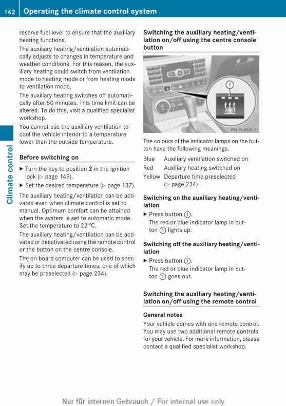
reserve fuel level to ensure that the auxiliaryheating functions.The auxiliary heating/ventilation automati-cally adjusts to changes in temperature andweather conditions. For this reason, the aux-iliary heating could switch from ventilationmode to heating mode or from heating modeto ventilation mode.The auxiliary heating switches off automati-cally after 50 minutes. This time limit can bealtered. To do this, visit a qualified specialistworkshop.You cannot use the auxiliary ventilation tocool the vehicle interior to a temperaturelower than the outside temperature.
Before switching onX Turn the key to position 2 in the ignition
lock (Y page 149).X Set the desired temperature (Y page 137).The auxiliary heating/ventilation can be acti-vated even when climate control is set tomanual. Optimum comfort can be attainedwhen the system is set to automatic mode.Set the temperature to 22 †.The auxiliary heating/ventilation can be acti-vated or deactivated using the remote controlor the button on the centre console.The on-board computer can be used to spec-ify up to three departure times, one of whichmay be preselected (Y page 234).
Switching the auxiliary heating/venti-lation on/off using the centre consolebutton
The colours of the indicator lamps on the but-ton have the following meanings:Blue Auxiliary ventilation switched onRed Auxiliary heating switched onYellow Departure time preselected
(Y page 234)
Switching on the auxiliary heating/venti-lationX Press button :.
The red or blue indicator lamp in but-ton : lights up.
Switching off the auxiliary heating/venti-lationX Press button :.
The red or blue indicator lamp in but-ton : goes out.
Switching the auxiliary heating/venti-lation on/off using the remote control
General notesYour vehicle comes with one remote control.You may use two additional remote controlsfor your vehicle. For more information, pleasecontact a qualified specialist workshop.
142 Operating the climate control systemCl
imat
e co
ntro
l
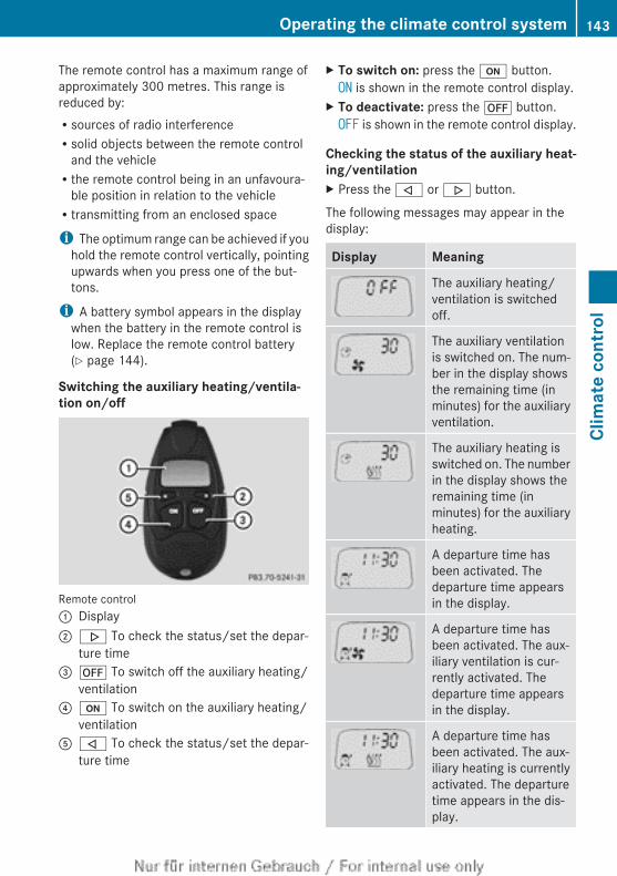
The remote control has a maximum range ofapproximately 300 metres. This range isreduced by:Rsources of radio interferenceRsolid objects between the remote control
and the vehicleRthe remote control being in an unfavoura-
ble position in relation to the vehicleRtransmitting from an enclosed space
i The optimum range can be achieved if youhold the remote control vertically, pointingupwards when you press one of the but-tons.
i A battery symbol appears in the displaywhen the battery in the remote control islow. Replace the remote control battery(Y page 144).
Switching the auxiliary heating/ventila-tion on/off
Remote control: Display; . To check the status/set the depar-
ture time= ^ To switch off the auxiliary heating/
ventilation? u To switch on the auxiliary heating/
ventilationA , To check the status/set the depar-
ture time
X To switch on: press the u button.ON is shown in the remote control display.
X To deactivate: press the ^ button.OFF is shown in the remote control display.
Checking the status of the auxiliary heat-ing/ventilationX Press the , or . button.
The following messages may appear in thedisplay:
Display Meaning
The auxiliary heating/ventilation is switchedoff.
The auxiliary ventilationis switched on. The num-ber in the display showsthe remaining time (inminutes) for the auxiliaryventilation.
The auxiliary heating isswitched on. The numberin the display shows theremaining time (inminutes) for the auxiliaryheating.
A departure time hasbeen activated. Thedeparture time appearsin the display.
A departure time hasbeen activated. The aux-iliary ventilation is cur-rently activated. Thedeparture time appearsin the display.
A departure time hasbeen activated. The aux-iliary heating is currentlyactivated. The departuretime appears in the dis-play.
Operating the climate control system 143
Clim
ate
cont
rol
Z
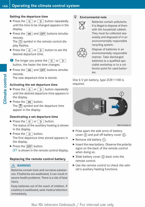
Setting the departure timeX Press the , or . button repeatedly
until the time to be changed appears in thedisplay.
X Press the u and ^ buttons simulta-neously.The Î symbol in the remote control dis-play flashes.
X Press the , or . button to set thedesired departure time.
i The longer you press the , or .button, the faster the time changes.
X Press the u and ^ buttons simulta-neously.The new departure time is stored.
Activating the set departure timeX Press the , or . button repeatedly
until the desired departure time appears inthe display.
X Press the u button.The Í symbol and the departure timeappear in the display.
Deactivating a set departure timeX Press the , or . button.
The status of the auxiliary heating is shownin the display.
X Press the . button.The first departure time stored appears inthe display.
X Press the ^ button.OFF is shown in the remote control display.
Replacing the remote control battery
G WARNINGBatteries contain toxic and corrosive substan-ces. If batteries are swallowed, it can result insevere health problems. There is a risk of fatalinjury.Keep batteries out of the reach of children. Ifa battery is swallowed, seek medical attentionimmediately.
H Environmental noteBatteries contain pollutants.It is illegal to dispose of themwith the household rubbish.They must be collected sep-arately and disposed of in anenvironmentally responsiblerecycling system.Dispose of batteries in anenvironmentally responsiblemanner. Take dischargedbatteries to a qualified spe-cialist workshop or to a col-lection point for used batter-ies.
One 6 V pin battery, type 2CR11108 isrequired.
X Prise apart the side arms of batterycover ; and pull off battery cover ;.
X Remove old battery :.X Insert the new battery. Observe the polarity
signs on the back of the remote controlwhen doing so.
X Slide battery cover ; back onto theremote control.
X Use the remote control to check the vehi-cle's auxiliary heating functions.
144 Operating the climate control systemCl
imat
e co
ntro
l
Problems with the auxiliary heating/ventilation
Display messages Possible causes/consequences and M Solutions
FAIL The starter battery is not charged sufficiently or the system isfaulty.X Charge the starter battery.X Make another attempt to switch on the auxiliary heating using
the remote control.X Have the auxiliary heating checked at a qualified specialist
workshop.
$FAIL
The signal transmission between the transmitter and the vehicleis faulty.X Change your position in relation to the vehicle, moving closer if
necessary.X Make another attempt to switch the auxiliary heating on or off
using the remote control.
©FAIL
There is insufficient fuel in the fuel tank. This means that the tankcontent is below reserve fuel level.X Refuel at the nearest filling station.X Make another attempt to switch on the auxiliary heating using
the remote control.
The auxiliary heating is faulty.X Have the auxiliary heating checked at a qualified specialist
workshop.
Adjusting the air vents
Important safety notes
G WARNINGVery hot or very cold air can flow from the airvents. This could result in burns or frostbite inthe immediate vicinity of the air vents. Thereis a risk of injury.Make sure that all vehicle occupants alwaysmaintain a sufficient distance to the air out-lets. If necessary, redirect the airflow toanother area of the vehicle interior.
In order to ensure the direct flow of fresh airthrough the air vents into the vehicle interior,please observe the following notes:Rnever cover the vents or ventilation grilles
in the vehicle interior.
i For virtually draught-free ventilation,adjust the sliders of the air vents to thecentre position.
Adjusting the air vents 145
Clim
ate
cont
rol
Z
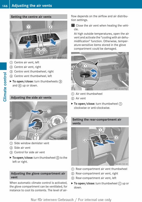
Setting the centre air vents
: Centre air vent, left; Centre air vent, right= Centre vent thumbwheel, right? Centre vent thumbwheel, leftX To open/close: turn thumbwheels =
and ? up or down.
Adjusting the side air vents
: Side window demister vent; Side air vent= Control for side air ventX To open/close: turn thumbwheel = to the
left or right.
Adjusting the glove compartment airvent
When automatic climate control is activated,the glove compartment can be ventilated, forinstance to cool its contents. The level of air-
flow depends on the airflow and air distribu-tion settings.
! Close the air vent when heating the vehi-cle.At high outside temperatures, open the airvent and activate the "cooling with air dehu-midification" function. Otherwise, temper-ature-sensitive items stored in the glovecompartment could be damaged.
: Air vent thumbwheel; Air ventX To open/close: turn thumbwheel :
clockwise or anti-clockwise.
Setting the rear-compartment airvents
: Rear-compartment air vent thumbwheel; Rear-compartment air vent, right= Rear-compartment air vent, leftX To open/close: turn thumbwheel : up or
down.
146 Adjusting the air ventsCl
imat
e co
ntro
l
Useful information ............................ 148Running-in notes ............................... 148Driving ............................................... 148Manual transmission ........................ 157Automatic transmission ................... 158Refuelling ........................................... 165Parking ............................................... 169Driving tips ........................................ 171Driving systems ................................ 174Towing a trailer ................................. 209
147
Driv
ing
and
park
ing
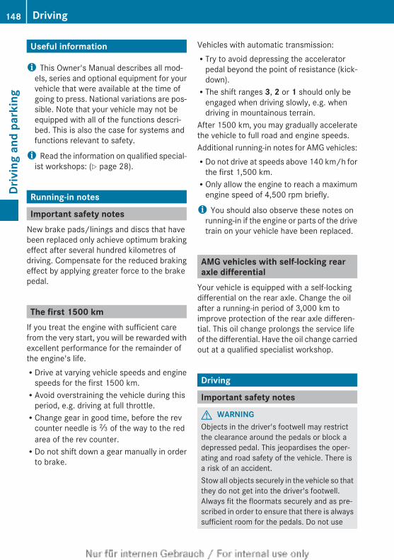
Useful information
i This Owner's Manual describes all mod-els, series and optional equipment for yourvehicle that were available at the time ofgoing to press. National variations are pos-sible. Note that your vehicle may not beequipped with all of the functions descri-bed. This is also the case for systems andfunctions relevant to safety.
i Read the information on qualified special-ist workshops: (Y page 28).
Running-in notes
Important safety notesNew brake pads/linings and discs that havebeen replaced only achieve optimum brakingeffect after several hundred kilometres ofdriving. Compensate for the reduced brakingeffect by applying greater force to the brakepedal.
The first 1500 kmIf you treat the engine with sufficient carefrom the very start, you will be rewarded withexcellent performance for the remainder ofthe engine's life.RDrive at varying vehicle speeds and engine
speeds for the first 1500 km.RAvoid overstraining the vehicle during this
period, e.g. driving at full throttle.RChange gear in good time, before the rev
counter needle is Ô of the way to the redarea of the rev counter.RDo not shift down a gear manually in order
to brake.
Vehicles with automatic transmission:RTry to avoid depressing the accelerator
pedal beyond the point of resistance (kick-down).RThe shift ranges 3, 2 or 1 should only be
engaged when driving slowly, e.g. whendriving in mountainous terrain.
After 1500 km, you may gradually acceleratethe vehicle to full road and engine speeds.Additional running-in notes for AMG vehicles:RDo not drive at speeds above 140 km/h for
the first 1,500 km.ROnly allow the engine to reach a maximum
engine speed of 4,500 rpm briefly.
i You should also observe these notes onrunning-in if the engine or parts of the drivetrain on your vehicle have been replaced.
AMG vehicles with self-locking rearaxle differential
Your vehicle is equipped with a self-lockingdifferential on the rear axle. Change the oilafter a running-in period of 3,000 km toimprove protection of the rear axle differen-tial. This oil change prolongs the service lifeof the differential. Have the oil change carriedout at a qualified specialist workshop.
Driving
Important safety notes
G WARNINGObjects in the driver's footwell may restrictthe clearance around the pedals or block adepressed pedal. This jeopardises the oper-ating and road safety of the vehicle. There isa risk of an accident.Stow all objects securely in the vehicle so thatthey do not get into the driver's footwell.Always fit the floormats securely and as pre-scribed in order to ensure that there is alwayssufficient room for the pedals. Do not use
148 DrivingDr
ivin
g an
d pa
rkin
g
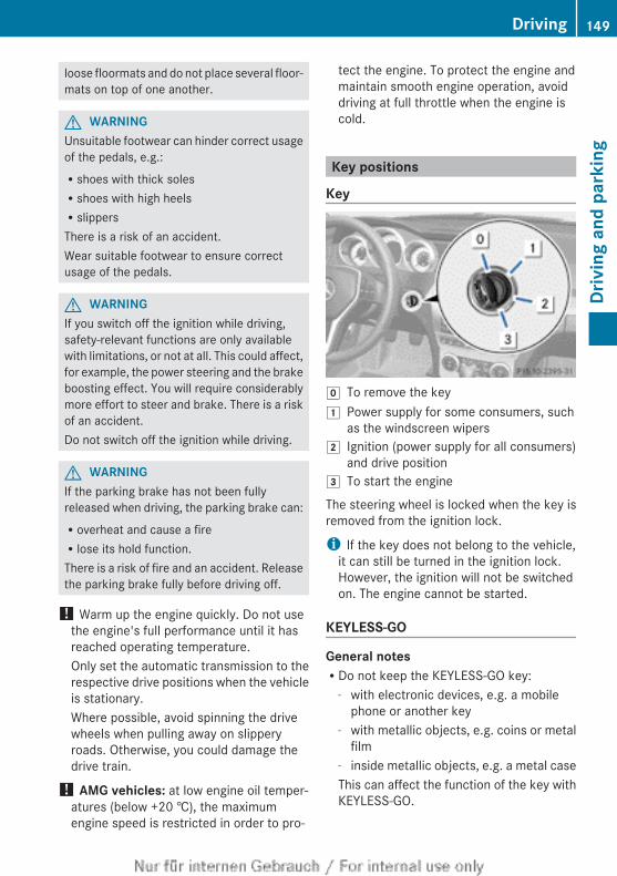
loose floormats and do not place several floor-mats on top of one another.
G WARNINGUnsuitable footwear can hinder correct usageof the pedals, e.g.:Rshoes with thick solesRshoes with high heelsRslippersThere is a risk of an accident.Wear suitable footwear to ensure correctusage of the pedals.
G WARNINGIf you switch off the ignition while driving,safety-relevant functions are only availablewith limitations, or not at all. This could affect,for example, the power steering and the brakeboosting effect. You will require considerablymore effort to steer and brake. There is a riskof an accident.Do not switch off the ignition while driving.
G WARNINGIf the parking brake has not been fullyreleased when driving, the parking brake can:Roverheat and cause a fireRlose its hold function.There is a risk of fire and an accident. Releasethe parking brake fully before driving off.
! Warm up the engine quickly. Do not usethe engine's full performance until it hasreached operating temperature.Only set the automatic transmission to therespective drive positions when the vehicleis stationary.Where possible, avoid spinning the drivewheels when pulling away on slipperyroads. Otherwise, you could damage thedrive train.
! AMG vehicles: at low engine oil temper-atures (below +20 †), the maximumengine speed is restricted in order to pro-
tect the engine. To protect the engine andmaintain smooth engine operation, avoiddriving at full throttle when the engine iscold.
Key positions
Key
g To remove the key1 Power supply for some consumers, such
as the windscreen wipers2 Ignition (power supply for all consumers)
and drive position3 To start the engine
The steering wheel is locked when the key isremoved from the ignition lock.
i If the key does not belong to the vehicle,it can still be turned in the ignition lock.However, the ignition will not be switchedon. The engine cannot be started.
KEYLESS-GO
General notesRDo not keep the KEYLESS-GO key:
- with electronic devices, e.g. a mobilephone or another key
- with metallic objects, e.g. coins or metalfilm
- inside metallic objects, e.g. a metal caseThis can affect the function of the key withKEYLESS-GO.
Driving 149
Driv
ing
and
park
ing
Z
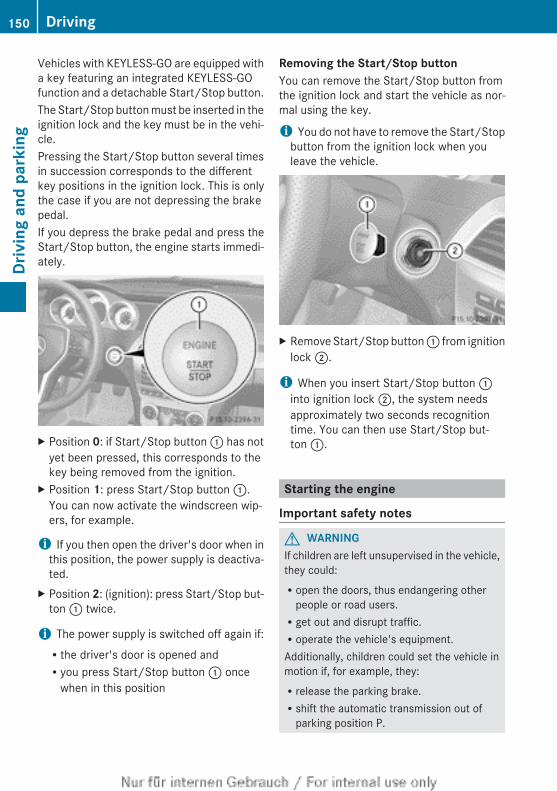
Vehicles with KEYLESS-GO are equipped witha key featuring an integrated KEYLESS-GOfunction and a detachable Start/Stop button.The Start/Stop button must be inserted in theignition lock and the key must be in the vehi-cle.Pressing the Start/Stop button several timesin succession corresponds to the differentkey positions in the ignition lock. This is onlythe case if you are not depressing the brakepedal.If you depress the brake pedal and press theStart/Stop button, the engine starts immedi-ately.
X Position 0: if Start/Stop button : has notyet been pressed, this corresponds to thekey being removed from the ignition.
X Position 1: press Start/Stop button :.You can now activate the windscreen wip-ers, for example.
i If you then open the driver's door when inthis position, the power supply is deactiva-ted.
X Position 2: (ignition): press Start/Stop but-ton : twice.
i The power supply is switched off again if:Rthe driver's door is opened andRyou press Start/Stop button : once
when in this position
Removing the Start/Stop buttonYou can remove the Start/Stop button fromthe ignition lock and start the vehicle as nor-mal using the key.
i You do not have to remove the Start/Stopbutton from the ignition lock when youleave the vehicle.
X Remove Start/Stop button : from ignitionlock ;.
i When you insert Start/Stop button :into ignition lock ;, the system needsapproximately two seconds recognitiontime. You can then use Start/Stop but-ton :.
Starting the engine
Important safety notes
G WARNINGIf children are left unsupervised in the vehicle,they could:Ropen the doors, thus endangering other
people or road users.Rget out and disrupt traffic.Roperate the vehicle's equipment.Additionally, children could set the vehicle inmotion if, for example, they:Rrelease the parking brake.Rshift the automatic transmission out of
parking position P.
150 DrivingDr
ivin
g an
d pa
rkin
g
Rshift the manual transmission into neutral.Rstart the engine.There is a risk of an accident and injury.When leaving the vehicle, always take the keywith you and lock the vehicle. Never leavechildren or animals unattended in the vehicle.Always keep the key out of reach of children.
G WARNINGCombustion engines emit poisonous exhaustgases such as carbon monoxide. Inhalingthese exhaust gases leads to poisoning. Thereis a risk of fatal injury. Therefore never leavethe engine running in enclosed spaces with-out sufficient ventilation.
G WARNINGFlammable materials introduced throughenvironmental influence or by animals canignite if in contact with the exhaust system orparts of the engine that heat up. There is a riskof fire.Carry out regular checks to make sure thatthere are no flammable foreign materials inthe engine compartment or in the exhaustsystem.
! Do not depress the accelerator pedalwhen starting the engine.
General notesi Vehicles with a petrol engine: the cat-
alytic converter is preheated for up toapproximately 30 seconds after a coldstart. The sound of the engine may changeduring this time.
Manual transmissionX Depress the brake pedal and keep it
depressed.X Fully depress the clutch pedal.X Shift to neutral N.
i You can only start the engine when theclutch pedal is fully depressed.
Automatic transmissionX Shift the transmission to position P.
The transmission position display in themultifunction display shows P.
i You can also start the engine when thetransmission is in position N.
Starting procedure with the keyi To start the engine using the key instead
of KEYLESS-GO, pull the Start/Stop buttonout of the ignition lock.
X To start a petrol engine: turn the key toposition 3 in the ignition lock(Y page 149) and release it as soon as theengine is running.
X To start a diesel engine: turn the key toposition 2 in the ignition lock(Y page 149).The % preglow indicator lamp in theinstrument cluster lights up.
X When the % preglow indicator lampgoes out, turn the key to position3(Y page 149) and release it as soon as theengine is running.
i You can start the engine without preglowif the engine is warm.
Using KEYLESS-GO to start the engineYou can start the engine if a valid key with theintegrated KEYLESS-GO function is in thevehicle. Always take the key with you whenleaving the vehicle, even if you only leave itfor a short time. Pay attention to the impor-tant safety notes.
i The Start/Stop button can be used tostart the vehicle manually without insertingthe key into the ignition lock. The key mustbe in the vehicle and the Start/Stop buttonmust be inserted in the ignition lock. Thismode for starting the engine operates inde-pendently of the ECO start/stop automaticengine start function.
Driving 151
Driv
ing
and
park
ing
Z
X Depress the brake pedal and keep itdepressed.
X To start a petrol engine: press the Start/Stop button once (Y page 149).The engine starts.
X To start a diesel engine: press the Start/Stop button once (Y page 149).Preglow is activated and the engine starts.
Pulling away
Manual transmissionX Depress the brake pedal and keep it
depressed.X Fully depress the clutch pedal.X Shift to either first gear or reverse gear R.X Release the parking brake (Y page 170).X Release the brake pedal.X Slowly release the clutch pedal and gently
depress the accelerator pedal.
! Change gear in good time and avoid spin-ning the wheels. Otherwise, you could dam-age the vehicle.
i Follow the shift recommendations in themultifunction display for an economicaldriving style (Y page 158).
i The vehicle locks centrally once you havepulled away. The locking knobs in the doorsdrop down.You can open the doors from the inside atany time.You can also deactivate the automatic doorlock (Y page 234).
Automatic transmission
G WARNINGIf the engine speed is above the idling speedand you engage transmission position D orR, the vehicle could pull away suddenly. Thereis a risk of an accident.
When engaging transmission position D or R,always firmly depress the brake pedal and donot simultaneously accelerate.
i It is only possible to shift the transmissionfrom position P to the desired position ifyou depress the brake pedal. Only then isthe selector lever lock released.
X Depress the brake pedal and keep itdepressed.
X Shift the transmission to position D or R.X Release the parking brake (Y page 170).X Release the brake pedal.X Carefully depress the accelerator pedal.
i The vehicle locks centrally once you havepulled away. The locking knobs in the doorsdrop down.You can open the doors from the inside atany time.You can also deactivate the automatic lock-ing feature (Y page 234).
i Upshifts take place at higher enginespeeds after a cold start. This helps thecatalytic converter to reach its operatingtemperature more quickly.
Hill start assistHill start assist helps you when pulling awayforwards or in reverse on an uphill gradient.It holds the vehicle for a short time after youhave removed your foot from the brake pedal.This gives you enough time to move your footfrom the brake pedal to the accelerator pedaland depress it before the vehicle begins toroll.
G WARNINGAfter a short time, hill start assist will no lon-ger brake your vehicle and it could roll away.There is a risk of an accident and injury.Therefore, quickly move your foot from thebrake pedal to the accelerator pedal. Neverleave the vehicle when it is held by hill startassist.
152 DrivingDr
ivin
g an
d pa
rkin
g
X Take your foot off the brake pedal.The vehicle is then held for about a second.
X Pull away.Hill start assist is not active if:Ryou are pulling away on a level road or a
downhill gradient.Ron vehicles with automatic transmission,
the transmission is in position N.Rthe parking brake is engaged.RESP® is malfunctioning.
ECO start/stop function
IntroductionThe ECO start/stop function switches theengine off automatically if the vehicle is stop-ped under certain conditions.When pulling away again, the engine startsautomatically. The ECO start/stop functionthereby helps you to reduce the fuel con-sumption and emissions of your vehicle.
Important safety notes
G WARNINGIf the engine is switched off automatically andyou exit the vehicle, the engine is restartedautomatically. The vehicle may begin moving.There is a risk of accident and injury.If you wish to exit the vehicle, always turn offthe ignition and secure the vehicle againstrolling away.
General notesIf the ¤ symbol is shown in green in themultifunction display, the ECO start/stopfunction switches the engine off automati-cally if the vehicle stops moving.Every time you switch on the engine using thekey or the Start/Stop button, the ECO start/stop function is activated.If the ECO start/stop function has been man-ually deactivated (Y page 154) or a malfunc-
tion has caused the system to be deactivated,the ¤ symbol is not displayed.
Automatic engine switch-off
General notesThe ECO start/stop function is operationaland the ¤ symbol is displayed in green inthe multifunction display, if:Rthe indicator lamp in the ECO button is lit
greenRthe outside temperature is within the range
that is suitable for the systemRthe engine is at normal operating temper-
atureRthe set temperature for the vehicle interior
has been reachedRthe battery is sufficiently chargedRthe system detects that the windscreen is
not misted up when the air-conditioningsystem is switched onRthe bonnet is closedRthe driver's door is closed and the driver's
seat belt is fastenedIf not all conditions for automatic engineswitch-off are fulfilled, the ¤ symbol isshown in yellow.
i All of the vehicle's systems remain activewhen the engine is switched off automati-cally.
i The engine can be switched off automat-ically a maximum of four times (initial stop,then three subsequent stops) in succes-sion. The ¤ symbol is shown in yellowin the multifunction display after the enginehas been started automatically for thefourth time. When the ¤ symbol isshown in green in the multifunction display,automatic engine switch-off is again possi-ble.
Vehicles with manual transmissionThe ECO start/stop function switches off theengine automatically at low speeds.
Driving 153
Driv
ing
and
park
ing
Z
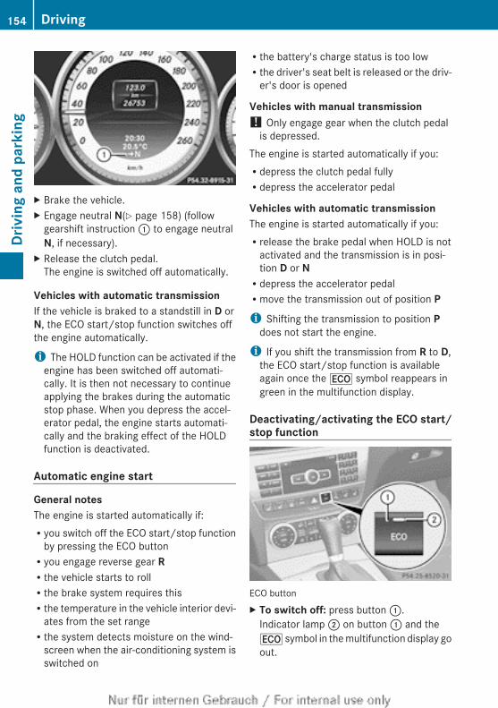
X Brake the vehicle.X Engage neutral N(Y page 158) (follow
gearshift instruction : to engage neutralN, if necessary).
X Release the clutch pedal.The engine is switched off automatically.
Vehicles with automatic transmissionIf the vehicle is braked to a standstill in D orN, the ECO start/stop function switches offthe engine automatically.
i The HOLD function can be activated if theengine has been switched off automati-cally. It is then not necessary to continueapplying the brakes during the automaticstop phase. When you depress the accel-erator pedal, the engine starts automati-cally and the braking effect of the HOLDfunction is deactivated.
Automatic engine start
General notesThe engine is started automatically if:Ryou switch off the ECO start/stop function
by pressing the ECO buttonRyou engage reverse gear RRthe vehicle starts to rollRthe brake system requires thisRthe temperature in the vehicle interior devi-
ates from the set rangeRthe system detects moisture on the wind-
screen when the air-conditioning system isswitched on
Rthe battery's charge status is too lowRthe driver's seat belt is released or the driv-
er's door is opened
Vehicles with manual transmission! Only engage gear when the clutch pedal
is depressed.The engine is started automatically if you:Rdepress the clutch pedal fullyRdepress the accelerator pedal
Vehicles with automatic transmissionThe engine is started automatically if you:Rrelease the brake pedal when HOLD is not
activated and the transmission is in posi-tion D or NRdepress the accelerator pedalRmove the transmission out of position Pi Shifting the transmission to position P
does not start the engine.
i If you shift the transmission from R to D,the ECO start/stop function is availableagain once the ¤ symbol reappears ingreen in the multifunction display.
Deactivating/activating the ECO start/stop function
ECO buttonX To switch off: press button :.
Indicator lamp ; on button : and the¤ symbol in the multifunction display goout.
154 DrivingDr
ivin
g an
d pa
rkin
g
X To switch on: press button :.Indicator lamp ; lights up.If all conditions for automatic engineswitch-off (Y page 153) are fulfilled, the¤ symbol is shown in green in the mul-tifunction display.If not all conditions for automatic engineswitch-off (Y page 153) are fulfilled, the¤ symbol is shown in yellow in the mul-tifunction display. If this is the case, theECO start/stop function is not available.
i If indicator lamp ; is off, the ECO start/stop function has been deactivated man-ually or as the result of a malfunction. Theengine will then not be switched off auto-matically when the vehicle stops.
Driving 155
Driv
ing
and
park
ing
Z
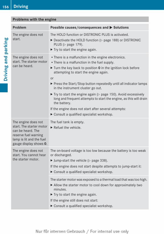
Problems with the engine
Problem Possible causes/consequences and M Solutions
The engine does notstart.
The HOLD function or DISTRONIC PLUS is activated.X Deactivate the HOLD function (Y page 188) or DISTRONIC
PLUS (Y page 179).X Try to start the engine again.
The engine does notstart. The starter motorcan be heard.
RThere is a malfunction in the engine electronics.RThere is a malfunction in the fuel supply.X Turn the key back to position 0 in the ignition lock before
attempting to start the engine again.orX Press the Start/Stop button repeatedly until all indicator lamps
in the instrument cluster go out.X Try to start the engine again (Y page 150). Avoid excessively
long and frequent attempts to start the engine, as this will drainthe battery.
If the engine does not start after several attempts:X Consult a qualified specialist workshop.
The engine does notstart. The starter motorcan be heard. Thereserve fuel warninglamp is lit and the fuelgauge display shows 0.
The fuel tank is empty.X Refuel the vehicle.
The engine does notstart. You cannot hearthe starter motor.
The on-board voltage is too low because the battery is too weakor discharged.X Jump-start the vehicle (Y page 338).If the engine does not start despite attempts to jump-start it:X Consult a qualified specialist workshop.
The starter motor was exposed to a thermal load that was too high.X Allow the starter motor to cool down for approximately two
minutes.X Try to start the engine again.If the engine still does not start:X Consult a qualified specialist workshop.
156 DrivingDr
ivin
g an
d pa
rkin
g
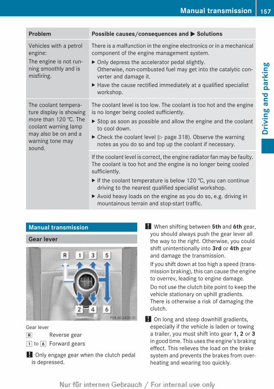
Problem Possible causes/consequences and M Solutions
Vehicles with a petrolengine:The engine is not run-ning smoothly and ismisfiring.
There is a malfunction in the engine electronics or in a mechanicalcomponent of the engine management system.X Only depress the accelerator pedal slightly.
Otherwise, non-combusted fuel may get into the catalytic con-verter and damage it.
X Have the cause rectified immediately at a qualified specialistworkshop.
The coolant tempera-ture display is showingmore than 120 †. Thecoolant warning lampmay also be on and awarning tone maysound.
The coolant level is too low. The coolant is too hot and the engineis no longer being cooled sufficiently.X Stop as soon as possible and allow the engine and the coolant
to cool down.X Check the coolant level (Y page 318). Observe the warning
notes as you do so and top up the coolant if necessary.
If the coolant level is correct, the engine radiator fan may be faulty.The coolant is too hot and the engine is no longer being cooledsufficiently.X If the coolant temperature is below 120 †, you can continue
driving to the nearest qualified specialist workshop.X Avoid heavy loads on the engine as you do so, e.g. driving in
mountainous terrain and stop-start traffic.
Manual transmission
Gear lever
Gear leverk Reverse gear1 to 6 Forward gears
! Only engage gear when the clutch pedalis depressed.
! When shifting between 5th and 6th gear,you should always push the gear lever allthe way to the right. Otherwise, you couldshift unintentionally into 3rd or 4th gearand damage the transmission.If you shift down at too high a speed (trans-mission braking), this can cause the engineto overrev, leading to engine damage.Do not use the clutch bite point to keep thevehicle stationary on uphill gradients.There is otherwise a risk of damaging theclutch.
! On long and steep downhill gradients,especially if the vehicle is laden or towinga trailer, you must shift into gear 1, 2 or 3in good time. This uses the engine's brakingeffect. This relieves the load on the brakesystem and prevents the brakes from over-heating and wearing too quickly.
Manual transmission 157
Driv
ing
and
park
ing
Z
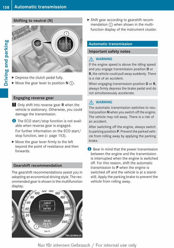
Shifting to neutral (N)
X Depress the clutch pedal fully.X Move the gear lever to position N :.
Engaging reverse gear! Only shift into reverse gear R when the
vehicle is stationary. Otherwise, you coulddamage the transmission.
i The ECO start/stop function is not avail-able when reverse gear is engaged.For further information on the ECO start/stop function, see (Y page 153).
X Move the gear lever firmly to the leftbeyond the point of resistance and thenforwards.
Gearshift recommendationThe gearshift recommendations assist you inadopting an economical driving style. The rec-ommended gear is shown in the multifunctiondisplay.
X Shift gear according to gearshift recom-mendation : when shown in the multi-function display of the instrument cluster.
Automatic transmission
Important safety notes
G WARNINGIf the engine speed is above the idling speedand you engage transmission position D orR, the vehicle could pull away suddenly. Thereis a risk of an accident.When engaging transmission position D or R,always firmly depress the brake pedal and donot simultaneously accelerate.
G WARNINGThe automatic transmission switches to neu-tral position N when you switch off the engine.The vehicle may roll away. There is a risk ofan accident.After switching off the engine, always switchto parking position P. Prevent the parked vehi-cle from rolling away by applying the parkingbrake.
i Bear in mind that the power transmissionbetween the engine and the transmissionis interrupted when the engine is switchedoff. For this reason, shift the automatictransmission to P when the engine isswitched off and the vehicle is at a stand-still. Apply the parking brake to prevent thevehicle from rolling away.
158 Automatic transmissionDr
ivin
g an
d pa
rkin
g
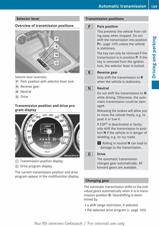
Selector lever
Overview of transmission positions
Selector lever (example)j Park position with selector lever lockk Reverse geari Neutralh Drive
Transmission position and drive pro-gram display
: Transmission position display; Drive program display
The current transmission position and driveprogram appear in the multifunction display.
Transmission positions
B Park positionThis prevents the vehicle from roll-ing away when stopped. Do notshift the transmission into positionP(Y page 169) unless the vehicleis stationary.The key can only be removed if thetransmission is in position P. If thekey is removed from the ignitionlock, the selector lever is locked.
C Reverse gearOnly shift the transmission to Rwhen the vehicle is stationary.
A NeutralDo not shift the transmission to Nwhile driving. Otherwise, the auto-matic transmission could be dam-aged.Releasing the brakes will allow youto move the vehicle freely, e.g. topush it or tow it.If ESP® is deactivated or faulty:only shift the transmission to posi-tion N if the vehicle is in danger ofskidding, e.g. on icy roads.
! Rolling in neutral N can lead todamage to the transmission.
7 DriveThe automatic transmissionchanges gear automatically. Allforward gears are available.
Changing gearThe automatic transmission shifts to the indi-vidual gears automatically when it is in trans-mission position D. Gearshifting is deter-mined by:Ra shift range restriction, if selectedRthe selected drive program (Y page 160)
Automatic transmission 159
Driv
ing
and
park
ing
Z
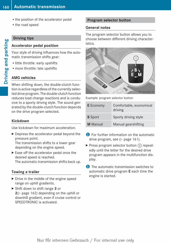
Rthe position of the accelerator pedalRthe road speed
Driving tips
Accelerator pedal positionYour style of driving influences how the auto-matic transmission shifts gear:Rlittle throttle: early upshiftsRmore throttle: late upshifts
AMG vehiclesWhen shifting down, the double-clutch func-tion is active regardless of the currently selec-ted drive program. The double-clutch functionreduces load change reactions and is condu-cive to a sporty driving style. The sound gen-erated by the double-clutch function dependson the drive program selected.
KickdownUse kickdown for maximum acceleration.X Depress the accelerator pedal beyond the
pressure point.The transmission shifts to a lower geardepending on the engine speed.
X Ease off the accelerator pedal once thedesired speed is reached.The automatic transmission shifts back up.
Towing a trailerX Drive in the middle of the engine speed
range on uphill gradients.X Shift down to shift range 3 or
2(Y page 162) depending on the uphill ordownhill gradient, even if cruise control orSPEEDTRONIC is activated.
Program selector button
General notesThe program selector button allows you tochoose between different driving character-istics.
Example: program selector button
E Economy Comfortable, economicaldriving
S Sport Sporty driving style
M Manual Manual gearshifting
i For further information on the automaticdrive program, see (Y page 161).
X Press program selector button : repeat-edly until the letter for the desired driveprogram appears in the multifunction dis-play.
i The automatic transmission switches toautomatic drive program E each time theengine is started.
160 Automatic transmissionDr
ivin
g an
d pa
rkin
g
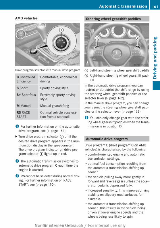
AMG vehicles
Drive program selector with manual drive program
C ControlledEfficiency
Comfortable, economicaldriving
S Sport Sporty driving style
S+ SportPlus Extremely sporty drivingstyle
M Manual Manual gearshifting
RS RACESTART
Optimal vehicle accelera-tion from a standstill
i For further information on the automaticdrive program, see (Y page 161).
X Turn drive program selector : until thedesired drive program appears in the mul-tifunction display in the speedometer.The drive program indicator on drive pro-gram selector : lights up in red.
i The automatic transmission switches toautomatic drive program C each time theengine is started.
i RS cannot be selected during normal driv-ing. For further information on RACESTART; see (Y page 190).
Steering wheel gearshift paddles
: Left-hand steering wheel gearshift paddle; Right-hand steering wheel gearshift pad-
dleIn the automatic drive program, you canrestrict or derestrict the shift range by usingthe steering wheel gearshift paddles or theselector lever (Y page 162).In the manual drive program, you can changegear using the steering wheel gearshift pad-dles or the selector lever (Y page 163).
i You can only change gear with the steer-ing wheel gearshift paddles when the trans-mission is in position D.
Automatic drive programDrive program E (drive program C on AMGvehicles) is characterised by the following:Rcomfort-oriented engine and automatic
transmission settings.Roptimal fuel consumption resulting from
the automatic transmission shifting upsooner.Rthe vehicle pulling away more gently in
forward and reverse gears unless the accel-erator pedal is depressed fully.Rincreased sensitivity. This improves driving
stability on slippery road surfaces, forexample.Rthe automatic transmission shifting up
sooner. This results in the vehicle beingdriven at lower engine speeds and thewheels being less likely to spin.
Automatic transmission 161
Driv
ing
and
park
ing
Z
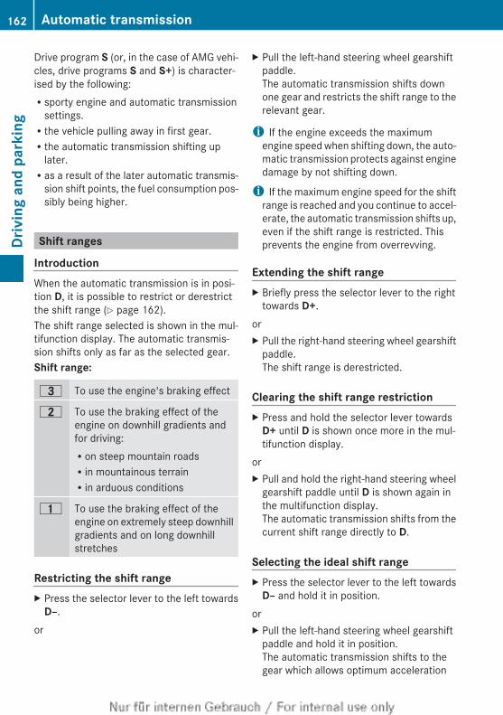
Drive program S (or, in the case of AMG vehi-cles, drive programs S and S+) is character-ised by the following:Rsporty engine and automatic transmission
settings.Rthe vehicle pulling away in first gear.Rthe automatic transmission shifting up
later.Ras a result of the later automatic transmis-
sion shift points, the fuel consumption pos-sibly being higher.
Shift ranges
IntroductionWhen the automatic transmission is in posi-tion D, it is possible to restrict or derestrictthe shift range (Y page 162).The shift range selected is shown in the mul-tifunction display. The automatic transmis-sion shifts only as far as the selected gear.Shift range:
= To use the engine's braking effect
5 To use the braking effect of theengine on downhill gradients andfor driving:Ron steep mountain roadsRin mountainous terrainRin arduous conditions
4 To use the braking effect of theengine on extremely steep downhillgradients and on long downhillstretches
Restricting the shift rangeX Press the selector lever to the left towards
D–.or
X Pull the left-hand steering wheel gearshiftpaddle.The automatic transmission shifts downone gear and restricts the shift range to therelevant gear.
i If the engine exceeds the maximumengine speed when shifting down, the auto-matic transmission protects against enginedamage by not shifting down.
i If the maximum engine speed for the shiftrange is reached and you continue to accel-erate, the automatic transmission shifts up,even if the shift range is restricted. Thisprevents the engine from overrevving.
Extending the shift rangeX Briefly press the selector lever to the right
towards D+.orX Pull the right-hand steering wheel gearshift
paddle.The shift range is derestricted.
Clearing the shift range restrictionX Press and hold the selector lever towards
D+ until D is shown once more in the mul-tifunction display.
orX Pull and hold the right-hand steering wheel
gearshift paddle until D is shown again inthe multifunction display.The automatic transmission shifts from thecurrent shift range directly to D.
Selecting the ideal shift rangeX Press the selector lever to the left towards
D– and hold it in position.orX Pull the left-hand steering wheel gearshift
paddle and hold it in position.The automatic transmission shifts to thegear which allows optimum acceleration
162 Automatic transmissionDr
ivin
g an
d pa
rkin
g
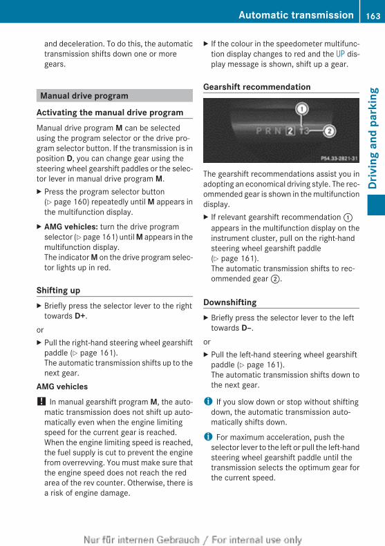
and deceleration. To do this, the automatictransmission shifts down one or moregears.
Manual drive program
Activating the manual drive programManual drive program M can be selectedusing the program selector or the drive pro-gram selector button. If the transmission is inposition D, you can change gear using thesteering wheel gearshift paddles or the selec-tor lever in manual drive program M.X Press the program selector button
(Y page 160) repeatedly until M appears inthe multifunction display.
X AMG vehicles: turn the drive programselector (Y page 161) until M appears in themultifunction display.The indicator M on the drive program selec-tor lights up in red.
Shifting upX Briefly press the selector lever to the right
towards D+.orX Pull the right-hand steering wheel gearshift
paddle (Y page 161).The automatic transmission shifts up to thenext gear.
AMG vehicles! In manual gearshift program M, the auto-
matic transmission does not shift up auto-matically even when the engine limitingspeed for the current gear is reached.When the engine limiting speed is reached,the fuel supply is cut to prevent the enginefrom overrevving. You must make sure thatthe engine speed does not reach the redarea of the rev counter. Otherwise, there isa risk of engine damage.
X If the colour in the speedometer multifunc-tion display changes to red and the UP dis-play message is shown, shift up a gear.
Gearshift recommendation
The gearshift recommendations assist you inadopting an economical driving style. The rec-ommended gear is shown in the multifunctiondisplay.X If relevant gearshift recommendation :
appears in the multifunction display on theinstrument cluster, pull on the right-handsteering wheel gearshift paddle(Y page 161).The automatic transmission shifts to rec-ommended gear ;.
DownshiftingX Briefly press the selector lever to the left
towards D–.orX Pull the left-hand steering wheel gearshift
paddle (Y page 161).The automatic transmission shifts down tothe next gear.
i If you slow down or stop without shiftingdown, the automatic transmission auto-matically shifts down.
i For maximum acceleration, push theselector lever to the left or pull the left-handsteering wheel gearshift paddle until thetransmission selects the optimum gear forthe current speed.
Automatic transmission 163
Driv
ing
and
park
ing
Z
Kickdowni AMG vehicles: it is not possible to use
kickdown in manual drive program M.You can also use kickdown for maximumacceleration in manual drive program M.X Depress the accelerator pedal beyond the
pressure point.The transmission shifts to a lower geardepending on the engine speed.
Deactivating the manual drive programX Vehicles without the dynamic handling
package with sports mode: press theprogram selector button (Y page 160)repeatedly until E or S appears in the mul-tifunction display.
X Vehicles with the dynamic handling package with sports mode: press theprogram selector button (Y page 160). Mis no longer shown in the multifunction dis-play.
X AMG vehicles: turn the drive programselector (Y page 161) until C, S or S+appears in the multifunction display.
164 Automatic transmissionDr
ivin
g an
d pa
rkin
g
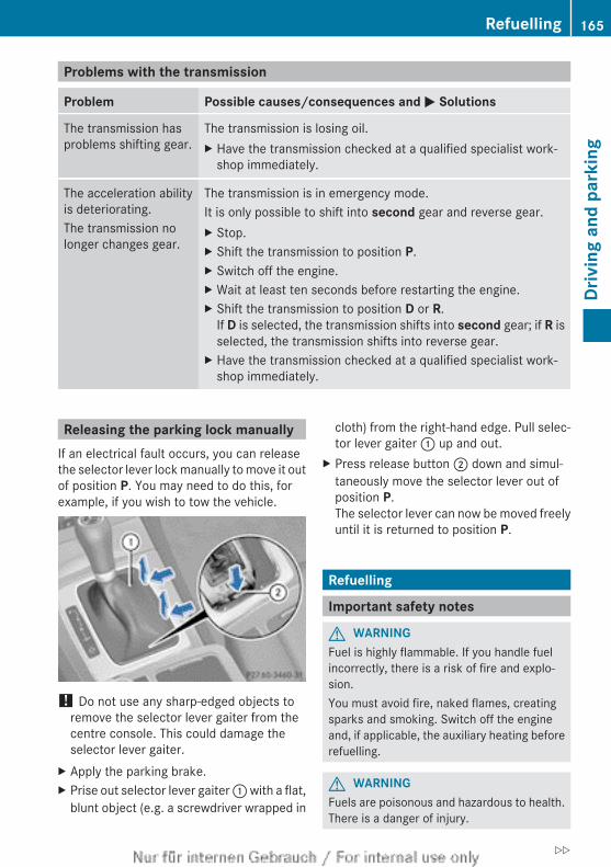
Problems with the transmission
Problem Possible causes/consequences and M Solutions
The transmission hasproblems shifting gear.
The transmission is losing oil.X Have the transmission checked at a qualified specialist work-
shop immediately.
The acceleration abilityis deteriorating.The transmission nolonger changes gear.
The transmission is in emergency mode.It is only possible to shift into second gear and reverse gear.X Stop.X Shift the transmission to position P.X Switch off the engine.X Wait at least ten seconds before restarting the engine.X Shift the transmission to position D or R.
If D is selected, the transmission shifts into second gear; if R isselected, the transmission shifts into reverse gear.
X Have the transmission checked at a qualified specialist work-shop immediately.
Releasing the parking lock manuallyIf an electrical fault occurs, you can releasethe selector lever lock manually to move it outof position P. You may need to do this, forexample, if you wish to tow the vehicle.
! Do not use any sharp-edged objects toremove the selector lever gaiter from thecentre console. This could damage theselector lever gaiter.
X Apply the parking brake.X Prise out selector lever gaiter : with a flat,
blunt object (e.g. a screwdriver wrapped in
cloth) from the right-hand edge. Pull selec-tor lever gaiter : up and out.
X Press release button ; down and simul-taneously move the selector lever out ofposition P.The selector lever can now be moved freelyuntil it is returned to position P.
Refuelling
Important safety notes
G WARNINGFuel is highly flammable. If you handle fuelincorrectly, there is a risk of fire and explo-sion.You must avoid fire, naked flames, creatingsparks and smoking. Switch off the engineand, if applicable, the auxiliary heating beforerefuelling.
G WARNINGFuels are poisonous and hazardous to health.There is a danger of injury.
Refuelling 165
Driv
ing
and
park
ing
Z
Do not swallow fuel or let it come into contactwith skin, eyes or clothing. Do not inhale fuelvapours. Keep fuels out of the reach of chil-dren.If you or others come into contact with fuel,observe the following:RWash the fuel off any affected areas of skin
with water and soap immediately.RIf you get fuel in your eyes, rinse them thor-
oughly with clean water immediately. Seekimmediate medical attention.RIf fuel is swallowed, seek immediate medi-
cal attention. Do not induce vomiting.RChange any clothing that has come into
contact with fuel immediately.
G WARNINGElectrostatic charge can cause sparks andthereby ignite fuel vapours. There is a risk offire and explosion.Always touch the vehicle body before openingthe fuel filler flap or touching the fuel pumpnozzle. This discharges any electrostaticcharge that may have built up.
G WARNINGVehicles with a diesel engine:If you mix diesel fuel with petrol, the flashpoint of this fuel mixture is lower than that ofpure diesel fuel. When the engine is running,components in the exhaust system may over-heat unnoticed. There is a risk of fire.Never refuel with petrol. Never add petrol todiesel fuel.
! Do not use petrol to refuel vehicles with adiesel engine. Do not use diesel to refuelvehicles with a petrol engine. Do not switchon the ignition if you accidentally refuelwith the wrong fuel. Otherwise, the fuel willenter the fuel system. Even small amountsof the wrong fuel could result in damage tothe fuel system and the engine. The repaircosts are high. Notify a qualified specialistworkshop and have the fuel tank and fuellines drained completely.
! Overfilling the fuel tank could damage thefuel system.
! Take care not to spill any fuel on paintedsurfaces. You could otherwise damage thepaintwork.
! Use a filter when adding fuel from a fuelcan. The fuel lines and/or the diesel injec-tion system could otherwise be blocked byparticles from the fuel can.
Do not get into the vehicle again during therefuelling process. Otherwise, electrostaticcharge could build up again.If you overfill the fuel tank, some fuel mayspray out when you remove the fuel pumpnozzle.For further information on fuel and fuel quality(Y page 372).
Refuelling
Opening/closing the fuel filler flap
: To open the fuel filler flap; To insert the fuel filler cap= Tyre pressure table? Fuel type to be refuelled
The fuel filler flap is unlocked or locked auto-matically when you open or close the vehiclewith the key or using KEYLESS-GO.The position of the fuel filler cap 8 is dis-played in the instrument cluster. The arrownext to the filling pump indicates the side ofthe vehicle.
166 RefuellingDr
ivin
g an
d pa
rkin
g
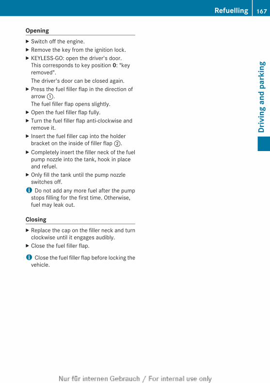
OpeningX Switch off the engine.X Remove the key from the ignition lock.X KEYLESS-GO: open the driver's door.
This corresponds to key position 0: "keyremoved".The driver's door can be closed again.
X Press the fuel filler flap in the direction ofarrow :.The fuel filler flap opens slightly.
X Open the fuel filler flap fully.X Turn the fuel filler flap anti-clockwise and
remove it.X Insert the fuel filler cap into the holder
bracket on the inside of filler flap ;.X Completely insert the filler neck of the fuel
pump nozzle into the tank, hook in placeand refuel.
X Only fill the tank until the pump nozzleswitches off.
i Do not add any more fuel after the pumpstops filling for the first time. Otherwise,fuel may leak out.
ClosingX Replace the cap on the filler neck and turn
clockwise until it engages audibly.X Close the fuel filler flap.
i Close the fuel filler flap before locking thevehicle.
Refuelling 167
Driv
ing
and
park
ing
Z
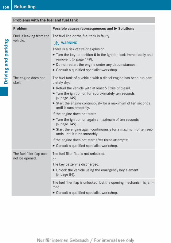
Problems with the fuel and fuel tank
Problem Possible causes/consequences and M Solutions
Fuel is leaking from thevehicle.
The fuel line or the fuel tank is faulty.
G WARNINGThere is a risk of fire or explosion.X Turn the key to position 0 in the ignition lock immediately and
remove it (Y page 149).X Do not restart the engine under any circumstances.X Consult a qualified specialist workshop.
The engine does notstart.
The fuel tank of a vehicle with a diesel engine has been run com-pletely dry.X Refuel the vehicle with at least 5 litres of diesel.X Turn the ignition on for approximately ten seconds
(Y page 149).X Start the engine continuously for a maximum of ten seconds
until it runs smoothly.If the engine does not start:X Turn the ignition on again a maximum of ten seconds
(Y page 149).X Start the engine again continuously for a maximum of ten sec-
onds until it runs smoothly.If the engine does not start after three attempts:X Consult a qualified specialist workshop.
The fuel filler flap can-not be opened.
The fuel filler flap is not unlocked.orThe key battery is discharged.X Unlock the vehicle using the emergency key element
(Y page 84).
The fuel filler flap is unlocked, but the opening mechanism is jam-med.X Consult a qualified specialist workshop.
168 RefuellingDr
ivin
g an
d pa
rkin
g
Parking
Important safety notes
G WARNINGFlammable material such as leaves, grass ortwigs may ignite if they come into contact withhot parts of the exhaust system or exhaustgas flow. There is a risk of fire.Park the vehicle so that no flammable mate-rial can come into contact with hot vehiclecomponents. In particular, do not park on drygrassland or harvested grain fields.
G WARNINGIf you switch off the ignition while driving,safety-relevant functions are only availablewith limitations, or not at all. This could affect,for example, the power steering and the brakeboosting effect. You will require considerablymore effort to steer and brake. There is a riskof an accident.Do not switch off the ignition while driving.
G WARNINGIf you leave children unattended in the vehi-cle, they may be able to set the vehicle inmotion if, for example, they:Rrelease the parking brakeRshift the automatic transmission out of park
position P or shift manual transmission intoneutralRstart the engineIn addition, they may operate vehicle equip-ment and become trapped. There is a risk ofan accident and injury.When leaving the vehicle, always take the keywith you and lock the vehicle. Never leavechildren unattended in the vehicle.
! Always secure the vehicle correctlyagainst rolling away. Otherwise, the vehicleor its drivetrain could be damaged.
To ensure that the vehicle is secured againstrolling away unintentionally:Rthe parking brake must be applied.Ron vehicles with manual transmission,
engage first gear or reverse gear.Ron vehicles with automatic transmission,
the transmission must be in position P andthe key must be removed from the ignitionlock.Ron uphill or downhill gradients, the front
wheels must be turned towards the kerb.
Switching off the engine
Important safety notes
G WARNINGThe automatic transmission switches to neu-tral position N when you switch off the engine.The vehicle may roll away. There is a risk ofan accident.After switching off the engine, always switchto parking position P. Prevent the parked vehi-cle from rolling away by applying the parkingbrake.
Vehicles with manual transmissionX Shift to either first gear or reverse gear R.X Turn the key to position 0 in the ignition
lock and remove it.The immobiliser is activated.
X Firmly depress the parking brake.
Vehicles with automatic transmissionX Firmly depress the parking brake.X Shift the transmission to position P.
Using the keyX Turn the key to position 0 in the ignition
lock and remove it.The immobiliser is activated.
i The key can only be removed if the trans-mission is in position P.
Parking 169
Driv
ing
and
park
ing
Z
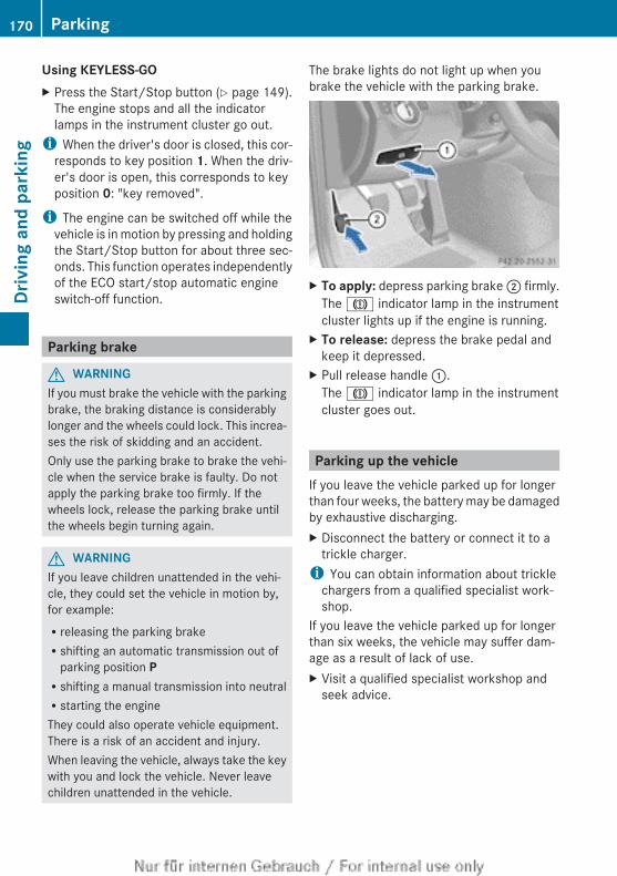
Using KEYLESS-GOX Press the Start/Stop button (Y page 149).
The engine stops and all the indicatorlamps in the instrument cluster go out.
i When the driver's door is closed, this cor-responds to key position 1. When the driv-er's door is open, this corresponds to keyposition 0: "key removed".
i The engine can be switched off while thevehicle is in motion by pressing and holdingthe Start/Stop button for about three sec-onds. This function operates independentlyof the ECO start/stop automatic engineswitch-off function.
Parking brake
G WARNINGIf you must brake the vehicle with the parkingbrake, the braking distance is considerablylonger and the wheels could lock. This increa-ses the risk of skidding and an accident.Only use the parking brake to brake the vehi-cle when the service brake is faulty. Do notapply the parking brake too firmly. If thewheels lock, release the parking brake untilthe wheels begin turning again.
G WARNINGIf you leave children unattended in the vehi-cle, they could set the vehicle in motion by,for example:Rreleasing the parking brakeRshifting an automatic transmission out of
parking position PRshifting a manual transmission into neutralRstarting the engineThey could also operate vehicle equipment.There is a risk of an accident and injury.When leaving the vehicle, always take the keywith you and lock the vehicle. Never leavechildren unattended in the vehicle.
The brake lights do not light up when youbrake the vehicle with the parking brake.
X To apply: depress parking brake ; firmly.The J indicator lamp in the instrumentcluster lights up if the engine is running.
X To release: depress the brake pedal andkeep it depressed.
X Pull release handle :.The J indicator lamp in the instrumentcluster goes out.
Parking up the vehicleIf you leave the vehicle parked up for longerthan four weeks, the battery may be damagedby exhaustive discharging.X Disconnect the battery or connect it to a
trickle charger.i You can obtain information about trickle
chargers from a qualified specialist work-shop.
If you leave the vehicle parked up for longerthan six weeks, the vehicle may suffer dam-age as a result of lack of use.X Visit a qualified specialist workshop and
seek advice.
170 ParkingDr
ivin
g an
d pa
rkin
g
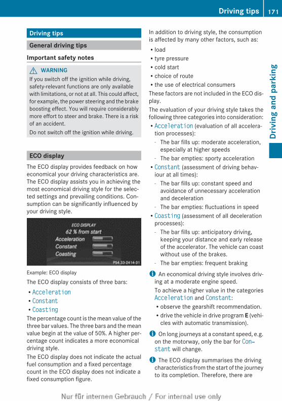
Driving tips
General driving tips
Important safety notes
G WARNINGIf you switch off the ignition while driving,safety-relevant functions are only availablewith limitations, or not at all. This could affect,for example, the power steering and the brakeboosting effect. You will require considerablymore effort to steer and brake. There is a riskof an accident.Do not switch off the ignition while driving.
ECO displayThe ECO display provides feedback on howeconomical your driving characteristics are.The ECO display assists you in achieving themost economical driving style for the selec-ted settings and prevailing conditions. Con-sumption can be significantly influenced byyour driving style.
Example: ECO display
The ECO display consists of three bars:RAccelerationRConstantRCoastingThe percentage count is the mean value of thethree bar values. The three bars and the meanvalue begin at the value of 50%. A higher per-centage count indicates a more economicaldriving style.The ECO display does not indicate the actualfuel consumption and a fixed percentagecount in the ECO display does not indicate afixed consumption figure.
In addition to driving style, the consumptionis affected by many other factors, such as:RloadRtyre pressureRcold startRchoice of routeRthe use of electrical consumersThese factors are not included in the ECO dis-play.The evaluation of your driving style takes thefollowing three categories into consideration:RAcceleration (evaluation of all accelera-
tion processes):- The bar fills up: moderate acceleration,
especially at higher speeds- The bar empties: sporty accelerationRConstant (assessment of driving behav-
iour at all times):- The bar fills up: constant speed and
avoidance of unnecessary accelerationand deceleration
- The bar empties: fluctuations in speedRCoasting (assessment of all deceleration
processes):- The bar fills up: anticipatory driving,
keeping your distance and early releaseof the accelerator. The vehicle can coastwithout use of the brakes.
- The bar empties: frequent braking
i An economical driving style involves driv-ing at a moderate engine speed.To achieve a higher value in the categoriesAcceleration and Constant:Robserve the gearshift recommendation.Rdrive the vehicle in drive program E (vehi-
cles with automatic transmission).
i On long journeys at a constant speed, e.g.on the motorway, only the bar for Con‐stant will change.
i The ECO display summarises the drivingcharacteristics from the start of the journeyto its completion. Therefore, there are
Driving tips 171
Driv
ing
and
park
ing
Z
dynamic changes in the bars at the start ofa journey. During a prolonged driving time,these changes are smaller. For moredynamic changes, perform a manual reset.
For further information on the ECO display,see (Y page 223).
Braking
Important safety notes
G WARNINGIf you shift down on a slippery road surface inan attempt to increase the engine's brakingeffect, the drive wheels could lose their grip.This increases the risk of skidding and havingan accident.Do not shift down for additional engine brak-ing on a slippery road surface.
Downhill gradientsOn long and steep downhill gradients, youmust:Rshift to a lower gear in good time, orRon vehicles with automatic transmission,
select shift range 1, 2 or 3.Take particular note of this when driving aladen vehicle and when towing a trailer.
i This also applies if you have activatedcruise control, SPEEDTRONIC or DIS-TRONIC PLUS.
This will use the braking effect of the engine,so less braking will be required to maintainvehicle speed. This relieves the load on thebrake system and prevents the brakes fromoverheating and wearing too quickly.
Heavy and light loads
G WARNINGThe braking system can overheat if you leaveyour foot on the brake pedal while driving.This increases the braking distance and could
even cause the braking system to fail. Thereis a risk of an accident.Never use the brake pedal as a footrest. Donot simultaneously depress both the brakepedal and the accelerator pedal while driving.
! Depressing the brake pedal constantlyresults in excessive and premature wear tothe brake pads.
If heavy demands are made on the brakes, donot park the vehicle immediately. Drive on fora short while. This allows the airflow to coolthe brakes more quickly.If the brakes have been used only moderately,you should occasionally test their effective-ness. To do this, brake more firmly from ahigher speed. This improves the grip of thebrakes.
Wet road surfacesIf you have driven for a long time in heavy rainwithout braking, there may be a delayed reac-tion from the brakes when braking for the firsttime. This may also occur after the vehicle hasbeen washed.You have to depress the brake pedal morefirmly. Maintain a greater distance from thevehicle in front.After driving on a wet road or having the vehi-cle washed, brake firmly while paying atten-tion to the traffic conditions. This will warmup the brake discs, thereby drying them morequickly and protecting them against corro-sion.
Limited braking performance on salt-treated roadsIf you drive on salt-treated roads, a layer ofsalt may form on the brake discs and pads.This can increase the braking distance con-siderably.
172 Driving tipsDr
ivin
g an
d pa
rkin
g
RBrake occasionally to remove any possiblesalt residue. Ensure that you do not endan-ger other road users when doing so.RCarefully depress the brake pedal at the
end of the journey and when starting thenext journey.RMaintain a much greater distance to the
vehicle in front.
New brake pads/liningsNew brake pads/brake pads and discs thathave been replaced only achieve optimumbraking effect after several hundred kilome-tres of driving. Compensate for the reducedbraking effect by applying greater force to thebrake pedal.For safety reasons, Mercedes-Benz recom-mends that you only have brake pads/liningsfitted to your vehicle which have beenapproved for Mercedes-Benz vehicles orwhich correspond to an equivalent qualitystandard. Brake pads/linings which have notbeen approved for Mercedes-Benz vehicles orwhich are not of an equivalent quality couldaffect your vehicle's operating safety.
High-performance brake system forAMG vehiclesThe high-performance brake system isdesigned for high loads. This may lead tonoise when braking. This is dependent on:RspeedRbraking forceRenvironmental conditions, such as temper-
ature and humidityThe wear and tear on individual brake systemcomponents, e.g. brake pads or discs,depends on:Rthe individual driving styleRthe operating conditionsFor this reason, it is impossible to state amileage (service life) that will be valid underall circumstances. An aggressive driving stylewill lead to high wear. You can obtain further
information about this from your Mercedes-Benz Service Centre.New brake pads/linings and discs that havebeen replaced only achieve optimum brakingeffect after several hundred kilometres ofdriving. Compensate for the reduced brakingeffect by applying greater force to the brakepedal. Always be aware of this and adapt yourdriving and braking accordingly during therunning-in period.Excessive heavy braking results in corre-spondingly high brake wear. Observe thebrake wear warning lamp in the instrumentcluster and note any brake status messagesin the multifunction display. If you regularlydrive at high speeds, it is particularly impor-tant to have the brake system checked andmaintained regularly.
Driving on wet roads
AquaplaningIf water has accumulated to a certain depthon the road surface, there is a danger of aqua-planing occurring, even if:Ryou are driving at low speedsRthe tyres have adequate tread depthFor this reason, do not drive in tyre ruts andbrake carefully.
Driving on flooded roadsIf you have to drive on stretches of road onwhich water has collected, please bear inmind that:Rthe maximum permissible fording depth in
still water is 25 cmRyou should drive no faster than walking
pace
! Bear in mind that vehicles travelling infront or in the opposite direction createwaves. This may cause the maximum per-missible water depth to be exceeded.These notes must be observed under allcircumstances. You could otherwise dam-
Driving tips 173
Driv
ing
and
park
ing
Z
age the engine, the electronics or the trans-mission.
Winter driving
Important safety notes
G WARNINGIf you shift down on a slippery road surface inan attempt to increase the engine's brakingeffect, the drive wheels could lose their grip.This increases the risk of skidding and havingan accident.Do not shift down for additional engine brak-ing on a slippery road surface.
G DANGERIf the exhaust pipe is blocked or adequateventilation is not possible, poisonous gasessuch as carbon monoxide (CO) may enter thevehicle. This is the case, e.g. if the vehiclebecomes trapped in snow. There is a risk offatal injury.If you leave the engine or the auxiliary heatingrunning, make sure the exhaust pipe and areaaround the vehicle are clear of snow. Toensure an adequate supply of fresh air, opena window on the side of the vehicle that is notfacing into the wind.
Have your vehicle winterproofed at a qualifiedspecialist workshop at the onset of winter.Observe the notes in the "Winter operation"section (Y page 348).
Driving with summer tyresObserve the notes in the "Winter operation"section (Y page 348).
Slippery road surfaces
G WARNINGIf you shift down on a slippery road surface inan attempt to increase the engine's brakingeffect, the drive wheels could lose their grip.
This increases the risk of skidding and havingan accident.Do not shift down for additional engine brak-ing on a slippery road surface.
You should drive particularly carefully on slip-pery road surfaces. Avoid sudden accelera-tion, steering and braking manoeuvres.If the vehicle threatens to skid or cannot bestopped when moving at low speed:X Vehicles with manual transmission:
shift to neutral.X Vehicles with automatic transmission:
shift the transmission to position N.X Try to bring the vehicle under control by
using corrective steering.
i For more information on driving withsnow chains, see (Y page 349).
The outside temperature indicator is notdesigned to serve as an ice-warning deviceand is therefore unsuitable for that purpose.Changes in the outside temperature are dis-played after a short delay.Indicated temperatures just above the freez-ing point do not guarantee that the road sur-face is free of ice. The road may still be icy,especially in wooded areas or on bridges. Thevehicle could skid if you fail to adapt yourdriving style. Always adapt your driving styleand drive at a speed to suit the prevailingweather conditions.You should pay special attention to road con-ditions when temperatures are around thefreezing point.
Driving systems
Cruise control
Important safety notesCruise control maintains a constant roadspeed for you. It brakes automatically in orderto avoid exceeding the set speed. You mustselect a low gear in good time on long and
174 Driving systemsDr
ivin
g an
d pa
rkin
g
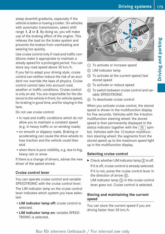
steep downhill gradients, especially if thevehicle is laden or towing a trailer. On vehicleswith automatic transmission, select shiftrange 1, 2 or 3. By doing so, you will makeuse of the braking effect of the engine. Thisrelieves the load on the brake system andprevents the brakes from overheating andwearing too quickly.Use cruise control only if road and traffic con-ditions make it appropriate to maintain asteady speed for a prolonged period. You canstore any road speed above 30 km/h.If you fail to adapt your driving style, cruisecontrol can neither reduce the risk of an acci-dent nor override the laws of physics. Cruisecontrol cannot take into account road,weather or traffic conditions. Cruise controlis only an aid. You are responsible for the dis-tance to the vehicle in front, for vehicle speed,for braking in good time, and for staying in thelane.Do not use cruise control:Rin road and traffic conditions which do not
allow you to maintain a constant speed(e.g. in heavy traffic or on winding roads)Ron smooth or slippery roads. Braking or
accelerating can cause the drive wheels tolose traction and the vehicle could thenskidRwhen there is poor visibility, e.g. due to fog,
heavy rain or snowIf there is a change of drivers, advise the newdriver of the speed stored.
Cruise control leverYou can operate cruise control and variableSPEEDTRONIC with the cruise control lever.The LIM indicator lamp on the cruise controllever indicates which system you have selec-ted:RLIM indicator lamp off: cruise control is
selected.RLIM indicator lamp on: variable SPEED-
TRONIC is selected.
: To activate or increase speed; LIM indicator lamp= To activate at the current speed/last
stored speed? To activate or reduce speedA To switch between cruise control and var-
iable SPEEDTRONICB To deactivate cruise control
When you activate cruise control, the storedspeed is shown in the multifunction displayfor five seconds. Vehicles with the 4-buttonmultifunction steering wheel: the storedspeed is then permanently displayed in thestatus indicator together with the ¯ sym-bol. Vehicles with the 12-button multifunc-tion steering wheel: the segments from thestored speed up to the maximum speed lightup in the multifunction display.
Selecting cruise controlX Check whether LIM indicator lamp ; is off.
If it is off, cruise control is already selected.If it is not, press the cruise control lever inthe direction of arrow A.LIM indicator lamp ; in the cruise controllever goes out. Cruise control is selected.
Storing and maintaining the currentspeedYou can store the current speed if you aredriving faster than 30 km/h.
Driving systems 175
Driv
ing
and
park
ing
Z
X Accelerate the vehicle to the desiredspeed.
X Briefly press the cruise control leverup : or down ?.
X Remove your foot from the acceleratorpedal.Cruise control is activated. The vehicleautomatically maintains the speed.
i Cruise control may be unable to maintainthe stored speed on uphill gradients. Thestored speed is resumed when the gradientevens out. Cruise control maintains thestored speed on downhill gradients byautomatically braking the vehicle.
i Vehicles with manual transmission:Ralways drive at adequate, but not exces-
sive, engine speeds.Rchange gear in good time.Rif possible, do not change down several
gears at a time.
Storing the current speed and calling upthe last stored speed
G WARNINGIf you call up a stored speed and this is dif-ferent from the current speed, the vehicleaccelerates or brakes. If you do not knowwhat the stored speed is, the vehicle mayaccelerate or brake unexpectedly. There is arisk of an accident.Take the traffic conditions into accountbefore calling up the stored speed. If you donot know what the stored speed is, store thedesired speed again.
X Briefly pull the cruise control lever towardsyou =.
X Remove your foot from the acceleratorpedal.The first time cruise control is activated, itstores the current speed or regulates thespeed of the vehicle to the previouslystored speed.
Setting a speedKeep in mind that it may take a brief momentuntil the vehicle has accelerated or braked tothe set speed.X Press the cruise control lever up : for a
higher speed or down ? for a lower speed.X Keep the cruise control lever pressed until
the desired speed is reached.X Release the cruise control lever.
The new speed is stored.X To adjust the set speed in 1 km/h incre-
ments: briefly press the cruise controllever up : or down ? to the pressurepoint.The last stored speed increases or decrea-ses in 1 km/h increments.
X To adjust the set speed in 10 km/h increments: press the cruise control leverbriefly up : or down ? beyond the pres-sure point.The last stored speed increases or decrea-ses in 10 km/h increments.
i Cruise control is not deactivated if youdepress the accelerator pedal. For exam-ple, if you accelerate briefly to overtake,cruise control adjusts the vehicle's speedto the last speed stored after you have fin-ished overtaking.
Deactivating cruise controlThere are several ways to deactivate cruisecontrol:X Briefly press the cruise control lever for-
wards B.orX BrakeorX Briefly press the cruise control lever in the
direction of arrow A.Variable SPEEDTRONIC is selected. LIMindicator lamp ; in the cruise control leverlights up.
176 Driving systemsDr
ivin
g an
d pa
rkin
g
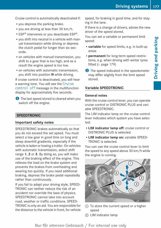
Cruise control is automatically deactivated if:Ryou depress the parking brake.Ryou are driving at less than 30 km/h.RESP® intervenes or you deactivate ESP®.Ryou shift into neutral in a vehicle with man-
ual transmission while driving or depressthe clutch pedal for longer than six sec-onds.Ron vehicles with manual transmission, you
shift to a gear that is too high, and as aresult the engine speed is too low.Ron vehicles with automatic transmission,
you shift into position N while driving.If cruise control is deactivated, you will heara warning tone. You will see the Cruise control off message in the multifunctiondisplay for approximately five seconds.
i The last speed stored is cleared when youswitch off the engine.
SPEEDTRONIC
Important safety notesSPEEDTRONIC brakes automatically so thatyou do not exceed the set speed. You mustselect a low gear in good time on long andsteep downhill gradients, especially if thevehicle is laden or towing a trailer. On vehicleswith automatic transmission, select shiftrange 1, 2 or 3. By doing so, you will makeuse of the braking effect of the engine. Thisrelieves the load on the brake system andprevents the brakes from overheating andwearing too quickly. If you need additionalbraking, depress the brake pedal repeatedlyrather than continuously.If you fail to adapt your driving style, SPEED-TRONIC can neither reduce the risk of anaccident nor override the laws of physics.SPEEDTRONIC cannot take into accountroad, weather or traffic conditions. SPEED-TRONIC is only an aid. You are responsible forthe distance to the vehicle in front, for vehicle
speed, for braking in good time, and for stay-ing in the lane.If there is a change of drivers, advise the newdriver of the speed stored.You can set a variable or permanent limitspeed:Rvariable for speed limits, e.g. in built-up
areasRpermanent for long-term speed restric-
tions, e.g. when driving with winter tyresfitted (Y page 179)
i The speed indicated in the speedometermay differ slightly from the limit speedstored.
Variable SPEEDTRONIC
General notesWith the cruise control lever, you can operatecruise control or DISTRONIC PLUS and vari-able SPEEDTRONIC.The LIM indicator lamp on the cruise controllever indicates which system you have selec-ted:RLIM indicator lamp off: cruise control or
DISTRONIC PLUS is selected.RLIM indicator lamp on: variable SPEED-
TRONIC is selected.You can use the cruise control lever to limitthe speed to any speed above 30 km/h whilethe engine is running.
: To store the current speed or a higherspeed
; LIM indicator lamp
Driving systems 177
Driv
ing
and
park
ing
Z
= To store the current speed and call up thelast stored speed
? To store the current speed or a lowerspeed
A To switch between cruise control and var-iable SPEEDTRONIC
B To deactivate variable SPEEDTRONIC
Selecting variable SPEEDTRONICX Check whether LIM indicator lamp ; is on.
If it is on, variable SPEEDTRONIC is alreadyselected.If it is not, press the cruise control lever inthe direction of arrow A.LIM indicator lamp ; in the cruise controllever lights up. Variable SPEEDTRONIC isselected.
Storing the current speedYou can use the cruise control lever to limitthe speed to any speed above 30 km/h whilethe engine is running.X Briefly press the cruise control lever to the
pressure point up : or down ?.The current speed is stored. For five sec-onds, the multifunction display shows thestored speed, e.g. Limit 100 km/h.Vehicles with the 4-button multifunctionsteering wheel: the stored speed is perma-nently displayed in the status indicator, e.g.LIM 100 km/h.Vehicles with a 12-button multifunctionsteering wheel: on the speedometer, thesegments from the start of the scale up tothe stored speed are lit up.
Storing the current speed and calling upthe last stored speedG WARNINGIf you call up the stored speed and it is lowerthan the current speed, the vehicle deceler-ates. If you do not know the stored speed, thevehicle could decelerate unexpectedly. Thereis a risk of an accident.
Pay attention to the road and traffic condi-tions before calling up the stored speed. If youdo not know the stored speed, store thedesired speed again.
X Briefly pull the cruise control lever towardsyou =.
Making adjustments in 1 km/h incre-mentsX Briefly press the cruise control lever to the
pressure point, up : for a higher speed ordown ? for a lower speed.
orX Keep the cruise control lever pressed to the
pressure point until the desired speed isset. Press the cruise control lever up : fora higher speed or down ? for a lowerspeed.
Making adjustments in 10 km/h incre-mentsX Briefly press the cruise control lever
beyond the pressure point, up : for ahigher speed or down ? for a lower speed.
orX Keep the cruise control lever pressed
beyond the pressure point until the desiredspeed is set. Press the cruise control leverup : for a higher speed or down ? for alower speed.
Deactivating variable SPEEDTRONICIt is not possible to deactivate variableSPEEDTRONIC by braking.There are several ways to deactivate variableSPEEDTRONIC:X Briefly press the cruise control lever for-
wards B.
orX Briefly press the cruise control lever in the
direction of arrow A.LIM indicator lamp ; in the cruise controllever goes out. Variable SPEEDTRONIC isdeactivated.
178 Driving systemsDr
ivin
g an
d pa
rkin
g
Cruise control is selected.Variable SPEEDTRONIC is automaticallydeactivated if:Ryou depress the accelerator pedal beyond
the pressure point (kickdown), but only ifyour current speed does not differ by morethan 20 km/h from the stored speed. Youwill hear a warning tone if this is the case.Ron vehicles with manual transmission, if
you shift to a higher gear and as a result,the engine speed is too low.
i The last speed stored is cleared when youswitch off the engine.
Permanent SPEEDTRONICYou can use the on-board computer to limitthe speed permanently to a value between160 km/h(e.g. for driving on winter tyres) andthe maximum speed (Y page 233).Shortly before the stored speed is reached, itappears in the multifunction display.Permanent SPEEDTRONIC remains active,even if variable SPEEDTRONIC is deactivated.You cannot exceed the stored limit speed,even if you depress the accelerator pedalbeyond the pressure point (kickdown).
DISTRONIC PLUS
Important safety notesDISTRONIC PLUS regulates the speed andautomatically helps you maintain the dis-tance to the vehicle detected in front. DIS-TRONIC PLUS brakes automatically so thatthe set speed is not exceeded.You must select a low gear in good time onlong and steep downhill gradients, especiallyif the vehicle is laden or towing a trailer. Onvehicles with automatic transmission, selectshift range 1, 2 or 3. By doing so, you willmake use of the braking effect of the engine.This relieves the load on the brake system andprevents the brakes from overheating andwearing too quickly.
If DISTRONIC PLUS detects a slower-movingvehicle in front, your vehicle is braked in orderto maintain the preset distance to the vehiclein front.
G WARNINGDISTRONIC PLUS does not react to:Rpeople or animalsRstationary obstacles on the road, e.g. stop-
ped or parked vehiclesRoncoming and crossing trafficAs a result, DISTRONIC PLUS may neither givewarnings nor intervene in such situations.There is a risk of an accident.Always pay careful attention to the traffic sit-uation and be ready to brake.
G WARNINGDISTRONIC PLUS cannot always clearly iden-tify other road users and complex traffic sit-uations.In such cases, DISTRONIC PLUS may:Rgive an unnecessary warning and then
brake the vehicleRneither give a warning nor interveneRaccelerate unexpectedlyThere is a risk of an accident.Continue to drive carefully and be ready tobrake, in particular when warned to do so byDISTRONIC PLUS.
G WARNINGDISTRONIC PLUS brakes your vehicle with upto 40% of the maximum braking force. If thisbraking force is insufficient, DISTRONIC PLUSwarns you visually and audibly. There is a riskof an accident.In such cases, apply the brakes yourself andtry to take evasive action.
Driving systems 179
Driv
ing
and
park
ing
Z
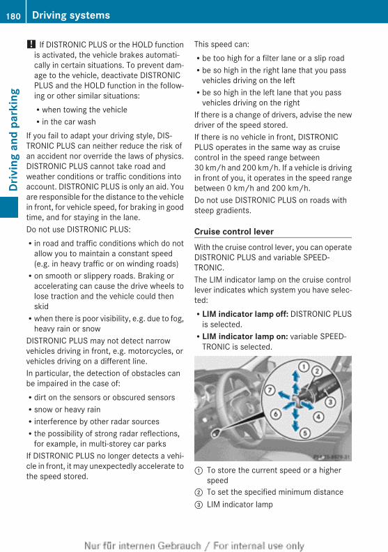
! If DISTRONIC PLUS or the HOLD functionis activated, the vehicle brakes automati-cally in certain situations. To prevent dam-age to the vehicle, deactivate DISTRONICPLUS and the HOLD function in the follow-ing or other similar situations:Rwhen towing the vehicleRin the car wash
If you fail to adapt your driving style, DIS-TRONIC PLUS can neither reduce the risk ofan accident nor override the laws of physics.DISTRONIC PLUS cannot take road andweather conditions or traffic conditions intoaccount. DISTRONIC PLUS is only an aid. Youare responsible for the distance to the vehiclein front, for vehicle speed, for braking in goodtime, and for staying in the lane.Do not use DISTRONIC PLUS:Rin road and traffic conditions which do not
allow you to maintain a constant speed(e.g. in heavy traffic or on winding roads)Ron smooth or slippery roads. Braking or
accelerating can cause the drive wheels tolose traction and the vehicle could thenskidRwhen there is poor visibility, e.g. due to fog,
heavy rain or snowDISTRONIC PLUS may not detect narrowvehicles driving in front, e.g. motorcycles, orvehicles driving on a different line.In particular, the detection of obstacles canbe impaired in the case of:Rdirt on the sensors or obscured sensorsRsnow or heavy rainRinterference by other radar sourcesRthe possibility of strong radar reflections,
for example, in multi-storey car parksIf DISTRONIC PLUS no longer detects a vehi-cle in front, it may unexpectedly accelerate tothe speed stored.
This speed can:Rbe too high for a filter lane or a slip roadRbe so high in the right lane that you pass
vehicles driving on the leftRbe so high in the left lane that you pass
vehicles driving on the rightIf there is a change of drivers, advise the newdriver of the speed stored.If there is no vehicle in front, DISTRONICPLUS operates in the same way as cruisecontrol in the speed range between30 km/h and 200 km/h. If a vehicle is drivingin front of you, it operates in the speed rangebetween 0 km/h and 200 km/h.Do not use DISTRONIC PLUS on roads withsteep gradients.
Cruise control leverWith the cruise control lever, you can operateDISTRONIC PLUS and variable SPEED-TRONIC.The LIM indicator lamp on the cruise controllever indicates which system you have selec-ted:RLIM indicator lamp off: DISTRONIC PLUS
is selected.RLIM indicator lamp on: variable SPEED-
TRONIC is selected.
: To store the current speed or a higherspeed
; To set the specified minimum distance= LIM indicator lamp
180 Driving systemsDr
ivin
g an
d pa
rkin
g
? To store the current speed and call up thelast stored speed
A To store the current speed or a lowerspeed
B To switch between DISTRONIC PLUS andvariable SPEEDTRONIC
C To deactivate DISTRONIC PLUS
Selecting DISTRONIC PLUSX Check whether LIM indicator lamp = is off.
If it is off, DISTRONIC PLUS is already selec-ted.If it is not, press the cruise control lever inthe direction of arrow B.LIM indicator lamp = in the cruise controllever goes out. DISTRONIC PLUS is selec-ted.
Activating DISTRONIC PLUS, storingand maintaining the current speed
Activation conditionsTo activate DISTRONIC PLUS, the followingconditions must be fulfilled:Rthe engine must be running. It may take up
to two minutes of driving before DIS-TRONIC PLUS is ready for use.Rthe parking brake must be released.RESP® must be switched on, but not inter-
vening.Rthe transmission must be in position D.Rthe bonnet must be closed.Rthe driver's door must be closed when you
shift from P to D or your seat belt must befastened.Rthe front-passenger door must be closed.Rthe vehicle must not be skidding.
Activating while drivingWhen driving at speeds below 30 km/h, youcan only activate DISTRONIC PLUS if the vehi-cle in front has been detected and is shownin the multifunction display. If the vehicle infront is no longer detected and displayed,
DISTRONIC PLUS switches off and you willhear a tone.X Briefly pull the cruise control lever towards
you ?, or press it up : or down A.DISTRONIC PLUS is activated.
X Keep the cruise control lever pressedup : or down A until the desired speedis set.
X Remove your foot from the acceleratorpedal.Your vehicle adapts its speed to that of thevehicle in front, but only up to the desiredstored speed.
i If you do not fully release the acceleratorpedal, the DISTRONIC PLUS inactivemessage appears in the multifunction dis-play. The set distance to a slower-movingvehicle in front will then not be maintained.You will be driving at the speed you deter-mine by the position of the acceleratorpedal.
Activating when driving towards a sta-tionary vehicleIf the vehicle in front of you is stationary, youcan only activate DISTRONIC PLUS once yourvehicle is stationary as well.X Briefly pull the cruise control lever towards
you ?, or press it up : or down A.DISTRONIC PLUS is activated.
i DISTRONIC PLUS can only be activated atunder 30 km/h if a vehicle in front has beendetected. For this reason, it is helpful if youhave the DISTRONIC PLUS distance displayshown in the instrument cluster(Y page 228).
X Keep the cruise control lever pressedup : or down A until the desired speedis set.
i You can use the cruise control lever to setthe stored speed and the control on thecruise control lever to set the specifiedminimum distance (Y page 184).
Driving systems 181
Driv
ing
and
park
ing
Z
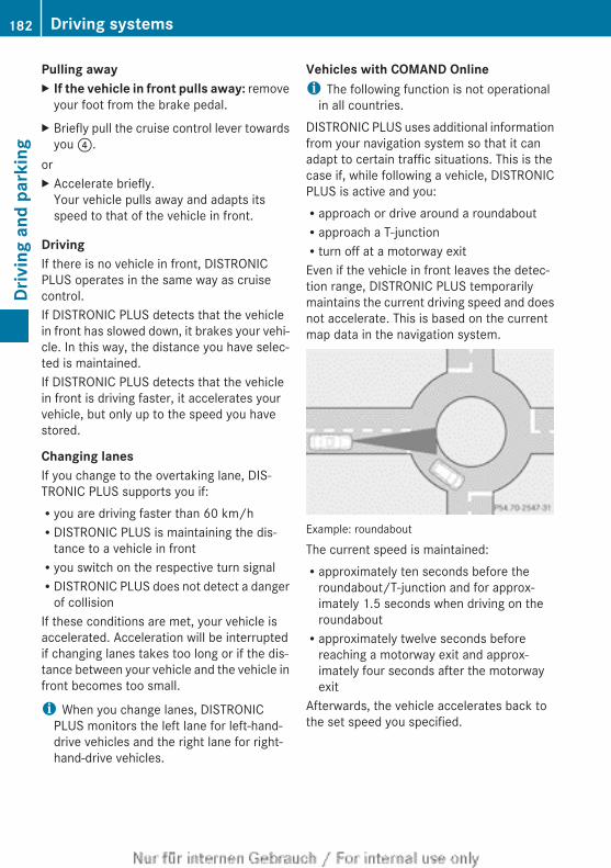
Pulling awayX If the vehicle in front pulls away: remove
your foot from the brake pedal.X Briefly pull the cruise control lever towards
you ?.orX Accelerate briefly.
Your vehicle pulls away and adapts itsspeed to that of the vehicle in front.
DrivingIf there is no vehicle in front, DISTRONICPLUS operates in the same way as cruisecontrol.If DISTRONIC PLUS detects that the vehiclein front has slowed down, it brakes your vehi-cle. In this way, the distance you have selec-ted is maintained.If DISTRONIC PLUS detects that the vehiclein front is driving faster, it accelerates yourvehicle, but only up to the speed you havestored.
Changing lanesIf you change to the overtaking lane, DIS-TRONIC PLUS supports you if:Ryou are driving faster than 60 km/hRDISTRONIC PLUS is maintaining the dis-
tance to a vehicle in frontRyou switch on the respective turn signalRDISTRONIC PLUS does not detect a danger
of collisionIf these conditions are met, your vehicle isaccelerated. Acceleration will be interruptedif changing lanes takes too long or if the dis-tance between your vehicle and the vehicle infront becomes too small.
i When you change lanes, DISTRONICPLUS monitors the left lane for left-hand-drive vehicles and the right lane for right-hand-drive vehicles.
Vehicles with COMAND Onlinei The following function is not operational
in all countries.DISTRONIC PLUS uses additional informationfrom your navigation system so that it canadapt to certain traffic situations. This is thecase if, while following a vehicle, DISTRONICPLUS is active and you:Rapproach or drive around a roundaboutRapproach a T-junctionRturn off at a motorway exitEven if the vehicle in front leaves the detec-tion range, DISTRONIC PLUS temporarilymaintains the current driving speed and doesnot accelerate. This is based on the currentmap data in the navigation system.
Example: roundabout
The current speed is maintained:Rapproximately ten seconds before the
roundabout/T-junction and for approx-imately 1.5 seconds when driving on theroundaboutRapproximately twelve seconds before
reaching a motorway exit and approx-imately four seconds after the motorwayexit
Afterwards, the vehicle accelerates back tothe set speed you specified.
182 Driving systemsDr
ivin
g an
d pa
rkin
g
StoppingG WARNINGWhen leaving the vehicle, even if it is brakedonly by DISTRONIC PLUS, it could roll away if:Rthere is a malfunction in the system or in
the voltage supply.RDISTRONIC PLUS has been deactivated
with the cruise control lever, e.g. by a vehi-cle occupant or from outside the vehicle.Rthe electrical system in the engine com-
partment, the battery or the fuses havebeen tampered with.Rthe battery is disconnected.Rthe accelerator pedal has been depressed,
e.g. by a vehicle occupant.There is a risk of an accident.If you wish to exit the vehicle, always turn offDISTRONIC PLUS and secure the vehicleagainst rolling away.
Deactivating DISTRONIC PLUS(Y page 185).If DISTRONIC PLUS detects that the vehiclein front is stopping, it brakes your vehicle untilit is stationary.Once your vehicle is stationary, it remainsstationary and you do not need to depress thebrake.
i Depending on the specified minimum dis-tance, your vehicle will come to a standstillat a sufficient distance behind the vehiclein front. The specified minimum distance isset using the control on the cruise controllever.
You will see a warning message in the multi-function display if DISTRONIC PLUS is acti-vated and:Rthe driver's door is open and the driver's
seat belt is unfastenedRthe engine is switched off, unless it is auto-
matically switched off by the ECO start/stop functionRthe bonnet is openedSelect Park (P)
X Shift the transmission to position P to pre-vent the vehicle from rolling away.DISTRONIC PLUS is deactivated. The warn-ing message in the multifunction displaydisappears.
The horn will also sound at regular intervals ifDISTRONIC PLUS is activated and you:Rswitch the engine off, open the driver's
door and take off your seat beltRopen the bonnetThe sounding of the horn alerts you to the factthat the vehicle has been parked while DIS-TRONIC PLUS is still activated. The soundbecomes louder if you attempt to lock thevehicle. The vehicle is not locked until DIS-TRONIC PLUS is deactivated.
i If the engine has been switched off, itcannot be started again until DISTRONICPLUS has been deactivated.
If DISTRONIC PLUS is activated and a faultoccurs in the system or if there is a disruptionin the voltage supply, the Brake immedi‐ately message is shown in the multifunctiondisplay. Immediately depress the brake firmlyuntil the warning message in the multifunc-tion display goes out or shift the transmissionto position P. DISTRONIC PLUS is deactiva-ted.
Setting a speedX Press the cruise control lever up : for a
higher speed or down A for a lower speed.X Keep the cruise control lever pressed until
the desired speed is reached.X Release the cruise control lever.
The new speed is stored. DISTRONIC PLUSis activated and adjusts the vehicle's speedto the new speed stored.
X To adjust the set speed in 1 km/h incre-ments: briefly press the cruise control
Driving systems 183
Driv
ing
and
park
ing
Z
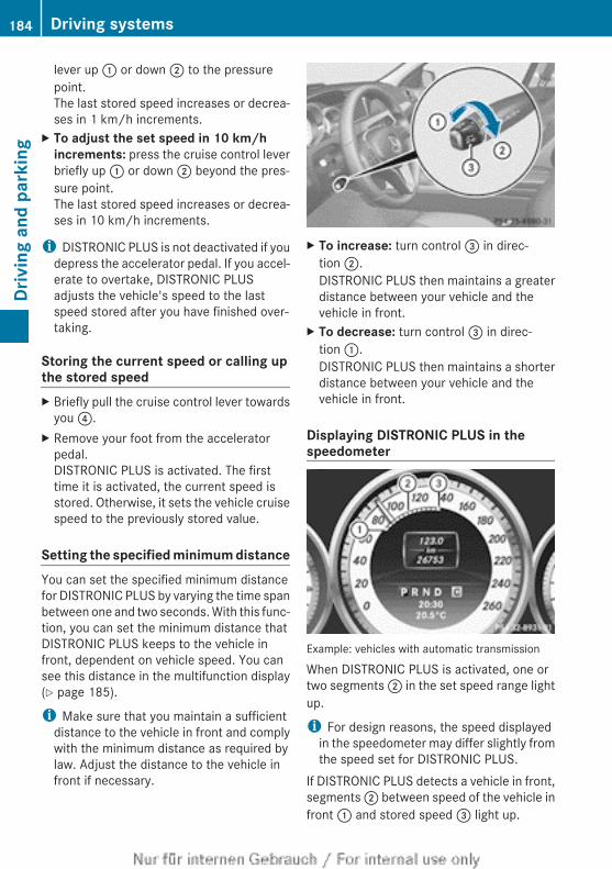
lever up : or down ; to the pressurepoint.The last stored speed increases or decrea-ses in 1 km/h increments.
X To adjust the set speed in 10 km/h increments: press the cruise control leverbriefly up : or down ; beyond the pres-sure point.The last stored speed increases or decrea-ses in 10 km/h increments.
i DISTRONIC PLUS is not deactivated if youdepress the accelerator pedal. If you accel-erate to overtake, DISTRONIC PLUSadjusts the vehicle's speed to the lastspeed stored after you have finished over-taking.
Storing the current speed or calling upthe stored speedX Briefly pull the cruise control lever towards
you ?.X Remove your foot from the accelerator
pedal.DISTRONIC PLUS is activated. The firsttime it is activated, the current speed isstored. Otherwise, it sets the vehicle cruisespeed to the previously stored value.
Setting the specified minimum distanceYou can set the specified minimum distancefor DISTRONIC PLUS by varying the time spanbetween one and two seconds. With this func-tion, you can set the minimum distance thatDISTRONIC PLUS keeps to the vehicle infront, dependent on vehicle speed. You cansee this distance in the multifunction display(Y page 185).
i Make sure that you maintain a sufficientdistance to the vehicle in front and complywith the minimum distance as required bylaw. Adjust the distance to the vehicle infront if necessary.
X To increase: turn control = in direc-tion ;.DISTRONIC PLUS then maintains a greaterdistance between your vehicle and thevehicle in front.
X To decrease: turn control = in direc-tion :.DISTRONIC PLUS then maintains a shorterdistance between your vehicle and thevehicle in front.
Displaying DISTRONIC PLUS in thespeedometer
Example: vehicles with automatic transmission
When DISTRONIC PLUS is activated, one ortwo segments ; in the set speed range lightup.
i For design reasons, the speed displayedin the speedometer may differ slightly fromthe speed set for DISTRONIC PLUS.
If DISTRONIC PLUS detects a vehicle in front,segments ; between speed of the vehicle infront : and stored speed = light up.
184 Driving systemsDr
ivin
g an
d pa
rkin
g
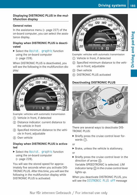
Displaying DISTRONIC PLUS in the mul-tifunction display
General notesIn the assistance menu (Y page 227) of theon-board computer, you can select the assis-tance display.
Display when DISTRONIC PLUS is deacti-vatedX Select the Assist. graphic function
using the on-board computer(Y page 228).
When DISTRONIC PLUS is deactivated, youwill see the following in the multifunction dis-play:
Example: vehicles with automatic transmission: Vehicle in front, if detected; Distance indicator: current distance to
the vehicle in front= Specified minimum distance to the vehi-
cle in front; adjustable? Own vehicle
Display when DISTRONIC PLUS is activa-tedX Select the Assist. graphic function
using the on-board computer(Y page 228).
You will see the stored speed for approx-imately five seconds when you activate DIS-TRONIC PLUS. After this time, you will see thefollowing in the multifunction display whileDISTRONIC PLUS is activated:
Example: vehicles with automatic transmission: Vehicle in front, if detected; Specified minimum distance to the vehi-
cle in front; adjustable= Own vehicle? DISTRONIC PLUS activated
Deactivating DISTRONIC PLUS
There are several ways to deactivate DIS-TRONIC PLUS:X Briefly press the cruise control lever for-
wards :.orX Brake, unless the vehicle is stationary.orX Briefly press the cruise control lever in the
direction of arrow =.Variable SPEEDTRONIC is selected. LIMindicator lamp ; in the cruise control leverlights up.
When you deactivate DISTRONIC PLUS, youwill see the DISTRONIC PLUS off message
Driving systems 185
Driv
ing
and
park
ing
Z
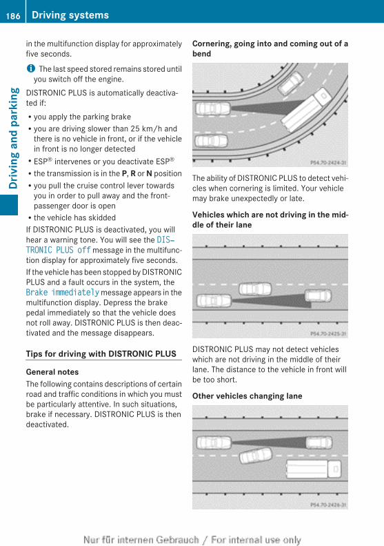
in the multifunction display for approximatelyfive seconds.
i The last speed stored remains stored untilyou switch off the engine.
DISTRONIC PLUS is automatically deactiva-ted if:Ryou apply the parking brakeRyou are driving slower than 25 km/h and
there is no vehicle in front, or if the vehiclein front is no longer detectedRESP® intervenes or you deactivate ESP®
Rthe transmission is in the P, R or N positionRyou pull the cruise control lever towards
you in order to pull away and the front-passenger door is openRthe vehicle has skiddedIf DISTRONIC PLUS is deactivated, you willhear a warning tone. You will see the DIS‐TRONIC PLUS off message in the multifunc-tion display for approximately five seconds.If the vehicle has been stopped by DISTRONICPLUS and a fault occurs in the system, theBrake immediately message appears in themultifunction display. Depress the brakepedal immediately so that the vehicle doesnot roll away. DISTRONIC PLUS is then deac-tivated and the message disappears.
Tips for driving with DISTRONIC PLUS
General notesThe following contains descriptions of certainroad and traffic conditions in which you mustbe particularly attentive. In such situations,brake if necessary. DISTRONIC PLUS is thendeactivated.
Cornering, going into and coming out of abend
The ability of DISTRONIC PLUS to detect vehi-cles when cornering is limited. Your vehiclemay brake unexpectedly or late.
Vehicles which are not driving in the mid-dle of their lane
DISTRONIC PLUS may not detect vehicleswhich are not driving in the middle of theirlane. The distance to the vehicle in front willbe too short.
Other vehicles changing lane
186 Driving systemsDr
ivin
g an
d pa
rkin
g
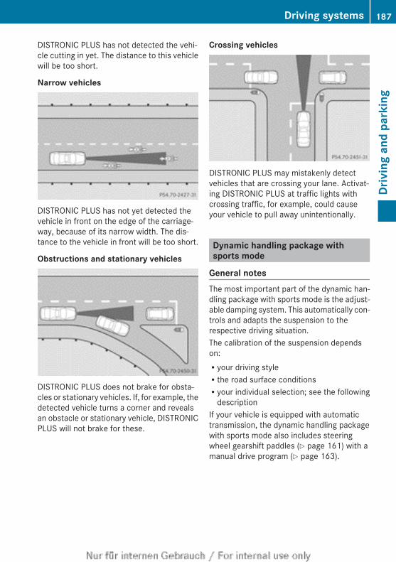
DISTRONIC PLUS has not detected the vehi-cle cutting in yet. The distance to this vehiclewill be too short.
Narrow vehicles
DISTRONIC PLUS has not yet detected thevehicle in front on the edge of the carriage-way, because of its narrow width. The dis-tance to the vehicle in front will be too short.
Obstructions and stationary vehicles
DISTRONIC PLUS does not brake for obsta-cles or stationary vehicles. If, for example, thedetected vehicle turns a corner and revealsan obstacle or stationary vehicle, DISTRONICPLUS will not brake for these.
Crossing vehicles
DISTRONIC PLUS may mistakenly detectvehicles that are crossing your lane. Activat-ing DISTRONIC PLUS at traffic lights withcrossing traffic, for example, could causeyour vehicle to pull away unintentionally.
Dynamic handling package withsports mode
General notesThe most important part of the dynamic han-dling package with sports mode is the adjust-able damping system. This automatically con-trols and adapts the suspension to therespective driving situation.The calibration of the suspension dependson:Ryour driving styleRthe road surface conditionsRyour individual selection; see the following
descriptionIf your vehicle is equipped with automatictransmission, the dynamic handling packagewith sports mode also includes steeringwheel gearshift paddles (Y page 161) with amanual drive program (Y page 163).
Driving systems 187
Driv
ing
and
park
ing
Z
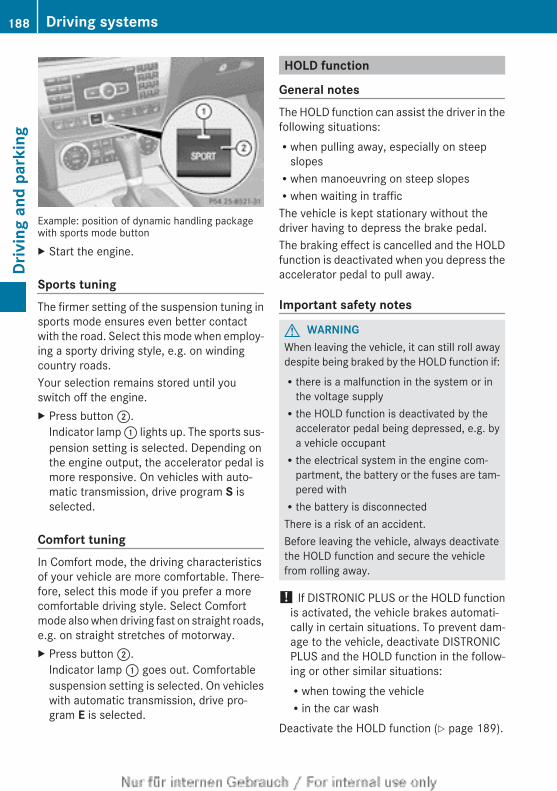
Example: position of dynamic handling packagewith sports mode buttonX Start the engine.
Sports tuningThe firmer setting of the suspension tuning insports mode ensures even better contactwith the road. Select this mode when employ-ing a sporty driving style, e.g. on windingcountry roads.Your selection remains stored until youswitch off the engine.X Press button ;.
Indicator lamp : lights up. The sports sus-pension setting is selected. Depending onthe engine output, the accelerator pedal ismore responsive. On vehicles with auto-matic transmission, drive program S isselected.
Comfort tuningIn Comfort mode, the driving characteristicsof your vehicle are more comfortable. There-fore, select this mode if you prefer a morecomfortable driving style. Select Comfortmode also when driving fast on straight roads,e.g. on straight stretches of motorway.X Press button ;.
Indicator lamp : goes out. Comfortablesuspension setting is selected. On vehicleswith automatic transmission, drive pro-gram E is selected.
HOLD function
General notesThe HOLD function can assist the driver in thefollowing situations:Rwhen pulling away, especially on steep
slopesRwhen manoeuvring on steep slopesRwhen waiting in trafficThe vehicle is kept stationary without thedriver having to depress the brake pedal.The braking effect is cancelled and the HOLDfunction is deactivated when you depress theaccelerator pedal to pull away.
Important safety notes
G WARNINGWhen leaving the vehicle, it can still roll awaydespite being braked by the HOLD function if:Rthere is a malfunction in the system or in
the voltage supplyRthe HOLD function is deactivated by the
accelerator pedal being depressed, e.g. bya vehicle occupantRthe electrical system in the engine com-
partment, the battery or the fuses are tam-pered withRthe battery is disconnectedThere is a risk of an accident.Before leaving the vehicle, always deactivatethe HOLD function and secure the vehiclefrom rolling away.
! If DISTRONIC PLUS or the HOLD functionis activated, the vehicle brakes automati-cally in certain situations. To prevent dam-age to the vehicle, deactivate DISTRONICPLUS and the HOLD function in the follow-ing or other similar situations:Rwhen towing the vehicleRin the car wash
Deactivate the HOLD function (Y page 189).
188 Driving systemsDr
ivin
g an
d pa
rkin
g
Activation conditionsYou can activate the HOLD function if:Rthe vehicle is stationary.Rthe engine is running or if it has been auto-
matically switched off by the ECO start/stop function.Rthe driver's door is closed or if your seat
belt is fastened.Rthe parking brake is released.Rthe bonnet is closed.Rthe selector lever is in position D, R or N on
vehicles with automatic transmission.RDISTRONIC PLUS is deactivated.
Activating the HOLD functionX Make sure that the activation conditions
are met.X Depress the brake pedal.X Quickly depress the brake pedal further
until ë appears in the multifunction dis-play.The HOLD function is activated. You canrelease the brake pedal.
i If depressing the brake pedal the firsttime does not activate the HOLD function,wait briefly and then try again.
Deactivating the HOLD functionThe HOLD function is deactivated automati-cally if:Ryou accelerate. On vehicles with automatic
transmission: only when the transmissionis in position D or R.Rthe transmission is in position P on vehicles
with automatic transmission.Ryou depress the brake pedal again with a
certain amount of pressure until ë dis-appears from the multifunction display.Ryou activate DISTRONIC PLUS.You will see a warning message in the multi-function display if the HOLD function is acti-vated and:
Rthe driver's door is open and the driver'sseat belt is unfastenedRthe engine is switched off, unless it is auto-
matically switched off by the ECO start/stop functionRthe bonnet is openedVehicles with manual transmission:Brake immediatelyX Immediately depress the brake pedal firmly
until the warning message in the multifunc-tion display goes out. This deactivates theHOLD function.
In vehicles with automatic transmission:Select Park (P).X Shift the transmission to position P to pre-
vent the vehicle from rolling away.The HOLD function is deactivated. Thewarning message in the multifunction dis-play disappears.
A horn will also sound at regular intervals ifthe HOLD function is activated and you:Rswitch the engine off, open the driver's
door and take off your seat beltRopen the bonnetThe sounding of the horn alerts you to the factthat the vehicle has been parked while theHOLD function is still activated. If you attemptto lock the vehicle, the tone becomes louder.The vehicle is not locked until the HOLD func-tion is deactivated.
i If the engine has been switched off, itcannot be started again until the HOLDfunction has been deactivated.
If there is a fault in the system or power supplywhile the HOLD function is activated, theBrake immediately message is shown inthe multifunction display. Immediatelydepress the brake firmly until the warningmessage in the multifunction display goesout.On vehicles with automatic transmission, youcan also shift into position P. This deactivatesthe HOLD function.
Driving systems 189
Driv
ing
and
park
ing
Z
RACE START
Important safety notesi Observe the safety notes for the SPORT
handling mode (Y page 75).Only activate RACE START on dedicated racecircuits. Always adapt your speed and drivingstyle to the prevailing road and weather con-ditions.RACE START enables optimum accelerationfrom a standing start. The precondition forthis is a suitable high-grip road surface.
i RACE START is only available in AMG vehi-cles.
Activation conditionsYou can activate RACE START if:Rthe doors are closed.Rthe engine is running and it has reached an
operating temperature of approximately80 †. This is the case when the engine oiltemperature in the multifunction displaystops flashing.RSPORT handling mode is activated
(Y page 75).Rthe steering wheel is in the straight-ahead
position.Rthe vehicle is stationary and the brake
pedal is depressed (left foot).Rthe transmission is in position D.
Activating RACE STARTX Depress the brake pedal with your left foot
and keep it depressed.X Turn the drive program selector clockwise
(Y page 160) until the RS lamp lights up.The RACE START Confirm: Paddle UP Cancel: Paddle DOWN message appearsin the multifunction display.
i If the activation conditions are no longerfulfilled, RACE START is cancelled. The mul-tifunction display shows the RACE START cancelled message.
X To cancel: pull the left steering wheel shiftpaddle (Y page 161).
orX To confirm: pull the right steering wheel
shift paddle (Y page 161).The RACE START available Depress accelerator message appears in the mul-tifunction display.
i If you do not depress the acceleratorpedal fully within two seconds, RACESTART is cancelled. The RACE START not possible See Owner's Manual messageappears in the multifunction display.
X Fully depress the accelerator pedal.The engine speed rises to approximately3,500 rpm.The RACE START Release brake to start message appears in the multifunc-tion display.
i If you do not release the brake pedalwithin five seconds, RACE START is cancel-led. The multifunction display shows theRACE START cancelled message.
X Take your foot off the brake, but keep theaccelerator pedal depressed.The vehicle pulls away at maximum accel-eration.The RACE START active message appearsin the multifunction display.
RACE START is deactivated when the vehiclereaches a speed of approximately 50 km/h.Drive program S+ is activated. SPORT han-dling mode remains activated.RACE START is deactivated immediately ifyou release the accelerator pedal duringRACE START or if any of the activation condi-tions are no longer fulfilled. The RACE START not possible See Owner's Manual mes-sage appears in the multifunction display.
i After using it several times in short suc-cession, RACE START will be unavailableuntil a certain distance has been driven.
190 Driving systemsDr
ivin
g an
d pa
rkin
g
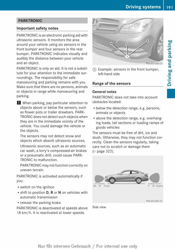
PARKTRONIC
Important safety notesPARKTRONIC is an electronic parking aid withultrasonic sensors. It monitors the areaaround your vehicle using six sensors in thefront bumper and four sensors in the rearbumper. PARKTRONIC indicates visually andaudibly the distance between your vehicleand an object.PARKTRONIC is only an aid. It is not a substi-tute for your attention to the immediate sur-roundings. The responsibility for safemanoeuvring and parking remains with you.Make sure that there are no persons, animalsor objects in range while manoeuvring andparking.
! When parking, pay particular attention toobjects above or below the sensors, suchas flower pots or trailer drawbars. PARK-TRONIC does not detect such objects whenthey are in the immediate vicinity of thevehicle. You could damage the vehicle orthe objects.The sensors may not detect snow andobjects which absorb ultrasonic sources.Ultrasonic sources, such as an automaticcar wash, a lorry's compressed-air brakesor a pneumatic drill, could cause PARK-TRONIC to malfunction.PARKTRONIC may not function correctly onuneven terrain.
PARKTRONIC is activated automatically ifyou:Rswitch on the ignitionRshift to position D, R or N on vehicles with
automatic transmissionRrelease the parking brakePARKTRONIC is deactivated at speeds above18 km/h. It is reactivated at lower speeds.
: Example: sensors in the front bumper,left-hand side
Range of the sensors
General notesPARKTRONIC does not take into accountobstacles located:Rbelow the detection range, e.g. persons,
animals or objectsRabove the detection range, e.g. overhang-
ing loads, tail sections or loading ramps ofgoods vehicles
The sensors must be free of dirt, ice andslush. Otherwise, they may not function cor-rectly. Clean the sensors regularly, takingcare not to scratch or damage them(Y page 322).
Side view
Driving systems 191
Driv
ing
and
park
ing
Z
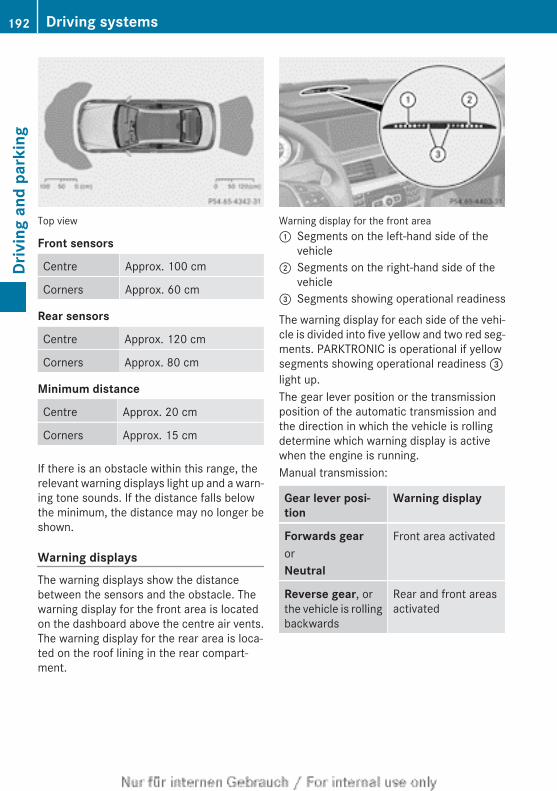
Top view
Front sensors
Centre Approx. 100 cm
Corners Approx. 60 cm
Rear sensors
Centre Approx. 120 cm
Corners Approx. 80 cm
Minimum distance
Centre Approx. 20 cm
Corners Approx. 15 cm
If there is an obstacle within this range, therelevant warning displays light up and a warn-ing tone sounds. If the distance falls belowthe minimum, the distance may no longer beshown.
Warning displaysThe warning displays show the distancebetween the sensors and the obstacle. Thewarning display for the front area is locatedon the dashboard above the centre air vents.The warning display for the rear area is loca-ted on the roof lining in the rear compart-ment.
Warning display for the front area: Segments on the left-hand side of the
vehicle; Segments on the right-hand side of the
vehicle= Segments showing operational readiness
The warning display for each side of the vehi-cle is divided into five yellow and two red seg-ments. PARKTRONIC is operational if yellowsegments showing operational readiness =light up.The gear lever position or the transmissionposition of the automatic transmission andthe direction in which the vehicle is rollingdetermine which warning display is activewhen the engine is running.Manual transmission:
Gear lever posi-tion
Warning display
Forwards gearorNeutral
Front area activated
Reverse gear, orthe vehicle is rollingbackwards
Rear and front areasactivated
192 Driving systemsDr
ivin
g an
d pa
rkin
g
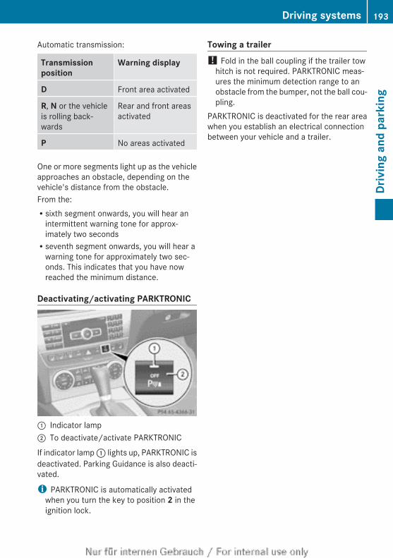
Automatic transmission:
Transmission position
Warning display
D Front area activated
R, N or the vehicleis rolling back-wards
Rear and front areasactivated
P No areas activated
One or more segments light up as the vehicleapproaches an obstacle, depending on thevehicle's distance from the obstacle.From the:Rsixth segment onwards, you will hear an
intermittent warning tone for approx-imately two secondsRseventh segment onwards, you will hear a
warning tone for approximately two sec-onds. This indicates that you have nowreached the minimum distance.
Deactivating/activating PARKTRONIC
: Indicator lamp; To deactivate/activate PARKTRONIC
If indicator lamp : lights up, PARKTRONIC isdeactivated. Parking Guidance is also deacti-vated.
i PARKTRONIC is automatically activatedwhen you turn the key to position 2 in theignition lock.
Towing a trailer! Fold in the ball coupling if the trailer tow
hitch is not required. PARKTRONIC meas-ures the minimum detection range to anobstacle from the bumper, not the ball cou-pling.
PARKTRONIC is deactivated for the rear areawhen you establish an electrical connectionbetween your vehicle and a trailer.
Driving systems 193
Driv
ing
and
park
ing
Z
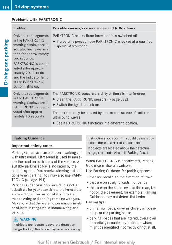
Problems with PARKTRONIC
Problem Possible causes/consequences and M Solutions
Only the red segmentsin the PARKTRONICwarning displays are lit.You also hear a warningtone for approximatelytwo seconds.PARKTRONIC is deacti-vated after approx-imately 20 seconds,and the indicator lampin the PARKTRONICbutton lights up.
PARKTRONIC has malfunctioned and has switched off.X If problems persist, have PARKTRONIC checked at a qualified
specialist workshop.
Only the red segmentsin the PARKTRONICwarning displays are lit.PARKTRONIC is deacti-vated after approx-imately 20 seconds.
The PARKTRONIC sensors are dirty or there is interference.X Clean the PARKTRONIC sensors (Y page 322).X Switch the ignition back on.
The problem may be caused by an external source of radio orultrasound waves.X See if PARKTRONIC functions in a different location.
Parking Guidance
Important safety notesParking Guidance is an electronic parking aidwith ultrasound. Ultrasound is used to meas-ure the road on both sides of the vehicle. Asuitable parking space is indicated by theparking symbol. You receive steering instruc-tions when parking. You may also use PARK-TRONIC (Y page 191).Parking Guidance is only an aid. It is not asubstitute for your attention to the immediatesurroundings. The responsibility for safemanoeuvring and parking remains with you.Make sure that there are no persons, animalsor objects in range while manoeuvring andparking.
G WARNINGIf objects are located above the detectionrange, Parking Guidance may provide steering
instructions too soon. This could cause a col-lision. There is a risk of an accident.If objects are located above the detectionrange, stop and switch off Parking Assist.
When PARKTRONIC is deactivated, ParkingGuidance is also unavailable.Use Parking Guidance for parking spaces:Rthat are parallel to the direction of travelRthat are on straight roads, not bendsRthat are on the same level as the road, i.e.
not on the pavement, for example. ParkingGuidance may not detect flat kerbs
Parking tips:Ron narrow roads, drive as closely as possi-
ble past the parking space.Rparking spaces that are littered, overgrown
or partially occupied by trailer drawbarsmight be identified incorrectly or not at all.
194 Driving systemsDr
ivin
g an
d pa
rkin
g
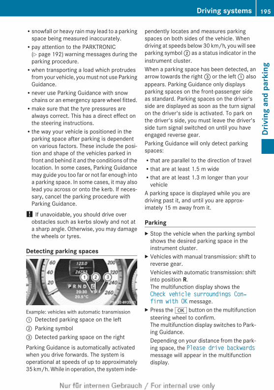
Rsnowfall or heavy rain may lead to a parkingspace being measured inaccurately.Rpay attention to the PARKTRONIC
(Y page 192) warning messages during theparking procedure.Rwhen transporting a load which protrudes
from your vehicle, you must not use ParkingGuidance.Rnever use Parking Guidance with snow
chains or an emergency spare wheel fitted.Rmake sure that the tyre pressures are
always correct. This has a direct effect onthe steering instructions.Rthe way your vehicle is positioned in the
parking space after parking is dependenton various factors. These include the posi-tion and shape of the vehicles parked infront and behind it and the conditions of thelocation. In some cases, Parking Guidancemay guide you too far or not far enough intoa parking space. In some cases, it may alsolead you across or onto the kerb. If neces-sary, cancel the parking procedure withParking Guidance.
! If unavoidable, you should drive overobstacles such as kerbs slowly and not ata sharp angle. Otherwise, you may damagethe wheels or tyres.
Detecting parking spaces
Example: vehicles with automatic transmission: Detected parking space on the left; Parking symbol= Detected parking space on the right
Parking Guidance is automatically activatedwhen you drive forwards. The system isoperational at speeds of up to approximately35 km/h. While in operation, the system inde-
pendently locates and measures parkingspaces on both sides of the vehicle. Whendriving at speeds below 30 km/h, you will seeparking symbol ; as a status indicator in theinstrument cluster.When a parking space has been detected, anarrow towards the right = or the left : alsoappears. Parking Guidance only displaysparking spaces on the front-passenger sideas standard. Parking spaces on the driver'sside are displayed as soon as the turn signalon the driver's side is activated. To park onthe driver's side, you must leave the driver'sside turn signal switched on until you haveengaged reverse gear.Parking Guidance will only detect parkingspaces:Rthat are parallel to the direction of travelRthat are at least 1.5 m wideRthat are at least 1.3 m longer than your
vehicleA parking space is displayed while you aredriving past it, and until you are approx-imately 15 m away from it.
ParkingX Stop the vehicle when the parking symbol
shows the desired parking space in theinstrument cluster.
X Vehicles with manual transmission: shift toreverse gear.Vehicles with automatic transmission: shiftinto position R.The multifunction display shows theCheck vehicle surroundings Con‐firm with OK message.
X Press the a button on the multifunctionsteering wheel to confirm.The multifunction display switches to Park-ing Guidance.Depending on your distance from the park-ing space, the Please drive backwardsmessage will appear in the multifunctiondisplay.
Driving systems 195
Driv
ing
and
park
ing
Z
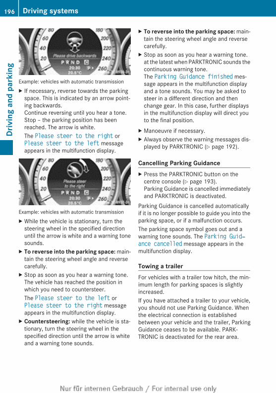
Example: vehicles with automatic transmissionX If necessary, reverse towards the parking
space. This is indicated by an arrow point-ing backwards.Continue reversing until you hear a tone.Stop – the parking position has beenreached. The arrow is white.The Please steer to the right orPlease steer to the left messageappears in the multifunction display.
Example: vehicles with automatic transmissionX While the vehicle is stationary, turn the
steering wheel in the specified directionuntil the arrow is white and a warning tonesounds.
X To reverse into the parking space: main-tain the steering wheel angle and reversecarefully.
X Stop as soon as you hear a warning tone.The vehicle has reached the position inwhich you need to countersteer.The Please steer to the left orPlease steer to the right messageappears in the multifunction display.
X Countersteering: while the vehicle is sta-tionary, turn the steering wheel in thespecified direction until the arrow is whiteand a warning tone sounds.
X To reverse into the parking space: main-tain the steering wheel angle and reversecarefully.
X Stop as soon as you hear a warning tone.at the latest when PARKTRONIC sounds thecontinuous warning tone.The Parking Guidance finished mes-sage appears in the multifunction displayand a tone sounds. You may be asked tosteer in a different direction and thenchange gear. In this case, further displaysin the multifunction display will direct youto the final position.
X Manoeuvre if necessary.X Always observe the warning messages dis-
played by PARKTRONIC (Y page 192).
Cancelling Parking GuidanceX Press the PARKTRONIC button on the
centre console (Y page 193).Parking Guidance is cancelled immediatelyand PARKTRONIC is deactivated.
Parking Guidance is cancelled automaticallyif it is no longer possible to guide you into theparking space, or if a malfunction occurs.The parking space symbol goes out and awarning tone sounds. The Parking Guid‐ance cancelled message appears in themultifunction display.
Towing a trailerFor vehicles with a trailer tow hitch, the min-imum length for parking spaces is slightlyincreased.If you have attached a trailer to your vehicle,you should not use Parking Guidance. Whenthe electrical connection is establishedbetween your vehicle and the trailer, ParkingGuidance ceases to be available. PARK-TRONIC is deactivated for the rear area.
196 Driving systemsDr
ivin
g an
d pa
rkin
g
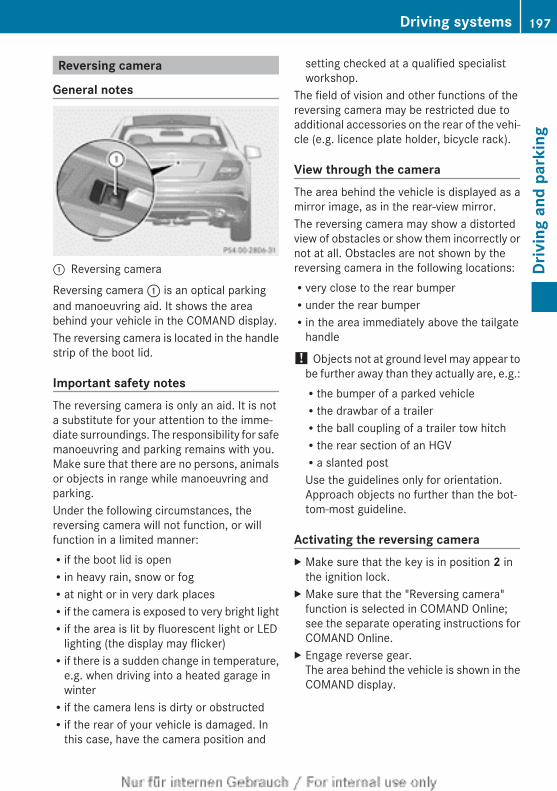
Reversing camera
General notes
: Reversing camera
Reversing camera : is an optical parkingand manoeuvring aid. It shows the areabehind your vehicle in the COMAND display.The reversing camera is located in the handlestrip of the boot lid.
Important safety notesThe reversing camera is only an aid. It is nota substitute for your attention to the imme-diate surroundings. The responsibility for safemanoeuvring and parking remains with you.Make sure that there are no persons, animalsor objects in range while manoeuvring andparking.Under the following circumstances, thereversing camera will not function, or willfunction in a limited manner:Rif the boot lid is openRin heavy rain, snow or fogRat night or in very dark placesRif the camera is exposed to very bright lightRif the area is lit by fluorescent light or LED
lighting (the display may flicker)Rif there is a sudden change in temperature,
e.g. when driving into a heated garage inwinterRif the camera lens is dirty or obstructedRif the rear of your vehicle is damaged. In
this case, have the camera position and
setting checked at a qualified specialistworkshop.
The field of vision and other functions of thereversing camera may be restricted due toadditional accessories on the rear of the vehi-cle (e.g. licence plate holder, bicycle rack).
View through the cameraThe area behind the vehicle is displayed as amirror image, as in the rear-view mirror.The reversing camera may show a distortedview of obstacles or show them incorrectly ornot at all. Obstacles are not shown by thereversing camera in the following locations:Rvery close to the rear bumperRunder the rear bumperRin the area immediately above the tailgate
handle
! Objects not at ground level may appear tobe further away than they actually are, e.g.:Rthe bumper of a parked vehicleRthe drawbar of a trailerRthe ball coupling of a trailer tow hitchRthe rear section of an HGVRa slanted postUse the guidelines only for orientation.Approach objects no further than the bot-tom-most guideline.
Activating the reversing cameraX Make sure that the key is in position 2 in
the ignition lock.X Make sure that the "Reversing camera"
function is selected in COMAND Online;see the separate operating instructions forCOMAND Online.
X Engage reverse gear.The area behind the vehicle is shown in theCOMAND display.
Driving systems 197
Driv
ing
and
park
ing
Z
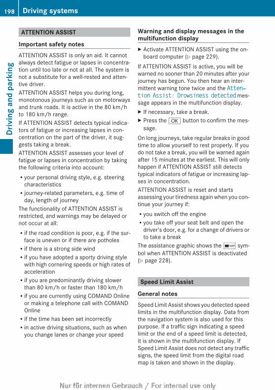
ATTENTION ASSIST
Important safety notesATTENTION ASSIST is only an aid. It cannotalways detect fatigue or lapses in concentra-tion until too late or not at all. The system isnot a substitute for a well-rested and atten-tive driver.ATTENTION ASSIST helps you during long,monotonous journeys such as on motorwaysand trunk roads. It is active in the 80 km/hto 180 km/h range.If ATTENTION ASSIST detects typical indica-tors of fatigue or increasing lapses in con-centration on the part of the driver, it sug-gests taking a break.ATTENTION ASSIST assesses your level offatigue or lapses in concentration by takingthe following criteria into account:Ryour personal driving style, e.g. steering
characteristicsRjourney-related parameters, e.g. time of
day, length of journeyThe functionality of ATTENTION ASSIST isrestricted, and warnings may be delayed ornot occur at all:Rif the road condition is poor, e.g. if the sur-
face is uneven or if there are potholesRif there is a strong side windRif you have adopted a sporty driving style
with high cornering speeds or high rates ofaccelerationRif you are predominantly driving slower
than 80 km/h or faster than 180 km/hRif you are currently using COMAND Online
or making a telephone call with COMANDOnlineRif the time has been set incorrectlyRin active driving situations, such as when
you change lanes or change your speed
Warning and display messages in themultifunction displayX Activate ATTENTION ASSIST using the on-
board computer (Y page 229).If ATTENTION ASSIST is active, you will bewarned no sooner than 20 minutes after yourjourney has begun. You then hear an inter-mittent warning tone twice and the Atten‐tion Assist: Drowsiness detected mes-sage appears in the multifunction display.X If necessary, take a break.X Press the a button to confirm the mes-
sage.On long journeys, take regular breaks in goodtime to allow yourself to rest properly. If youdo not take a break, you will be warned againafter 15 minutes at the earliest. This will onlyhappen if ATTENTION ASSIST still detectstypical indicators of fatigue or increasing lap-ses in concentration.ATTENTION ASSIST is reset and startsassessing your tiredness again when you con-tinue your journey if:Ryou switch off the engineRyou take off your seat belt and open the
driver's door, e.g. for a change of drivers orto take a break
The assistance graphic shows the é sym-bol when ATTENTION ASSIST is deactivated(Y page 228).
Speed Limit Assist
General notesSpeed Limit Assist shows you detected speedlimits in the multifunction display. Data fromthe navigation system is also used for thispurpose. If a traffic sign indicating a speedlimit or the end of a speed limit is detected,it is shown in the multifunction display. IfSpeed Limit Assist does not detect any trafficsigns, the speed limit from the digital roadmap is taken and shown in the display.
198 Driving systemsDr
ivin
g an
d pa
rkin
g
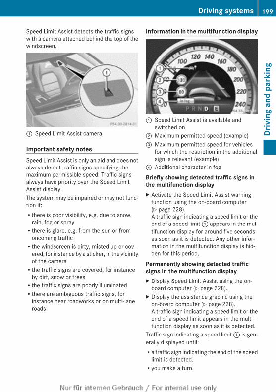
Speed Limit Assist detects the traffic signswith a camera attached behind the top of thewindscreen.
: Speed Limit Assist camera
Important safety notesSpeed Limit Assist is only an aid and does notalways detect traffic signs specifying themaximum permissible speed. Traffic signsalways have priority over the Speed LimitAssist display.The system may be impaired or may not func-tion if:Rthere is poor visibility, e.g. due to snow,
rain, fog or sprayRthere is glare, e.g. from the sun or from
oncoming trafficRthe windscreen is dirty, misted up or cov-
ered, for instance by a sticker, in the vicinityof the cameraRthe traffic signs are covered, for instance
by dirt, snow or treesRthe traffic signs are poorly illuminatedRthere are ambiguous traffic signs, for
instance near roadworks or on multi-laneroads
Information in the multifunction display
: Speed Limit Assist is available andswitched on
; Maximum permitted speed (example)= Maximum permitted speed for vehicles
for which the restriction in the additionalsign is relevant (example)
? Additional character in fog
Briefly showing detected traffic signs in the multifunction displayX Activate the Speed Limit Assist warning
function using the on-board computer(Y page 228).A traffic sign indicating a speed limit or theend of a speed limit : appears in the mul-tifunction display for around five secondsas soon as it is detected. Any other infor-mation in the multifunction display is hid-den for this period.
Permanently showing detected traffic signs in the multifunction displayX Display Speed Limit Assist using the on-
board computer (Y page 228).X Display the assistance graphic using the
on-board computer (Y page 228).A traffic sign indicating a speed limit or theend of a speed limit appears in the multi-function display as soon as it is detected.
Traffic sign indicating a speed limit : is gen-erally displayed until:Ra traffic sign indicating the end of the speed
limit is detected.Ryou make a turn.
Driving systems 199
Driv
ing
and
park
ing
Z
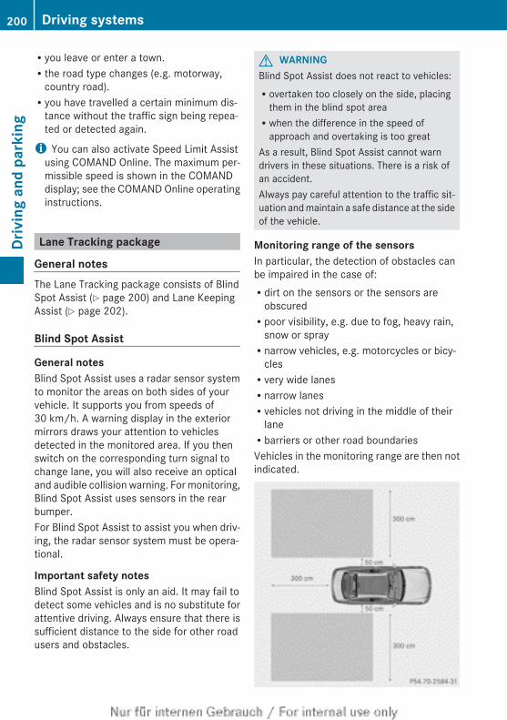
Ryou leave or enter a town.Rthe road type changes (e.g. motorway,
country road).Ryou have travelled a certain minimum dis-
tance without the traffic sign being repea-ted or detected again.
i You can also activate Speed Limit Assistusing COMAND Online. The maximum per-missible speed is shown in the COMANDdisplay; see the COMAND Online operatinginstructions.
Lane Tracking package
General notesThe Lane Tracking package consists of BlindSpot Assist (Y page 200) and Lane KeepingAssist (Y page 202).
Blind Spot Assist
General notesBlind Spot Assist uses a radar sensor systemto monitor the areas on both sides of yourvehicle. It supports you from speeds of30 km/h. A warning display in the exteriormirrors draws your attention to vehiclesdetected in the monitored area. If you thenswitch on the corresponding turn signal tochange lane, you will also receive an opticaland audible collision warning. For monitoring,Blind Spot Assist uses sensors in the rearbumper.For Blind Spot Assist to assist you when driv-ing, the radar sensor system must be opera-tional.
Important safety notesBlind Spot Assist is only an aid. It may fail todetect some vehicles and is no substitute forattentive driving. Always ensure that there issufficient distance to the side for other roadusers and obstacles.
G WARNINGBlind Spot Assist does not react to vehicles:Rovertaken too closely on the side, placing
them in the blind spot areaRwhen the difference in the speed of
approach and overtaking is too greatAs a result, Blind Spot Assist cannot warndrivers in these situations. There is a risk ofan accident.Always pay careful attention to the traffic sit-uation and maintain a safe distance at the sideof the vehicle.
Monitoring range of the sensorsIn particular, the detection of obstacles canbe impaired in the case of:Rdirt on the sensors or the sensors are
obscuredRpoor visibility, e.g. due to fog, heavy rain,
snow or sprayRnarrow vehicles, e.g. motorcycles or bicy-
clesRvery wide lanesRnarrow lanesRvehicles not driving in the middle of their
laneRbarriers or other road boundariesVehicles in the monitoring range are then notindicated.
200 Driving systemsDr
ivin
g an
d pa
rkin
g
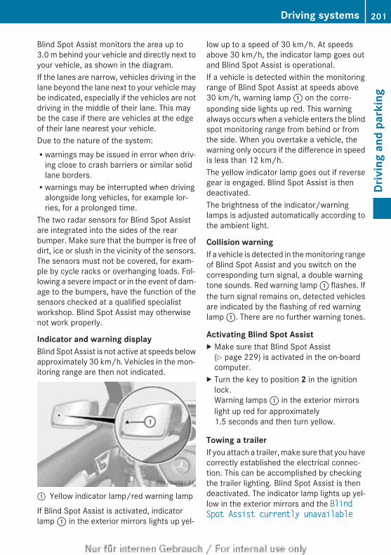
Blind Spot Assist monitors the area up to3.0 m behind your vehicle and directly next toyour vehicle, as shown in the diagram.If the lanes are narrow, vehicles driving in thelane beyond the lane next to your vehicle maybe indicated, especially if the vehicles are notdriving in the middle of their lane. This maybe the case if there are vehicles at the edgeof their lane nearest your vehicle.Due to the nature of the system:Rwarnings may be issued in error when driv-
ing close to crash barriers or similar solidlane borders.Rwarnings may be interrupted when driving
alongside long vehicles, for example lor-ries, for a prolonged time.
The two radar sensors for Blind Spot Assistare integrated into the sides of the rearbumper. Make sure that the bumper is free ofdirt, ice or slush in the vicinity of the sensors.The sensors must not be covered, for exam-ple by cycle racks or overhanging loads. Fol-lowing a severe impact or in the event of dam-age to the bumpers, have the function of thesensors checked at a qualified specialistworkshop. Blind Spot Assist may otherwisenot work properly.
Indicator and warning displayBlind Spot Assist is not active at speeds belowapproximately 30 km/h. Vehicles in the mon-itoring range are then not indicated.
: Yellow indicator lamp/red warning lamp
If Blind Spot Assist is activated, indicatorlamp : in the exterior mirrors lights up yel-
low up to a speed of 30 km/h. At speedsabove 30 km/h, the indicator lamp goes outand Blind Spot Assist is operational.If a vehicle is detected within the monitoringrange of Blind Spot Assist at speeds above30 km/h, warning lamp : on the corre-sponding side lights up red. This warningalways occurs when a vehicle enters the blindspot monitoring range from behind or fromthe side. When you overtake a vehicle, thewarning only occurs if the difference in speedis less than 12 km/h.The yellow indicator lamp goes out if reversegear is engaged. Blind Spot Assist is thendeactivated.The brightness of the indicator/warninglamps is adjusted automatically according tothe ambient light.
Collision warningIf a vehicle is detected in the monitoring rangeof Blind Spot Assist and you switch on thecorresponding turn signal, a double warningtone sounds. Red warning lamp : flashes. Ifthe turn signal remains on, detected vehiclesare indicated by the flashing of red warninglamp :. There are no further warning tones.
Activating Blind Spot AssistX Make sure that Blind Spot Assist
(Y page 229) is activated in the on-boardcomputer.
X Turn the key to position 2 in the ignitionlock.Warning lamps : in the exterior mirrorslight up red for approximately1.5 seconds and then turn yellow.
Towing a trailerIf you attach a trailer, make sure that you havecorrectly established the electrical connec-tion. This can be accomplished by checkingthe trailer lighting. Blind Spot Assist is thendeactivated. The indicator lamp lights up yel-low in the exterior mirrors and the Blind Spot Assist currently unavailable
Driving systems 201
Driv
ing
and
park
ing
Z
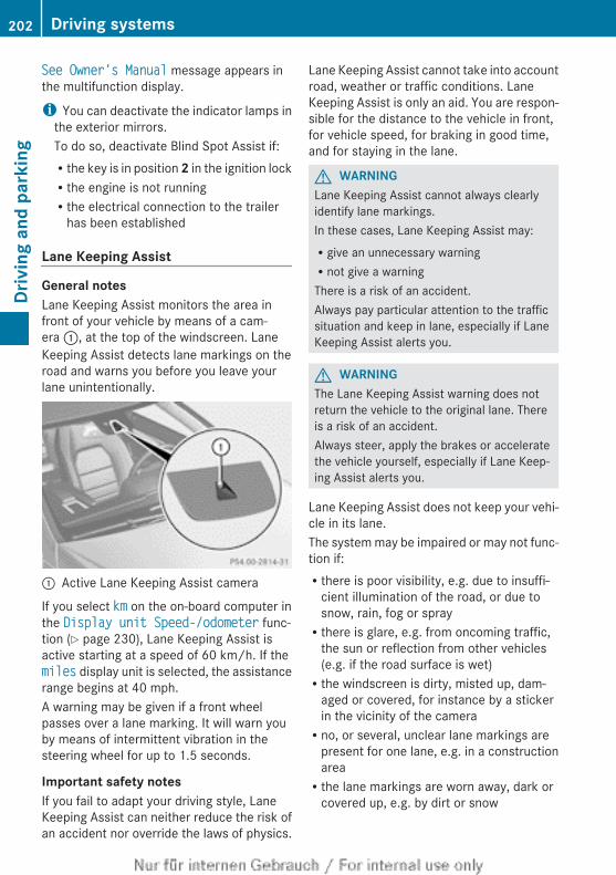
See Owner's Manual message appears inthe multifunction display.
i You can deactivate the indicator lamps inthe exterior mirrors.To do so, deactivate Blind Spot Assist if:Rthe key is in position 2 in the ignition lockRthe engine is not runningRthe electrical connection to the trailer
has been established
Lane Keeping Assist
General notesLane Keeping Assist monitors the area infront of your vehicle by means of a cam-era :, at the top of the windscreen. LaneKeeping Assist detects lane markings on theroad and warns you before you leave yourlane unintentionally.
: Active Lane Keeping Assist camera
If you select km on the on-board computer inthe Display unit Speed-/odometer func-tion (Y page 230), Lane Keeping Assist isactive starting at a speed of 60 km/h. If themiles display unit is selected, the assistancerange begins at 40 mph.A warning may be given if a front wheelpasses over a lane marking. It will warn youby means of intermittent vibration in thesteering wheel for up to 1.5 seconds.
Important safety notesIf you fail to adapt your driving style, LaneKeeping Assist can neither reduce the risk ofan accident nor override the laws of physics.
Lane Keeping Assist cannot take into accountroad, weather or traffic conditions. LaneKeeping Assist is only an aid. You are respon-sible for the distance to the vehicle in front,for vehicle speed, for braking in good time,and for staying in the lane.
G WARNINGLane Keeping Assist cannot always clearlyidentify lane markings.In these cases, Lane Keeping Assist may:Rgive an unnecessary warningRnot give a warningThere is a risk of an accident.Always pay particular attention to the trafficsituation and keep in lane, especially if LaneKeeping Assist alerts you.
G WARNINGThe Lane Keeping Assist warning does notreturn the vehicle to the original lane. Thereis a risk of an accident.Always steer, apply the brakes or acceleratethe vehicle yourself, especially if Lane Keep-ing Assist alerts you.
Lane Keeping Assist does not keep your vehi-cle in its lane.The system may be impaired or may not func-tion if:Rthere is poor visibility, e.g. due to insuffi-
cient illumination of the road, or due tosnow, rain, fog or sprayRthere is glare, e.g. from oncoming traffic,
the sun or reflection from other vehicles(e.g. if the road surface is wet)Rthe windscreen is dirty, misted up, dam-
aged or covered, for instance by a stickerin the vicinity of the cameraRno, or several, unclear lane markings are
present for one lane, e.g. in a constructionareaRthe lane markings are worn away, dark or
covered up, e.g. by dirt or snow
202 Driving systemsDr
ivin
g an
d pa
rkin
g
Rthe distance to the vehicle in front is toosmall and the lane markings thus cannot bedetectedRthe lane markings change quickly, e.g.
lanes branch off, cross one another ormergeRthe road is narrow and windingRthere are highly variable shade conditions
on the road
Activating Lane Keeping AssistX Activate Lane Keeping Assist using the on-
board computer; to do so, select Stand‐ard or Adaptive(Y page 230).If you drive at speeds above 60 km/h andlane markings are detected, the lines in theassistance graphic display (Y page 228)are shown in green. Lane Keeping Assist isready for use.
StandardIf Standard is selected, no warning vibrationoccurs if:Ryou have switched on the turn signals. In
this case, the warnings are suppressed fora certain period of time.Ra driving safety system intervenes, such as
ABS, BAS or ESP®.
AdaptiveWhen Adaptive is selected, no warning vibra-tion occurs if:Ryou have switched on the turn signals. In
this case, the warnings are suppressed fora certain period of time.Ra driving safety system intervenes, such as
ABS, BAS or ESP®.Ryou accelerate hard, e.g. kickdown.Ryou brake hard.Ryou steer actively, e.g. swerve to avoid an
obstacle or change lane quickly.Ryou cut the corner on a sharp bend.In order that you are warned only when nec-essary and in good time if you cross the lanemarking, the system recognises certain con-ditions and warns you accordingly.
The warning vibration occurs earlier if:Ryou approach the outer lane marking on a
bend.Rthe road has very wide lanes, e.g. a motor-
way.Rthe system recognises solid lane markings.The warning vibration occurs later if:Rthe road has narrow lanes.Ryou cut the corner on a bend.
Towing a trailerIf you attach a trailer, make sure that you havecorrectly established the electrical connec-tion. This can be accomplished by checkingthe trailer lighting.
Active Driving Assistance package
General notesThe Active Driving Assistance package con-sists of DISTRONIC PLUS (Y page 179), ActiveBlind Spot Assist (Y page 203) and ActiveLane Keeping Assist (Y page 206).
Active Blind Spot Assist
General notesActive Blind Spot Assist uses a radar sensorsystem to monitor the area to the sides ofyour vehicle which are behind the driver. Awarning display in the exterior mirrors drawsyour attention to vehicles detected in themonitored area. If you then switch on the cor-responding turn signal to change lanes, youwill also receive an optical and audible colli-sion warning. If a risk of side impact is detec-ted, corrective braking may help you avoid acollision. To support the course-correctingbrake application, Active Blind Spot Assistalso uses the forward-facing radar sensor sys-tem. The space available in the direction oftravel as well as to the side of the vehicle isevaluated before a course-correcting brakingapplication is performed.
Driving systems 203
Driv
ing
and
park
ing
Z
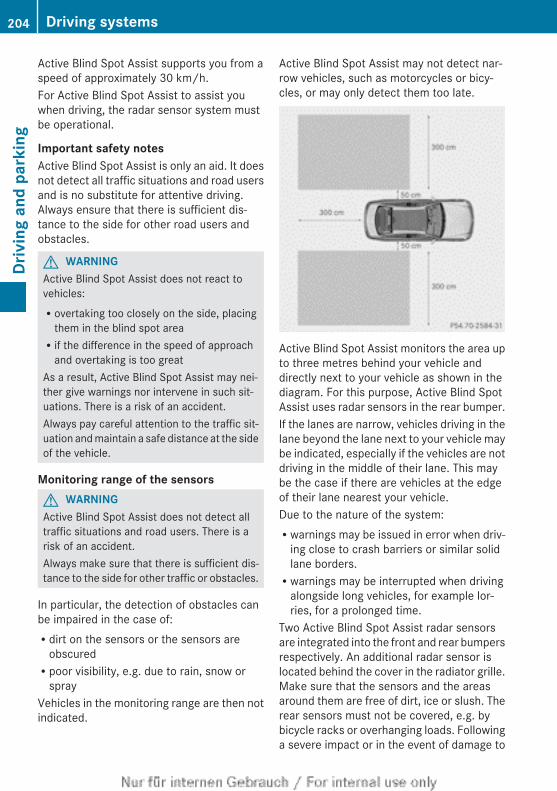
Active Blind Spot Assist supports you from aspeed of approximately 30 km/h.For Active Blind Spot Assist to assist youwhen driving, the radar sensor system mustbe operational.
Important safety notesActive Blind Spot Assist is only an aid. It doesnot detect all traffic situations and road usersand is no substitute for attentive driving.Always ensure that there is sufficient dis-tance to the side for other road users andobstacles.
G WARNINGActive Blind Spot Assist does not react tovehicles:Rovertaking too closely on the side, placing
them in the blind spot areaRif the difference in the speed of approach
and overtaking is too greatAs a result, Active Blind Spot Assist may nei-ther give warnings nor intervene in such sit-uations. There is a risk of an accident.Always pay careful attention to the traffic sit-uation and maintain a safe distance at the sideof the vehicle.
Monitoring range of the sensorsG WARNINGActive Blind Spot Assist does not detect alltraffic situations and road users. There is arisk of an accident.Always make sure that there is sufficient dis-tance to the side for other traffic or obstacles.
In particular, the detection of obstacles canbe impaired in the case of:Rdirt on the sensors or the sensors are
obscuredRpoor visibility, e.g. due to rain, snow or
sprayVehicles in the monitoring range are then notindicated.
Active Blind Spot Assist may not detect nar-row vehicles, such as motorcycles or bicy-cles, or may only detect them too late.
Active Blind Spot Assist monitors the area upto three metres behind your vehicle anddirectly next to your vehicle as shown in thediagram. For this purpose, Active Blind SpotAssist uses radar sensors in the rear bumper.If the lanes are narrow, vehicles driving in thelane beyond the lane next to your vehicle maybe indicated, especially if the vehicles are notdriving in the middle of their lane. This maybe the case if there are vehicles at the edgeof their lane nearest your vehicle.Due to the nature of the system:Rwarnings may be issued in error when driv-
ing close to crash barriers or similar solidlane borders.Rwarnings may be interrupted when driving
alongside long vehicles, for example lor-ries, for a prolonged time.
Two Active Blind Spot Assist radar sensorsare integrated into the front and rear bumpersrespectively. An additional radar sensor islocated behind the cover in the radiator grille.Make sure that the sensors and the areasaround them are free of dirt, ice or slush. Therear sensors must not be covered, e.g. bybicycle racks or overhanging loads. Followinga severe impact or in the event of damage to
204 Driving systemsDr
ivin
g an
d pa
rkin
g
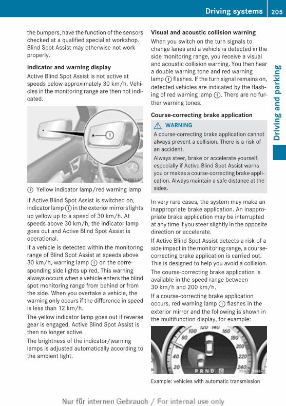
the bumpers, have the function of the sensorschecked at a qualified specialist workshop.Blind Spot Assist may otherwise not workproperly.
Indicator and warning displayActive Blind Spot Assist is not active atspeeds below approximately 30 km/h. Vehi-cles in the monitoring range are then not indi-cated.
: Yellow indicator lamp/red warning lamp
If Active Blind Spot Assist is switched on,indicator lamp : in the exterior mirrors lightsup yellow up to a speed of 30 km/h. Atspeeds above 30 km/h, the indicator lampgoes out and Active Blind Spot Assist isoperational.If a vehicle is detected within the monitoringrange of Blind Spot Assist at speeds above30 km/h, warning lamp : on the corre-sponding side lights up red. This warningalways occurs when a vehicle enters the blindspot monitoring range from behind or fromthe side. When you overtake a vehicle, thewarning only occurs if the difference in speedis less than 12 km/h.The yellow indicator lamp goes out if reversegear is engaged. Active Blind Spot Assist isthen no longer active.The brightness of the indicator/warninglamps is adjusted automatically according tothe ambient light.
Visual and acoustic collision warningWhen you switch on the turn signals tochange lanes and a vehicle is detected in theside monitoring range, you receive a visualand acoustic collision warning. You then heara double warning tone and red warninglamp : flashes. If the turn signal remains on,detected vehicles are indicated by the flash-ing of red warning lamp :. There are no fur-ther warning tones.
Course-correcting brake applicationG WARNINGA course-correcting brake application cannotalways prevent a collision. There is a risk ofan accident.Always steer, brake or accelerate yourself,especially if Active Blind Spot Assist warnsyou or makes a course-correcting brake appli-cation. Always maintain a safe distance at thesides.
In very rare cases, the system may make aninappropriate brake application. An inappro-priate brake application may be interruptedat any time if you steer slightly in the oppositedirection or accelerate.If Active Blind Spot Assist detects a risk of aside impact in the monitoring range, a course-correcting brake application is carried out.This is designed to help you avoid a collision.The course-correcting brake application isavailable in the speed range between30 km/h and 200 km/h.If a course-correcting brake applicationoccurs, red warning lamp : flashes in theexterior mirror and the following is shown inthe multifunction display, for example:
Example: vehicles with automatic transmission
Driving systems 205
Driv
ing
and
park
ing
Z
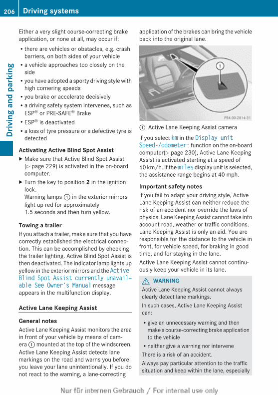
Either a very slight course-correcting brakeapplication, or none at all, may occur if:Rthere are vehicles or obstacles, e.g. crash
barriers, on both sides of your vehicleRa vehicle approaches too closely on the
sideRyou have adopted a sporty driving style with
high cornering speedsRyou brake or accelerate decisivelyRa driving safety system intervenes, such as
ESP® or PRE-SAFE® BrakeRESP® is deactivatedRa loss of tyre pressure or a defective tyre is
detected
Activating Active Blind Spot AssistX Make sure that Active Blind Spot Assist
(Y page 229) is activated in the on-boardcomputer.
X Turn the key to position 2 in the ignitionlock.Warning lamps : in the exterior mirrorslight up red for approximately1.5 seconds and then turn yellow.
Towing a trailerIf you attach a trailer, make sure that you havecorrectly established the electrical connec-tion. This can be accomplished by checkingthe trailer lighting. Active Blind Spot Assist isthen deactivated. The indicator lamp lights upyellow in the exterior mirrors and the Active Blind Spot Assist currently unavail‐able See Owner's Manual messageappears in the multifunction display.
Active Lane Keeping Assist
General notesActive Lane Keeping Assist monitors the areain front of your vehicle by means of cam-era : mounted at the top of the windscreen.Active Lane Keeping Assist detects lanemarkings on the road and warns you beforeyou leave your lane unintentionally. If you donot react to the warning, a lane-correcting
application of the brakes can bring the vehicleback into the original lane.
: Active Lane Keeping Assist camera
If you select km in the Display unit Speed-/odometer: function on the on-boardcomputer(Y page 230), Active Lane KeepingAssist is activated starting at a speed of60 km/h. If the miles display unit is selected,the assistance range begins at 40 mph.
Important safety notesIf you fail to adapt your driving style, ActiveLane Keeping Assist can neither reduce therisk of an accident nor override the laws ofphysics. Lane Keeping Assist cannot take intoaccount road, weather or traffic conditions.Lane Keeping Assist is only an aid. You areresponsible for the distance to the vehicle infront, for vehicle speed, for braking in goodtime, and for staying in the lane.Active Lane Keeping Assist cannot continu-ously keep your vehicle in its lane.
G WARNINGActive Lane Keeping Assist cannot alwaysclearly detect lane markings.In such cases, Active Lane Keeping Assistcan:Rgive an unnecessary warning and then
make a course-correcting brake applicationto the vehicleRneither give a warning nor interveneThere is a risk of an accident.Always pay particular attention to the trafficsituation and keep within the lane, especially
206 Driving systemsDr
ivin
g an
d pa
rkin
g
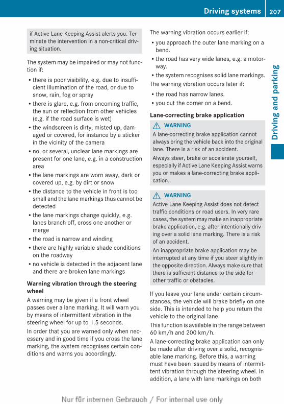
if Active Lane Keeping Assist alerts you. Ter-minate the intervention in a non-critical driv-ing situation.
The system may be impaired or may not func-tion if:Rthere is poor visibility, e.g. due to insuffi-
cient illumination of the road, or due tosnow, rain, fog or sprayRthere is glare, e.g. from oncoming traffic,
the sun or reflection from other vehicles(e.g. if the road surface is wet)Rthe windscreen is dirty, misted up, dam-
aged or covered, for instance by a stickerin the vicinity of the cameraRno, or several, unclear lane markings are
present for one lane, e.g. in a constructionareaRthe lane markings are worn away, dark or
covered up, e.g. by dirt or snowRthe distance to the vehicle in front is too
small and the lane markings thus cannot bedetectedRthe lane markings change quickly, e.g.
lanes branch off, cross one another ormergeRthe road is narrow and windingRthere are highly variable shade conditions
on the roadwayRno vehicle is detected in the adjacent lane
and there are broken lane markings
Warning vibration through the steeringwheelA warning may be given if a front wheelpasses over a lane marking. It will warn youby means of intermittent vibration in thesteering wheel for up to 1.5 seconds.In order that you are warned only when nec-essary and in good time if you cross the lanemarking, the system recognises certain con-ditions and warns you accordingly.
The warning vibration occurs earlier if:Ryou approach the outer lane marking on a
bend.Rthe road has very wide lanes, e.g. a motor-
way.Rthe system recognises solid lane markings.The warning vibration occurs later if:Rthe road has narrow lanes.Ryou cut the corner on a bend.
Lane-correcting brake applicationG WARNINGA lane-correcting brake application cannotalways bring the vehicle back into the originallane. There is a risk of an accident.Always steer, brake or accelerate yourself,especially if Active Lane Keeping Assist warnsyou or makes a lane-correcting brake appli-cation.
G WARNINGActive Lane Keeping Assist does not detecttraffic conditions or road users. In very rarecases, the system may make an inappropriatebrake application, e.g. after intentionally driv-ing over a solid lane marking. There is a riskof an accident.An inappropriate brake application may beinterrupted at any time if you steer slightly inthe opposite direction. Always make sure thatthere is sufficient distance to the side forother traffic or obstacles.
If you leave your lane under certain circum-stances, the vehicle will brake briefly on oneside. This is intended to help you return thevehicle to the original lane.This function is available in the range between60 km/h and 200 km/h.A lane-correcting brake application can onlybe made after driving over a solid, recognis-able lane marking. Before this, a warningmust have been issued by means of intermit-tent vibration through the steering wheel. Inaddition, a lane with lane markings on both
Driving systems 207
Driv
ing
and
park
ing
Z
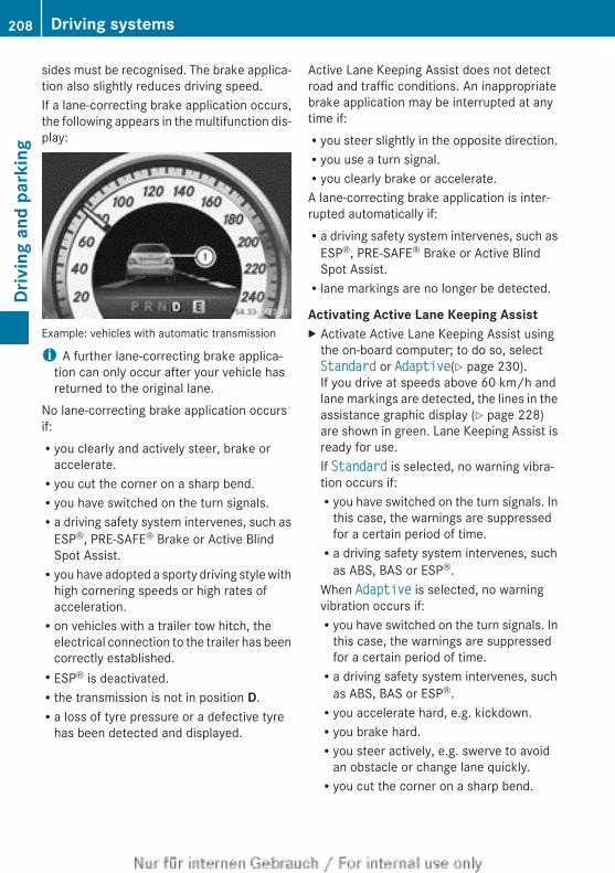
sides must be recognised. The brake applica-tion also slightly reduces driving speed.If a lane-correcting brake application occurs,the following appears in the multifunction dis-play:
Example: vehicles with automatic transmission
i A further lane-correcting brake applica-tion can only occur after your vehicle hasreturned to the original lane.
No lane-correcting brake application occursif:Ryou clearly and actively steer, brake or
accelerate.Ryou cut the corner on a sharp bend.Ryou have switched on the turn signals.Ra driving safety system intervenes, such as
ESP®, PRE-SAFE® Brake or Active BlindSpot Assist.Ryou have adopted a sporty driving style with
high cornering speeds or high rates ofacceleration.Ron vehicles with a trailer tow hitch, the
electrical connection to the trailer has beencorrectly established.RESP® is deactivated.Rthe transmission is not in position D.Ra loss of tyre pressure or a defective tyre
has been detected and displayed.
Active Lane Keeping Assist does not detectroad and traffic conditions. An inappropriatebrake application may be interrupted at anytime if:Ryou steer slightly in the opposite direction.Ryou use a turn signal.Ryou clearly brake or accelerate.A lane-correcting brake application is inter-rupted automatically if:Ra driving safety system intervenes, such as
ESP®, PRE-SAFE® Brake or Active BlindSpot Assist.Rlane markings are no longer be detected.
Activating Active Lane Keeping AssistX Activate Active Lane Keeping Assist using
the on-board computer; to do so, selectStandard or Adaptive(Y page 230).If you drive at speeds above 60 km/h andlane markings are detected, the lines in theassistance graphic display (Y page 228)are shown in green. Lane Keeping Assist isready for use.If Standard is selected, no warning vibra-tion occurs if:Ryou have switched on the turn signals. In
this case, the warnings are suppressedfor a certain period of time.Ra driving safety system intervenes, such
as ABS, BAS or ESP®.When Adaptive is selected, no warningvibration occurs if:Ryou have switched on the turn signals. In
this case, the warnings are suppressedfor a certain period of time.Ra driving safety system intervenes, such
as ABS, BAS or ESP®.Ryou accelerate hard, e.g. kickdown.Ryou brake hard.Ryou steer actively, e.g. swerve to avoid
an obstacle or change lane quickly.Ryou cut the corner on a sharp bend.
208 Driving systemsDr
ivin
g an
d pa
rkin
g
Towing a trailerIf you attach a trailer, make sure that you havecorrectly established the electrical connec-tion. This can be accomplished by checkingthe trailer lighting.
Towing a trailer
Notes on towing a trailer
Important safety notes
G WARNINGThe braking system can overheat if you leaveyour foot on the brake pedal while driving.This increases the braking distance and couldeven cause the braking system to fail. Thereis a risk of an accident.Never use the brake pedal as a footrest. Donot simultaneously depress both the brakepedal and the accelerator pedal while driving.
G WARNINGYou could lose control of the vehicle/trailercombination if it begins to swerve. The vehi-cle/trailer combination could even overturn.There is a risk of an accident.On no account should you attempt tostraighten out the vehicle/trailer combina-tion by increasing speed. Decrease yourspeed and do not countersteer. Brake if nec-essary.
G WARNINGIf the maximum the permissible load for a car-rier system is exceeded, the carrier couldcome loose from the vehicle and endangerother road users. There is a risk of an accidentand injury.Never exceed the permissible noseweightwhen using a carrier.
! Depressing the brake pedal constantlyresults in excessive and premature wear tothe brake pads.
If you exceed the maximum permissible nose-weight of the trailer drawbar on the ball cou-pling, the following may become damaged:Ryour vehicleRthe trailerRthe ball couplingRthe trailer tow hitchThe vehicle/trailer combination couldbecome unstable.If the noseweight used is lower than the min-imum permissible noseweight, the vehicle/trailer combination could also become unsta-ble.To avoid hazardous situations:Rmake sure to check the noseweight before
each journey.Ruse a drawbar noseweight as close as pos-
sible to the maximum noseweight.Rdo not exceed the maximum permissible
noseweight.Rdo not use a noseweight lower than the
minimum permissible trailer drawbar nose-weight.
When reversing the vehicle towards thetrailer, make sure there is nobody betweenthe trailer and the vehicle.Couple and uncouple the trailer carefully. Ifyou do not couple the trailer to the towingvehicle correctly, the trailer could becomedetached.Make sure that the following values are notexceeded:Rthe permissible trailer drawbar noseweightRthe permissible trailer loadRthe permissible rear axle load of the towing
vehicleRthe maximum permissible gross vehicle
weight of both the towing vehicle and thetrailer
Towing a trailer 209
Driv
ing
and
park
ing
Z
The applicable permissible values, whichmust not be exceeded, can be found:Rin the vehicle documentsRon the identification plates of the trailer tow
hitch, the trailer and the vehicleIf the values differ, the lowest value applies.You will find the values approved by the man-ufacturer on the vehicle identification platesand those for the towing vehicle under "Tech-nical data" (Y page 382).When towing a trailer, your vehicle's handlingcharacteristics will be different in comparisonto when driving without a trailer.The vehicle/trailer combination:Ris heavierRis restricted in its acceleration and gradi-
ent-climbing capabilityRhas an increased braking distanceRis affected more by strong crosswindsRdemands more sensitive steeringRhas a larger turning circleThis can impair the vehicle's handling char-acteristics. Adapt your style of driving accord-ingly. Maintain a safe distance. Drive care-fully.When towing a trailer, always adjust yourspeed to the current road and weather con-ditions. Do not exceed the maximum permis-sible speed for your vehicle/trailer combina-tion.
General notesi When towing a trailer, set the tyre pres-
sure on the rear axle of the towing vehiclefor a maximum load; see the tyre pressuretable in the fuel filler flap (Y page 350).
Please note that when towing a trailer, PARK-TRONIC (Y page 191), Parking Guidance(Y page 194) and Blind Spot Assist(Y page 200) are only available with limita-tions, or not at all.
i The height of the ball coupling changeswith the load of the vehicle. If necessary,
use a trailer with a height-adjustable draw-bar.
You will find fitting dimensions and loadsunder "Technical data" (Y page 381).
Driving tipsi Observe the notes on ESP® trailer stabi-
lisation (Y page 76).The maximum permissible speed for vehicle/trailer combinations depends on the type oftrailer. Before beginning the journey, checkthe trailer's documents to see what the max-imum permitted speed is. Observe the legallyprescribed maximum speed in the relevantcountry.For certain Mercedes-Benz vehicles, the max-imum permissible rear axle load is increasedwhen towing a trailer. Refer to the "Technicaldata" section to find out whether this appliesto your vehicle.If you utilise any of the added maximum rearaxle load when towing a trailer, the vehicle/trailer combination may not exceed a maxi-mum speed of 100 km/h for reasons con-cerning the operating permit. This alsoapplies in countries in which the permissiblemaximum speed for vehicle/trailer combina-tions is above 100 km/h.When towing a trailer, your vehicle's handlingcharacteristics will be different in comparisonto when driving without a trailer and it willconsume more fuel.Change into a lower gear in good time on longand steep downhill gradients. On vehicleswith automatic transmission, you must selectshift range 1, 2 or 3.
i This also applies if you have activatedcruise control, SPEEDTRONIC or DIS-TRONIC PLUS.
This will use the braking effect of the engine,so less braking will be required to maintainvehicle speed. This relieves the load on thebrake system and prevents the brakes fromoverheating and wearing too quickly. If you
210 Towing a trailerDr
ivin
g an
d pa
rkin
g
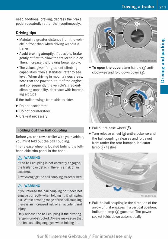
need additional braking, depress the brakepedal repeatedly rather than continuously.
Driving tipsRMaintain a greater distance from the vehi-
cle in front than when driving without atrailer.RAvoid braking abruptly. If possible, brake
gently at first to allow the trailer to run on.Then, increase the braking force rapidly.RThe values given for gradient-climbing
capabilities from a standstill refer to sealevel. When driving in mountainous areas,note that the power output of the engine,and consequently the vehicle's gradient-climbing capability, decrease with increas-ing altitude.
If the trailer swings from side to side:X Do not accelerate.X Do not countersteer.X Brake if necessary.
Folding out the ball couplingBefore you can tow a trailer with your vehicle,you must fold out the ball coupling.The release wheel is located behind the left-hand side trim panel in the boot.
G WARNINGIf the ball coupling is not correctly engaged,the trailer can detach. There is a risk of anaccident.Always engage the ball coupling as described.
G WARNINGIf you release the ball coupling or it does notengage correctly when folding in, it will swingout. Within pivoting range of the ball coupling,there is an increased risk of an accident andinjury.Only release the ball coupling if the pivotingrange is unobstructed. Always make sure thatthe ball coupling engages when folding in.
X To open the cover: turn handle : anti-clockwise and fold down cover ;.
X Pull out release wheel =.X Turn release wheel = anti-clockwise until
the ball coupling releases and folds outfrom under the rear bumper. Indicatorlamp ? flashes.
X Pull the ball coupling in the direction of thearrow until it engages in a vertical position.Indicator lamp ? goes out. The powersocket folds down automatically.
Towing a trailer 211
Driv
ing
and
park
ing
Z
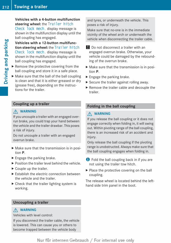
Vehicles with a 4-button multifunction steering wheel: the Trailer hitch Check lock mech. display message isshown in the multifunction display until theball coupling has engaged.Vehicles with a 12-button multifunc-tion steering wheel: the Trailer hitch Check lock mech. display message isshown in the multifunction display until theball coupling has engaged.
X Remove the protective covering from theball coupling and store it in a safe place.
X Make sure that the ball of the ball couplingis clean and that it is either greased or dry(grease free), depending on the instruc-tions for the trailer.
Coupling up a trailer
G WARNINGIf you uncouple a trailer with an engaged over-run brake, you could trap your hand betweenthe vehicle and the trailer drawbar. This posesa risk of injury.Do not uncouple a trailer with an engagedoverrun brake.
X Make sure that the transmission is in posi-tion P.
X Engage the parking brake.X Position the trailer level behind the vehicle.X Couple up the trailer.X Establish the electric connection between
the vehicle and the trailer.X Check that the trailer lighting system is
working.
Uncoupling a trailer
G WARNINGVehicles with level control:If you disconnect the trailer cable, the vehicleis lowered. This can cause you or others tobecome trapped between the vehicle body
and tyres, or underneath the vehicle. Thisposes a risk of injury.Make sure that no-one is in the immediatevicinity of the wheel arch or underneath thevehicle when disconnecting the trailer cable.
! Do not disconnect a trailer with anengaged overrun brake. Otherwise, yourvehicle could be damaged by the rebound-ing of the overrun brake.
X Make sure that the transmission is in posi-tion P.
X Engage the parking brake.X Secure the trailer against rolling away.X Remove the trailer cable and decouple the
trailer.
Folding in the ball coupling
G WARNINGIf you release the ball coupling or it does notengage correctly when folding in, it will swingout. Within pivoting range of the ball coupling,there is an increased risk of an accident andinjury.Only release the ball coupling if the pivotingrange is unobstructed. Always make sure thatthe ball coupling engages when folding in.
i Fold the ball coupling back in if you arenot using the trailer tow hitch.
X Place the protective covering on the ballcoupling.
The release wheel is located behind the left-hand side trim panel in the boot.
212 Towing a trailerDr
ivin
g an
d pa
rkin
g
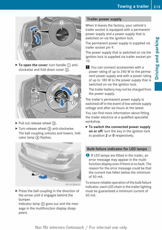
X To open the cover: turn handle : anti-clockwise and fold down cover ;.
X Pull out release wheel =.X Turn release wheel = anti-clockwise.
The ball coupling unlocks and lowers. Indi-cator lamp ? flashes.
X Press the ball coupling in the direction ofthe arrow until it engages behind thebumper.Indicator lamp ? goes out and the mes-sage in the multifunction display disap-pears.
Trailer power supplyWhen it leaves the factory, your vehicle'strailer socket is equipped with a permanentpower supply and a power supply that isswitched on via the ignition lock.The permanent power supply is supplied viatrailer socket pin 9.The power supply that is switched on via theignition lock is supplied via trailer socket pin10.
! You can connect accessories with apower rating of up to 240 W to the perma-nent power supply and with a power ratingof up to 180 W to the power supply that isswitched on via the ignition lock.The trailer battery may not be charged fromthe power supply.
The trailer's permanent power supply isswitched off in the event of low vehicle supplyvoltage and after six hours at the latest.You can find more information about fittingthe trailer electrics at a qualified specialistworkshop.X To switch the connected power supply
on or off: turn the key in the ignition lockto position 2 or 0 respectively.
Bulb failure indicator for LED lampsi If LED lamps are fitted in the trailer, an
error message may appear in the multi-function display even if there is no fault. Thereason for the error message could be thatthe current has fallen below the minimumof 50 mA.
To ensure reliable operation of the bulb failureindicator, each LED chain in the trailer lightingmust be guaranteed a minimum current of50 mA.
Towing a trailer 213
Driv
ing
and
park
ing
Z
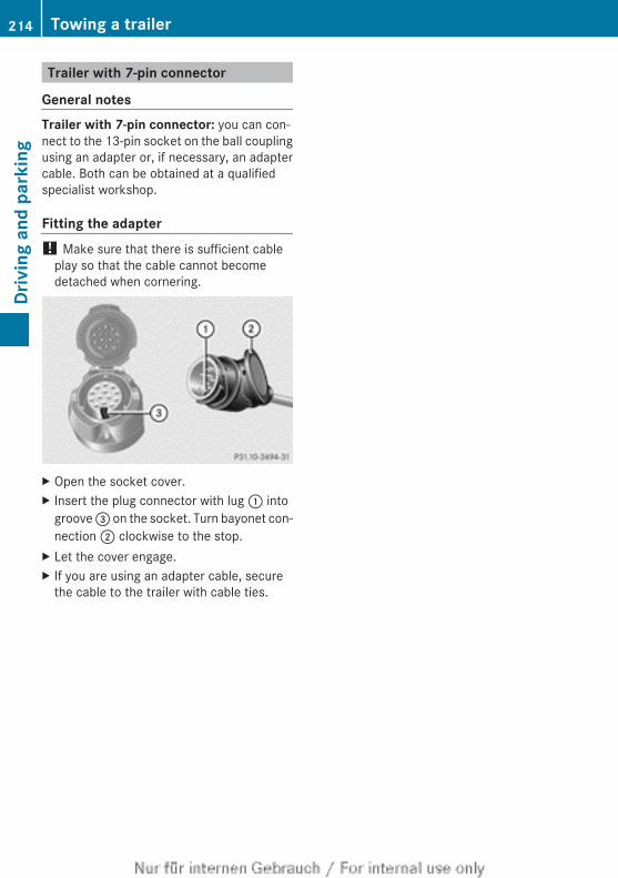
Trailer with 7-pin connector
General notesTrailer with 7-pin connector: you can con-nect to the 13-pin socket on the ball couplingusing an adapter or, if necessary, an adaptercable. Both can be obtained at a qualifiedspecialist workshop.
Fitting the adapter! Make sure that there is sufficient cable
play so that the cable cannot becomedetached when cornering.
X Open the socket cover.X Insert the plug connector with lug : into
groove = on the socket. Turn bayonet con-nection ; clockwise to the stop.
X Let the cover engage.X If you are using an adapter cable, secure
the cable to the trailer with cable ties.
214 Towing a trailerDr
ivin
g an
d pa
rkin
g
Useful information ............................ 216Important safety notes .................... 216Displays and operation (4-buttonmultifunction steering wheel) ......... 216Displays and operation (12-buttonmultifunction steering wheel) ......... 219Display messages ............................. 240Warning and indicator lamps in theinstrument cluster ............................ 281
215
On-b
oard
com
pute
r and
dis
play
s
Useful information
i This Owner's Manual describes all mod-els, series and optional equipment for yourvehicle that were available at the time ofgoing to press. National variations are pos-sible. Note that your vehicle may not beequipped with all of the functions descri-bed. This is also the case for systems andfunctions relevant to safety.
i Read the information on qualified special-ist workshops: (Y page 28).
Important safety notes
G WARNINGOperating the integrated information systemsand communications equipment in the vehiclewhile driving will distract you from traffic con-ditions. You could then lose control of thevehicle. There is a risk of an accident.Only operate these devices if road traffic con-ditions permit. If you are unsure about thesurrounding conditions, pull over to a safelocation and make entries only while the vehi-cle is stationary.
G WARNINGIf the instrument cluster has failed or mal-functioned, you may not recognise functionrestrictions relevant to safety. The operatingsafety of your vehicle may be impaired. Thereis a risk of an accident.Drive on carefully. Have the vehicle checkedat a qualified specialist workshop immedi-ately.
You must observe the legal requirements forthe country in which you are currently drivingwhen operating the on-board computer.The on-board computer only shows messagesor warnings from certain systems in the mul-tifunction display. You should therefore makesure your vehicle is operating safely at all
times. Otherwise, a vehicle that is not oper-ating safely may cause an accident.For an overview, see the instrument clusterillustration for vehicles with:R4-button multifunction steering wheel
(Y page 34)R12-button multifunction steering wheel
(Y page 37)
Displays and operation (4-button mul-tifunction steering wheel)
Instrument cluster lightingThe lighting in the instrument cluster, in thedisplays and the controls in the vehicle inte-rior can be adjusted using the brightness con-trol knob.The brightness control knob is located on thebottom left of the instrument cluster(Y page 37).X Turn the brightness control knob clockwise
or anti-clockwise.If the light switch is set to Ã, T orL, the brightness is dependant uponthe brightness of the ambient light.
i The light sensor in the instrument clusterautomatically controls the brightness ofthe multifunction display.In daylight, the displays in the instrumentcluster are not illuminated.
Coolant temperature gaugeThe coolant temperature gauge is in theinstrument cluster on the left-hand side.Under normal operating conditions and withthe specified coolant level, the coolant tem-perature may rise to 120 †.At high outside temperatures and when driv-ing uphill, the coolant temperature may riseto the end of the scale.
216 Displays and operation (4-button multifunction steering wheel)On
-boa
rd c
ompu
ter a
nd d
ispl
ays
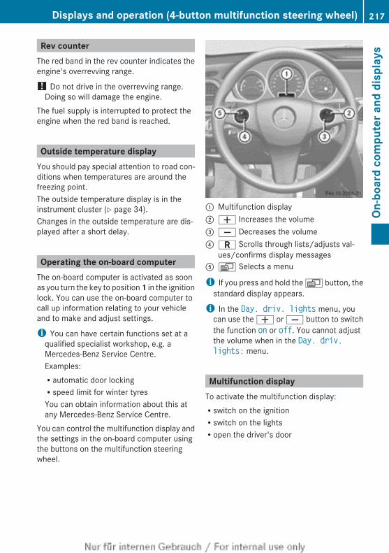
Rev counterThe red band in the rev counter indicates theengine's overrevving range.
! Do not drive in the overrevving range.Doing so will damage the engine.
The fuel supply is interrupted to protect theengine when the red band is reached.
Outside temperature displayYou should pay special attention to road con-ditions when temperatures are around thefreezing point.The outside temperature display is in theinstrument cluster (Y page 34).Changes in the outside temperature are dis-played after a short delay.
Operating the on-board computerThe on-board computer is activated as soonas you turn the key to position 1 in the ignitionlock. You can use the on-board computer tocall up information relating to your vehicleand to make and adjust settings.
i You can have certain functions set at aqualified specialist workshop, e.g. aMercedes-Benz Service Centre.Examples:Rautomatic door lockingRspeed limit for winter tyresYou can obtain information about this atany Mercedes-Benz Service Centre.
You can control the multifunction display andthe settings in the on-board computer usingthe buttons on the multifunction steeringwheel.
: Multifunction display; W Increases the volume= X Decreases the volume? C Scrolls through lists/adjusts val-
ues/confirms display messagesA V Selects a menu
i If you press and hold the V button, thestandard display appears.
i In the Day. driv. lights menu, youcan use the W or X button to switchthe function on or off. You cannot adjustthe volume when in the Day. driv. lights: menu.
Multifunction displayTo activate the multifunction display:Rswitch on the ignitionRswitch on the lightsRopen the driver's door
Displays and operation (4-button multifunction steering wheel) 217
On-b
oard
com
pute
r and
dis
play
s
Z
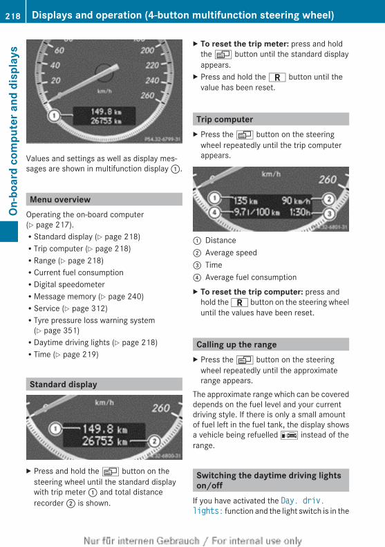
Values and settings as well as display mes-sages are shown in multifunction display :.
Menu overviewOperating the on-board computer(Y page 217).RStandard display (Y page 218)RTrip computer (Y page 218)RRange (Y page 218)RCurrent fuel consumptionRDigital speedometerRMessage memory (Y page 240)RService (Y page 312)RTyre pressure loss warning system
(Y page 351)RDaytime driving lights (Y page 218)RTime (Y page 219)
Standard display
X Press and hold the V button on thesteering wheel until the standard displaywith trip meter : and total distancerecorder ; is shown.
X To reset the trip meter: press and holdthe V button until the standard displayappears.
X Press and hold the C button until thevalue has been reset.
Trip computerX Press the V button on the steering
wheel repeatedly until the trip computerappears.
: Distance; Average speed= Time? Average fuel consumptionX To reset the trip computer: press and
hold the C button on the steering wheeluntil the values have been reset.
Calling up the rangeX Press the V button on the steering
wheel repeatedly until the approximaterange appears.
The approximate range which can be covereddepends on the fuel level and your currentdriving style. If there is only a small amountof fuel left in the fuel tank, the display showsa vehicle being refuelled C instead of therange.
Switching the daytime driving lightson/off
If you have activated the Day. driv. lights: function and the light switch is in the
218 Displays and operation (4-button multifunction steering wheel)On
-boa
rd c
ompu
ter a
nd d
ispl
ays
à position, the daytime driving lights areswitched on automatically when the engine isrunning. When it is dark, the side lamps andthe dipped-beam headlamps are switched onautomatically.On vehicles with daytime driving lamps, thefactory setting is on.If you want to change the setting for the Day. driv. lights: function, you have to turnthe key in the ignition lock to position 1.X Press the V button on the steering
wheel repeatedly until the Day. driv. lights: menu appears.You will see the selected setting: on oroff.
X Press the W or X button to changethe setting.
Time/datei Depending on your vehicle's equipment,
the time can be set using the on-boardcomputer or the audio system/COMAND,see the separate operating instructions.
X Press the V button on the steeringwheel repeatedly until the "Time/date"menu appears.
X To set: use the C button to select thedisplay you want to change: hour, minutes,day, month, year.
X Press W or X to set the selected dis-play.
X To save: press the C button.The next display is selected.
Displays and operation (12-buttonmultifunction steering wheel)
Instrument cluster lightingThe lighting in the instrument cluster, in thedisplays and the controls in the vehicle inte-rior can be adjusted using the brightness con-trol knob.
The brightness control knob is located on thebottom left of the instrument cluster(Y page 37).X Turn the brightness control knob clockwise
or anti-clockwise.If the light switch is set to Ã, T orL, the brightness is dependant uponthe brightness of the ambient light.
i The light sensor in the instrument clusterautomatically controls the brightness ofthe multifunction display.In daylight, the displays in the instrumentcluster are not illuminated.
Coolant temperature gauge
G WARNINGIf you open the bonnet while the engine isoverheating or while there is a fire in theengine compartment, you could come intocontact with hot gases or other leakingservice products. There is a danger of injury.Allow an overheating engine to cool downbefore opening the bonnet. If there is a fire inthe engine compartment, leave the bonnetclosed and notify the fire brigade.
The coolant temperature gauge is in theinstrument cluster on the left-hand side.Under normal operating conditions and withthe specified coolant level, the coolant tem-perature may rise to 120 †.At high outside temperatures and when driv-ing uphill, the coolant temperature may riseto the end of the scale.
Rev counterThe red band in the rev counter indicates theengine's overrevving range.
! Do not drive in the overrevving range.Doing so will damage the engine.
The fuel supply is interrupted to protect theengine when the red band is reached.
Displays and operation (12-button multifunction steering wheel) 219
On-b
oard
com
pute
r and
dis
play
s
Z
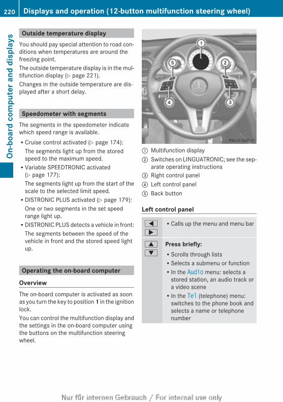
Outside temperature displayYou should pay special attention to road con-ditions when temperatures are around thefreezing point.The outside temperature display is in the mul-tifunction display (Y page 221).Changes in the outside temperature are dis-played after a short delay.
Speedometer with segmentsThe segments in the speedometer indicatewhich speed range is available.RCruise control activated (Y page 174):
The segments light up from the storedspeed to the maximum speed.RVariable SPEEDTRONIC activated
(Y page 177):The segments light up from the start of thescale to the selected limit speed.RDISTRONIC PLUS activated (Y page 179):
One or two segments in the set speedrange light up.RDISTRONIC PLUS detects a vehicle in front:
The segments between the speed of thevehicle in front and the stored speed lightup.
Operating the on-board computer
OverviewThe on-board computer is activated as soonas you turn the key to position 1 in the ignitionlock.You can control the multifunction display andthe settings in the on-board computer usingthe buttons on the multifunction steeringwheel.
: Multifunction display; Switches on LINGUATRONIC; see the sep-
arate operating instructions= Right control panel? Left control panelA Back button
Left control panel
=
;
RCalls up the menu and menu bar
9
:
Press briefly:RScrolls through listsRSelects a submenu or functionRIn the Audio menu: selects a
stored station, an audio track ora video sceneRIn the Tel (telephone) menu:
switches to the phone book andselects a name or telephonenumber
220 Displays and operation (12-button multifunction steering wheel)On
-boa
rd c
ompu
ter a
nd d
ispl
ays
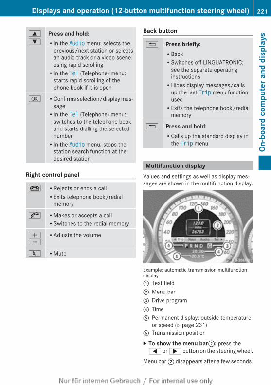
9
:
Press and hold:RIn the Audio menu: selects the
previous/next station or selectsan audio track or a video sceneusing rapid scrollingRIn the Tel (Telephone) menu:
starts rapid scrolling of thephone book if it is open
a RConfirms selection/display mes-sageRIn the Tel (Telephone) menu:
switches to the telephone bookand starts dialling the selectednumberRIn the Audio menu: stops the
station search function at thedesired station
Right control panel
~ RRejects or ends a callRExits telephone book/redial
memory
6 RMakes or accepts a callRSwitches to the redial memory
WX
RAdjusts the volume
8 RMute
Back button
% Press briefly:RBackRSwitches off LINGUATRONIC;
see the separate operatinginstructionsRHides display messages/calls
up the last Trip menu functionusedRExits the telephone book/redial
memory
% Press and hold:RCalls up the standard display in
the Trip menu
Multifunction displayValues and settings as well as display mes-sages are shown in the multifunction display.
Example: automatic transmission multifunctiondisplay: Text field; Menu bar= Drive program? TimeA Permanent display: outside temperature
or speed (Y page 231)B Transmission positionX To show the menu bar;: press the= or ; button on the steering wheel.
Menu bar ; disappears after a few seconds.
Displays and operation (12-button multifunction steering wheel) 221
On-b
oard
com
pute
r and
dis
play
s
Z
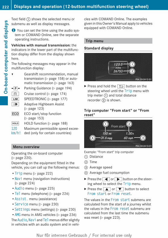
Text field : shows the selected menu orsubmenu as well as display messages.
i You can set the time using the audio sys-tem or COMAND Online, see the separateoperating instructions.
Vehicles with manual transmission: theindicators in the lower part of the multifunc-tion display differ from the display shownhere.The following messages may appear in themultifunction display:Z Gearshift recommendation, manual
transmission (Y page 158) or auto-matic transmission (Y page 163)
XjY Parking Guidance (Y page 194)¯ Cruise control (Y page 174)È SPEEDTRONIC (Y page 177)_ Adaptive Highbeam Assist
(Y page 123)¤ ECO start/stop function
(Y page 153)ë HOLD function (Y page 188)120 km/h!
Maximum permissible speed excee-ded (only for certain countries)
Menu overviewOperating the on-board computer(Y page 220).Depending on the equipment fitted in thevehicle, you can call up the following menus:RTrip menu (Y page 222)RNavi menu (navigation instructions)
(Y page 224)RAudio menu (Y page 225)RTel menu (telephone) (Y page 226)RAssist. menu (assistance)RService menu (Y page 230)RSettings menu (settings) (Y page 230)RAMG menu in AMG vehicles (Y page 236)The Audio, Navi and Tel menus differ slightlyin vehicles with an audio system and in vehi-
cles with COMAND Online. The examplesgiven in this Owner's Manual apply to vehiclesequipped with COMAND Online.
Trip menu
Standard display
X Press and hold the % button on thesteering wheel until the Trip menu withtrip meter : and total distancerecorder ; is shown.
Trip computer "From start" or "Fromreset"
Example: "From start" trip computer: Distance; Time= Average speed? Average fuel consumptionX Press the = or ; button on the steer-
ing wheel to select the Trip menu.X Press the 9 or : button to selectFrom start or From reset.
The values in the From start submenu arecalculated from the start of a journey whilstthe values in the From reset submenu arecalculated from the last time the submenuwas reset (Y page 223).
222 Displays and operation (12-button multifunction steering wheel)On
-boa
rd c
ompu
ter a
nd d
ispl
ays
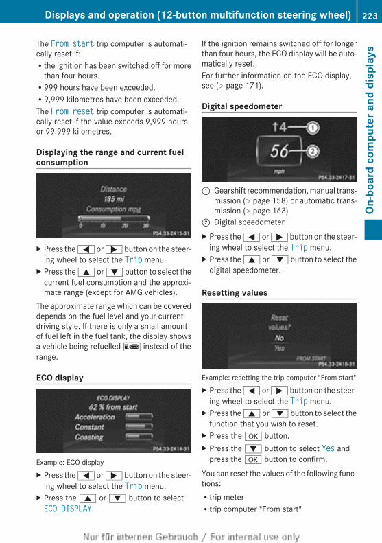
The From start trip computer is automati-cally reset if:Rthe ignition has been switched off for more
than four hours.R999 hours have been exceeded.R9,999 kilometres have been exceeded.The From reset trip computer is automati-cally reset if the value exceeds 9,999 hoursor 99,999 kilometres.
Displaying the range and current fuelconsumption
X Press the = or ; button on the steer-ing wheel to select the Trip menu.
X Press the 9 or : button to select thecurrent fuel consumption and the approxi-mate range (except for AMG vehicles).
The approximate range which can be covereddepends on the fuel level and your currentdriving style. If there is only a small amountof fuel left in the fuel tank, the display showsa vehicle being refuelled C instead of therange.
ECO display
Example: ECO displayX Press the = or ; button on the steer-
ing wheel to select the Trip menu.X Press the 9 or : button to selectECO DISPLAY.
If the ignition remains switched off for longerthan four hours, the ECO display will be auto-matically reset.For further information on the ECO display,see (Y page 171).
Digital speedometer
: Gearshift recommendation, manual trans-mission (Y page 158) or automatic trans-mission (Y page 163)
; Digital speedometerX Press the = or ; button on the steer-
ing wheel to select the Trip menu.X Press the 9 or : button to select the
digital speedometer.
Resetting values
Example: resetting the trip computer "From start"X Press the = or ; button on the steer-
ing wheel to select the Trip menu.X Press the 9 or : button to select the
function that you wish to reset.X Press the a button.X Press the : button to select Yes and
press the a button to confirm.
You can reset the values of the following func-tions:Rtrip meterRtrip computer "From start"
Displays and operation (12-button multifunction steering wheel) 223
On-b
oard
com
pute
r and
dis
play
s
Z
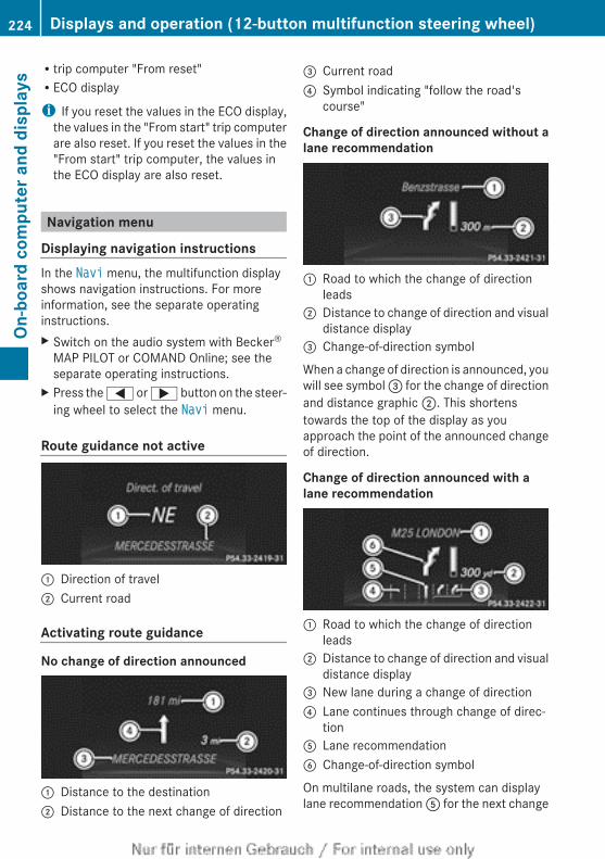
Rtrip computer "From reset"RECO display
i If you reset the values in the ECO display,the values in the "From start" trip computerare also reset. If you reset the values in the"From start" trip computer, the values inthe ECO display are also reset.
Navigation menu
Displaying navigation instructionsIn the Navi menu, the multifunction displayshows navigation instructions. For moreinformation, see the separate operatinginstructions.X Switch on the audio system with Becker®
MAP PILOT or COMAND Online; see theseparate operating instructions.
X Press the = or ; button on the steer-ing wheel to select the Navi menu.
Route guidance not active
: Direction of travel; Current road
Activating route guidance
No change of direction announced
: Distance to the destination; Distance to the next change of direction
= Current road? Symbol indicating "follow the road's
course"
Change of direction announced without alane recommendation
: Road to which the change of directionleads
; Distance to change of direction and visualdistance display
= Change-of-direction symbol
When a change of direction is announced, youwill see symbol = for the change of directionand distance graphic ;. This shortenstowards the top of the display as youapproach the point of the announced changeof direction.
Change of direction announced with alane recommendation
: Road to which the change of directionleads
; Distance to change of direction and visualdistance display
= New lane during a change of direction? Lane continues through change of direc-
tionA Lane recommendationB Change-of-direction symbol
On multilane roads, the system can displaylane recommendation A for the next change
224 Displays and operation (12-button multifunction steering wheel)On
-boa
rd c
ompu
ter a
nd d
ispl
ays
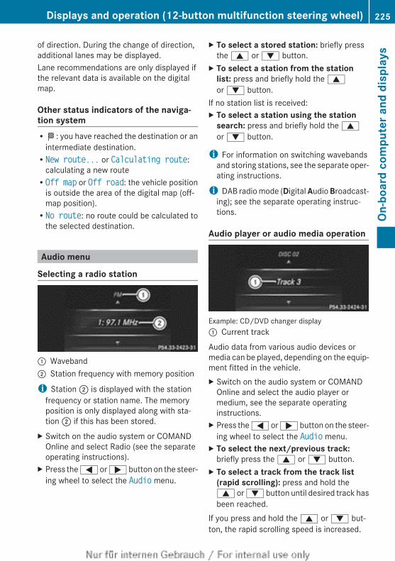
of direction. During the change of direction,additional lanes may be displayed.Lane recommendations are only displayed ifthe relevant data is available on the digitalmap.
Other status indicators of the naviga-tion systemRO: you have reached the destination or an
intermediate destination.RNew route... or Calculating route:
calculating a new routeROff map or Off road: the vehicle position
is outside the area of the digital map (off-map position).RNo route: no route could be calculated to
the selected destination.
Audio menu
Selecting a radio station
: Waveband; Station frequency with memory position
i Station ; is displayed with the stationfrequency or station name. The memoryposition is only displayed along with sta-tion ; if this has been stored.
X Switch on the audio system or COMANDOnline and select Radio (see the separateoperating instructions).
X Press the = or ; button on the steer-ing wheel to select the Audio menu.
X To select a stored station: briefly pressthe 9 or : button.
X To select a station from the station list: press and briefly hold the 9or : button.
If no station list is received:X To select a station using the station
search: press and briefly hold the 9or : button.
i For information on switching wavebandsand storing stations, see the separate oper-ating instructions.
i DAB radio mode (Digital Audio Broadcast-ing); see the separate operating instruc-tions.
Audio player or audio media operation
Example: CD/DVD changer display: Current track
Audio data from various audio devices ormedia can be played, depending on the equip-ment fitted in the vehicle.X Switch on the audio system or COMAND
Online and select the audio player ormedium, see the separate operatinginstructions.
X Press the = or ; button on the steer-ing wheel to select the Audio menu.
X To select the next/previous track:briefly press the 9 or : button.
X To select a track from the track list (rapid scrolling): press and hold the9 or : button until desired track hasbeen reached.
If you press and hold the 9 or : but-ton, the rapid scrolling speed is increased.
Displays and operation (12-button multifunction steering wheel) 225
On-b
oard
com
pute
r and
dis
play
s
Z
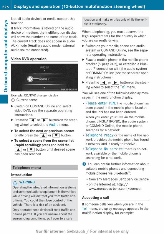
Not all audio devices or media support thisfunction.If track information is stored on the audiodevice or medium, the multifunction displaywill show the number and name of the track.The current track does not appear in audioAUX mode (Auxiliary audio mode: externalaudio source connected).
Video DVD operation
Example: CD/DVD changer display: Current sceneX Switch on COMAND Online and select
video DVD; see the separate operatinginstructions.
X Press the = or ; button on the steer-ing wheel to select the Audio menu.
X To select the next or previous scene:briefly press the 9 or : button.
X To select a scene from the scene list (rapid scrolling): press and hold the9 or : button until desired scenehas been reached.
Telephone menu
Introduction
G WARNINGOperating the integrated information systemsand communications equipment in the vehiclewhile driving will distract you from traffic con-ditions. You could then lose control of thevehicle. There is a risk of an accident.Only operate these devices if road traffic con-ditions permit. If you are unsure about thesurrounding conditions, pull over to a safe
location and make entries only while the vehi-cle is stationary.
When telephoning, you must observe thelegal requirements for the country in whichyou are currently driving.X Switch on your mobile phone and audio
system or COMAND Online, see the sepa-rate operating instructions.
X Place a mobile phone in the mobile phonebracket (Y page 302), or establish a Blue-tooth® connection with the audio systemor COMAND Online (see the separate oper-ating instructions).
X Press the = or ; button on the steer-ing wheel to select the Tel menu.
You will see one of the following display mes-sages in the multifunction display:RPlease enter PIN: the mobile phone has
been placed in the mobile phone bracketand the PIN has not been entered.When you enter your PIN via the mobilephone, LINGUATRONIC, the audio systemor COMAND Online, the mobile phonesearches for a network.RTelephone ready or the name of the net-
work provider: the mobile phone has founda network and is ready to receive.RTelephone No service: there is no net-
work available or the mobile phone issearching for a network.
i You can obtain further information aboutsuitable mobile phones and connectingmobile phones via Bluetooth®:Rfrom any Mercedes Benz Service CentreRon the Internet at: http://
www.mercedes-benz.com/connect
Accepting a callIf someone calls you when you are in theTel menu, a display message appears in themultifunction display, for example:
226 Displays and operation (12-button multifunction steering wheel)On
-boa
rd c
ompu
ter a
nd d
ispl
ays
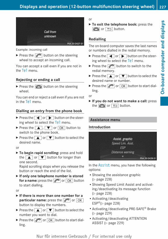
Example: incoming callX Press the 6 button on the steering
wheel to accept an incoming call.You can accept a call even if you are not inthe Tel menu.
Rejecting or ending a callX Press the ~ button on the steering
wheel.You can end or reject a call even if you are notin the Tel menu.
Dialling an entry from the phone bookX Press the = or ; button on the steer-
ing wheel to select the Tel menu.X Press the 9, : or a button to
switch to the phone book.X Press the 9 or : button to select the
desired name.orX To begin rapid scrolling: press and hold
the 9 or : button for longer thanone second.Rapid scrolling stops when you release thebutton or reach the end of the list.
X If only one telephone number is stored for a name: press the 6 or a buttonto start dialling.
orX If there is more than one number for a
particular name: press the 6 or abutton to display the numbers.
X Press the 9 or : button to select thenumber you want to dial.
X Press the 6 or a button to start dial-ling.
orX To exit the telephone book: press the~ or % button.
RediallingThe on-board computer saves the last namesor numbers dialled in the redial memory.X Press the = or ; button on the steer-
ing wheel to select the Tel menu.X Press the 6 button to switch to the
redial memory.X Press the 9 or : button to select the
desired name or number.X Press the 6 or a button to start dial-
ling.orX If you do not want to make a call: press
the ~ or % button.
Assistance menu
Introduction
In the Assist menu, you have the followingoptions:RShowing the assistance graphic
(Y page 228)RShowing Speed Limit Assist and activat-
ing/deactivating its message function(Y page 228)RActivating/deactivating
ESP®(Y page 228)RActivating/deactivating PRE-SAFE® Brake
(Y page 229)RActivating/deactivating ATTENTION
ASSIST (Y page 229)
Displays and operation (12-button multifunction steering wheel) 227
On-b
oard
com
pute
r and
dis
play
s
Z
RActivating/deactivating Blind Spot Assistor Active Blind Spot Assist (Y page 229)RActivating/deactivating Lane Keeping
Assist or Active Lane Keeping Assist(Y page 230)
Showing the assistance graphicX Press the = or ; button on the steer-
ing wheel to select the Assist menu.X Press 9 or : to select Assistance graphic.
X Press the a button.The multifunction display shows the DIS-TRONIC PLUS distance display in the assis-tance graphic (Y page 185).
The assistance graphic can display the statusof and information from other driving systemsor driving safety systems.The assistance graphic shows:Rthe é symbol when ATTENTION ASSIST
(Y page 198) is deactivated.Rthe lane markings as bright lines when Lane
Keeping Assist (Y page 202) or Active LaneKeeping Assist (Y page 206) is activated.Rthe Ä symbol when Speed Limit Assist
(Y page 198) is operational.The assistance graphic can also displaytraffic signs that are detected and indicatespeed limits.Rthe æ symbol when PRE-SAFE® Brake
(Y page 77) is deactivated.
Speed Limit Assist
Displaying Speed Limit AssistX Press the = or ; button on the steer-
ing wheel to select the Assist menu.X Press the 9 or : button to selectSpeed Lim. Asst..
X Press the a button.Under certain conditions, detected speedlimits are shown in the multifunction dis-play (Y page 198).
Activating/deactivating the Speed LimitAssist message functionX Press the = or ; button on the steer-
ing wheel to select the Assist menu.X Press the 9 or : button to selectSpeed Lim. Asst.
X Press the a button.The multifunction display shows SpeedLimit Assist.
X Press the : button.The current selection is displayed.
X To activate or deactivate: press a.If the Speed Limit Assist message functionis activated, a detected speed limit is auto-matically displayed for five seconds. Otheritems in the multifunction display are notshown during this time.When Speed Limit Assist is operational andthe message function is activated, theassistance graphic shows the Ä sym-bol.
Deactivating/activating ESP®
i Observe the "Important safety notes" sec-tion in the description of ESP (Y page 73).
G WARNINGIf you deactivate ESP®, ESP® no longer sta-bilises the vehicle. There is an increased riskof skidding and an accident.Only deactivate ESP® in the situations descri-bed in the following.
It may be best to deactivate ESP® in the fol-lowing situations:Rwhen using snow chainsRin deep snowRon sand or gravelDeactivating/activating ESP® on AMG vehi-cles (Y page 75).For further information about ESP®, see(Y page 73).
228 Displays and operation (12-button multifunction steering wheel)On
-boa
rd c
ompu
ter a
nd d
ispl
ays
X Start the engine.X Press the = or ; button on the steer-
ing wheel to select the Assist menu.X Press the 9 or : button to selectESP.
X Press the a button.X To deactivate: press a again.
The å warning lamp in the instrumentcluster lights up.
X To activate: press a again.The å warning lamp in the instrumentcluster goes out.
ESP® is deactivated if the å warning lampin the instrument cluster lights up continu-ously when the engine is running.If the ÷ warning lamp and the å warn-ing lamp are lit continuously, ESP® is notavailable due to a malfunction.Observe the information on warning lamps(Y page 284).Observe the information on display messages(Y page 247).
Activating/deactivating PRE-SAFE®
BrakePRE-SAFE® Brake is only available in vehicleswith DISTRONIC PLUS.X Press the = or ; button on the steer-
ing wheel to select the Assist menu.X Press the 9 or : button to selectPRE-SAFE Brake.
X Press the a button.The current selection is displayed.
X To activate/deactivate: press the abutton again.When PRE-SAFE® Brake is deactivated, theassistance graphic shows the æ symbolin the multifunction display.
If the PRE-SAFE Brake: Sensors deacti‐vated message appears, the radar sensorsystem is deactivated.
X Switch on the radar sensor system(Y page 234).
For more information on PRE-SAFE® Brake,see (Y page 77).
Activating/deactivating ATTENTIONASSISTX Press the = or ; button on the steer-
ing wheel to select the Assist menu.X Press the 9 or : button to selectAttention Assist.
X Press the a button.The current selection is displayed.
X To activate/deactivate: press the abutton again.When ATTENTION ASSIST is deactivated,the é symbol appears in the multifunc-tion display in the assistance graphics dis-play.
For further information about ATTENTIONASSIST, see (Y page 198).
Activating/deactivating Blind SpotAssistX Press the = or ; button on the steer-
ing wheel to select the Assist menu.X Press the 9 or : button to selectBlind Spot Assist.
X Press the a button.The current selection is displayed.
X To activate/deactivate: press the abutton again.
If the Blind Spot Assist Sensors deac‐tivated or Act. B. Spot Assist Sen‐sors deactivated message appears, theradar sensor system is deactivated.X Switch on the radar sensor system
(Y page 234).For further information about Blind SpotAssist, see (Y page 200).For further information about Active BlindSpot Assist, see (Y page 203).
Displays and operation (12-button multifunction steering wheel) 229
On-b
oard
com
pute
r and
dis
play
s
Z
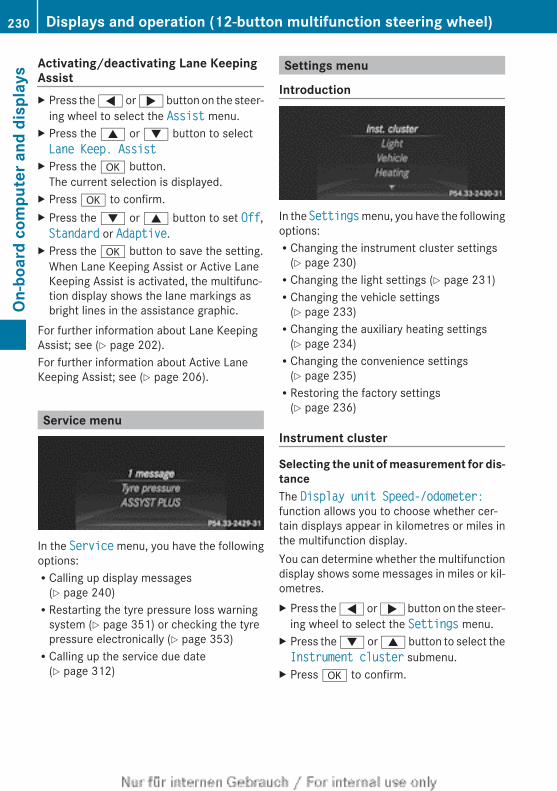
Activating/deactivating Lane KeepingAssistX Press the = or ; button on the steer-
ing wheel to select the Assist menu.X Press the 9 or : button to selectLane Keep. Assist
X Press the a button.The current selection is displayed.
X Press a to confirm.X Press the : or 9 button to set Off,Standard or Adaptive.
X Press the a button to save the setting.When Lane Keeping Assist or Active LaneKeeping Assist is activated, the multifunc-tion display shows the lane markings asbright lines in the assistance graphic.
For further information about Lane KeepingAssist; see (Y page 202).For further information about Active LaneKeeping Assist; see (Y page 206).
Service menu
In the Service menu, you have the followingoptions:RCalling up display messages
(Y page 240)RRestarting the tyre pressure loss warning
system (Y page 351) or checking the tyrepressure electronically (Y page 353)RCalling up the service due date
(Y page 312)
Settings menu
Introduction
In the Settings menu, you have the followingoptions:RChanging the instrument cluster settings
(Y page 230)RChanging the light settings (Y page 231)RChanging the vehicle settings
(Y page 233)RChanging the auxiliary heating settings
(Y page 234)RChanging the convenience settings
(Y page 235)RRestoring the factory settings
(Y page 236)
Instrument cluster
Selecting the unit of measurement for dis-tanceThe Display unit Speed-/odometer:function allows you to choose whether cer-tain displays appear in kilometres or miles inthe multifunction display.You can determine whether the multifunctiondisplay shows some messages in miles or kil-ometres.X Press the = or ; button on the steer-
ing wheel to select the Settings menu.X Press the : or 9 button to select theInstrument cluster submenu.
X Press a to confirm.
230 Displays and operation (12-button multifunction steering wheel)On
-boa
rd c
ompu
ter a
nd d
ispl
ays
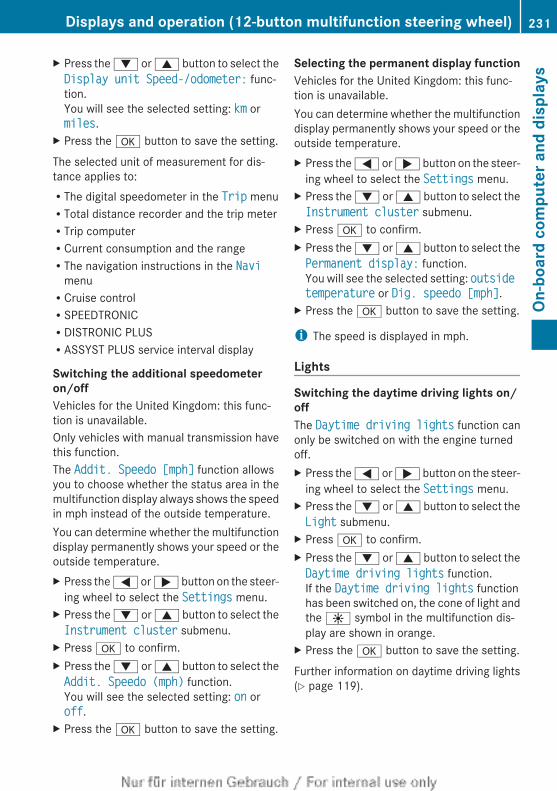
X Press the : or 9 button to select theDisplay unit Speed-/odometer: func-tion.You will see the selected setting: km ormiles.
X Press the a button to save the setting.
The selected unit of measurement for dis-tance applies to:RThe digital speedometer in the Trip menuRTotal distance recorder and the trip meterRTrip computerRCurrent consumption and the rangeRThe navigation instructions in the Navi
menuRCruise controlRSPEEDTRONICRDISTRONIC PLUSRASSYST PLUS service interval display
Switching the additional speedometeron/offVehicles for the United Kingdom: this func-tion is unavailable.Only vehicles with manual transmission havethis function.The Addit. Speedo [mph] function allowsyou to choose whether the status area in themultifunction display always shows the speedin mph instead of the outside temperature.You can determine whether the multifunctiondisplay permanently shows your speed or theoutside temperature.X Press the = or ; button on the steer-
ing wheel to select the Settings menu.X Press the : or 9 button to select theInstrument cluster submenu.
X Press a to confirm.X Press the : or 9 button to select theAddit. Speedo (mph) function.You will see the selected setting: on oroff.
X Press the a button to save the setting.
Selecting the permanent display functionVehicles for the United Kingdom: this func-tion is unavailable.You can determine whether the multifunctiondisplay permanently shows your speed or theoutside temperature.X Press the = or ; button on the steer-
ing wheel to select the Settings menu.X Press the : or 9 button to select theInstrument cluster submenu.
X Press a to confirm.X Press the : or 9 button to select thePermanent display: function.You will see the selected setting: outside temperature or Dig. speedo [mph].
X Press the a button to save the setting.
i The speed is displayed in mph.
Lights
Switching the daytime driving lights on/offThe Daytime driving lights function canonly be switched on with the engine turnedoff.X Press the = or ; button on the steer-
ing wheel to select the Settings menu.X Press the : or 9 button to select theLight submenu.
X Press a to confirm.X Press the : or 9 button to select theDaytime driving lights function.If the Daytime driving lights functionhas been switched on, the cone of light andthe W symbol in the multifunction dis-play are shown in orange.
X Press the a button to save the setting.
Further information on daytime driving lights(Y page 119).
Displays and operation (12-button multifunction steering wheel) 231
On-b
oard
com
pute
r and
dis
play
s
Z
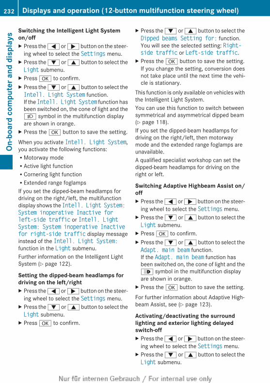
Switching the Intelligent Light Systemon/offX Press the = or ; button on the steer-
ing wheel to select the Settings menu.X Press the : or 9 button to select theLight submenu.
X Press a to confirm.X Press the : or 9 button to select theIntell. Light System function.If the Intell. Light System function hasbeen switched on, the cone of light and theL symbol in the multifunction displayare shown in orange.
X Press the a button to save the setting.
When you activate Intell. Light System,you activate the following functions:RMotorway modeRActive light functionRCornering light functionRExtended range foglampsIf you set the dipped-beam headlamps fordriving on the right/left, the multifunctiondisplay shows the Intell. Light System: System inoperative Inactive for left-side traffic or Intell. Light System: System inoperative Inactive for right-side traffic display messageinstead of the Intell. Light System:function in the Light submenu.Further information on the Intelligent LightSystem (Y page 122).
Setting the dipped-beam headlamps fordriving on the left/rightX Press the = or ; button on the steer-
ing wheel to select the Settings menu.X Press the : or 9 button to select theLight submenu.
X Press a to confirm.
X Press the : or 9 button to select theDipped beams Setting for: function.You will see the selected setting: Right-side traffic or Left-side traffic.
X Press the a button to save the setting.If you change the setting, conversion doesnot take place until the next time the vehi-cle is stationary.
This function is only available on vehicles withthe Intelligent Light System.You can use this function to switch betweensymmetrical and asymmetrical dipped beam(Y page 118).If you set the dipped-beam headlamps fordriving on the right/left, then motorwaymode and the extended range foglamps areunavailable.A qualified specialist workshop can set thedipped-beam headlamps for driving on theright or left.
Switching Adaptive Highbeam Assist on/offX Press the = or ; button on the steer-
ing wheel to select the Settings menu.X Press the : or 9 button to select theLight submenu.
X Press a to confirm.X Press the : or 9 button to select theAdapt. main beam function.If the Adapt. main beam function hasbeen switched on, the cone of light and the_ symbol in the multifunction displayare shown in orange.
X Press the a button to save the setting.
For further information about Adaptive High-beam Assist, see (Y page 123).
Activating/deactivating the surroundlighting and exterior lighting delayedswitch-offX Press the = or ; button on the steer-
ing wheel to select the Settings menu.X Press the : or 9 button to select theLight submenu.
232 Displays and operation (12-button multifunction steering wheel)On
-boa
rd c
ompu
ter a
nd d
ispl
ays
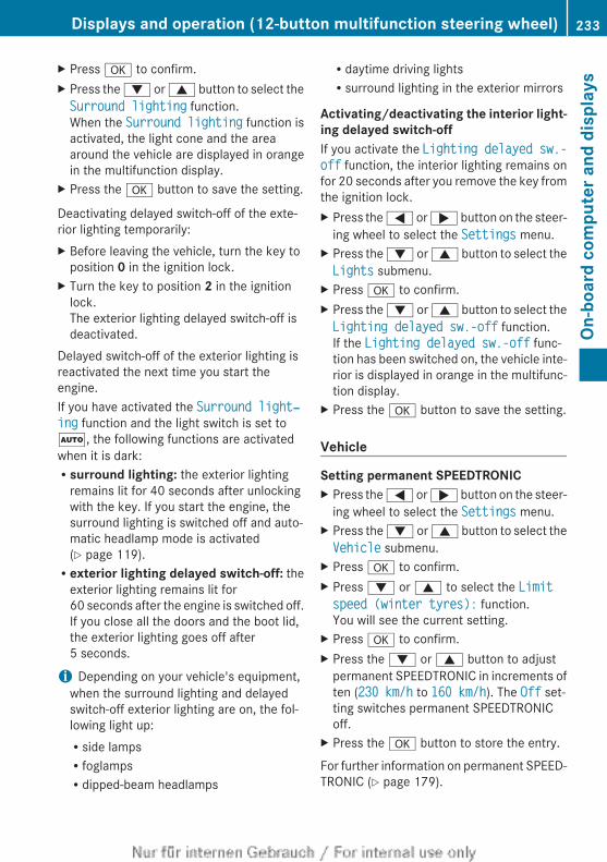
X Press a to confirm.X Press the : or 9 button to select theSurround lighting function.When the Surround lighting function isactivated, the light cone and the areaaround the vehicle are displayed in orangein the multifunction display.
X Press the a button to save the setting.
Deactivating delayed switch-off of the exte-rior lighting temporarily:X Before leaving the vehicle, turn the key to
position 0 in the ignition lock.X Turn the key to position 2 in the ignition
lock.The exterior lighting delayed switch-off isdeactivated.
Delayed switch-off of the exterior lighting isreactivated the next time you start theengine.If you have activated the Surround light‐ing function and the light switch is set toÃ, the following functions are activatedwhen it is dark:Rsurround lighting: the exterior lighting
remains lit for 40 seconds after unlockingwith the key. If you start the engine, thesurround lighting is switched off and auto-matic headlamp mode is activated(Y page 119).Rexterior lighting delayed switch-off: the
exterior lighting remains lit for60 seconds after the engine is switched off.If you close all the doors and the boot lid,the exterior lighting goes off after5 seconds.
i Depending on your vehicle's equipment,when the surround lighting and delayedswitch-off exterior lighting are on, the fol-lowing light up:Rside lampsRfoglampsRdipped-beam headlamps
Rdaytime driving lightsRsurround lighting in the exterior mirrors
Activating/deactivating the interior light-ing delayed switch-offIf you activate the Lighting delayed sw.-off function, the interior lighting remains onfor 20 seconds after you remove the key fromthe ignition lock.X Press the = or ; button on the steer-
ing wheel to select the Settings menu.X Press the : or 9 button to select theLights submenu.
X Press a to confirm.X Press the : or 9 button to select theLighting delayed sw.-off function.If the Lighting delayed sw.-off func-tion has been switched on, the vehicle inte-rior is displayed in orange in the multifunc-tion display.
X Press the a button to save the setting.
Vehicle
Setting permanent SPEEDTRONICX Press the = or ; button on the steer-
ing wheel to select the Settings menu.X Press the : or 9 button to select theVehicle submenu.
X Press a to confirm.X Press : or 9 to select the Limit speed (winter tyres): function.You will see the current setting.
X Press a to confirm.X Press the : or 9 button to adjust
permanent SPEEDTRONIC in increments often (230 km/h to 160 km/h). The Off set-ting switches permanent SPEEDTRONICoff.
X Press the a button to store the entry.
For further information on permanent SPEED-TRONIC (Y page 179).
Displays and operation (12-button multifunction steering wheel) 233
On-b
oard
com
pute
r and
dis
play
s
Z
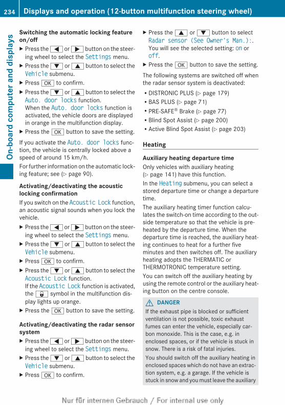
Switching the automatic locking featureon/offX Press the = or ; button on the steer-
ing wheel to select the Settings menu.X Press the : or 9 button to select theVehicle submenu.
X Press a to confirm.X Press the : or 9 button to select theAuto. door locks function.When the Auto. door locks function isactivated, the vehicle doors are displayedin orange in the multifunction display.
X Press the a button to save the setting.
If you activate the Auto. door locks func-tion, the vehicle is centrally locked above aspeed of around 15 km/h.For further information on the automatic lock-ing feature; see (Y page 90).
Activating/deactivating the acousticlocking confirmationIf you switch on the Acoustic Lock function,an acoustic signal sounds when you lock thevehicle.X Press the = or ; button on the steer-
ing wheel to select the Settings menu.X Press the : or 9 button to select theVehicle submenu.
X Press a to confirm.X Press the : or 9 button to select theAcoustic Lock function.If the Acoustic Lock function is activated,the & symbol in the multifunction dis-play lights up orange.
X Press the a button to save the setting.
Activating/deactivating the radar sensorsystemX Press the = or ; button on the steer-
ing wheel to select the Settings menu.X Press the : or 9 button to select theVehicle submenu.
X Press a to confirm.
X Press the 9 or : button to selectRadar sensor (See Owner's Man.):.You will see the selected setting: on oroff.
X Press the a button to save the setting.
The following systems are switched off whenthe radar sensor system is deactivated:RDISTRONIC PLUS (Y page 179)RBAS PLUS (Y page 71)RPRE-SAFE® Brake (Y page 77)RBlind Spot Assist (Y page 200)RActive Blind Spot Assist (Y page 203)
Heating
Auxiliary heating departure timeOnly vehicles with auxiliary heating(Y page 141) have this function.In the Heating submenu, you can select astored departure time or change a departuretime.The auxiliary heating timer function calcu-lates the switch-on time according to the out-side temperature so that the vehicle is pre-heated by the departure time. When thedeparture time is reached, the auxiliary heat-ing continues to heat for a further fiveminutes and then switches off. The auxiliaryheating adopts the THERMATIC orTHERMOTRONIC temperature setting.You can switch off the auxiliary heating byusing the remote control or the auxiliary heat-ing button on the centre console.
G DANGERIf the exhaust pipe is blocked or sufficientventilation is not possible, toxic exhaustfumes can enter the vehicle, especially car-bon monoxide. This is the case, e.g. inenclosed spaces, or if the vehicle is stuck insnow. There is a risk of fatal injuries.You should switch off the auxiliary heating inenclosed spaces which do not have an extrac-tion system, e.g. a garage. If the vehicle isstuck in snow and you must leave the auxiliary
234 Displays and operation (12-button multifunction steering wheel)On
-boa
rd c
ompu
ter a
nd d
ispl
ays
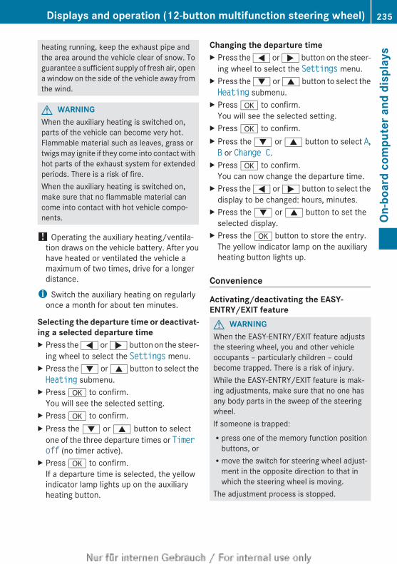
heating running, keep the exhaust pipe andthe area around the vehicle clear of snow. Toguarantee a sufficient supply of fresh air, opena window on the side of the vehicle away fromthe wind.
G WARNINGWhen the auxiliary heating is switched on,parts of the vehicle can become very hot.Flammable material such as leaves, grass ortwigs may ignite if they come into contact withhot parts of the exhaust system for extendedperiods. There is a risk of fire.When the auxiliary heating is switched on,make sure that no flammable material cancome into contact with hot vehicle compo-nents.
! Operating the auxiliary heating/ventila-tion draws on the vehicle battery. After youhave heated or ventilated the vehicle amaximum of two times, drive for a longerdistance.
i Switch the auxiliary heating on regularlyonce a month for about ten minutes.
Selecting the departure time or deactivat-ing a selected departure timeX Press the = or ; button on the steer-
ing wheel to select the Settings menu.X Press the : or 9 button to select theHeating submenu.
X Press a to confirm.You will see the selected setting.
X Press a to confirm.X Press the : or 9 button to select
one of the three departure times or Timer off (no timer active).
X Press a to confirm.If a departure time is selected, the yellowindicator lamp lights up on the auxiliaryheating button.
Changing the departure timeX Press the = or ; button on the steer-
ing wheel to select the Settings menu.X Press the : or 9 button to select theHeating submenu.
X Press a to confirm.You will see the selected setting.
X Press a to confirm.X Press the : or 9 button to select A,B or Change C.
X Press a to confirm.You can now change the departure time.
X Press the = or ; button to select thedisplay to be changed: hours, minutes.
X Press the : or 9 button to set theselected display.
X Press the a button to store the entry.The yellow indicator lamp on the auxiliaryheating button lights up.
Convenience
Activating/deactivating the EASY-ENTRY/EXIT featureG WARNINGWhen the EASY-ENTRY/EXIT feature adjuststhe steering wheel, you and other vehicleoccupants – particularly children – couldbecome trapped. There is a risk of injury.While the EASY-ENTRY/EXIT feature is mak-ing adjustments, make sure that no one hasany body parts in the sweep of the steeringwheel.If someone is trapped:Rpress one of the memory function position
buttons, orRmove the switch for steering wheel adjust-
ment in the opposite direction to that inwhich the steering wheel is moving.
The adjustment process is stopped.
Displays and operation (12-button multifunction steering wheel) 235
On-b
oard
com
pute
r and
dis
play
s
Z
X Press the = or ; button on the steer-ing wheel to select the Settings menu.
X Press the : or 9 button to select theConvenience submenu.
X Press a to confirm.X Press the : or 9 button to select theEasy Entry/Exit: function.If the Easy Entry/Exit function is activa-ted, the vehicle steering wheel is displayedin orange in the multifunction display.
X Press the a button to save the setting.
Further information on the EASY-ENTRY/EXITfeature (Y page 111).
Switching belt adjustment on/offX Press the = or ; button on the steer-
ing wheel to select the Settings menu.X Press the : or 9 button to select theConvenience submenu.
X Press a to confirm.X Press the : or 9 button to select theBelt adjustment function.When the Belt adjustment function isactivated, the vehicle seat belt is displayedin orange in the multifunction display.
X Press the a button to save the setting.
For further information on belt adjustment,see (Y page 57).
Switching the fold in mirrors when lock-ing function on/offThis function is only available on vehicles witha memory function (Y page 115).When you activate the Auto. fold in func-tion, the exterior mirrors are folded in whenthe vehicle is locked. When you unlock thevehicle and then open a door, the exteriormirrors fold out again.X Press the = or ; button on the steer-
ing wheel to select the Settings menu.X Press the : or 9 button to select theConvenience submenu.
X Press a to confirm.
X Press the : or 9 button to select theAuto. fold in function.If the Auto. fold in function is activated,the vehicle's exterior mirror is displayed inorange in the multifunction display.
X Press the a button to save the setting.
If you have switched the Auto. fold infunction on and you fold the exterior mirrorsin using the button on the door(Y page 113), they will not fold out automat-ically. The exterior mirrors can then only befolded out using the button on the door.
Resetting to factory settingsX Press the = or ; button on the steer-
ing wheel to select the Settings menu.X Press the : or 9 button to select theFactory settings submenu.
X Press a to confirm.The Reset all settings? messageappears.
X Press the : or 9 button to selectNo or Yes.
X Press the a button to confirm the selec-tion.If you have selected Yes, the multifunctiondisplay shows a confirmation message.
For safety reasons, not all functions are reset:the Limit speed (winter tyres): func-tion in permanent SPEEDTRONIC can only beset in the Vehicle submenu. If you want toreset the Daytime driving lights in theLight submenu, you must turn the key toposition 1 in the ignition lock.
AMG menu in AMG vehicles
AMG displaysX Press = or ; on the steering wheel
to select the AMG menu.
236 Displays and operation (12-button multifunction steering wheel)On
-boa
rd c
ompu
ter a
nd d
ispl
ays
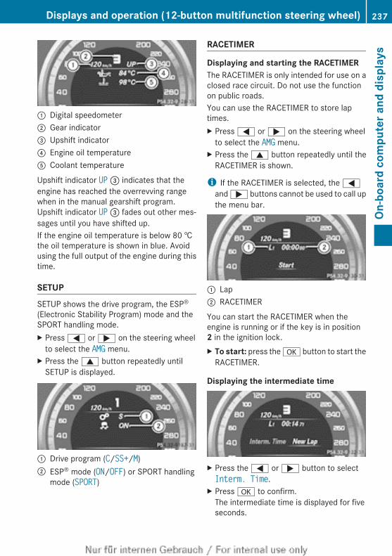
: Digital speedometer; Gear indicator= Upshift indicator? Engine oil temperatureA Coolant temperature
Upshift indicator UP = indicates that theengine has reached the overrevving rangewhen in the manual gearshift program.Upshift indicator UP = fades out other mes-sages until you have shifted up.If the engine oil temperature is below 80 †the oil temperature is shown in blue. Avoidusing the full output of the engine during thistime.
SETUPSETUP shows the drive program, the ESP®
(Electronic Stability Program) mode and theSPORT handling mode.X Press = or ; on the steering wheel
to select the AMG menu.X Press the 9 button repeatedly until
SETUP is displayed.
: Drive program (C/SS+/M); ESP® mode (ON/OFF) or SPORT handling
mode (SPORT)
RACETIMER
Displaying and starting the RACETIMERThe RACETIMER is only intended for use on aclosed race circuit. Do not use the functionon public roads.You can use the RACETIMER to store laptimes.X Press = or ; on the steering wheel
to select the AMG menu.X Press the 9 button repeatedly until the
RACETIMER is shown.
i If the RACETIMER is selected, the =and ; buttons cannot be used to call upthe menu bar.
: Lap; RACETIMER
You can start the RACETIMER when theengine is running or if the key is in position2 in the ignition lock.X To start: press the a button to start the
RACETIMER.
Displaying the intermediate time
X Press the = or ; button to selectInterm. Time.
X Press a to confirm.The intermediate time is displayed for fiveseconds.
Displays and operation (12-button multifunction steering wheel) 237
On-b
oard
com
pute
r and
dis
play
s
Z
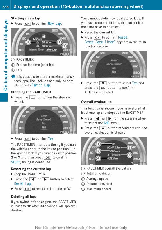
Starting a new lapX Press a to confirm New Lap.
: RACETIMER; Fastest lap time (best lap)= Lap
i It is possible to store a maximum of six-teen laps. The 16th lap can only be com-pleted with Finish Lap.
Stopping the RACETIMERX Press the % button on the steering
wheel.
X Press a to confirm Yes.
The RACETIMER interrupts timing if you stopthe vehicle and turn the key to position 1 inthe ignition lock. If you turn the key to position2 or 3 and then press a to confirmStart, timing is continued.
Resetting the current lapX Stop the RACETIMER.X Press the = or ; button to selectReset Lap.
X Press a to reset the lap time to "0".
Deleting all lapsIf you switch off the engine, the RACETIMERis reset to "0" after 30 seconds. All laps aredeleted.
You cannot delete individual stored laps. Ifyou have stopped 16 laps, the current lapdoes not have to be reset.X Reset the current lap.X Press a to confirm Reset.Reset Race Timer? appears in the multi-function display.
X Press the : button to select Yes andpress the a button to confirm.All laps are deleted.
Overall evaluationThis function is shown if you have stored atleast one lap and stopped the RACETIMER.X Press = or ; on the steering wheel
to select the AMG menu.X Press the 9 button repeatedly until the
overall evaluation is shown.
: RACETIMER overall evaluation; Total time driven= Average speed? Distance coveredA Maximum speed
238 Displays and operation (12-button multifunction steering wheel)On
-boa
rd c
ompu
ter a
nd d
ispl
ays
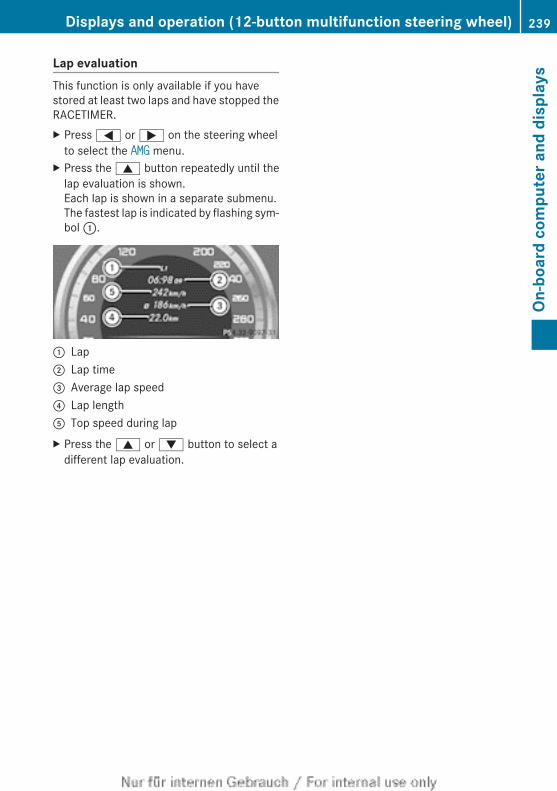
Lap evaluationThis function is only available if you havestored at least two laps and have stopped theRACETIMER.X Press = or ; on the steering wheel
to select the AMG menu.X Press the 9 button repeatedly until the
lap evaluation is shown.Each lap is shown in a separate submenu.The fastest lap is indicated by flashing sym-bol :.
: Lap; Lap time= Average lap speed? Lap lengthA Top speed during lapX Press the 9 or : button to select a
different lap evaluation.
Displays and operation (12-button multifunction steering wheel) 239
On-b
oard
com
pute
r and
dis
play
s
Z
Display messages
General notesDisplay messages appear in the multifunction display.Display messages with graphic symbols are simplified in the Owner's Manual and may differfrom the symbols in the multifunction display.Please respond in accordance with the display messages and follow the additional notes inthis Owner's Manual.Certain display messages are accompanied by an audible warning tone or a continuous tone.When the ignition is switched off, all display messages are deleted apart from some high-priority display messages. Once the causes of the high-priority display messages have beenrectified, the corresponding display messages are also deleted.When you stop and park the vehicle, please observe the notes on the HOLD function(Y page 188) and parking (Y page 169).
Hiding display messagesX Vehicles with a 4-button multifunction steering wheel: press C on the steering
wheel to clear the display message.The display message is cleared.
X Vehicles with a 12-button multifunction steering wheel: press a or % on thesteering wheel to clear the display message.The display message is cleared.
The multifunction display shows high-priority display messages in red. Some high-priority dis-play messages cannot be hidden.The multifunction display shows these messages continuously until the causes for the mes-sages have been remedied.
Message memory
Vehicles with a 4-button multifunction steering wheelThe on-board computer saves certain display messages. You can call up these display mes-sages in the message memory.X Press the V button on the steering wheel repeatedly until the message memory is
shown.If there are no display messages, you will see No messages. If there are display messages,the multifunction display shows, 2 messages, for example.
X Using the C button, scroll through the display messages.For some display messages, the + symbol appears in the multifunction display. You willfind detailed information about these display messages in the section which follows.
240 Display messagesOn
-boa
rd c
ompu
ter a
nd d
ispl
ays
Vehicles with a 12-button multifunction steering wheelThe on-board computer saves certain display messages. You can call up the display messagesin the message memory.X Press the = or ; button on the steering wheel to select the Service menu.
If there are display messages, the multifunction display shows 2 messages, for example.X Press the 9 or : button to select the entry, e.g. 2 messages.X Press a to confirm.X Press the 9 or : button to scroll through the display messages.
Display messages 241
On-b
oard
com
pute
r and
dis
play
s
Z
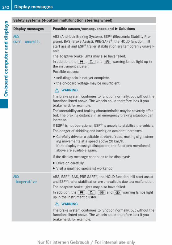
Safety systems (4-button multifunction steering wheel)
Display messages Possible causes/consequences and M Solutions
ABScurr. unavail.
ABS (Anti-lock Braking System), ESP® (Electronic Stability Pro-gram), BAS (Brake Assist), PRE-SAFE®, the HOLD function, hillstart assist and ESP® trailer stabilisation are temporarily unavail-able.The adaptive brake lights may also have failed.In addition, the ÷, å and ! warning lamps light up inthe instrument cluster.Possible causes:Rself-diagnosis is not yet complete.Rthe on-board voltage may be insufficient.
G WARNINGThe brake system continues to function normally, but without thefunctions listed above. The wheels could therefore lock if youbrake hard, for example.The steerability and braking characteristics may be severely affec-ted. The braking distance in an emergency braking situation canincrease.If ESP® is not operational, ESP® is unable to stabilise the vehicle.The danger of skidding and having an accident increases.X Carefully drive on a suitable stretch of road, making slight steer-
ing movements at a speed above 20 km/h.If the display message disappears, the functions mentionedabove are available again.
If the display message continues to be displayed:X Drive on carefully.X Visit a qualified specialist workshop.
ABS inoperative
ABS, ESP®, BAS, PRE-SAFE®, the HOLD function, hill start assistand ESP® trailer stabilisation are unavailable due to a malfunction.The adaptive brake lights may also have failed.In addition, the ÷, å, ! and J warning lamps lightup in the instrument cluster.
G WARNINGThe brake system continues to function normally, but without thefunctions listed above. The wheels could therefore lock if youbrake hard, for example.
242 Display messagesOn
-boa
rd c
ompu
ter a
nd d
ispl
ays
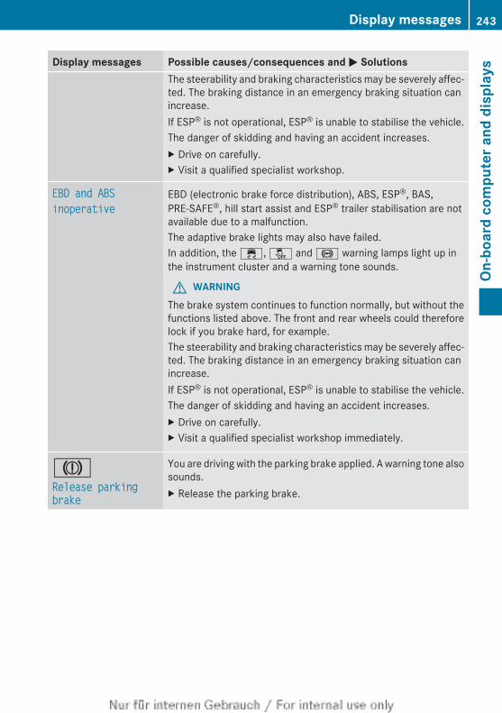
Display messages Possible causes/consequences and M SolutionsThe steerability and braking characteristics may be severely affec-ted. The braking distance in an emergency braking situation canincrease.If ESP® is not operational, ESP® is unable to stabilise the vehicle.The danger of skidding and having an accident increases.X Drive on carefully.X Visit a qualified specialist workshop.
EBD and ABSinoperative
EBD (electronic brake force distribution), ABS, ESP®, BAS,PRE-SAFE®, hill start assist and ESP® trailer stabilisation are notavailable due to a malfunction.The adaptive brake lights may also have failed.In addition, the ÷, å and ! warning lamps light up inthe instrument cluster and a warning tone sounds.
G WARNINGThe brake system continues to function normally, but without thefunctions listed above. The front and rear wheels could thereforelock if you brake hard, for example.The steerability and braking characteristics may be severely affec-ted. The braking distance in an emergency braking situation canincrease.If ESP® is not operational, ESP® is unable to stabilise the vehicle.The danger of skidding and having an accident increases.X Drive on carefully.X Visit a qualified specialist workshop immediately.
JRelease parking brake
You are driving with the parking brake applied. A warning tone alsosounds.X Release the parking brake.
Display messages 243
On-b
oard
com
pute
r and
dis
play
s
Z
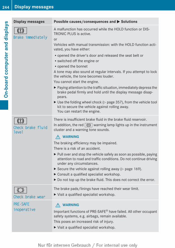
Display messages Possible causes/consequences and M Solutions
JBrake immediately
A malfunction has occurred while the HOLD function or DIS-TRONIC PLUS is active.orVehicles with manual transmission: with the HOLD function acti-vated, you have either:Ropened the driver's door and released the seat belt orRswitched off the engine orRopened the bonnetA tone may also sound at regular intervals. If you attempt to lockthe vehicle, the tone becomes louder.You cannot start the engine.X Paying attention to the traffic situation, immediately depress the
brake pedal firmly and hold until the display message disap-pears.
X Use the folding wheel chock (Y page 357), from the vehicle toolkit to secure the vehicle against rolling away.You can restart the engine.
JCheck brake fluid level
There is insufficient brake fluid in the brake fluid reservoir.In addition, the red J warning lamp lights up in the instrumentcluster and a warning tone sounds.
G WARNINGThe braking efficiency may be impaired.There is a risk of an accident.X Pull over and stop the vehicle safely as soon as possible, paying
attention to road and traffic conditions. Do not continue drivingunder any circumstances.
X Secure the vehicle against rolling away (Y page 169).X Consult a qualified specialist workshop.X Do not top up the brake fluid. This does not correct the error.
#Check brake wear
The brake pads/linings have reached their wear limit.X Visit a qualified specialist workshop.
PRE-SAFEinoperative
G WARNING
Important functions of PRE-SAFE® have failed. All other occupantsafety systems, e.g. airbags, remain available.This poses an increased risk of injury.X Visit a qualified specialist workshop.
244 Display messagesOn
-boa
rd c
ompu
ter a
nd d
ispl
ays
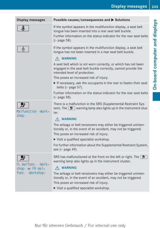
Display messages Possible causes/consequences and M Solutions
ü If the symbol appears in the multifunction display, a seat belttongue has been inserted into a rear seat belt buckle.Further information on the status indicator for the rear seat belts(Y page 58).
ý If the symbol appears in the multifunction display, a seat belttongue has not been inserted in a rear seat belt buckle.
G WARNINGA seat belt which is not worn correctly, or which has not beenengaged in the seat belt buckle correctly, cannot provide theintended level of protection.This poses an increased risk of injury.X If necessary, ask the occupants in the rear to fasten their seat
belts (Y page 57).Further information on the status indicator for the rear seat belts(Y page 58).
6Malfunction -Work‐shop-
There is a malfunction in the SRS (Supplemental Restraint Sys-tem). The 6 warning lamp also lights up in the instrument clus-ter.
G WARNINGThe airbags or belt tensioners may either be triggered uninten-tionally or, in the event of an accident, may not be triggered.This poses an increased risk of injury.X Visit a qualified specialist workshop.For further information about the Supplemental Restraint System,see (Y page 49).
6FL malfunc. -Work‐shop- or FR mal‐func. -Workshop-
SRS has malfunctioned at the front on the left or right. The 6warning lamp also lights up in the instrument cluster.
G WARNINGThe airbags or belt tensioners may either be triggered uninten-tionally or, in the event of an accident, may not be triggered.This poses an increased risk of injury.X Visit a qualified specialist workshop.
Display messages 245
On-b
oard
com
pute
r and
dis
play
s
Z
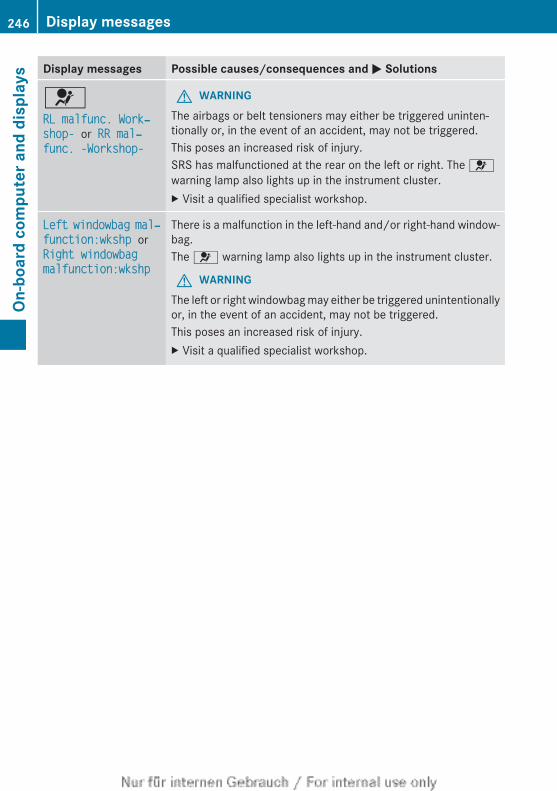
Display messages Possible causes/consequences and M Solutions
6RL malfunc. Work‐shop- or RR mal‐func. -Workshop-
G WARNINGThe airbags or belt tensioners may either be triggered uninten-tionally or, in the event of an accident, may not be triggered.This poses an increased risk of injury.SRS has malfunctioned at the rear on the left or right. The 6warning lamp also lights up in the instrument cluster.X Visit a qualified specialist workshop.
Left windowbag mal‐function:wkshp or Right windowbag malfunction:wkshp
There is a malfunction in the left-hand and/or right-hand window-bag.The 6 warning lamp also lights up in the instrument cluster.
G WARNINGThe left or right windowbag may either be triggered unintentionallyor, in the event of an accident, may not be triggered.This poses an increased risk of injury.X Visit a qualified specialist workshop.
246 Display messagesOn
-boa
rd c
ompu
ter a
nd d
ispl
ays
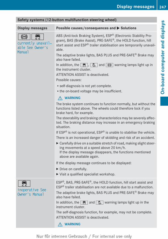
Safety systems (12-button multifunction steering wheel)
Display messages Possible causes/consequences and M Solutions
!÷currently unavail‐able See Owner's Manual
ABS (Anti-lock Braking System), ESP® (Electronic Stability Pro-gram), BAS (Brake Assist), PRE-SAFE®, the HOLD function, hillstart assist and ESP® trailer stabilisation are temporarily unavail-able.The adaptive brake lights, BAS PLUS and PRE-SAFE® Brake mayalso have failed.In addition, the ÷, å and ! warning lamps light up inthe instrument cluster.ATTENTION ASSIST is deactivated.Possible causes:Rself-diagnosis is not yet complete.Rthe on-board voltage may be insufficient.
G WARNINGThe brake system continues to function normally, but without thefunctions listed above. The wheels could therefore lock if youbrake hard, for example.The steerability and braking characteristics may be severely affec-ted. The braking distance may increase in an emergency brakingsituation.If ESP® is not operational, ESP® is unable to stabilise the vehicle.There is an increased danger of skidding and risk of an accident.X Carefully drive on a suitable stretch of road, making slight steer-
ing movements at a speed above 20 km/h.If the display message disappears, the functions mentionedabove are available again.
If the display message continues to be displayed:X Drive on carefully.X Visit a qualified specialist workshop.
÷inoperative See Owner's Manual
ESP®, BAS, PRE-SAFE®, the HOLD function, hill start assist andESP® trailer stabilisation are not available due to a malfunction.The adaptive brake lights, BAS PLUS and PRE-SAFE® Brake mayalso have failed.In addition, the ÷ and å warning lamps light up in theinstrument cluster.The self-diagnosis function, for example, may not be complete.ATTENTION ASSIST is deactivated.
G WARNING
Display messages 247
On-b
oard
com
pute
r and
dis
play
s
Z
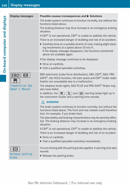
Display messages Possible causes/consequences and M SolutionsThe brake system continues to function normally, but without thefunctions listed above.The braking distance may thus increase in an emergency brakingsituation.If ESP® is not operational, ESP® is unable to stabilise the vehicle.There is an increased danger of skidding and risk of an accident.X Carefully drive on a suitable stretch of road, making slight steer-
ing movements at a speed above 20 km/h.If the display message disappears, the functions mentionedabove are available again.
If the display message continues to be displayed:X Drive on carefully.X Visit a qualified specialist workshop.
T!÷inoperative See Owner's Manual
EBD (electronic brake force distribution), ABS, ESP®, BAS, PRE-SAFE®, the HOLD function, hill start assist and ESP® trailer stabi-lisation are unavailable due to a malfunction.The adaptive brake lights, BAS PLUS and PRE-SAFE® Brake mayalso have failed.In addition, the ÷, å and ! warning lamps light up inthe instrument cluster and a warning tone sounds.
G WARNINGThe brake system continues to function normally, but without thefunctions listed above. The front and rear wheels could thereforelock, for example, if you brake hard.The steerability and braking characteristics may be severely affec-ted. The braking distance may increase in an emergency brakingsituation.If ESP® is not operational, ESP® is unable to stabilise the vehicle.There is an increased danger of skidding and risk of an accident.X Drive on carefully.X Visit a qualified specialist workshop immediately.
JRelease parking brake
You are driving with the parking brake applied. A warning tone alsosounds.X Release the parking brake.
248 Display messagesOn
-boa
rd c
ompu
ter a
nd d
ispl
ays
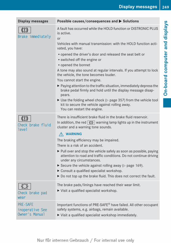
Display messages Possible causes/consequences and M Solutions
JBrake immediately
A fault has occurred while the HOLD function or DISTRONIC PLUSis active.orVehicles with manual transmission: with the HOLD function acti-vated, you have:Ropened the driver's door and released the seat belt orRswitched off the engine orRopened the bonnetA tone may also sound at regular intervals. If you attempt to lockthe vehicle, the tone becomes louder.You cannot start the engine.X Paying attention to the traffic situation, immediately depress the
brake pedal firmly and hold until the display message disap-pears.
X Use the folding wheel chock (Y page 357) from the vehicle toolkit to secure the vehicle against rolling away.You can restart the engine.
JCheck brake fluid level
There is insufficient brake fluid in the brake fluid reservoir.In addition, the red J warning lamp lights up in the instrumentcluster and a warning tone sounds.
G WARNINGThe braking efficiency may be impaired.There is a risk of an accident.X Pull over and stop the vehicle safely as soon as possible, paying
attention to road and traffic conditions. Do not continue drivingunder any circumstances.
X Secure the vehicle against rolling away (Y page 169).X Consult a qualified specialist workshop.X Do not top up the brake fluid. This does not correct the fault.
#Check brake pad wear
The brake pads/linings have reached their wear limit.X Visit a qualified specialist workshop.
PRE-SAFEinoperative See Owner's Manual
Important functions of PRE-SAFE® have failed. All other occupantsafety systems, e.g. airbags, remain available.X Visit a qualified specialist workshop immediately.
Display messages 249
On-b
oard
com
pute
r and
dis
play
s
Z
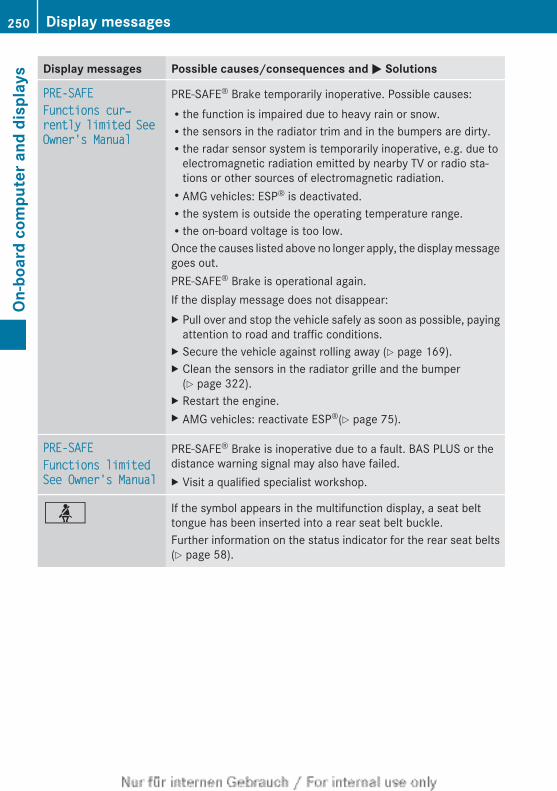
Display messages Possible causes/consequences and M Solutions
PRE-SAFEFunctions cur‐rently limited See Owner's Manual
PRE-SAFE® Brake temporarily inoperative. Possible causes:Rthe function is impaired due to heavy rain or snow.Rthe sensors in the radiator trim and in the bumpers are dirty.Rthe radar sensor system is temporarily inoperative, e.g. due to
electromagnetic radiation emitted by nearby TV or radio sta-tions or other sources of electromagnetic radiation.RAMG vehicles: ESP® is deactivated.Rthe system is outside the operating temperature range.Rthe on-board voltage is too low.Once the causes listed above no longer apply, the display messagegoes out.PRE-SAFE® Brake is operational again.If the display message does not disappear:X Pull over and stop the vehicle safely as soon as possible, paying
attention to road and traffic conditions.X Secure the vehicle against rolling away (Y page 169).X Clean the sensors in the radiator grille and the bumper
(Y page 322).X Restart the engine.X AMG vehicles: reactivate ESP®(Y page 75).
PRE-SAFEFunctions limited See Owner's Manual
PRE-SAFE® Brake is inoperative due to a fault. BAS PLUS or thedistance warning signal may also have failed.X Visit a qualified specialist workshop.
ü If the symbol appears in the multifunction display, a seat belttongue has been inserted into a rear seat belt buckle.Further information on the status indicator for the rear seat belts(Y page 58).
250 Display messagesOn
-boa
rd c
ompu
ter a
nd d
ispl
ays

Display messages Possible causes/consequences and M Solutions
ý If the symbol appears in the multifunction display, a seat belttongue has not been inserted in a rear seat belt buckle.
G WARNINGA seat belt which is not worn correctly, or which has not beenengaged in the seat belt buckle correctly, cannot provide theintended level of protection.This poses an increased risk of injury.X If necessary, ask the occupants in the rear to fasten their seat
belts (Y page 57).Further information on the status indicator for the rear seat belts(Y page 58).
6Restraint sys. mal‐function Consult workshop
There is a malfunction in the SRS (Supplemental Restraint Sys-tem). The 6 warning lamp also lights up in the instrument clus-ter.
G WARNINGThe airbags or belt tensioners may either be triggered uninten-tionally or, in the event of an accident, may not be triggered.This poses an increased risk of injury.X Visit a qualified specialist workshop.For further information about the Supplemental Restraint System;see (Y page 49).
6Front left malfunc‐tion Consult work‐shoporFront right malfunction Con‐sult workshop
SRS has malfunctioned at the front on the left or right. The 6warning lamp also lights up in the instrument cluster.
G WARNINGThe airbags or belt tensioners may either be triggered uninten-tionally or, in the event of an accident, may not be triggered.This poses an increased risk of injury.X Visit a qualified specialist workshop.
Display messages 251
On-b
oard
com
pute
r and
dis
play
s
Z
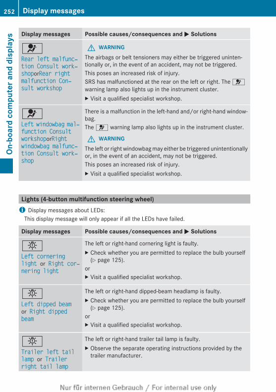
Display messages Possible causes/consequences and M Solutions
6Rear left malfunc‐tion Consult work‐shoporRear right malfunction Con‐sult workshop
G WARNINGThe airbags or belt tensioners may either be triggered uninten-tionally or, in the event of an accident, may not be triggered.This poses an increased risk of injury.SRS has malfunctioned at the rear on the left or right. The 6warning lamp also lights up in the instrument cluster.X Visit a qualified specialist workshop.
6Left windowbag mal‐function Consult workshoporRight windowbag malfunc‐tion Consult work‐shop
There is a malfunction in the left-hand and/or right-hand window-bag.The 6 warning lamp also lights up in the instrument cluster.
G WARNINGThe left or right windowbag may either be triggered unintentionallyor, in the event of an accident, may not be triggered.This poses an increased risk of injury.X Visit a qualified specialist workshop.
Lights (4-button multifunction steering wheel)i Display messages about LEDs:
This display message will only appear if all the LEDs have failed.
Display messages Possible causes/consequences and M Solutions
bLeft cornering light or Right cor‐nering light
The left or right-hand cornering light is faulty.X Check whether you are permitted to replace the bulb yourself
(Y page 125).orX Visit a qualified specialist workshop.
bLeft dipped beam or Right dipped beam
The left or right-hand dipped-beam headlamp is faulty.X Check whether you are permitted to replace the bulb yourself
(Y page 125).orX Visit a qualified specialist workshop.
bTrailer left tail lamp or Trailer right tail lamp
The left or right-hand trailer tail lamp is faulty.X Observe the separate operating instructions provided by the
trailer manufacturer.
252 Display messagesOn
-boa
rd c
ompu
ter a
nd d
ispl
ays
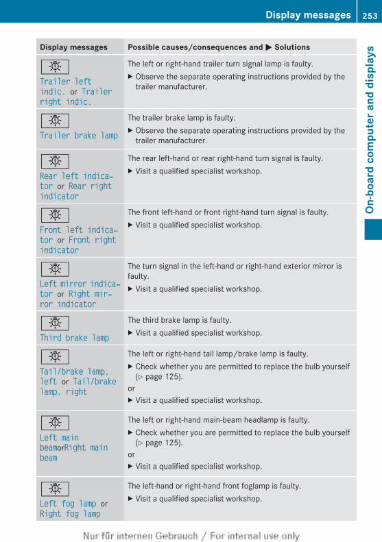
Display messages Possible causes/consequences and M Solutions
bTrailer left indic. or Trailer right indic.
The left or right-hand trailer turn signal lamp is faulty.X Observe the separate operating instructions provided by the
trailer manufacturer.
bTrailer brake lamp
The trailer brake lamp is faulty.X Observe the separate operating instructions provided by the
trailer manufacturer.
bRear left indica‐tor or Rear right indicator
The rear left-hand or rear right-hand turn signal is faulty.X Visit a qualified specialist workshop.
bFront left indica‐tor or Front right indicator
The front left-hand or front right-hand turn signal is faulty.X Visit a qualified specialist workshop.
bLeft mirror indica‐tor or Right mir‐ror indicator
The turn signal in the left-hand or right-hand exterior mirror isfaulty.X Visit a qualified specialist workshop.
bThird brake lamp
The third brake lamp is faulty.X Visit a qualified specialist workshop.
bTail/brake lamp, left or Tail/brake lamp, right
The left or right-hand tail lamp/brake lamp is faulty.X Check whether you are permitted to replace the bulb yourself
(Y page 125).orX Visit a qualified specialist workshop.
bLeft main beamorRight main beam
The left or right-hand main-beam headlamp is faulty.X Check whether you are permitted to replace the bulb yourself
(Y page 125).orX Visit a qualified specialist workshop.
bLeft fog lamp or Right fog lamp
The left-hand or right-hand front foglamp is faulty.X Visit a qualified specialist workshop.
Display messages 253
On-b
oard
com
pute
r and
dis
play
s
Z
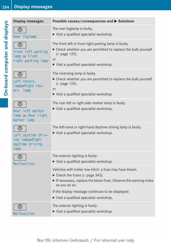
Display messages Possible causes/consequences and M Solutions
bRear foglamp
The rear foglamp is faulty.X Visit a qualified specialist workshop.
bFront left parking lamp or Front right parking lamp
The front left or front right parking lamp is faulty.X Check whether you are permitted to replace the bulb yourself
(Y page 125).orX Visit a qualified specialist workshop.
bLeft revers. lamporRight rev‐ers. lamp
The reversing lamp is faulty.X Check whether you are permitted to replace the bulb yourself
(Y page 125).orX Visit a qualified specialist workshop.
bRear left marker lamp or Rear right marker lamp
The rear left or right side marker lamp is faulty.X Visit a qualified specialist workshop.
bLeft daytime driv‐ing lamporRight daytime driving lamp
The left-hand or right-hand daytime driving lamp is faulty.X Visit a qualified specialist workshop.
bMalfunction
The exterior lighting is faulty.X Visit a qualified specialist workshop.
Vehicles with trailer tow hitch: a fuse may have blown.X Check the fuses (Y page 343).X If necessary, replace the blown fuse. Observe the warning notes
as you do so.
If the display message continues to be displayed:X Visit a qualified specialist workshop.
bMalfunction
The exterior lighting is faulty.X Visit a qualified specialist workshop.
254 Display messagesOn
-boa
rd c
ompu
ter a
nd d
ispl
ays
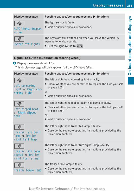
Display messages Possible causes/consequences and M Solutions
bAUTO lights inoper‐ative
The light sensor is faulty.X Visit a qualified specialist workshop.
bSwitch off lights
The lights are still switched on when you leave the vehicle. Awarning tone also sounds.X Turn the light switch to Ã.
Lights (12-button multifunction steering wheel)i Display messages about LEDs:
This display message will only appear if all the LEDs have failed.
Display messages Possible causes/consequences and M Solutions
bLeft cornering light or Right cor‐nering light
The left or right-hand cornering light is faulty.X Check whether you are permitted to replace the bulb yourself
(Y page 125).orX Visit a qualified specialist workshop.
bLeft dipped beam or Right dipped beam
The left or right-hand dipped-beam headlamp is faulty.X Check whether you are permitted to replace the bulb yourself
(Y page 125).orX Visit a qualified specialist workshop.
bTrailer left tail lamp or Trailer right tail lamp
The left or right-hand trailer tail lamp is faulty.X Observe the separate operating instructions provided by the
trailer manufacturer.
bTrailer left turn signal or Trailer right turn signal
The left or right-hand trailer turn signal lamp is faulty.X Observe the separate operating instructions provided by the
trailer manufacturer.
bTrailer brake lamp
The trailer brake lamp is faulty.X Observe the separate operating instructions provided by the
trailer manufacturer.
Display messages 255
On-b
oard
com
pute
r and
dis
play
s
Z
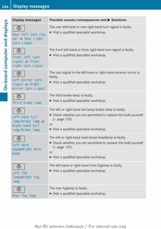
Display messages Possible causes/consequences and M Solutions
bRear left turn sig‐nal or Rear right turn signal
The rear left-hand or rear right-hand turn signal is faulty.X Visit a qualified specialist workshop.
bFront left turn signal or Front right turn signal
The front left-hand or front right-hand turn signal is faulty.X Visit a qualified specialist workshop.
bLeft mirror turn signal or Right mirror turn signal
The turn signal in the left-hand or right-hand exterior mirror isfaulty.X Visit a qualified specialist workshop.
bThird brake lamp
The third brake lamp is faulty.X Visit a qualified specialist workshop.
bLeft-hand tail lamp/brake lamp or Right-hand tail lamp/brake lamp
The left or right-hand tail lamp/brake lamp is faulty.X Check whether you are permitted to replace the bulb yourself
(Y page 125).orX Visit a qualified specialist workshop.
bLeft main beamorRight main beam
The left or right-hand main-beam headlamp is faulty.X Check whether you are permitted to replace the bulb yourself
(Y page 125).orX Visit a qualified specialist workshop.
bLeft fog lamporRight fog lamp
The left-hand or right-hand front foglamp is faulty.X Visit a qualified specialist workshop.
bRear fog lamp
The rear foglamp is faulty.X Visit a qualified specialist workshop.
256 Display messagesOn
-boa
rd c
ompu
ter a
nd d
ispl
ays
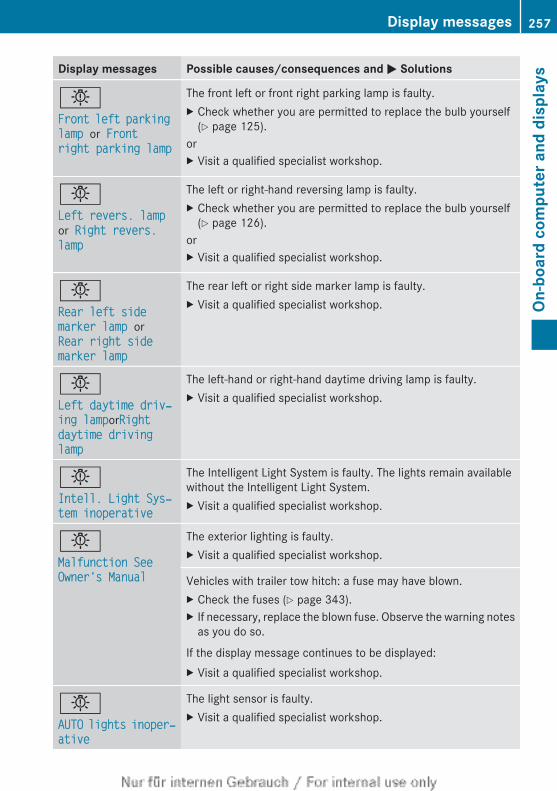
Display messages Possible causes/consequences and M Solutions
bFront left parking lamp or Front right parking lamp
The front left or front right parking lamp is faulty.X Check whether you are permitted to replace the bulb yourself
(Y page 125).orX Visit a qualified specialist workshop.
bLeft revers. lamp or Right revers. lamp
The left or right-hand reversing lamp is faulty.X Check whether you are permitted to replace the bulb yourself
(Y page 126).orX Visit a qualified specialist workshop.
bRear left side marker lamp or Rear right side marker lamp
The rear left or right side marker lamp is faulty.X Visit a qualified specialist workshop.
bLeft daytime driv‐ing lamporRight daytime driving lamp
The left-hand or right-hand daytime driving lamp is faulty.X Visit a qualified specialist workshop.
bIntell. Light Sys‐tem inoperative
The Intelligent Light System is faulty. The lights remain availablewithout the Intelligent Light System.X Visit a qualified specialist workshop.
bMalfunction See Owner's Manual
The exterior lighting is faulty.X Visit a qualified specialist workshop.
Vehicles with trailer tow hitch: a fuse may have blown.X Check the fuses (Y page 343).X If necessary, replace the blown fuse. Observe the warning notes
as you do so.
If the display message continues to be displayed:X Visit a qualified specialist workshop.
bAUTO lights inoper‐ative
The light sensor is faulty.X Visit a qualified specialist workshop.
Display messages 257
On-b
oard
com
pute
r and
dis
play
s
Z
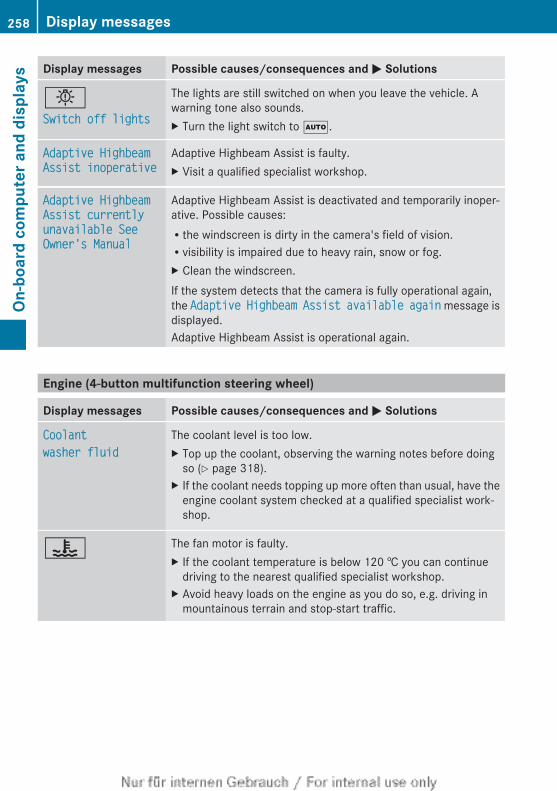
Display messages Possible causes/consequences and M Solutions
bSwitch off lights
The lights are still switched on when you leave the vehicle. Awarning tone also sounds.X Turn the light switch to Ã.
Adaptive Highbeam Assist inoperative
Adaptive Highbeam Assist is faulty.X Visit a qualified specialist workshop.
Adaptive Highbeam Assist currently unavailable See Owner's Manual
Adaptive Highbeam Assist is deactivated and temporarily inoper-ative. Possible causes:Rthe windscreen is dirty in the camera's field of vision.Rvisibility is impaired due to heavy rain, snow or fog.X Clean the windscreen.If the system detects that the camera is fully operational again,the Adaptive Highbeam Assist available again message isdisplayed.Adaptive Highbeam Assist is operational again.
Engine (4-button multifunction steering wheel)
Display messages Possible causes/consequences and M Solutions
Coolantwasher fluid
The coolant level is too low.X Top up the coolant, observing the warning notes before doing
so (Y page 318).X If the coolant needs topping up more often than usual, have the
engine coolant system checked at a qualified specialist work-shop.
? The fan motor is faulty.X If the coolant temperature is below 120 † you can continue
driving to the nearest qualified specialist workshop.X Avoid heavy loads on the engine as you do so, e.g. driving in
mountainous terrain and stop-start traffic.
258 Display messagesOn
-boa
rd c
ompu
ter a
nd d
ispl
ays
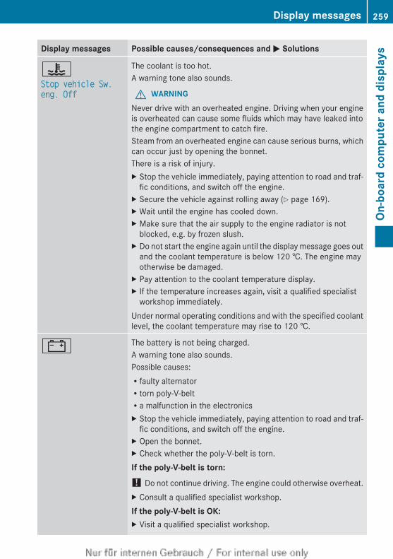
Display messages Possible causes/consequences and M Solutions
?Stop vehicle Sw. eng. Off
The coolant is too hot.A warning tone also sounds.
G WARNINGNever drive with an overheated engine. Driving when your engineis overheated can cause some fluids which may have leaked intothe engine compartment to catch fire.Steam from an overheated engine can cause serious burns, whichcan occur just by opening the bonnet.There is a risk of injury.X Stop the vehicle immediately, paying attention to road and traf-
fic conditions, and switch off the engine.X Secure the vehicle against rolling away (Y page 169).X Wait until the engine has cooled down.X Make sure that the air supply to the engine radiator is not
blocked, e.g. by frozen slush.X Do not start the engine again until the display message goes out
and the coolant temperature is below 120 †. The engine mayotherwise be damaged.
X Pay attention to the coolant temperature display.X If the temperature increases again, visit a qualified specialist
workshop immediately.Under normal operating conditions and with the specified coolantlevel, the coolant temperature may rise to 120 †.
# The battery is not being charged.A warning tone also sounds.Possible causes:Rfaulty alternatorRtorn poly-V-beltRa malfunction in the electronicsX Stop the vehicle immediately, paying attention to road and traf-
fic conditions, and switch off the engine.X Open the bonnet.X Check whether the poly-V-belt is torn.If the poly-V-belt is torn:! Do not continue driving. The engine could otherwise overheat.X Consult a qualified specialist workshop.If the poly-V-belt is OK:X Visit a qualified specialist workshop.
Display messages 259
On-b
oard
com
pute
r and
dis
play
s
Z
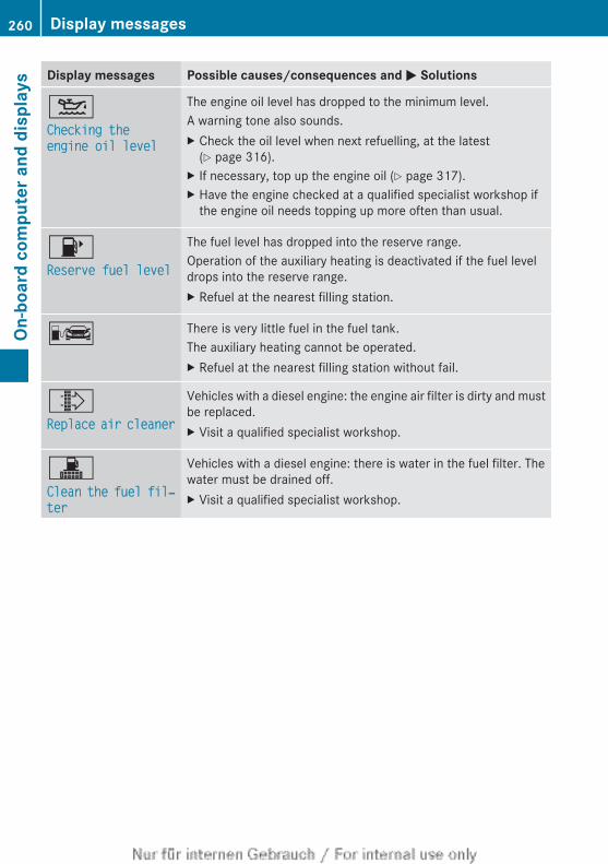
Display messages Possible causes/consequences and M Solutions
4Checking the engine oil level
The engine oil level has dropped to the minimum level.A warning tone also sounds.X Check the oil level when next refuelling, at the latest
(Y page 316).X If necessary, top up the engine oil (Y page 317).X Have the engine checked at a qualified specialist workshop if
the engine oil needs topping up more often than usual.
8Reserve fuel level
The fuel level has dropped into the reserve range.Operation of the auxiliary heating is deactivated if the fuel leveldrops into the reserve range.X Refuel at the nearest filling station.
C There is very little fuel in the fuel tank.The auxiliary heating cannot be operated.X Refuel at the nearest filling station without fail.
¸Replace air cleaner
Vehicles with a diesel engine: the engine air filter is dirty and mustbe replaced.X Visit a qualified specialist workshop.
!Clean the fuel fil‐ter
Vehicles with a diesel engine: there is water in the fuel filter. Thewater must be drained off.X Visit a qualified specialist workshop.
260 Display messagesOn
-boa
rd c
ompu
ter a
nd d
ispl
ays
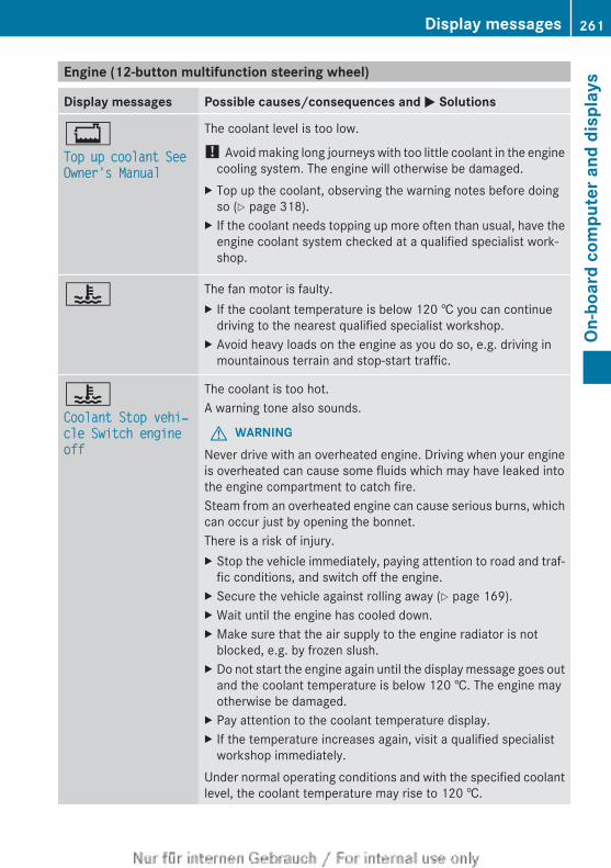
Engine (12-button multifunction steering wheel)
Display messages Possible causes/consequences and M Solutions
+Top up coolant See Owner's Manual
The coolant level is too low.
! Avoid making long journeys with too little coolant in the enginecooling system. The engine will otherwise be damaged.
X Top up the coolant, observing the warning notes before doingso (Y page 318).
X If the coolant needs topping up more often than usual, have theengine coolant system checked at a qualified specialist work-shop.
? The fan motor is faulty.X If the coolant temperature is below 120 † you can continue
driving to the nearest qualified specialist workshop.X Avoid heavy loads on the engine as you do so, e.g. driving in
mountainous terrain and stop-start traffic.
?Coolant Stop vehi‐cle Switch engine off
The coolant is too hot.A warning tone also sounds.
G WARNINGNever drive with an overheated engine. Driving when your engineis overheated can cause some fluids which may have leaked intothe engine compartment to catch fire.Steam from an overheated engine can cause serious burns, whichcan occur just by opening the bonnet.There is a risk of injury.X Stop the vehicle immediately, paying attention to road and traf-
fic conditions, and switch off the engine.X Secure the vehicle against rolling away (Y page 169).X Wait until the engine has cooled down.X Make sure that the air supply to the engine radiator is not
blocked, e.g. by frozen slush.X Do not start the engine again until the display message goes out
and the coolant temperature is below 120 †. The engine mayotherwise be damaged.
X Pay attention to the coolant temperature display.X If the temperature increases again, visit a qualified specialist
workshop immediately.Under normal operating conditions and with the specified coolantlevel, the coolant temperature may rise to 120 †.
Display messages 261
On-b
oard
com
pute
r and
dis
play
s
Z
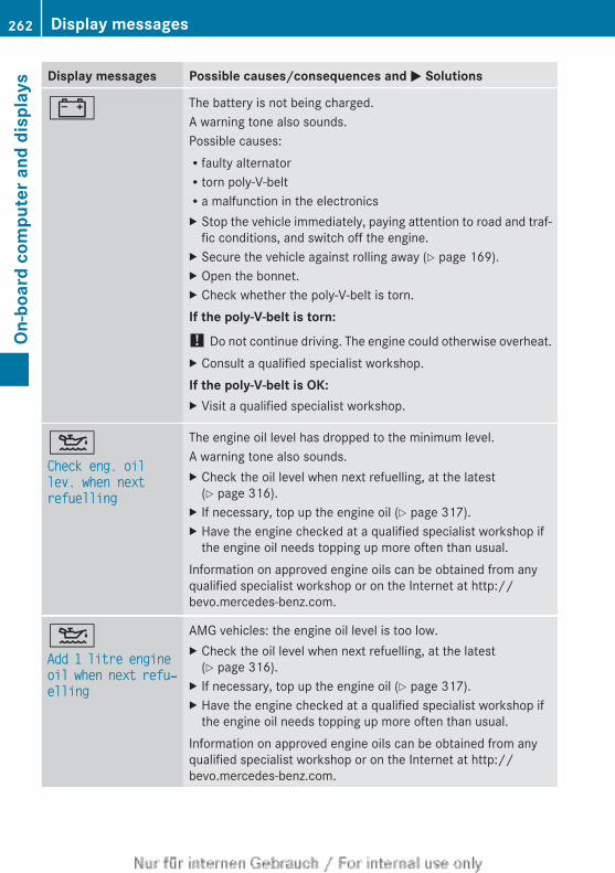
Display messages Possible causes/consequences and M Solutions
# The battery is not being charged.A warning tone also sounds.Possible causes:Rfaulty alternatorRtorn poly-V-beltRa malfunction in the electronicsX Stop the vehicle immediately, paying attention to road and traf-
fic conditions, and switch off the engine.X Secure the vehicle against rolling away (Y page 169).X Open the bonnet.X Check whether the poly-V-belt is torn.If the poly-V-belt is torn:! Do not continue driving. The engine could otherwise overheat.X Consult a qualified specialist workshop.If the poly-V-belt is OK:X Visit a qualified specialist workshop.
4Check eng. oil lev. when next refuelling
The engine oil level has dropped to the minimum level.A warning tone also sounds.X Check the oil level when next refuelling, at the latest
(Y page 316).X If necessary, top up the engine oil (Y page 317).X Have the engine checked at a qualified specialist workshop if
the engine oil needs topping up more often than usual.Information on approved engine oils can be obtained from anyqualified specialist workshop or on the Internet at http://bevo.mercedes-benz.com.
4Add 1 litre engine oil when next refu‐elling
AMG vehicles: the engine oil level is too low.X Check the oil level when next refuelling, at the latest
(Y page 316).X If necessary, top up the engine oil (Y page 317).X Have the engine checked at a qualified specialist workshop if
the engine oil needs topping up more often than usual.Information on approved engine oils can be obtained from anyqualified specialist workshop or on the Internet at http://bevo.mercedes-benz.com.
262 Display messagesOn
-boa
rd c
ompu
ter a
nd d
ispl
ays
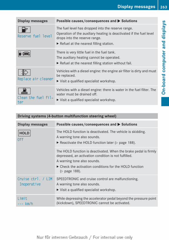
Display messages Possible causes/consequences and M Solutions
8Reserve fuel level
The fuel level has dropped into the reserve range.Operation of the auxiliary heating is deactivated if the fuel leveldrops into the reserve range.X Refuel at the nearest filling station.
C There is very little fuel in the fuel tank.The auxiliary heating cannot be operated.X Refuel at the nearest filling station without fail.
¸Replace air cleaner
Vehicles with a diesel engine: the engine air filter is dirty and mustbe replaced.X Visit a qualified specialist workshop.
!Clean the fuel fil‐ter
Vehicles with a diesel engine: there is water in the fuel filter. Thewater must be drained off.X Visit a qualified specialist workshop.
Driving systems (4-button multifunction steering wheel)
Display messages Possible causes/consequences and M Solutions
ëOff
The HOLD function is deactivated. The vehicle is skidding.A warning tone also sounds.X Reactivate the HOLD function later (Y page 188).
The HOLD function is deactivated. When the brake pedal is firmlydepressed, an activation condition is not fulfilled.A warning tone also sounds.X Check the activation conditions for the HOLD function
(Y page 188).
Cruise ctrl. / LIM Inoperative
SPEEDTRONIC and cruise control are malfunctioning.A warning tone also sounds.X Visit a qualified specialist workshop.
Limit--- km/h
While depressing the accelerator pedal beyond the pressure point(kickdown), SPEEDTRONIC cannot be activated.
Display messages 263
On-b
oard
com
pute
r and
dis
play
s
Z
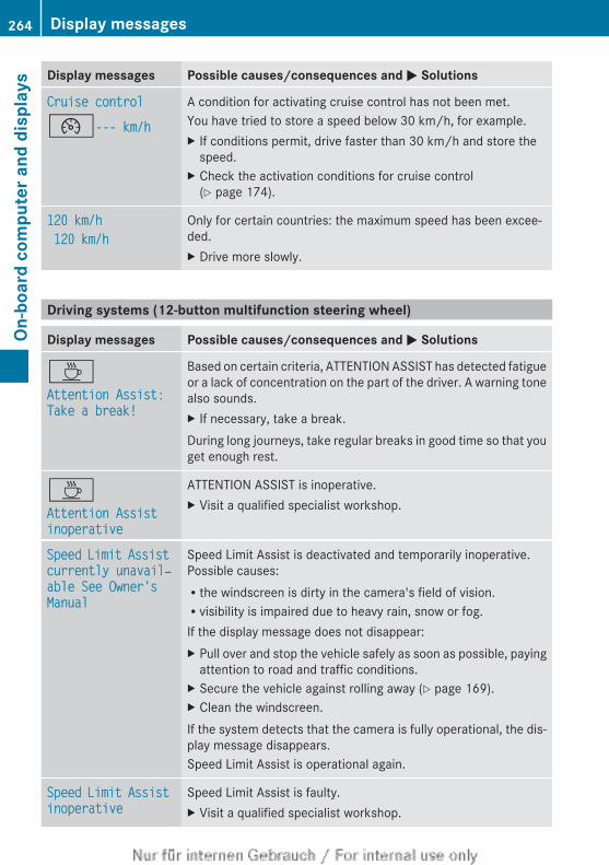
Display messages Possible causes/consequences and M Solutions
Cruise control¯--- km/h
A condition for activating cruise control has not been met.You have tried to store a speed below 30 km/h, for example.X If conditions permit, drive faster than 30 km/h and store the
speed.X Check the activation conditions for cruise control
(Y page 174).
120 km/h 120 km/h
Only for certain countries: the maximum speed has been excee-ded.X Drive more slowly.
Driving systems (12-button multifunction steering wheel)
Display messages Possible causes/consequences and M Solutions
ÀAttention Assist: Take a break!
Based on certain criteria, ATTENTION ASSIST has detected fatigueor a lack of concentration on the part of the driver. A warning tonealso sounds.X If necessary, take a break.During long journeys, take regular breaks in good time so that youget enough rest.
ÀAttention Assist inoperative
ATTENTION ASSIST is inoperative.X Visit a qualified specialist workshop.
Speed Limit Assist currently unavail‐able See Owner's Manual
Speed Limit Assist is deactivated and temporarily inoperative.Possible causes:Rthe windscreen is dirty in the camera's field of vision.Rvisibility is impaired due to heavy rain, snow or fog.If the display message does not disappear:X Pull over and stop the vehicle safely as soon as possible, paying
attention to road and traffic conditions.X Secure the vehicle against rolling away (Y page 169).X Clean the windscreen.If the system detects that the camera is fully operational, the dis-play message disappears.Speed Limit Assist is operational again.
Speed Limit Assist inoperative
Speed Limit Assist is faulty.X Visit a qualified specialist workshop.
264 Display messagesOn
-boa
rd c
ompu
ter a
nd d
ispl
ays
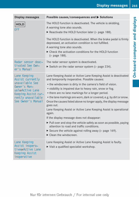
Display messages Possible causes/consequences and M Solutions
ëOff
The HOLD function is deactivated. The vehicle is skidding.A warning tone also sounds.X Reactivate the HOLD function later (Y page 188).
The HOLD function is deactivated. When the brake pedal is firmlydepressed, an activation condition is not fulfilled.A warning tone also sounds.X Check the activation conditions for the HOLD function
(Y page 188).
Radar sensor deac‐tivated See Own‐er's Manual
The radar sensor system is deactivated.X Switch on the radar sensor system (Y page 234).
Lane Keeping Assist currently unavailable See Owner's Man‐ualorActive Lane Keeping Assist cur‐rently unavailable See Owner's Manual
Lane Keeping Assist or Active Lane Keeping Assist is deactivatedand temporarily inoperative. Possible causes:Rthe windscreen is dirty in the camera's field of vision.Rvisibility is impaired due to heavy rain, snow or fog.Rthere are no lane markings for a longer period.Rthe lane markings are worn, dark or covered, e.g. by dirt or snow.Once the causes listed above no longer apply, the display messagegoes out.Lane Keeping Assist or Active Lane Keeping Assist is operationalagain.If the display message does not disappear:X Pull over and stop the vehicle safely as soon as possible, paying
attention to road and traffic conditions.X Secure the vehicle against rolling away (Y page 169).X Clean the windscreen.
Lane Keeping Assist inopera‐tiveorActive Lane Keeping Assist inoperative
Lane Keeping Assist or Active Lane Keeping Assist is faulty.X Visit a qualified specialist workshop.
Display messages 265
On-b
oard
com
pute
r and
dis
play
s
Z
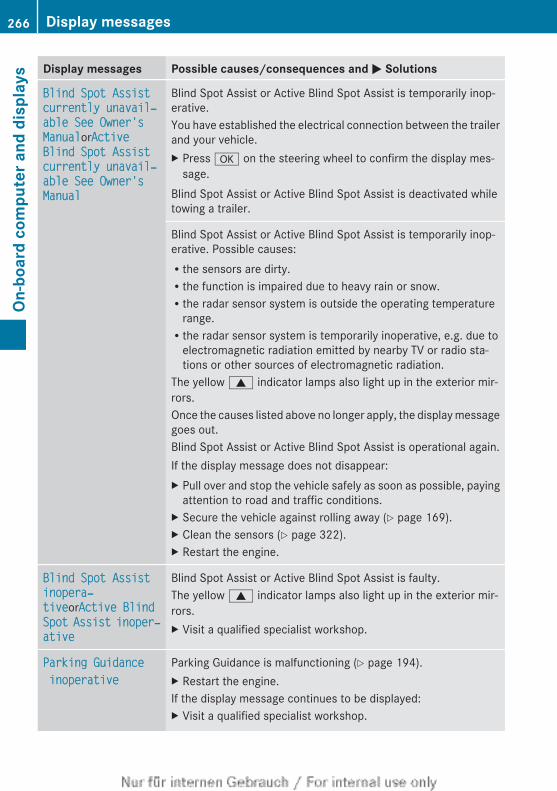
Display messages Possible causes/consequences and M Solutions
Blind Spot Assist currently unavail‐able See Owner's ManualorActive Blind Spot Assist currently unavail‐able See Owner's Manual
Blind Spot Assist or Active Blind Spot Assist is temporarily inop-erative.You have established the electrical connection between the trailerand your vehicle.X Press a on the steering wheel to confirm the display mes-
sage.Blind Spot Assist or Active Blind Spot Assist is deactivated whiletowing a trailer.
Blind Spot Assist or Active Blind Spot Assist is temporarily inop-erative. Possible causes:Rthe sensors are dirty.Rthe function is impaired due to heavy rain or snow.Rthe radar sensor system is outside the operating temperature
range.Rthe radar sensor system is temporarily inoperative, e.g. due to
electromagnetic radiation emitted by nearby TV or radio sta-tions or other sources of electromagnetic radiation.
The yellow 9 indicator lamps also light up in the exterior mir-rors.Once the causes listed above no longer apply, the display messagegoes out.Blind Spot Assist or Active Blind Spot Assist is operational again.If the display message does not disappear:X Pull over and stop the vehicle safely as soon as possible, paying
attention to road and traffic conditions.X Secure the vehicle against rolling away (Y page 169).X Clean the sensors (Y page 322).X Restart the engine.
Blind Spot Assist inopera‐tiveorActive Blind Spot Assist inoper‐ative
Blind Spot Assist or Active Blind Spot Assist is faulty.The yellow 9 indicator lamps also light up in the exterior mir-rors.X Visit a qualified specialist workshop.
Parking Guidance inoperative
Parking Guidance is malfunctioning (Y page 194).X Restart the engine.If the display message continues to be displayed:X Visit a qualified specialist workshop.
266 Display messagesOn
-boa
rd c
ompu
ter a
nd d
ispl
ays
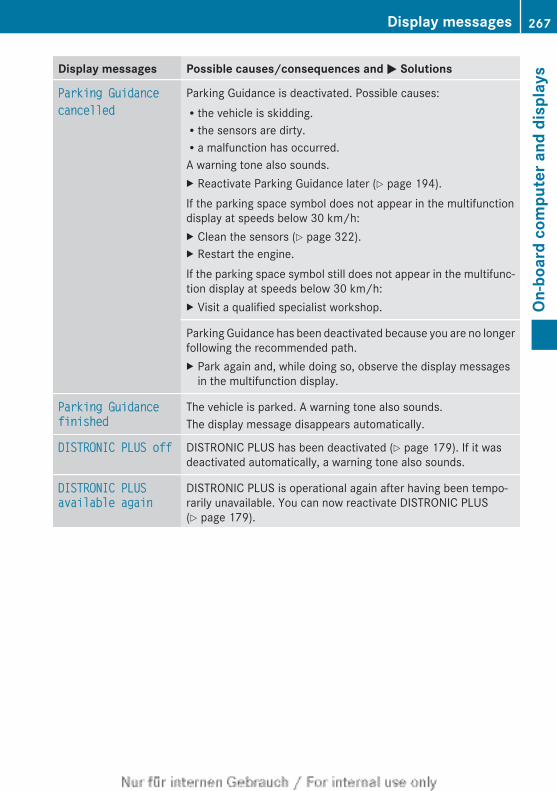
Display messages Possible causes/consequences and M Solutions
Parking Guidancecancelled
Parking Guidance is deactivated. Possible causes:Rthe vehicle is skidding.Rthe sensors are dirty.Ra malfunction has occurred.A warning tone also sounds.X Reactivate Parking Guidance later (Y page 194).If the parking space symbol does not appear in the multifunctiondisplay at speeds below 30 km/h:X Clean the sensors (Y page 322).X Restart the engine.If the parking space symbol still does not appear in the multifunc-tion display at speeds below 30 km/h:X Visit a qualified specialist workshop.
Parking Guidance has been deactivated because you are no longerfollowing the recommended path.X Park again and, while doing so, observe the display messages
in the multifunction display.
Parking Guidance finished
The vehicle is parked. A warning tone also sounds.The display message disappears automatically.
DISTRONIC PLUS off DISTRONIC PLUS has been deactivated (Y page 179). If it wasdeactivated automatically, a warning tone also sounds.
DISTRONIC PLUS available again
DISTRONIC PLUS is operational again after having been tempo-rarily unavailable. You can now reactivate DISTRONIC PLUS(Y page 179).
Display messages 267
On-b
oard
com
pute
r and
dis
play
s
Z
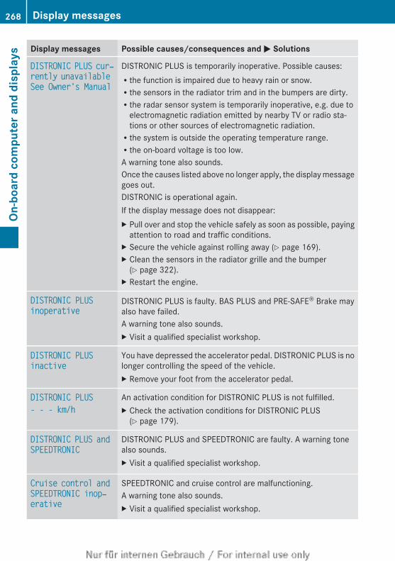
Display messages Possible causes/consequences and M Solutions
DISTRONIC PLUS cur‐rently unavailable See Owner's Manual
DISTRONIC PLUS is temporarily inoperative. Possible causes:Rthe function is impaired due to heavy rain or snow.Rthe sensors in the radiator trim and in the bumpers are dirty.Rthe radar sensor system is temporarily inoperative, e.g. due to
electromagnetic radiation emitted by nearby TV or radio sta-tions or other sources of electromagnetic radiation.Rthe system is outside the operating temperature range.Rthe on-board voltage is too low.A warning tone also sounds.Once the causes listed above no longer apply, the display messagegoes out.DISTRONIC is operational again.If the display message does not disappear:X Pull over and stop the vehicle safely as soon as possible, paying
attention to road and traffic conditions.X Secure the vehicle against rolling away (Y page 169).X Clean the sensors in the radiator grille and the bumper
(Y page 322).X Restart the engine.
DISTRONIC PLUS inoperative
DISTRONIC PLUS is faulty. BAS PLUS and PRE-SAFE® Brake mayalso have failed.A warning tone also sounds.X Visit a qualified specialist workshop.
DISTRONIC PLUS inactive
You have depressed the accelerator pedal. DISTRONIC PLUS is nolonger controlling the speed of the vehicle.X Remove your foot from the accelerator pedal.
DISTRONIC PLUS- - - km/h
An activation condition for DISTRONIC PLUS is not fulfilled.X Check the activation conditions for DISTRONIC PLUS
(Y page 179).
DISTRONIC PLUS and SPEEDTRONIC
DISTRONIC PLUS and SPEEDTRONIC are faulty. A warning tonealso sounds.X Visit a qualified specialist workshop.
Cruise control and SPEEDTRONIC inop‐erative
SPEEDTRONIC and cruise control are malfunctioning.A warning tone also sounds.X Visit a qualified specialist workshop.
268 Display messagesOn
-boa
rd c
ompu
ter a
nd d
ispl
ays
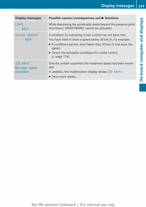
Display messages Possible causes/consequences and M Solutions
Limit--- km/h
While depressing the accelerator pedal beyond the pressure point(kickdown), SPEEDTRONIC cannot be activated.
Cruise control- - - km/h
A condition for activating cruise control has not been met.You have tried to store a speed below 30 km/h, for example.X If conditions permit, drive faster than 30 km/h and store the
speed.X Check the activation conditions for cruise control
(Y page 174).
120 km/h!Maximum speed exceeded
Only for certain countries: the maximum speed has been excee-ded.In addition, the multifunction display shows 120 km/h!.X Drive more slowly.
Display messages 269
On-b
oard
com
pute
r and
dis
play
s
Z
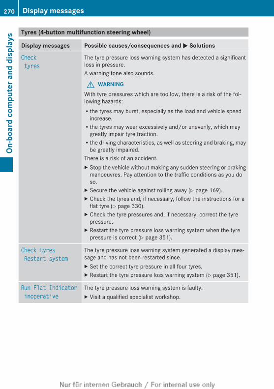
Tyres (4-button multifunction steering wheel)
Display messages Possible causes/consequences and M Solutions
Check tyres
The tyre pressure loss warning system has detected a significantloss in pressure.A warning tone also sounds.
G WARNINGWith tyre pressures which are too low, there is a risk of the fol-lowing hazards:Rthe tyres may burst, especially as the load and vehicle speed
increase.Rthe tyres may wear excessively and/or unevenly, which may
greatly impair tyre traction.Rthe driving characteristics, as well as steering and braking, may
be greatly impaired.There is a risk of an accident.X Stop the vehicle without making any sudden steering or braking
manoeuvres. Pay attention to the traffic conditions as you doso.
X Secure the vehicle against rolling away (Y page 169).X Check the tyres and, if necessary, follow the instructions for a
flat tyre (Y page 330).X Check the tyre pressures and, if necessary, correct the tyre
pressure.X Restart the tyre pressure loss warning system when the tyre
pressure is correct (Y page 351).
Check tyres Restart system
The tyre pressure loss warning system generated a display mes-sage and has not been restarted since.X Set the correct tyre pressure in all four tyres.X Restart the tyre pressure loss warning system (Y page 351).
Run Flat Indicator inoperative
The tyre pressure loss warning system is faulty.X Visit a qualified specialist workshop.
270 Display messagesOn
-boa
rd c
ompu
ter a
nd d
ispl
ays
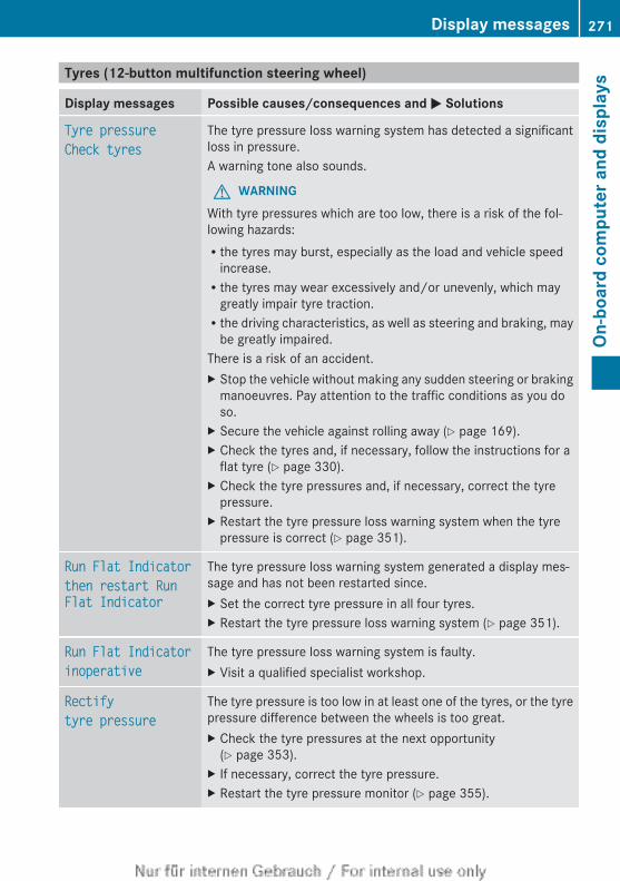
Tyres (12-button multifunction steering wheel)
Display messages Possible causes/consequences and M Solutions
Tyre pressureCheck tyres
The tyre pressure loss warning system has detected a significantloss in pressure.A warning tone also sounds.
G WARNINGWith tyre pressures which are too low, there is a risk of the fol-lowing hazards:Rthe tyres may burst, especially as the load and vehicle speed
increase.Rthe tyres may wear excessively and/or unevenly, which may
greatly impair tyre traction.Rthe driving characteristics, as well as steering and braking, may
be greatly impaired.There is a risk of an accident.X Stop the vehicle without making any sudden steering or braking
manoeuvres. Pay attention to the traffic conditions as you doso.
X Secure the vehicle against rolling away (Y page 169).X Check the tyres and, if necessary, follow the instructions for a
flat tyre (Y page 330).X Check the tyre pressures and, if necessary, correct the tyre
pressure.X Restart the tyre pressure loss warning system when the tyre
pressure is correct (Y page 351).
Run Flat Indicatorthen restart Run Flat Indicator
The tyre pressure loss warning system generated a display mes-sage and has not been restarted since.X Set the correct tyre pressure in all four tyres.X Restart the tyre pressure loss warning system (Y page 351).
Run Flat Indicatorinoperative
The tyre pressure loss warning system is faulty.X Visit a qualified specialist workshop.
Rectifytyre pressure
The tyre pressure is too low in at least one of the tyres, or the tyrepressure difference between the wheels is too great.X Check the tyre pressures at the next opportunity
(Y page 353).X If necessary, correct the tyre pressure.X Restart the tyre pressure monitor (Y page 355).
Display messages 271
On-b
oard
com
pute
r and
dis
play
s
Z
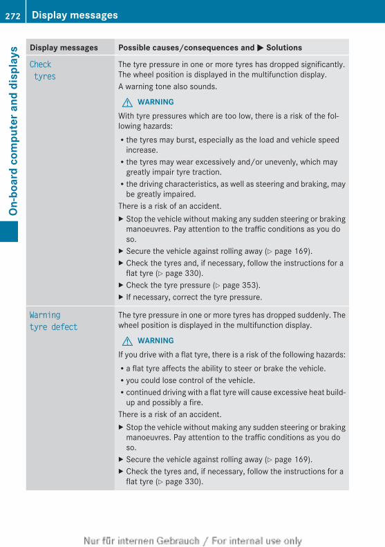
Display messages Possible causes/consequences and M Solutions
Check tyres
The tyre pressure in one or more tyres has dropped significantly.The wheel position is displayed in the multifunction display.A warning tone also sounds.
G WARNINGWith tyre pressures which are too low, there is a risk of the fol-lowing hazards:Rthe tyres may burst, especially as the load and vehicle speed
increase.Rthe tyres may wear excessively and/or unevenly, which may
greatly impair tyre traction.Rthe driving characteristics, as well as steering and braking, may
be greatly impaired.There is a risk of an accident.X Stop the vehicle without making any sudden steering or braking
manoeuvres. Pay attention to the traffic conditions as you doso.
X Secure the vehicle against rolling away (Y page 169).X Check the tyres and, if necessary, follow the instructions for a
flat tyre (Y page 330).X Check the tyre pressure (Y page 353).X If necessary, correct the tyre pressure.
Warningtyre defect
The tyre pressure in one or more tyres has dropped suddenly. Thewheel position is displayed in the multifunction display.
G WARNINGIf you drive with a flat tyre, there is a risk of the following hazards:Ra flat tyre affects the ability to steer or brake the vehicle.Ryou could lose control of the vehicle.Rcontinued driving with a flat tyre will cause excessive heat build-
up and possibly a fire.There is a risk of an accident.X Stop the vehicle without making any sudden steering or braking
manoeuvres. Pay attention to the traffic conditions as you doso.
X Secure the vehicle against rolling away (Y page 169).X Check the tyres and, if necessary, follow the instructions for a
flat tyre (Y page 330).
272 Display messagesOn
-boa
rd c
ompu
ter a
nd d
ispl
ays
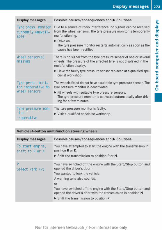
Display messages Possible causes/consequences and M Solutions
Tyre press. monitorcurrently unavail‐able
Due to a source of radio interference, no signals can be receivedfrom the wheel sensors. The tyre pressure monitor is temporarilymalfunctioning.X Drive on.
The tyre pressure monitor restarts automatically as soon as thecause has been rectified.
Wheel sensor(s) missing
There is no signal from the tyre pressure sensor of one or severalwheels. The pressure of the affected tyre is not displayed in themultifunction display.X Have the faulty tyre pressure sensor replaced at a qualified spe-
cialist workshop.
Tyre press. moni‐tor inoperative No wheel sensors
The wheels fitted do not have a suitable tyre pressure sensor. Thetyre pressure monitor is deactivated.X Fit wheels with suitable tyre pressure sensors.
The tyre pressure monitor is activated automatically after driv-ing for a few minutes.
Tyre pressure mon‐itorinoperative
The tyre pressure monitor is faulty.X Visit a qualified specialist workshop.
Vehicle (4-button multifunction steering wheel)
Display messages Possible causes/consequences and M Solutions
To start engine,shift to P or N
You have attempted to start the engine with the transmission inposition R or D.X Shift the transmission to position P or N.
PSelect Park (P)
You have switched off the engine with the Start/Stop button andopened the driver's door.You wanted to lock the vehicle.A warning tone also sounds.orYou have switched off the engine with the Start/Stop button andopened the driver's door with the transmission in position N.X Shift the transmission to position P.
Display messages 273
On-b
oard
com
pute
r and
dis
play
s
Z
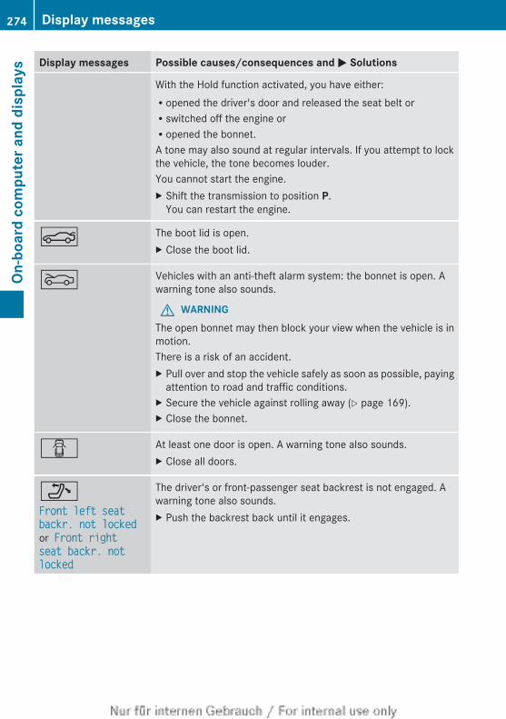
Display messages Possible causes/consequences and M Solutions
With the Hold function activated, you have either:Ropened the driver's door and released the seat belt orRswitched off the engine orRopened the bonnet.A tone may also sound at regular intervals. If you attempt to lockthe vehicle, the tone becomes louder.You cannot start the engine.X Shift the transmission to position P.
You can restart the engine.
N The boot lid is open.X Close the boot lid.
M Vehicles with an anti-theft alarm system: the bonnet is open. Awarning tone also sounds.
G WARNINGThe open bonnet may then block your view when the vehicle is inmotion.There is a risk of an accident.X Pull over and stop the vehicle safely as soon as possible, paying
attention to road and traffic conditions.X Secure the vehicle against rolling away (Y page 169).X Close the bonnet.
C At least one door is open. A warning tone also sounds.X Close all doors.
_Front left seat backr. not locked or Front right seat backr. not locked
The driver's or front-passenger seat backrest is not engaged. Awarning tone also sounds.X Push the backrest back until it engages.
274 Display messagesOn
-boa
rd c
ompu
ter a
nd d
ispl
ays
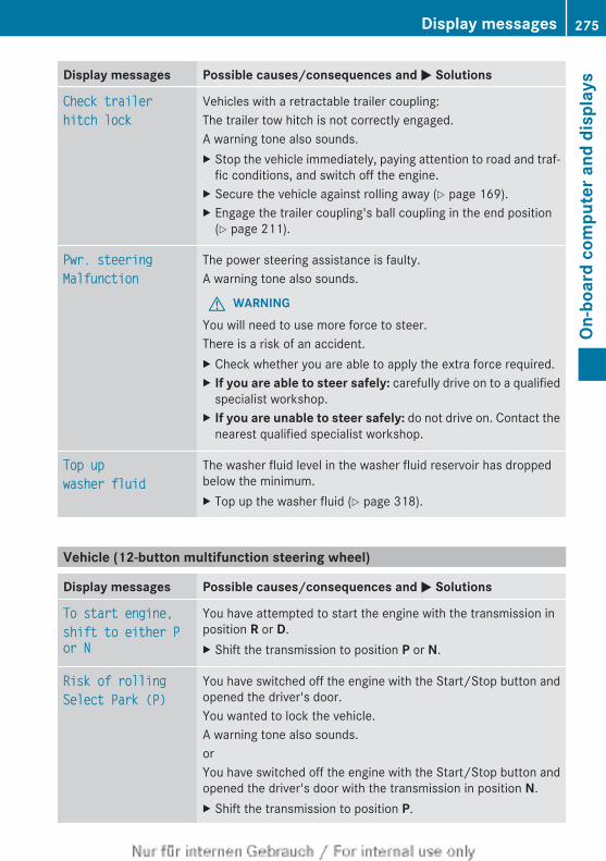
Display messages Possible causes/consequences and M Solutions
Check trailerhitch lock
Vehicles with a retractable trailer coupling:The trailer tow hitch is not correctly engaged.A warning tone also sounds.X Stop the vehicle immediately, paying attention to road and traf-
fic conditions, and switch off the engine.X Secure the vehicle against rolling away (Y page 169).X Engage the trailer coupling's ball coupling in the end position
(Y page 211).
Pwr. steering Malfunction
The power steering assistance is faulty.A warning tone also sounds.
G WARNINGYou will need to use more force to steer.There is a risk of an accident.X Check whether you are able to apply the extra force required.X If you are able to steer safely: carefully drive on to a qualified
specialist workshop.X If you are unable to steer safely: do not drive on. Contact the
nearest qualified specialist workshop.
Top up washer fluid
The washer fluid level in the washer fluid reservoir has droppedbelow the minimum.X Top up the washer fluid (Y page 318).
Vehicle (12-button multifunction steering wheel)
Display messages Possible causes/consequences and M Solutions
To start engine,shift to either P or N
You have attempted to start the engine with the transmission inposition R or D.X Shift the transmission to position P or N.
Risk of rollingSelect Park (P)
You have switched off the engine with the Start/Stop button andopened the driver's door.You wanted to lock the vehicle.A warning tone also sounds.orYou have switched off the engine with the Start/Stop button andopened the driver's door with the transmission in position N.X Shift the transmission to position P.
Display messages 275
On-b
oard
com
pute
r and
dis
play
s
Z
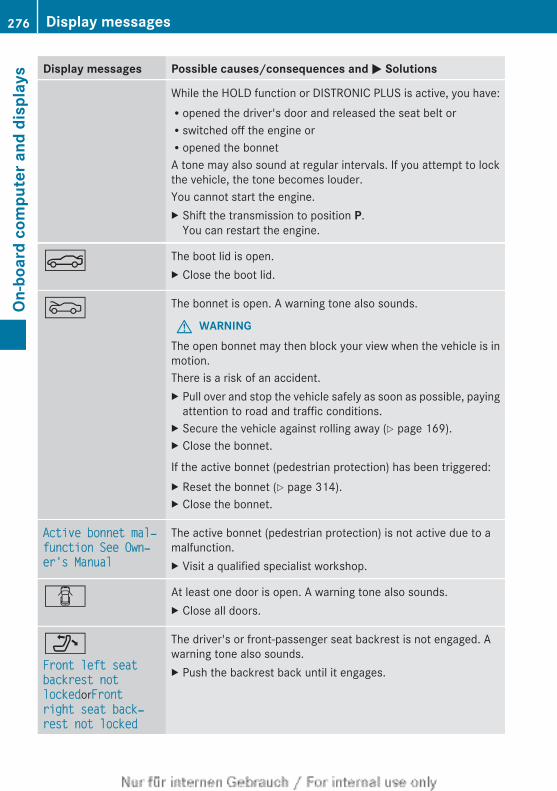
Display messages Possible causes/consequences and M Solutions
While the HOLD function or DISTRONIC PLUS is active, you have:Ropened the driver's door and released the seat belt orRswitched off the engine orRopened the bonnetA tone may also sound at regular intervals. If you attempt to lockthe vehicle, the tone becomes louder.You cannot start the engine.X Shift the transmission to position P.
You can restart the engine.
N The boot lid is open.X Close the boot lid.
M The bonnet is open. A warning tone also sounds.
G WARNINGThe open bonnet may then block your view when the vehicle is inmotion.There is a risk of an accident.X Pull over and stop the vehicle safely as soon as possible, paying
attention to road and traffic conditions.X Secure the vehicle against rolling away (Y page 169).X Close the bonnet.
If the active bonnet (pedestrian protection) has been triggered:X Reset the bonnet (Y page 314).X Close the bonnet.
Active bonnet mal‐function See Own‐er's Manual
The active bonnet (pedestrian protection) is not active due to amalfunction.X Visit a qualified specialist workshop.
C At least one door is open. A warning tone also sounds.X Close all doors.
_Front left seat backrest not lockedorFront right seat back‐rest not locked
The driver's or front-passenger seat backrest is not engaged. Awarning tone also sounds.X Push the backrest back until it engages.
276 Display messagesOn
-boa
rd c
ompu
ter a
nd d
ispl
ays
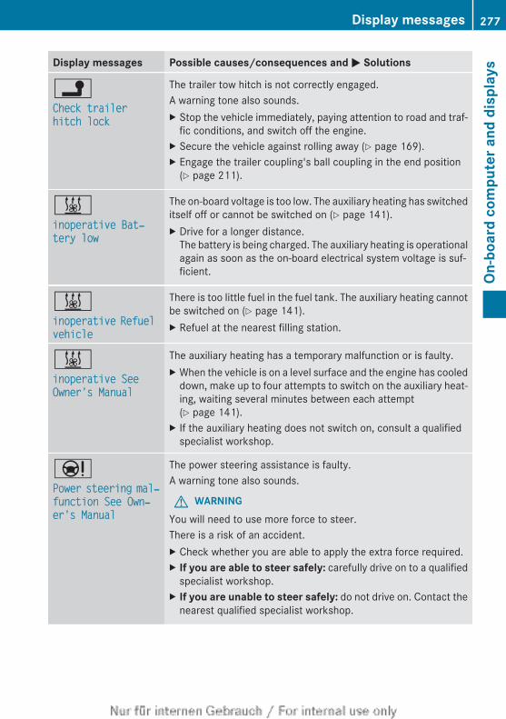
Display messages Possible causes/consequences and M Solutions
jCheck trailer hitch lock
The trailer tow hitch is not correctly engaged.A warning tone also sounds.X Stop the vehicle immediately, paying attention to road and traf-
fic conditions, and switch off the engine.X Secure the vehicle against rolling away (Y page 169).X Engage the trailer coupling's ball coupling in the end position
(Y page 211).
&inoperative Bat‐tery low
The on-board voltage is too low. The auxiliary heating has switcheditself off or cannot be switched on (Y page 141).X Drive for a longer distance.
The battery is being charged. The auxiliary heating is operationalagain as soon as the on-board electrical system voltage is suf-ficient.
&inoperative Refuel vehicle
There is too little fuel in the fuel tank. The auxiliary heating cannotbe switched on (Y page 141).X Refuel at the nearest filling station.
&inoperative See Owner's Manual
The auxiliary heating has a temporary malfunction or is faulty.X When the vehicle is on a level surface and the engine has cooled
down, make up to four attempts to switch on the auxiliary heat-ing, waiting several minutes between each attempt(Y page 141).
X If the auxiliary heating does not switch on, consult a qualifiedspecialist workshop.
ÐPower steering mal‐function See Own‐er's Manual
The power steering assistance is faulty.A warning tone also sounds.
G WARNINGYou will need to use more force to steer.There is a risk of an accident.X Check whether you are able to apply the extra force required.X If you are able to steer safely: carefully drive on to a qualified
specialist workshop.X If you are unable to steer safely: do not drive on. Contact the
nearest qualified specialist workshop.
Display messages 277
On-b
oard
com
pute
r and
dis
play
s
Z
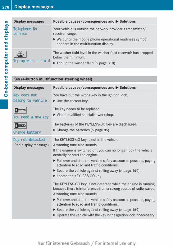
Display messages Possible causes/consequences and M Solutions
Telephone No service
Your vehicle is outside the network provider's transmitter/receiver range.X Wait until the mobile phone operational readiness symbol
appears in the multifunction display.
¥Top up washer fluid
The washer fluid level in the washer fluid reservoir has droppedbelow the minimum.X Top up the washer fluid (Y page 318).
Key (4-button multifunction steering wheel)
Display messages Possible causes/consequences and M Solutions
Key does not belong to vehicle
You have put the wrong key in the ignition lock.X Use the correct key.
+You need a new key
The key needs to be replaced.X Visit a qualified specialist workshop.
+Change battery
The batteries of the KEYLESS-GO key are discharged.X Change the batteries (Y page 85).
Key not detected(Red display message)
The KEYLESS-GO key is not in the vehicle.A warning tone also sounds.If the engine is switched off, you can no longer lock the vehiclecentrally or start the engine.X Pull over and stop the vehicle safely as soon as possible, paying
attention to road and traffic conditions.X Secure the vehicle against rolling away (Y page 169).X Locate the KEYLESS-GO key.
The KEYLESS-GO key is not detected while the engine is runningbecause there is interference from a strong source of radio waves.A warning tone also sounds.X Pull over and stop the vehicle safely as soon as possible, paying
attention to road and traffic conditions.X Secure the vehicle against rolling away (Y page 169).X Operate the vehicle with the key in the ignition lock if necessary.
278 Display messagesOn
-boa
rd c
ompu
ter a
nd d
ispl
ays
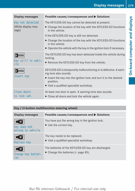
Display messages Possible causes/consequences and M Solutions
Key not detected(White display mes-sage)
The KEYLESS-GO key cannot be detected at present.X Change the location of the key with the KEYLESS-GO functions
in the vehicle.
If the KEYLESS-GO key is still not detected:X Change the location of the key with the KEYLESS-GO functions
in the vehicle.X Operate the vehicle with the key in the ignition lock if necessary.
+Key still in vehi‐cle
The KEYLESS-GO key has been detected inside the vehicle duringlocking.X Remove the KEYLESS-GO key from the vehicle.
+Insert key
KEYLESS-GO is temporarily malfunctioning or is defective. A warn-ing tone also sounds.X Insert the key into the ignition lock and turn it to the desired
position.X Visit a qualified specialist workshop.
Close doorsto lock veh.
At least one door is open. A warning tone also sounds.X Close all doors and lock the vehicle again.
Key (12-button multifunction steering wheel)
Display messages Possible causes/consequences and M Solutions
ÂKey does not belong to vehicle
You have put the wrong key in the ignition lock.X Use the correct key.
ÂReplace key
The key needs to be replaced.X Visit a qualified specialist workshop.
ÂChange key batter‐ies
The batteries of the KEYLESS-GO key are discharged.X Change the batteries (Y page 85).
Display messages 279
On-b
oard
com
pute
r and
dis
play
s
Z
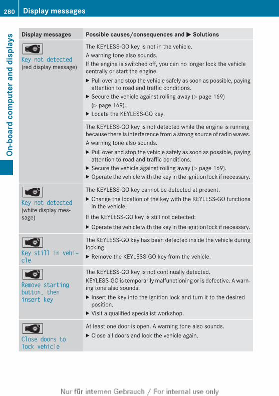
Display messages Possible causes/consequences and M Solutions
ÂKey not detected (red display message)
The KEYLESS-GO key is not in the vehicle.A warning tone also sounds.If the engine is switched off, you can no longer lock the vehiclecentrally or start the engine.X Pull over and stop the vehicle safely as soon as possible, paying
attention to road and traffic conditions.X Secure the vehicle against rolling away (Y page 169)
(Y page 169).X Locate the KEYLESS-GO key.
The KEYLESS-GO key is not detected while the engine is runningbecause there is interference from a strong source of radio waves.A warning tone also sounds.X Pull over and stop the vehicle safely as soon as possible, paying
attention to road and traffic conditions.X Secure the vehicle against rolling away (Y page 169).X Operate the vehicle with the key in the ignition lock if necessary.
ÂKey not detected (white display mes-sage)
The KEYLESS-GO key cannot be detected at present.X Change the location of the key with the KEYLESS-GO functions
in the vehicle.
If the KEYLESS-GO key is still not detected:X Operate the vehicle with the key in the ignition lock if necessary.
ÂKey still in vehi‐cle
The KEYLESS-GO key has been detected inside the vehicle duringlocking.X Remove the KEYLESS-GO key from the vehicle.
ÂRemove starting button, then insert key
The KEYLESS-GO key is not continually detected.KEYLESS-GO is temporarily malfunctioning or is defective. A warn-ing tone also sounds.X Insert the key into the ignition lock and turn it to the desired
position.X Visit a qualified specialist workshop.
ÂClose doors to lock vehicle
At least one door is open. A warning tone also sounds.X Close all doors and lock the vehicle again.
280 Display messagesOn
-boa
rd c
ompu
ter a
nd d
ispl
ays
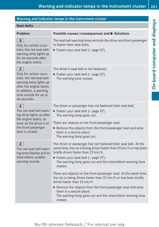
Warning and indicator lamps in the instrument cluster
Seat belts
Problem Possible causes/consequences and M Solutions
ü
Only for certain coun-tries: the red seat beltwarning lamp lights upfor six seconds afterthe engine starts.
The seat belt warning lamp reminds the driver and front passengerto fasten their seat belts.X Fasten your seat belt (Y page 57).
ü
Only for certain coun-tries: the red seat beltwarning lamp lights upafter the engine starts.In addition, a warningtone sounds for up tosix seconds.
The driver's seat belt is not fastened.X Fasten your seat belt (Y page 57).
The warning tone ceases.
ü
The red seat belt warn-ing lamp lights up afterthe engine starts, assoon as the driver's orthe front-passengerdoor is closed.
The driver or passenger has not fastened their seat belt.X Fasten your seat belt (Y page 57).
The warning lamp goes out.
There are objects on the front-passenger seat.X Remove the objects from the front-passenger seat and stow
them in a secure place.The warning lamp goes out.
ü
The red seat belt warn-ing lamp flashes and anintermittent audiblewarning sounds.
The driver or passenger has not fastened their seat belt. At thesame time, the car is being driven faster than 25 km/h or has beenbriefly driven faster than 25 km/h.X Fasten your seat belt (Y page 57).
The warning lamp goes out and the intermittent warning toneceases.
There are objects on the front-passenger seat. At the same time,the car is being driven faster than 25 km/h or has been brieflydriven faster than 25 km/h.X Remove the objects from the front-passenger seat and stow
them in a secure place.The warning lamp goes out and the intermittent warning toneceases.
Warning and indicator lamps in the instrument cluster 281
On-b
oard
com
pute
r and
dis
play
s
Z
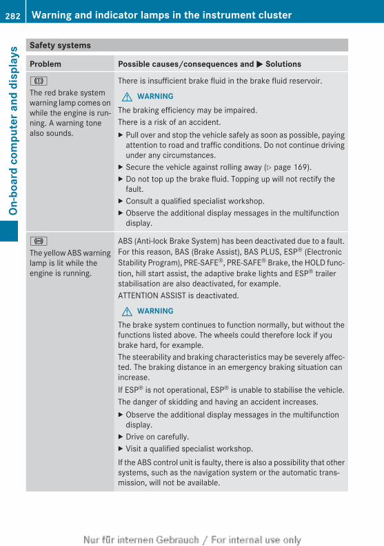
Safety systems
Problem Possible causes/consequences and M Solutions
J
The red brake systemwarning lamp comes onwhile the engine is run-ning. A warning tonealso sounds.
There is insufficient brake fluid in the brake fluid reservoir.
G WARNINGThe braking efficiency may be impaired.There is a risk of an accident.X Pull over and stop the vehicle safely as soon as possible, paying
attention to road and traffic conditions. Do not continue drivingunder any circumstances.
X Secure the vehicle against rolling away (Y page 169).X Do not top up the brake fluid. Topping up will not rectify the
fault.X Consult a qualified specialist workshop.X Observe the additional display messages in the multifunction
display.
!
The yellow ABS warninglamp is lit while theengine is running.
ABS (Anti-lock Brake System) has been deactivated due to a fault.For this reason, BAS (Brake Assist), BAS PLUS, ESP® (ElectronicStability Program), PRE-SAFE®, PRE-SAFE® Brake, the HOLD func-tion, hill start assist, the adaptive brake lights and ESP® trailerstabilisation are also deactivated, for example.ATTENTION ASSIST is deactivated.
G WARNINGThe brake system continues to function normally, but without thefunctions listed above. The wheels could therefore lock if youbrake hard, for example.The steerability and braking characteristics may be severely affec-ted. The braking distance in an emergency braking situation canincrease.If ESP® is not operational, ESP® is unable to stabilise the vehicle.The danger of skidding and having an accident increases.X Observe the additional display messages in the multifunction
display.X Drive on carefully.X Visit a qualified specialist workshop.If the ABS control unit is faulty, there is also a possibility that othersystems, such as the navigation system or the automatic trans-mission, will not be available.
282 Warning and indicator lamps in the instrument clusterOn
-boa
rd c
ompu
ter a
nd d
ispl
ays
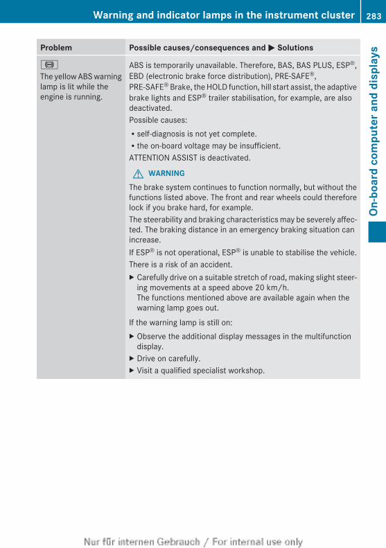
Problem Possible causes/consequences and M Solutions
!
The yellow ABS warninglamp is lit while theengine is running.
ABS is temporarily unavailable. Therefore, BAS, BAS PLUS, ESP®,EBD (electronic brake force distribution), PRE-SAFE®,PRE-SAFE® Brake, the HOLD function, hill start assist, the adaptivebrake lights and ESP® trailer stabilisation, for example, are alsodeactivated.Possible causes:Rself-diagnosis is not yet complete.Rthe on-board voltage may be insufficient.ATTENTION ASSIST is deactivated.
G WARNINGThe brake system continues to function normally, but without thefunctions listed above. The front and rear wheels could thereforelock if you brake hard, for example.The steerability and braking characteristics may be severely affec-ted. The braking distance in an emergency braking situation canincrease.If ESP® is not operational, ESP® is unable to stabilise the vehicle.There is a risk of an accident.X Carefully drive on a suitable stretch of road, making slight steer-
ing movements at a speed above 20 km/h.The functions mentioned above are available again when thewarning lamp goes out.
If the warning lamp is still on:X Observe the additional display messages in the multifunction
display.X Drive on carefully.X Visit a qualified specialist workshop.
Warning and indicator lamps in the instrument cluster 283
On-b
oard
com
pute
r and
dis
play
s
Z
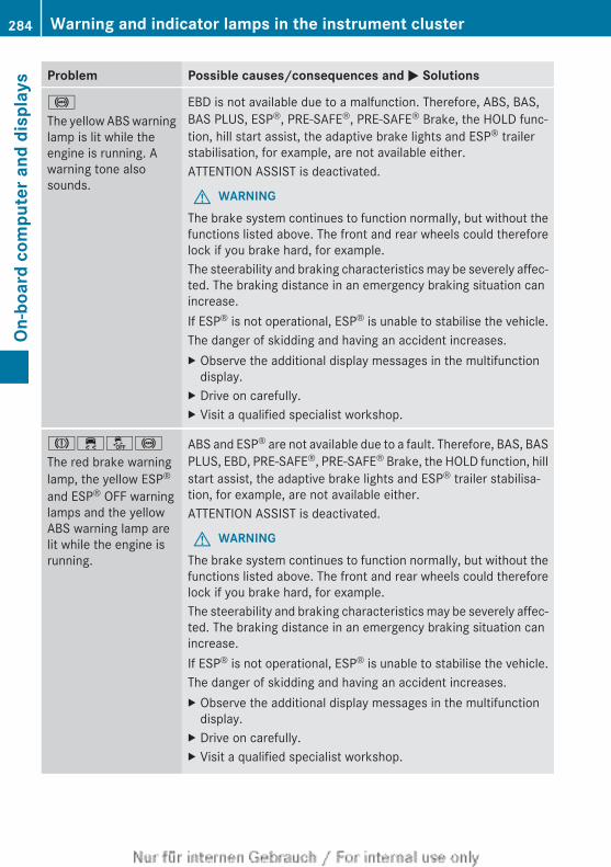
Problem Possible causes/consequences and M Solutions
!
The yellow ABS warninglamp is lit while theengine is running. Awarning tone alsosounds.
EBD is not available due to a malfunction. Therefore, ABS, BAS,BAS PLUS, ESP®, PRE-SAFE®, PRE-SAFE® Brake, the HOLD func-tion, hill start assist, the adaptive brake lights and ESP® trailerstabilisation, for example, are not available either.ATTENTION ASSIST is deactivated.
G WARNINGThe brake system continues to function normally, but without thefunctions listed above. The front and rear wheels could thereforelock if you brake hard, for example.The steerability and braking characteristics may be severely affec-ted. The braking distance in an emergency braking situation canincrease.If ESP® is not operational, ESP® is unable to stabilise the vehicle.The danger of skidding and having an accident increases.X Observe the additional display messages in the multifunction
display.X Drive on carefully.X Visit a qualified specialist workshop.
J֌!
The red brake warninglamp, the yellow ESP®
and ESP® OFF warninglamps and the yellowABS warning lamp arelit while the engine isrunning.
ABS and ESP® are not available due to a fault. Therefore, BAS, BASPLUS, EBD, PRE-SAFE®, PRE-SAFE® Brake, the HOLD function, hillstart assist, the adaptive brake lights and ESP® trailer stabilisa-tion, for example, are not available either.ATTENTION ASSIST is deactivated.
G WARNINGThe brake system continues to function normally, but without thefunctions listed above. The front and rear wheels could thereforelock if you brake hard, for example.The steerability and braking characteristics may be severely affec-ted. The braking distance in an emergency braking situation canincrease.If ESP® is not operational, ESP® is unable to stabilise the vehicle.The danger of skidding and having an accident increases.X Observe the additional display messages in the multifunction
display.X Drive on carefully.X Visit a qualified specialist workshop.
284 Warning and indicator lamps in the instrument clusterOn
-boa
rd c
ompu
ter a
nd d
ispl
ays
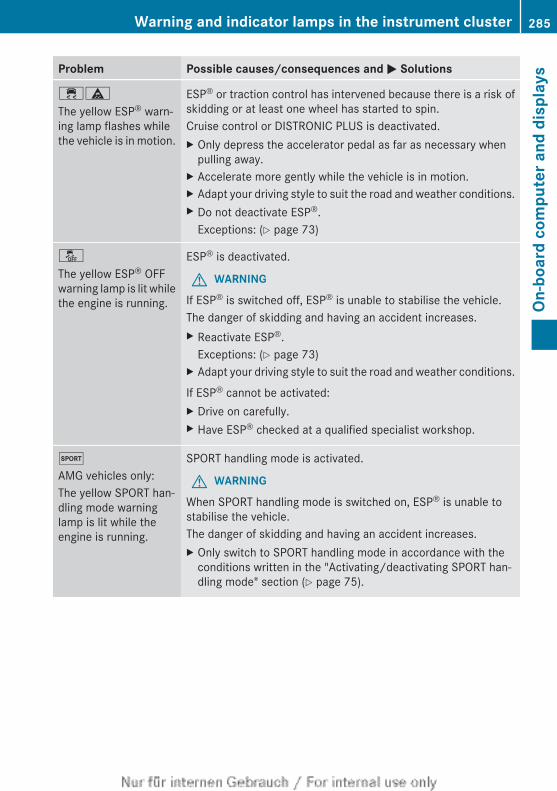
Problem Possible causes/consequences and M Solutions
֊
The yellow ESP® warn-ing lamp flashes whilethe vehicle is in motion.
ESP® or traction control has intervened because there is a risk ofskidding or at least one wheel has started to spin.Cruise control or DISTRONIC PLUS is deactivated.X Only depress the accelerator pedal as far as necessary when
pulling away.X Accelerate more gently while the vehicle is in motion.X Adapt your driving style to suit the road and weather conditions.X Do not deactivate ESP®.
Exceptions: (Y page 73)
å
The yellow ESP® OFFwarning lamp is lit whilethe engine is running.
ESP® is deactivated.
G WARNING
If ESP® is switched off, ESP® is unable to stabilise the vehicle.The danger of skidding and having an accident increases.X Reactivate ESP®.
Exceptions: (Y page 73)X Adapt your driving style to suit the road and weather conditions.
If ESP® cannot be activated:X Drive on carefully.X Have ESP® checked at a qualified specialist workshop.
M
AMG vehicles only:The yellow SPORT han-dling mode warninglamp is lit while theengine is running.
SPORT handling mode is activated.
G WARNING
When SPORT handling mode is switched on, ESP® is unable tostabilise the vehicle.The danger of skidding and having an accident increases.X Only switch to SPORT handling mode in accordance with the
conditions written in the "Activating/deactivating SPORT han-dling mode" section (Y page 75).
Warning and indicator lamps in the instrument cluster 285
On-b
oard
com
pute
r and
dis
play
s
Z
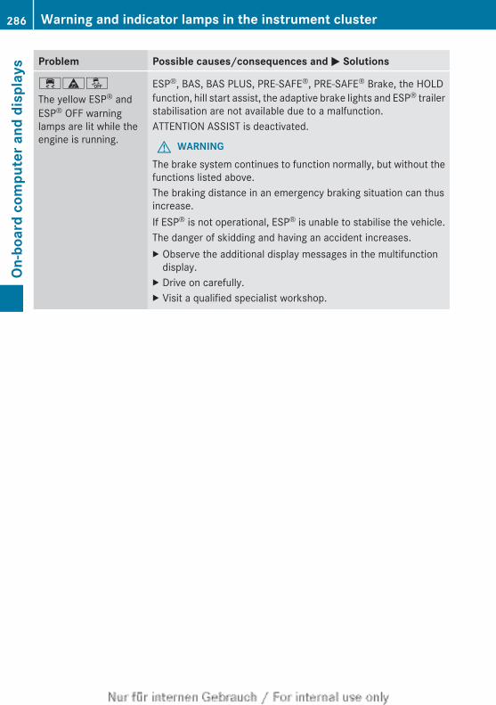
Problem Possible causes/consequences and M Solutions
÷äå
The yellow ESP® andESP® OFF warninglamps are lit while theengine is running.
ESP®, BAS, BAS PLUS, PRE-SAFE®, PRE-SAFE® Brake, the HOLDfunction, hill start assist, the adaptive brake lights and ESP® trailerstabilisation are not available due to a malfunction.ATTENTION ASSIST is deactivated.
G WARNINGThe brake system continues to function normally, but without thefunctions listed above.The braking distance in an emergency braking situation can thusincrease.If ESP® is not operational, ESP® is unable to stabilise the vehicle.The danger of skidding and having an accident increases.X Observe the additional display messages in the multifunction
display.X Drive on carefully.X Visit a qualified specialist workshop.
286 Warning and indicator lamps in the instrument clusterOn
-boa
rd c
ompu
ter a
nd d
ispl
ays
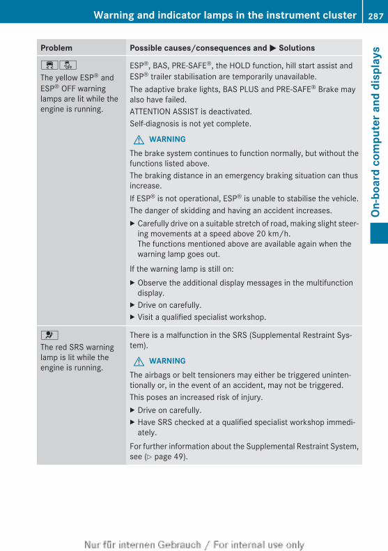
Problem Possible causes/consequences and M Solutions
֌
The yellow ESP® andESP® OFF warninglamps are lit while theengine is running.
ESP®, BAS, PRE-SAFE®, the HOLD function, hill start assist andESP® trailer stabilisation are temporarily unavailable.The adaptive brake lights, BAS PLUS and PRE-SAFE® Brake mayalso have failed.ATTENTION ASSIST is deactivated.Self-diagnosis is not yet complete.
G WARNINGThe brake system continues to function normally, but without thefunctions listed above.The braking distance in an emergency braking situation can thusincrease.If ESP® is not operational, ESP® is unable to stabilise the vehicle.The danger of skidding and having an accident increases.X Carefully drive on a suitable stretch of road, making slight steer-
ing movements at a speed above 20 km/h.The functions mentioned above are available again when thewarning lamp goes out.
If the warning lamp is still on:X Observe the additional display messages in the multifunction
display.X Drive on carefully.X Visit a qualified specialist workshop.
6
The red SRS warninglamp is lit while theengine is running.
There is a malfunction in the SRS (Supplemental Restraint Sys-tem).
G WARNINGThe airbags or belt tensioners may either be triggered uninten-tionally or, in the event of an accident, may not be triggered.This poses an increased risk of injury.X Drive on carefully.X Have SRS checked at a qualified specialist workshop immedi-
ately.For further information about the Supplemental Restraint System,see (Y page 49).
Warning and indicator lamps in the instrument cluster 287
On-b
oard
com
pute
r and
dis
play
s
Z
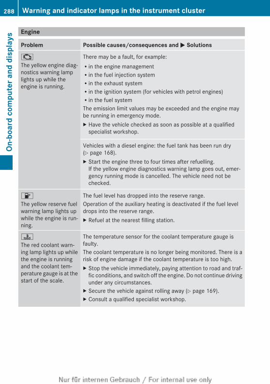
Engine
Problem Possible causes/consequences and M Solutions
;
The yellow engine diag-nostics warning lamplights up while theengine is running.
There may be a fault, for example:Rin the engine managementRin the fuel injection systemRin the exhaust systemRin the ignition system (for vehicles with petrol engines)Rin the fuel systemThe emission limit values may be exceeded and the engine maybe running in emergency mode.X Have the vehicle checked as soon as possible at a qualified
specialist workshop.
Vehicles with a diesel engine: the fuel tank has been run dry(Y page 168).X Start the engine three to four times after refuelling.
If the yellow engine diagnostics warning lamp goes out, emer-gency running mode is cancelled. The vehicle need not bechecked.
8
The yellow reserve fuelwarning lamp lights upwhile the engine is run-ning.
The fuel level has dropped into the reserve range.Operation of the auxiliary heating is deactivated if the fuel leveldrops into the reserve range.X Refuel at the nearest filling station.
?
The red coolant warn-ing lamp lights up whilethe engine is runningand the coolant tem-perature gauge is at thestart of the scale.
The temperature sensor for the coolant temperature gauge isfaulty.The coolant temperature is no longer being monitored. There is arisk of engine damage if the coolant temperature is too high.X Stop the vehicle immediately, paying attention to road and traf-
fic conditions, and switch off the engine. Do not continue drivingunder any circumstances.
X Secure the vehicle against rolling away (Y page 169).X Consult a qualified specialist workshop.
288 Warning and indicator lamps in the instrument clusterOn
-boa
rd c
ompu
ter a
nd d
ispl
ays
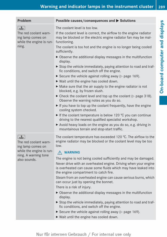
Problem Possible causes/consequences and M Solutions
?
The red coolant warn-ing lamp comes onwhile the engine is run-ning.
The coolant level is too low.If the coolant level is correct, the airflow to the engine radiatormay be blocked or the electric engine radiator fan may be mal-functioning.The coolant is too hot and the engine is no longer being cooledsufficiently.X Observe the additional display messages in the multifunction
display.X Stop the vehicle immediately, paying attention to road and traf-
fic conditions, and switch off the engine.X Secure the vehicle against rolling away (Y page 169).X Wait until the engine has cooled down.X Make sure that the air supply to the engine radiator is not
blocked, e.g. by frozen slush.X Check the coolant level and top up the coolant (Y page 318).
Observe the warning notes as you do so.X If you have to top up the coolant frequently, have the engine
cooling system checked.X If the coolant temperature is below 120 † you can continue
driving to the nearest qualified specialist workshop.X Avoid heavy loads on the engine as you do so, e.g. driving in
mountainous terrain and stop-start traffic.
?
The red coolant warn-ing lamp comes onwhile the engine is run-ning. A warning tonealso sounds.
The coolant temperature has exceeded 120 †. The airflow to theengine radiator may be blocked or the coolant level may be toolow.
G WARNINGThe engine is not being cooled sufficiently and may be damaged.Never drive with an overheated engine. Driving when your engineis overheated can cause some fluids which may have leaked intothe engine compartment to catch fire.Steam from an overheated engine can cause serious burns, whichcan occur just by opening the bonnet.There is a risk of injury.X Observe the additional display messages in the multifunction
display.X Stop the vehicle immediately, paying attention to road and traf-
fic conditions, and switch off the engine.X Secure the vehicle against rolling away (Y page 169).X Wait until the engine has cooled down.
Warning and indicator lamps in the instrument cluster 289
On-b
oard
com
pute
r and
dis
play
s
Z
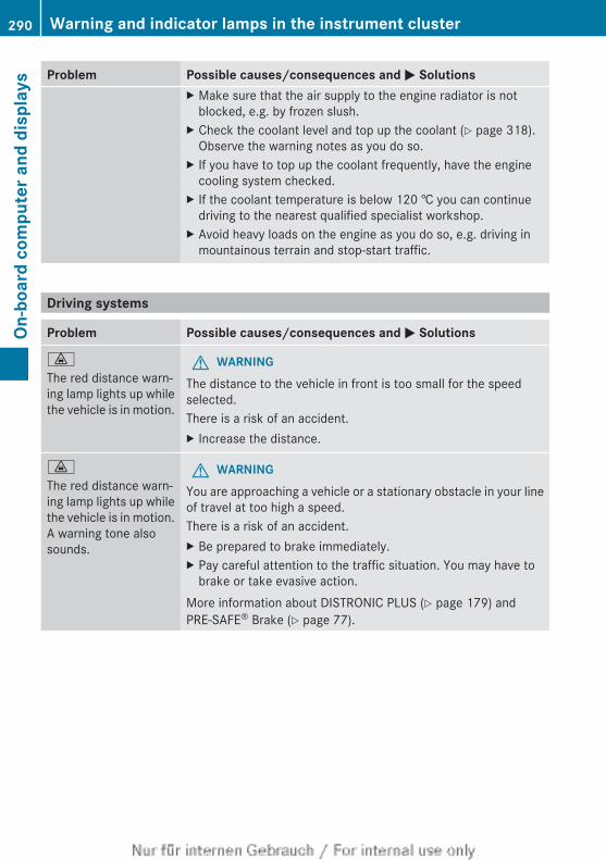
Problem Possible causes/consequences and M SolutionsX Make sure that the air supply to the engine radiator is not
blocked, e.g. by frozen slush.X Check the coolant level and top up the coolant (Y page 318).
Observe the warning notes as you do so.X If you have to top up the coolant frequently, have the engine
cooling system checked.X If the coolant temperature is below 120 † you can continue
driving to the nearest qualified specialist workshop.X Avoid heavy loads on the engine as you do so, e.g. driving in
mountainous terrain and stop-start traffic.
Driving systems
Problem Possible causes/consequences and M Solutions
·
The red distance warn-ing lamp lights up whilethe vehicle is in motion.
G WARNINGThe distance to the vehicle in front is too small for the speedselected.There is a risk of an accident.X Increase the distance.
·
The red distance warn-ing lamp lights up whilethe vehicle is in motion.A warning tone alsosounds.
G WARNINGYou are approaching a vehicle or a stationary obstacle in your lineof travel at too high a speed.There is a risk of an accident.X Be prepared to brake immediately.X Pay careful attention to the traffic situation. You may have to
brake or take evasive action.More information about DISTRONIC PLUS (Y page 179) andPRE-SAFE® Brake (Y page 77).
290 Warning and indicator lamps in the instrument clusterOn
-boa
rd c
ompu
ter a
nd d
ispl
ays
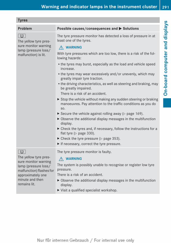
Tyres
Problem Possible causes/consequences and M Solutions
h
The yellow tyre pres-sure monitor warninglamp (pressure loss/malfunction) is lit.
The tyre pressure monitor has detected a loss of pressure in atleast one of the tyres.
G WARNINGWith tyre pressures which are too low, there is a risk of the fol-lowing hazards:Rthe tyres may burst, especially as the load and vehicle speed
increase.Rthe tyres may wear excessively and/or unevenly, which may
greatly impair tyre traction.Rthe driving characteristics, as well as steering and braking, may
be greatly impaired.There is a risk of an accident.
X Stop the vehicle without making any sudden steering or brakingmanoeuvres. Pay attention to the traffic conditions as you doso.
X Secure the vehicle against rolling away (Y page 169).X Observe the additional display messages in the multifunction
display.X Check the tyres and, if necessary, follow the instructions for a
flat tyre (Y page 330).X Check the tyre pressure (Y page 353).X If necessary, correct the tyre pressure.
h
The yellow tyre pres-sure monitor warninglamp (pressure loss/malfunction) flashes forapproximately oneminute and thenremains lit.
The tyre pressure monitor is faulty.
G WARNINGThe system is possibly unable to recognise or register low tyrepressure.There is a risk of an accident.X Observe the additional display messages in the multifunction
display.X Visit a qualified specialist workshop.
Warning and indicator lamps in the instrument cluster 291
On-b
oard
com
pute
r and
dis
play
s
Z

292
Useful information ............................ 294Loading guidelines ............................ 294Stowage areas .................................. 294Features ............................................. 299
293
Stow
ing
and
feat
ures
Useful information
i This Owner's Manual describes all mod-els, series and optional equipment for yourvehicle that were available at the time ofgoing to press. National variations are pos-sible. Note that your vehicle may not beequipped with all of the functions descri-bed. This is also the case for systems andfunctions relevant to safety.
i Read the information on qualified special-ist workshops: (Y page 28).
Loading guidelines
G WARNINGIf objects, luggage or loads are not secured ornot secured sufficiently, they could slip, tipover or be flung around and thereby hit vehicleoccupants. There is a risk of injury, especiallywhen braking or abruptly changing directions.Always store objects so that they cannot beflung around. Secure objects, luggage orloads against slipping or tipping before thejourney.
G WARNINGCombustion engines emit poisonous exhaustgases such as carbon monoxide. Exhaustgases can enter the vehicle interior if the bootlid is open when the engine is running, espe-cially if the vehicle is in motion. There is a riskof poisoning.Always switch off the engine before openingthe boot lid. Never drive with the boot lidopen.
The handling characteristics of a laden vehi-cle are dependent on the distribution of theload within the vehicle. For this reason, youshould observe the following notes whentransporting a load:Rwhen transporting a load, never exceed the
maximum permissible gross vehicle weight
or the permissible axle loads for the vehicle(including occupants).Rthe boot is the preferred place to carry
objects.Rposition heavy loads as far forwards as pos-
sible and as low down in the boot as pos-sible.Rthe load must not protrude above the upper
edge of the seat backrests.Ralways place the load against the rear or
front seat backrests. Make sure that theseat backrests are securely locked intoplace.Ralways place the load behind unoccupied
seats if possible.Ruse the lashing eyelets and the luggage
nets to transport loads and luggage.Ronly use lashing eyelets and fastening com-
ponents that are suitable for the weight andsize of the load.Rsecure the load with sufficiently strong and
wear-resistant lashing material. Pad sharpedges for protection.
i Load restraints are available at any quali-fied specialist workshop, e.g. a Mercedes-Benz Service Centre.
Stowage areas
Stowage spaces
Important safety notes
G WARNINGIf you do not correctly store objects in thevehicle interior, they can slip or be flungaround, thus striking vehicle occupants.There is a risk of injury, especially when brak-ing or abruptly changing directions.RAlways store objects so that they cannot be
flung around in these or in similar situa-tions.RAlways make sure that objects do not pro-
trude from stowage compartments, lug-gage nets or stowage nets.
294 Stowage areasSt
owin
g an
d fe
atur
es
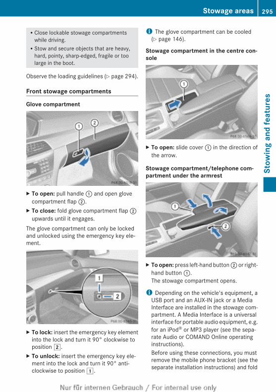
RClose lockable stowage compartmentswhile driving.RStow and secure objects that are heavy,
hard, pointy, sharp-edged, fragile or toolarge in the boot.
Observe the loading guidelines (Y page 294).
Front stowage compartments
Glove compartment
X To open: pull handle : and open glovecompartment flap ;.
X To close: fold glove compartment flap ;upwards until it engages.
The glove compartment can only be lockedand unlocked using the emergency key ele-ment.
X To lock: insert the emergency key elementinto the lock and turn it 90° clockwise toposition 2.
X To unlock: insert the emergency key ele-ment into the lock and turn it 90° anti-clockwise to position 1.
i The glove compartment can be cooled(Y page 146).
Stowage compartment in the centre con-sole
X To open: slide cover : in the direction ofthe arrow.
Stowage compartment/telephone com-partment under the armrest
X To open: press left-hand button ; or right-hand button :.The stowage compartment opens.
i Depending on the vehicle's equipment, aUSB port and an AUX-IN jack or a MediaInterface are installed in the stowage com-partment. A Media Interface is a universalinterface for portable audio equipment, e.g.for an iPod® or MP3 player (see the sepa-rate Audio or COMAND Online operatinginstructions).Before using these connections, you mustremove the mobile phone bracket (see theseparate installation instructions) and fold
Stowage areas 295
Stow
ing
and
feat
ures
Z
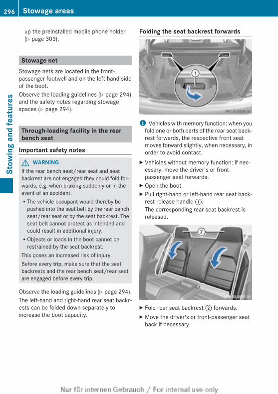
up the preinstalled mobile phone holder(Y page 303).
Stowage netStowage nets are located in the front-passenger footwell and on the left-hand sideof the boot.Observe the loading guidelines (Y page 294)and the safety notes regarding stowagespaces (Y page 294).
Through-loading facility in the rearbench seat
Important safety notes
G WARNINGIf the rear bench seat/rear seat and seatbackrest are not engaged they could fold for-wards, e.g. when braking suddenly or in theevent of an accident.RThe vehicle occupant would thereby be
pushed into the seat belt by the rear benchseat/rear seat or by the seat backrest. Theseat belt cannot protect as intended andcould result in additional injury.RObjects or loads in the boot cannot be
restrained by the seat backrest.This poses an increased risk of injury.Before every trip, make sure that the seatbackrests and the rear bench seat/rear seatare engaged before every trip.
Observe the loading guidelines (Y page 294).The left-hand and right-hand rear seat backr-ests can be folded down separately toincrease the boot capacity.
Folding the seat backrest forwards
i Vehicles with memory function: when youfold one or both parts of the rear seat back-rest forwards, the respective front seatmoves forward slightly, when necessary, inorder to avoid contact.
X Vehicles without memory function: if nec-essary, move the driver's or front-passenger seat forwards.
X Open the boot.X Pull right-hand or left-hand rear seat back-
rest release handle :.The corresponding rear seat backrest isreleased.
X Fold rear seat backrest ; forwards.X Move the driver's or front-passenger seat
back if necessary.
296 Stowage areasSt
owin
g an
d fe
atur
es
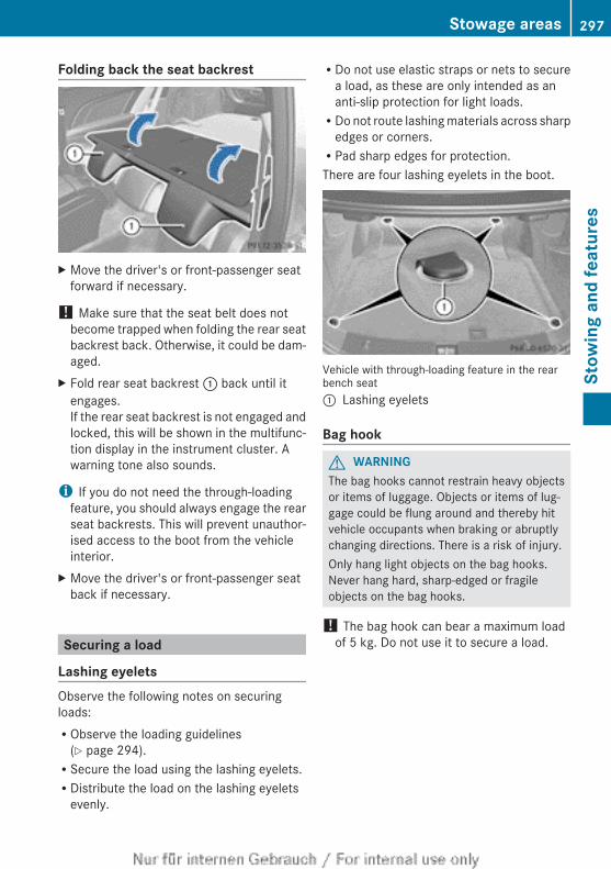
Folding back the seat backrest
X Move the driver's or front-passenger seatforward if necessary.
! Make sure that the seat belt does notbecome trapped when folding the rear seatbackrest back. Otherwise, it could be dam-aged.
X Fold rear seat backrest : back until itengages.If the rear seat backrest is not engaged andlocked, this will be shown in the multifunc-tion display in the instrument cluster. Awarning tone also sounds.
i If you do not need the through-loadingfeature, you should always engage the rearseat backrests. This will prevent unauthor-ised access to the boot from the vehicleinterior.
X Move the driver's or front-passenger seatback if necessary.
Securing a load
Lashing eyeletsObserve the following notes on securingloads:RObserve the loading guidelines
(Y page 294).RSecure the load using the lashing eyelets.RDistribute the load on the lashing eyelets
evenly.
RDo not use elastic straps or nets to securea load, as these are only intended as ananti-slip protection for light loads.RDo not route lashing materials across sharp
edges or corners.RPad sharp edges for protection.There are four lashing eyelets in the boot.
Vehicle with through-loading feature in the rearbench seat: Lashing eyelets
Bag hook
G WARNINGThe bag hooks cannot restrain heavy objectsor items of luggage. Objects or items of lug-gage could be flung around and thereby hitvehicle occupants when braking or abruptlychanging directions. There is a risk of injury.Only hang light objects on the bag hooks.Never hang hard, sharp-edged or fragileobjects on the bag hooks.
! The bag hook can bear a maximum loadof 5 kg. Do not use it to secure a load.
Stowage areas 297
Stow
ing
and
feat
ures
Z
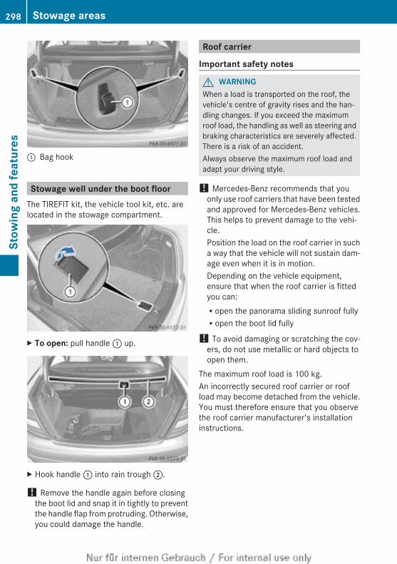
: Bag hook
Stowage well under the boot floorThe TIREFIT kit, the vehicle tool kit, etc. arelocated in the stowage compartment.
X To open: pull handle : up.
X Hook handle : into rain trough ;.
! Remove the handle again before closingthe boot lid and snap it in tightly to preventthe handle flap from protruding. Otherwise,you could damage the handle.
Roof carrier
Important safety notes
G WARNINGWhen a load is transported on the roof, thevehicle's centre of gravity rises and the han-dling changes. If you exceed the maximumroof load, the handling as well as steering andbraking characteristics are severely affected.There is a risk of an accident.Always observe the maximum roof load andadapt your driving style.
! Mercedes-Benz recommends that youonly use roof carriers that have been testedand approved for Mercedes-Benz vehicles.This helps to prevent damage to the vehi-cle.Position the load on the roof carrier in sucha way that the vehicle will not sustain dam-age even when it is in motion.Depending on the vehicle equipment,ensure that when the roof carrier is fittedyou can:Ropen the panorama sliding sunroof fullyRopen the boot lid fully
! To avoid damaging or scratching the cov-ers, do not use metallic or hard objects toopen them.
The maximum roof load is 100 kg.An incorrectly secured roof carrier or roofload may become detached from the vehicle.You must therefore ensure that you observethe roof carrier manufacturer's installationinstructions.
298 Stowage areasSt
owin
g an
d fe
atur
es
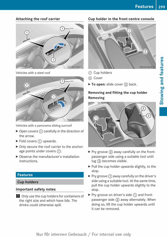
Attaching the roof carrier
Vehicles with a steel roof
Vehicles with a panorama sliding sunroofX Open covers : carefully in the direction of
the arrow.X Fold covers : upwards.X Only secure the roof carrier to the anchor-
age points under covers :.X Observe the manufacturer's installation
instructions.
Features
Cup holders
Important safety notes! Only use the cup holders for containers of
the right size and which have lids. Thedrinks could otherwise spill.
Cup holder in the front centre console
: Cup holders; CoverX To open: slide cover ; back.
Removing and fitting the cup holderRemoving
X Pry groove ; away carefully on the front-passenger side using a suitable tool untillug = becomes visible.
X Pull the cup holder upwards slightly, to thestop.
X Pry groove : away carefully on the driver'sside using a suitable tool. At the same time,pull the cup holder upwards slightly to thestop.
X Pry groove on driver's side : and front-passenger side ; away alternately. Whendoing so, lift the cup holder upwards untilit can be removed.
Features 299
Stow
ing
and
feat
ures
Z
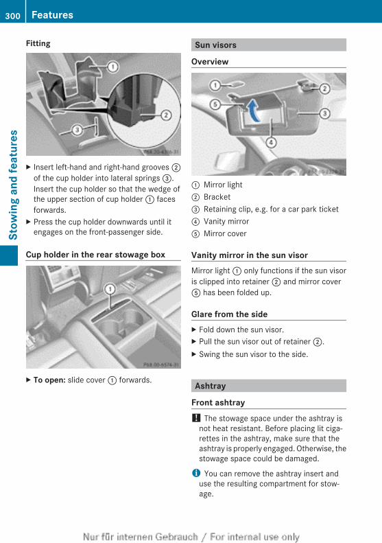
Fitting
X Insert left-hand and right-hand grooves ;of the cup holder into lateral springs =.Insert the cup holder so that the wedge ofthe upper section of cup holder : facesforwards.
X Press the cup holder downwards until itengages on the front-passenger side.
Cup holder in the rear stowage box
X To open: slide cover : forwards.
Sun visors
Overview
: Mirror light; Bracket= Retaining clip, e.g. for a car park ticket? Vanity mirrorA Mirror cover
Vanity mirror in the sun visorMirror light : only functions if the sun visoris clipped into retainer ; and mirror coverA has been folded up.
Glare from the sideX Fold down the sun visor.X Pull the sun visor out of retainer ;.X Swing the sun visor to the side.
Ashtray
Front ashtray! The stowage space under the ashtray is
not heat resistant. Before placing lit ciga-rettes in the ashtray, make sure that theashtray is properly engaged. Otherwise, thestowage space could be damaged.
i You can remove the ashtray insert anduse the resulting compartment for stow-age.
300 FeaturesSt
owin
g an
d fe
atur
es
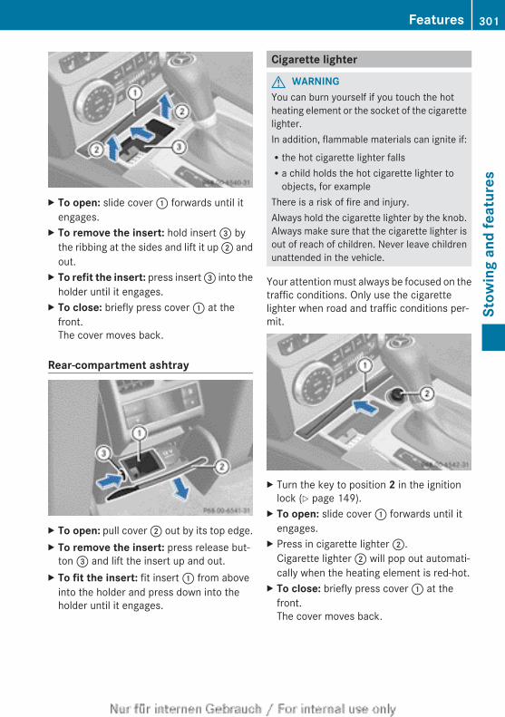
X To open: slide cover : forwards until itengages.
X To remove the insert: hold insert = bythe ribbing at the sides and lift it up ; andout.
X To refit the insert: press insert = into theholder until it engages.
X To close: briefly press cover : at thefront.The cover moves back.
Rear-compartment ashtray
X To open: pull cover ; out by its top edge.X To remove the insert: press release but-
ton = and lift the insert up and out.X To fit the insert: fit insert : from above
into the holder and press down into theholder until it engages.
Cigarette lighter
G WARNINGYou can burn yourself if you touch the hotheating element or the socket of the cigarettelighter.In addition, flammable materials can ignite if:Rthe hot cigarette lighter fallsRa child holds the hot cigarette lighter to
objects, for exampleThere is a risk of fire and injury.Always hold the cigarette lighter by the knob.Always make sure that the cigarette lighter isout of reach of children. Never leave childrenunattended in the vehicle.
Your attention must always be focused on thetraffic conditions. Only use the cigarettelighter when road and traffic conditions per-mit.
X Turn the key to position 2 in the ignitionlock (Y page 149).
X To open: slide cover : forwards until itengages.
X Press in cigarette lighter ;.Cigarette lighter ; will pop out automati-cally when the heating element is red-hot.
X To close: briefly press cover : at thefront.The cover moves back.
Features 301
Stow
ing
and
feat
ures
Z
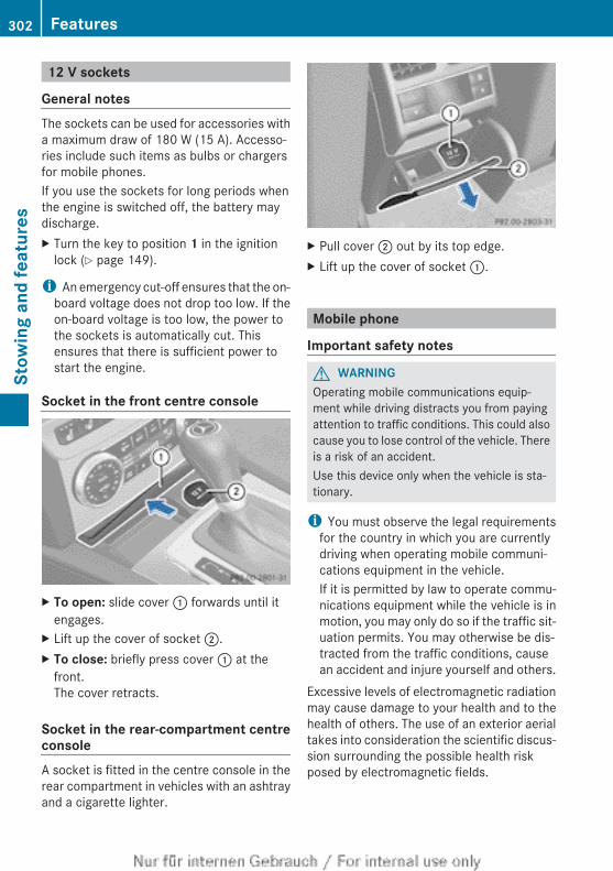
12 V sockets
General notesThe sockets can be used for accessories witha maximum draw of 180 W (15 A). Accesso-ries include such items as bulbs or chargersfor mobile phones.If you use the sockets for long periods whenthe engine is switched off, the battery maydischarge.X Turn the key to position 1 in the ignition
lock (Y page 149).
i An emergency cut-off ensures that the on-board voltage does not drop too low. If theon-board voltage is too low, the power tothe sockets is automatically cut. Thisensures that there is sufficient power tostart the engine.
Socket in the front centre console
X To open: slide cover : forwards until itengages.
X Lift up the cover of socket ;.X To close: briefly press cover : at the
front.The cover retracts.
Socket in the rear-compartment centreconsoleA socket is fitted in the centre console in therear compartment in vehicles with an ashtrayand a cigarette lighter.
X Pull cover ; out by its top edge.X Lift up the cover of socket :.
Mobile phone
Important safety notes
G WARNINGOperating mobile communications equip-ment while driving distracts you from payingattention to traffic conditions. This could alsocause you to lose control of the vehicle. Thereis a risk of an accident.Use this device only when the vehicle is sta-tionary.
i You must observe the legal requirementsfor the country in which you are currentlydriving when operating mobile communi-cations equipment in the vehicle.If it is permitted by law to operate commu-nications equipment while the vehicle is inmotion, you may only do so if the traffic sit-uation permits. You may otherwise be dis-tracted from the traffic conditions, causean accident and injure yourself and others.
Excessive levels of electromagnetic radiationmay cause damage to your health and to thehealth of others. The use of an exterior aerialtakes into consideration the scientific discus-sion surrounding the possible health riskposed by electromagnetic fields.
302 FeaturesSt
owin
g an
d fe
atur
es
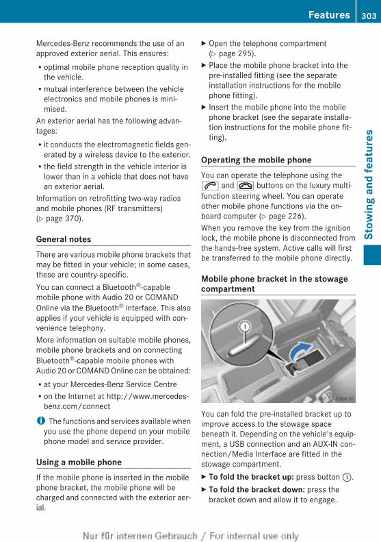
Mercedes-Benz recommends the use of anapproved exterior aerial. This ensures:Roptimal mobile phone reception quality in
the vehicle.Rmutual interference between the vehicle
electronics and mobile phones is mini-mised.
An exterior aerial has the following advan-tages:Rit conducts the electromagnetic fields gen-
erated by a wireless device to the exterior.Rthe field strength in the vehicle interior is
lower than in a vehicle that does not havean exterior aerial.
Information on retrofitting two-way radiosand mobile phones (RF transmitters)(Y page 370).
General notesThere are various mobile phone brackets thatmay be fitted in your vehicle; in some cases,these are country-specific.You can connect a Bluetooth®-capablemobile phone with Audio 20 or COMANDOnline via the Bluetooth® interface. This alsoapplies if your vehicle is equipped with con-venience telephony.More information on suitable mobile phones,mobile phone brackets and on connectingBluetooth®-capable mobile phones withAudio 20 or COMAND Online can be obtained:Rat your Mercedes-Benz Service CentreRon the Internet at http://www.mercedes-
benz.com/connect
i The functions and services available whenyou use the phone depend on your mobilephone model and service provider.
Using a mobile phoneIf the mobile phone is inserted in the mobilephone bracket, the mobile phone will becharged and connected with the exterior aer-ial.
X Open the telephone compartment(Y page 295).
X Place the mobile phone bracket into thepre-installed fitting (see the separateinstallation instructions for the mobilephone fitting).
X Insert the mobile phone into the mobilephone bracket (see the separate installa-tion instructions for the mobile phone fit-ting).
Operating the mobile phoneYou can operate the telephone using the6 and ~ buttons on the luxury multi-function steering wheel. You can operateother mobile phone functions via the on-board computer (Y page 226).When you remove the key from the ignitionlock, the mobile phone is disconnected fromthe hands-free system. Active calls will firstbe transferred to the mobile phone directly.
Mobile phone bracket in the stowagecompartment
You can fold the pre-installed bracket up toimprove access to the stowage spacebeneath it. Depending on the vehicle's equip-ment, a USB connection and an AUX-IN con-nection/Media Interface are fitted in thestowage compartment.X To fold the bracket up: press button :.X To fold the bracket down: press the
bracket down and allow it to engage.
Features 303
Stow
ing
and
feat
ures
Z
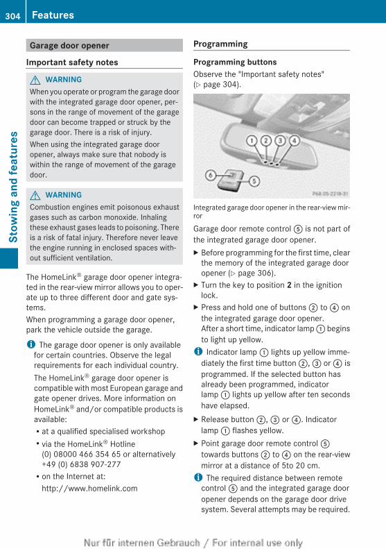
Garage door opener
Important safety notes
G WARNINGWhen you operate or program the garage doorwith the integrated garage door opener, per-sons in the range of movement of the garagedoor can become trapped or struck by thegarage door. There is a risk of injury.When using the integrated garage dooropener, always make sure that nobody iswithin the range of movement of the garagedoor.
G WARNINGCombustion engines emit poisonous exhaustgases such as carbon monoxide. Inhalingthese exhaust gases leads to poisoning. Thereis a risk of fatal injury. Therefore never leavethe engine running in enclosed spaces with-out sufficient ventilation.
The HomeLink® garage door opener integra-ted in the rear-view mirror allows you to oper-ate up to three different door and gate sys-tems.When programming a garage door opener,park the vehicle outside the garage.
i The garage door opener is only availablefor certain countries. Observe the legalrequirements for each individual country.The HomeLink® garage door opener iscompatible with most European garage andgate opener drives. More information onHomeLink® and/or compatible products isavailable:Rat a qualified specialised workshopRvia the HomeLink® Hotline
(0) 08000 466 354 65 or alternatively+49 (0) 6838 907-277Ron the Internet at:
http://www.homelink.com
Programming
Programming buttonsObserve the "Important safety notes"(Y page 304).
Integrated garage door opener in the rear-view mir-ror
Garage door remote control A is not part ofthe integrated garage door opener.X Before programming for the first time, clear
the memory of the integrated garage dooropener (Y page 306).
X Turn the key to position 2 in the ignitionlock.
X Press and hold one of buttons ; to ? onthe integrated garage door opener.After a short time, indicator lamp : beginsto light up yellow.
i Indicator lamp : lights up yellow imme-diately the first time button ;, = or ? isprogrammed. If the selected button hasalready been programmed, indicatorlamp : lights up yellow after ten secondshave elapsed.
X Release button ;, = or ?. Indicatorlamp : flashes yellow.
X Point garage door remote control Atowards buttons ; to ? on the rear-viewmirror at a distance of 5to 20 cm.
i The required distance between remotecontrol A and the integrated garage dooropener depends on the garage door drivesystem. Several attempts may be required.
304 FeaturesSt
owin
g an
d fe
atur
es
You should test every position for at least25 seconds before trying another position.
X Press and hold button B on remote controlA until indicator lamp : lights up green.If indicator lamp : lights up green orflashes, then programming has been suc-cessful.
X Release button B of remote control A ofthe garage door drive.
X If indicator lamp : blinks red: repeat theprogramming process for the correspond-ing button on the rear-view mirror. Whendoing so, vary the distance between remotecontrol A and the rear-view mirror.
i If the indicator lamp flashes green aftersuccessful programming, the garage doorsystem is using a rolling code. After pro-gramming, you must synchronise thegarage door opener integrated in the rear-view mirror with the receiver of the garagedoor system.
Synchronising the rolling codeObserve the "Important safety notes"(Y page 304).Your vehicle must be within range of thegarage door or exterior gate drive. Make surethat neither your vehicle nor any persons/objects are present within the sweep of thedoor or gate.X Turn the key to position 2 in the ignition
lock.X Press the programming button of the door
or gate drive (see the door or gate driveoperating instructions, e.g. under "Pro-gramming of additional remote controls").
i Usually, you now have 30seconds to ini-tiate the next step.
X Press previously programmed button ;,= or ? of the integrated garage dooropener until the door closes.The rolling code synchronisation is thencomplete.
Problems when programmingIf you have problems when programming theintegrated garage door opener, please notethe following:RCheck the transmitter frequency of garage
door drive remote control A. This can usu-ally be found on the back of the remotecontrol.RReplace the batteries in garage door
remote control A. This increases the like-lihood that garage door remote control Awill transmit a strong and precise signal tothe integrated garage door opener in therear-view mirror.RWhen programming, hold remote controlA at varying distances and angles from thebutton which you are programming. Try var-ious angles at a distance between 5and30 cm or at the same angle but at varyingdistances.RIf there is another remote control for the
same garage door drive, perform the pro-gramming steps again using this remotecontrol. Before performing these steps,make sure that new batteries have beenfitted in garage door drive remote controlA.RNote that some remote controls transmit
only for a limited period (the indicator lampon the remote control goes out). Press but-ton B on remote control A again beforetransmission ends.RAlign the aerial cable of the garage door
opener unit. This can improve signal recep-tion/transmission.
Opening or closing the garage doorOnce programmed, the integrated garagedoor opener will assume the function of thegarage door system's remote control. Pleasealso read the operating instructions for thegarage door system.
Features 305
Stow
ing
and
feat
ures
Z
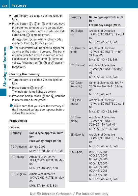
X Turn the key to position 2 in the ignitionlock.
X Press button ;, = or ? which you haveprogrammed to operate the garage door.Garage door system with a fixed code: indi-cator lamp : lights up green.Garage door system with a rolling code:indicator lamp : flashes green.
i The transmitter will transmit a signal foras long as the button is pressed. The trans-mission is halted after a maximum of tenseconds and indicator lamp : lights upyellow. Press button ;, = or ? again ifnecessary.
Clearing the memoryX Turn the key to position 2 in the ignition
lock.X Press buttons ; and ?.
The indicator lamp lights up yellow.X Press and hold buttons ; and ? until the
indicator lamp turns green.
i Make sure that you clear the memory ofthe integrated garage door opener beforeselling the vehicle.
Frequencies
Europe
Country Radio type approval num-berFrequency range (MHz)
AD (Andorra) 20 July 2005MHz: 27, 30, 40, 433, 868
AT (Austria) Article 6 of Directive1999/5/EC R&TTE 18 May05MHz: 27, 40, 433, 868
BE (Belgium) Article 6 of Directive1999/5/EC R&TTE 18 May05MHz: 27, 40, 433, 868
Country Radio type approval num-berFrequency range (MHz)
BG (Bulga-ria)
Article 6 of Directive1999/5/EC R&TTE 12 April07MHz: 27, 40, 433, 868
CH (Switzer-land)
Article 6 of Directive1999/5/EC R&TTE 1435727 May 05MHz: 27, 40, 433, 868
CY (Cyprus) Article 6 of Directive1999/5/EC R&TTE 5 May05MHz: 27, 40, 433, 868
CZ (CzechRepublic)
General Licence GL-30/R/2000 Reg No. 844 13 May05MHz: 27, 40, 433
DK (Den-mark)
Article 6 of Directive1999/5/EC R&TTE 20 April05MHz: 27, 40, 433, 868
DE (Ger-many)
Article 6 of Directive1999/5/EC R&TTE7519301 29 April 05MHz: 27, 40, 433, 868
EE (Estonia) Article 6 of Directive1999/5/EC R&TTE 11 May05MHz: 27, 40, 433, 868
ES (Spain) 000438/2005,000439/2005,000440/2005000441/2005,000445/2005,000446/2005000447/2005MHz: 27, 40, 433, 868
306 FeaturesSt
owin
g an
d fe
atur
es
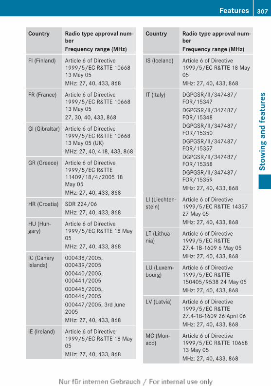
Country Radio type approval num-berFrequency range (MHz)
FI (Finland) Article 6 of Directive1999/5/EC R&TTE 1066813 May 05MHz: 27, 40, 433, 868
FR (France) Article 6 of Directive1999/5/EC R&TTE 1066813 May 0527, 30, 40, 433, 868
GI (Gibraltar) Article 6 of Directive1999/5/EC R&TTE 1066813 May 05 (UK)MHz: 27, 40, 418, 433, 868
GR (Greece) Article 6 of Directive1999/5/EC R&TTE11409/18/4/2005 18May 05MHz: 27, 40, 433, 868
HR (Croatia) SDR 224/06MHz: 27, 40, 433, 868
HU (Hun-gary)
Article 6 of Directive1999/5/EC R&TTE 18 May05MHz: 27, 40, 433, 868
IC (CanaryIslands)
000438/2005,000439/2005000440/2005,000441/2005000445/2005,000446/2005000447/2005, 3rd June2005MHz: 27, 40, 433, 868
IE (Ireland) Article 6 of Directive1999/5/EC R&TTE 18 May05MHz: 27, 40, 433, 868
Country Radio type approval num-berFrequency range (MHz)
IS (Iceland) Article 6 of Directive1999/5/EC R&TTE 18 May05MHz: 27, 40, 433, 868
IT (Italy) DGPGSR/II/347487/FOR/15347DGPGSR/II/347487/FOR/15348DGPGSR/II/347487/FOR/15350DGPGSR/II/347487/FOR/15357DGPGSR/II/347487/FOR/15358DGPGSR/II/347487/FOR/15359MHz: 27, 40, 433, 868
LI (Liechten-stein)
Article 6 of Directive1999/5/EC R&TTE 1435727 May 05MHz: 27, 40, 433, 868
LT (Lithua-nia)
Article 6 of Directive1999/5/EC R&TTE27.4-1B-1609 6 May 05MHz: 27, 40, 433, 868
LU (Luxem-bourg)
Article 6 of Directive1999/5/EC R&TTE150405/9538 24 May 05MHz: 27, 40, 433, 868
LV (Latvia) Article 6 of Directive1999/5/EC R&TTE27.4-1B-1609 26 April 06MHz: 27, 40, 433, 868
MC (Mon-aco)
Article 6 of Directive1999/5/EC R&TTE 1066813 May 05MHz: 27, 40, 433, 868
Features 307
Stow
ing
and
feat
ures
Z
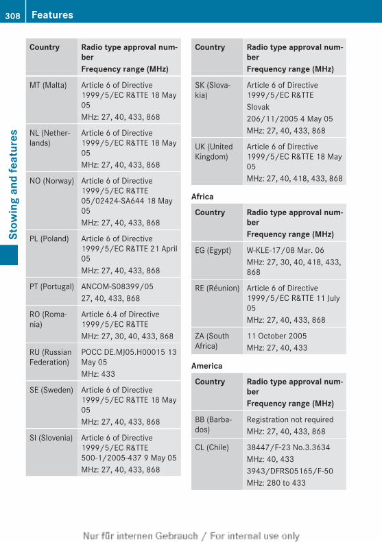
Country Radio type approval num-berFrequency range (MHz)
MT (Malta) Article 6 of Directive1999/5/EC R&TTE 18 May05MHz: 27, 40, 433, 868
NL (Nether-lands)
Article 6 of Directive1999/5/EC R&TTE 18 May05MHz: 27, 40, 433, 868
NO (Norway) Article 6 of Directive1999/5/EC R&TTE05/02424-SA644 18 May05MHz: 27, 40, 433, 868
PL (Poland) Article 6 of Directive1999/5/EC R&TTE 21 April05MHz: 27, 40, 433, 868
PT (Portugal) ANCOM-S08399/0527, 40, 433, 868
RO (Roma-nia)
Article 6.4 of Directive1999/5/EC R&TTEMHz: 27, 30, 40, 433, 868
RU (RussianFederation)
POCC DE.MJ05.H00015 13May 05MHz: 433
SE (Sweden) Article 6 of Directive1999/5/EC R&TTE 18 May05MHz: 27, 40, 433, 868
SI (Slovenia) Article 6 of Directive1999/5/EC R&TTE500-1/2005-437 9 May 05MHz: 27, 40, 433, 868
Country Radio type approval num-berFrequency range (MHz)
SK (Slova-kia)
Article 6 of Directive1999/5/EC R&TTESlovak206/11/2005 4 May 05MHz: 27, 40, 433, 868
UK (UnitedKingdom)
Article 6 of Directive1999/5/EC R&TTE 18 May05MHz: 27, 40, 418, 433, 868
Africa
Country Radio type approval num-berFrequency range (MHz)
EG (Egypt) W-KLE-17/08 Mar. 06MHz: 27, 30, 40, 418, 433,868
RE (Réunion) Article 6 of Directive1999/5/EC R&TTE 11 July05MHz: 27, 40, 433, 868
ZA (SouthAfrica)
11 October 2005MHz: 27, 40, 433
America
Country Radio type approval num-berFrequency range (MHz)
BB (Barba-dos)
Registration not requiredMHz: 27, 40, 433, 868
CL (Chile) 38447/F-23 No.3.3634MHz: 40, 4333943/DFRS05165/F-50MHz: 280 to 433
308 FeaturesSt
owin
g an
d fe
atur
es
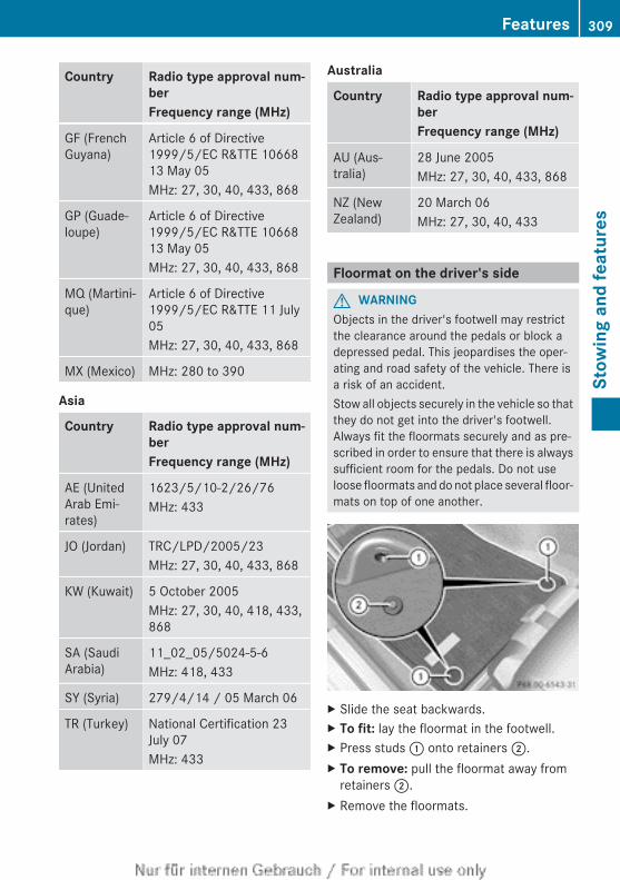
Country Radio type approval num-berFrequency range (MHz)
GF (FrenchGuyana)
Article 6 of Directive1999/5/EC R&TTE 1066813 May 05MHz: 27, 30, 40, 433, 868
GP (Guade-loupe)
Article 6 of Directive1999/5/EC R&TTE 1066813 May 05MHz: 27, 30, 40, 433, 868
MQ (Martini-que)
Article 6 of Directive1999/5/EC R&TTE 11 July05MHz: 27, 30, 40, 433, 868
MX (Mexico) MHz: 280 to 390
Asia
Country Radio type approval num-berFrequency range (MHz)
AE (UnitedArab Emi-rates)
1623/5/10-2/26/76MHz: 433
JO (Jordan) TRC/LPD/2005/23MHz: 27, 30, 40, 433, 868
KW (Kuwait) 5 October 2005MHz: 27, 30, 40, 418, 433,868
SA (SaudiArabia)
11_02_05/5024-5-6MHz: 418, 433
SY (Syria) 279/4/14 / 05 March 06
TR (Turkey) National Certification 23July 07MHz: 433
Australia
Country Radio type approval num-berFrequency range (MHz)
AU (Aus-tralia)
28 June 2005MHz: 27, 30, 40, 433, 868
NZ (NewZealand)
20 March 06MHz: 27, 30, 40, 433
Floormat on the driver's side
G WARNINGObjects in the driver's footwell may restrictthe clearance around the pedals or block adepressed pedal. This jeopardises the oper-ating and road safety of the vehicle. There isa risk of an accident.Stow all objects securely in the vehicle so thatthey do not get into the driver's footwell.Always fit the floormats securely and as pre-scribed in order to ensure that there is alwayssufficient room for the pedals. Do not useloose floormats and do not place several floor-mats on top of one another.
X Slide the seat backwards.X To fit: lay the floormat in the footwell.X Press studs : onto retainers ;.X To remove: pull the floormat away from
retainers ;.X Remove the floormats.
Features 309
Stow
ing
and
feat
ures
Z
Retrofitted anti-glare filmRetrofitted anti-glare film on the inside of thewindows can interfere with radio/mobiletelephone reception. This is particularly thecase for conductive or metallic-coated films.You can obtain information about anti-glarefilm from a qualified specialist workshop.
310 FeaturesSt
owin
g an
d fe
atur
es
Useful information ............................ 312ASSYST PLUS .................................... 312Engine compartment ........................ 313Care .................................................... 319
311
Mai
nten
ance
and
car
e
Useful information
i This Owner's Manual describes all mod-els, series and optional equipment for yourvehicle that were available at the time ofgoing to press. National variations are pos-sible. Note that your vehicle may not beequipped with all of the functions descri-bed. This is also the case for systems andfunctions relevant to safety.
i Read the information on qualified special-ist workshops: (Y page 28).
ASSYST PLUS
Service messagesThe ASSYST PLUS service interval displayinforms you of the next service due date.Information on the type of service and serviceintervals (see separate Service Booklet).You can obtain further information from aMercedes-Benz Service Centre.
i The ASSYST PLUS service interval displaydoes not show any information on theengine oil level. Observe the notes on theengine oil level (Y page 316).
The multifunction display shows a servicemessage for a few seconds, e.g.:RService A in .. daysRService A dueRService A overdue by ... daysDepending on the operating conditions of thevehicle, the remaining time or distance untilthe next service due date is displayed.The letter indicates which service is due. Astands for a minor service and B for a majorservice. A number or another letter may bedisplayed after the letter. This figure indicatesany necessary additional maintenance workto be performed.If you notify a qualified specialist workshop ofthis display, you will receive a statement onthe associated costs.
The ASSYST PLUS service interval displaydoes not take into account any periods oftime during which the battery is disconnec-ted.Maintaining the time-dependent serviceschedule:X Note down the service due date displayed
in the multifunction display before discon-necting the battery.
orX After reconnecting the battery, subtract
the battery disconnection periods from theservice date shown on the display.
Hiding a service messageX 4-button multifunction steering wheel:
press the C button.X 12-button multifunction steering
wheel: press the % or a button.
Displaying service messagesX Switch the ignition on.
4-button multifunction steering wheelX Use the V button to select the
Service menu.The service due date appears in the multi-function display.
12-button multifunction steering wheelX Press the = or ; button to select theService menu.
X Press the 9 or : button to select theASSYST PLUS submenu and confirm bypressing the a button.The service due date appears in the multi-function display.
312 ASSYST PLUSM
aint
enan
ce a
nd c
are
Information about Service
Resetting the ASSYST PLUS serviceinterval display! If the ASSYST PLUS service interval dis-
play has been inadvertently reset, this set-ting can be corrected at a qualified special-ist workshop.Have service work carried out as describedin the Service Booklet. This may otherwiselead to increased wear and damage to themajor assemblies or the vehicle.
A qualified specialist workshop, e.g. aMercedes-Benz Service Centre, will reset theASSYST PLUS service interval display afterthe service work has been carried out. Youcan also obtain further information on main-tenance work, for example.
Special service requirementsThe prescribed service interval is based onnormal operation of the vehicle. Service workwill need to be performed more often if thevehicle is operated under arduous conditionsor increased loads, for example:Rregular city driving with frequent intermedi-
ate stopsRif the vehicle is primarily used to travel
short distancesRfor frequent operation in mountainous ter-
rain or on poor road surfacesRif the engine is often left idling for long peri-
odsIn these or similar operating conditions, havethe air filter, engine oil and oil filter, for exam-ple, changed more frequently. The tyres mustbe checked more frequently if the vehicle isoperated under increased loads. Furtherinformation can be obtained at a qualifiedspecialist workshop, e.g. a Mercedes-BenzService Centre.
Driving abroadAn extensive Mercedes-Benz Service networkis also available in other countries. TheService Hotline's current telephone numbersfor use when you are abroad are to be foundin the "Mercedes-Benz Service24h" sectionof the Service Booklet.
Engine compartment
Bonnet
Important safety notes
G WARNINGAn unlocked bonnet may open while drivingand block your view. There is a risk of an acci-dent.Never unlock the bonnet while driving.
G WARNINGWhen being opened and closed, the bonnetmay suddenly fall into the closed position.There is a risk of injury to persons in the rangeof movement of the bonnet.Open and close the bonnet only when nobodyis in the range of movement.
G WARNINGIf you open the bonnet while the engine isoverheating or while there is a fire in theengine compartment, you could come intocontact with hot gases or other leakingservice products. There is a danger of injury.Allow an overheating engine to cool downbefore opening the bonnet. If there is a fire inthe engine compartment, leave the bonnetclosed and notify the fire brigade.
G WARNINGThere are parts in the engine compartmentthat move. Certain components may continueto run even if the ignition is switched off ormay suddenly start again, e.g. the radiatorfan. There is a danger of injury.
Engine compartment 313
Mai
nten
ance
and
car
e
Z
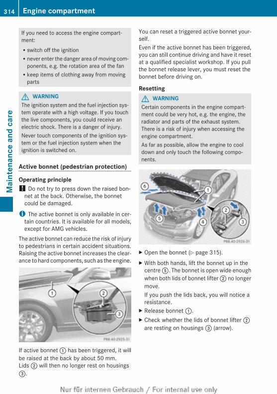
If you need to access the engine compart-ment:Rswitch off the ignitionRnever enter the danger area of moving com-
ponents, e.g. the rotation area of the fanRkeep items of clothing away from moving
parts
G WARNINGThe ignition system and the fuel injection sys-tem operate with a high voltage. If you touchthe live components, you could receive anelectric shock. There is a danger of injury.Never touch components of the ignition sys-tem or the fuel injection system when theignition is switched on.
Active bonnet (pedestrian protection)
Operating principle! Do not try to press down the raised bon-
net at the back. Otherwise, the bonnetcould be damaged.
i The active bonnet is only available in cer-tain countries. It is available for all models,except for AMG vehicles.
The active bonnet can reduce the risk of injuryto pedestrians in certain accident situations.Raising the active bonnet increases the clear-ance to hard components, such as the engine.
If active bonnet : has been triggered, it willbe raised at the back by about 50 mm.Lids ; will then no longer rest on housings=.
You can reset a triggered active bonnet your-self.Even if the active bonnet has been triggered,you can still continue driving and have it resetat a qualified specialist workshop. If you pullthe bonnet release lever, you must reset thebonnet before driving on.
ResettingG WARNINGCertain components in the engine compart-ment could be very hot, e.g. the engine, theradiator and parts of the exhaust system.There is a risk of injury when accessing theengine compartment.As far as possible, allow the engine to cooldown and only touch the following compo-nents.
X Open the bonnet (Y page 315).X With both hands, lift the bonnet up in the
centre A. The bonnet is open wide enoughwhen both lids of bonnet lifter ; no longermove.If you push the lids back, you will notice aresistance.
X Release bonnet :.X Check whether the lids of bonnet lifter ;
are resting on housings = (arrow).
314 Engine compartmentM
aint
enan
ce a
nd c
are
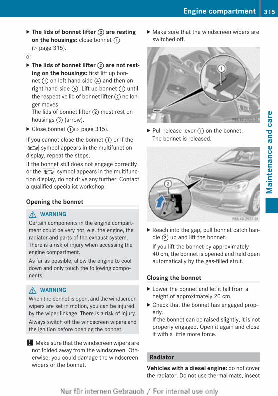
X The lids of bonnet lifter ; are resting on the housings: close bonnet :(Y page 315).
orX The lids of bonnet lifter ; are not rest-
ing on the housings: first lift up bon-net : on left-hand side ? and then onright-hand side B. Lift up bonnet : untilthe respective lid of bonnet lifter ; no lon-ger moves.The lids of bonnet lifter ; must rest onhousings = (arrow).
X Close bonnet :(Y page 315).
If you cannot close the bonnet : or if theL symbol appears in the multifunctiondisplay, repeat the steps.If the bonnet still does not engage correctlyor the L symbol appears in the multifunc-tion display, do not drive any further. Contacta qualified specialist workshop.
Opening the bonnet
G WARNINGCertain components in the engine compart-ment could be very hot, e.g. the engine, theradiator and parts of the exhaust system.There is a risk of injury when accessing theengine compartment.As far as possible, allow the engine to cooldown and only touch the following compo-nents.
G WARNINGWhen the bonnet is open, and the windscreenwipers are set in motion, you can be injuredby the wiper linkage. There is a risk of injury.Always switch off the windscreen wipers andthe ignition before opening the bonnet.
! Make sure that the windscreen wipers arenot folded away from the windscreen. Oth-erwise, you could damage the windscreenwipers or the bonnet.
X Make sure that the windscreen wipers areswitched off.
X Pull release lever : on the bonnet.The bonnet is released.
X Reach into the gap, pull bonnet catch han-dle ; up and lift the bonnet.If you lift the bonnet by approximately40 cm, the bonnet is opened and held openautomatically by the gas-filled strut.
Closing the bonnetX Lower the bonnet and let it fall from a
height of approximately 20 cm.X Check that the bonnet has engaged prop-
erly.If the bonnet can be raised slightly, it is notproperly engaged. Open it again and closeit with a little more force.
RadiatorVehicles with a diesel engine: do not coverthe radiator. Do not use thermal mats, insect
Engine compartment 315
Mai
nten
ance
and
car
e
Z
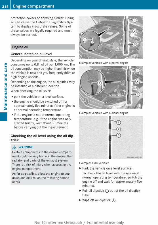
protection covers or anything similar. Doingso can cause the Onboard Diagnostics Sys-tem to display inaccurate values. Some ofthese values are legally required and mustalways be correct.
Engine oil
General notes on oil levelDepending on your driving style, the vehicleconsumes up to 0.8 l of oil per 1,000 km. Theoil consumption may be higher than this whenthe vehicle is new or if you frequently drive athigh engine speeds.Depending on the engine, the oil dipstick maybe installed at a different location.When checking the oil level:Rpark the vehicle on a level surface.Rthe engine should be switched off for
approximately five minutes if the engine isat normal operating temperature.Rif the engine is not at normal operating
temperature, e.g. if the engine was onlystarted briefly, wait about 30 minutesbefore carrying out the measurement.
Checking the oil level using the oil dip-stick
G WARNINGCertain components in the engine compart-ment could be very hot, e.g. the engine, theradiator and parts of the exhaust system.There is a risk of injury when accessing theengine compartment.As far as possible, allow the engine to cooldown and only touch the following compo-nents.
Example: vehicles with a petrol engine
Example: vehicles with a diesel engine
Example: AMG vehiclesX Park the vehicle on a level surface.
To check the oil level with the engine atnormal operating temperature, switch theengine off and wait for approximately fiveminutes.
X Pull oil dipstick : out of the oil dipsticktube.
X Wipe off oil dipstick :.
316 Engine compartmentM
aint
enan
ce a
nd c
are
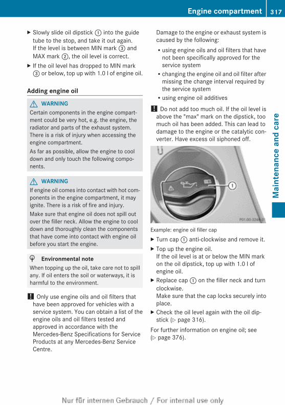
X Slowly slide oil dipstick : into the guidetube to the stop, and take it out again.If the level is between MIN mark = andMAX mark ;, the oil level is correct.
X If the oil level has dropped to MIN mark= or below, top up with 1.0 l of engine oil.
Adding engine oil
G WARNINGCertain components in the engine compart-ment could be very hot, e.g. the engine, theradiator and parts of the exhaust system.There is a risk of injury when accessing theengine compartment.As far as possible, allow the engine to cooldown and only touch the following compo-nents.
G WARNINGIf engine oil comes into contact with hot com-ponents in the engine compartment, it mayignite. There is a risk of fire and injury.Make sure that engine oil does not spill outover the filler neck. Allow the engine to cooldown and thoroughly clean the componentsthat have come into contact with engine oilbefore you start the engine.
H Environmental noteWhen topping up the oil, take care not to spillany. If oil enters the soil or waterways, it isharmful to the environment.
! Only use engine oils and oil filters thathave been approved for vehicles with aservice system. You can obtain a list of theengine oils and oil filters tested andapproved in accordance with theMercedes-Benz Specifications for ServiceProducts at any Mercedes-Benz ServiceCentre.
Damage to the engine or exhaust system iscaused by the following:Rusing engine oils and oil filters that have
not been specifically approved for theservice systemRchanging the engine oil and oil filter after
missing the change interval required bythe service systemRusing engine oil additives
! Do not add too much oil. If the oil level isabove the "max" mark on the dipstick, toomuch oil has been added. This can lead todamage to the engine or the catalytic con-verter. Have excess oil siphoned off.
Example: engine oil filler capX Turn cap : anti-clockwise and remove it.X Top up the engine oil.
If the oil level is at or below the MIN markon the oil dipstick, top up with 1.0 l ofengine oil.
X Replace cap : on the filler neck and turnclockwise.Make sure that the cap locks securely intoplace.
X Check the oil level again with the oil dip-stick (Y page 316).
For further information on engine oil; see(Y page 376).
Engine compartment 317
Mai
nten
ance
and
car
e
Z
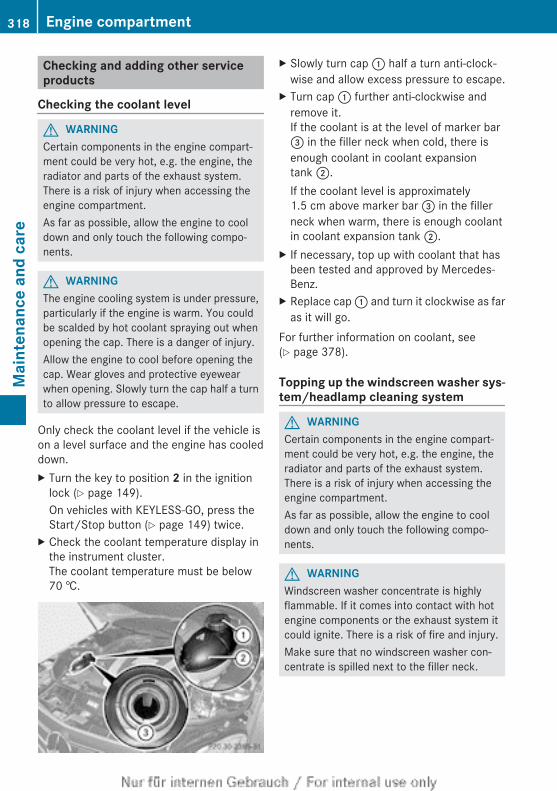
Checking and adding other serviceproducts
Checking the coolant level
G WARNINGCertain components in the engine compart-ment could be very hot, e.g. the engine, theradiator and parts of the exhaust system.There is a risk of injury when accessing theengine compartment.As far as possible, allow the engine to cooldown and only touch the following compo-nents.
G WARNINGThe engine cooling system is under pressure,particularly if the engine is warm. You couldbe scalded by hot coolant spraying out whenopening the cap. There is a danger of injury.Allow the engine to cool before opening thecap. Wear gloves and protective eyewearwhen opening. Slowly turn the cap half a turnto allow pressure to escape.
Only check the coolant level if the vehicle ison a level surface and the engine has cooleddown.X Turn the key to position 2 in the ignition
lock (Y page 149).On vehicles with KEYLESS-GO, press theStart/Stop button (Y page 149) twice.
X Check the coolant temperature display inthe instrument cluster.The coolant temperature must be below70 †.
X Slowly turn cap : half a turn anti-clock-wise and allow excess pressure to escape.
X Turn cap : further anti-clockwise andremove it.If the coolant is at the level of marker bar= in the filler neck when cold, there isenough coolant in coolant expansiontank ;.If the coolant level is approximately1.5 cm above marker bar = in the fillerneck when warm, there is enough coolantin coolant expansion tank ;.
X If necessary, top up with coolant that hasbeen tested and approved by Mercedes-Benz.
X Replace cap : and turn it clockwise as faras it will go.
For further information on coolant, see(Y page 378).
Topping up the windscreen washer sys-tem/headlamp cleaning system
G WARNINGCertain components in the engine compart-ment could be very hot, e.g. the engine, theradiator and parts of the exhaust system.There is a risk of injury when accessing theengine compartment.As far as possible, allow the engine to cooldown and only touch the following compo-nents.
G WARNINGWindscreen washer concentrate is highlyflammable. If it comes into contact with hotengine components or the exhaust system itcould ignite. There is a risk of fire and injury.Make sure that no windscreen washer con-centrate is spilled next to the filler neck.
318 Engine compartmentM
aint
enan
ce a
nd c
are
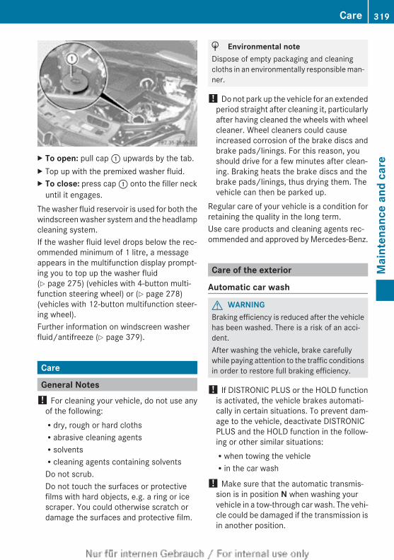
X To open: pull cap : upwards by the tab.X Top up with the premixed washer fluid.X To close: press cap : onto the filler neck
until it engages.The washer fluid reservoir is used for both thewindscreen washer system and the headlampcleaning system.If the washer fluid level drops below the rec-ommended minimum of 1 litre, a messageappears in the multifunction display prompt-ing you to top up the washer fluid(Y page 275) (vehicles with 4-button multi-function steering wheel) or (Y page 278)(vehicles with 12-button multifunction steer-ing wheel).Further information on windscreen washerfluid/antifreeze (Y page 379).
Care
General Notes! For cleaning your vehicle, do not use any
of the following:Rdry, rough or hard clothsRabrasive cleaning agentsRsolventsRcleaning agents containing solventsDo not scrub.Do not touch the surfaces or protectivefilms with hard objects, e.g. a ring or icescraper. You could otherwise scratch ordamage the surfaces and protective film.
H Environmental noteDispose of empty packaging and cleaningcloths in an environmentally responsible man-ner.
! Do not park up the vehicle for an extendedperiod straight after cleaning it, particularlyafter having cleaned the wheels with wheelcleaner. Wheel cleaners could causeincreased corrosion of the brake discs andbrake pads/linings. For this reason, youshould drive for a few minutes after clean-ing. Braking heats the brake discs and thebrake pads/linings, thus drying them. Thevehicle can then be parked up.
Regular care of your vehicle is a condition forretaining the quality in the long term.Use care products and cleaning agents rec-ommended and approved by Mercedes-Benz.
Care of the exterior
Automatic car wash
G WARNINGBraking efficiency is reduced after the vehiclehas been washed. There is a risk of an acci-dent.After washing the vehicle, brake carefullywhile paying attention to the traffic conditionsin order to restore full braking efficiency.
! If DISTRONIC PLUS or the HOLD functionis activated, the vehicle brakes automati-cally in certain situations. To prevent dam-age to the vehicle, deactivate DISTRONICPLUS and the HOLD function in the follow-ing or other similar situations:Rwhen towing the vehicleRin the car wash
! Make sure that the automatic transmis-sion is in position N when washing yourvehicle in a tow-through car wash. The vehi-cle could be damaged if the transmission isin another position.
Care 319
Mai
nten
ance
and
car
e
Z
! Make sure that:Rthe side windows and sliding sunroof are
closed completely.Rthe blower for the ventilation/heating is
switched off (OFF button is depressed).Rthe windscreen wiper switch is at posi-
tion 0.The vehicle could otherwise be damaged.
You can wash the vehicle in an automatic carwash from the very start.Wash off excess dirt before cleaning the vehi-cle in an automatic car wash.After using an automatic car wash, wipe offwax from the windscreen and the wiperblades. This will prevent smears and reducewiping noises caused by residue on the wind-screen.
Washing by handIn some countries, washing by hand is onlyallowed at specially equipped washing bays.Observe the legal requirements for each indi-vidual country.X Do not use hot water and do not wash the
vehicle in direct sunlight.X Use a soft sponge to clean.X Use a mild cleaning agent, such as a car
shampoo approved by Mercedes-Benz.X Thoroughly hose down the vehicle with a
gentle jet of water.X Do not point the water jet directly towards
the air inlet.X Use plenty of water and rinse out the
sponge frequently.X Rinse the vehicle with clean water and dry
thoroughly with a chamois.X Do not let the cleaning agent dry on the
paintwork.When using the vehicle in winter, remove alltraces of road salt deposits carefully and assoon as possible.
High-pressure cleaning equipment
G WARNINGThe water jet of circular-jet nozzles (dirt grind-ers) can cause damage not visible from theoutside to tyres or chassis components. Com-ponents damaged in this way can unexpect-edly fail. There is a risk of an accident.Do not use high-pressure cleaners with circu-lar-jet nozzles to clean the vehicle. Have dam-aged tyres or chassis components replacedimmediately.
! Always maintain a distance of at least30 cm between the vehicle and the high-pressure cleaner nozzle. Information aboutthe correct distance is available from theequipment manufacturer.Move the high-pressure cleaner nozzlearound when cleaning your vehicle.Do not aim directly at any of the following:RtyresRdoor gaps, roof gaps, joints etc.Relectrical componentsRbatteryRconnectorsRlightsRsealsRtrim elementsRventilation slotsDamaged seals or electrical componentscan lead to leaks or failures.
Cleaning the wheels! Do not use acidic wheel cleaning products
to remove brake dust. This could damagewheel bolts and brake components.
! Do not park up the vehicle for an extendedperiod straight after cleaning it, particularlyafter having cleaned the wheels with wheelcleaner. Wheel cleaners could causeincreased corrosion of the brake discs andbrake pads/linings. For this reason, youshould drive for a few minutes after clean-
320 CareM
aint
enan
ce a
nd c
are
ing. Braking heats the brake discs and thebrake pads/linings, thus drying them. Thevehicle can then be parked up.
Cleaning the paintworkScratches, corrosive deposits, areas affectedby corrosion and damage caused by inade-quate care cannot always be completelyrepaired. In such cases, visit a qualified spe-cialist workshop.X Remove impurities immediately, where
possible, whilst avoiding rubbing too hard.X Soak insect remains with insect remover
and rinse off the treated areas afterwards.X Soak bird droppings with water and rinse
off the treated areas afterwards.X Remove coolant, brake fluid, tree resin,
oils, fuels and greases by rubbing gentlywith a cloth soaked in petroleum ether orlighter fluid.
X Use tar remover to remove tar stains.X Use silicone remover to remove wax.
! Do not affix:RstickersRfilmsRmagnetic plates or similar itemsto painted surfaces. You could otherwisedamage the paintwork.
Care and treatment of matt paintworkIf your vehicle has a clear matt finish, observethe following instructions in order to avoiddamage to the paintwork due to incorrectcare.These notes also apply to light-alloy wheelswith a clear matt finish.
! Never polish the vehicle or the light alloywheels. Polishing makes the paintworkshiny.
! The following may cause the paint tobecome shiny and thus reduce the matteffect:RVigorous rubbing with unsuitable mate-
rials.RFrequent use of car washes.RWashing the vehicle in direct sunlight.
! Never use paint cleaner, buffing or pol-ishing products, or gloss preserver, e.g.wax. These products are only suitable forhigh-gloss surfaces. Their use on vehicleswith matt finish leads to considerable sur-face damage (shiny, spotted areas).Always have paintwork repairs carried outat a qualified specialist workshop.
! Do not use wash programs with a hot waxtreatment under any circumstances.
i The vehicle should preferably be washedby hand using a soft sponge, car shampooand plenty of water.
i Use only insect remover and car shampoofrom the range of recommended andapproved Mercedes-Benz care products.
Cleaning the windows
G WARNINGIf the windscreen wipers are set in motionwhen cleaning the windscreen or wiperblades, you could become trapped. There is adanger of injury.Always switch off the windscreen wipers andthe ignition before cleaning the windscreen orwiper blades.
! Only fold the windscreen wipers awayfrom the windscreen when vertical. Other-wise, you will damage the bonnet.
! Do not use dry cloths, abrasive products,solvents or cleaning agents containing sol-vents to clean the inside of the windows.Do not touch the insides of the windowswith hard objects, e.g. an ice scraper or
Care 321
Mai
nten
ance
and
car
e
Z
ring. There is otherwise a risk of damagingthe windows.
! Clean the water drainage channels of thewindscreen and the rear window at regularintervals. Deposits such as leaves, petalsand pollen may under certain circumstan-ces prevent water from draining away. Thiscan lead to corrosion damage and damageto electronic components.
X Clean the inside and outside of the win-dows with a damp cloth and a cleaningagent that is recommended and approvedby Mercedes-Benz.
Cleaning the wiper blades
G WARNINGIf the windscreen wipers are set in motionwhen cleaning the windscreen or wiperblades, you could become trapped. There is adanger of injury.Always switch off the windscreen wipers andthe ignition before cleaning the windscreen orwiper blades.
! Only fold the windscreen wipers awayfrom the windscreen when vertical. Other-wise, you will damage the bonnet.
! Do not pull on the wiper blade. Otherwise,the wiper blade could be damaged.
! Do not clean wiper blades too often anddo not rub them too hard. Otherwise, thegraphite coating could be damaged. Thiscould cause wiper noise.
! Hold the wiper arm securely when foldingback. The windscreen could be damaged ifthe wiper arm hits against it suddenly.
X Fold the wiper arms away from the wind-screen.
X Clean the wiper blades carefully using adamp cloth.
X Fold the windscreen wipers back againbefore switching on the ignition.
Cleaning the exterior lighting! Only use cleaning agents or cleaning
cloths that are suitable for plastic lenses.Unsuitable cleaning agents or cleaningcloths could scratch or damage the plasticlenses of the exterior lighting.
X Clean the plastic lenses of the exteriorlighting using a wet sponge and a mildcleaning agent, e.g. Mercedes-Benz carshampoo. Or clean the exterior lightingwith cleaning cloths.
Cleaning the mirror turn signal! Only use cleaning agents or cleaning
cloths that are suitable for plastic lenses.Unsuitable cleaning agents or cleaningcloths could scratch or damage the plasticlenses of the mirror turn signals.
X Clean the plastic lenses of the mirror turnsignals using a wet sponge and a mildcleaning agent, e.g. Mercedes-Benz carshampoo. Cleaning cloths may be used aswell.
Cleaning the sensors! If you clean the sensors with a high-pres-
sure cleaner, make sure that you keep adistance of at least 30 cm between thevehicle and the high-pressure cleaner noz-zle. Information about the correct distanceis available from the equipment manufac-turer.
322 CareM
aint
enan
ce a
nd c
are
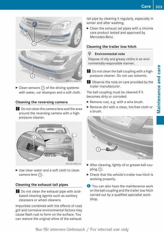
X Clean sensors : of the driving systemswith water, car shampoo and a soft cloth.
Cleaning the reversing camera! Do not clean the camera lens and the area
around the reversing camera with a high-pressure cleaner.
X Use clear water and a soft cloth to cleancamera lens :.
Cleaning the exhaust tail pipes! Do not clean the exhaust pipe with acid-
based cleaning agents such as sanitarycleansers or wheel cleaners.
Impurities combined with the effects of roadgrit and corrosive environmental factors maycause flash rust to form on the surface. Youcan restore the original shine of the exhaust
tail pipe by cleaning it regularly, especially inwinter and after washing.X Clean the exhaust tail pipes with a chrome
care product tested and approved byMercedes-Benz.
Cleaning the trailer tow hitch
H Environmental noteDispose of oily and greasy cloths in an envi-ronmentally-responsible manner.
! Do not clean the ball coupling with a high-pressure cleaner. Do not use solvents.
! Observe the note on care provided by thetrailer manufacturer.
The ball coupling must be cleaned if itbecomes dirty or corroded.X Remove rust, e.g. with a wire brush.X Remove dirt with a clean, lint-free cloth or
a brush.
X After cleaning, lightly oil or grease ball cou-pling :.
X Check that the vehicle's trailer tow hitch isworking properly.
i You can also have the maintenance workon the ball coupling and the trailer tow hitchcarried out by a qualified specialist work-shop.
Care 323
Mai
nten
ance
and
car
e
Z
Interior care
Cleaning the display! For cleaning, do not use any of the fol-
lowing:Ralcohol-based thinner or petrolRabrasive cleaning agentsRcommercially-available household clean-
ing agentsThese may damage the display surface. Donot put pressure on the display surfacewhen cleaning. This could lead to irrepara-ble damage to the display.
X Before cleaning the display, make sure thatit is switched off and has cooled down.
X Clean the display surface using a commer-cially available microfibre cloth and TFT/LCD display cleaner.
X Dry the display surface using a dry micro-fibre cloth.
Cleaning the plastic trim
G WARNINGCare products and cleaning agents containingsolvents can cause surfaces in the cockpit tobecome porous. This could result in plasticparts breaking away when the airbags aredeployed. There is a danger of injury.Do not use care products and cleaning agentscontaining solvents to clean the cockpit.
! Do not affix the following to plastic surfa-ces:RstickersRfilmsRscented oil bottles or similar itemsYou could otherwise damage the plastic.
! Do not allow cosmetics, insect repellentor sunscreen to come in contact with theplastic trim. This maintains the high-qualitylook of the surfaces.
X Wipe the plastic trim with a damp, lint-freecloth, e.g. a microfibre cloth.
X Heavy soiling: use car care and cleaningproducts recommended and approved byMercedes-Benz.The surface may change colour tempora-rily. Wait until the surface is dry again.
Cleaning the steering wheel and gear orselector leverX Thoroughly wipe with a damp cloth or use
leather care agents that have been recom-mended and approved by Mercedes-Benz.
Cleaning wooden trim and trim ele-ments! Do not use solvent-based cleaning agents
such as tar remover, wheel cleaners, pol-ishes or waxes. There is otherwise a risk ofdamaging the surface.
X Wipe the wooden trim and trim elementswith a damp, lint-free cloth, e.g. a microfi-bre cloth.
X Heavy soiling: use car care and cleaningproducts recommended and approved byMercedes-Benz.
Cleaning the seat covers
General notes! Do not use microfibre cloths to clean gen-
uine leather, artificial leather orAlcantara® covers. If used often, these candamage the cover.
i Note that regular care is essential tomake sure that the appearance and com-fort of the covers are retained over time.
Genuine leather seat coversLeather is a natural product.It has natural surface properties, e.g.:Runevenness in structureRmarks caused by growth and injuryRsubtle colour differences
324 CareM
aint
enan
ce a
nd c
are
These are characteristics of leather and notmaterial faults.
! To retain the natural appearance of theleather, observe the following cleaninginstructions:RClean genuine leather covers carefully
with a damp cloth and then wipe the cov-ers down with a dry cloth.RMake sure that the leather does not
become soaked. It may otherwisebecome rough and cracked.ROnly use leather care agents that have
been tested and approved by Mercedes-Benz. You can obtain these from a quali-fied specialist workshop.
Seat covers from other materials! Observe the following when cleaning:RClean artificial leather covers with a cloth
moistened with a solution containing1% detergent (e.g. washing-up liquid).RClean cloth covers with a microfibre
cloth moistened with a solution contain-ing 1% detergent (e.g. washing-up liquid).Rub carefully, and always wipe entireseat sections to avoid leaving visiblelines. Leave the seat to dry afterwards.Cleaning results depend on the type ofdirt and how long it has been there.RClean Alcantara® covers with a damp
cloth. Make sure that you wipe entireseat sections to avoid leaving visiblelines.
Cleaning the seat belts
G WARNINGSeat belts may be severely weakened ifbleached or coloured. This may lead to theseat belts, for example, tearing or failing in anaccident. There is an increased risk of injury,possibly even fatal.Never bleach or colour seat belts.
! Do not clean the seat belts using chemicalcleaning agents. Do not dry the seat belts
at temperatures above 80 † or in directsunlight.
X Use clean, lukewarm water and soap solu-tion.
Cleaning the roof lining and carpetsX Roof lining: if it is very dirty, use a soft
brush or a cleaning agent recommendedand approved by Mercedes-Benz.
X Carpets: use the carpet and textile clean-ing agents recommended and approved byMercedes-Benz.
Care 325
Mai
nten
ance
and
car
e
Z

326
Useful information ............................ 328Where will I find...? ........................... 328Flat tyre ............................................. 330Battery (vehicle) ................................ 334Jump-starting .................................... 338Towing and tow-starting .................. 340Electrical fuses ................................. 343
327
Brea
kdow
n as
sist
ance
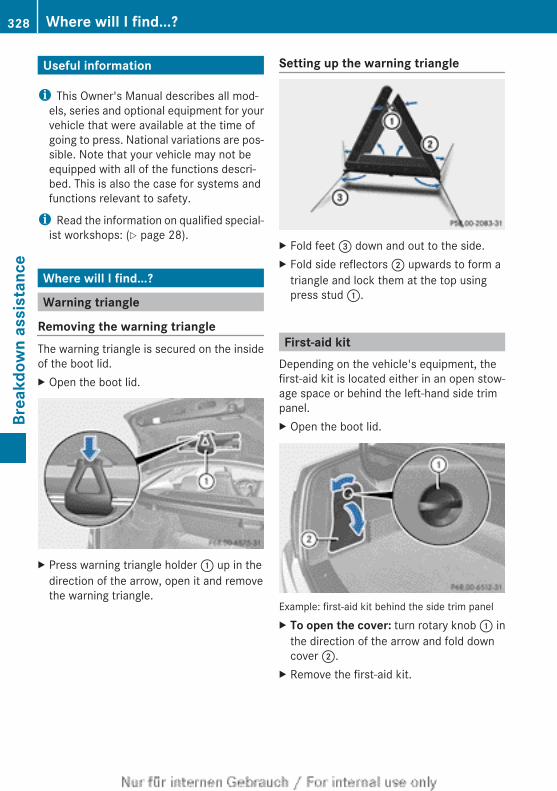
Useful information
i This Owner's Manual describes all mod-els, series and optional equipment for yourvehicle that were available at the time ofgoing to press. National variations are pos-sible. Note that your vehicle may not beequipped with all of the functions descri-bed. This is also the case for systems andfunctions relevant to safety.
i Read the information on qualified special-ist workshops: (Y page 28).
Where will I find...?
Warning triangle
Removing the warning triangleThe warning triangle is secured on the insideof the boot lid.X Open the boot lid.
X Press warning triangle holder : up in thedirection of the arrow, open it and removethe warning triangle.
Setting up the warning triangle
X Fold feet = down and out to the side.X Fold side reflectors ; upwards to form a
triangle and lock them at the top usingpress stud :.
First-aid kitDepending on the vehicle's equipment, thefirst-aid kit is located either in an open stow-age space or behind the left-hand side trimpanel.X Open the boot lid.
Example: first-aid kit behind the side trim panelX To open the cover: turn rotary knob : in
the direction of the arrow and fold downcover ;.
X Remove the first-aid kit.
328 Where will I find...?Br
eakd
own
assi
stan
ce
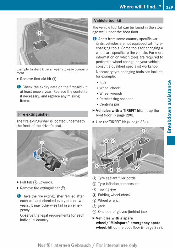
Example: first-aid kit in an open stowage compart-mentX Remove first-aid kit :.
i Check the expiry date on the first-aid kitat least once a year. Replace the contentsif necessary, and replace any missingitems.
Fire extinguisherThe fire extinguisher is located underneaththe front of the driver's seat.
X Pull tab : upwards.X Remove fire extinguisher ;.
i Have the fire extinguisher refilled aftereach use and checked every one or twoyears. It may otherwise fail in an emer-gency.Observe the legal requirements for eachindividual country.
Vehicle tool kitThe vehicle tool kit can be found in the stow-age well under the boot floor.
i Apart from some country-specific var-iants, vehicles are not equipped with tyre-changing tools. Some tools for changing awheel are specific to the vehicle. For moreinformation on which tools are required toperform a wheel change on your vehicle,consult a qualified specialist workshop.Necessary tyre-changing tools can include,for example:RJackRWheel chockRWheel wrenchRRatchet ring spannerRCentring pin
X Vehicles with a TIREFIT kit: lift up theboot floor (Y page 298).
X Use the TIREFIT kit (Y page 331).
: Tyre sealant filler bottle; Tyre inflation compressor= Towing eye? Folding wheel chockA Wheel wrenchB JackC One pair of gloves (behind jack)X Vehicles with a spare
wheel/"Minispare" emergency spare wheel: lift up the boot floor (Y page 298).
Where will I find...? 329
Brea
kdow
n as
sist
ance
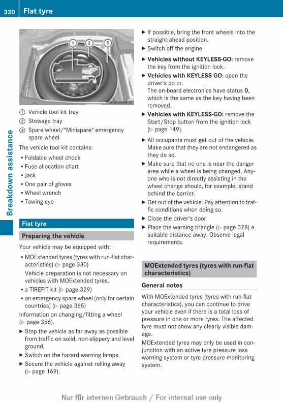
: Vehicle tool kit tray; Stowage tray= Spare wheel/"Minispare" emergency
spare wheelThe vehicle tool kit contains:RFoldable wheel chockRFuse allocation chartRJackROne pair of glovesRWheel wrenchRTowing eye
Flat tyre
Preparing the vehicleYour vehicle may be equipped with:RMOExtended tyres (tyres with run-flat char-
acteristics) (Y page 330)Vehicle preparation is not necessary onvehicles with MOExtended tyres.Ra TIREFIT kit (Y page 329)Ran emergency spare wheel (only for certain
countries) (Y page 365)Information on changing/fitting a wheel(Y page 356).X Stop the vehicle as far away as possible
from traffic on solid, non-slippery and levelground.
X Switch on the hazard warning lamps.X Secure the vehicle against rolling away
(Y page 169).
X If possible, bring the front wheels into thestraight-ahead position.
X Switch off the engine.X Vehicles without KEYLESS-GO: remove
the key from the ignition lock.X Vehicles with KEYLESS-GO: open the
driver's do or.The on-board electronics have status 0,which is the same as the key having beenremoved.
X Vehicles with KEYLESS-GO: remove theStart/Stop button from the ignition lock(Y page 149).
X All occupants must get out of the vehicle.Make sure that they are not endangered asthey do so.
X Make sure that no one is near the dangerarea while a wheel is being changed. Any-one who is not directly assisting in thewheel change should, for example, standbehind the barrier.
X Get out of the vehicle. Pay attention to traf-fic conditions when doing so.
X Close the driver's door.X Place the warning triangle (Y page 328) a
suitable distance away. Observe legalrequirements.
MOExtended tyres (tyres with run-flatcharacteristics)
General notesWith MOExtended tyres (tyres with run-flatcharacteristics), you can continue to driveyour vehicle even if there is a total loss ofpressure in one or more tyres. The affectedtyre must not show any clearly visible dam-age.MOExtended tyres may only be used in con-junction with an active tyre pressure losswarning system or tyre pressure monitoringsystem.
330 Flat tyreBr
eakd
own
assi
stan
ce
If the pressure loss warning message appears in the multifunction display:RVehicles with a 4-button multifunction
steering wheel:observe the instructions in the display mes-sages (Y page 270).RVehicles with a 12-button multifunc-
tion steering wheel:observe the instructions in the display mes-sages (Y page 271).Rcheck the tyre for damage.Rif driving on, observe the following notes.The maximum driving distance is approx-imately 80 km when the vehicle is partiallyladen and approximately 30 km when thevehicle is fully laden.In addition to the vehicle load, the driving dis-tance possible depends upon:RspeedRroad conditionRoutside temperatureThe driving distance possible in run-flat modemay be reduced by extreme driving condi-tions/manoeuvres, or it can be increasedthrough a moderate style of driving.The maximum permissible distance whichcan be driven in run-flat mode is counted fromthe moment the tyre pressure loss warningappears in the multifunction display.You must not exceed a maximum speed of80 km/h.
i When replacing one or all tyres, makesure that you use only:Rthe tyre size specified for the vehicle andRtyre(s) marked "MOExtended"If a tyre has gone flat and cannot bereplaced with an MOExtended tyre, astandard tyre may be used as a temporarymeasure. Make sure that you use theproper size and type (summer or wintertyre).
i Vehicles with MOExtended tyres are notequipped with a TIREFIT kit at the factory.
It is therefore recommended that you addi-tionally equip your vehicle with a TIREFIT kitif you fit tyres that do not feature run-flatcharacteristics, e.g. winter tyres. A TIREFITkit can be obtained from a qualified spe-cialist workshop.
Important safety notes
G WARNINGWhen driving in emergency mode, the drivingcharacteristics deteriorate, e.g. when corner-ing, accelerating quickly and when braking.There is a risk of accident.Do not exceed the stated maximum speed.Avoid abrupt steering and driving manoeu-vres, and driving over obstacles (kerbs, pot-holes, off-road). This applies in particular to aladen vehicle.Stop driving in emergency mode if:Ryou hear banging noises.Rthe vehicle starts to shake.Ryou see smoke and smell rubber.RESP® is intervening constantly.Rthere are tears in the sidewalls of the tyre.After driving in emergency mode, have thewheel rims checked at a qualified specialistworkshop with regard to their further use. Thefaulty tyre must be replaced.
TIREFIT kit
Important safety notesTIREFIT is a tyre sealant.You can use TIREFIT to seal punctures of upto 4 mm, particularly those in the tyre tread.You can use TIREFIT at outside temperaturesdown to Ò20 †.
Flat tyre 331
Brea
kdow
n as
sist
ance
Z
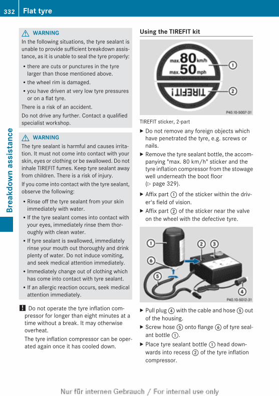
G WARNINGIn the following situations, the tyre sealant isunable to provide sufficient breakdown assis-tance, as it is unable to seal the tyre properly:Rthere are cuts or punctures in the tyre
larger than those mentioned above.Rthe wheel rim is damaged.Ryou have driven at very low tyre pressures
or on a flat tyre.There is a risk of an accident.Do not drive any further. Contact a qualifiedspecialist workshop.
G WARNINGThe tyre sealant is harmful and causes irrita-tion. It must not come into contact with yourskin, eyes or clothing or be swallowed. Do notinhale TIREFIT fumes. Keep tyre sealant awayfrom children. There is a risk of injury.If you come into contact with the tyre sealant,observe the following:RRinse off the tyre sealant from your skin
immediately with water.RIf the tyre sealant comes into contact with
your eyes, immediately rinse them thor-oughly with clean water.RIf tyre sealant is swallowed, immediately
rinse your mouth out thoroughly and drinkplenty of water. Do not induce vomiting,and seek medical attention immediately.RImmediately change out of clothing which
has come into contact with tyre sealant.RIf an allergic reaction occurs, seek medical
attention immediately.
! Do not operate the tyre inflation com-pressor for longer than eight minutes at atime without a break. It may otherwiseoverheat.The tyre inflation compressor can be oper-ated again once it has cooled down.
Using the TIREFIT kit
TIREFIT sticker, 2-partX Do not remove any foreign objects which
have penetrated the tyre, e.g. screws ornails.
X Remove the tyre sealant bottle, the accom-panying "max. 80 km/h" sticker and thetyre inflation compressor from the stowagewell underneath the boot floor(Y page 329).
X Affix part : of the sticker within the driv-er's field of vision.
X Affix part ; of the sticker near the valveon the wheel with the defective tyre.
X Pull plug ? with the cable and hose A outof the housing.
X Screw hose A onto flange B of tyre seal-ant bottle :.
X Place tyre sealant bottle : head down-wards into recess ; of the tyre inflationcompressor.
332 Flat tyreBr
eakd
own
assi
stan
ce
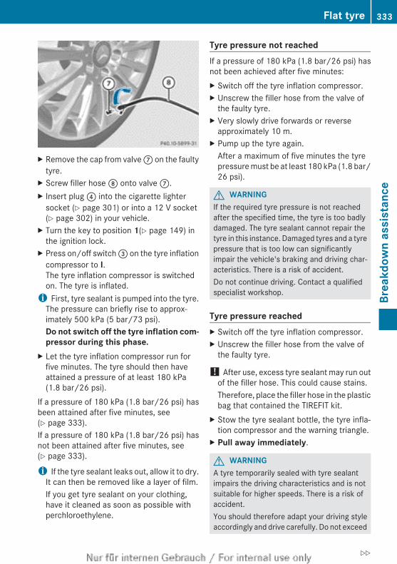
X Remove the cap from valve C on the faultytyre.
X Screw filler hose D onto valve C.X Insert plug ? into the cigarette lighter
socket (Y page 301) or into a 12 V socket(Y page 302) in your vehicle.
X Turn the key to position 1(Y page 149) inthe ignition lock.
X Press on/off switch = on the tyre inflationcompressor to I.The tyre inflation compressor is switchedon. The tyre is inflated.
i First, tyre sealant is pumped into the tyre.The pressure can briefly rise to approx-imately 500 kPa (5 bar/73 psi).Do not switch off the tyre inflation com-pressor during this phase.
X Let the tyre inflation compressor run forfive minutes. The tyre should then haveattained a pressure of at least 180 kPa(1.8 bar/26 psi).
If a pressure of 180 kPa (1.8 bar/26 psi) hasbeen attained after five minutes, see(Y page 333).If a pressure of 180 kPa (1.8 bar/26 psi) hasnot been attained after five minutes, see(Y page 333).
i If the tyre sealant leaks out, allow it to dry.It can then be removed like a layer of film.If you get tyre sealant on your clothing,have it cleaned as soon as possible withperchloroethylene.
Tyre pressure not reachedIf a pressure of 180 kPa (1.8 bar/26 psi) hasnot been achieved after five minutes:X Switch off the tyre inflation compressor.X Unscrew the filler hose from the valve of
the faulty tyre.X Very slowly drive forwards or reverse
approximately 10 m.X Pump up the tyre again.
After a maximum of five minutes the tyrepressure must be at least 180 kPa (1.8 bar/26 psi).
G WARNINGIf the required tyre pressure is not reachedafter the specified time, the tyre is too badlydamaged. The tyre sealant cannot repair thetyre in this instance. Damaged tyres and a tyrepressure that is too low can significantlyimpair the vehicle's braking and driving char-acteristics. There is a risk of accident.Do not continue driving. Contact a qualifiedspecialist workshop.
Tyre pressure reachedX Switch off the tyre inflation compressor.X Unscrew the filler hose from the valve of
the faulty tyre.
! After use, excess tyre sealant may run outof the filler hose. This could cause stains.Therefore, place the filler hose in the plasticbag that contained the TIREFIT kit.
X Stow the tyre sealant bottle, the tyre infla-tion compressor and the warning triangle.
X Pull away immediately.
G WARNINGA tyre temporarily sealed with tyre sealantimpairs the driving characteristics and is notsuitable for higher speeds. There is a risk ofaccident.You should therefore adapt your driving styleaccordingly and drive carefully. Do not exceed
Flat tyre 333
Brea
kdow
n as
sist
ance
Z
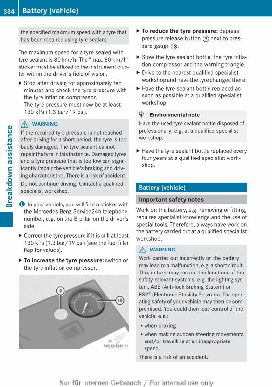
the specified maximum speed with a tyre thathas been repaired using tyre sealant.
The maximum speed for a tyre sealed withtyre sealant is 80 km/h. The "max. 80 km/h"sticker must be affixed to the instrument clus-ter within the driver's field of vision.X Stop after driving for approximately ten
minutes and check the tyre pressure withthe tyre inflation compressor.The tyre pressure must now be at least130 kPa (1.3 bar/19 psi).
G WARNINGIf the required tyre pressure is not reachedafter driving for a short period, the tyre is toobadly damaged. The tyre sealant cannotrepair the tyre in this instance. Damaged tyresand a tyre pressure that is too low can signif-icantly impair the vehicle's braking and driv-ing characteristics. There is a risk of accident.Do not continue driving. Contact a qualifiedspecialist workshop.
i In your vehicle, you will find a sticker withthe Mercedes-Benz Service24h telephonenumber, e.g. on the B-pillar on the driver'sside.
X Correct the tyre pressure if it is still at least130 kPa (1.3 bar/19 psi) (see the fuel fillerflap for values).
X To increase the tyre pressure: switch onthe tyre inflation compressor.
X To reduce the tyre pressure: depresspressure release button E next to pres-sure gauge F.
X Stow the tyre sealant bottle, the tyre infla-tion compressor and the warning triangle.
X Drive to the nearest qualified specialistworkshop and have the tyre changed there.
X Have the tyre sealant bottle replaced assoon as possible at a qualified specialistworkshop.
H Environmental noteHave the used tyre sealant bottle disposed ofprofessionally, e.g. at a qualified specialistworkshop.
X Have the tyre sealant bottle replaced everyfour years at a qualified specialist work-shop.
Battery (vehicle)
Important safety notesWork on the battery, e.g. removing or fitting,requires specialist knowledge and the use ofspecial tools. Therefore, always have work onthe battery carried out at a qualified specialistworkshop.
G WARNINGWork carried out incorrectly on the batterymay lead to a malfunction, e.g. a short circuit.This, in turn, may restrict the functions of thesafety-relevant systems, e.g. the lighting sys-tem, ABS (Anti-lock Braking System) orESP® (Electronic Stability Program). The oper-ating safety of your vehicle may then be com-promised. You could then lose control of thevehicle, e.g.:Rwhen brakingRwhen making sudden steering movements
and/or travelling at an inappropriatespeed.
There is a risk of an accident.
334 Battery (vehicle)Br
eakd
own
assi
stan
ce
In the event of a short circuit or similar situa-tion, inform a qualified specialist workshopimmediately. Do not drive any further. Youshould have all work involving the battery car-ried out at a qualified specialist workshop.
For further information about ABS(Y page 71) and ESP®(Y page 73).
G WARNINGElectrostatic build-up can lead to the creationof sparks, which could ignite the highly explo-sive gases of a battery. There is a risk of anexplosion.Before handling the battery, touch the vehiclebody to remove any existing electrostaticbuild-up.
The highly flammable gas mixture is createdwhile the battery is charging and when jump-starting.Always make sure that neither you nor thebattery is electrostatically charged. Electro-static charge is created, for example:Rby wearing synthetic fibre clothingRdue to friction between clothing and the
seatRwhen you pull or push the battery across
carpet or other synthetic materialsRwhen you rub the battery with a cloth
G WARNINGBattery acid is caustic. There is a risk of injury.Avoid contact with the skin, eyes or clothing.Do not inhale any battery gases. Do not leanover the battery. Keep children away frombatteries. Wash battery acid immediately withwater and seek medical attention.
G WARNINGDuring the charging process, a battery produ-ces hydrogen gas. If a short circuit occurs orsparks are created, the hydrogen gas canignite. There is a risk of an explosion.
RMake sure that the positive terminal of aconnected battery does not come into con-tact with vehicle parts.RNever place metal objects or tools on a bat-
tery.RIt is important that you observe the descri-
bed order of the battery terminals whenconnecting and disconnecting a battery.RWhen jump-starting, make sure that the
battery poles with identical polarity areconnected.RIt is particularly important to observe the
described order when connecting and dis-connecting the jump leads.RNever connect or disconnect the battery
terminals while the engine is running.
G WARNINGDuring charging and jump-starting, explosivegases can escape from the battery. There is arisk of an explosion.Particularly avoid fire, naked flames, creatingsparks and smoking. Ensure there is sufficientventilation while charging and jump-starting.Do not lean over a battery.
H Environmental noteBatteries contain pollutants.It is illegal to dispose of themwith the household rubbish.They must be collected sep-arately and disposed of in anenvironmentally responsiblerecycling system.Dispose of batteries in anenvironmentally responsiblemanner. Take dischargedbatteries to a qualified spe-cialist workshop or to a col-lection point for used batter-ies.
! Have the battery checked regularly at aqualified specialist workshop.
Battery (vehicle) 335
Brea
kdow
n as
sist
ance
Z
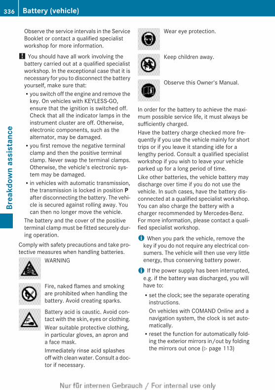
Observe the service intervals in the ServiceBooklet or contact a qualified specialistworkshop for more information.
! You should have all work involving thebattery carried out at a qualified specialistworkshop. In the exceptional case that it isnecessary for you to disconnect the batteryyourself, make sure that:Ryou switch off the engine and remove the
key. On vehicles with KEYLESS-GO,ensure that the ignition is switched off.Check that all the indicator lamps in theinstrument cluster are off. Otherwise,electronic components, such as thealternator, may be damaged.Ryou first remove the negative terminal
clamp and then the positive terminalclamp. Never swap the terminal clamps.Otherwise, the vehicle's electronic sys-tem may be damaged.Rin vehicles with automatic transmission,
the transmission is locked in position Pafter disconnecting the battery. The vehi-cle is secured against rolling away. Youcan then no longer move the vehicle.
The battery and the cover of the positiveterminal clamp must be fitted securely dur-ing operation.
Comply with safety precautions and take pro-tective measures when handling batteries.
WARNING
Fire, naked flames and smokingare prohibited when handling thebattery. Avoid creating sparks.
Battery acid is caustic. Avoid con-tact with the skin, eyes or clothing.Wear suitable protective clothing,in particular gloves, an apron anda face mask.Immediately rinse acid splashesoff with clean water. Consult a doc-tor if necessary.
Wear eye protection.
Keep children away.
Observe this Owner's Manual.
In order for the battery to achieve the maxi-mum possible service life, it must always besufficiently charged.Have the battery charge checked more fre-quently if you use the vehicle mainly for shorttrips or if you leave it standing idle for alengthy period. Consult a qualified specialistworkshop if you wish to leave your vehicleparked up for a long period of time.Like other batteries, the vehicle battery maydischarge over time if you do not use thevehicle. In such cases, have the battery dis-connected at a qualified specialist workshop.You can also charge the battery with acharger recommended by Mercedes-Benz.For more information, please contact a quali-fied specialist workshop.
i When you park the vehicle, remove thekey if you do not require any electrical con-sumers. The vehicle will then use very littleenergy, thus conserving battery power.
i If the power supply has been interrupted,e.g. if the battery was discharged, you willhave to:Rset the clock; see the separate operating
instructions.On vehicles with COMAND Online and anavigation system, the clock is set auto-matically.Rreset the function for automatically fold-
ing the exterior mirrors in/out by foldingthe mirrors out once (Y page 113)
336 Battery (vehicle)Br
eakd
own
assi
stan
ce
Charging the battery
G WARNINGDuring charging and jump-starting, explosivegases can escape from the battery. There is arisk of an explosion.Particularly avoid fire, naked flames, creatingsparks and smoking. Ensure there is sufficientventilation while charging and jump-starting.Do not lean over a battery.
G WARNINGBattery acid is caustic. There is a risk of injury.Avoid contact with the skin, eyes or clothing.Do not inhale any battery gases. Do not leanover the battery. Keep children away frombatteries. Wash battery acid immediately withwater and seek medical attention.
G WARNINGA discharged battery can freeze at tempera-tures below freezing point. When jump-start-ing the vehicle or charging the battery, gasescan escape from the battery. There is a risk ofan explosion.Allow the frozen battery to thaw out beforecharging it or jump-starting.
! Only charge the installed battery with abattery charger which has been tested andapproved by Mercedes-Benz. These batterychargers allow the battery to be chargedwhile still installed in the vehicle.
! Only use battery chargers with a maxi-mum charging voltage of 14.8 V.
! Only charge the battery using the jump-start connection point.
The jump-starting connection point is in theengine compartment (Y page 338).X Open the bonnet.X Connect the battery charger to the positive
terminal and earth point in the same orderas when connecting the donor battery inthe jump-starting procedure(Y page 338).
X Read the battery charger's operatinginstructions before charging the battery.
Battery (vehicle) 337
Brea
kdow
n as
sist
ance
Z
Jump-starting
For the jump-starting procedure, use only the jump-starting connection point, consisting of apositive terminal and an earth point, in the engine compartment.
G WARNINGBattery acid is caustic. There is a risk of injury.Avoid contact with the skin, eyes or clothing. Do not inhale any battery gases. Do not lean overthe battery. Keep children away from batteries. Wash battery acid immediately with water andseek medical attention.
G WARNINGDuring charging and jump-starting, explosive gases can escape from the battery. There is a riskof an explosion.Particularly avoid fire, naked flames, creating sparks and smoking. Ensure there is sufficientventilation while charging and jump-starting. Do not lean over a battery.
G WARNINGDuring the charging process, a battery produces hydrogen gas. If a short circuit occurs or sparksare created, the hydrogen gas can ignite. There is a risk of an explosion.RMake sure that the positive terminal of a connected battery does not come into contact with
vehicle parts.RNever place metal objects or tools on a battery.RIt is important that you observe the described order of the battery terminals when connecting
and disconnecting a battery.RWhen jump-starting, make sure that the battery poles with identical polarity are connected.RIt is particularly important to observe the described order when connecting and disconnecting
the jump leads.RNever connect or disconnect the battery terminals while the engine is running.
G WARNINGNon-combusted fuel can collect in the exhaust system and ignite. There is a risk of fire. Avoidrepeated and lengthy starting attempts.
! Vehicles with a petrol engine: avoid repeated and lengthy starting attempts. Otherwise,the non-combusted fuel may damage the catalytic converter.
Do not use a rapid charging device to start the vehicle. If your vehicle's battery is discharged,the engine can be jump-started from another vehicle or from a second battery using jumpleads. Observe the following points:RThe battery is not accessible in all vehicles. If the other vehicle's battery is not accessible,
jump-start the vehicle using a second battery or a jump-starting device.RVehicles with a petrol engine: only jump-start the vehicle when the engine and exhaust
system are cold.RDo not start the engine if the battery is frozen. Let the battery thaw first.RJump-starting may only be performed from batteries with a nominal voltage of 12 V.
338 Jump-startingBr
eakd
own
assi
stan
ce
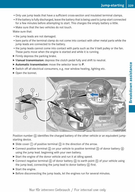
ROnly use jump leads that have a sufficient cross-section and insulated terminal clamps.RIf the battery is fully discharged, leave the battery that is being used to jump-start connected
for a few minutes before attempting to start. This charges the empty battery a little.RMake sure that the two vehicles do not touch.Make sure that:Rthe jump leads are not damaged.Rbare parts of the terminal clamp do not come into contact with other metal parts while the
jump leads are connected to the battery.Rthe jump leads cannot come into contact with parts such as the V-belt pulley or the fan.
These parts move when the engine is started and while it is running.X Firmly depress the parking brake.X Manual transmission: depress the clutch pedal fully and shift to neutral.X Automatic transmission: move the selector lever to P.X Switch off all electrical consumers, e.g. rear window heating, lighting etc.X Open the bonnet.
Position number B identifies the charged battery of the other vehicle or an equivalent jump-starting device.X Slide cover : of positive terminal ; in the direction of the arrow.X Connect positive terminal ; on your vehicle to positive terminal = of donor battery B
using the jump lead. beginning with your own battery.X Start the engine of the donor vehicle and run it at idling speed.X Connect negative terminal ? of donor battery B to earth point A of your vehicle using
the jump lead, connecting the jump lead to donor battery B first.X Start the engine.X Before disconnecting the jump leads, let the engines run for several minutes.
Jump-starting 339
Brea
kdow
n as
sist
ance
Z
X First, remove the jump leads from earth point A and negative terminal ?, then from pos-itive clamp ; and positive terminal =. Begin each time at the contacts on your own vehiclefirst.
X Close cover : of positive clamp ; after removing the jump leads.X Have the battery checked at a qualified specialist workshop.
i Jump-starting is not considered to be a normal operating condition.
i Jump-starting cables and further information regarding jump starting can be obtained atany qualified specialist workshop.
Towing and tow-starting
Important safety notesObserve the legal requirements for the rele-vant countries when towing and tow-starting.
G WARNINGIf the steering wheel lock is engaged, the vehi-cle can no longer be steered. There is a riskof an accident.Always switch on the ignition when towingwith a tow rope or a towing bar.
G WARNINGIf the weight of the vehicle to be towed or tow-started is greater than the permissible grossweight of your vehicle:Rthe towing eye could detach itselfRthe vehicle/trailer combination could over-
turn.There is a risk of an accident.When towing or tow-starting another vehicle,its weight should not be greater than the per-missible gross weight of your vehicle.
Information on your vehicle's gross vehicleweight rating can be found on the vehicleidentification plate (Y page 372).
! If DISTRONIC PLUS or the HOLD functionis activated, the vehicle brakes automati-cally in certain situations. To prevent dam-age to the vehicle, deactivate DISTRONICPLUS and the HOLD function in the follow-ing or other similar situations:Rwhen towing the vehicleRin the car wash
! You may tow the vehicle for a maximumof 50km. A towing speed of 50 km/h mustnot be exceeded.For towing distances over 50 km, the entirevehicle must be lifted up and transported.
! Only secure the tow rope or towing bar tothe towing eyes. The vehicle may otherwisebe damaged.
! Do not use the towing eyes for recoverypurposes as this could damage the vehicle.If in doubt, recover the vehicle with a crane.
! Pull away smoothly when towing away ortow-starting a vehicle. If the tractive poweris too high, the vehicles could be damaged.
! On vehicles with KEYLESS-GO, use thekey instead of the Start/Stop button. Turnthe key to position 2 in the ignition lock andshift the automatic transmission to N.Then, turn the key back to 0 and leave it inthe ignition lock.
It is better to have the vehicle transportedthan to have it towed.
340 Towing and tow-startingBr
eakd
own
assi
stan
ce
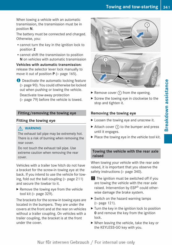
When towing a vehicle with an automatictransmission, the transmission must be inposition N.The battery must be connected and charged.Otherwise, you:Rcannot turn the key in the ignition lock to
position 2Rcannot shift the transmission to position
N on vehicles with automatic transmissionVehicles with automatic transmission:release the selector lever lock manually tomove it out of position P (Y page 165).
i Deactivate the automatic locking feature(Y page 90). You could otherwise be lockedout when pushing or towing the vehicle.Deactivate tow-away protection(Y page 79) before the vehicle is towed.
Fitting/removing the towing eye
Fitting the towing eye
G WARNINGThe exhaust tail pipe may be extremely hot.There is a risk of burning when removing therear cover.Do not touch the exhaust tail pipe. Useextreme caution when removing the rearcover.
Vehicles with a trailer tow hitch do not havea bracket for the screw-in towing eye at theback. If you intend to use the vehicle for tow-ing, fold out the ball coupling (Y page 211)and secure the towbar to it.X Remove the towing eye from the vehicle
tool kit (Y page 329).The brackets for the screw-in towing eyes arelocated in the bumpers. They are under thecovers at the front and at the rear on vehicleswithout a trailer coupling. On vehicles with atrailer coupling, the bracket is at the frontunder the cover.
X Remove cover : from the opening.X Screw the towing eye in clockwise to the
stop and tighten it.
Removing the towing eyeX Loosen the towing eye and unscrew it.X Attach cover : to the bumper and press
until it engages.X Place the towing eye in the vehicle tool kit.
Towing the vehicle with the rear axleraised
When towing your vehicle with the rear axleraised, it is important that you observe thesafety instructions (Y page 340).
! The ignition must be switched off if youare towing the vehicle with the rear axleraised. Intervention by ESP® could other-wise damage the brake system.
X Switch on the hazard warning lamps(Y page 121).
X Turn the key in the ignition lock to position0 and remove the key from the ignitionlock.
X When leaving the vehicle, take the key orthe KEYLESS-GO key with you.
Towing and tow-starting 341
Brea
kdow
n as
sist
ance
Z
Towing the vehicle with both axles onthe ground
It is important that you observe the safetyinstructions when towing away your vehicle(Y page 340).X Switch on the hazard warning lamps
(Y page 121).i When towing with the hazard warning
lamps switched on, use the combinationswitch as usual to signal a change of direc-tion. In this case, only the turn signals forthe desired direction flash. When you resetthe combination switch, the hazard warn-ing lamps start flashing again.
X Turn the key to position 2 in the ignitionlock.
X When the vehicle is stationary, depress thebrake pedal and keep it depressed.
X Vehicles with manual transmission:depress the clutch pedal fully and shift toneutral.
orX Vehicles with automatic transmission:
shift the automatic transmission to posi-tion N.
X Release the brake pedal.X Release the parking brake.
Transporting the vehicleThe towing eyes or trailer tow hitch can beused to pull the vehicle onto a trailer or trans-porter if you wish to transport it.X Vehicles with manual transmission:
depress the clutch pedal fully and shift toneutral.
X Vehicles with automatic transmission:turn the key to position 2 in the ignitionlock.
X Move the selector lever to N.
As soon as the vehicle is loaded:X Prevent the vehicle from rolling away by
applying the parking brake.X Vehicles with manual transmission:
depress the clutch pedal fully and engagefirst or reverse gear.
X Vehicles with automatic transmission:move the selector lever to P.
X Turn the key in the ignition lock to position0 and remove the key from the ignitionlock.
X Secure the vehicle.
! You may only secure the vehicle by thewheels, not by parts of the vehicle such asaxle or steering components. Otherwise,the vehicle could be damaged.
Tow-starting (emergency enginestarting)
When tow-starting, it is important that youobserve the safety notes (Y page 340) and thelegal requirements in each respective coun-try.
! Vehicles with automatic transmissionmust not be tow-started. The transmissionmay otherwise be damaged.
You can find information on "Jump-starting"under (Y page 338).Before tow-starting the following conditionsmust be fulfilled:Rthe battery is connected.Rthe engine has cooled down.Rthe exhaust system has cooled down.X Switch on the hazard warning lamps
(Y page 121).X Fit the towing eye (Y page 341).X Secure the rigid towing bar or the towing
rope.X Depress and hold the brake pedal.X Turn the key to position 2 in the ignition
lock.
342 Towing and tow-startingBr
eakd
own
assi
stan
ce
X Depress the clutch pedal fully, engage sec-ond gear and keep the clutch pedal fullydepressed.
X Release the brake pedal.X Tow-start the vehicle.X Release the clutch pedal slowly; do not
depress the accelerator pedal while doingso.
X When the engine starts, immediatelydepress the clutch pedal fully and shift toneutral.
X Stop at a suitable place, paying attention toroad and traffic conditions.
X Depress the parking brake.X Remove the rigid towing bar or towing rope.X Remove the towing eye (Y page 341).X Switch off the hazard warning lamps.
Electrical fuses
Important safety notes
G WARNINGIf you manipulate, bridge or replace a faultyfuse with a fuse of a higher amperage, theelectric cables could be overloaded. This mayresult in a fire. There is a risk of an accidentand injury.Always replace faulty fuses with specified newfuses of the correct amperage.
! Only use fuses that have been approvedfor Mercedes-Benz vehicles and whichhave the correct fuse rating for the systemconcerned. Otherwise, components or sys-tems could be damaged.
The fuses in your vehicle serve to disconnectfaulty circuits. If a fuse blows, all the compo-nents on the circuit and their functions willfail.Blown fuses must be replaced with fuses ofthe same rating, which you can recognise bythe colour and fuse rating. The fuse ratingsare listed in the fuse allocation chart.
If the newly inserted fuse also blows, have thecause traced and rectified at a qualified spe-cialist workshop, e.g. a Mercedes-BenzService Centre.
Before replacing a fuseX Secure the vehicle against rolling away
(Y page 169).X Switch off all electrical consumers.X Turn the key to position 0 in the ignition
lock and remove it (Y page 149).orX On vehicles with KEYLESS-GO, make sure
the ignition is switched off (Y page 149).All indicator lamps in the instrument clustermust be off.The fuses are located in various fuse boxes:Rfuse box in the engine compartment on the
left-hand side of the vehicle, when viewedin the direction of travelRfuse box in the boot on the right-hand side
of the vehicle, when viewed in the directionof travel
The fuse allocation chart is located in thevehicle tool kit in the stowage compartmentunder the boot floor (Y page 329).
Fuse box in the engine compartment
G WARNINGWhen the bonnet is open, and the windscreenwipers are set in motion, you can be injuredby the wiper linkage. There is a risk of injury.Always switch off the windscreen wipers andthe ignition before opening the bonnet.
! Make sure that no moisture can enter thefuse box when the cover is open.
! When closing the cover, make sure that itis lying correctly on the fuse box. Moistureseeping in or dirt could otherwise impairthe operation of the fuses.
Electrical fuses 343
Brea
kdow
n as
sist
ance
Z
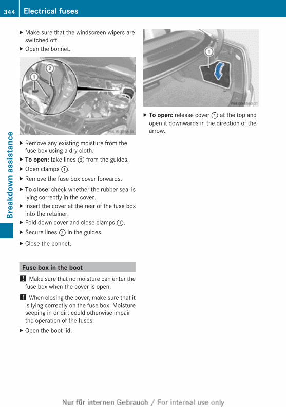
X Make sure that the windscreen wipers areswitched off.
X Open the bonnet.
X Remove any existing moisture from thefuse box using a dry cloth.
X To open: take lines ; from the guides.X Open clamps :.X Remove the fuse box cover forwards.X To close: check whether the rubber seal is
lying correctly in the cover.X Insert the cover at the rear of the fuse box
into the retainer.X Fold down cover and close clamps :.X Secure lines ; in the guides.
X Close the bonnet.
Fuse box in the boot! Make sure that no moisture can enter the
fuse box when the cover is open.
! When closing the cover, make sure that itis lying correctly on the fuse box. Moistureseeping in or dirt could otherwise impairthe operation of the fuses.
X Open the boot lid.
X To open: release cover : at the top andopen it downwards in the direction of thearrow.
344 Electrical fusesBr
eakd
own
assi
stan
ce
Useful information ............................ 346Important safety notes .................... 346Operation ........................................... 347Winter operation ............................... 348Tyre pressure .................................... 350Changing a wheel ............................. 356Fitting a wheel .................................. 357Wheel and tyre combinations .......... 361Emergency spare wheel ................... 365
345
Whe
els
and
tyre
s
Useful information
i This Owner's Manual describes all mod-els, series and optional equipment for yourvehicle that were available at the time ofgoing to press. National variations are pos-sible. Note that your vehicle may not beequipped with all of the functions descri-bed. This is also the case for systems andfunctions relevant to safety.
i Read the information on qualified special-ist workshops: (Y page 28).
Important safety notes
G WARNINGIf wheels and tyres of the wrong size are used,the wheel brakes or suspension componentsmay be damaged. There is a risk of an acci-dent.Always replace wheels and tyres with thosethat fulfil the specifications of the originalpart.When replacing wheels, make sure to fit thecorrect:RdesignationRtypeWhen replacing tyres, make sure to fit thecorrect:RdesignationRmanufacturerRtype
G WARNINGA flat tyre severely impairs the driving, steer-ing and braking characteristics of the vehicle.There is a risk of accident.Tyres without run-flat characteristics:Rdo not drive with a flat tyre.Rimmediately replace the flat tyre with your
emergency spare wheel or spare wheel, orconsult a qualified specialist workshop.
Tyres with run-flat characteristics:Rpay attention to the information and warn-
ing notices on MOExtended tyres (tyreswith run-flat characteristics).
Accessories that are not approved for yourvehicle by Mercedes-Benz or that are notbeing used correctly can impair operatingsafety.Before purchasing and using non-approvedaccessories, visit a qualified specialist work-shop and enquire about:RsuitabilityRlegal stipulationsRfactory recommendationsInformation on the dimensions and types ofwheels and tyres for your vehicle can befound in the "Wheel/tyre combinations" sec-tion (Y page 361).Information on air pressure for the tyres onyour vehicle can be found:Ron the tyre pressure label on the fuel filler
flapRin the "Tyre pressure" sectionModification work on the brake system andwheels is not permitted, nor is the use ofspacer plates or brake dust shields. This inva-lidates the general operating permit for thevehicle.Modification work on the brake system andwheels is not permitted. The use of wheelspacers or brake dust shields is not permit-ted. This invalidates the general operatingpermit for the vehicle.
i Further information on wheels and tyrescan be obtained at any qualified specialistworkshop.
346 Important safety notesW
heel
s an
d ty
res
Operation
Information on drivingRCheck the tyre pressures when the vehicle
is heavily laden and, if necessary, adjust.RWhile driving, pay attention to vibrations,
noises and unusual handling characteris-tics, e.g. pulling to one side. This may indi-cate that the wheels or tyres are damaged.If you suspect that a tyre is defective,reduce your speed immediately. Stop thevehicle as soon as possible to check thewheels and tyres for damage. Hidden tyredamage could also be causing the unusualhandling characteristics. If you find nosigns of damage, have the tyres and wheelschecked at a qualified specialist workshop.RWhen parking your vehicle, make sure that
the tyres do not get deformed by the kerbor other obstacles. If it is necessary to driveover kerbs, speed humps or similar eleva-tions, try to do so at an obtuse angle. Oth-erwise, the tyres, particularly the sidewalls,can get damaged.
Regular checking of wheels and tyres
G WARNINGDamaged tyres can cause tyre inflation pres-sure loss. As a result, you could lose controlof your vehicle. There is a risk of accident.Check the tyres regularly for signs of damageand replace any damaged tyres immediately.
RRegularly check the wheels and tyres ofyour vehicle for damage at least once amonth, as well as after driving off-road oron rough roads. Damaged wheels can
cause a loss of tyre pressure. Pay particularattention to damage such as:- cuts in the tyres- punctures- tears in the tyres- bulges on tyres- deformation or severe corrosion on
wheelsRRegularly check the tyre tread depth and
the condition of the tread across the wholewidth of the tyre (Y page 347). If neces-sary, turn the front wheels to full lock inorder to inspect the inner side of the tyresurface.RAll wheels must have a valve cap to protect
the valve against dirt and moisture. Do notfit anything onto the valve other than thestandard valve cap or other valve capsapproved by Mercedes-Benz for your vehi-cle. Do not fit any other valve caps or sys-tems, e.g. tyre pressure monitoring sys-tems.RRegularly check the pressure of all the tyres
including the emergency spare wheel or thespare wheel, particularly prior to long trips,and correct the pressure as necessary(Y page 350).
Observe the notes on the emergency sparewheel (Y page 365).The service life of tyres depends on variousfactors, including the following:RDriving styleRTyre pressureRMileage
Important safety notes on the tyretread
G WARNINGInsufficient tyre tread will reduce tyre trac-tion. The tyre is no longer able to dissipatewater. This means that on wet road surfaces,the risk of aquaplaning increases, in particular
Operation 347
Whe
els
and
tyre
s
Z
where speed is not adapted to suit the drivingconditions. There is a risk of accident.If the tyre pressure is too high or too low, tyresmay exhibit different levels of wear at differ-ent locations on the tyre tread. Thus, youshould regularly check the tread depth andthe condition of the tread across the entirewidth of all tyres.Minimum tyre tread depth for:Rsummer tyres: 3 mmRM+S tyres: 4 mmFor safety reasons, replace the tyres beforethe legally prescribed limit for the minimumtyre tread depth is reached..
Selecting, fitting and replacing tyresROnly fit tyres and wheels of the same type
and make.Exception: it is permissible to fit a differenttype or make in the event of a flat tyre.Observe the "MOExtended tyres (tyres withrun-flat characteristics)" section(Y page 330).ROnly fit tyres of the correct size onto the
wheels.RAfter fitting new tyres, run them in at mod-
erate speeds for the first 100 km, as theyonly reach their full performance after thisdistance.RDo not drive with tyres which have too little
tread depth, as this significantly reducesthe traction on wet roads (aquaplaning).RReplace the tyres after six years at the lat-
est, regardless of wear.Observe the notes on the emergency sparewheel (Y page 365).
MOExtended tyres (tyres with run-flatcharacteristics)
With MOExtended tyres (tyres with run-flatcharacteristics), you can continue to drive
your vehicle even if there is a total loss ofpressure in one or more tyres.Only use MOExtended tyres in conjunctionwith an activated tyre pressure loss warningsystem or tyre pressure monitoring systemand only on tyres specifically inspected byMercedes-Benz.
i Vehicles with MOExtended tyres are notequipped with a TIREFIT kit at the factory.It is therefore recommended that you addi-tionally equip your vehicle with a TIREFIT kitif you fit tyres that do not feature run-flatcharacteristics, e.g. winter tyres. A TIREFITkit can be obtained from a qualified spe-cialist workshop.
Notes on driving with MOExtended tyres inthe event of a flat tyre can be found in the"Breakdown assistance" section(Y page 330).
Winter operation
Points to rememberHave your vehicle winterproofed at a qualifiedspecialist workshop at the onset of winter.Observe the notes in the "Changing a wheel"section (Y page 356).
Driving with summer tyresAt temperatures below +7 †, summer tyreslose elasticity and therefore traction andbraking power. Change the tyres on your vehi-cle to M+S tyres. Using summer tyres at verycold temperatures could cause tears to form,thereby damaging the tyres permanently.Mercedes-Benz cannot accept responsibilityfor this type of damage.
M+S tyres
G WARNINGM+S tyres with a tyre tread depth of less than4 mm are not suitable for use in winter as they
348 Winter operationW
heel
s an
d ty
res
do not provide sufficient traction. There is arisk of accident.M+S tyres with a tread depth of less than4 mm must be replaced.
At temperatures below +7 †, use winter tyresor all-season tyres. Both types of tyre areidentified by the M+S marking.Only winter tyres bearing the i snowflakesymbol in addition to the M+S marking pro-vide the best possible grip in wintry road con-ditions. Only these tyres will allow drivingsafety systems such as ABS and ESP® tofunction optimally in winter. These tyres havebeen developed specifically for driving insnow.Use M+S tyres of the same make and treadon all wheels to maintain safe handling char-acteristics.Always observe the maximum permissiblespeed specified for the M+S tyres you havefitted.If you fit M+S tyres that have a lower maxi-mum permissible speed than that of the vehi-cle, affix an appropriate warning sign in thedriver's field of vision. This can be obtainedat a qualified specialist workshop.Under these circumstances, you should alsorestrict the maximum speed of the vehicleusing permanent SPEEDTRONIC so that itdoes not exceed the maximum permissiblespeed for the M+S tyres(Y page 179).If you have fitted M+S tyres:X Check the tyre pressures (Y page 350).X Restart the tyre pressure loss warning sys-
tem (Y page 351).X Restart the tyre pressure monitor
(Y page 355).For more information on driving with theemergency spare wheel, see (Y page 365).
Snow chains
G WARNINGIf you have fitted snow chains to the frontwheels, they may scrape against the vehiclebody or chassis components. This couldcause damage to the vehicle or the tyres.There is a risk of an accident.To avoid hazardous situations:Rnever fit snow chains on the front wheelsRfit snow chains to the rear wheels in pairs.
! Vehicles with steel wheels: if you wishto fit snow chains to steel wheels, makesure that you remove the respectivewheels' hubcaps first. The hubcaps mayotherwise be damaged.
For safety reasons, Mercedes-Benz recom-mends that you only use snow chains thathave been specially approved for your vehicleby Mercedes-Benz, or that are of a corre-sponding standard of quality.If you intend to fit snow chains, please bearthe following points in mind:Rsnow chains cannot be fitted to all wheel-
tyre combinations. Permissible wheel-tyrecombinations (Y page 361).Ronly use snow chains when the road sur-
face is completely snow-covered. Removethe snow chains as soon as possible whenyou come to a road that is not snow-cov-ered.Rlocal regulations may restrict the use of
snow chains. Observe the appropriate reg-ulations if you wish to fit snow chains.Rdo not exceed the maximum permissible
speed of 50 km/h.
i You may wish to deactivateESP®(Y page 73) when pulling away withsnow chains fitted. This way you can allowthe wheels to spin in a controlled manner,achieving an increased driving force (cut-ting action).
For more information on driving with theemergency spare wheel, see (Y page 365).
Winter operation 349
Whe
els
and
tyre
s
Z
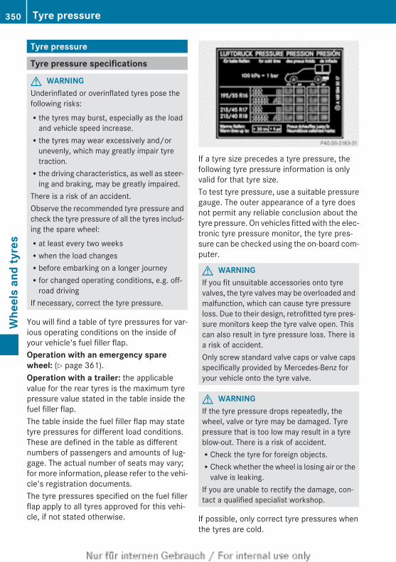
Tyre pressure
Tyre pressure specifications
G WARNINGUnderinflated or overinflated tyres pose thefollowing risks:Rthe tyres may burst, especially as the load
and vehicle speed increase.Rthe tyres may wear excessively and/or
unevenly, which may greatly impair tyretraction.Rthe driving characteristics, as well as steer-
ing and braking, may be greatly impaired.There is a risk of an accident.Observe the recommended tyre pressure andcheck the tyre pressure of all the tyres includ-ing the spare wheel:Rat least every two weeksRwhen the load changesRbefore embarking on a longer journeyRfor changed operating conditions, e.g. off-
road drivingIf necessary, correct the tyre pressure.
You will find a table of tyre pressures for var-ious operating conditions on the inside ofyour vehicle's fuel filler flap.Operation with an emergency spare wheel: (Y page 361).Operation with a trailer: the applicablevalue for the rear tyres is the maximum tyrepressure value stated in the table inside thefuel filler flap.The table inside the fuel filler flap may statetyre pressures for different load conditions.These are defined in the table as differentnumbers of passengers and amounts of lug-gage. The actual number of seats may vary;for more information, please refer to the vehi-cle's registration documents.The tyre pressures specified on the fuel fillerflap apply to all tyres approved for this vehi-cle, if not stated otherwise.
If a tyre size precedes a tyre pressure, thefollowing tyre pressure information is onlyvalid for that tyre size.To test tyre pressure, use a suitable pressuregauge. The outer appearance of a tyre doesnot permit any reliable conclusion about thetyre pressure. On vehicles fitted with the elec-tronic tyre pressure monitor, the tyre pres-sure can be checked using the on-board com-puter.
G WARNINGIf you fit unsuitable accessories onto tyrevalves, the tyre valves may be overloaded andmalfunction, which can cause tyre pressureloss. Due to their design, retrofitted tyre pres-sure monitors keep the tyre valve open. Thiscan also result in tyre pressure loss. There isa risk of accident.Only screw standard valve caps or valve capsspecifically provided by Mercedes-Benz foryour vehicle onto the tyre valve.
G WARNINGIf the tyre pressure drops repeatedly, thewheel, valve or tyre may be damaged. Tyrepressure that is too low may result in a tyreblow-out. There is a risk of accident.RCheck the tyre for foreign objects.RCheck whether the wheel is losing air or the
valve is leaking.If you are unable to rectify the damage, con-tact a qualified specialist workshop.
If possible, only correct tyre pressures whenthe tyres are cold.
350 Tyre pressureW
heel
s an
d ty
res
The tyres are cold:Rif the vehicle has been parked with the tyres
out of direct sunlight for at least threehours andRif the vehicle has not been driven further
than 1.6 kmDepending on the ambient temperature, thespeed at which you are driving and the loadon the tyres, the tyre temperature and thusthe tyre pressure change by approximately10 kPa per 10 † (0.1 bar/1.5 psi). Take thisinto account when checking the pressure ofwarm tyres and only correct it if it is too lowfor the current operating conditions.Driving with tyre pressure that is too high ortoo low can:Rshorten the service life of the tyresRcause increased tyre damageRhave a negative effect on handling charac-
teristics and thus the driving safety (e.g.aquaplaning)
i The tyre pressure values given for lowloads are minimum values which offer yougood ride comfort characteristics.However, you can also use the values givenfor higher loads. These are permissible andwill not adversely affect the running of thevehicle.
The values on the tyre pressure informationlabel (fuel filler flap) for the vehicle in "parti-ally laden" and "fully laden" conditions applywhen driving at maximum speed. Despite thevalues stated on the tyre pressure informa-tion label, for the vehicle with "partially laden up to 210 km/h" status, the valuescan be reduced as follows, without a reduc-tion in safety:RÒ30 kPa (Ò0.3 bar/Ò4 psi) for all modelsThis does not apply to vehicles towing atrailer.This improves the ride comfort of your vehi-cle; however, the fuel consumption mayincrease slightly.
H Environmental noteCheck the tyre pressure regularly, at leastevery 14 days.
Tyre pressure loss warning system
General notesWhile the vehicle is in motion, the tyre pres-sure loss warning system monitors the settyre pressure using the rotational speed ofthe wheels. This enables the system to detectsignificant pressure loss in a tyre. If the speedof rotation of a wheel changes as a result ofa loss of pressure, a corresponding warningmessage will appear in the multifunction dis-play.You can recognise the tyre pressure losswarning by the Run Flat Indicator active Restart with OK message whichappears in the Service menu of the multi-function display. Information on the messagedisplay can be found in the "Restarting thetyre pressure loss warning system" section(Y page 352).
Important safety notesThe tyre pressure warning system does notwarn you of an incorrectly set tyre pressure.Observe the notes on the recommended tyrepressure (Y page 350).The tyre pressure loss warning does notreplace the need to regularly check the tyrepressures. An even loss of pressure on sev-eral tyres at the same time cannot be detec-ted by the tyre pressure loss warning system.The tyre pressure monitor is not able to warnyou of a sudden loss of pressure, e.g. if thetyre is penetrated by a foreign object. In theevent of a sudden loss of pressure, bring thevehicle to a halt by braking carefully. Avoidabrupt steering manoeuvres.
Tyre pressure 351
Whe
els
and
tyre
s
Z
The function of the tyre pressure loss warningsystem is limited or delayed if:Rsnow chains are fitted to your vehicle's
tyres.Rroad conditions are wintry.Ryou are driving on sand or gravel.Ryou adopt a very sporty driving style (cor-
nering at high speeds or driving with highrates of acceleration).Ryou are towing a very heavy or large trailer.Ryou are driving with a heavy load (in the
vehicle or on the roof).
Restarting the tyre pressure loss warn-ing systemRestart the tyre pressure loss warning systemif you have:Rchanged the tyre pressureRchanged the wheels or tyresRfitted new wheels or tyresX Before restarting, consult the table of tyre
pressures on the inside of the fuel filler flapto ensure that the tyre pressure in all fourtyres is set correctly for the respectiveoperating conditions.The tyre pressure loss warning system canonly give reliable warnings if you have setthe correct tyre pressure. If an incorrecttyre pressure is set, these incorrect valueswill be monitored.
X Observe the notes in the section on tyrepressures (Y page 350).
Restarting using the 4-button multifunc-tion steering wheelX Make sure that the key is in position 2 in
the ignition lock.X Press the V button to select Tyre pressure Menu: R.
X Press the C button.The RFI active Restart: R messageappears in the multifunction display.
X Press the C button.The Tyre press. OK? message appears inthe multifunction display.
If you wish to confirm the restart:X Press the W button.
The Run Flat Indicator restartedmessage appears in the multifunction dis-play.After a teach-in period, the tyre pressureloss warning system will monitor the settyre pressures of all four tyres.
orIf you wish to cancel the restart:X Press the X button.
The tyre pressure values stored at the lastrestart will continue to be monitored.
Restarting using the 12-button multifunc-tion steering wheelX Make sure that the key is in position 2 in
the ignition lock.X Press the = or ; button to select theService menu.
X Press the 9 or : button to selectTyre pressure.
X Press the a button.The Run Flat Indicator active Restart with OK message appears in themultifunction display.
If you wish to confirm the restart:X Press the a button.
The Tyre pressure now OK? messageappears in the multifunction display.
X Press the 9 or : button to selectYes.
X Press the a button.The Run Flat Indicator restartedmessage appears in the multifunction dis-play.
352 Tyre pressureW
heel
s an
d ty
res
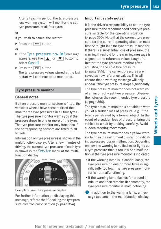
After a teach-in period, the tyre pressureloss warning system will monitor the settyre pressures of all four tyres.
orIf you wish to cancel the restart:X Press the % button.orX If the Tyre pressure now OK? message
appears, use the 9 or : button toselect Cancel.
X Press the a button.The tyre pressure values stored at the lastrestart will continue to be monitored.
Tyre pressure monitor
General notesIf a tyre pressure monitor system is fitted, thevehicle's wheels have sensors fitted thatmonitor the tyre pressures in all four tyres.The tyre pressure monitor warns you if thepressure drops in one or more of the tyres.The tyre pressure monitor only functions ifthe corresponding sensors are fitted to allwheels.Information on tyre pressures is shown in themultifunction display. After a few minutes ofdriving, the current tyre pressure of each tyreis shown in the Service menu of the multi-function display.
Example: current tyre pressure display
For further information on displaying thismessage, refer to the "Checking the tyre pres-sure electronically" section (Y page 354).
Important safety notesIt is the driver's responsibility to set the tyrepressure to the recommended cold tyre pres-sure suitable for the operating situation(Y page 350). Note that the correct tyre pres-sure for the current operating situation mustfirst be taught-in to the tyre pressure monitor.If there is a substantial loss of pressure, thewarning threshold for the warning message isaligned to the reference values taught-in.Restart the tyre pressure monitor afteradjusting to the cold tyre pressure(Y page 355). The current pressures aresaved as new reference values. This willensure that a warning message will onlyappear if the tyre pressure drops significantly.The tyre pressure monitor does not warn youof an incorrectly set tyre pressure. Observethe notes on the recommended tyre pressure(Y page 350).The tyre pressure monitor is not able to warnyou of a sudden loss of pressure, e.g. if thetyre is penetrated by a foreign object. In theevent of a sudden loss of pressure, bring thevehicle to a halt by braking carefully. Avoidsudden steering movements.The tyre pressure monitor has a yellow warn-ing lamp in the instrument cluster for indicat-ing a pressure loss or malfunction. Dependingon how the warning lamp flashes or lights up,a tyre pressure that is too low or a malfunc-tion in the tyre pressure monitor is indicated:Rif the warning lamp is lit continuously, the
tyre pressure on one or more tyres is sig-nificantly too low. The tyre pressure moni-tor is not malfunctioning.Rif the warning lamp flashes for around a
minute and then remains lit constantly, thetyre pressure monitor is malfunctioning.
i In addition to the warning lamp, a mes-sage appears in the multifunction display.
Tyre pressure 353
Whe
els
and
tyre
s
Z
Further information can be found on:RVehicles with a 4-button multifunction
steering wheel: (Y page 270).RVehicles with a 12-button multifunction
steering wheel: (Y page 271).If the tyre pressure monitor is malfunctioning,it may take more than ten minutes for the tyrepressure warning lamp to inform you of themalfunction by flashing for approximately oneminute and then remaining lit. When the faulthas been rectified, the tyre pressure warninglamp goes out after you have driven for a fewminutes.The tyre pressure values indicated by the on-board computer may differ from those meas-ured at a filling station using a pressuregauge. The tyre pressures shown by the on-board computer refer to those measured atsea level. At high altitudes, the tyre pressurevalues indicated by a pressure gauge arehigher than those shown by the on-boardcomputer. In this case, do not reduce the tyrepressures.The operation of the tyre pressure monitorcan be affected by interference from radiotransmitting equipment (e.g. radio head-phones, two-way radios) that may be beingoperated in or near the vehicle.
Checking the tyre pressure electroni-callyX Make sure that the key is in position 2 in
the ignition lock (Y page 149).X Press the = or ; button on the steer-
ing wheel to select the Service menu.X Press the 9 or : button to selectTyre pressure.
X Press the a button.The current tyre pressure for each wheelwill be displayed in the multifunction dis-play.
If the vehicle has been parked for over20 minutes, the Tyre pressures will be displayed after a few minutes of driving message appears.
After a teach-in period, the tyre pressuremonitor automatically recognises newwheels or new sensors. As long as a clearallocation of the tyre pressure values to theindividual wheels is not possible, the Tyre pressure monitor active display mes-sage is shown instead of the tyre pressuredisplay. The tyre pressures are already beingmonitored.
i If a spare wheel/emergency spare wheelis fitted, for a few minutes the system maycontinue to show the tyre pressure of thewheel that has been removed. If thisoccurs, the value displayed for the positionwhere the spare wheel/emergency sparewheel is fitted is not the same as the sparewheel/emergency spare wheel's currenttyre pressure.
Warning messages of the tyre pressuremonitorIf the tyre pressure monitor detects a pres-sure loss in one or more tyres, a warning mes-sage is shown in the multifunction display andthe yellow tyre pressure monitor warning lightcomes on.RIf the Please correct tyre pressure
message appears in the multifunction dis-play, the tyre pressure in at least one tyreis too low and must be corrected at the nextopportunity.RIf the Check tyre(s) message appears in
the multifunction display, the tyre pressurein one or more tyres has dropped signifi-cantly and the tyres must be checked.RIf the Tyre malfunction appears in the
multifunction display, the tyre pressure inone or more tyres has dropped suddenlyand the tyres must be checked.
Observe the instructions and safety notes inthe display messages in the "Tyres" section(Y page 271).
i If the wheel positions on the vehicle areinterchanged, the tyre pressures may bedisplayed for the wrong positions for a
354 Tyre pressureW
heel
s an
d ty
res
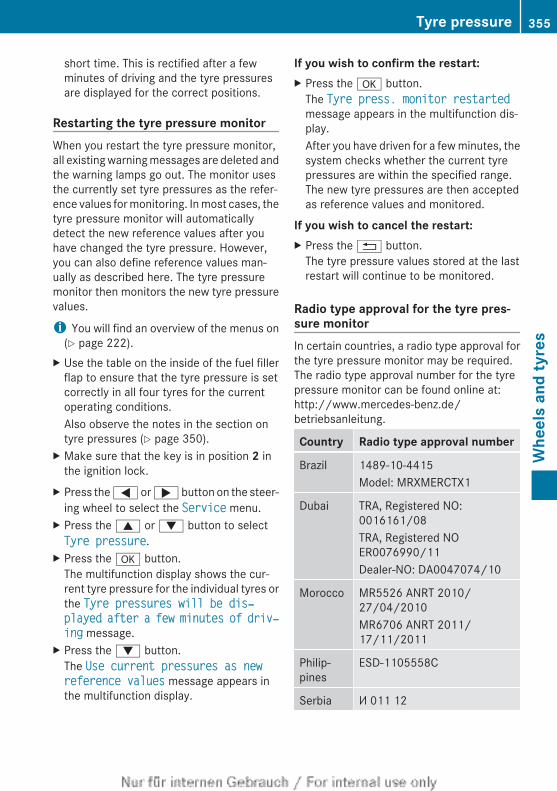
short time. This is rectified after a fewminutes of driving and the tyre pressuresare displayed for the correct positions.
Restarting the tyre pressure monitorWhen you restart the tyre pressure monitor,all existing warning messages are deleted andthe warning lamps go out. The monitor usesthe currently set tyre pressures as the refer-ence values for monitoring. In most cases, thetyre pressure monitor will automaticallydetect the new reference values after youhave changed the tyre pressure. However,you can also define reference values man-ually as described here. The tyre pressuremonitor then monitors the new tyre pressurevalues.
i You will find an overview of the menus on(Y page 222).
X Use the table on the inside of the fuel fillerflap to ensure that the tyre pressure is setcorrectly in all four tyres for the currentoperating conditions.Also observe the notes in the section ontyre pressures (Y page 350).
X Make sure that the key is in position 2 inthe ignition lock.
X Press the = or ; button on the steer-ing wheel to select the Service menu.
X Press the 9 or : button to selectTyre pressure.
X Press the a button.The multifunction display shows the cur-rent tyre pressure for the individual tyres orthe Tyre pressures will be dis‐played after a few minutes of driv‐ing message.
X Press the : button.The Use current pressures as new reference values message appears inthe multifunction display.
If you wish to confirm the restart:X Press the a button.
The Tyre press. monitor restartedmessage appears in the multifunction dis-play.After you have driven for a few minutes, thesystem checks whether the current tyrepressures are within the specified range.The new tyre pressures are then acceptedas reference values and monitored.
If you wish to cancel the restart:X Press the % button.
The tyre pressure values stored at the lastrestart will continue to be monitored.
Radio type approval for the tyre pres-sure monitorIn certain countries, a radio type approval forthe tyre pressure monitor may be required.The radio type approval number for the tyrepressure monitor can be found online at:http://www.mercedes-benz.de/betriebsanleitung.
Country Radio type approval number
Brazil 1489-10-4415Model: MRXMERCTX1
Dubai TRA, Registered NO:0016161/08TRA, Registered NOER0076990/11Dealer-NO: DA0047074/10
Morocco MR5526 ANRT 2010/27/04/2010MR6706 ANRT 2011/17/11/2011
Philip-pines
ESD-1105558C
Serbia И 011 12
Tyre pressure 355
Whe
els
and
tyre
s
Z
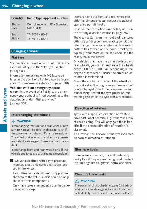
Country Radio type approval number
Singa-pore
Compliance with IDA StandardN0140-09
SouthAfrica
TA-2008/1068TA-2011/1370
Changing a wheel
Flat tyreYou can find information on what to do in theevent of flat tyre in the "Flat tyre" section(Y page 330).Information on driving with MOExtendedtyres in the event of a flat tyre can be foundunder "Breakdown assistance" (Y page 330).Vehicles with an emergency spare wheel: in the event of a flat tyre, the emer-gency spare wheel is fitted according to thedescription under "Fitting a wheel"(Y page 357).
Interchanging the wheels
G WARNINGInterchanging the front and rear wheels mayseverely impair the driving characteristics ifthe wheels or tyres have different dimensions.The wheel brakes or suspension componentsmay also be damaged. There is a risk of acci-dent.Interchange front and rear wheels only if thewheels and tyres are of the same dimensions.
! On vehicles fitted with a tyre pressuremonitor, electronic components are loca-ted in the wheel.Tyre-fitting tools should not be applied inthe area of the valve, as this could damagethe electronic components.Only have tyres changed at a qualified spe-cialist workshop.
Interchanging the front and rear wheels ofdiffering dimensions can render the generaloperating permit invalid.Observe the instructions and safety notes inthe "Fitting a wheel" section (Y page 357).The wear patterns on the front and rear tyresdiffer, depending on the operating conditions.Interchange the wheels before a clear wearpattern has formed on the tyres. Front tyrestypically wear more on the shoulders and therear tyres in the centre.On vehicles that have the same size front andrear wheels, you can interchange the wheelsevery 5,000 to 10,000 km depending on thedegree of tyre wear. Ensure the direction ofrotation is maintained.Clean the contact surfaces of the wheel andthe brake disc thoroughly every time a wheelis interchanged. Check the tyre pressure and,if necessary, restart the tyre pressure losswarning system or the tyre pressure monitor.
Direction of rotationTyres with a specified direction of rotationhave additional benefits, e.g. if there is a riskof aquaplaning. You will only gain these ben-efits if the correct direction of rotation isobserved.An arrow on the sidewall of the tyre indicatesits correct direction of rotation.
Storing wheelsStore wheels in a cool, dry and preferablydark place if they are not being used. Protectthe tyres against oil, grease, petrol and diesel.
Cleaning the wheels
G WARNINGThe water jet of circular-jet nozzles (dirt grind-ers) can cause damage not visible from theoutside to tyres or chassis components. Com-
356 Changing a wheelW
heel
s an
d ty
res
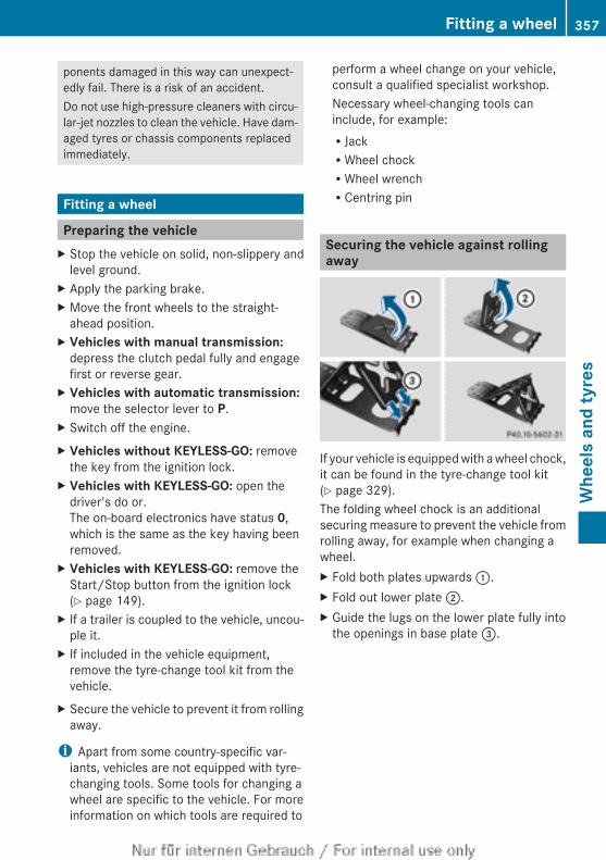
ponents damaged in this way can unexpect-edly fail. There is a risk of an accident.Do not use high-pressure cleaners with circu-lar-jet nozzles to clean the vehicle. Have dam-aged tyres or chassis components replacedimmediately.
Fitting a wheel
Preparing the vehicleX Stop the vehicle on solid, non-slippery and
level ground.X Apply the parking brake.X Move the front wheels to the straight-
ahead position.X Vehicles with manual transmission:
depress the clutch pedal fully and engagefirst or reverse gear.
X Vehicles with automatic transmission:move the selector lever to P.
X Switch off the engine.X Vehicles without KEYLESS-GO: remove
the key from the ignition lock.X Vehicles with KEYLESS-GO: open the
driver's do or.The on-board electronics have status 0,which is the same as the key having beenremoved.
X Vehicles with KEYLESS-GO: remove theStart/Stop button from the ignition lock(Y page 149).
X If a trailer is coupled to the vehicle, uncou-ple it.
X If included in the vehicle equipment,remove the tyre-change tool kit from thevehicle.
X Secure the vehicle to prevent it from rollingaway.
i Apart from some country-specific var-iants, vehicles are not equipped with tyre-changing tools. Some tools for changing awheel are specific to the vehicle. For moreinformation on which tools are required to
perform a wheel change on your vehicle,consult a qualified specialist workshop.Necessary wheel-changing tools caninclude, for example:RJackRWheel chockRWheel wrenchRCentring pin
Securing the vehicle against rollingaway
If your vehicle is equipped with a wheel chock,it can be found in the tyre-change tool kit(Y page 329).The folding wheel chock is an additionalsecuring measure to prevent the vehicle fromrolling away, for example when changing awheel.X Fold both plates upwards :.X Fold out lower plate ;.X Guide the lugs on the lower plate fully into
the openings in base plate =.
Fitting a wheel 357
Whe
els
and
tyre
s
Z
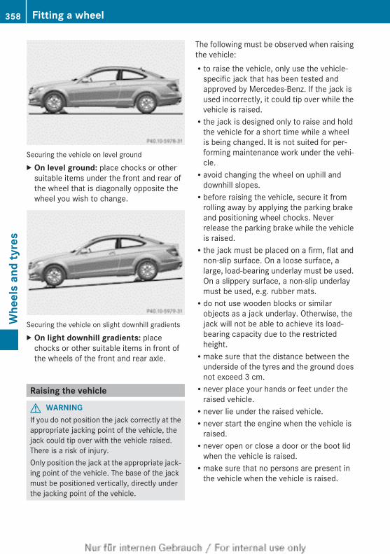
Securing the vehicle on level groundX On level ground: place chocks or other
suitable items under the front and rear ofthe wheel that is diagonally opposite thewheel you wish to change.
Securing the vehicle on slight downhill gradientsX On light downhill gradients: place
chocks or other suitable items in front ofthe wheels of the front and rear axle.
Raising the vehicle
G WARNINGIf you do not position the jack correctly at theappropriate jacking point of the vehicle, thejack could tip over with the vehicle raised.There is a risk of injury.Only position the jack at the appropriate jack-ing point of the vehicle. The base of the jackmust be positioned vertically, directly underthe jacking point of the vehicle.
The following must be observed when raisingthe vehicle:Rto raise the vehicle, only use the vehicle-
specific jack that has been tested andapproved by Mercedes-Benz. If the jack isused incorrectly, it could tip over while thevehicle is raised.Rthe jack is designed only to raise and hold
the vehicle for a short time while a wheelis being changed. It is not suited for per-forming maintenance work under the vehi-cle.Ravoid changing the wheel on uphill and
downhill slopes.Rbefore raising the vehicle, secure it from
rolling away by applying the parking brakeand positioning wheel chocks. Neverrelease the parking brake while the vehicleis raised.Rthe jack must be placed on a firm, flat and
non-slip surface. On a loose surface, alarge, load-bearing underlay must be used.On a slippery surface, a non-slip underlaymust be used, e.g. rubber mats.Rdo not use wooden blocks or similar
objects as a jack underlay. Otherwise, thejack will not be able to achieve its load-bearing capacity due to the restrictedheight.Rmake sure that the distance between the
underside of the tyres and the ground doesnot exceed 3 cm.Rnever place your hands or feet under the
raised vehicle.Rnever lie under the raised vehicle.Rnever start the engine when the vehicle is
raised.Rnever open or close a door or the boot lid
when the vehicle is raised.Rmake sure that no persons are present in
the vehicle when the vehicle is raised.
358 Fitting a wheelW
heel
s an
d ty
res
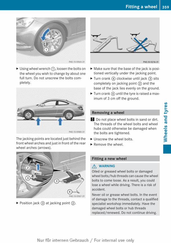
X Using wheel wrench :, loosen the bolts onthe wheel you wish to change by about onefull turn. Do not unscrew the bolts com-pletely.
The jacking points are located just behind thefront wheel arches and just in front of the rearwheel arches (arrows).
X Position jack = at jacking point ;.
X Make sure that the base of the jack is posi-tioned vertically under the jacking point.
X Turn crank ? clockwise until jack = sitscompletely on jacking point ; and thebase of the jack lies evenly on the ground.
X Turn crank ? until the tyre is raised a max-imum of 3 cm off the ground.
Removing a wheel! Do not place wheel bolts in sand or dirt.
The threads of the wheel bolts and wheelhubs could otherwise be damaged whenthe bolts are tightened.
X Unscrew the wheel bolts.X Remove the wheel.
Fitting a new wheel
G WARNINGOiled or greased wheel bolts or damagedwheel bolts/hub threads can cause the wheelbolts to come loose. As a result, you couldlose a wheel while driving. There is a risk ofaccident.Never oil or grease wheel bolts. In the eventof damage to the threads, contact a qualifiedspecialist workshop immediately. Have thedamaged wheel bolts or hub threadsreplaced/renewed. Do not continue driving.
Fitting a wheel 359
Whe
els
and
tyre
s
Z
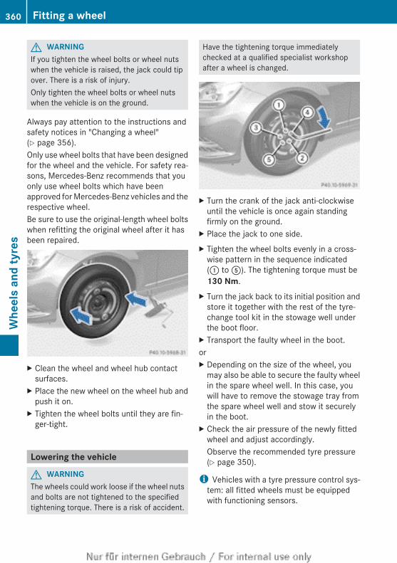
G WARNINGIf you tighten the wheel bolts or wheel nutswhen the vehicle is raised, the jack could tipover. There is a risk of injury.Only tighten the wheel bolts or wheel nutswhen the vehicle is on the ground.
Always pay attention to the instructions andsafety notices in "Changing a wheel"(Y page 356).Only use wheel bolts that have been designedfor the wheel and the vehicle. For safety rea-sons, Mercedes-Benz recommends that youonly use wheel bolts which have beenapproved for Mercedes-Benz vehicles and therespective wheel.Be sure to use the original-length wheel boltswhen refitting the original wheel after it hasbeen repaired.
X Clean the wheel and wheel hub contactsurfaces.
X Place the new wheel on the wheel hub andpush it on.
X Tighten the wheel bolts until they are fin-ger-tight.
Lowering the vehicle
G WARNINGThe wheels could work loose if the wheel nutsand bolts are not tightened to the specifiedtightening torque. There is a risk of accident.
Have the tightening torque immediatelychecked at a qualified specialist workshopafter a wheel is changed.
X Turn the crank of the jack anti-clockwiseuntil the vehicle is once again standingfirmly on the ground.
X Place the jack to one side.X Tighten the wheel bolts evenly in a cross-
wise pattern in the sequence indicated(: to A). The tightening torque must be130 Nm.
X Turn the jack back to its initial position andstore it together with the rest of the tyre-change tool kit in the stowage well underthe boot floor.
X Transport the faulty wheel in the boot.orX Depending on the size of the wheel, you
may also be able to secure the faulty wheelin the spare wheel well. In this case, youwill have to remove the stowage tray fromthe spare wheel well and stow it securelyin the boot.
X Check the air pressure of the newly fittedwheel and adjust accordingly.Observe the recommended tyre pressure(Y page 350).
i Vehicles with a tyre pressure control sys-tem: all fitted wheels must be equippedwith functioning sensors.
360 Fitting a wheelW
heel
s an
d ty
res
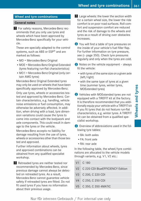
Wheel and tyre combinations
General notes! For safety reasons, Mercedes-Benz rec-
ommends that you only use tyres andwheels which have been approved byMercedes-Benz specifically for your vehi-cle.These are specially adapted to the controlsystems, such as ABS or ESP® and aremarked as follows:RMO = Mercedes-Benz OriginalRMOE = Mercedes-Benz Original Extended
(tyres featuring run-flat characteristics)RMO1 = Mercedes-Benz Original (only cer-
tain AMG tyres)Mercedes-Benz Original Extended tyresmay only be used on wheels that have beenspecifically approved by Mercedes-Benz.Only use tyres, wheels or accessories tes-ted and approved by Mercedes-Benz. Cer-tain characteristics, e.g. handling, vehiclenoise emissions or fuel consumption, mayotherwise be adversely affected. In addi-tion, when driving with a load, tyre dimen-sion variations could cause the tyres tocome into contact with the bodywork andaxle components. This could result in dam-age to the tyres or the vehicle.Mercedes-Benz accepts no liability fordamage resulting from the use of tyres,wheels or accessories other than those tes-ted and approved.Further information about wheels, tyresand approved combinations can beobtained from any qualified specialistworkshop.
! Retreaded tyres are neither tested norrecommended by Mercedes-Benz, sinceprevious damage cannot always be detec-ted on retreaded tyres. As a result,Mercedes-Benz cannot guarantee vehiclesafety if retreaded tyres are fitted. Do notfit used tyres if you have no informationabout their previous usage.
! Large wheels: the lower the section widthfor a certain wheel size, the lower the ridecomfort is on poor road surfaces. Roll com-fort and suspension comfort are reducedand the risk of damage to the wheels andtyres as a result of driving over obstaclesincreases.
i You will find a table of tyre pressures onthe inside of your vehicle's fuel filler flap.For further information on tyre pressure,see (Y page 350). Check tyre pressuresregularly and only when the tyres are cold.
i Notes on the vehicle equipment – alwaysfit the vehicle:Rwith tyres of the same size on a given axle
(left/right)Rwith the same type of tyres at a given
time (summer tyres, winter tyres,MOExtended tyres)
i Vehicles with MOExtended tyres are notequipped with a TIREFIT kit at the factory.It is therefore recommended that you addi-tionally equip your vehicle with a TIREFIT kitif you fit tyres that do not feature run-flatcharacteristics, e.g. winter tyres. A TIREFITkit can be obtained from a qualified spe-cialist workshop.
i Overview of abbreviations used in the fol-lowing tyre tables:RBA: both axlesRFA: front axleRRA: rear axle
In the following table, the wheel/tyre combi-nations are allocated to the vehicle modelsthrough variants, e.g. V1, V2 etc.:
V1 C 180
V2 C 220 CDI BlueEFFICIENCY Edition
V3 C 200, C 220 CDI
V4 C 250, C 250 CDI
V5 C 350, C 350 4MATIC
Wheel and tyre combinations 361
Whe
els
and
tyre
s
Z
V6 C 250 Sport, C 250 CDI Sport
V7 C 63 AMG
i Not all wheel/tyre combinations can befitted at the factory in all countries.
362 Wheel and tyre combinationsW
heel
s an
d ty
res
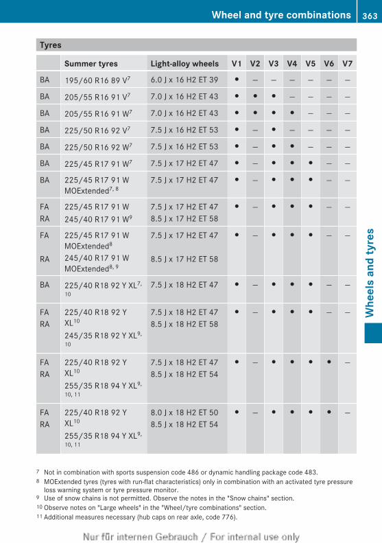
Tyres
Summer tyres Light-alloy wheels V1 V2 V3 V4 V5 V6 V7
BA 195/60 R16 89 V7 6.0 J x 16 H2 ET 39 # — — — — — —
BA 205/55 R16 91 V7 7.0 J x 16 H2 ET 43 # # # — — — —
BA 205/55 R16 91 W7 7.0 J x 16 H2 ET 43 # # # # — — —
BA 225/50 R16 92 V7 7.5 J x 16 H2 ET 53 # — # — — — —
BA 225/50 R16 92 W7 7.5 J x 16 H2 ET 53 # — # # — — —
BA 225/45 R17 91 W7 7.5 J x 17 H2 ET 47 # — # # # — —
BA 225/45 R17 91 WMOExtended7, 8
7.5 J x 17 H2 ET 47 # — # # # — —
FARA
225/45 R17 91 W245/40 R17 91 W9
7.5 J x 17 H2 ET 478.5 J x 17 H2 ET 58
# — # # # — —
FA RA
225/45 R17 91 WMOExtended8
245/40 R17 91 WMOExtended8, 9
7.5 J x 17 H2 ET 47 8.5 J x 17 H2 ET 58
# — # # # — —
BA 225/40 R18 92 Y XL7,
107.5 J x 18 H2 ET 47 # — # # # — —
FARA
225/40 R18 92 YXL10
245/35 R18 92 Y XL9,
10
7.5 J x 18 H2 ET 478.5 J x 18 H2 ET 58
# — # # # — —
FARA
225/40 R18 92 YXL10
255/35 R18 94 Y XL9,
10, 11
7.5 J x 18 H2 ET 478.5 J x 18 H2 ET 54
# — # # # # —
FARA
225/40 R18 92 YXL10
255/35 R18 94 Y XL9,
10, 11
8.0 J x 18 H2 ET 508.5 J x 18 H2 ET 54
# — # # # # —
7 Not in combination with sports suspension code 486 or dynamic handling package code 483.8 MOExtended tyres (tyres with run-flat characteristics) only in combination with an activated tyre pressure
loss warning system or tyre pressure monitor.9 Use of snow chains is not permitted. Observe the notes in the "Snow chains" section.10 Observe notes on "Large wheels" in the "Wheel/tyre combinations" section.11 Additional measures necessary (hub caps on rear axle, code 776).
Wheel and tyre combinations 363
Whe
els
and
tyre
s
Z
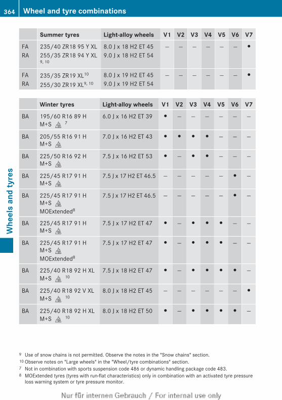
Summer tyres Light-alloy wheels V1 V2 V3 V4 V5 V6 V7
FARA
235/40 ZR18 95 Y XL255/35 ZR18 94 Y XL9, 10
8.0 J x 18 H2 ET 459.0 J x 18 H2 ET 54
— — — — — — #
FARA
235/35 ZR19 XL10
255/30 ZR19 XL9, 10
8.0 J x 19 H2 ET 459.0 J x 19 H2 ET 54
— — — — — — #
Winter tyres Light-alloy wheels V1 V2 V3 V4 V5 V6 V7
BA 195/60 R16 89 HM+Si7
6.0 J x 16 H2 ET 39 # — — — — — —
BA 205/55 R16 91 HM+Si
7.0 J x 16 H2 ET 43 # # # # — — —
BA 225/50 R16 92 HM+Si
7.5 J x 16 H2 ET 53 # — # # — — —
BA 225/45 R17 91 HM+Si
7.5 J x 17 H2 ET 46.5 — — — — — # —
BA 225/45 R17 91 HM+SiMOExtended8
7.5 J x 17 H2 ET 46.5 — — — — — # —
BA 225/45 R17 91 HM+Si
7.5 J x 17 H2 ET 47 # — # # # — —
BA 225/45 R17 91 HM+SiMOExtended8
7.5 J x 17 H2 ET 47 # — # # # — —
BA 225/40 R18 92 H XLM+Si10
7.5 J x 18 H2 ET 47 # — # # # # —
BA 225/40 R18 92 V XLM+Si10
8.0 J x 18 H2 ET 45 — — — — — — #
BA 225/40 R18 92 H XLM+Si10
8.0 J x 18 H2 ET 50 # — # # # # —
9 Use of snow chains is not permitted. Observe the notes in the "Snow chains" section.10 Observe notes on "Large wheels" in the "Wheel/tyre combinations" section.7 Not in combination with sports suspension code 486 or dynamic handling package code 483.8 MOExtended tyres (tyres with run-flat characteristics) only in combination with an activated tyre pressure
loss warning system or tyre pressure monitor.
364 Wheel and tyre combinationsW
heel
s an
d ty
res
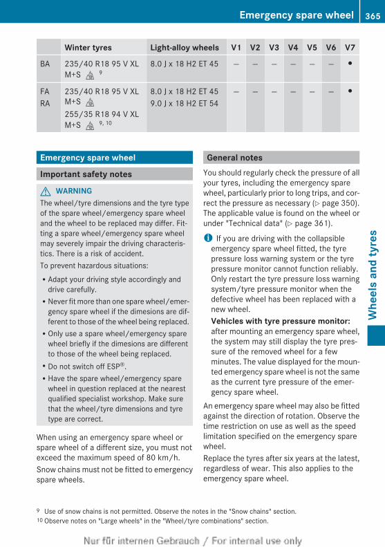
Winter tyres Light-alloy wheels V1 V2 V3 V4 V5 V6 V7
BA 235/40 R18 95 V XLM+Si9
8.0 J x 18 H2 ET 45 — — — — — — #
FARA
235/40 R18 95 V XLM+Si255/35 R18 94 V XLM+Si9, 10
8.0 J x 18 H2 ET 459.0 J x 18 H2 ET 54
— — — — — — #
Emergency spare wheel
Important safety notes
G WARNINGThe wheel/tyre dimensions and the tyre typeof the spare wheel/emergency spare wheeland the wheel to be replaced may differ. Fit-ting a spare wheel/emergency spare wheelmay severely impair the driving characteris-tics. There is a risk of accident.To prevent hazardous situations:RAdapt your driving style accordingly and
drive carefully.RNever fit more than one spare wheel/emer-
gency spare wheel if the dimesions are dif-ferent to those of the wheel being replaced.ROnly use a spare wheel/emergency spare
wheel briefly if the dimesions are differentto those of the wheel being replaced.RDo not switch off ESP®.RHave the spare wheel/emergency spare
wheel in question replaced at the nearestqualified specialist workshop. Make surethat the wheel/tyre dimensions and tyretype are correct.
When using an emergency spare wheel orspare wheel of a different size, you must notexceed the maximum speed of 80 km/h.Snow chains must not be fitted to emergencyspare wheels.
General notesYou should regularly check the pressure of allyour tyres, including the emergency sparewheel, particularly prior to long trips, and cor-rect the pressure as necessary (Y page 350).The applicable value is found on the wheel orunder "Technical data" (Y page 361).
i If you are driving with the collapsibleemergency spare wheel fitted, the tyrepressure loss warning system or the tyrepressure monitor cannot function reliably.Only restart the tyre pressure loss warningsystem/tyre pressure monitor when thedefective wheel has been replaced with anew wheel.Vehicles with tyre pressure monitor:after mounting an emergency spare wheel,the system may still display the tyre pres-sure of the removed wheel for a fewminutes. The value displayed for the moun-ted emergency spare wheel is not the sameas the current tyre pressure of the emer-gency spare wheel.
An emergency spare wheel may also be fittedagainst the direction of rotation. Observe thetime restriction on use as well as the speedlimitation specified on the emergency sparewheel.Replace the tyres after six years at the latest,regardless of wear. This also applies to theemergency spare wheel.
9 Use of snow chains is not permitted. Observe the notes in the "Snow chains" section.10 Observe notes on "Large wheels" in the "Wheel/tyre combinations" section.
Emergency spare wheel 365
Whe
els
and
tyre
s
Z
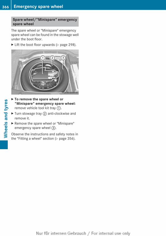
Spare wheel/"Minispare" emergencyspare wheel
The spare wheel or "Minispare" emergencyspare wheel can be found in the stowage wellunder the boot floor.X Lift the boot floor upwards (Y page 298).
X To remove the spare wheel or "Minispare" emergency spare wheel:remove vehicle tool kit tray :.
X Turn stowage tray ; anti-clockwise andremove it.
X Remove the spare wheel or "Minispare"emergency spare wheel =.
Observe the instructions and safety notes inthe "Fitting a wheel" section (Y page 356).
366 Emergency spare wheelW
heel
s an
d ty
res
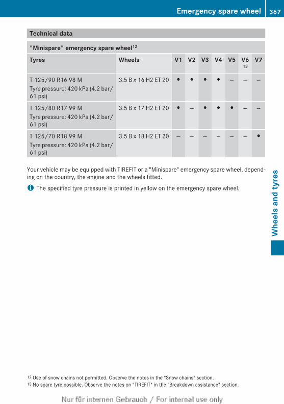
Technical data
"Minispare" emergency spare wheel12
Tyres Wheels V1 V2 V3 V4 V5 V613
V7
T 125/90 R16 98 MTyre pressure: 420 kPa (4.2 bar/61 psi)
3.5 B x 16 H2 ET 20 # # # # — — —
T 125/80 R17 99 MTyre pressure: 420 kPa (4.2 bar/61 psi)
3.5 B x 17 H2 ET 20 # — # # # — —
T 125/70 R18 99 MTyre pressure: 420 kPa (4.2 bar/61 psi)
3.5 B x 18 H2 ET 20 — — — — — — #
Your vehicle may be equipped with TIREFIT or a "Minispare" emergency spare wheel, depend-ing on the country, the engine and the wheels fitted.
i The specified tyre pressure is printed in yellow on the emergency spare wheel.
12 Use of snow chains not permitted. Observe the notes in the "Snow chains" section.13 No spare tyre possible. Observe the notes on "TIREFIT" in the "Breakdown assistance" section.
Emergency spare wheel 367
Whe
els
and
tyre
s
Z

368

Useful information ............................ 370Information on technical data ......... 370Vehicle electronics ........................... 370Identification plates ......................... 372Service products and capacities ..... 372Vehicle data ...................................... 380Trailer tow hitch ................................ 381
369
Tech
nica
l dat
a
Useful information
i This Owner's Manual describes all mod-els, series and optional equipment for yourvehicle that were available at the time ofgoing to press. National variations are pos-sible. Note that your vehicle may not beequipped with all of the functions descri-bed. This is also the case for systems andfunctions relevant to safety.
i Read the information on qualified special-ist workshops: (Y page 28).
Information on technical data
General notesYou can find current technical data on theInternet at:http://www.mercedes-benz.com
i The technical data was determined inaccordance with EU Directives. All dataapplies to the vehicle's standard equip-ment. The data may therefore differ forvehicles with optional equipment. You canobtain further information from aMercedes-Benz Service Centre.
Vehicle electronics
Tampering with the engine electron-ics
! Only have work carried out on the engineelectronics and its associated parts, suchas control units, sensors and connectorleads, at a qualified specialist workshop.Vehicle components may otherwise wearmore quickly and the vehicle's operatingpermit may be invalidated.
Retrofitting two-way radios andmobile phones (RF transmitters)
G WARNINGIf RF transmitters are tampered with or notproperly retrofitted, the electromagnetic radi-ation they emit can interfere with the vehicleelectronics. This may jeopardise the opera-tional safety of the vehicle. There is a risk ofan accident.You should have all work on electrical andelectronic components carried out at a quali-fied specialist workshop.
G WARNINGIf you use the RF transmitter in the vehicle inan improper way, its electromagnetic radia-tion can disrupt vehicle electronics, e.g. if:Rthe RF transmitter is not connected to an
exterior aerialRthe exterior aerial is fitted incorrectly or is
not a low-reflection aerialThis can jeopardise the operating safety of thevehicle. There is a risk of an accident.Have the low-reflection exterior aerial fitted ata qualified specialist workshop. When oper-ating in the vehicle, always connect the RFtransmitter to the low-reflection exterior aer-ial.
! The operating permit may be invalidatedif the instructions for installation and use ofRF transmitters are not observed.In particular, the following conditions mustbe complied with:Ronly approved wavebands may be used.Robserve the maximum permissible out-
put in these wavebands.Ronly approved aerial positions may be
used.Excessive levels of electromagnetic radiationmay cause damage to your health and to thehealth of others. The use of an exterior aerialtakes into consideration the scientific discus-
370 Vehicle electronicsTe
chni
cal d
ata
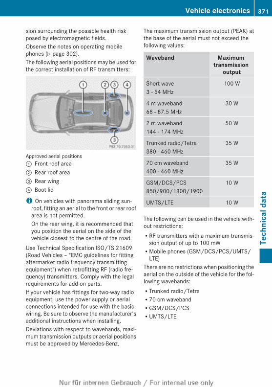
sion surrounding the possible health riskposed by electromagnetic fields.Observe the notes on operating mobilephones (Y page 302).The following aerial positions may be used forthe correct installation of RF transmitters:
Approved aerial positions: Front roof area; Rear roof area= Rear wing? Boot lid
i On vehicles with panorama sliding sun-roof, fitting an aerial to the front or rear roofarea is not permitted.On the rear wing, it is recommended thatyou position the aerial on the side of thevehicle closest to the centre of the road.
Use Technical Specification ISO/TS 21609(Road Vehicles – "EMC guidelines for fittingaftermarket radio frequency transmittingequipment") when retrofitting RF (radio fre-quency) transmitters. Comply with the legalrequirements for add-on parts.If your vehicle has fittings for two-way radioequipment, use the power supply or aerialconnections intended for use with the basicwiring. Be sure to observe the manufacturer'sadditional instructions when installing.Deviations with respect to wavebands, maxi-mum transmission outputs or aerial positionsmust be approved by Mercedes-Benz.
The maximum transmission output (PEAK) atthe base of the aerial must not exceed thefollowing values:
Waveband Maximum transmission
output
Short wave3 - 54 MHz
100 W
4 m waveband68 - 87.5 MHz
30 W
2 m waveband144 - 174 MHz
50 W
Trunked radio/Tetra380 - 460 MHz
35 W
70 cm waveband400 - 460 MHz
35 W
GSM/DCS/PCS850/900/1800/1900
10 W
UMTS/LTE 10 W
The following can be used in the vehicle with-out restrictions:RRF transmitters with a maximum transmis-
sion output of up to 100 mWRMobile phones (GSM/DCS/PCS/UMTS/
LTE)There are no restrictions when positioning theaerial on the outside of the vehicle for the fol-lowing wavebands:RTrunked radio/TetraR70 cm wavebandRGSM/DCS/PCSRUMTS/LTE
Vehicle electronics 371
Tech
nica
l dat
a
Z
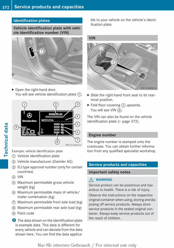
Identification plates
Vehicle identification plate with vehi-cle identification number (VIN)
X Open the right-hand door.You will see vehicle identification plate :.
Example: vehicle identification plate: Vehicle identification plate; Vehicle manufacturer (Daimler AG)= EU type approval number (only for certain
countries)? VINA Maximum permissible gross vehicle
weight (kg)B Maximum permissible mass of vehicle/
trailer combination (kg)C Maximum permissible front axle load (kg)D Maximum permissible rear axle load (kg)E Paint code
i The data shown on the identification plateis example data. This data is different forevery vehicle and can deviate from the datashown here. You can find the data applica-
ble to your vehicle on the vehicle's identi-fication plate.
VIN
X Slide the right-hand front seat to its rear-most position.
X Fold floor covering : upwards.You will see VIN ;.
The VIN can also be found on the vehicleidentification plate (Y page 372).
Engine numberThe engine number is stamped onto thecrankcase. You can obtain further informa-tion from any qualified specialist workshop.
Service products and capacities
Important safety notes
G WARNINGService product can be poisonous and haz-ardous to health. There is a risk of injury.Observe the instructions on the respectiveoriginal container when using, storing and dis-posing off service products. Always storeservice products in the sealed original con-tainer. Always keep service products out ofthe reach of children.
372 Service products and capacitiesTe
chni
cal d
ata
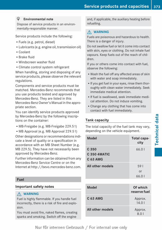
H Environmental noteDispose of service products in an environ-mentally-responsible manner.
Service products include the following:RFuels (e.g. petrol, diesel)RLubricants (e.g. engine oil, transmission oil)RCoolantRBrake fluidRWindscreen washer fluidRClimate control system refrigerantWhen handling, storing and disposing of anyservice products, please observe the relevantregulations.Components and service products must bematched. Mercedes-Benz recommends thatyou use products tested and approved byMercedes-Benz. They are listed in thisMercedes-Benz Owner's Manual in the appro-priate section.You can identify service products approvedby Mercedes-Benz by the following inscrip-tions on the container:RMB-Freigabe (e.g. MB-Freigabe 229.51)RMB Approval (e.g. MB Approval 229.51)Other designations or recommendations indi-cate a level of quality or a specification inaccordance with an MB Sheet Number (e.g.MB 229.5). They have not necessarily beenapproved by Mercedes-Benz.Further information can be obtained from anyMercedes-Benz Service Centre or on theInternet at http://bevo.mercedes-benz.com.
Fuel
Important safety notes
G WARNINGFuel is highly flammable. If you handle fuelincorrectly, there is a risk of fire and explo-sion.You must avoid fire, naked flames, creatingsparks and smoking. Switch off the engine
and, if applicable, the auxiliary heating beforerefuelling.
G WARNINGFuels are poisonous and hazardous to health.There is a danger of injury.Do not swallow fuel or let it come into contactwith skin, eyes or clothing. Do not inhale fuelvapours. Keep fuels out of the reach of chil-dren.If you or others come into contact with fuel,observe the following:RWash the fuel off any affected areas of skin
with water and soap immediately.RIf you get fuel in your eyes, rinse them thor-
oughly with clean water immediately. Seekimmediate medical attention.RIf fuel is swallowed, seek immediate medi-
cal attention. Do not induce vomiting.RChange any clothing that has come into
contact with fuel immediately.
Tank capacityThe total capacity of the fuel tank may vary,depending on the vehicle equipment.
Model Total capa-city
C 350C 350 4MATICC 63 AMG
66.0 l
All other models 59 lor
66.0 l
Model Of whichreserve fuel
C 63 AMG Approx.14.0 l
All other models Approx.8.0 l
Service products and capacities 373
Tech
nica
l dat
a
Z
Petrol (EN 228, E DIN 51626-1)
Fuel grade! Do not use diesel to refuel vehicles with a
petrol engine. Do not switch on the ignitionif you accidentally refuel with the wrongfuel. Otherwise, fuel can enter the fuel sys-tem. Even small amounts of the wrong fuelcould result in damage to the fuel systemand the engine. Notify a qualified specialistworkshop and have the fuel tank and fuellines drained completely.
! Only refuel using premium-grade unlea-ded petrol with at least 95 ROZ/85 MOZ,that conforms to European standardEN 228 or E DIN 51626–1 or an equivalentspecification.Fuel of this specification can contain up to10 % ethanol.Fuel that does not conform to EN 228 orE DIN 51626–1 can lead to increased wearand damage the engine and exhaust sys-tem.
! Only use the fuel recommended. Operat-ing the vehicle with other fuels can lead toengine failure.
! Do not use the following:RE85 (petrol with 85% ethanol)RE100 (100% ethanol)RM15 (petrol with 15% methanol)RM30 (petrol with 30% methanol)RM85 (petrol with 85% methanol)RM100 (100% methanol)RPetrol with additives containing metalRDieselDo not mix such fuels with the fuel recom-mended for your vehicle. Do not use addi-tives. This can otherwise lead to enginedamage. This does not include cleaningadditives for the removal and prevention ofresidue build-up. Petrol must only be mixedwith additives recommended by Mercedes-Benz; see "Additives". You can obtain fur-
ther information from any Mercedes-BenzService Centre.
Usually you will find information about thefuel grade on the pump. If you cannot find thelabel on the petrol pump, ask the filling sta-tion staff.
i E10 fuel contains up to 10% bioethanol.Your vehicle is suitable for use with E10fuel. You can refuel your vehicle using E10fuel.
i C 180 BlueEFFICIENCY: as a temporarymeasure, if the recommended fuel is notavailable, you may also use unleaded petrolwith an octane rating of 93 RON/83 MON.All other models: as a temporary meas-ure, if the recommended fuel is not availa-ble, you may also use unleaded petrol withan octane rating of 91 RON/82 MON. Thismay reduce engine performance andincrease fuel consumption. Avoid driving atfull throttle.
i In some countries, the available petrolmay not be sufficiently low in sulphur. Thisfuel can temporarily produce unpleasantodours, especially on short journeys. Assoon as sulphur-free fuel (sulphur content< 10 ppm) is used for refuelling, the odoursare reduced.
Information on refuelling (Y page 165).
AMG vehicles! Only refuel using super unleaded petrol
with at least 98 RON/88 MON that con-forms to European standard EN 228 or anequivalent specification.You can otherwise impair engine output ordamage the engine.
! Premium-grade unleaded petrol with anoctane rating of 95 RON/85 MON may beused as a temporary measure if the recom-mended fuel is not available. This mayreduce engine performance and increasefuel consumption. As much as possible,avoid driving at full throttle.
374 Service products and capacitiesTe
chni
cal d
ata
! Regular unleaded petrol with an octanerating of 91 RON/82.5 MON may also beused as a temporary measure if the recom-mended fuel is not available.Doing so results in noticeably higher fuelconsumption, and the engine power outputis noticeably reduced. Avoid driving at fullthrottle.If only regular unleaded petrol with anoctane rating of 91 RON/82.5 MON orlower is available, you must have the vehi-cle adapted to this fuel at a qualified spe-cialist workshop.
i E10 fuel contains up to 10% bioethanol.Your vehicle is suitable for use with E10fuel. You can refuel your vehicle using E10fuel.
C 350! Only refuel using premium-grade sulphur-
free unleaded petrol with at least 95 RON/85 MON that conforms to European stand-ard EN 228 or an equivalent specification.You could otherwise impair engine outputor damage the emission control system.
i In some countries, the available petrolmay not be sufficiently low in sulphur. Thisfuel can temporarily produce unpleasantodours, especially on short journeys. Assoon as sulphur-free fuel (sulphur content< 10 ppm) is used for refuelling, the odoursare reduced.
Additives! Operating the engine with fuel additives
added later can lead to engine failure. Donot mix fuel additives with fuel. This doesnot include additives for the removal andprevention of residue build-up. Petrol mustonly be mixed with additives recommendedby Mercedes-Benz. Observe the instruc-tions for use in the product description.More information about recommendedadditives can be obtained from anyMercedes-Benz Service Centre.
Mercedes-Benz recommends that you usefuel brands that have additives.The quality of the fuel available in some coun-tries may not be sufficient. Residue couldbuild up as a result. In such cases, and inconsultation with a Mercedes-Benz ServiceCentre, the petrol may be mixed with thecleaning additive recommended byMercedes-Benz (part no. A000989254512).You must observe the notes and mixing ratiosspecified on the container.
Diesel (EN 590)
Fuel gradeG WARNINGIf you mix diesel fuel with petrol, the flashpoint of this fuel mixture is lower than that ofpure diesel fuel. When the engine is running,components in the exhaust system may over-heat unnoticed. There is a risk of fire.Never refuel with petrol. Never add petrol todiesel fuel.
! When refuelling, only use diesel fuel thatconforms to the European standard EN 590or is of equivalent quality. Fuel that doesnot conform to EN 590 can lead toincreased wear as well as damage to theengine and exhaust system.
! Do not use the following:Rmarine dieselRheating oilRbio-dieselRvegetable oilRpetrolRparaffinRkeroseneDo not mix such fuels with diesel fuel anddo not use any special additives. This canotherwise lead to engine damage. Thisdoes not include flow improver additives.For further information, see "Flow improv-ers".
Service products and capacities 375
Tech
nica
l dat
a
Z
! Vehicles with a diesel particle filter: incountries outside the EU, only refuel withlow-sulphur Euro diesel with a sulphur con-tent under 50 ppm; otherwise the emissioncontrol system could be damaged.
! Vehicles without a diesel particle fil-ter: in countries where only diesel fuel witha high sulphur content is available, you willneed to carry out your vehicle's oil changeat shorter intervals. More informationabout the interval for oil change can beobtained from any qualified specialistworkshop.
Usually you will find information about thefuel grade on the pump. If you cannot find thelabel on the petrol pump, ask the filling sta-tion staff.Information on refuelling (Y page 165).
Low outside temperaturesIn winter months, diesel fuel with an improvedcold flow quality is available. In Europe, theEN 590 standard defines various climate-dependent temperature categories. Malfunc-tions can be avoided by refuelling with dieselfuel that corresponds to the climatic specifi-cations outlined in EN 590. At unusually lowoutside temperatures, it is possible that theflow characteristics of the diesel fuel could beinsufficient. Accordingly, diesel fuel fromwarmer areas may not be suitable for opera-tion in colder climatic conditions.
i Further information on country-specificfuel properties can be obtained from oilcompanies, e.g. at filling stations.
Fuel consumption information
H Environmental noteCO2 (carbon dioxide) is the gas which scien-tists believe to be principally responsible forglobal warming (the greenhouse effect). Yourvehicle's CO2 emissions are directly related tofuel consumption and therefore depend on:
Refficient use of the fuel by the engineRdriving styleRother non-technical factors, such as envi-
ronmental influences, road conditions ortraffic flow
You can minimise your vehicle's CO2 emis-sions by driving carefully and having it serv-iced regularly.
The vehicle will use more fuel than usual inthe following situations:Rat very low outside temperaturesRin urban trafficRon short journeysRin mountainous terrainRwhen towing a trailer
i Only for certain countries: you can findthe current consumption and emission val-ues of your vehicle in the COC documents(EU CERTIFICATE OF CONFORMITY). Thesedocuments are delivered with your vehicle.The consumption figures were in each casebased on the currently applicable version:Rfor vehicles that comply with standards
up to and including the EURO 4 standard,in accordance with EU Directive80/1268/EECRfor vehicles that comply with or exceed
the EURO 5 standard, in accordance withRegulation (EC) No. 715/2007
Deviations from these values may occurunder normal operating conditions.
Engine oil
General notesWhen handling engine oil, observe the impor-tant safety notes on service products(Y page 372).The quality of the engine oil is decisive for thefunction and service life of an engine. Afterextensive tests, Mercedes-Benz approves
376 Service products and capacitiesTe
chni
cal d
ata
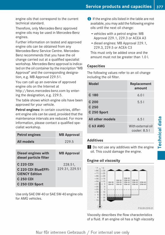
engine oils that correspond to the currenttechnical standard.Therefore, only Mercedes-Benz approvedengine oils may be used in Mercedes-Benzengines.Further information on tested and approvedengine oils can be obtained from anyMercedes-Benz Service Centre. Mercedes-Benz recommends that you have the oilchange carried out at a qualified specialistworkshop. Mercedes-Benz approval is indica-ted on the oil container by the inscription "MBApproval" and the corresponding designa-tion, e.g. MB Approval 229.51.You can call up an overview of approvedengine oils on the Internet athttp://bevo.mercedes-benz.com by enter-ing the designation, e.g. 229.5.The table shows which engine oils have beenapproved for your vehicle.Petrol engines: in certain countries, differ-ent engine oils can be used, provided that themaintenance intervals are reduced. For moreinformation, please contact a qualified spe-cialist workshop.
Petrol engines MB Approval
All models 229.5
Diesel engines withdiesel particle filter
MB Approval
C 220 CDIC 220 CDI BlueEFFI-CIENCY EditionC 250 CDIC 250 CDI Sport
228.51,229.31, 229.51
Use only SAE 0W-40 or SAE 5W-40 engine oilsfor AMG vehicles.
i If the engine oils listed in the table are notavailable, you may add the following engineoils until the next oil change:Rvehicles with a petrol engine: MB
Approval 229.1, 229.3 or ACEA A3Rdiesel engines: MB Approval 229.1,
229.3, 229.5 or ACEA C3This must only be added once and theamount must not be greater than 1.0 l.
CapacitiesThe following values refer to an oil changeincluding the oil filter.
Model Replacementamount
C 180 6.0 l
C 200C 250C 250 Sport
5.5 l
All other models 6.5 l
C 63 AMG With external oilcooler: 8.5 l
Additives! Do not use any additives with the engine
oil. This could damage the engine.
Engine oil viscosity
Viscosity describes the flow characteristicsof a fluid. If an engine oil has a high viscosity
Service products and capacities 377
Tech
nica
l dat
a
Z
rating, it flows slowly; the lower the viscosity,the faster it flows.Engine oil selection is based on the respectiveoutside temperatures and in accordance withthe SAE classification (viscosity). The tableshows you which SAE classifications are to beused. The low-temperature properties ofengine oils can be significantly impaired dur-ing operation due to, for example, ageing orsoot and fuel accretion. It is thereforestrongly recommended to observe regular oilchanges using an approved engine oil with theappropriate SAE classification.
Brake fluid
G WARNINGThe brake fluid continuously absorbs mois-ture from the air. This results in the boilingpoint of the brake fluid lowering. If the boilingpoint of the brake fluid is too low, vapourpockets may form when the brakes are sub-jected to a heavy load. This would impair brak-ing efficiency. There is a risk of an accident.Have the brake fluid renewed at the prescri-bed intervals.
When handling brake fluid, observe theimportant safety notes on service products(Y page 372).The brake fluid change intervals can be foundin the Service Booklet.Only use brake fluid approved by Mercedes-Benz according to MB Approval 331.0.Information about approved brake fluid canbe obtained at any qualified specialist work-shop or on the Internet at:http://bevo.mercedes-benz.com.
i Have the brake fluid regularly replaced ata qualified specialist workshop and thereplacement confirmed in the ServiceBooklet.
Coolant
Important safety notes
G WARNINGIf antifreeze comes into contact with hot com-ponents in the engine compartment, it mayignite. There is a risk of fire and injury.Let the engine cool down before you top upthe antifreeze. Make sure that antifreeze isnot spilled next to the filler neck. Thoroughlyclean the antifreeze from components beforestarting the engine.
! Only add coolant that has been premixedwith the desired antifreeze protection. Youcould otherwise damage the engine.Further information on coolants can befound in the Mercedes-Benz Specificationsfor Service Products, MB Specifications forService Products 310.1, e.g. on the Inter-net at http://bevo.mercedes-benz.com.Or contact a qualified specialist workshop.
! Always use a suitable coolant mixture,even in countries where high temperaturesprevail.Otherwise, the engine cooling system is notsufficiently protected from corrosion andoverheating.
i Have the coolant regularly replaced at aqualified specialist workshop and thereplacement confirmed in the ServiceBooklet.
Comply with the important safety precautionsfor service products when handling coolant(Y page 372).The coolant is a mixture of water and anti-freeze/corrosion inhibitor. It is responsiblefor the following:Ranti-corrosion protectionRantifreeze protectionRraising the boiling pointIf antifreeze/corrosion inhibitor is present inthe correct concentration, the boiling point of
378 Service products and capacitiesTe
chni
cal d
ata
the coolant during operation will be approx-imately 130 †.The antifreeze/corrosion inhibitor concentra-tion in the engine cooling system should:Rbe at least 50%. This will protect the engine
cooling system against freezing down toapproximately -37 †.Rnot exceed 55% (antifreeze protection
down to -45 †). Heat will otherwise not bedissipated as effectively.
If the vehicle has lost coolant, top it up withequal amounts of water and antifreeze/cor-rosion inhibitor.Mercedes-Benz recommends an antifreeze/corrosion inhibitor concentrate in accord-ance with MB Specifications for Service Prod-ucts 310.1.
i When the vehicle is first delivered, it is fil-led with a coolant mixture that ensuresadequate antifreeze and corrosion protec-tion.
i The coolant is checked at every mainte-nance interval at a qualified specialistworkshop.
Windscreen washer system and head-lamp cleaning system
Important safety notes
G WARNINGWindscreen washer concentrate is highlyflammable. If it comes into contact with hotengine components or the exhaust system itcould ignite. There is a risk of fire and injury.Make sure that no windscreen washer con-centrate is spilled next to the filler neck.
! Only use washer fluid that is suitable forplastic lamp lenses, e.g. MB SummerFit orMB WinterFit. Unsuitable washer fluidcould damage the plastic lenses of theheadlamps.
! Do not use distilled or de-ionised water inthe washer fluid reservoir. Otherwise, thelevel sensor may be damaged.
! Only the washer fluids SummerFit andWinterFit can be mixed. Otherwise, thespraying nozzles could become blocked.
When handling washer fluid, observe theimportant safety notes on service products(Y page 372).At temperatures above freezing:X Fill the washer fluid reservoir with a mixture
of water and washer fluid, e.g. MB Sum-merFit.
X Mix 1 part MB SummerFit to 100 partswater.
At temperatures below freezing:X Fill the washer fluid reservoir with a mixture
of water and washer fluid, e.g. MB Winter-Fit.
Adapt the mixing ratio to the outside temper-ature.RDown to Ò10 †: mix 1 part MB WinterFit to
2 parts water.RDown to Ò20 †: mix 1 part MB WinterFit to
1 part water.RDown to Ò29 †: mix 2 parts MB WinterFit
to 1 part water.
i Add washer fluid concentrate, e.g. MBSummerFit or MB WinterFit, to the washerfluid all year round.
Service products and capacities 379
Tech
nica
l dat
a
Z
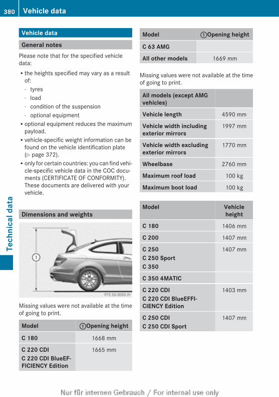
Vehicle data
General notesPlease note that for the specified vehicledata:Rthe heights specified may vary as a result
of:- tyres- load- condition of the suspension- optional equipmentRoptional equipment reduces the maximum
payload.Rvehicle-specific weight information can be
found on the vehicle identification plate(Y page 372).Ronly for certain countries: you can find vehi-
cle-specific vehicle data in the COC docu-ments (CERTIFICATE OF CONFORMITY).These documents are delivered with yourvehicle.
Dimensions and weights
Missing values were not available at the timeof going to print.
Model :Opening height
C 180 1668 mm
C 220 CDIC 220 CDI BlueEF-FICIENCY Edition
1665 mm
Model :Opening height
C 63 AMG
All other models 1669 mm
Missing values were not available at the timeof going to print.
All models (except AMGvehicles)
Vehicle length 4590 mm
Vehicle width including exterior mirrors
1997 mm
Vehicle width excluding exterior mirrors
1770 mm
Wheelbase 2760 mm
Maximum roof load 100 kg
Maximum boot load 100 kg
Model Vehicleheight
C 180 1406 mm
C 200 1407 mm
C 250C 250 SportC 350
1407 mm
C 350 4MATIC
C 220 CDIC 220 CDI BlueEFFI-CIENCY Edition
1403 mm
C 250 CDIC 250 CDI Sport
1407 mm
380 Vehicle dataTe
chni
cal d
ata
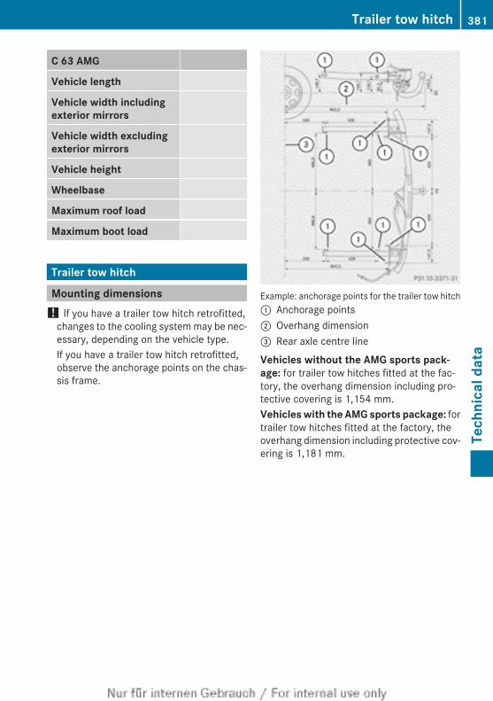
C 63 AMG
Vehicle length
Vehicle width including exterior mirrors
Vehicle width excluding exterior mirrors
Vehicle height
Wheelbase
Maximum roof load
Maximum boot load
Trailer tow hitch
Mounting dimensions! If you have a trailer tow hitch retrofitted,
changes to the cooling system may be nec-essary, depending on the vehicle type.If you have a trailer tow hitch retrofitted,observe the anchorage points on the chas-sis frame.
Example: anchorage points for the trailer tow hitch: Anchorage points; Overhang dimension= Rear axle centre line
Vehicles without the AMG sports pack-age: for trailer tow hitches fitted at the fac-tory, the overhang dimension including pro-tective covering is 1,154 mm.Vehicles with the AMG sports package: fortrailer tow hitches fitted at the factory, theoverhang dimension including protective cov-ering is 1,181 mm.
Trailer tow hitch 381
Tech
nica
l dat
a
Z
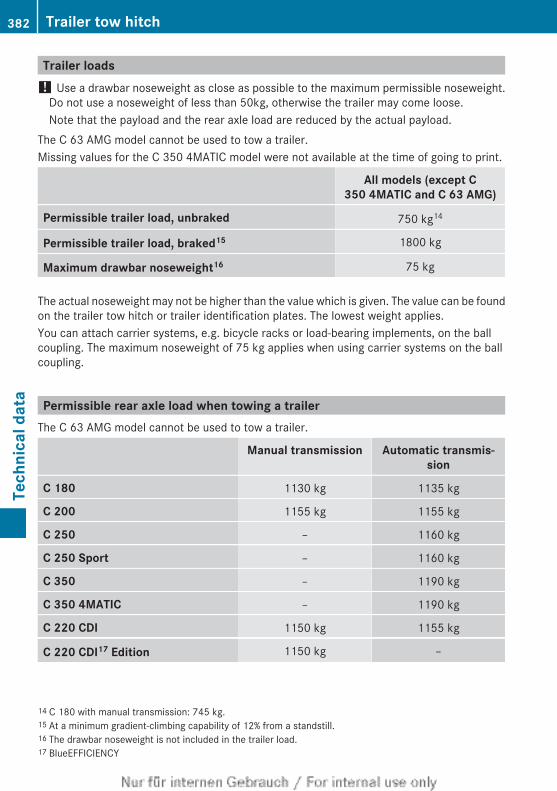
Trailer loads! Use a drawbar noseweight as close as possible to the maximum permissible noseweight.
Do not use a noseweight of less than 50kg, otherwise the trailer may come loose.Note that the payload and the rear axle load are reduced by the actual payload.
The C 63 AMG model cannot be used to tow a trailer.Missing values for the C 350 4MATIC model were not available at the time of going to print.
All models (except C 350 4MATIC and C 63 AMG)
Permissible trailer load, unbraked 750 kg14
Permissible trailer load, braked15 1800 kg
Maximum drawbar noseweight16 75 kg
The actual noseweight may not be higher than the value which is given. The value can be foundon the trailer tow hitch or trailer identification plates. The lowest weight applies.You can attach carrier systems, e.g. bicycle racks or load-bearing implements, on the ballcoupling. The maximum noseweight of 75 kg applies when using carrier systems on the ballcoupling.
Permissible rear axle load when towing a trailerThe C 63 AMG model cannot be used to tow a trailer.
Manual transmission Automatic transmis-sion
C 180 1130 kg 1135 kg
C 200 1155 kg 1155 kg
C 250 – 1160 kg
C 250 Sport – 1160 kg
C 350 – 1190 kg
C 350 4MATIC – 1190 kg
C 220 CDI 1150 kg 1155 kg
C 220 CDI17 Edition 1150 kg –
14 C 180 with manual transmission: 745 kg.15 At a minimum gradient-climbing capability of 12% from a standstill.16 The drawbar noseweight is not included in the trailer load.17 BlueEFFICIENCY
382 Trailer tow hitchTe
chni
cal d
ata
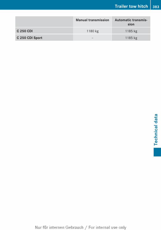
Manual transmission Automatic transmis-sion
C 250 CDI 1180 kg 1185 kg
C 250 CDI Sport – 1185 kg
Trailer tow hitch 383
Tech
nica
l dat
a
Z

384
Publication detailsInternet
Further information about Mercedes-Benzvehicles and about Daimler AG can be foundon the following websites:http://www.mercedes-benz.comhttp://www.daimler.com
Editorial office
You are welcome to forward any queries orsuggestions you may have regarding thisOwner's Manual to the technical documenta-tion team at the following address:Daimler AG, HPC: CAC, Customer Service,70546 Stuttgart, Germany©Daimler AG: not to be reprinted, translatedor otherwise reproduced, in whole or in part,without written permission from Daimler AG.
Vehicle manufacturer
Daimler AGMercedesstraße 13770327 StuttgartGermany
As at 31.10.2012

Order no. 65150797 02 Part no. 2045843783Z102 Edition ÄJ 2013-1a
É2045843783Z102{ËÍ2045843783Z102
Nur für internen Gebrauch / For internal use only