Embed Size (px)
Citation preview
NASA/CR--
FAX: (216) 962-3192
J.V. POPLAWSKI & ASSOCIATES
_,_no,,Iting Mechanical Engineers
207542 May 19, 1997
Mr. Wally Rakowski
Program Manager
Ohio Aerospace Institute22800 Cedar Point Row
Cleveland, OH 44142
/ 2/_ 3 2- c
Subject: Profiled Roller Stress/Fatigue Life AnalysisMethodology and Establishment of an Appropriate
Stress/Life Exponent - Results Summary
Reference: OAI Project NAG3-1938-JPA
This letter report contains the pertinent results ofwork conducted under the referenced OAI project.
OBJECTIVE OF WORK
The objective of this work was to determine the threedimensional volumetric stress field, surface pressure
distribution and actual contact area between a 0.50" square
roller with different crown profiles and a flat raceway
surface using Finite Element Analysis. The 3-dimensionalstress field data was used in conjunction with several
bearing fatigue life theories to extract appropriate values
for stress-life exponents. Also, results of the FEA runs wereused to evaluate the laminated roller model presently used
for stress and life prediction.
APPROACH
Our approach was to develop a 3-Dimensional finite
element model geometry of a 0.5" x 0.5" profiled roller
contacting a flat raceway and utilize the model to determinethe actual surface pressure, contact area and volumetric
stress fields developed within the raceway material for four
profile shapes and at three Hertz stress levels. The four
standard profiles studied were as follows:
* Flat or Straight Roller* Roller With Flat Length + End Taper
* Fully Crowned Roller
* Aerospace Crown (Flat Length + Crown Radius)
CONMEC Bldg • 1480 Valley Center Parkway • Bethlehem, Pennsylvania 18017 • 610-758-7508 Fax 610-758-7501
Bearings • Mechanical Systems • Metals Rolling Analysis • Finite Element Analysis
https://ntrs.nasa.gov/search.jsp?R=19980021235 2018-07-07T05:39:15+00:00Z

Each roller profile model was run at nominal Hertz
contact stress levels of 350,000 psi, 275,000 psi and 200,000
psi maximum stress. Subsequently, calculated Von Mises, In-
Plane Shear, Orthogonal Shear, element volumes and depthswere extracted from the FEA runs to form a stress data base
for determination of stress-life exponents according to the
various life theories of current interest. The FEA model
computed maximum interface contact stress was also noted for
comparison with those derived using the "laminated" roller
model as applied to the four crown profiles being studied.
RESULTS
The results of these studies are presented in the
attached tables. Tables I to III summarize pertinent stress,
depth and model data for each of the values of nominal Hertz
stress studied. Hertz line contact stress theory was used to
calculate an applied load that corresponds to the specific
nominal value of Hertz stress. For example, a 3149# load
would give 350,000 psi Max. Hertz stress on the 0.5" roller.Table I shows that the same load would result in different
Hertz stress levels depending on the roller profile. The FEA
model Center Surface Hertz stress listed in Table I shows
that the Max. Hertz stress varies from 411,000 psi for the
fully crowned roller to a minimum of 361,000 psi for the
roller with end-taper. This trend also appears in Tables II
and III.
STRESS-LIFE EXPONENT
The basic data in Tables I to III was combined with the
corresponding 3-dimensional volumetric stress field data
bases to estimate stress/life exponents that are derived from
the three fatigue life models of interest. Tables IV-VI show
the corresponding "Relative Life" and back calculated
stress/life exponents for the Zaretsky-Weibull, Lundberg-
Palmgren and Ioannides-Harris life theories. The method used
is discussed in a similar study of a ball contact by
Zaretsky, Poplawski and Peters (1996). These calculations
were performed by normalizing the study to the 350,000 psimaximum Hertz stress values.
Table IV shows back calculated Stress/Life exponents
if one were to choose the Von-Mises stress as the stress of
comparison. The Zaretsky-Weibull (ZW) model estimates stress
-life exponents in the range of 8.6 to 14.3 depending on the
profile and stress level selected. These values are very
reasonable. The corresponding values of 21.7 to 31.2 for the
Flat roller imply a more sensitive behavior. This is due to
the edge stress developed in this roller. The classical
Lundberg-Palmgren (LP) theory estimates exponents in the
range of 8.7 to 14.7 for the Aerospace, Full Crown and End
Taper profile. These compare well with the WZ theory. For the
flat roller the exponents increase to 24.9 to 38.6. Once
gain, this sensitivity increase is due to the edge stressconcentration.
- 2 -

The Ioannedis-Harris (IH) theory requires one to select
a value for the Endurance Limiting Stress for infinite life.
IH publications regarding their theory have shown differentvalues for this stress for the same material. Therefore, we
exercised this theory for several limiting stresses that
cover the range of values seen in their papers. For high
values of limiting stress, large exponents in the range of 24to 52 are derived. These are about 3 times those derived from
the WZ and LP theories. For low values of limiting stress,
the exponents begin to approach those of LP and WZ. An
independent experimental test would have to be designed todetermine the physical property of Limiting Stress as opposed
to using a value that allows theory- bearing test data match.
Table V presents relative life and extracted exponents
using the Maximum In-Plane Shear stress typically referred to
as Tau 45. The stress-life exponents (excluding the flat
roller) are reasonable using the ZW and LP theories. These
values increase for the flat roller as previously discussed.
Once again, the IH theory gives unreasonable high values that
decrease as the selected limiting stress is reduced.
Table VI repeats the study using the Orthogonal Shear
stress. The resulting exponent magnitudes and trends are
similar to the previous results.
LAMXN&TED ROLLER Model
A "stand alone" computer program called CROWN was
developed using the approach of Radzimovsky (1953) to
determine the non-uniform stress pattern across a profiled
misaligned roller. The program analyzes a single rollercontact of a crowned roller under Load and Misalignment by
"slicing" the roller into thin disks or lamina. An iterative
solution is required to determine the non-uniform load
pattern developed across the roller interface. Upon reachingequilibrium, the lamina contact stress is calculated using
Hertz 2-D line contact stress theory. That stress is assumed
to be uniform across the width of 1 lamina. As previously
mentioned, the "lamina" approach has been used from the early
programs of Jones (1960) to more recent programs such as
SHABERTH (1981). This method has provided a design tool for
analyzing crowned rollers for many years.
The laminated roller model does not predict stress
concentration at the edge of the roller if it contacts the
race. Therefore, designers attempt to add enough crown to
avoid edge contact or to keep the edge stress estimated with
the model to a very low value. Also, since this model isnumerical in nature, the number of lamina placed across the
roller should govern the accuracy of the solution. More
accuracy requires increasing the number of lamina. However,this also adds computational time. Many computer codes set
the number of slices at 20. Some analysts have complained
- 3 -

that more slices are needed to better represent the roller.
Arguments have developed with regard to this issue. Also,the laminated roller models inherent in these codes are used
to model fully crowned rollers. The calculation of contact
stress in a fully crowned roller requires the use of 3-D
Hertzian elliptical contact stress theory. Stresses
calculated with 2-D theory at the interface of a slice in a
fully crowned roller will underestimate the stress. This may
have a significant effect on the life estimate since stress
and life are inversely proportional to a 9 to 12 power.
CROWN Program Results
The stress distribution for each of the 4 crown profiles
on the 0.5" square roller were analyzed at nominal contact
stress levels of 275 ksi, 300 ksi and 350 ksi using the CROWN
program. This was done while the number of "lamina" werevaried from i0 to 80. The results showed that the calculated
stress pattern across the roller did not vary as a function
of the number of lamina used. However, The contact life would
be different since lamina width does change.
The LI0 Fatigue Life of the contact was determined using
the SHABERTH and our BRG programs. A "dummy" radial bearing
having 4 rollers was analyzed by applying a radial load to
the bearing equivalent to the roller load used in the
previous analysis. In such a bearing, a roller resides at 0,
90, 180 and 270 degrees location. Thus, under radial load,
only the roller at 180 degrees or Bottom Dead Center is
loaded to a value equal to the applied load. An inner ring
rotational speed was assumed at i00.
Table VII compares LI0 life estimates for each roller
model with different number of lamina. These results indicate
that a lamina width of 10% or less of the roller length was
required for accurate life estimation.
LI0 Fatigue Life estimates via a laminated roller models
in our BRG program were compared to those of SHABERTH. Table
VIII shows that the stress level and LI0 life estimates that
were predicted using each code agreed very well.
Finally, the adequacy of the laminated roller model to
represent a "fully crowned" roller was investigated by
comparing the estimated Maximum Hertz stress from the CROWN
program to Hertz 3-D elliptical contact theoretical
calculations. Table IX compares the Hertz stresses from a 20
and 40 lamina model to theoretical predictions. Notice that
at the 200ksi and 275ksi nominal levels, the laminated roller
model is underestimating the stress in the fully crowned
roller by 2.5% to 3.5%. This corresponds to underestimating
life by 24 to 37% using a stress-life exponent of 9. At the
350ksi nominal stress level, the ellipse semi-length is
beyond the end of the roller giving an inaccurate stress
estimate for this roller.
- 4 -

CONCLUSIONS
The results of this study have led us to conclude that:
i. The Zaretsky-Weibull and Lundberg-Palmgren fatigue
life theories yield reasonable and believable stress
life exponents when applied to line contact bearings.This was true for the decisive stress choices of the
Von Mises, Tau 45, and Orthogonal Shear stress. The
same would be true for the Octahedral shear stress
since it related to the Von-Misis by a constant.
2. The Ionnides-Harris theory would significantly over
estimate life due to the high values derived for the
stress-life exponents. This was true for all of the
decisive stresses selected.
3. The across roller stress profile, determined using
the laminated roller model, was insensitive to the
number of lamina used.
4. A lamina width equal to 10% or less of the roller
width was required for accurate roller life
prediction.
5. A lamina model representation of fully crowned
rollers resulted in underestimating stress by 2.5% to
3.5% with a corresponding underestimated life of 24%
to 34% at the stress levels studied.
A much more detailed report is being prepared and will
contain details of the FEA model and supportive stress plots,
charts and graphs.
Very truly yours;
J.V. Poplawski
- 5 -
REFERENCES
Jones, A.B., 1960, "A General Theory for Elastically
Constrained Ball and Roller Bearings Under Arbitrary Load and
Speed Conditions", ASME J Basic Eng, 82, 309-320.
Lundberg, G. and Palmgren, A., 1947, "Dynamic Capacity of
Rolling Bearings", Acta Polytechnica, Mechanical Engineering
Series, Vol. i, No. 3, Stockholm.
Lundberg, G. and Palmgren, A., 1951, "Dynamic Capacity of
Roller Bearings", Handlingar Proceedings, No. 210, The Royal
Swedish Academy of Engineering Sciences, Stockholm.
SHABERTH, 1981, "Steady State and Transient Thermal Analysis
of a Shaft Bearing System - A Users Manual", SKF Industries.
Radzimovsky, E.I., 1953, "Stress Distribution and Strength
Conditions of Two Rolling Cylinders Pressed Together",
University of Illinois Engineering Experiment Station
Bulletin, Series No. 408.
Townsend, D.P., Coy, J.J. and Zaretsky, E.V., 1978,
"Experimental and Analytical Load-Life Relationship for AISI
9310 Steel Spur Gears", Journal of Mechanical Design, Vol.
I00, No. I, pp. 54-60.
Zaretsky, E.V., Poplawski, J.V., and Peters, S.,M., 1996,
"Comparison of Life Theories for Rolling Element Bearings",
STLE Transactions, Vol. 39, No. 2, pp. 237-248.
- 6 -
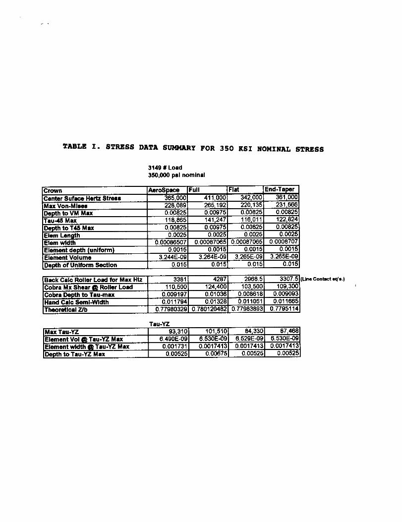
TABLE I. STRESS DATA SUMMARY FOR 350 KSI NOMINAL STRESS
3149 # Load
350,O00pslnominal
C rown
Center Suface Hertz StressMassVon-Mlses
Depth to VM MassTau-45 Max
Depth to T45 MassElem LengthElem width
Element depth (uniform)Element Volume
Depth of Uniform Section
AeroSpace365_000228r0890.00825
118,8650.00825
0.00250.00086507
0.00153.244E-09
0.015
Full
411,000265_1920.00975
141,2470.00975
0.0025
0.000870650.0015
3.264E-090.015
Fiat
342,000220,1350.00825
116t0110.00825
0.00250.00087O65
0.0015
3.265E-090.015
End-Taper361_00023116660.00825
122_8240.00825
0.00250.0008707
0.00153.265E-09
0.015
Back Calc Roller Load for MassHtzCobra Mx Shear (_ Roller Load
Cobra Depth to Tau-maxHand Calc Semi-WidthTheoretical 7Jb
3381
110,5000.0091970.011794
0.77980329
42871 2968.5124_4001 103,5000.01036J 0.008618
0.013281 0.0110510.7801204821 0.77983893
3307.5 I(LIn= Contacteq'=.)
109_300_0.009093 I0.011665 I
0.77951141
Tau-YZ
IM =IxTau-YZElement Vol (_ Tau-YZ Mass
IElement width (_ Teu-YZ Max
IDepth to Tau-YZ Mass
93,3106.490E-09
0.001731
101t5106.530E-09
0.0017413
841330 I
6.529E-09_0.0017413 I
0.005251
8714686.530E-090.0017413
0.005250.00525 0.00675

TABLE II. STRESS DATA SUMMARY FOR 275 KSI NOMINAL STRESS
1944.5 # Load
276,000 psi nominal
Center 8uface Hertz Stress 299,000 347,000 270,000 292,000Max Von-Misee 190,800 223,000 169,804 186,484
Depth to VM MaxTau-46 Max
Depth to T46 MaxElem LengthElem width
Element depth (uniform)Element Volume
0.0066101,6690.00660.0025
0.006840.0012
0.0078
119,8660.00780.0025
0.006840.0012
0.006690,0800.00660.0025
0.00684!0.0012
0.0066
99,2340.00660.0025
0.006840.0012
2.05E-09 2.05E-09 2.05E-09 2.05E-09
Depth of Uniform Section .012 .012 .012 .012
Back Calc Roller Load for Max Htz
Cobra Mx Shear _ Roller LoadCobra Depth to Tau-maxHand Calc Semi-WidthTheoretical Z/b
2268.5 3056 1850 2163.890,500 105,000 81,720 88,390
0.00753 0.00874 0.0068 0.007360.009681 0.011213 0.008724 0.009435
0.779422421 0.779452421 0.779458964 0.780074192
Tau-YZ
Max Tau-YZ
Element Vol (1_Tau-YZ MaxElement width _ Tau-YZ MaxDepth to Tau-YZ Max
73,3134.104E-090.001388
86,1354.120E-090.001373
64,7314.106E-090.001368
71,0234.106E-090.001368
0.0054 0.0066 0.0054 0.0054

TABLE III. STRESS DATA SUMMARY FOR 200 KSI NOMINAL STRESS
1028.5 # Load200,000 psi nominal
Center 8uface Hertz 8trees 228,600Max Von-Misee 149,302
Depth to VM Max 0.0055Tau-46 Max
Depth to T48 MaxElem LengthElem width
Element depth (uniform)Element Volume
76,2210.00550.0025
0.00055610.001
281,000 197,000 224,000177,781 124,219 141,4760.0065 0.0055 0.005595,165 65,640
0.00550.006575,3190.0055
0.0025 0.0025 0.00250.0004976 0.0004976 0.0004976
0.001 0.001 0.0011.39E-09 1.24E-09 1.24E-09 1.24E-09
Depth of Uniform Section .010 .010 .010 .010
Back Calc Roller Load for Max Htz
Cobra Mx 8hear _ Roller Load
Cobra Depth to Tau-maxHand Calc 8emi-Width
1330.869,320
0.005770.007399
Theoretical Z/b 0.779835113
Tau-YZ
Max Tau-YZ 55,7742.767E-09Element Vol _ Tau-YZ Max
Element width _ Tau-YZ Max
Depth to Tau-YZ Max
0.0011120.0035
2003.8 984.9 1273.485,060 59,630 '67,790
0.00708 0.004964 0.0056430.009079 0.006365 0.007238
0.779821566 0.779890024 0.779635258
69,792 48,355 55,5482.489E-09 2.844E-09 2.844E-090.0009953 0.0011375 0.0011375
0.0045 0.0035 0.0035

T_LE IV. 8TREBS-LIFE EXPONENTS - VON-MISES STRESS
2/13/97 Von-Mlses Stress
200 k 0.17189
275 k 0017140 0.017385
MO k 3.29510.-e 0.0016347 0.0030762 0.0010018
Zsrmslqt.-Well_l Mede:
0.06750
0.0018_)8 0.012275
Full crown End Taper
0.3426278
Lundber_lmgnm Model:
Full crownFlat proAle Aerospace crwn
0.012405 o.oeo2530.00024047 0.0038790
200 k 0,031450
278 k 0.0045238 0,0047708
k 1.00730e-7 0.00048314 0.00053643 0,0(XT25330
200k
276 k 0.20813
_60 k 0.00087100 0.00041618 3.94173e-5
Ionnldes-Harrts ModM: 819 Infinity = 123,250 psi
I Fktp_.o.o181so o1_._Pe='='_ F" ='_m54.224
I 1.23014e-5 0.10478 0.14778I s.s72_1o
End Taper
0083234
Ionnklu.Horlt= Model: 819 mflnny - Irt,ooo psi
T, GI550_Ie /M_opece ctwlrl Full cmwn,0 ,,,21 21 7I
I s.oe_ o.o_IOeI o.o,_7I ._,7=eo-o 0.ooo88295
End Taper
2832
End Taper
200 k 18.7421
21'8 k 0.050297
k 0.00054572 0.00011258
lonnMes-Harrls Model: Slg infinity - "/'9,750 psi
Flit pto_le Aerospace ¢rwn Full crown
100 k I 0.019458 4.7623 1.31787
ZT8 k I 8.2085e-5 0.025768 0.032541 0.030252D_O k 5.4872e_ 0.00064885 0,0(X)5018 0.00012975
Ionnides-Hllrrls Model: _ Infinity - 78,400 psi
End Taper9.7414
200 k 1.002714
278 k 0.028452 0.033950
350 k 0.0005_)35 0.00014005
275 k
[350 k
Fit p,_, A,ro-.i.¢. ¢_
0.019351 3.42867._1e-5 0.022682
8._1g_8 O.(:l_a08
Full crown End Taper8.7766
Ionnldee.,Harfls Model: Slg Infinity = 38,250 psi
Flat profile Aerospace crwn Full crown End Taper
0.016814 I 29306 I 0.12554 I 0.45822O.O(X)15.48.9 00080671 0,00_7536 0010679
3._-8 0 0006 i"06_ 000058371 000021886
Stress Life Exponent
Flat profile Aerospace Full cro_t End Taper
21 772754 10.95952 8,595411 12,46966
31.213368 10.10813 8.61212 14.30812
0 0 0 0
24.885814 1031365 8700604 12.38339
38.612455 10.44365 10.69005 14.71689
0 0 0 0
37.917057 28.7827 25.16974 38.66025
52.376424 24.01495 29.44222 42.97594
0 0 0 0
33.046228 19.61521 17.6695 25.69355
47.695705 17.99886 21.64958 30.59374
0 0 0 0
32.23037 18.44873 16.68548 23.99171
46.843636 17.11295 20.35292 28.63896
0 0 0 0
34.779517 27.52841
0 0
27.985639 18.07967 11.47832 16.34171
42.154575 12.85879 14.1185 19.49124
0 0 O 0

TABLE V. STRESS-LIFE EXPONENTS - MAX. SHEAR STRESS
2/13/97 Tau-45 ( max Shear )
'Zmatskl/-Wellxll Model:
2_k
275 k 0.015096
k 0.00084444
Z00k
275 k
Rat pme_ O._pece ©rim Full cro_
0.06745 01587230.011604 0.00_634 0.015885
2.0348_ 0.0013837 0.0028814
LuMbelll-IPllmOrwt Model:
0.0000444
0.00013057
4.M1
/ulro-iipece crvm Full crown
0.031340 0.0197330.0019764 0.0027945
0.0OO235O6 0,0OO29481
_,_rrls Model: _ Infinity- 1'2,500 pal
Flat prone Aero.epBce cnn Full crown
0._ 0.27053 4212.191._38e-6 0.14503 0.28511
3.7510o-ll 0.000_ J0_010173
Ionnldes4.1arrls Model: _ Infinity - 50,750 psi
lOOk
End Taper
0.060342 10.OO28325
0.O014178
End Toper127035.
0.32107
8.1812e_
FI_ pr_le _ ¢rw. Full crow.
200 k I 0.0077406 7.7349 3.5525
21'8 k J 1.62_ 0.023712 0.038018 0.045790NO k a.(_le-10 0.00032879 000019673 4.0104e-5
Ionn_rlr_ Model: _ Infihlt_ - 42,060 pal
End T-,per51071
pronk, Aero_o.ocr..200k I o.oo_1Ol 1.004o .r_o_
276k i 2.0287e-6 0.012643 0020119 0.02303k 2.1900_ 0.00032071 0.000230_8 59725e-5
Full craw_ End Taper8.24e3
I_mldes-I-_n.Js Model: SIg Inflnl_ - 2t,750 psi
Rat profile Aerospace cnvn Full crown
0.11466 0093275
0,0064612I 0.0086323
7.1170e-5
1.2188e-8 000028743
2(]Ok
275 k 0.0042272
350 k 000027639
End Taper
0.35078
0,(X)67356
000010727
Stress Life Exponent
Flat pro#te Aerospace Full crown End Taler
22.244748 12.91266 8.5673906 12.626899
43.362457 9.692382 8.55887 14.747378
0 0 0 0
15.524768 10.45684 8.9837669 7.6288807
16.498179 10.67511 11.276183 3.4_7429
0 0 0 0
"l
38.842892 7.482457 50.154207
54.553718 32.'8'122 39.8(X)239 53.044987
0 0 0 0
21.5117 20.946432 30.08320721.45017 26.381993 35.298127
0 0 0
32.400679 18.32013 17.728161 25.293711
35.9129 18.42192 22.403,562 29.85555
0 0 0 0
28.787968 12.68263 12.357419 17.29463
43.480624 13.67476 15.605575 20.755752
0 0 0 0
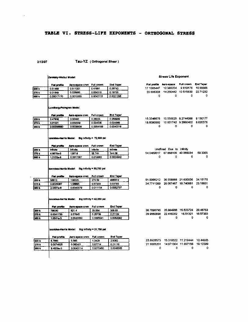
TABLE VI. STRESS-LIFE EXPONENTS - ORTHOGONAL STRESS
2/13/97 Tau-YZ ( Orthogonal Shear )
200k
275 k
360k
200k
228 k
360k
_OOk
Z"P5k
tl60k
200k
2"_k
lmOk
20Ok
2"t'6 k
360k
200k
278 k
Zllrltlky-Wllbui Model:
Flat proltle ,_ro-spece crmm
0.51484) 0.511351
i 0.01_9 0._I 0.00017170 0.0015555
Full crown End Taper
0.41691 0.29743
0.034318 0.19755
00042133 0.0021296
LundbMg-PIImlinm Modol:
Flit _ Aero-lpece crwn Full crown
0.47930 0.55403 0.26O250.01501 0.034559
0,00038680 0,0030838
End Taper0.288Q89
0.03453,5 0.02434_
0.(X)54186 0.0040316
i_nMes44anls Model: Slg Infinity" 72,500 psi
FIM pm41_ i/_nn pace crwn Full crown
I InAn_l Irlfinite4.8078e,,5 1267.8 55.741
1.0132_9 0.0017367 0+018862
End Taper
Infinite
344.00
0.0024942
Ionnkles4.klrlls Model: Sig Infinity - 50,750 pII
,u,,o+I . 273.5900025007 1.0_ 0.57203
144071)-6 0.0040379 0.011154
0.53793
0.0052737
IonnldesJ.larl'M Model: Sig Infinity - 42,050 psi
Flit profile Am'o-lpecl crwn Full crown
I 71_.90 621.4 25.0640.0041_ 0.3m4s 0.2s'r3g11,0s41_ o.oo43o5o
End Taper306.03
0.21184
0.00e5341 0.00520Q2
Ionnkles.Han'ls Model: SIg Infinity - 21,750 psi
mt pro_,i 0.7965 Aef_lpece cnNn Full crown5.505 1.3429
i 0.0074825 0.065401I 9.4839e-5 0.0043114
End Ta W2.5082
0.07714 0.21118
00070480 0.0048565
Stress Life Exponent
Flat profile Aero-space Full crown End T=l_r
17,1095447 12385054 9.819176 10.55566
22886308 14.250442 10515839 22.71232
0 0 0 0
15.3346678 10.550025 8.2744388 9.130177
18.6090992 10.831742 9.2860402 9.020378
0 0 0 0
Undfined Due to Infinity
54.0469517 67.688109 40.066034 59.3355
0 0 0 0
510066212 36.558888 21.600936 34.18178
34.7711389 28067467 19.740881 23.18831
0 0 0 0
389690795 25.984986 16.823724 23.46753
29.9880898 22.416262 16.51321 18.57303
0 0 0 0
23.8928573 15.319522 11.219444 13.44035
21.9005201 14.971364 11.997156 19.12399
0 0 0 0

TABLE VII. LAMINA WIDTH EFFECT VS. FATIGUE LIFE ERROR
(0.5"d x 0.5"1 + AEROSPACE CROWN)
Number of Lamina Width
Lamina Inch %
LI0 Life per LP Theoryhours % Diff.
4 0.125 25 7131 -21.9
5 0.i0 20 8436 - 7.7
i0 0.05 I0 9261 + 1.4
15 0.033 6.7 9174 + 0.4
20 0.025 5.0 9136 0.0
TABLE VIII. LAMINATED ROLLER MODEL LIFE COMPARISON
(0.5"d x 0.5"1 + AEROSPACE CROWN)
Nominal Max.
Hertz Stress
Roller BRG Pgm. SHABERTH
Load Stress Life Stress Life
(#) (psi) (hrs) (psi) (hrs)
200 ksi 1028.5 225,496 9263 224,809 9136
275 ksi 1944.5 296,910 965 296,408 924
350 ksi 3149.0 369,852 158 369,403 142
TABLE IX. FULLY CROWNED LAMINATED ROLLER COMPARISON
Nominal Max.
Hertz Stress
(ksi)
200
275
300
Max. Hertz Stress (psi)
20 Lamina 40 Lamina Ellip. Thy
% Difference
Stress Life
263,180 263,240 272,600 3.5% 37%
328,888 328,940 337,000 2.5% 24.5
397,760 -- 395,700 OVERSPILL


![Untersuchungen zur Komplexität der Berechnung eines ...€¦ · Kintali, Poplawski, Rajamaran, Sundaram und Teng [1], in welchem die PPAD-Vollständigkeit des stark verwandten Problems](https://img.pdfslide.net/doc/110x75/5e15b992d8e87778ea5f7c0d/untersuchungen-zur-komplexitt-der-berechnung-eines-kintali-poplawski-rajamaran.jpg)