Embed Size (px)
Citation preview

K-750 Drain CleaningMachine
WARNING!Read this Operator’s Manualcarefully before using thistool. Failure to understandand follow the contents ofthis manual may result inelectrical shock, fire and/orserious personal injury.
Drain Cleaner Manual
99 Washington Street Melrose, MA 02176 Phone 781-665-1400Toll Free 1-800-517-8431
Visit us at www.TestEquipmentDepot.com

Table of ContentsRecording Form for Machine Serial Number ..............................................................................................................1
Safety Symbols ..............................................................................................................................................................2
General Safety RulesWork Area Safety ........................................................................................................................................................2Electrical Safety...........................................................................................................................................................2Personal Safety ...........................................................................................................................................................2Tool Use and Care ......................................................................................................................................................3Service ........................................................................................................................................................................3
Drain Cleaner WarningsDrain Cleaner Safety ...................................................................................................................................................3
Description, Specifications and Standard EquipmentDescription ..................................................................................................................................................................4Specifications ..............................................................................................................................................................4Standard Equipment....................................................................................................................................................5
Machine Assembly ........................................................................................................................................................5Connecting/Disconnecting 5/8" and 3/4" Drum Machine Cable Couplings .....................................................................6
Pre-Operation Inspection..............................................................................................................................................7
Machine and Work Area Set-Up ...................................................................................................................................9
Operating Instructions ................................................................................................................................................11Operation...................................................................................................................................................................12Feeding The Cable Into The Drain ............................................................................................................................12Cleaning The Drain ...................................................................................................................................................13Working The Blockage ..............................................................................................................................................13Handling A Stuck Tool...............................................................................................................................................14Freeing A Stuck Tool.................................................................................................................................................14Retrieving The Cable.................................................................................................................................................14Using Machine With A Front Guide Hose..................................................................................................................14Adding Additional Cable ............................................................................................................................................15Drum Removal and Installation .................................................................................................................................15
Maintenance Instructions ...........................................................................................................................................16Cleaning ....................................................................................................................................................................16Cables .......................................................................................................................................................................16AUTOFEED...............................................................................................................................................................16Lubrication.................................................................................................................................................................16Front Guide Hose ......................................................................................................................................................16
Accessories .................................................................................................................................................................17
Machine Storage ..........................................................................................................................................................17
Service and Repair ......................................................................................................................................................17
Disposal........................................................................................................................................................................18
Troubleshooting ..........................................................................................................................................................18
Lifetime Warranty..........................................................................................................................................Back Cover
*Original Instructions - English
ii
K-750 Drain Cleaning Machine

K-750 Drain Cleaning Machine
Drain Cleaner
K-750 Drain Cleaning MachineRecord Serial Number below and retain product serial number which is located on nameplate.
SerialNo.

2
K-750 Drain Cleaning Machine
General Safety Rules*
WARNINGRead and understand all instructions. Failure to fol-low all instructions listed below may result in elec-tric shock, fire, and/or serious injury.
SAVE THESE INSTRUCTIONS!
Work Area Safety• Keep work area clean and well lit. Cluttered benches
and dark areas invite accidents.
• Do not operate power tools in explosive atmo-spheres, such as in the presence of flammableliquids, gases, or dust. Power tools create sparkswhich may ignite the dust or fumes.
• Keep bystanders, children, and visitors away whileoperating a power tool. Distractions can cause you tolose control.
Electrical Safety• Grounded tools must be plugged into an outlet
properly installed and grounded in accordancewith all codes and ordinances. Never remove thegrounding prong or modify the plug in any way. Donot use any adapter plugs. Check with a qualified
electrician if you are in doubt as to whether the out-let is properly grounded. If the tool should electricallymalfunction or break down, grounding provides a lowresistance path to carry electricity away from the user.
• Avoid body contact with grounded surfaces suchas pipes, radiators, ranges and refrigerators. Thereis an increased risk of electric shock if your body isgrounded.
• Do not expose power tools to rain or wet condi-tions. Water entering a power tool will increase the riskof electric shock.
• Do not abuse the cord. Never use the cord to carrythe tool or pull the plug from an outlet. Keep cordaway from heat, oil, sharp edges or moving parts.Replace damaged cords immediately. Damagedcords increase the risk of electric shock.
• When operating a power tool outside, use an out-door extension cord marked “W-A” or “W”. Thesecords are rated for outdoor use and reduce the risk ofelectric shock.
Personal Safety• Stay alert, watch what you are doing and use com-
mon sense when operating a power tool. Do notuse a tool while you are tired or under the influence
Safety SymbolsIn this operator’s manual and on the product, safety symbols and signal words are used to communicate important safetyinformation. This section is provided to improve understanding of these signal words and symbols.
This is the safety alert symbol. It is used to alert you to potential personal injury hazards. Obey all safety messages that follow thissymbol to avoid possible injury or death.
DANGER indicates a hazardous situation which, if not avoided, will result in death or serious injury.
WARNING indicates a hazardous situation which, if not avoided, could result in death or serious injury.
CAUTION indicates a hazardous situation which, if not avoided, could result in minor or moderate injury.
NOTICE indicates information that relates to the protection of property.
This symbol means read the operator’s manual carefully before using the equipment to reduce the risk of injury. The operator’smanual contains important information on the safe and proper operation of the equipment.
This symbol means always wear safety glasses with side shields or goggles when handling or using this equipment to reducethe risk of eye injury.
NOTICE
This symbol indicates the risk of hands, fingers or other body parts being caught, wrapped or crushed in the drain cleaningcable.
This symbol indicates a risk of electrical shock.
DANGER
WARNING
CAUTION
This symbol indicates the risk of entanglement in a belt and pulley.
* The text used in the General Safety Rule section of this manual is verbatim, as required, from the applicable UL/CSA 745 1st edition standard. This section con-tains general safety practices for many different types of power tools. Not every precaution applies to every tool, and some do not apply to this tool.

3
of drugs, alcohol or medication. A moment of inat-tention while operating power tools may result in seri-ous personal injury.
• Dress properly. Do not wear loose clothing or jew-elry. Contain long hair. Keep your hair, clothing andgloves away from moving parts. Loose clothes,jewelry or long hair can be caught in moving parts.
• Avoid accidental starting. Be sure switch is OFF be-fore plugging in. Carrying power tools with your fingeron the switch or plugging in power tools that have theswitch ON invites accidents.
• Remove adjusting keys or wrenches before turningthe tool ON. A wrench or a key left attached to a rotat -ing part of the power tool may result in personal injury.
• Do not overreach. Keep proper footing and balanceat all times. Proper footing and balance enables bet-ter control of the tool in unexpected situations.
• Use safety equipment. Always wear eye protec-tion. Dust mask, non-skid safety shoes, hard hat, orhearing protection must be used for appropriate condi-tions.
Tool Use and Care• Use clamps or other practical way to secure and
support the workpiece to a stable platform. Holdingthe work by hand or against your body is unstableand may lead to loss of control.
• Do not force the tool. Use the correct tool for yourapplication. The correct tool will do the job betterand safer at the rate for which it was designed.
• Do not use tool if the switch does not turn it ON andOFF. Any tool that cannot be controlled with the switchis dangerous and must be repaired.
• Disconnect the plug from the power source be-fore making any adjustments, changing accessor-ies, or storing the tool. Such preventive safety mea-sures reduce the risk of starting the tool accidentally.
• Store idle tools out of the reach of children andother untrained persons. Tools are dangerous inthe hands of untrained users.
• Maintain tools with care. Keep cutting tools sharpand clean. Properly maintained tools with sharp cuttingedges are less likely to bind and are easier to control.
• Check for misalignment or binding of moving parts,breakage of parts and any other condition thatmay affect the tool’s operation. If damaged, have thetool serviced before using. Many accidents arecaused by poorly maintained tools.
K-750 Drain Cleaning Machine
• Use only accessories that are recommended by themanufacturer for your model. Accessories that maybe suitable for one tool, may become hazardous whenused on another tool.
Service• Tool service must be performed only by qualified
repair personnel. Service or maintenance performedby unqualified personnel could result in a risk of injury.
• When servicing a tool, use only identical replace-ment parts. Follow instructions in the Maintenancesection of this manual. Use of unauthorized parts orfailure to follow Maintenance Instructions may create arisk of electrical shock or injury.
Drain Cleaner Safety WarningsWARNING
This section contains important safety informationthat is specific to this tool.
Read these precautions carefully before using the K-750 Drain Cleaning Machine to reduce the risk ofelectrical shock or other serious personal injury.
SAVE ALL WARNINGS AND INSTRUCTIONSFOR FUTURE REFERENCE!
Keep this manual with the machine for use by the operator.
Drain Cleaner Safety• Only wear RIDGID® drain cleaning gloves or mitts
(“gloves”). Never grasp the rotating cable withany thing else, including other gloves or a rag.They can become wrapped around the cable, causinghand injuries. Only wear latex or rubber gloves underRIDGID drain cleaner gloves. Do not use damageddrain cleaning gloves.
• Never operate machine with the belt guard re-moved. Fingers can be caught between the belt andpulley.
• Do not allow the cutter to stop turning while themachine is running. This can overstress the cableand may cause twisting, kinking or breaking of thecable. Twisting, kinking or breaking cable may causestriking or crushing injuries.
• Keep gloved hand on the cable whenever the ma-chine is running. This provides better control of thecable and helps prevent twisting, kinking and breakingof the cable. Twisting, kinking or breaking cable maycause striking or crushing injuries.
• Position machine within three feet of the drain inlet

4
K-750 Drain Cleaning Machine
Description, Specifications andStandard EquipmentDescriptionThe RIDGID® K-750 Drain Cleaning Machine will cleandrain lines 3" to 8" in diameter and 200 feet in length de-pending on size of cable. Corrosion resistant cable drumholds 100 feet of 3/4" diameter cable or 125 feet of 5/8" di-ameter cable. Cable spins at 200 RPM.
The drum is belt-driven by a 1/2 HP electric motor thathas a grounded electrical system. An integral GroundFault Interrupter (GFCI) is built into the line cord. A pneu-matic foot switch provides ON/OFF control of the motor. A“kickstand” base is provided for machine stability during op-eration.
The cable has a quick change coupling system for con-necting or disconnecting tools. An optional AUTOFEED ad-vances or retracts the cable at a rate up to 20 feet perminute. A manual feed option is also available.
Specifications
Line Capacity ..................See Following Chart.
Drum Capacity...............100' of 3/4" Cable or 125' of 5/8" Cable
Motor Type ......................Induction
Motor Rating115V Motor ..................115VAC Single Phase
6.5 A, 60Hz230/240V Motor ...........230/240VAC
3.6 A, 50Hz, 550W
No Load Speed ...............200 r/min (RPM)
Weight (Machine Only)...95 lbs.
DimensionsLength..........................26"Width............................21"Height ..........................43"
or properly support exposed cable when the dis-tance exceeds three feet. Greater distances cancause control problems leading to twisting, kinking orbreaking of the cable. Twisting, kinking or breakingcable may cause striking or crushing injuries.
• One person must control both the cable and thefoot switch. If the cutter stops rotating, the operatormust be able to turn the machine motor off to preventtwisting, kinking and breaking of the cable. Twisting,kinking or breaking cable may cause striking or crush-ing injuries.
• Do not operate the machine in REV (reverse) rota-tion except as described in this manual. Operatingin reverse can result in cable damage and is used toback the tool out of blockages.
• Keep hands away from rotating drum and guidetube. Do not reach into drum unless machine is un-plugged. Hand may be caught in the moving parts.
• Do not wear loose clothing or jewelry. Keep yourhair and clothing away from moving parts. Looseclothing, jewelry or hair can be caught in moving parts.
• Always use appropriate personal protective equip-ment while handling and using drain cleaning e -quip ment. Drains may contain chemicals, bacteriaand other substances that may be toxic, infectious,cause burns or other issues. Appropriate personalprotective equipment always includes safety glass -es and RIDGID drain cleaning gloves, and may in-clude equipment such as latex or rubber gloves, faceshields, goggles, protective clothing, respirators andsteel-toed footwear.
• Practice good hygiene. Use hot, soapy water towash hands and other body parts exposed to draincontents after handling or using drain cleaning equip-ment. Do not eat or smoke while operating or handlingdrain cleaning equipment. This will help prevent con-tamination with toxic or infectious material.
• Do not operate this machine if operator or ma-chine is standing in water. Operating machine whilein water increases the risk of electrical shock.
• Only use drain cleaning machine to clean drains ofrecommended sizes according to these instruc-tions. Other uses or modifying the drain cleaning ma-chine for other applications may increase the risk ofinjury.
The EC Declaration of Conformity (890-011-320.10) will accompany this manual as a separate booklet when re-quired.
Cable Size Recommended Lineand Type Size and Reach
Line Size Reach5/8" Cable 3" to 6" 150'3/4" Cable 4" to 8" 200'

Figure 1 – K-750 Drain Cleaning Machine with AUTOFEED
Figure 2 – Machine Serial Number
The machine serial number is located on the rear drumsupport. The last 4 digits indicates the month and year ofthe manufacture. (04 = month, 10 = year).
Standard EquipmentAll K-750 Drain Cleaning Machines come with one pair ofRIDGID Drain Cleaning Gloves.
This machine is made to clean drains. If prop-erly used it will not damage a drain that is in good condi-tion and properly designed, constructed and maintained.If the drain is in poor condition, or has not been properlydesigned, constructed and maintained, the drain cleaningprocess may not be effective or could cause damage tothe drain. The best way to determine the condition of a
drain before cleaning is through visual inspection with acamera. Improper use of this drain cleaner can damagethe drain cleaner and the drain. This machine may notclear all blockages.
Machine AssemblyWARNING
To reduce the risk of serious injury during use, followthese procedures for proper assembly.
FOR/OFF/REV switch should be OFF and machine un-plugged before assembly.
Installing Handles
1. Remove the bolts and nuts retaining the belt guardbracket to the machine frame, remove belt guard.
2. Loosely assemble loading wheel to handles with pro-vided bolts (see Figure 3).
Figure 3 – Handle Installation and Belt Guard Adjustment
5
K-750 Drain Cleaning Machine
Belt Guard
AUTOFEED
Guide Tube
Loading Wheel
Handles
FOR/OFF/REVSwitch
Foot Switch
Drum
Kickstand
Motor
GFCI Cord
NOTICE
Date Code
Loading Wheel
Belt GuardGap
1/4" MAX.
Handles
Belt GuardFasteners

6
3. Insert handles into machine frame and install boltsthrough belt guard bracket, machine frame and han-dle. Install nuts to retain bolts, do not tighten.
4. Firmly tighten bolts holding loading wheel to han-dles.
5. Adjust gap between guard and drum to less than1/4". Firmly tighten belt guard bracket bolts. Confirmthat gap between belt guard and drum is less than 1/4"to prevent fingers and other objects from being pulledinto the belt and pulley. Adjust if necessary.
Installing Cable
Do not remove the bands or cables from the cable car-ton. The cable is under tension and can whip or strike ifreleased.
Manual Cable Installation – this can be used for bothManual and AUTOFEED units.
1. Retrieve male coupling end of cable through thecenter hole of the carton and pull approximately 6' ofcable from the carton.
2. Connect the male coupling of the cable to the pigtailcoupling (See Figure 4). Confirm connection is secure.
3. Pull short sections of cable from the carton and man-ually feed into the drum. Do not turn machine ON.
AUTOFEED Cable Installation
1. Retrieve male coupling end of cable through centerhole of carton and pull cable from carton. Lay cableout straight in a flat area (such as an empty paved
Connecting/Disconnecting 5/8" and 3/4" Drum Machine Cable Couplings
Keep couplings clean and lubricated. Plunger pin must move freely and fully extend to secure connection.
New style – Plunger pinScrewdriver required.
Connecting
1. Slide the couplings together. If needed, depress plungerpin.
2. Confirm connection is secure. (plunger pin fully ex-tended).
Disconnecting
1. Insert the screwdriver to depress the plunger pin.2. Push the couplings apart until the male coupling con-
tacts the screwdriver.3. Remove the screwdriver and push the couplings apart.
1 2
Old style – Rotating pinScrewdriver required.
Connecting
1. Slide the couplings together. 2. Rotate pin so hash mark is away from end of cable (to-
wards “L” stamped on coupling). Confirm connection issecure.
Disconnecting
1. Rotate pin so hash mark is towards end of cable (awayfrom “L” stamped on coupling).
2. Push the couplings apart.
1 3a 3b2
Hash Mark
Figure 4
K-750 Drain Cleaning Machine

Pre-Operation InspectionWARNING
Before each use, inspect your drain cleaning ma-chine and correct any problems to reduce the risk ofserious injury from electric shock, twisted or brokencables, chemical burns, infections and other causesand prevent drain cleaner damage.
Always wear safety glasses, RIDGID drain cleaninggloves, and other appropriate protective equipmentwhen inspecting your drain cleaner. For extra pro-tection from chemicals and bacteria on the equip-ment, wear latex, rubber or other liquid barriergloves under the RIDGID drain cleaning gloves.
1. Inspect the RIDGID drain cleaning gloves or mitts(“gloves”). Make sure they are in good condition withno holes, tears or loose sections that could be caughtin the rotating cable. It is important not to wear im-proper or damaged gloves. The gloves protect yourhands from the rotating cable. If the gloves are notRIDGID drain cleaning gloves or are damaged orworn out, do not use machine until RIDGID draincleaning gloves are available. See Figure 6.
Figure 6 – RIDGID Drain Cleaning Gloves – Leather, PVC
2. Make sure that the drain cleaning machine is un-plugged and inspect the power cord, Ground FaultCircuit Interrupter (GFCI) and plug for damage. If theplug has been modified, is missing the groundingprong or if the cord is damaged, to avoid electricalshock, do not use the machine until the cord hasbeen replaced by a qualified repair person.
3. Clean any oil, grease or dirt from all equipment han-dles and controls. This helps prevent the machineor control from slipping from your grip.
7
parking lot or driveway) with no obstructions or itemsthat could become wrapped around the cable.
2. When using an AUTOFEED to load cable, the rotatingcable will tend to walk sideways. To prevent this,place suitable stops (such as wood blocks) on eitherside of the cable at 10 foot intervals.
3. After properly inspecting and setting up the draincleaner, attach the cable to the pigtail as shown inFigure 4. Make sure that no one is in the area aroundthe cable. Tighten the AUTOFEED knob so that theroller touches the cable plus one additional turn. Withthe FOR/OFF/REV switch in the FOR position, pressthe foot switch to start the drum turning. Move the feedhandle in the opposite direction of the cable rotation tofeed the cable into the drum.
4. When 10' of cable is left outside of the drum, step offthe foot switch and move the FOR/OFF/REV switch toOFF. Loosen the AUTOFEED knob and manuallyfeed the remaining cable into the drum. Do not use theAUTOFEED to put all of the cable in the drum. Thecable end can whip around and cause serious injury.
Attaching Front Guide Hose (Optional AccessoryFor Use With AUTOFEED)
1. Pull approximately 4' of cable from the drum.
2. Slide Front Guide Hose over the cable, adapter endfirst. Pull plunger pin head up and place adapter overthe mounting collar on the AUTOFEED. Make sureplunger pin locks into the hole in the mounting collar.
Figure 5 – Attaching Front Guide Hose To AUTOFEED
K-750 Drain Cleaning Machine
Plunger Pin
Hole
Guide Hose

8
4. Make sure the foot switch is attached to the draincleaning machine. Do not operate the machine with-out the foot switch.
5. Inspect the drain cleaning machine for the followingitems:• Proper assembly and completeness• Any broken, worn, missing, mis-aligned or binding
parts• Smooth and free movement of the AUTOFEED
handle throughout range. Rotate the drum andmake sure that it turns freely without binding.
• Presence and readability of the warning label (seeFigure 7).
• Presence and proper adjustment of the belt guard.Belt guard should be adjusted so that the gap be-tween the guard and the drum is no more than 1/4".(See Figure 3.)
• Any condition which may prevent safe and normaloperation.
If any problems are found, do not use the draincleaner until the problems have been repaired.
Figure 7 – Warning Label
6. Clean any debris from the cable and cutting tools.Inspect cables for wear and damage. Inspect for:• Obvious flats worn into the outside of the cable
(cable is made from round wire and the profileshould be round).
• Multiple or excessively large kinks (slight kinks up to15 degrees can be straightened).
• Space between cable coils indicating that the cablehas been deformed by stretching, kinking, or runningin reverse (REV).
• Excessive corrosion from storing wet or exposure todrain chemicals.
All of these forms of wear and damage weaken thecable and make cable twisting, kinking or breakingmore likely during use. Replace worn and damagedcable before using drain cleaner.
Make sure the cable is fully retracted with no morethan 6" of cable outside of the machine. This willprevent whipping of the cable at start up.
7. Inspect the tools for wear and damage. If necessary,replace prior to using the drain cleaning machine.Dull or damaged cutting tools can lead to binding,cable breakage, and slow the drain cleaning pro-cess.
8. Make sure that the FOR/OFF/REV switch is set to theOFF position.
9. With dry hands, plug cord into properly groundedoutlet. Test the GFCI provided in the electrical cord toinsure that it is operating correctly. When the testbutton is pushed in, the indicator light should go off.Reactivate by pushing the reset button in. If the indi-cator light goes on, the GFCI is functioning properly.If GFCI is not functioning properly, unplug the cord anddo not use the drain cleaning machine until the GFCIhas been repaired.
Figure 8 – Proper Drum Rotation (FOR Switch Position)
K-750 Drain Cleaning Machine
FORWARDDrum
Rotation
9
10. Move the FOR/OFF/REV switch into the FOR posi-tion. Press the foot switch and note the direction of ro-tation of the drum. If the foot switch does not controlthe machine operation, do not use the machine untilthe foot switch has been repaired. The drum shouldrotate counter-clockwise when viewed from the frontof the drum, and will match the drum direction shownon the warning label (Figure 7) and shown in Figure 8.Release the foot switch and let the drum come to acomplete stop. Place the FOR/OFF/REV switch intothe REV position, and repeat above testing to confirmthat the drain cleaner operates properly in reverse. Ifthe rotation is not correct, do not use the machine untilit has been repaired.
11. With the inspection complete, move the FOR/OFF/ -REV switch into the OFF position and, with dry hands,unplug the machine.
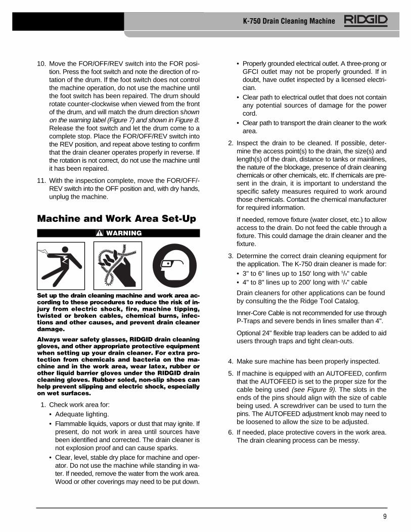
Machine and Work Area Set-UpWARNING
Set up the drain cleaning machine and work area ac-cording to these procedures to reduce the risk of in-jury from electric shock, fire, machine tipping,twisted or broken cables, chemical burns, infec-tions and other causes, and prevent drain cleanerdamage.
Always wear safety glasses, RIDGID drain cleaninggloves, and other appropriate protective equipmentwhen setting up your drain cleaner. For extra pro-tection from chemicals and bacteria on the ma-chine and in the work area, wear latex, rubber orother liquid barrier gloves under the RIDGID draincleaning gloves. Rubber soled, non-slip shoes canhelp prevent slipping and electric shock, especiallyon wet surfaces.
1. Check work area for:• Adequate lighting.• Flammable liquids, vapors or dust that may ignite. If
present, do not work in area until sources havebeen identified and corrected. The drain cleaner isnot explosion proof and can cause sparks.
• Clear, level, stable dry place for machine and oper-ator. Do not use the machine while standing in wa -ter. If needed, remove the water from the work area.Wood or other coverings may need to be put down.
K-750 Drain Cleaning Machine
• Properly grounded electrical outlet. A three-prong orGFCI outlet may not be properly grounded. If indoubt, have outlet inspected by a licensed electri-cian.
• Clear path to electrical outlet that does not containany potential sources of damage for the powercord.
• Clear path to transport the drain cleaner to the workarea.
2. Inspect the drain to be cleaned. If possible, deter-mine the access point(s) to the drain, the size(s) andlength(s) of the drain, distance to tanks or mainlines,the nature of the blockage, presence of drain cleaningchemicals or other chemicals, etc. If chemicals are pre-sent in the drain, it is important to understand thespecific safety measures required to work aroundthose chemicals. Contact the chemical manufacturerfor required information.
If needed, remove fixture (water closet, etc.) to allowaccess to the drain. Do not feed the cable through afixture. This could damage the drain cleaner and thefixture.
3. Determine the correct drain cleaning equipment forthe application. The K-750 drain cleaner is made for:• 3" to 6" lines up to 150' long with 5/8" cable• 4" to 8" lines up to 200' long with 3/4" cable
Drain cleaners for other applications can be found by consulting the the Ridge Tool Catalog.
Inner-Core Cable is not recommended for use through P-Traps and severe bends in lines smaller than 4".
Optional 24" flexible trap leaders can be added to aid users through traps and tight clean-outs.
4. Make sure machine has been properly inspected.
5. If machine is equipped with an AUTOFEED, confirmthat the AUTOFEED is set to the proper size for thecable being used (see Figure 9). The slots in theends of the pins should align with the size of cablebeing used. A screwdriver can be used to turn thepins. The AUTOFEED adjustment knob may need tobe loosened to allow the size to be adjusted.
6. If needed, place protective covers in the work area.The drain cleaning process can be messy.

10
K-750 Drain Cleaning Machine
Figure 9 – AUTOFEED Size Setting
7. Take the drain cleaning machine to the work areaalong the clear path. If the machine needs to belifted, use proper lifting techniques. Use care movingequipment up and down stairs, and be aware of pos-sible slip hazards. Wear appropriate footwear to helpprevent slips.
8. Position the drain cleaning machine so that the K-750cable outlet is within 3 feet of the drain access. Great -er distances from the drain access increases therisk of the cable twisting or kinking. If the machinecannot be placed with the cable outlet within 3' of thedrain access, extend the drain access back to within3' of the cable outlet with similar sized pipe and fit-tings. Improper cable support can allow the cable tokink and twist and can damage the cable or injure theoperator. See Figure 10. If using front guide hose,place machine so that at least 6" of guide hose can beplaced in drain opening.
Figure 10 – Example of Extending Drain to Within 3' ofCable Outlet
9. Tilt the machine forward and use your foot to rotateone kickstand at a time to the backside of the wheel.The machine should firmly rest on the kickstands.The kickstands stabilize the machine and help preventtipping or walking during use. If working on soft ground,it may be necessary to place wood or other solid ma-terial under the drain cleaner for proper support.
Figure 11 – Setting Kickstands
10. Evaluate the work area and determine if any barriers are needed to keep bystanders away from the drain cleaner and work area. The drain cleaning process can be messy and bystanders can distract the operator.
11. Select proper tool for the conditions.If the nature of the obstruction is unknown, it is good practice to use a straight or bulb auger to explore the obstruction and retrieve a piece of the obstruction for inspection.Once the nature of the obstruction is known, an ap-propriate tool can be selected for the application. A good rule of thumb is to start by running the smallest available tool through the blockage to allow the backed up water to start flowing and carry away the debris and cuttings as the drain is cleaned. Once the drain is open and flowing, other tools appropriate for the blockage can be used. Generally, the largest tool used should be no bigger than the inside diameter of the drain minus one inch.Proper tool selection depends on the specific cir-cumstances of each job and is left to the users’ judgement.A variety of other cable attachments are available and are listed in the Accessories section of this manual. Other information on cable attachments can be found in the RIDGID Catalog.
AUTOFEED Size Setting

11
K-750 Drain Cleaning Machine
12. Securely install tool on the end of the cable (SeeFigure 4). If the connection is not secure, the cuttingtool may fall off in use.
13. Position the foot switch for easy accessibility. Youmust be able to hold and control the cable, control thefoot switch, and reach the FOR/OFF/REV switch.
14. Confirm that the FOR/OFF/REV switch is in the OFFposition.
15. Run the cord along the clear path. With dry handsplug the drain cleaner into a properly grounded outlet.Keep all connections dry and off the ground. If thepower cord is not long enough, use an extensioncord that:• Is in good condition.• Has a three prong plug similar to that supplied on
the drain cleaner.• Is rated for outdoor use and contains a W or W-A in
the cord designation (i.e. SOW), or complies withH05VV-F, H05RN-F types or IEC type design(60227 IEC 53, 60245 IEC 57).
• Has sufficient wire size (16 AWG (1.5mm2) for 50'(15.2m) or less, 14 AWG (2.5mm2) for 50' – 100'(15.2m – 30.5m) long). Undersized wires can over-heat, melting the insulation or causing a fire or otherdamage.
When using an extension cord, the GFCI on thedrain cleaner does not protect the extension cord. Ifthe outlet is not GFCI protected, it is advisable touse a plug in type GFCI between the outlet and theextension cord to reduce the risk of shock if there is afault in the extension cord.
Operating InstructionsWARNING
Always wear eye protection to protect your eyesagainst dirt and other foreign objects.Only wear RIDGID drain cleaning gloves or mitts.Never grasp the rotating cable with anything else, in-cluding a glove or a rag. They can become wrappedaround the cable, causing serious injury.
When cleaning drains that might contain hazardouschemicals or bacteria, wear appropriate protectiveequipment, such as goggles, face shields or respi-rators, to prevent burns and infections. For extra pro-
tection from chemicals and bacteria on the ma-chine and in the work area, wear latex, rubber orother liquid barrier gloves under the RIDGID draincleaning gloves. Rubber soled, non-slip shoes canhelp prevent slipping and electric shock, especiallyon wet surfaces.
Follow operating instructions to reduce the risk ofinjury from twisted or broken cables, cable endswhipping around, machine tipping, chemical burns,infections and other causes.
1. Make sure that machine and work area is properly setup and that the work area is free of bystanders andother distractions.
2. Pull cable out of drum and feed into drain. If needed,loosen AUTOFEED knob. Push cable as far into drainas it will go. At least one foot (.3 m) of cable must bein drain so that the end of the cable will not come outof the drain and whip around when the machine isstarted.
Directly route the cable from the outlet of the machineto the drain opening, minimizing exposed cable andchanges in direction. Do not tightly bend the cable –this can increase the risk of twisting or breaking.
Figure 12 – In Operating Position, Manually FeedingCable
3. Assume a proper operating position:• Be sure you can control the ON/OFF action of the
foot switch and can quickly release the foot switchif needed. Do not press foot switch yet.
• Be sure that you have good balance, do not have toover reach, and cannot fall on the foot switch, draincleaning machine, the drain or other hazards.

12
K-750 Drain Cleaning Machine
• You must be able to place at least one hand on thecable at all times to control and support the cable.
• You must be able to reach the FOR/OFF/REVswitch.
This operating position will help to maintain control ofthe cable and machine. See Figure 12.
4. Move the FOR/OFF/REV switch to the FOR (FOR-WARD) position. Do not depress the foot switch yet.FOR/OFF/REV refers to the drum/cable rotation andnot to the direction of cable movement. Do not rotatethe cable in reverse except as specifically describedin these instructions. Running the drain cleaner inREV can damage the cable.
OperationThe K-750 Drain Cleaning Machine is available in twodifferent feed configurations, either manual feed or AUTO -FEED. A K-750 supplied with the AUTOFEED can eitherfeed the cable with the AUTOFEED (feed lever position) orby manually pulling the cable from the drum and feeding itinto the drain. With the AUTOFEED you can switch backand forth between operating methods as needed. A K-750without the AUTOFEED can only be used manually.
Feeding The Cable Into The DrainManual Operation
Confirm that at least one foot (.3 m) of cable is in the drain.Grasp the exposed cable with both gloved hands equallyspaced and pull 6"-12" of cable out of the drum so thatthere is a slight bow in the cable. Gloved hands must beon the cable to control and support the cable. Impropercable support can allow the cable to kink or twist and candamage the cable or injure the operator. Make sure thatthe cable outlet of the drain cleaner is within 3' of the drainopening.
Depress the foot switch to start the machine. The personcontrolling the cable must also control the foot switch. Donot operate the drain cleaner with one person controllingthe cable and another person controlling the foot switch.This can lead to twisting, kinking and breaking of thecable. Feed the rotating cable into the drain. The rotatingcable will work its way into the drain as you push on thecable with gloved hands. Do not allow the cable to build upoutside the drain, bow or curve. This can allow the cableto twist, kink or break.
When the cable has been fed into the drain opening,pull 6"-12" more cable from the drum and continue feed-ing the rotating cable into the drain.
AUTOFEED Operation
Confirm that at least one foot (.3 m) of cable is in the drain.Tighten the AUTOFEED knob (Figure13) so that the roller
touches the cable plus one additional turn. Do no over-tighten the knob – this can cause premature failure of theAUTO FEED or cable.
Grasp near the center of the exposed length of cablewith a gloved hand. Gloved hand must be on the cable tocontrol and support the cable. Improper cable support canallow the cable to kink or twist and can damage the cableor injure the operator. Make sure that the cable outlet ofthe drain cleaner is within 3' of the drain opening. Place theother hand on the AUTOFEED lever. AUTOFEED levershould be in neutral (Vertical) position (see Figure 13).
See “Using Machine With A Front Guide Hose” if using aguide hose.
Figure 13 – AUTOFEED Lever Positions(Cable Turning In FOR Direction)
NOTE: Rate of cable advance or retrieve varies byhandle movement from neutral.
Depress the foot switch to start the machine. The personcontrolling the cable must also control the foot switch. Donot operate the drain cleaner with one person controllingthe cable and another person controlling the foot switch.This can lead to twisting, kinking and breaking of thecable. With the cable rotating, move the AUTOFEEDcontrol handle in the same direction that the cable rotates.This will cause the cable to feed out of the machine. Thefurther the control handle from the neutral position, thefaster the cable will be fed (up to 20' per minute, maxi-mum). The rotating cable will work into the drain as youcontrol the cable with your gloved hand. Do not allowthe cable to build up outside the drain, bow or curve.This can allow the cable to twist, kink or break.
Neutral
Full Advance
Full Retrieve
FORRotation
AUTOFEEDKnob

13
K-750 Drain Cleaning Machine
Figure 14 – Operating the K-750 using the AUTOFEED
If it is difficult to get the cable through a trap or other fit-ting, the following methods or combinations of methodscan be used.
• Sharp thrusts of the cable, both with and withoutthe cable rotating, can help the cable through atrap.
• In some cases with the switch in the OFF position,rotating the drum by hand can change the orien-tation of the cutter to allow it to more easily ne-gotiate the fitting.
• Run the drain cleaner in REV (REVERSE) rotationfor several seconds while pushing on the cable.Only do this long enough to get the cable startedthrough the trap. Running the cable in reverse candamage the cable.
• Use a flexible leader between the tool and thecable.
• If these options don’t work, consider using a smallerdiameter or more flexible cable, or a different draincleaner.
Cleaning The DrainAs you feed the cable into the drain, you may see thecable slow down or build up outside the drain. Alwayskeep your hands on the cable. You may feel the cablestart to wind or load up (this may feel like the cable is start-ing to twist or squirm). This may be a transition in the drain(trap, elbow, etc.), build up in the drain (grease, etc.) or theactual blockage. Feed the cable slowly and carefully. Do
not let cable build up outside the drain. This can cause thecable to twist, kink or break.
Pay attention to the amount of cable that has been fed intothe drain. Feeding cable into a larger drain, septic tank orsimilar transition may cause the cable to kink or knotand prevent removal from the drain. Minimize the amountof cable fed into the transition to prevent problems. Eachwrap of the cable in the drum is approximately four feetlong. If using 5/8" cable with a 3/4" pigtail, do not feed theconnection through the AUTOFEED. This could damagethe AUTOFEED.
If an additional length of cable is needed, see the section“Adding Additional Cable”.
Working The BlockageIf the end of the cable stops turning, it is no longer clean-ing the drain. If the end of the cable becomes lodged in theblockage and power is maintained to the drain cleaner, thecable will start to wind up (this may feel like the cable isstarting to twist or squirm). Having a hand on the cable al-lows you to feel this wind up and control the cable. If thecable end stops turning or if the cable starts to wind up, im-mediately pull the cable back from the obstruction:
• Manual Operation – pull back on the cable to freethe cable end from the blockage.
• AUTOFEED Operation – move the feed lever in thedirection opposite the cable rotation to free the cableend from the blockage.
Don’t keep the cable rotating if the cable is stuck in ablockage. If the cable end stops turning and the drumkeeps rotating, the cable can twist kink or break.
Once the cable end is free of the blockage and turningagain, you can slowly feed the cable end back into theblockage. Do not try to force the cable end through theblockage. Let the spinning end “dwell” in the blockage tocompletely break it up. Work the tool in this manner untilyou have moved completely past the blockage (or block-ages) and the drain is flowing. Manual operation is usuallythe best choice if the cable repeatedly gets stuck whenusing the AUTOFEED. If using an AUTOFEED machinemanually, the feed knob may need to be loosened, andthe feed lever placed in the neutral position.
While working the blockage, the cable and tool may be-come clogged with debris and cuttings from the blockage.This can prevent further progress. The cable and toolneed to be retrieved from the drain and the debris re-moved. See section on “Retrieving the Cable”.

14
K-750 Drain Cleaning Machine
Handling A Stuck ToolIf the tool stops turning and the cable cannot be pulledback from the blockage, immediately release the footswitch while firmly holding the cable. Do not removehands from cable or cable may kink, twist and break. Themotor will stop and the cable and drum may turn back-wards until the energy stored in the cable is relieved. Donot remove hands from cable until the tension is re-leased. Place FOR/OFF/REV switch in OFF position.
Freeing A Stuck ToolIf the tool is stuck in the blockage, with the FOR/OFF/-REV switch in the OFF position and the foot switch re-leased, try pulling the cable loose from the blockage. Ifthe tool will not come free from the blockage, place theFOR/OFF/REV switch in the REV position. Grasp thecable with both gloved hands, press the foot switch forseveral seconds and pull on the cable until it is free of theblockage. Do not operate the machine in the REV posi-tion any longer than required to free the cutting toolfrom the blockage or cable damage can occur. Place theFOR/OFF/REV switch in the FOR position and con-tinue cleaning the drain.
Retrieving The CableOnce the drain is open, start a flow of water down thedrain to flush the debris out of the line. This can bedone by running a hose down the drain opening, turningon a faucet in the system or other methods. Pay attentionto the water level, as the drain could plug again.
With water flowing through the drain, retrieve the cablefrom the line. The flow of water will help to clean thecable as it is retrieved. The FOR/OFF/REV switch shouldbe in the FOR position – do not retrieve the cable with theswitch in the REV position, this can damage the cable. Aswith feeding the cable into the drain, cables can be caughtwhile being retrieved.
• Manual Operation – With both gloved hands equallyspaced on the exposed cable for control, pull 6"-12"lengths of cable from the drain at a time and feed itinto the drum .
• AUTOFEED Operation – With one hand near thecenter of the exposed length of cable, move the feedlever in the direction opposite the cable rotation toretrieve the cable. The rotating cable will work its wayout of the drain and back into the drum.
Continue retrieving cable until the cable end is just insidethe drain opening. Release the foot switch and allow themachine to come to a complete stop. Do not pull theend of the cable from the drain while the cable is rotating.The cable can whip around and cause serious injury.
Pay attention to the cable during retrieval as the cable endcan still become stuck.
Place the FOR/OFF/REV switch in the OFF position.Pull the remaining cable from the drain with gloved handsand feed back into the drain cleaner. If needed, changethe tool and continue cleaning following the above pro-cess. Several passes through a line are recommended forcomplete cleaning.
Using Machine With A Front Guide HoseThe front guide hose is an optional accessory to helpprotect fixtures and contain the liquid and debris thrownoff of the cable. It can only be used with an AUTOFEED.Using the Front Guide hose can decrease feedbackfrom the cable, making it harder to tell what conditionsthe cable is encountering. This may increase the pos-sibility of damage to the cable. Using the front guidehose makes it more difficult to switch back a forth be-tween manual and AUTOFEED operation.
Using a machine with the front guide hose is similar tousing a machine with just the AUTOFEED. Follow in-structions for AUTOFEED operation with the followingexceptions:
• When setting up the machine, insert the guide hoseat least 6" into the drain.
• Instead of holding the cable, hold the guide hose.See Figure 15. Always control the guide hose andproperly support the cable to prevent the cable fromtwisting, kinking or breaking.
Figure 15 – Using Machine with Guide Hose

15
K-750 Drain Cleaning Machine
When using a front guide hose, pay attention how theguide hose feels in your hand and watch the drum ro-tation. Because the guide hose is over the cable, thereis less sensitivity to the loading of the cable, and it isharder to tell if the tool is rotating or not. If the tool is notrotating, the drain is not being cleaned.
If the tool continues to get hung up in the blockage, stopusing the AUTOFEED (leave the feed lever in the neu-tral position) and work the cable manually. To do this, thecable must be retrieved from the drain and the guidehose removed to allow proper positioning of the machineto the drain and access to the cable. Do not try to work thecable by hand with the front guide hose in place.
When retrieving the cable, be sure to stop the cable be-fore the tool is pulled into the end of the guide hose toprevent damage.
Adding Additional CableIf more cable is necessary to clean the drain than isavailable in the machine drum, use the following pro-cedures to add additional cable.
1. Make sure that the FOR/OFF/REV switch is in theOFF position and the machine is unplugged.
2. Pull the cable connection from the drum. If usingthe AUTOFEED, the feed knob may need to be loos-ened.
3. Disconnect the cable from the pigtail and secure thecable so it cannot slip down the drain.
4. If loading another cable in the existing drum, see“Installing Cable” in the Assembly section.
5. Make sure that the drain cleaning machine is properlyset up. Attach the end of the cable in the drain to thecable in the drum. Feed any excess cable back intothe drum.
6. Resume cleaning the drain. Make sure that the cableis rotating and up to speed before feeding cable in.
Drum Removal and Installation1. Make sure that the FOR/OFF/REV switch is in the
OFF position and the machine is unplugged.
2. If needed, remove AUTOFEED from machine byunscrewing mounting bolt with 3/4" wrench. Bolt andAUTOFEED will come off as one. See Figure 16.
Figure 16 – Removing AUTOFEED
3. Push down on motor table to release belt tensionand slip belt off of the drum. See Figure 17.
Figure 17 – Releasing Belt Tension
Push DownMotor Table

16
K-750 Drain Cleaning Machine
4. Use 3/4" wrench to remove the bolt that holds thedrum to the machine frame. See Figure 18.
Figure 18 – Removing Drum Bolt
5. Lay machine on it’s back (see Figure 19). Use properlifting technique to lift the drum off of its mounting po-sition. A drum with 100' of cable can weigh as muchas 150 pounds. In some cases, two people will beneeded to handle a drum of cable.
Figure 19 – Removing Drum
6. Reverse steps 2-5 to reassemble a drum to the K-750frame. Exercise care when standing the machineup to tighten the drum bolt.
Maintenance InstructionsWARNING
FOR/OFF/REV switch should be OFF and machineunplugged before performing any maintenance.
Always wear safety glasses and RIDGID drain clean -ing gloves and other appropriate protective equip-ment when performing any maintenance.
CleaningThe machine should be cleaned as needed with hot,soapy water and/or disinfectants. Do not allow water toenter motor or other electrical components. Make sureunit is completely dry before plugging in and using.
CablesCables should be thoroughly flushed with water afterevery use to prevent damaging effects of sediment anddrain cleaning compounds. Flush cable with water anddrain debris from drum by tipping machine forward afterevery use to remove sediment, etc. which can corrodecable.
To help prevent corrosion during storage, cables can becoated with RIDGID Cable Rust Inhibitor. Once the cableis clean and dry, pull the cable from the drum. Whilemanually feeding the cable back into the drum, wipe theCable Rust Inhibitor on the cable with a cloth.
Do not apply the Cable Rust Inhibitor to a rotatingcable. The cloth and your hand can become entangled inthe cable, and Cable Rust Inhibitor can be slung from ro-tating cable.
AUTOFEEDAfter each use, hose out AUTOFEED assembly withwater and lubricate with lightweight machine oil.
LubricationLubricate motor as per instructions on motor.
Lubricate machine with general purpose grease atgrease fitting (located at connection of guide tube anddrum) If drum is changed or removed, once a week ifused every day: once a month if used less.
Front Guide HoseAfter use, flush the guide hose with water and drain.When dry, a small amount of Cable Rust Inhibitor can beplaced in the guide hose to help keep it flexible.

17
K-750 Drain Cleaning Machine
5/8 (16mm)
3/4 (20mm)
Catalog ModelNo. No. Description
43637 A-7558 Drum Assembly w/5⁄8" Pigtail41982 A-7534 Drum Assembly w/3⁄4" Pigtail
43642 A-75 AUTOFEED Assembly 41992 C-100IC Kit w/Tools, 3⁄4" x 100'
49032 Front Guide Hose Assembly
46015 E-453 Allen Wrench
41937 — RIDGID Leather Drain Cleaning Gloves70032 — RIDGID PVC Drain Cleaning Gloves
59360 A-3 Tool Box
59987 Cable Rust Inhibitor 1 GAL.
31487 A-7570 5⁄8" Repair Splicer
92805 A-6582 5⁄8" Male Coupling 92810 A-6583 5⁄8" Female Coupling
31492 A-7571 3⁄4" Repair Splicer92880 B-6840 3⁄4" Male Coupling92885 B-6841 3⁄4" Female Coupling
Accessories
Inner Core (IC) CablesGood flexibility and more cleaning power to the cable end.
Catalog ModelNo. No. Description
92460 C-25 25' IC Cable (7.6m)92465 C-26 50' IC Cable (15.2m)92470 C-27 75' IC Cable (22.9m)43647 C-24 100' IC Cable (30.5m)
92475 C-28 25' IC Cable (7.6m)92480 C-29 50' IC Cable (15,2m)41212 C-75 75' IC Cable (22.9m)41697 C-100 100' IC Cable (30.5m)
5/8 (16mm)
3/4 (20mm)
Catalog ModelNo. No. Description
32737 C-27HC 75' HC Cable (22.9m)58192 C-24HC 100' HC Cable (30.5m)
47427 C-75HC 75' HC Cable (22.9m)47432 C-100HC 100' HC Cable (30.5m)
Hollow Core Cables
Catalog ModelNo. No. Description
92555 T-458 5⁄8" x 2' Leader92560 T-468 3⁄4" x 2' Leader
44122 — 5⁄8" Pigtail, 41⁄2" Long44117 — 3⁄4" Pigtail, 6" Long
Leaders and Pig Tails
AccessoriesWARNING
To reduce the risk of serious injury, only use ac-cessories specifically designed and recommendedfor use with the RIDGID K-750 Drain Cleaning Ma -chine, such as those listed below. Other Ac ces -sories suitable for use with other tools may behazardous when used with the K-750 Drain Clean -ing Machine.
Tools and Replacement Blades – Fits 5/8" and 3/4"CablesFits C-24, C-25, C-26, C-27, C-28, C-29, C-75, C-100, C-27HC,C-24HC, C-75HC, and C-100HC
Catalog Model No. No.
92485 T-40392490 T-404
92495 T-406
92500 T-407
92505 T-408
51762 T-409
92510 T-41192515 T-41292520 T-41392525 T-41492530 T-416
92535 T-43292540 T-43392545 T-43492550 T-436
Blade(s)9283592840
92850
—
92890
—
9281592820928259283092855
92860928659287092875
Holder9290092900
92915
—
92915
—
9290592905929109291092910
92895928959289592895
Description
P-Trap Cutter, 3"P-Trap Cutter, 31/2"
Spear Blade, 13/4"
Retrieving Auger, 29/16"
Sawtooth Cutter, 3"
H-D Bulb Auger, 13/4"
Double Cutter, 2"Double Cutter, 21/2"Double Cutter, 3"Double Cutter, 4"Double Cutter, 6"
3-Blade Cutter, 2"3-Blade Cutter, 3"3-Blade Cutter, 4"3-Blade Cutter, 6"
Replacement
Machine StorageThe drain cleaner and cables must be
kept dry and indoors or well covered if kept outdoors. Storethe machine in a locked area that is out of reach of chil-dren and people unfamiliar with drain cleaners. This ma-chine can cause serious injury in the hands of untrainedusers.
Service and RepairWARNING
Improper service or repair can make machine un-safe to operate.
The “Maintenance Instructions” will take care of most ofthe service needs of this machine. Any problems not ad-dressed by this section should only be handled by an au-thorized RIDGID service technician.
Tool should be taken to a RIDGID Independent Author -ized Service Center or returned to the factory.
WARNING

18
K-750 Drain Cleaning Machine
Cable kinking or breaking.
Drum stops while footswitch is depressed. Re starts when footswitch is re-depressed.
Drum turns in one direc-tion but not the other.
Ground Fault Circuit Inter -rupter trips when ma chineis plugged in or when footpedal is depressed.
Motor turning but drumis not.
AUTOFEED doesn’t work.
Machine wobbles ormoves while cleaningdrain.
Cable is being forced.
Cable used in incorrect pipe diameter.
Motor switched to reverse.
Cable exposed to acid.
Cable worn out.
Cable not properly supported.
Hole in foot switch or hose.
Hole in air switch.
Faulty FOR/OFF/REV switch.
Damaged power cord.
Short circuit in motor.
Faulty Ground Fault Circuit Interrupter.
Moisture in motor, switch box or on plug.
Belt slipping because cable is being forced.
Belt not on drum or pulley.
AUTOFEED full of debris.
AUTOFEED needs lubrication.
AUTOFEED not set properly for cable size.
Cable not evenly distributed.
Kickstands are not on ground.
Ground not level/stable.
Do Not Force Cable! Let the cutter do the work.
Use correct cable for pipe.
Use reverse only if cable gets caught in pipe.
Clean and oil cables routinely.
If cable is worn, replace it.
Support cable properly, see instructions.
Replace damaged component.
If no problem found with pedal or hose, replacediaphragm switch.
Replace switch.
Replace cord set.
Take unit to authorized service center.
Replace cord set that includes a Ground FaultCircuit Interrupter.
Take drain cleaner to an Authorized Service Center.
Do not force cable.
Re-install belt.
Clean AUTOFEED.
Lubricate AUTOFEED.
Properly set AUTOFEED, see instructions.
Pull all cable out and refeed in, evenly distribute.
Move kickstands to use position.
Place on level stable surface.
PROBLEM POSSIBLE REASONS SOLUTION
Chart 1 Troubleshooting
DisposalParts of the K-750 drain cleaner contain valuable materialsand can be recycled. There are companies that specializein recycling that may be found locally. Dispose of thecom ponents in compliance with all applicable regula-tions. Contact your local waste management authorityfor more information.
For EC Countries: Do not dispose of elec-trical equipment with household waste!
According to the European Guideline 2002/ -96/ EC for Waste Electrical and ElectronicEquip ment and its implemen tation into nation -al le g is lation, electrical equipment that is no
longer usable must be collected separately and disposedof in an environmentally correct manner.

What is coveredRIDGID® tools are warranted to be free of defects in workmanship and material.
How long coverage lastsThis warranty lasts for the lifetime of the RIDGID® tool. Warranty coverage ends when the product becomes unusable for reasons other than defects in workmanship or material.
How you can get serviceTo obtain the benefit of this warranty, deliver via prepaid transportation the complete product to RIDGE TOOL COMPANY, Elyria, Ohio, or any authorized RIDGID® INDEPENDENT SERVICE CENTER. Pipe wrenches and other hand tools should be returned to the place of purchase.
What we will do to correct problemsWarranted products will be repaired or replaced, at RIDGE TOOL’S option, and returned at no charge; or, if after three attempts to repair or replace during the warranty period the product is still defective, you can elect to receive a full refund of your purchase price.
What is not coveredFailures due to misuse, abuse or normal wear and tear are not covered by this warranty. RIDGE TOOL shall not be responsible for any incidental or consequential damages.
How local law relates to the warrantySome states do not allow the exclusion or limitation of incidental or consequential damages, so the above limitation or exclusion may not apply to you. This warranty gives you specific rights, and you may also have other rights, which vary, from state to state, province to province, or country to coun-try.
No other express warranty appliesThis FULL LIFETIME WARRANTY is the sole and exclusive warranty for RIDGID® products. No em-ployee, agent, dealer, or other person is authorized to alter this warranty or make any other warranty on behalf of the RIDGE TOOL COMPANY.
Printed in U.S.A. 2/14 278-104-411.10EC40314 REV. E
99 Washington Street Melrose, MA 02176 Phone 781-665-1400Toll Free 1-800-517-8431
Visit us at www.TestEquipmentDepot.com