Embed Size (px)
Citation preview
R810 Philips Res. Repts 27, 486-507, 1972
NOISE INCAVITY-STABILIZED MICROWAVE OSCILLATORS-
by K. SCHÜNEMANN *) and B. SCHIEK
Abstract
The current theories of a.m, and f.m. noise in microwave oscillatorsof the negative-resistance type are extended to higher modulation fre-quencies, i.e. to modulation frequencies beyond the bandwidth of thestabilizing network. The results are expressed in terms of the inputimpedance of the stabilizing cavity. The theory is applied to optimizethe output noise spectra of cavity-stabilized microwave oscillators. Inparticular the following results have been obtained: (1) the a.m.- and
\ f.m.-noise spectra of transmission- and reaction-cavity-stabilized oscilla-tors differ considerably for modulation frequencies beyond the 3-dBbandwidth of the cavities; (2) the length of the transmission line be-tween the oscillator and the cavity strongly effects the f.m. noise, where-as the a.m, noise remains unchanged; (3) detuning of the stabilizingcavity with respect to the free-running oscillator deteriorates the f.m,noise but has little effect upon the a.m. noise. The theoretical resultsagree well with measurements performed on Gunn and Impatt oscilla-tors operating at X- and Ku-band frequencies (8-18 GHz).
1. Introduction
The a.m.- and f.m.-noise performance of oscillators is of great importancein many system applications as it sets a limit to the ultimately obtainablesensitivity. The passive circuitry into which the active device is embedded de-termines to a large extent the a.D1.-and f.m.-noise behaviour of the oscillator.It is therefore of prime importance to understand the mutual influence of theactive device and the circuit around it in order to minimize the a.m. and f.m.noise in the frequency range of interest.The theory of cavity-stabilized microwave oscillators, which allows to investi-
gate the influence of the stabilizing circuit on the noise performance of oscilla-tors once the origin of the noise is known, is well established 1-7). The currenttheories, however, are limited to small modulation frequencies with respect tothe bandwidth of the circuit, as they mostly use Taylor series expansions forthe cavity impedance around the frequency of operation. Thus for a high-Qcavity and oscillators operating in the X-band the validity of existing theoriesis limited to modulation frequencies of about 1 MHz. With the advent ofsuperconducting cavities the 3-dB bandwidth may be of the order of a fewhertzs, and then the validity range is even more restricted. It is the purpose ofthis paper to present a noise theory which may be applied to much higher
*) Presently at Institut für Hochfrequenztechnik der TU Braunschweig (33 Braunschweig,Mühlenpfordtstr. 23).
NOISE IN CAVITY-STABILIZED MICROWAVE OSCILLATORS 487
modulation frequencies.' The noise theory will be assumed to be linear, i.e.phase deviations due to noise within the' oscillator are small.' Furthermore, itis required that the cavity can be described by an equivalent circuit whoseinput impedance is a quotient of two polynomials in jQ with real coefficients,where Q is the angular frequency. Thus the theory is valid for lumped RLCequivalent circuits with positive or negative RLC. In an example it will beshown, however, how the theory can be extended if this condition is not satis-fied. The presented theory is applicable to negative-resistance-type oscillatorssuch as tunnel diodes, Gunn and Impatt diodes, but an extension to an ampli-fier-type oscillator is possible. The theory has been used to optimize the out-put noise spectra of cavity-stabilized Gunn and Impatt oscillators operatingin the frequency range of 8 to 18 GHz.
2. Theory for a general circuit
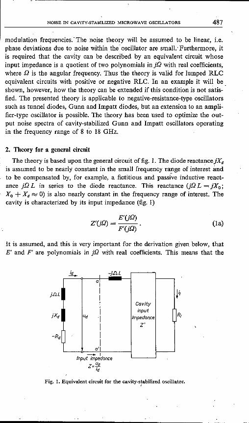
The theory is based upon the general circuit of fig. 1. The diode reactance jXd
is assumed to be nearly constant in the small frequency ra~ge of inter~st andto be compensated by, for example, a fictitious and passive inductive react-ance jQ L in series to the diode reactance. This reactance (jQ L = jXo;Xo + Xd ~ 0) is also nearly constant in the frequency range of interest. Thecavity is characterized by its input impedance (fig. 1)
E'UQ)Z'UQ)=--.
F'UQ)(la)
It is assumed, and this is very important for the derivation given below, thatE' and F' are polynomials in jQ with real coefficients. This means that the
jiu.
idI
-j.ILL-.al
11 1
1
1 Cavity
I I input [Ud 'I impedance
I z'
J II
a'l----:- I
Input Impedancez=~d
Id
Fig. 1. Equivalent circuit for the cavity-stabilized oscillator.I
488 K. SCHÜNEMANN AND B. SCHIEK
circuit is considered to be composed of lumped elements only. Then the imped-ance in the plane a-a' in fig. I is
ECD)Z(jQ) = - ·DL + Z'(jD) = _J _ .
J F(jD) , (lb)
E and F are polynomials in jD with real coefficients, too.The current iit) into the impedance Z is in general not necessarily the same
current as the load current il. These currents are related by the current trans-formation factor HU D):
N(jD). TIU'rI) . .Id= LIl ~.: II= --11.D(jD)
(2)
The .numerator and denominator of H(jD) are also polynomials in jD for thelumped case.
The current id shows amplitude and phase fluctuations L1Ad and L1 epd. In thefollowing only á linear-noise theory will be derived, i.e. L1Ad/AO' L1epd~ 1.Then id can be expressed as follows:
id(t) = Ao(t) cos [Dt + 0(0+ L1eplt)] ~ [Ao + L1Alt)] x
x [cos (Qt + 0(0)- L1 epit) sin (Dt + 0(0)] = Ao(1 + L1qJd)cos (Dt + 0(0)
= Re {Ao exp U(Dt + 0(0)] + L1qJd(t)}, (3)
where L1Ait)/Ao + L1epit)j has been abbreviated by L1qJd(t). The :fluctuationsignals L1AI(t), L1 epl(t) and L1qJl(t) of the load current
il = [AI + L1AI(t)] cos [.!~t + L1ept(t)]
are defined in a similar way. The :fluctuation signals of the load current mustnow be related to the :fluctuation signals of the diode current.
This is done by eq. (13). The derivation which leads to eq. (13) is somewhattedious and some readers may wish to skip these mathematics and to continuewith (13). The application of eq. (13) on the other hand is quite simple.
Equation (2) gives
(4)where
D = dm(jDy' + dm_1(jD)m-l + ,N = anUD)n + an_1(jD)n-l -+- .
In ac-circuit theory (jD)m is equivalent to the mth derivative dm/dtm in thetime domain. With eq. (3) and a time dependence of the Iow-frequency signalL1qJd(t) of
(5)
L1qJd(t)= t L1qJd [exp (jwt) -+- exp (-jwt)] (6)
NOISE IN CAVITY-STABILIZED MICROWAVE OSCILLATORS 489
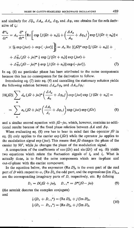
and similarly for Ll9?"LlAd' LlAI' LICf?dand LICPIone obtains for the mth deriv-ative of id:
dmi d'" { [ (LlAd)_d =Ao- Re exp[j(Dt+ao)]+ --+LlCPdj exp[j(Dt+ao)]xdt'" dt'" Ao -
X H· exp Uwt) + exp ( -jwt)] J} = Ao Re {(jD)'" exp [j (Dt + ao)] +
+ LlqJ'dUD + jw)'" t exp [j (Dt + ao)] exp Uwt) +
+ .tfepd(jD- jw)'" t exp [j (Dt + ao)] exp (-jwt)}. (7)
In eq. (6) no particular phase has been attributed to the noise componentsbecause this has no consequence for the derivation to follow.Introducing eq. (7) into eq. (4) and cancelling the stationary solution yields
the following relation between LlAd,LICPdand LlA"LI CPI:
IHUD)II d", (jD + jw)'" ( ~d + LlCPdj) exp Uwt) exp [j (Dt + ao)] =
In
= I an UD +jw)n (LI;I + LlCPI~)exp Uwt) exp UDt) (8)
n
and a similar second equation with jD-jw, which, however, contains no addi-tional results because of the fixed phase relation between LlA and LIcp.When evaluating eq. (8) one has to bear in mind that the operator jD in
eq. (8) only applies to the carrier exp (jDt) while the operator jto applies tothe modulation signal exp Uwt). This means that jD changes the phase of thecarrier by 90°, while jto changes the phase of the modulation signal.
A comparison of the coefficients of cos (Dt) and sin (Dt) of eq. (8) yieldstwo equations which relate the fluctuation signals of id and ilo What isactually done, is to find the noise components which are in-phase andout-of-phase with the carrier component.In the equation below, the expression (Re D)e is the even part of the real
part of D with respect to co, (Re D)o the odd part, and the expressions (lm D)e.oare the corresponding imaginary parts of D, respectively, etc. By defining
Dl = DUD +jw), D_l* = D*(jQ- jw)
(the asterisk denotes the complex conjugate)and
(9)
t (Dl + D_l*) = (Re D)e + j(lm D)o,
t (Dl - D_l*) = (Re D)o +j (Im D)e(10)
\
490 K. SCHONEMANN AND B. SCHIEK
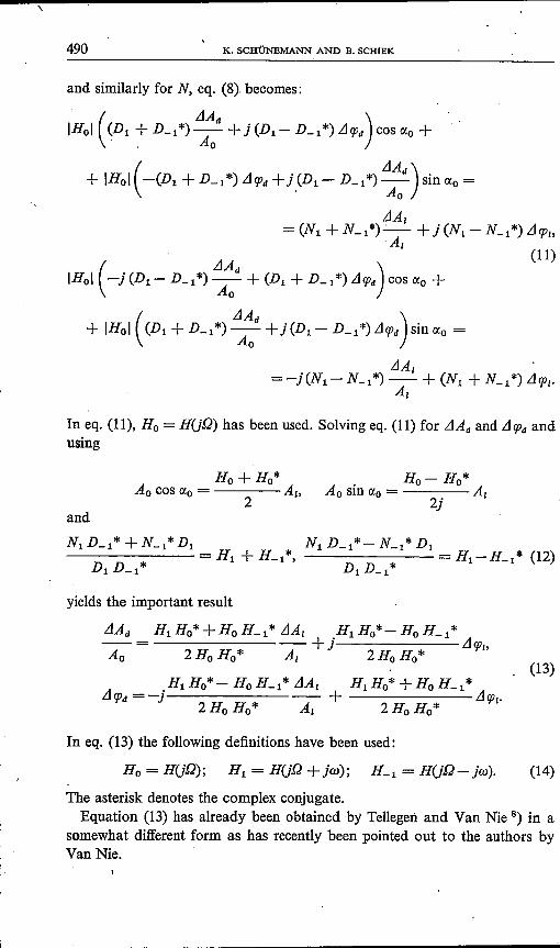
and similarly for N, eq. (8). becomes:
('LIA )IHol (Dl +D_l*) Aod +j(Dl-D_l*)Llq;d cos «, +
+ IHol (-(Dl + D_l*) Llq;d+ j,(Dl - D_l*) LlA~d) sin £Xo=
(LlAd )IHol -j(Dl-D_l*) Ao +(Dl+D_l*)Llq;d cos£xo+
+ IHol (Dl + D_l*) :~d + j (Dl - D_l*) Llq;d) sin £Xo=
In eq. (11), Ho = H(jQ) has been used. Solving eq. (11) for LlAd and Llq;dandusing
Ho- Ho*Ao sin £Xo= A,2j
and
Nl o:» + s:» Dl n,D_l*- u:» Dl------- = Hl + H_l*, . = Hl-H_l* (12)
Dl D_l* Dl D_l* .
yields the important result
. (13)
In eq. (I3) the following definitions have been used:
Ho = H(jQ); Hl = H(jQ +jw); H-l = H(jQ- jw). (14)
The asterisk denotes the complex conjugate.Equation (13) has already been obtained by Tellegen and Van Nie 8) in a
somewhat different form as has recently been pointed out to the authors byVan Nie.
NOISE IN CAVITY-STABILIZED MICROWAVE OSCILLATORS 491
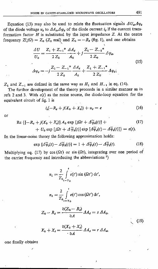
Equation (13) mayalso be used to relate the fluctuation signals L1Ud,L11pd
of the diode voltage Udto LlAd,LIC{Jd of the diode current id if the current trans-formation factor H is substituted by the input impedance Z. At the centrefrequency ZUD) = Zo (Zo real) and Zo = -Rd (fig. I), and one obtains
'-
LlU
(15)
Z, and Z-1 are defined in the same way as HI and H_1 in eq.. (14).The further development of the theory proceeds in a similar manner as in
refs 2 and 3. With eet) as the noise source, the diode-loop equation for theequivalent circuit of fig. I is
(16)
or
Re {[-Rd +j(Xo +Xd)] Ao exp U.Qt + Llq;it)] + (17)
+ Uo exp UDt + LIqîit)] exp [Ll1Pd(t)- Llqîit)]} = eet).
In the linear-noise theory the following approximation holds:
exp [LI:;Plt)- Llqîit)] = 1+ LI:;Plt)- Llqîd(t). (18)
Multiplying eq. (17) by cos (.Qt) or sin (.Qt), integrating over one period ofthe carrier frequency and introducing the abbreviations 2)
2 '.n1 = - f eet') sin (.Qt') dt',
Tot-To
2 t
n2 = - f eet') cos (Dt') dt',To
t-To
" (19)
one finally obtainsI
492 K. SCHONEMANN AND B. SCHIEK
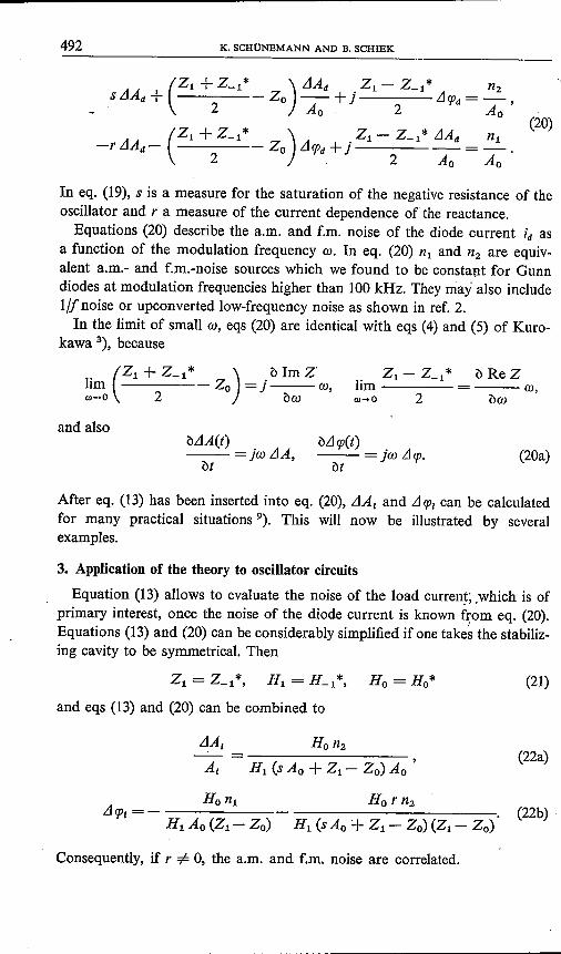
(20)
In eq. (19), s is a measure for the saturation of the negative resistance of theoscillator and r a measure of the current dependence of the reactance.Equations (20) describe the a.m. and f.m. noise of the diode current id as
a function of the modulation frequency (I). In eq. (20) n1 and n2 are equiv-alent a.m.- and f.m.-noise sources which we found to be constant for Gunndiodes at modulation frequencies higher than 100 kHz. They mayalso includel/Jnoise or upconverted Iow-frequency noise as shown in ref. 2.In the limit of small (I), eqs (20) are identical with eqs (4) and (5) of Kuro-
kawa 3), because
)b Im Z
Zo = j --- (I),bw
Zl-Z_1* e ne zlim = --- (I),w-+o 2 öco
and alsobLlA(t)--=jwLlA,
btM<p(t)--=jwLl<p.
bt(20a)
After eq. (13) has been inserted into eq. (20), LlA, and LI<P, can be calculatedfor many practical situations 9). This will now be illustrated by severalexamples.
3. Application of the theory to oscillator circuits
Equation (13) allows to evaluate the noise of the load current; .which is ofprimary interest, once the noise of the diode current is known from eq. (20).Equations (13) and (20) can be considerably simplified if one takes the stabiliz-ing cavity to be symmetrical. Then
(21)
and eqs (13) and (20) can be combined to
LlA, Ho n2--= ,A, Hl (s Ao + Z, - Zo) Ao
(22a)
Consequently, if r =1= 0, the a.m. and f.m. noise are correlated.
NOISE IN CAVITY-STABILIZED MICROWAVE OSCILLATORS~----- 493
3.1. A comparison between transmission- and reaction-cavity-stabilized oscillators
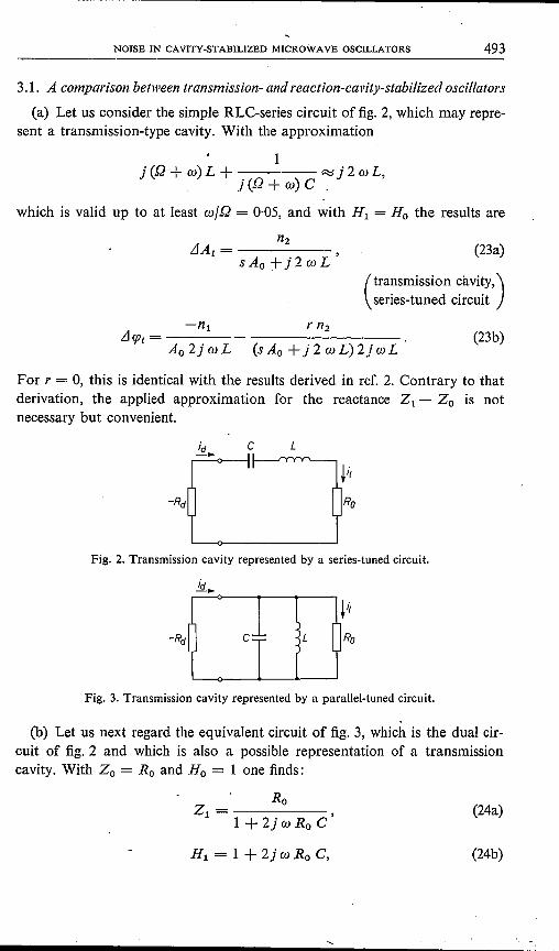
Ca) Let us consider the simple RLC-series circuit of fig. 2, which may repre-sent a transmission-type cavity. With the approximation
1j ([2 + w) L + ~ j 2 o: L,
j ([2 + w) C .
which is valid up to at least wlQ = 0,05, and with Hl = Ho the results are
n2LlAI = ------
s Ao + j 2 wL(23a)
(transmission cavity,)series-tuned circuit
-nl r n2LlqJl =----
Ao2jwL (sAo+j2wL)2jwL(23b)
For r = 0, this is identical with the results derived in ref. 2. Contrary to thatderivation, the applied approximation for the reactance Z, - Zo is notnecessary but convenient.
c L
Fig. 2. Transmission cavity represented by a series-tuned circuit.
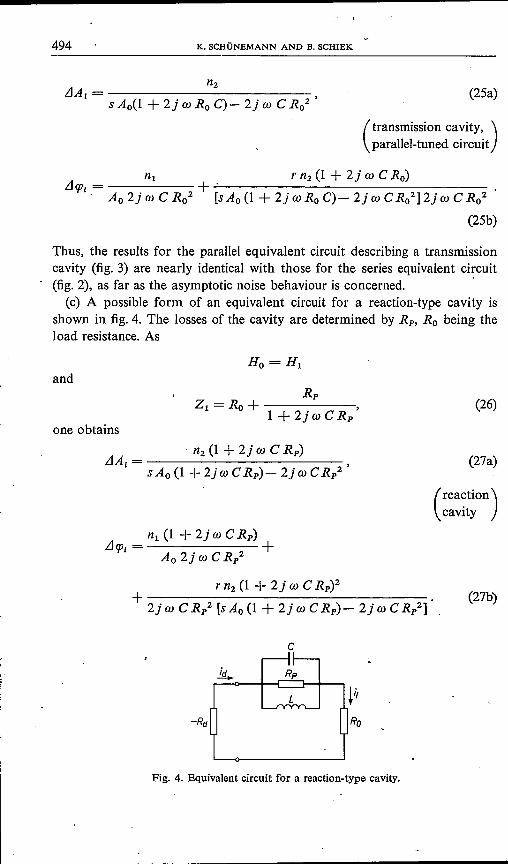
c
Fig. 3. Transmission cavity represented by a parallel-tuned circuit.
(b) Let us next regard the equivalent circuit of fig. 3, which is the dual cir-cuit of fig. 2 and which is also a possible representation of a transmissioncavity. With Zo = Ro and Ho = lone finds:
RoZl = ,
1+ 2j t» Ro C(24a)
Hl = 1 + 2jwRo C, (24b)
494 K. SCHONEMANN AND B. SCHIEK
n2jA,= ,
s Ao(l + 2j w Ro C)- 2j co C Ro2(25a)
(transmission cavity, )parallel-tuned circuit
n1 r n2 (1 + 2j w C Ro)jtp, = + ..;_' _. Ao 2j wC Ro2 [s Ao (1 + 2j w s, C)- 2j wC Ro2] 2j wC Ro2
(25b)
Thus, the results for the parallel equivalent circuit describing a transmissioncavity (fig. 3) are nearly identical with those for the series equivalent circuit(fig. 2), as far as the asymptotic noise behaviour is concerned. .(c) A possible form of an equivalent circuit for a reaction-type cavity is
shown in fig. 4. The losses of the cavity are determined by Rp, Ro being theload resistance. As
andRp
Z1 = Ro + ------1 +2jwCR/
(26)
one obtains
(27a)
(rea~tion)cavity
Ra
Fig. 4. Equivalent circuit for a reaction-type cavity.
NOISE IN CAVITY-STABILIZED MICROWAVE OSCILLATORS 495
For a comparison the noise spectra for the transmission cavity will be de-noted by LIAr and LIcp" those of the reaction cavity by LIAr and LIcp" respectively.
Considerable effort has been devoted to the problem of measuring rand s; however, withno success. In one of the methods used, a frequency-modulated locking signal is applied tothe oscillator under investigation. The locked oscillator will not convert the f.m. modulationinto a.m, modulation if r = 0 and if the free-running frequency of the locked oscillatoris coincident with the locking-signal frequency. Additionally if r =F 0, a new locking-signalfrequency may be found which makes the converted a.m. modulation a minimum: thisfrequency deviation is a measure of ris. Unfortunately, a fraction of the locking signal isreflected from the oscillator to be measured. This reflected signal adds to the locked oscillatorsignal and mayalso produce an a.m. modulation 18) which is ofthe same order of magnitude.Therefore the detection of the a.m, minimum becomes quite uncertain. The same limitationhas been obtained with other methods. The a.m. and f.m, noise correlations have also beenmeasured directly and were found to be fairly small but quite dependent on the tuning of theoscillator.
Since the a.m.-f.m.-conversion terms, which contain r, have only a negligibleinfluence upon the asymptotic noise behaviour, these terms have been omittedin the following discussion.A comparison of eqs (23) and (27) shows that the noise spectra differ con-
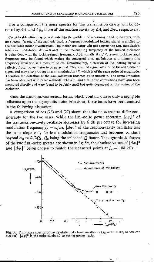
siderably for the two cases. While the f.m.-noise power spectrum ILlcp,I2 ofthe transmission-cavity oscillator decreases by 6 dB per octave for increasingmodulation frequency fm = wJ2n, ILlCPrl2 of the reaction-cavity oscillator hasthe same slope only for low modulation frequencies and becomes constantbeyond Wo = QJ2Qo, Qo being the unloaded Q factor. The asymptotic shapesof the two f.m.-noise spectra are shown in fig. 5a, the absolute values of ILl cp, 12
and ILlCPrl2 being chosen to match the measured points at fm = 100 kHz.
c 0 Measurements
:::::,: Asymptotes of the theory
i -110
-720
cavity
-730
0·7 0·2 0·5 2 5 70- fm(MHz)
Fig. 5a. F.m.-noise spectra of cavity-stabilized Gunn oscillators (Jo = 16 GHz, bandwidth500 Hz). ILltpl2 is the noise-sideband to carrier-power ratio.
,496 K. SCHONEMANN AND B. SCHIEK
-·IJO
o 0 Measurements:-:-::-::::Asymptotes of the theory
-115
(~A /(dB)
o t -120
-12Sb-_-o-_-o-_--o_.,....,~
Reaction cavity
/ Transmission cavity--o----o----o-----~
"-IJS
0·1 0·2 0·5 2 5 la- fm (MHz)
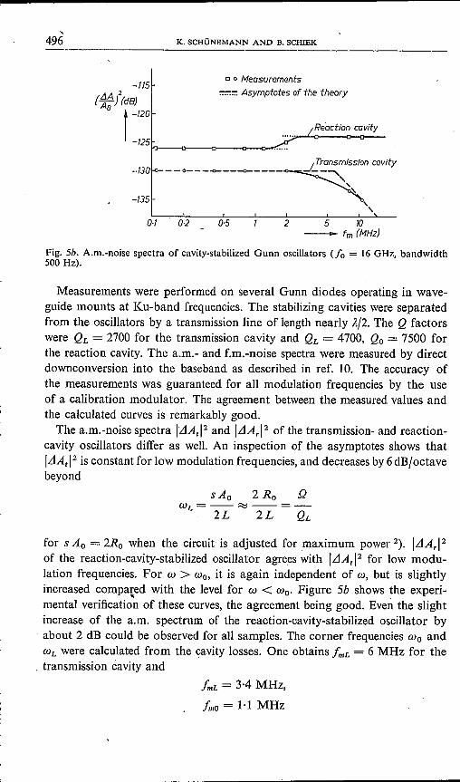
Fig. Sb. A.m.-noise spectra of cavity-stabilized Gunn oscillators (fa = 16 GHz, bandwidth500 Hz).
Measurements were performed on several Gunn diodes operating in wave-guide mounts at Ku-band frequencies. The stabilizing cavities were separatedfrom the oscillators by a transmission line of length nearly A/2. The Q factorswere QL = 2700 for the transmission cavity and QL = 4700, Qa = 7500 forthe reaction cavity. The a.m.- and f.m.-noise spectra were measured by directdownconversion into the baseband as described in ref. 10. The accuracy ofthe measurements was guaranteed for all modulation frequencies by the useof a calibration modulator. The agreement between the measured values andthe calculated curves is remarkably good.The a.m.-noise spectra ILlAtl2 and ILlArl2 of the transmission- and reaction-
cavity oscillators differ as well. An inspection of the asymptotes shows thatILlAtl2 is constant for low modulation frequencies, and decreases by 6dB/octavebeyond
sAa 2 n; QWL=--~--=-
2L 2L QL
for s Aa = 2Ro when the circuit is adjusted for maximum power 2). ILlArl2of the reaction-cavity-stabilized oscillator agrees with ILlAtl2 for low modu-lation frequencies. For W > Wo, it is again independent of w, but is slightlyincreased compared with the level for W < Wo. Figure 5b shows the experi-. .mental verification of these curves, the agreement being good. Even the slightincrease of the a.m. spectrum of the reaction-cavity-stabilized oscillator byabout 2 dB could be observed for all samples. The corner frequencies Wo andWL were calculated from the 9avity losses. One obtains fmL = 6 MHz for the
. transmission cavity andfmL = 3·4 MHz,
Irno = 1·1 MHz
NOISE IN CAVITY-STABILIZED MICROWAVE OSCILLATORS '497
for the reaction cavity. The differences between the measured and calculatedvalues are small.Concluding this comparison, some hints will be given concerning the choice
between the two cavities. The transmission-type cavity should be preferred, ifthe noise spectrum for W > Wo is of interest. In many applications, however,this is not the case. Then the shapes of the noise spectra are not a criterionfor choosing one or the other cavity. Further, the two types of cavities showequal power losses for equal noise-reduction factors 11). The transmissioncavity gives rise to unwanted modes of oscillation 4). To suppress these modes,a damping resistance must be inserted between the oscillator and the cavity,but this involves a more complicated network and power losses typically ofI dB. The damping resistance is not necessary for the reaction cavity if the loadresistance is well matched over a large frequency range.
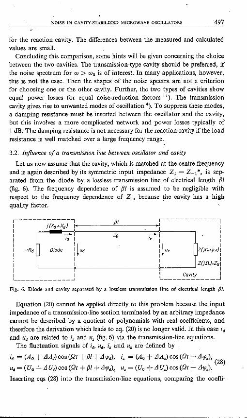
3.2. Influence of a transmission line between oscillator and cavity
Let us now assume that the cavity, which is matched at the centre frequencyand is again described by its symmetric input impedance Z1= Z-l *, is sep-arated from the diode by a lossless transmission line of electrical length f31(fig. 6). The frequency dependence of f31 is assumed to be negligible withrespect to the frequency dependence of Zl' because the cavity has a highquality factor.
1-----------,IIIIII -RdIIIIIL __J
j (XO+!d) 1 - 1
~i Zo ~IIz I
~Diode It Ud : t Uz ]
II 1IT
/11 r-----------lIIIII
Z(j.Il+jCJ) II
. IZ(j.Il.)=Zol
II Cavity IL _J
Fig. 6. Diode and cavity separated by a lossless transmission line of electrical length f31.
Equation (20) cannot be applied directly to this problem because the inputimpedance of a transmission-line section terminated by an arbitrary impedancecannot be described by a quotient of polynomials with real coefficients, andtherefore the derivation which leads to eq. (20) is no longer valid. In this case idand Ud are related to t, and Uz (fig. 6) via the transmission-line equations.The fluctuation signals of id, Ud' iz and Uz are defined by
id = (Ao + LlAd) cos (Dt + f31+ LICPd), iz = (Ao + LlAz) cos (Dt + LIcpz),(28)
Ud= (Uo + LIUd) cos (Dt + f31+ Ll7jJd)~ v,= (Uo + LIUz) cos (Dt + Ll7jJz).
Inserting eqs (28) into the transmission-line equations, comparing the coeffi-

498------------------------------------.---------------K. SCHÜNEMANN AND B. SCHIEK
cients of the cos (Dt) and sin (Dt) terms and using eq. (15) yields linear equa-.tions which relate the fluctuation signals to each other:
LlAd = (Z1 + ZoAo 2Zo
Z1 .; Zo ) LlAz z, - Zo--- cos (2fJ!) - - sin (2fJ!) LIrpz,
2 Zo Ao 2Zo'
z, - Zo LlAz (Zl + Zo Z1 - Zo )LIrpd= sin (2fJ!) - + - cos (2fJ!) LIrpz,
2 Zo Ao 2 Zo 2 Zo
(29)LlUd (Z1 + Zo z, - Zo ) LlAz z, - Zo .- = + cos (2fJ!) - + sin (2fJ!) LIrpz,U 0 2 Zo 2 Zo Ao 2 Zo
Z1 - Zo LlAz (Zl + Zo Z1 - Zo )Ll1pd= - sin (2fJ!) - + + cos (2fJ!) LIrpz.
2 Zo s; 2 Zo 2 Zo
The evaluation of the diode-loop equation yields
(30a)
(30b)
Substituting LlAd' LIUd, LIrpd and Ll1pd by eq. (29), one obtains two linearequations which can be solved for LlAz and LIrpz:
[ ( rAo ) (SAo) ] 1LlAz = n2 - sin (2fJ!) - cos (2fJ!) + n1 - - 1 sin (2fJ!) -,2~ 2~ D~
(31a)
, {[( sAo ) sAo Z1 + Zo]Llrpz = n1 1- - cos (2fJ!) +- +2Zo 2Zo Z1 - Zo
(3Ib)
[r Ao (Z1 + Zo ) ]} 1+ n2 - - cos (2fJ!) - sin (2fJ!) ---,2 Zo Zl,- Zo Ao Det
(SAo) Z1 + ZoDet = -(Z1 - Zo) 1- - - [s Ao cos (2fJ!) - r Ao sin (2fJ!)].2Zo 2Zo1
. ' (3Ic)A considerable simplification of these equations is possible for the condition
NOISE IN CAVITY-STABILIZED MICROWAVE OSCILLATORS 499
of maximum output power 2):
sAo-=1.2Z0
(32)
Then
n1 cos e + n2 sin e- [(ZI - ZO)/(ZI + Zo)] sin (2(3/+ e) n2Ltcpz = , (33b)
-(Z1 - Zo) cos (2(3/+ e) Ao
where a diode angle e has been defined as 3)
s = k cos e,r = k sin e. (34)
A simplification is also possible if one considers only low modulation frequen-cies, i.e. ZI - Zo «ZI + Zo R:i 2Zo, because lim Z1 = Zo. Then
0)-+0
n2 ( s Ao) n2 cos (2(3/)+ n1 sin (2(3/)LtAz = -- + 1- -- ,
2 Zo 2 Zo k Ao cos (2(31+ e)(35a)
nl cos e + n2 sin eLt qJz =• .
-(Z1 - Zo) cos (2(31+ e) Ao(35b)
Consequently, for both approximations, the a.m. noise is nearly independentof the line length (31,while the f.m. noise power, varies essentially proportionalto cos=" (2(31+ e). For low modulation frequencies this result is shown tobe valid for a quite general circuit (see sec. 3.3).In most .practical cases the oscillator will be tuned for maximum output
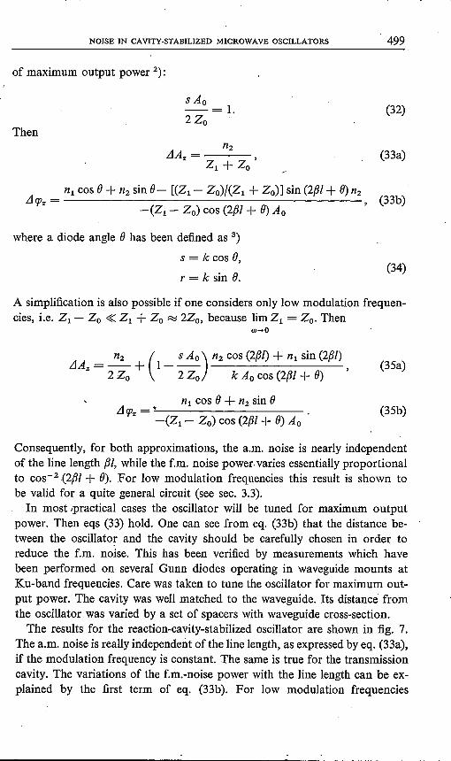
power. Then eqs (33) hold. One can see from eq. (33b) that the distance be-tween the oscillator and the cavity should be carefully chosen in order toreduce the f.m. noise. This has been verified by measurements which havebeen performed on several Gunn diodes operating in waveguide mounts atKu-band frequencies. Care was taken to tune the oscillator for maximum out-put power. The cavity was well matched to the waveguide. Its distance' fromthe oscillator was varied by a set of spacers with waveguide cross-section.The results for the reaction-cavity-stabilized oscillator are shown in fig. 7.
The a.m. noise is really independent ofthe line length, as expressed byeq. (33a),if the modulation frequency is constant. The same is true for the transmissioncavity. The variations of the f.m.-noise power with the line length can be ex-plained by the first term of eq. (33b). For low modulation frequencies
500 K. SCHONEMANN AND B. SCHIEK
I
o F.m.measurement I
-76 I
/~~l(dB,'1.ó.'PrI2(dB) o A.m. measurement ?
1-80 -128
1-840 0 0
-126
-124
-92
-96
-1001 3 5 9 11 13
_I (mm)
1f 1f 31f 21f 51f"2 2"
-2fJI+B2"
Fig. 7. A.m. and f.m. noise of a reaction-cavity-stabilized Gunn oscillator versus the distanceof the cavity from the oscillator (Pout = 150 mW, fo = 16 GHz, at 100 kHz from the car-rier in 500-Hz bandwidth, f.m, noise of the free-running oscillator ILlrpl2 = -65 dB).
(/,,,= w/2n = 100 kHz for the curves of fig. 7), the second term of eq. (33b),which accounts for an a.m. conversion, can be neglected compared with thefirst term. Its influence will be discussed later. Once again it can be seen fromfig. 7 that the distance between the oscillator and the cavity must be carefullyadjusted in order to take full advantage of the stabilizing effect of the cavity.It is a striking result of the measurements that highly stabilized oscillations
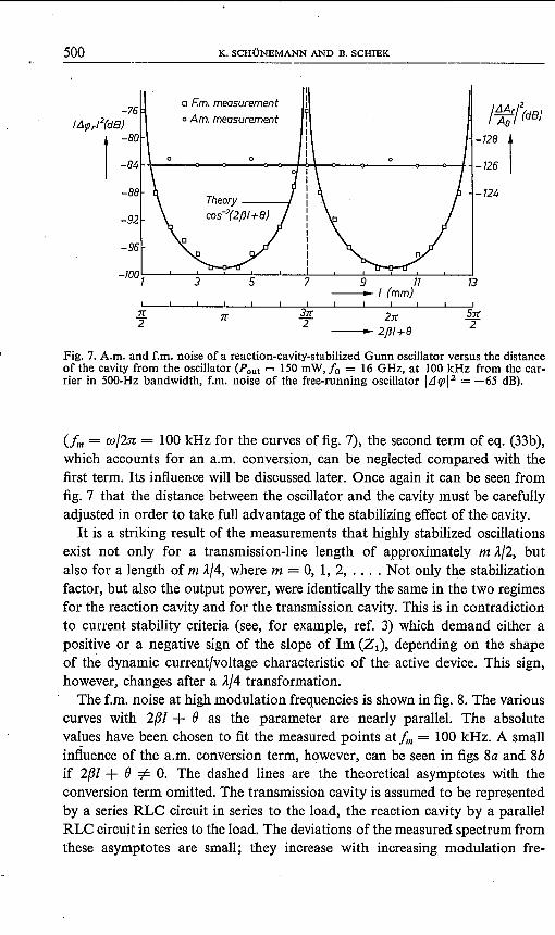
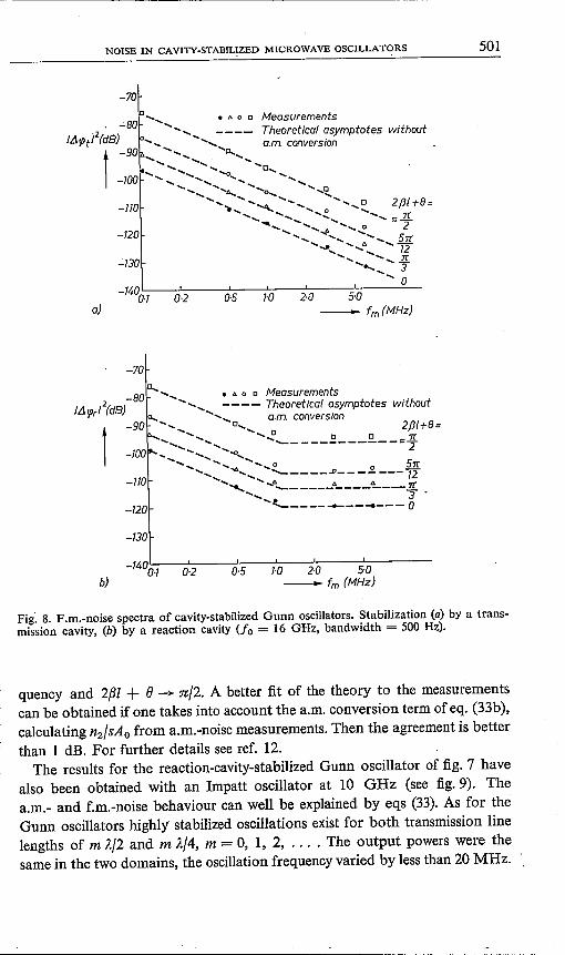
exist not only for a transmission-line length of approximately m A/2, butalso for a length of m J..f4, where m = 0, 1, 2, .... Not only the stabilizationfactor, but also the output power, were identically the same in the two regimesfor the reaction cavity and for the transmission cavity. This is in contradictionto current stability criteria (see, for example, ref. 3) which demand either apositive or a negative sign of the slope of lm (Z1), depending on the shapeof the dynamic current/voltage characteristic of the active device. This sign,however, changes after a J..f4 transformation.The f.m. noise at high modulation frequencies is shown in fig. 8. The various
curves with 2(Jl + ()as the parameter are nearly parallel. The absolutevalues have been chosen to fit the measured points at!", = 100 kHz. A smallinfluence of the a.m. conversion term, however, can be seen in figs 8a and 8bif 2(Jl + ()=1= O. The dashed lines are the theoretical asymptotes with theconversion term omitted. The transmission cavity is assumed to be representedby a series RLC circuit in series to the load, the reaction cavity by a parallelRLC circuit in series to the load. The deviations of the measured spectrum fromthese asymptotes are small; they increase with increasing modulation fre-
NOISE IN CAVITY-STABILIZED MICROWAVE OSCILLATORS. - 501
-70
......... ..... .................. ..... .....
<, ....'0........................ ..... .....
.............. .....0-100 .....................................0........ ..... ...........
<, ...............A.". <, 0 ...............[J
........... ............... ..... ............. ....."'-4,......... ... .....0 2fJI+8=................. ~..... ......<, :::::JL
"" IJ. <, ~ 2....................... A........... Srr.................... .....72
..... ........... 1T..........................3
.....0-140L---'----'-----'----'----'---:::__
0·1 0·2 0·5
• IJ. 0 0 MeasurementsTheoretical asymptotes withouta.m. conversion
-110
-120
.;.130
I-a 2·0 5·0_ fm(MHz}a}
-70
• '" 0 0 MeasurementsD..._ .....-80 ...
IL!ljIr/2(dB} ....................---- Theoretica! asymptotes without-90 <>............. <, a.m. conversion
<, 0....... 2fJI+8=............... .....~ 0 0 1(...................."""------------=2
-100.... ..................-.0..........................<,...0. 0 0 5n
........... ........_----~------- 12.............. .....A........ tJ. ~ 1(
............... 3--------- ....--- 0
t-110
-120
-130
0-2 0·5 1-0 2·0 5-0-fm (MHz)b}
Fig~ 8. F.m.-noise spectra of cavity-stabilized Gunn oscillators. Stabilization (a) by a trans-mission cavity, (b) by a reaction cavity (Jo = 16 GHz, bandwidth = 500 Hz).
quency and 2{31+ e -)0 n/2. A better fit of the theory to the measurementscan be obtained if one takes into account the a.m. conversion term of eq. (33b),calculating nz/sAo from a.m.-noise measurements. Then the agreement is betterthan 1 dB. For further details see ref. 12.The results for the reaction-cavity-stabilized Gunn oscillator of fig. 7 have
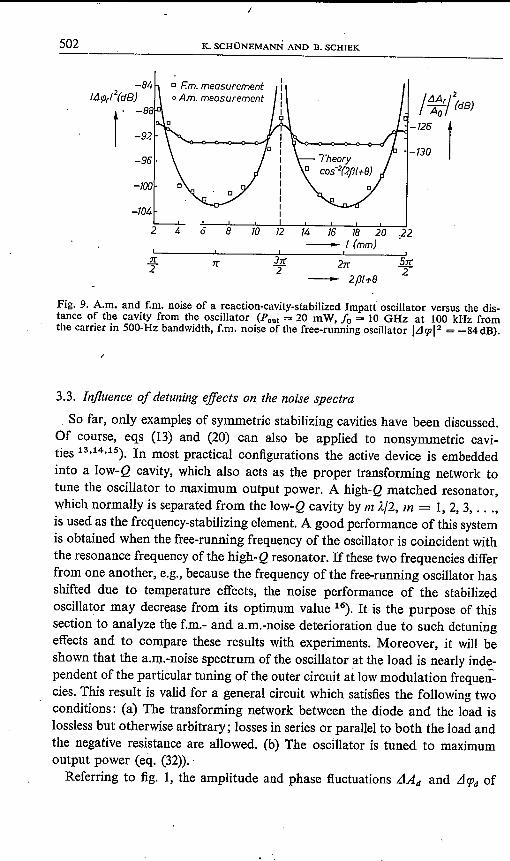
also been obtained with an Impatt oscillator at 10 GHz (see fig.9). Thea.m.- and f.m.-noise behaviour can well be explained by eqs (33). As for theGunn oscillators highly stabilized oscillations exist for both transmission linelengths of m J..f2 and m Af4, m = 0, 1, 2, .... The output powers were thesame in the two domains, the oscillation frequency varied by less than 20 MHz.
502 K. SCHONEMANN AND B. SCHIEK
o F.m.measuremento A.m. measurement /~~{(dB)
-130 1r-96
-100
-104
2 4 Ö 8 10 12 14 16 18 20 ,22-[(mm)
:n:2'
3:n:T 2:n:
- 2fl[+8
5:n:""2
Fig. 9. A.m. and f.m. noise of a reaction-cavity-stabilized Impatt oscillator versus the dis-tance of the cavity from the oscillator (Pout = 20 mW, fa = 10 GHz at 100 kHz fromthe carrier in 500-Hz bandwidth, f.m. noise of the free-running oscillator ILl9112 = -84 dB).
3.3. Influence of detuning effects on the noise spectra
So far, only examples of symmetric stabilizing cavities have been discussed.Of course, eqs (13) and (20) can also be applied to nonsymmetrie cavi-ties 13.14.15). In most practical configurations the active device is embeddedinto a low-Q cavity, which also acts as the proper transforming network totune the oscillator to maximum output power. A high-Q matched resonator,which normally is separated from the low-Q cavity by m A.f2, m = 1,2,3, ... ,is used as the frequency-stabilizing element. A good performance of this systemis obtained when the free-running frequency of the oscillator is coincident withthe resonance frequency ofthe high-Q resonator. Ifthese two frequencies differfrom one another, e.g., because the frequency ofthe free-running oscillator hasshifted due to temperature effects, the noise performance of the stabilizedoscillator may decrease from its optimum value 16). It is the purpose of thissection to analyze the f.m.- and a.m.-noise deterioration due to such detuningeffects and to compare these results with experiments. Moreover, it will beshown that the a.m.-noise spectrum of the oscillator at the load is nearly ind~-pendent of the particular tuning of the outer circuit at lowmodulation frequen-cies. This result is valid for a general circuit which satisfies the following twoconditions: (a) The transforming network between the diode and the load islossless but otherwise arbitrary; losses in series or parallel to both the load andthe negative resistance are allowed. (b) The oscillator is tuned to maximumoutput power (eq. (32)).Referring to fig. 1, the amplitude and phase fluctuations .dAd and LllPd of
NOISE IN CAV~TY-STABILIZED MICROWAVE OSCILLATORS 503
the diode current may be calculated for low modulation frequencies from eqs(20) and (20a):
()Im(Z) jw LlAd () Re(Z) nzs LlAd + -- + jw Llepd= -, (36a)
. öco Ao ()w . Ao
ö Re(Z)jw LlAd ö Im(Z) nl '-rLlAd+ --- jWLlepd=-' (36b)
()w Ao ()w Ao
Furthermore, for small modulation frequencies, the second terms in eqs (36)can be neglected with respect to the first.The noise fluctuations LlAI and LIepi of the load current are related to the
noise of the diode current via the current transformation factor H = id/i"which in this case includes the low- and the high-Q cavity. In addition, forsmall modulation frequencies, the small a.m.-f.m.-conversion term can beneglected in eqs (13). Equation (13) then reads: .
LlAd LlAI ()(H H*) 1-- = -- + jw LIep"Ao AI ()w 2H H*
LllPd = LIep" lim w -+ O.
In eqs (37) use has been made of
(37a)
(37b)
Inserting eqs (37) into eqs (36) yields
Ao(39a)
nl cos 0 + nz sin 0Llepl = --------
jco I()Z/()wlsin (0 - y)'(39b)
where an angle y has been introduced by
e Re(Z) ()Im(Z) 'I ()Z I___ +j = -- (cosy +jsiny).()w ()w ()w
(40)
The relationfor LIep,has already been derived in ref. 17, although the effectof a transforming network between the diode and the load has not been taken
504 K. SCHÜNEMANN AND B. SCHIEK
into account. Hence the expression for the f.m. noise in ref. 17 is only validfor the diode current. Fortunately eq. (37b) is valid so that the theoretical'discussion of the measured f.m. noise in ref. 17 is justified. This is not thecase, however, for the a.m. noise of the load current, which must be calculatedfrom eq. (39a). This expression reduces considerably under the above-citedconditions (a) and (b). While (b) leads to eq. (32), (a) has the consequence
Re(Z) il = R, i,2 or Re(Z) H H* = R,
(R, is the load resistance) or(41a)
(l Re(Z) (l(H H*) 1---+Zo --=0.
(lcv (lCV H H* (41b)
The expression in the rectangle of eq. (39a) vanishes when the relations ofeqs (32) and (4Ib) are introduced. Then the a.m. noise is simply given by
--=---- (42)
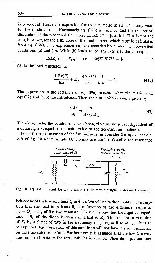
Therefore, under the conditions cited above, the a.m. noise is independent ofa detuning and equal to the noise value of the free-running oscillator.For a further discussion of the f.m. noise let us consider the equivalent cir-
cuit of fig. 10 where simple Le circuits are used to describe the resonance
Low-Q-cavityresonance at .a,
Stabilizing-cavityresonance at .fl2
~
>"/2
Fig. 10. Equivalent circuit for a two-cavity oscillator with simple Le-resonant elements.
behaviour ofthe low- and high-Q cavities. We willmake the simplifying assump-tion that the load impedance R, is a function of the difference frequencyCV,d = £21 - D2 of the two resonators' in such a way that the negative imped-ance -Rd of the diode is always matched to Zo.This requires a variationof R, by a factor of two in the frequency range CV,d = 0 to CV,d max- It is tobe expected that a violation of this condition will not have a strong influenceon the f.m.-noise behaviour. Furthermore it is assumed that the low-Q cavitydoes not contribute to the total stabilization factor. Then its impedance can
NOISE IN CAVITY-STABILIZED MICROWAVE OSCILLATORS 505
be abbreviated by jXo. For a slight to moderate detuning of the high-Q cavitythe input impedance of the outer circuit is
RIZ=jXo + .
1+ 2j(OJA + OJ)RI Cz
Matching the diode to the load, eqs (43) and (39b) yield for the f.m. noise:
(43)
nlL1tpl = ------------
2j OJZoz c. [1- (OJA/OJA max)Z] Aa
In eq. (44), ()= 0 has been assumed for simplicity, OJA rnax = ± (2 RI Cz)-lis the maximum frequency deviation in the pulling range for the equivalentcircuit of fig. 10. The a.m. noise is given by eq. (42), because the conditions (a)and (b) are satisfied.Of course, the equivalent circuit of fig. 10 is only an approximation to an
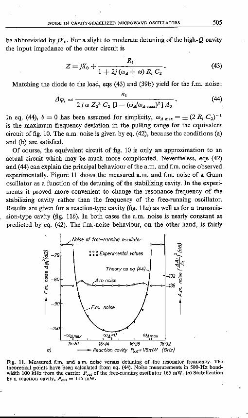
actual circuit which may be much more complicated. Nevertheless, eqs (42)and (44) can explain the principal behaviour ofthe a.m. and f.m. noise observedexperimentally. Figure 11 shows the measured a.m. and f.m. noise of a Gunnoscillator as a function of the detuning of the stabilizing cavity. In the experi-ments it proved more convenient to change the resonance frequency of thestabilizing cavity rather than the frequency of the free-running oscillator.Results are given for a reaction-type cavity (fig. l Izz)as well as for a transmis-sion-type cavity (fig. lIb). In both cases the a.m. noise is nearly constant aspredicted by eq. (42). The f.m.-noise behaviour, on the other hand, is fairly
~ -70~"'-s.'0::]ClJ.~g-80 ,~È 0----0 ' 0---<>
L(
t -90
-100
(44)
Noise of free-running oscillatoräJ~
:?I'-'0::]<;(..._-132 .~
oc::-136
È<;i
t
~~~ Experimental values
W.dmax
16-20 16·24 16·28 16·32a} - Reaction cavity Pout=115mW (GHz)
Fig. 11. Measured f.m, and a.m, noise versus detuning of the resonator frequency. Thetheoretical points have been calculated from eq. (44). Noise measurements in 500-Hz band-width 100 kHz from the carrier. Pout of the free-running oscillator 165mW. (a) Stabilizationby a reaction cavity, Pout = 115 mW.
506 K. SCHONEMANN AND B. SCHIEK
~~~ Experimental values
Ql~ -80~ A.m. noise"<:J -84QJ.~g -88
No synchronization
ëi)~~-I-"<:J"'l:..._
QJ
-132 .~c:
-136 e;"'l:
1
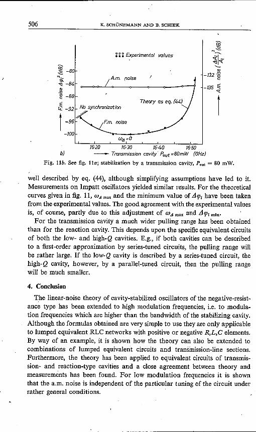
16·20 16·30 16·40 16·50b) - Transmission covtty Pout =80mW (GHz)
Fig. llb. See fig. lla; stabiJization by a transmission cavity, Pout = 80 mW.
well described by eq. (44), although simplifying assumptions have led to it.Messurements on lmpatt oscillators yielded similar results. For the theoreticalcurves given in fig. 11, Wil malt and the minimum value of AlP, have been takenfrom the experimental values. The good agreement with the experimental valuesis, of course, partly due to this adjustment of Wil malt and AlP, min'
For the transmission cavity a much wider pulling range has been obtainedthan for the reaction cavity. This depends upon the specificequivalent circuitsof both the low- and high-Q cavities. E.g., if both cavities can be describedto a first-order approximation by series-tuned circuits, the pulling range willbe rather large. If the low-Q cavity is described by a series-tuned circuit, thehigh-Q cavity, however, by a parallel-tuned circuit, then the pulling rangewill be much smaller.
4. Conclusion
The linear-noise theory of cavity-stabilized oscillators of the negative-resist-ance type has been extended to high modulation frequencies, i.e. to modula-tion frequencies which are higher than the bandwidth of the stabilizing cavity.Although the formulas obtained are very simple to use they are only applicableto lumped equivalent RLC networks with positive or negative R,L,C elements.By way of an example, it is shown how the theory can also be extended tocombinations of lumped equivalent circuits and transmission-line sections.Furthermore, the theory has been applied to equivalent circuits of transmis-sion- and reaction-type cavities and a close agreement between theory andmeasurements has been found. For low modulation frequencies it is shownthat the a.m. noise is independent of the particular tuning of the circuit underrather general conditions.
/ ,
NOISE IN CAVITY-STABILIZED MICROWAVE OSCILLATORS 507
Acknowledgement
The authors wish to thank J. K. Vogel from Valvo GmbH Hamburg,W. Schilz and H. J. Schmitt from Philips Forschungslaboratorium HamburgGmbH, M. T. Vlaardingerbroek from Philips Research Laboratories Eindho-ven, and J. Magarshack from L.E.P. Paris for valuable discussions. Acknowl-edgement is made to J. Köhler from Philips Forschungslaboratorium HamburgGmbH for his aid in carrying out the measurements. We are indebted to Prof.Dr W. Harth from the Institut für Hochfrequenztechnik der Technischen I
Universität Braunschweig, who supplied the Impatt diodes.
Philips Forschungslaboratorium Hamburg, June 1972
REFERENCES1) W. A. Edson, Proc. IRE 48, 1454-1466, 1960.2) K. Kurokawa, IEEE Trans. M'IT-l6, 234-240, 1968.3) K. Kurokawa, Bell Sys. tech. J. 48, 1937-1955, 1969.4) E. J. Shelton, IRE Trans. ED-l, 30-40, 1954.5) I. Goldstein, IRE Trans. MTI-S, 57-62, 1957.6) J. R. Ashley and C. B. Searles, IEEE Trans. MTI-l6, 743-748, 1968.7) C. Müller, Frequenz 23, 364-368, 1969.8) B. D. H. Tellegenand A. G. van Nie, Eindhoven 1957, unpublished work. Also:
A. G. van Nie, An operational algorithm for modulated carriers in linear networks,to be published.
9) B. Schiek and 1<. Schünemann, IEEE Trans. MTI, October 1972.10) J. G. Ondria, IEEE Trans. M'IT-l6, 767-781, 1968.11) K. Schünemann and B. Schiek, Electronics Letters 7, 618-620, 1971.12) K. Schünemann and B. Schiek, Electronics Letters 7, 659-661, 1971.13) S. Nagano and H. Kondo, IEEE Trans. MTI-l8, 885-890, 1970.14) Y. Ito, H. Komizo and S. Sasa gawa, IEEE Trans. M'IT-l8, 890-897, 1970.15) K. Wilson, A. J. Tebby and D. W. Langdon, A novel, high stability, high power
Impatt oscillator, Proc. European Microwave Conference (Stockholm 1971).16) B. Schiek and K. Schünemann, Electronics Letters 8, 52-53, 1972.17) H. J. Thaler, G. Ullrich and G. Weidmann, IEEE Trans MTI-l9, 692-705, 1971. .18) K. Schünemann and B. Schiek, AEü 26, 310-318, 1972.