Embed Size (px)
Citation preview
Guangzhou Video-Star Electronics Co.,Ltd.
http://www.video-star.com.cn
K-BUS Dimming Actuators
User manual-Ver. 2
KA/D 01.03.1
KA/D 02.03.1
KA/D 04.03.1
KA/D 04.T1.1
KA/D 04.L1.1
Intelligent Installation Systems
GVS K-BUS KNX/EIB Dimming Actuators
2
Content
1. Introduction ----------------------------------------------------------------------------------------------- 3
1.1 Universal Dimming Actuator ------------------------------------------------------------------------------- 4
1.2 Dimming Controller, 4fold, 1~10V ----------------------------------------------------------------------- 5
1.3 LED Dimming Actuator, 4fold, 350mA ------------------------------------------------------------------ 5
2. Technical characteristic --------------------------------------------------------------------------------- 7
2.1 Universal Dimming Actuator KA/D xx.03.1 ------------------------------------------------------------ 7
2.1.1 Technical data ------------------------------------------------------------------------------------------- 7
2.1.2 Load type ------------------------------------------------------------------------------------------------- 8
2.1.3 Dimming operation mode ----------------------------------------------------------------------------- 8
2.2 Dimming controller, 4fold, 1~10V KA/D 04.T1.1------------------------------------------------------ 9
2.2.1 Technical data ------------------------------------------------------------------------------------------- 9
2.3 LED Dimming Actuator, 4fold, 350mA KA/D 04.L1.1---------------------------------------------- 10
2.3.1 Technical data ----------------------------------------------------------------------------------------- 10
3. Dimension and Connection Diagram ---------------------------------------------------------------- 11
3.1 Universal Dimming Actuator ----------------------------------------------------------------------------- 11
3.1.1 KA/D 01.03.1 ------------------------------------------------------------------------------------------ 11
3.1.2 KA/D 02.03.1 ------------------------------------------------------------------------------------------ 12
3.1.3 KA/D 04.03.1 ------------------------------------------------------------------------------------------ 13
3.2 Dimming controller, 4fold, 1~10V ---------------------------------------------------------------------- 14
3.2.1 KA/D 04.T1.1 ----------------------------------------------------------------------------------------- 14
3.3 LED Dimming Actuator, 4fold, 350mA ----------------------------------------------------------- 15
3.3.1 KA/D 04.L1.1 ----------------------------------------------------------------------------------------- 15
4. Application Programming Introduction ------------------------------------------------------------ 18
4.1 Switch -------------------------------------------------------------------------------------------------------- 18
4.2 Relative dimming ------------------------------------------------------------------------------------------- 18
4.3 Absolute dimming ------------------------------------------------------------------------------------------ 18
4.4 Status Report ------------------------------------------------------------------------------------------------ 19
4.5 Scene --------------------------------------------------------------------------------------------------------- 19
4.6 Preset Value ------------------------------------------------------------------------------------------------- 19
4.7 Staircase Lighting Function------------------------------------------------------------------------------- 19
4.8 Reset ---------------------------------------------------------------------------------------------------------- 20
4.9 Error Report ------------------------------------------------------------------------------------------------- 20
4.10 Normal operation signs ---------------------------------------------------------------------------------- 21
5. Parameters Setup Description ------------------------------------------------------------------------ 21
5.1 Introduction-------------------------------------------------------------------------------------------------- 21
5.2 Parameter Window ―Device general‖ ------------------------------------------------------------------- 22
5.3 Parameter Window ―CH X active‖ ---------------------------------------------------------------------- 23
5.4 Parameter Window ―CHX general‖ --------------------------------------------------------------------- 25
GVS K-BUS KNX/EIB Dimming Actuators
3
5.5 Parameter Window: dimming general ------------------------------------------------------------------ 26
5.5.1 Setting of ―CH X dimming general‖ --------------------------------------------------------------- 26
5.5.2 Parameter Window ―X: dimming‖ ----------------------------------------------------------------- 29
5.5.3 Parameter Window ―X: scene page‖ --------------------------------------------------------------- 32
5.5.4 Parameter Window ―X: preset‖ --------------------------------------------------------------------- 34
5.6 Staircase Lighting Mode ---------------------------------------------------------------------------------- 35
6. Communication Object Description ----------------------------------------------------------------- 37
6.1 Communication object of ―Device General‖ ---------------------------------------------------------- 37
6.2 General communication object of ―Dimming Actuator‖ --------------------------------------------- 38
6.3 Scene function communication object of ―Dimming Actuator‖ ------------------------------------ 39
6.4 Preset value function communication object ―Dimming Actuator‖ -------------------------------- 39
6.5 Staircase Lighting Function communication object of ―Dimming Actuator‖ -------------------- 40
1. Introduction
The dimming actuator (hereinafter referred to as dimmer) is a device dimming the luminaries
directly by the data in the memory, and the data is processed in advance in the programming
software according to the distribution characteristics of the luminaries’ brightness. The control
circuit of dimmer transfers the brightness data value to output voltage or current to control the
brightness of the luminaries.
The dimmers have universal dimmers, 1-10V DC dimmer and low-power LED dimmer.
The universal dimmers carry out dimming via phase modulation, which have 3 categories:
1-channel, 2-channels and 4-channels. Max. Power of each channel is 500W for 1-channel and
2-channels dimmers and Max. Power of each channel is 400W for 4-channels dimmer. It is able to
dim one independent group of luminary by 1-channel dimmer, 2 independent groups of luminaries
by 2-channels dimmer, and 4 independent groups of luminaries by 4-channels dimmer.
1~10V DC dimming controller with standard DC 1-10V control interface, has 4 independent
channels and one channel can control up to 30 electronic control gears (ECG), such as 30
ECG/36W, 20 ECG/58W, 15 ECG/2x36W or 10 ECG/2x58W.
The low-power LED dimmer with LED constant current drive can drive LED directly, has
four channels, each channel is independent and with two independent output. The output current
of each channel can be set by linked switch current button and channel switch current button and
can output 350mA/700mA or 700mA/1A.
The Dimmer is a modular installation device for fixed installation in dry rooms. It fits on
35mm DIN rails in power distribution boards or closed compact boxes. It can be programmed; it
can be use to customize the rooms’ environment to build the various scenes, such as WATCH
GVS K-BUS KNX/EIB Dimming Actuators
4
MOVIE, ENTERTAMENT, DINNER and REST and so on; it’s brightness value can be set as any
value (1-100%); it is able to set the duration time to dim up or down to the target brightness value
and the gradual change speed to extend the luminaries life and save energy and so on.
It is able to use the Engineering Tool Software ETS (ETS2 version or more) with a VD2/VD3
file to allocate the physical address and set the parameters.
This manual describes a series of dimmers. Different dimmers apply to connect different type
of lighting, but their functions are similar, just in use you need to note the type of connected
electrical load, thus reasonable select them and note their technical performance. If the
technical performance of the selected load is not consistent with the technical performance of
the dimmer, it is possible to cause damage to the dimmer or load.
This manual provides the detailed technical information about various dimmers, not only the
installation and programming details, but also the usage explanation in actual application.
1.1 Universal Dimming Actuator
The universal dimmers carry out dimming via phase modulation, have 1channel, 2channels
and 4channels, each output of them is independent, which can connect with dimmable lamps, such
as incandescent lamps, HV halogen lamps, LV halogen lamps(with conventional or suitable
electronic transformers), dimmable energy saving lamps and LED. These lamps can be switched,
dimmed, recall scene or other operations via the bus.
The device has an integrated short-circuit and excess temperature protection.
The devices adopt screw terminals to achieve electrical connection; the connection to the
EIB/KNX bus is established via a bus connecting terminal. The input need connect a 230V AC
operation voltage. The following list provides a functional overview:
Switching the light
Relative dimming
Absolute dimming
Status report, error report
Setting 15 scenes
Staircase lighting function
Bus recovery (or reset) function
Preset value and modify preset value functions
The above function of parameters to configure and use are described in the chapter 5.
GVS K-BUS KNX/EIB Dimming Actuators
5
1.2 Dimming Controller, 4fold, 1~10V
1~10V DC control device with standard DC 1-10V control interface, can be connected with
electronic dimmable ballast/EVG or other devices with 1-10V interface to control the lights, such
as dimming, scenes, switching and so on.
The 1-10V DC control device has embedded switching relays for 30 ECG/36W, 20
ECG/58W, 15ECG/2x36W or 10ECG/2x58W. Each channel offers control voltage up to 30
electronic control gears (ECG).
The devices adopt screw terminals to achieve electrical connection; the connection to the
EIB/KNX bus is established via a bus connecting terminal. The input need connect a 230V AC
operation voltage. The following list provides a functional overview:
Switching the light
Relative dimming
Absolute dimming
Status report
Setting 15 scenes
Staircase lighting function
Preset value and modify preset value functions
The above function of parameters to configure and use are described in the chapter 5, the
database file (.vd2) of the device is the same with KA/D 04.03.1. But there is not the error report
function for the device, and in the normal mode, there is not reset function after bus voltage
recovery, i.e. the brightness status will not restore the last brightness value.
Note: Some lights cannot be turned off completely by dimming. In this case, you can turn
off the lights via switching.
1.3 LED Dimming Actuator, 4fold, 350mA
The dimmer with LED constant current drive can drive LED directly, has four channels, each
channel is independent and with two independent output. The output current of each channel can
be set by linked switch current button and channel switch current button and can output
350mA/700mA or 700mA/1A. ——needs attention when the output current exceeds the rated
current of the load, the load probably will burn out, for example, cannot use a 700mA output to
drive 350mA LED. Meantime, in the case of full load, if all LEDs are 350mA, the dimmer can
output 8 folds, but if some LEDs are 700mA or 1A, it cannot output 8 folds in some
GVS K-BUS KNX/EIB Dimming Actuators
6
configuration, or the LED cannot reach expectant brightness value. The details are in section
3.3.
When the output current is set manually, its value can be known via relevant indicators, the
details in section 3.3.
The output can connect with some small power dimmable LED lights. These LEDs can be
switched, dimmed, recall scene or other operations via the bus.
The devices adopt screw terminals to achieve electrical connection; the connection to the
EIB/KNX bus is established via a bus connecting terminal. The input need connect a 12V~48V
DC operation voltage. The following list provides a functional overview:
Switching the LED light
Relative dimming
Absolute dimming
Status report, error report
Setting 15 scenes
Staircase lighting function
Bus recovery (or reset) function
Preset value and modify preset value functions
Set output current for per channel manually
Switch/relative dimming via manual buttons
The above function of parameters to configure and use are described in the chapter 5. The
database file (.vd2) of the device is the same with KA/D 04.03.1. But the error report function is
different, the detail in section 4.9, 5.2. Meanwhile, there is added a manual operation function in
the normal dimming mode, it is invalid in the staircase lighting mode. Switch via a short operation
of manual buttons, relative dimming via a long operation, and in the case of the bus voltage fail
the manual operation is invalid.
GVS K-BUS KNX/EIB Dimming Actuators
7
2. Technical characteristic
2.1 Universal Dimming Actuator KA/D xx.03.1
2.1.1 Technical data
Power supply Working voltage 21-30V DC, via EIB bus
Input voltage 230 V AC (50/60Hz)
Output KA/D 01.03.1---1 channel Max. output capacity 500W per channel
KA/D 02.03.1---2 channels Max. output capacity 500W per channel
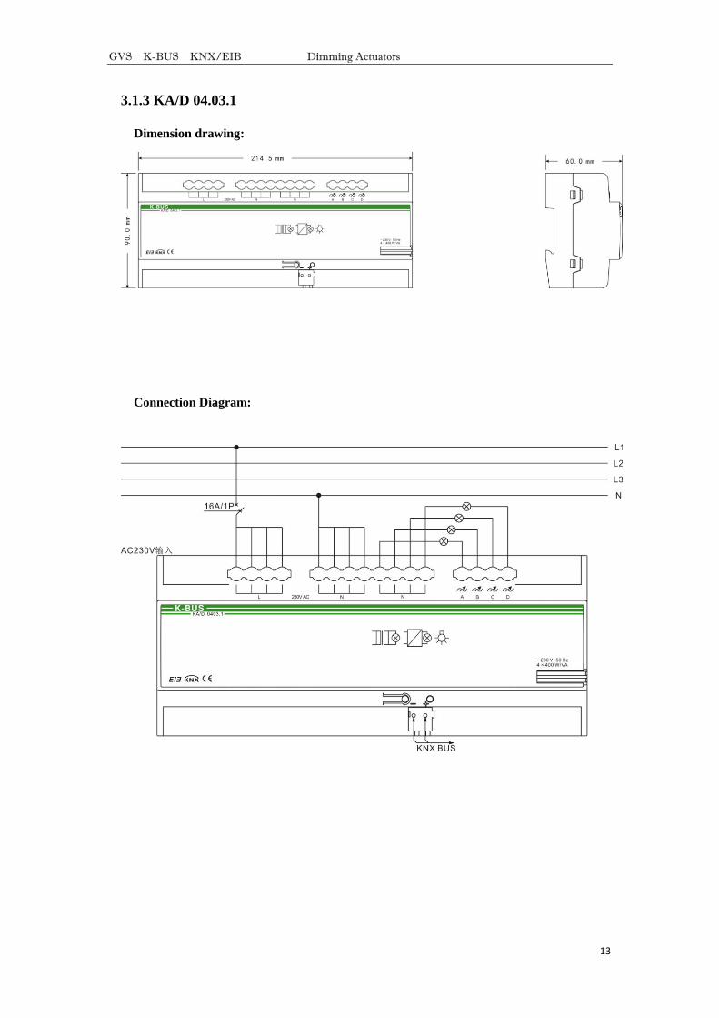
KA/D 04.03.1---4 channels Max. output capacity 400W per channel
Output voltage 230 V AC (50/60Hz), short-circuit and
excess temperature protection
Max. Leakage Loss 5W
Connections EIB/KNX EIB bus connection terminal
Input, Load Circuits Screw terminals
Operation and
display
Button and red LED For assigning physical address
Green LED flashing Indicate the device running normally
Type of
protection
IP 20 , EN 60 529
Temperature Operation -5 °C ... + 45 °C
Storage -25 °C ... + 55 °C
Transport -25 °C ... + 70 °C
Ambient Humidity <93%, except dewing
Mounting On 35mm DIN rail
Dimensions KA/D 01.03.1--- 90×71.5×60 mm
KA/D 02.03.1--- 90×143×60 mm
KA/D 04.03.1--- 90×214.5×60 mm
CE norm In accordance with the EMC guideline and the low voltage guideline
Certification EIB/KNX certified
Weight KA/D 01.03.1--- 0.3kg
GVS K-BUS KNX/EIB Dimming Actuators
8
KA/D 02.03.1--- 0.5kg
KA/D 04.03.1--- 0.75kg
2.1.2 Load type
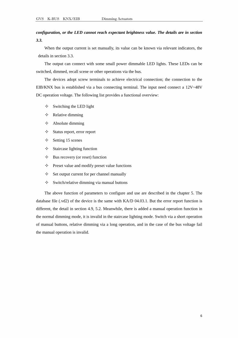
Resistive loads:
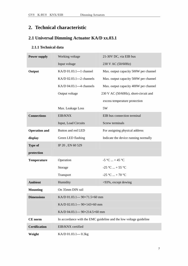
Capacitive loads:
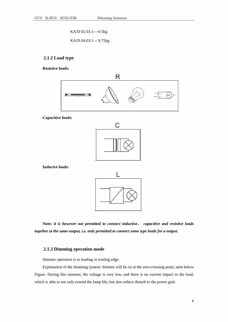
Inducive loads:
Note: it is however not permitted to connect inductive, capacitive and resistive loads
together at the same output, i.e. only permitted to connect same type loads for a output.
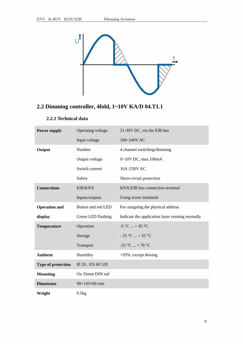
2.1.3 Dimming operation mode
Dimmer operation is in leading or trailing edge.
Explanation of the dimming system: dimmer will be on at the zero-crossing point, seen below
Figure. During this moment, the voltage is very low, and there is no current impact to the load,
which is able to not only extend the lamp life, but also reduce disturb to the power grid.
GVS K-BUS KNX/EIB Dimming Actuators
9
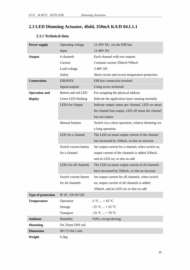
2.2 Dimming controller, 4fold, 1~10V KA/D 04.T1.1
2.2.1 Technical data
Power supply Operating voltage 21-30V DC, via the EIB bus
Input voltage 100~240V AC
Output Number 4 channel switching/dimming
Output voltage 0~10V DC, max.100mA
Switch current 16A /250V AC
Safety Short-circuit protection
Connections EIB/KNX KNX/EIB bus connection terminal
Inputs/outputs Using screw terminals
Operation and
display
Button and red LED For assigning the physical address
Green LED flashing Indicate the application layer running normally
Temperature Operation -5 °C ... + 45 °C
Storage - 25 °C ... + 55 °C
Transport -25 °C ... + 70 °C
Ambient Humidity <93%, except dewing
Type of protection IP 20 , EN 60 529
Mounting On 35mm DIN rail
Dimension 90×143×60 mm
Weight 0.5kg
GVS K-BUS KNX/EIB Dimming Actuators
10
2.3 LED Dimming Actuator, 4fold, 350mA KA/D 04.L1.1
2.3.1 Technical data
Power supply Operating voltage 21-30V DC, via the EIB bus
Input 12-48V DC
Output 4 channels Each channel with two outputs
Current Constant current 350mA/700mA
Load voltage 3-48V DC
Safety Short-circuit and excess temperature protection
Connections EIB/KNX EIB bus connection terminal
Inputs/outputs Using screw terminals
Operation and
display
Button and red LED For assigning the physical address
Green LED flashing Indicate the application layer running normally
LEDs for Output Indicate output status per channel, LED on mean
the channel has output, LED off mean the channel
has not output.
Manual buttons Switch via a short operation, relative dimming via
a long operation
LED for a channel The LED on mean output current of the channel
has increased by 350mA, or else no increase
Switch current button
for a channel
Set output current for a channel, when switch on,
output current of the channels is added 350mA,
and its LED on; or else no add
LEDs for all channels The LED on mean output current of all channels
have increased by 350mA, or else no increase
Switch current button
for all channels
Set output current for all channels, when switch
on, output current of all channels is added
350mA, and its LED on; or else no add
Type of protection IP 20 , EN 60 529
Temperature Operation -5 °C ... + 45 °C
Storage - 25 °C ... + 55 °C
Transport - 25 °C ... + 70 °C
Ambient Humidity <93%, except dewing
Mounting On 35mm DIN rail
Dimension 90×72×64.2 mm
Weight 0.3kg
GVS K-BUS KNX/EIB Dimming Actuators
11
3. Dimension and Connection Diagram
3.1 Universal Dimming Actuator
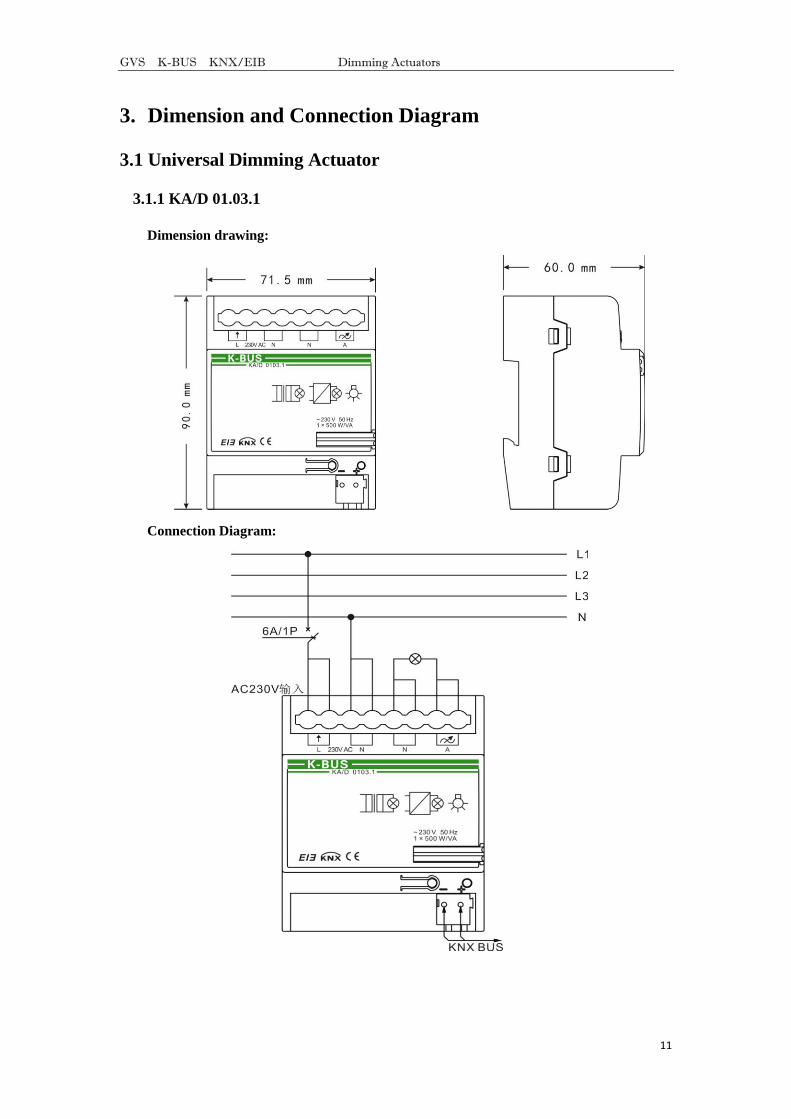
3.1.1 KA/D 01.03.1
Dimension drawing:
Connection Diagram:
GVS K-BUS KNX/EIB Dimming Actuators
12
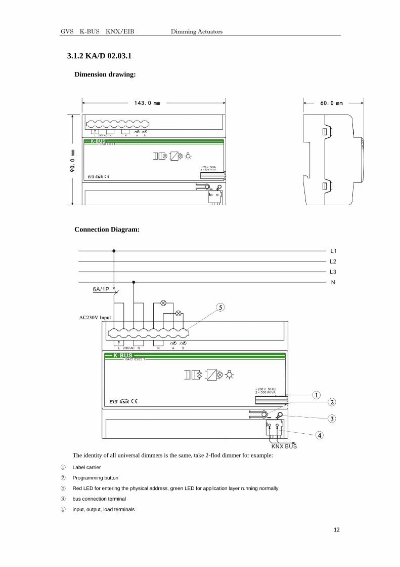
3.1.2 KA/D 02.03.1
Dimension drawing:
Connection Diagram:
The identity of all universal dimmers is the same, take 2-flod dimmer for example:
① Label carrier
② Programming button
③ Red LED for entering the physical address, green LED for application layer running normally
④ bus connection terminal
⑤ input, output, load terminals
GVS K-BUS KNX/EIB Dimming Actuators
13
3.1.3 KA/D 04.03.1
Dimension drawing:
Connection Diagram:
GVS K-BUS KNX/EIB Dimming Actuators
14
3.2 Dimming controller, 4fold, 1~10V
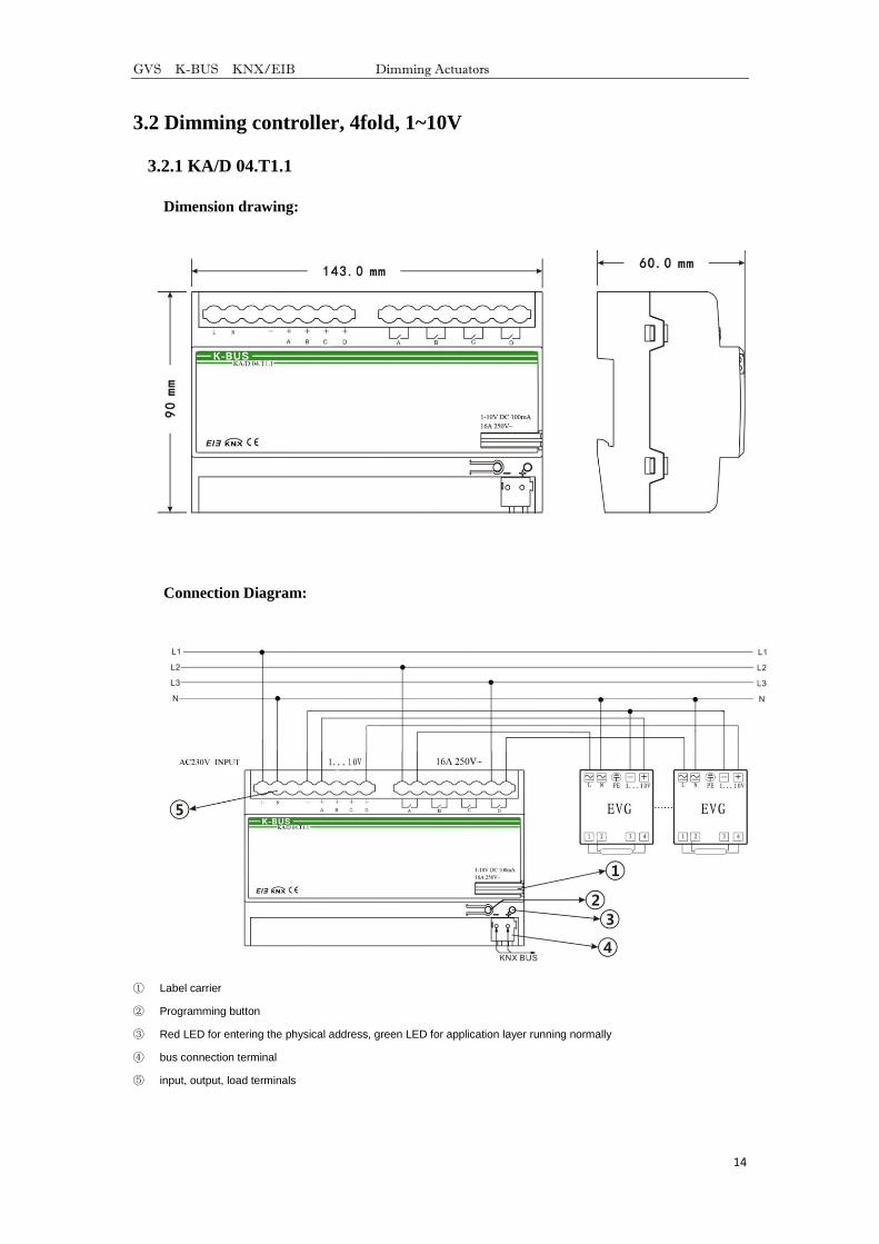
3.2.1 KA/D 04.T1.1
Dimension drawing:
Connection Diagram:
① Label carrier
② Programming button
③ Red LED for entering the physical address, green LED for application layer running normally
④ bus connection terminal
⑤ input, output, load terminals
GVS K-BUS KNX/EIB Dimming Actuators
15
3.3 LED Dimming Actuator, 4fold, 350mA
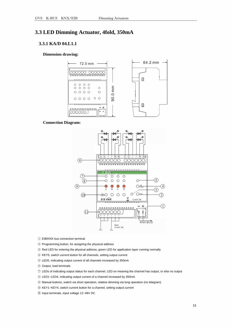
3.3.1 KA/D 04.L1.1
Dimension drawing:
Connection Diagram:
① EIB/KNX bus connection terminal
② Programming button, for assigning the physical address
③ Red LED for entering the physical address, green LED for application layer running normally
④ KEY5, switch current button for all channels, setting output current
⑤ LED5, indicating output current of all channels increased by 350mA
⑥ Output, load terminals
⑦ LEDs of indicating output status for each channel, LED on meaning the channel has output, or else no output
⑧ LED1~LED4, indicating output current of a channel increased by 350mA
⑨ Manual buttons, switch via short operation, relative dimming via long operation (no telegram)
⑩ KEY1~KEY4, switch current button for a channel, setting output current
⑪ Input terminals, input voltage 12~48V DC
GVS K-BUS KNX/EIB Dimming Actuators
16
Manually set the output current is described as follows:
Switching current button for a channel: set output current for the channel, if the button
(KEY1~KEY4) is on, the output current of the channel is increased by 350mA and its LED
(LED1~LED4) is on; if the button is off, the current is not increased and the LED is off.
Switching current button for all channels: set output current for all channels, if the button
(KEY5) is on, the output current of all channels are increased by 350mA and its LED(LED5) is on;
if the button is off, the current are not increased and the LED is off.
The button that set the output current is a dial switch, when it is toggled down, the button is
on and the corresponding LED is also on; when it is toggled up, the button is off and the
corresponding LED is also off.
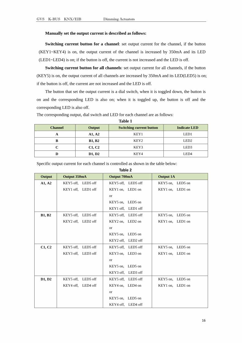
The corresponding output, dial switch and LED for each channel are as follows:
Table 1
Channel Output Switching current button Indicate LED
A A1, A2 KEY1 LED1
B B1, B2 KEY2 LED2
C C1, C2 KEY3 LED3
D D1, D2 KEY4 LED4
Specific output current for each channel is controlled as shown in the table below:
Table 2
Output Output 350mA Output 700mA Output 1A
A1, A2 KEY5 off, LED5 off
KEY1 off, LED1 off
KEY5 off, LED5 off
KEY1 on, LED1 on
or
KEY5 on, LED5 on
KEY1 off, LED1 off
KEY5 on, LED5 on
KEY1 on, LED1 on
B1, B2 KEY5 off, LED5 off
KEY2 off, LED2 off
KEY5 off, LED5 off
KEY2 on, LED2 on
or
KEY5 on, LED5 on
KEY2 off, LED2 off
KEY5 on, LED5 on
KEY1 on, LED1 on
C1, C2 KEY5 off, LED5 off
KEY3 off, LED3 off
KEY5 off, LED5 off
KEY3 on, LED3 on
or
KEY5 on, LED5 on
KEY3 off, LED3 off
KEY5 on, LED5 on
KEY1 on, LED1 on
D1, D2 KEY5 off, LED5 off
KEY4 off, LED4 off
KEY5 off, LED5 off
KEY4 on, LED4 on
or
KEY5 on, LED5 on
KEY4 off, LED4 off
KEY5 on, LED5 on
KEY1 on, LED1 on
GVS K-BUS KNX/EIB Dimming Actuators
17
Note:
The low-power LED dimmer has four channels, each channel is independent and with two
independent outputs. Although the two outputs are independent of each other for a channel,
they are controlled simultaneously.
If outputs of the dimmer connect excessive large current LED lightings, this will lead to
high heating value for the dimmer, however, when the temperature detector of the dimmer
detect certain heating value, the dimming will regulate the output current, thus will affect actual
brightness value of LED lighting. For example, when the heating value exceeds 75℃, the
brightness value of LED will come down, if the heating value continues to rise, the brightness
value will continue to fall. The output is turned off in 90℃. Therefore, the load of the dimmer is
limited as follows:
1. Can connect two outputs of 1A;
2. Can connect four outputs of 700mA;
3. Can connect eight outputs of 350mA;
4. The heating value of one output of 1A equivalent to the heating value of two outputs of
700mA;
5. The heating value of one output of 700mA equivalent to the heating value of four
outputs of 350mA.
According to five above, the outputs can connect different loads in combination, for
example, the dimmer can connect one output of 1A and two outputs of 700mA, or two outputs
of 700mA and six outputs of 350mA etc. (Seen from table 2, the connected load is impossible
occur the combination of 350mA and 1A, and the current of two outputs of each channel is the
same, such as A1, A2.)
When the rated current of the load is higher than the output current of the dimmer, the
brightness of load cannot reach Max value;
When the rated current of the load is lower than the output current of the dimmer, the load
will burn out.
GVS K-BUS KNX/EIB Dimming Actuators
18
4. Application Programming Introduction
It is able to set different parameters to every output channel, and control various targets by
modifying the setup of the internal parameters.
4.1 Switch
The output can be switched ON or OFF by 1 bit data. It is able to set the brightness value as
the last one or a defined one (1%-100%) when switching on the luminaries. It is able to set a
delay time (changing time) to dim UP the luminaries or dim UP gradually in the default period.
When receiving the OFF message, the dimmer will be switched off immediately, or dim DOWN
gradually after a delay time (changing time) or in the default changing period.
4.2 Relative dimming
4 data bits control: the relative dimming command means it is possible to dim UP or DOWN
to the needed brightness value during the set brightness threshold range. It is only valid to dim UP
when the brightness value is smaller than the low threshold value and dim DOWN when the
brightness value is greater than the high threshold value. It is also able to set whether to switch on
the luminaries by the message ―dim UP to a certain value‖ when the output is 0 by this function.
The relative dimming is used to control the relative changes of the brightness by 4 data bits: the
lowest 3 bits are controlling-bit and the highest bit is----- ―1‖ means dim UP, ―0‖ means dim
DOWN.
Explanation of setting relative dimming: (1-7: dim DOWN; 0-8 remain unchanged (stop
dimming); 9-15 dim UP)
Parameter
value
0 1 2 3 4 5 6 7
Dim DOWN Unchange/stop
dimming Down 255 128 64 32 16 8 4
Parameter
value
8 9 10 11 12 13 14 15
Dim UP Unchange/stop
dimming UP 255 128 64 32 16 8 4
4.3 Absolute dimming
8 data bits control: it is able to dim to the needed brightness value by changing the brightness
parameters. The setting of the parameters is similar as relative dimming with the brightness value
range: one low threshold value and one high threshold value. And it is not allowed to change the
brightness value beyond the set range, the max. range is from 0 to 255. This function offers the
possibility to dim UP or DOWN to 0 gradually to the target value by setting the delay time or the
default time.
GVS K-BUS KNX/EIB Dimming Actuators
19
The high and low threshold value limits the total output of the dimmer; any brightness value
beyond the range is not valid.
When the output is 0, it is able to set switching off the luminaries or remaining to a lower
brightness value; and also in this status it is optional to switch on the luminaries by receiving the
message ―absolute dimming‖.
4.4 Status Report
1 data bit: the dimmer offers the possibility whether sending the latest brightness value report
of the controlled target and the changed report of the switch status to the BUS.
4.5 Scene
8 data bits control: the dimmer offers 15 (1-15) scenes for selection. It is possible to set ONE
brightness value and the gradual change time of ON for each scene. After setting, it is easy to call
any favorite scene. 1 in the highest bit of the scene command it means ―saving‖ command, to save
the current brightness value to the relevant scene.
4.6 Preset Value
The dimmer can preset scene, the object directly through 1bit data to transfer the preset scene
or through 1bit data to let favorite scene to replace original preset scene. There are two preset
values per output, there are two brightness values can be transfer for each preset value. Such as in
theater, we need a relatively bright lighting effect when coming in, we can through transfer the
first brightness value to be achieved this effect, when the movie starts playing, we need a
relatively dark lighting effect, we can through transfer the second brightness value to be achieved.
We can return to the previous brightness value when the movie ended.
4.7 Staircase Lighting Function
The dimmer offers the function of staircase lighting control besides the normal lighting
control.
The staircase lighting function serves to switch off the lighting directly until dimming
DOWN to 20% of the brightness value after a set period. It is able to set the brightness of the
luminaries, the duration of the light ON, the time to dim down to 20% separately.
In this function, it uses 1 data bit control the targets directly by setting a permanent fixed
value to the output of the staircase luminaries.
The steps of staircase lighting control: the staircase luminaries will be switched on for a
certain time (this time can be set) if the controlled target receives the message of ―1‖; these
luminaries will be switched on again when receiving another message ―1‖ during this period. The
luminaries will be switched off when they are dimmed down to 20% of the brightness value (the
GVS K-BUS KNX/EIB Dimming Actuators
20
dim down time can be set) after this period, or switch off the luminaries by sending message ―0‖
to the controlled target. The luminaries will be off after dimming down to 20% when receiving the
message ―0‖ (the same dimming down time as above). When enabling the function ―On reception
switch OBJ=0 switch off‖, it is able to use the function "switch off" to turn off the output in the
status of "permanent on", or change the status from "switch on" to "permanent on" (message ―1‖
means ON, ―0‖ means OFF).
4.8 Reset
When the BUS is power off, all the outputs are switched off; the current brightness value will
be saved to the memory of the dimmer. When the BUS voltage is recovered, the brightness status
may be the last brightness value, or the preset brightness value.
When the BUS is power off, it may have the following situation occurring:
In the normal mode, 2 optional behaviors after the BUS voltage recovery are: the last
brightness value before power off, or the set value.
In the staircase lighting mode, the behavior after the BUS voltage recovery is: ON or OFF.
No output when it is OFF; start the behavior ―switch=1‖ when it is ON.
4.9 Error Report
The dimmer offers the possibility of reporting the error status of the system; the data type is 1
byte:
Table 3 Error report of the universal dimmer
Data bit Bit0 Bit1 Bit2 Bit3 Bit4 Bit5
Target Name CH 1 CH 2 CH 3 CH 4
Function Short circuit,
over load
Short circuit,
over load
Short circuit,
over load
Short circuit,
over load
The radiator
temperature
more than
70℃
The radiator
temperature
more than
90℃
Table 4 Error report of the 350mA LED dimmer
Data bit Bit0 Bit1 Bit2 Bit3 —— ——
Target Name B, C channels B, C channels A, D channels A, D channels —— ——
Function
The radiator
temperature more
than 75℃
The radiator
temperature
more than 90℃
The radiator
temperature more
than 75℃
The radiator
temperature
more than 90℃
—— ——
GVS K-BUS KNX/EIB Dimming Actuators
21
4.10 Normal operation signs
1 bit data. The sign will be report periodically to the Bus when the dimmer is working
normally.
5. Parameters Setup Description
5.1 Introduction
2 operation modes (main function) per output:
Normal Dimming
This mode is mainly used to control the normal luminaries system, which can set the output
time and the brightness value of the dimmer, dim UP or DOWN with the function of ―relative
dimming‖, and also call the set brightness values from the scene function, until dim to the required
environment.
Staircase Lighting
The mode is mainly used to control the staircase luminaries. Switch ON the staircase
luminaries and switch OFF automatically after a certain period, or switch OFF by manually.

GVS K-BUS KNX/EIB Dimming Actuators
22
5.2 Parameter Window “Device general”
Fig. 6.1 Parameter window ―Device general‖
“Telegram rate”
This command is used to set the frame speed.
Options: No limit
Delay 100ms
Delay 200ms
……
Delay 700ms
In this system the function of frame speed is unavailable.
“Error report”
This parameter defines the error report status of the system, controlled by 1 byte data bit.
Options: Disable
Enable
There is an error report after the malfunction in the system when selecting ―enable‖,
otherwise, there is no report when selecting ―disable‖. It will send an alarm to switch off the
device if with over temperature, overload or short circuit.
GVS K-BUS KNX/EIB Dimming Actuators
23
In the case of the universal dimmers, the stabilization time of temperature is 1min. in the
program application. When the temperature is higher than 70 ℃ lasted for more than 1min., the
dimmer changes its output into 30% of the current brightness; when the temperature dropped to
60℃, the dimmer changes its output into 50% of the current brightness. When the temperature is
higher than 90℃ lasted for more than 1min., the output turns off and cannot start, until the
temperature drops below 90℃ the output can be restart via sending the output command. If the
temperature fluctuations at the critical point, the stabilization time will re-timing. Only when the
stabilization time (1min.) has elapsed, the current output brightness changes.
In the case of the 350mA LED dimmer, when the radiator temperature is higher than 75 ℃, the
brightness value of LED lighting will come down, if the temperature continues to rise, the
brightness value will continue to fall. The output is turned off in 90℃.
Note: the 350mA LED dimmer only report over temperature. Because of constant current
output, there is not overload, if short-circuit, automatic disconnect output, but no report.
“Sending cycle time in s[1…65535]”
This parameter defines the time interval that the dimmers send the error report by the bus,
which will be started when enabling the error report.
Options: 1…..65535s
“Send object “in operation”
This command is used to send messages ―1‖ or ―0‖ to the BUS periodically to check the
device whether is working or not.
Options: No
Send value “0” cyclically
Send value “1” cyclically
It will not send any telegram with ―No‖; and show the following parameters with ―Send value
„0‟ cyclically‖ or ―Send value '1' cyclically‖ to define the time interval of sending telegram.
Sending cycle time in s[1...65535]
This parameter defines the time interval of the telegram to report the normal working
condition of the dimmer.
Options: 1...65535s
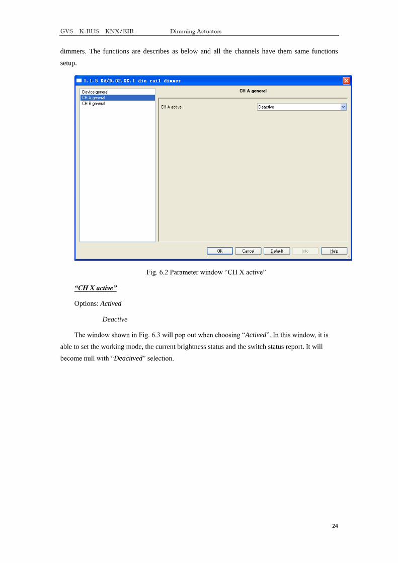
5.3 Parameter Window “CH X active”
The parameter window of ―CH X active‖ can be seen in Fig. 6.2, which activate or deactivate
the output of Channel X. The ―CH X‖ or ―X‖ in the following text means any one output of the
GVS K-BUS KNX/EIB Dimming Actuators
24
dimmers. The functions are describes as below and all the channels have them same functions
setup.
Fig. 6.2 Parameter window ―CH X active‖
“CH X active”
Options: Actived
Deactive
The window shown in Fig. 6.3 will pop out when choosing ―Actived‖. In this window, it is
able to set the working mode, the current brightness status and the switch status report. It will
become null with ―Deacitved‖ selection.
GVS K-BUS KNX/EIB Dimming Actuators
25
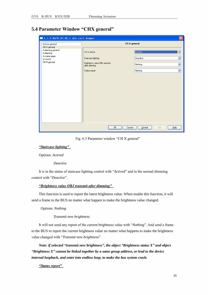
5.4 Parameter Window “CHX general”
Fig. 6.3 Parameter window ―CH X general‖
“Staircase lighting”
Options: Actived
Deactive
It is in the status of staircase lighting control with ―Actived‖ and in the normal dimming
control with ―Deactive‖.
“Brightness value OBJ transmit after dimming”
This function is used to report the latest brightness value. When enable this function, it will
send a frame to the BUS no matter what happen to make the brightness value changed.
Options: Nothing
Transmit new brightness
It will not send any report of the current brightness value with ―Nothing‖. And send a frame
to the BUS to report the current brightness value no matter what happens to make the brightness
value changed with ―Transmit new brightness‖.
Note: if selected “transmit new brightness”, the object “Brightness status X” and object
“Brightness X” cannot be linked together by a same group address, or lead to the device
internal loopback, and enter into endless loop, to make the bus system crash.
“Status report”
GVS K-BUS KNX/EIB Dimming Actuators
26
This function defines whether report the switch status to the BUS when the setup object
―switch‖ is changed. Send ―1‖ to the BUS when the current brightness value is greater than 0; send
―0‖ when the value is equal to 0.
Options: Nothing
It‟s new status
It will not send any report of the current switch status with ―Nothing‖. And send a status
changed report of switch to the BUS with ―It‟s new status‖.
Note: if selected “it’s new status”, the object “Switch status X” and object “Switch X”
cannot be linked together by a same group address, or lead to the device internal loopback, and
enter into endless loop, to make the bus system crash.
5.5 Parameter Window: dimming general
5.5.1 Setting of “CH X dimming general”
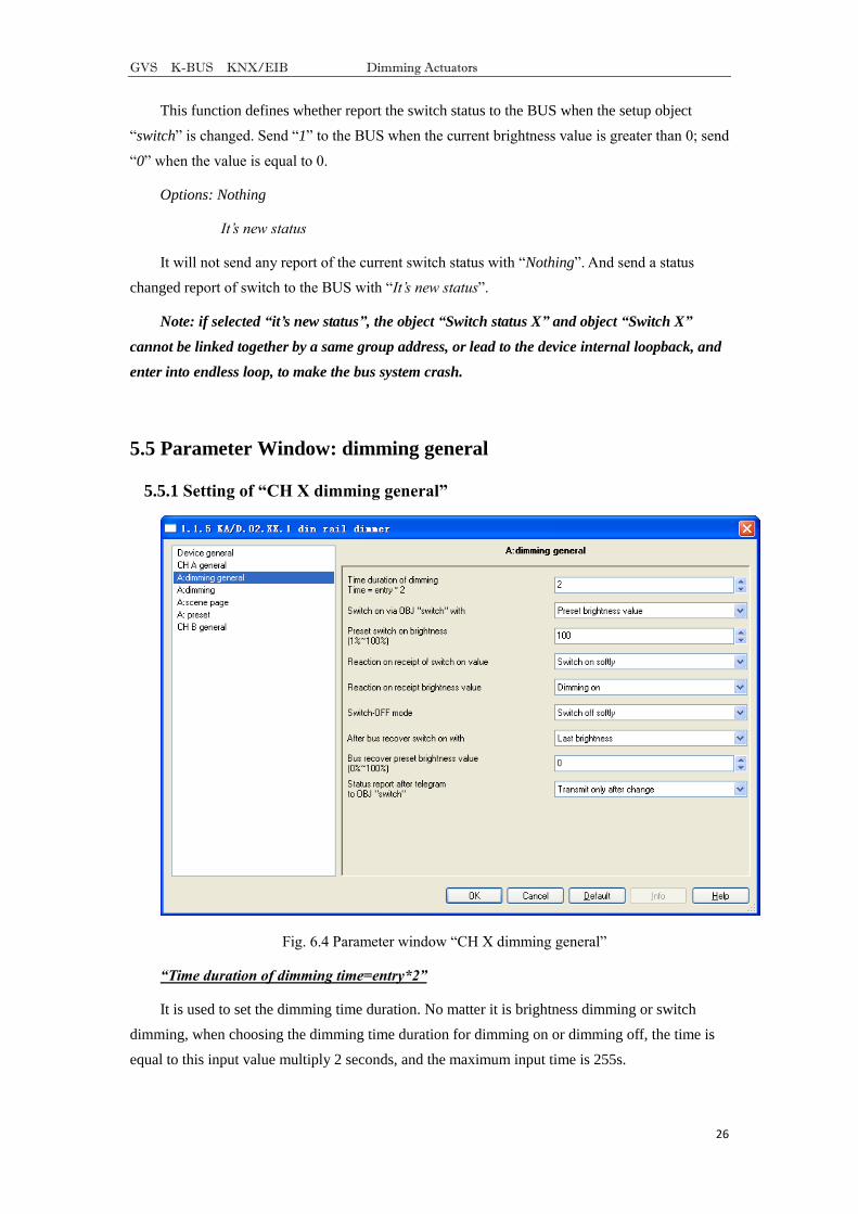
Fig. 6.4 Parameter window ―CH X dimming general‖
“Time duration of dimming time=entry*2”
It is used to set the dimming time duration. No matter it is brightness dimming or switch
dimming, when choosing the dimming time duration for dimming on or dimming off, the time is
equal to this input value multiply 2 seconds, and the maximum input time is 255s.
GVS K-BUS KNX/EIB Dimming Actuators
27
“Switch on via OBJ “switch” with”
It is used to select the brightness value is the last one or the preset one when using the switch
mode to switch on the luminaries.
Options: Preset brightness value
Last brightness value
The option ―Preset brightness value‖ means the brightness value is the preset value when
switching on the luminaries by switch mode. When the brightness low threshold value is greater
than the switch preset value, the brightness value of the luminaries is the low threshold value after
switching on; when the switch preset value is greater than the high threshold, the brightness value
is the high threshold one after switching on. The high and low threshold of the brightness are
shown in the parameter window ―CH X dimming‖, see Fig. 6.5.
The option ―Last brightness value‖ means the brightness value is the last status’ value which
is not equal to 0. If the behavior of switching on the luminaries in switch mode after the BUS reset,
and the luminaries during BUS reset are off, so the brightness value is the default brightness value
128; Other cases, the brightness value is the last status’ value which is not equal to 0 on switching
mode.
“Preset switch on brightness(1%~100%)”
It is used to set the brightness value when switch on the luminaries in switch mode, with the
setting range 1%~100%.
“Reaction on receipt of switch on value”
It shows the time duration to switch on the luminaries in switch mode.
Options: Dimming on
Switch on softly
The option ―Dimming on‖ means the switch dimming time is the input time multiplies 2.
Then option ―Switch softly‖ means the default dimming time is 4s.
“Reaction on receipt brightness value”
It is used to set the brightness value in the brightness dimming mode.
Options: Dimming on
Switch on softly
The option ―Dimming on‖ means the brightness dimming time is the input time multiplies 2.
Then option ―switch softly‖ means the default dimming time is 4s.
“Switch-off mode”
GVS K-BUS KNX/EIB Dimming Actuators
28
It shows the time duration to switch off the luminaries in switch dimming mode.
Options: Dimming off
Switch off softly
Switch off instantly
The option ―Dimming off‖ means the switch dimming time is the input time multiplies 2. The
option ―switch softly‖ means the default dimming time is 4s. The option ―switch off instantly‖
means the luminaries are switch off immediately.
“After bus recover switch on with”
It means in the normal situation, the behavior after the BUS reset is the brightness value
before power off or the preset value.
Options: Preset brightness value
Last brightness value
The option ―Preset brightness value‖ means the brightness value after the BUS power
recovers is the input preset brightness value in the ―bus recover preset brightness value
(0%~100%)‖. If the input preset value is smaller than the low threshold, the value after the BUS
power recovery is the low threshold; if the preset input value is greater than the high threshold, the
value after the BUS power recovery is the high threshold. The high and low threshold are shown
in the parameter window ―CH X dimming‖, see Fig. 6.5.
The option ―Last brightness value‖ means the brightness value is the last value before power
off after BUS power recovery. It also carry out a bus reset operation after downloading the
parameters.
“Bus recover preset brightness value(0%~100%)”
It is used to set the brightness value during the BUS power recovery, and the range is 0%~
100%.
“Status report after telegram to obj “switch””
It is a backup parameter, do not care it.
GVS K-BUS KNX/EIB Dimming Actuators
29
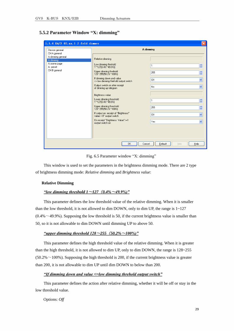
5.5.2 Parameter Window “X: dimming”
Fig. 6.5 Parameter window ―X: dimming‖
This window is used to set the parameters in the brightness dimming mode. There are 2 type
of brightness dimming mode: Relative dimming and Brightness value:
Relative Dimming
“low dimming threshold 1~127(0.4%~49.9%)”
This parameter defines the low threshold value of the relative dimming. When it is smaller
than the low threshold, it is not allowed to dim DOWN, only to dim UP, the range is 1~127
(0.4%~49.9%). Supposing the low threshold is 50, if the current brightness value is smaller than
50, so it is not allowable to dim DOWN until dimming UP to above 50.
“upper dimming threshold 128~255(50.2%~100%)”
This parameter defines the high threshold value of the relative dimming. When it is greater
than the high threshold, it is not allowed to dim UP, only to dim DOWN, the range is 128~255
(50.2%~100%). Supposing the high threshold is 200, if the current brightness value is greater
than 200, it is not allowable to dim UP until dim DOWN to below than 200.
“If dimming down and value <=low dimming threhold output switch”
This parameter defines the action after relative dimming, whether it will be off or stay in the
low threshold value.
Options: Off
GVS K-BUS KNX/EIB Dimming Actuators
30
To low threshold value
Supposing the low threshold is 50. If it is ―Off‖, it will switch off the luminaries when dim
DOWN to 50; if it is ―To low threshold value‖, the value of the luminaries will remain the same
even when dimming DOWN to 50. However, no matter whether it is ―Off‖ or ―To low threshold
value‖, if the low threshold of the relative dimming is smaller than that of the brightness, it will
switch off the luminaries automatically when dimming DOWN to the low threshold of the
brightness value; if the high threshold of the brightness is greater than relative high threshold, it is
only possible to dim UP to the high threshold of the brightness. (The high and low threshold value
will limit the total brightness value of the dimmer, see more details in the below description.)
“Output switch on after receipt of dimming up telegram”
It tells that whether it is possible to switch on the luminaries when receiving the ―dimming
up‖ message from relative dimming if the output is 0.
Options: No
Yes
Supposing the current output is 0. If it is ―NO‖, the output still remain 0 even when the target
receives the message ―dimming UP‖; if it is ―YES‖, it will dim the luminaries to the modified
value when receiving the ―dimming up‖ message. If the value after dimming up is smaller than the
brightness low threshold, it will be dimmed to the low threshold directly. If the value after
dimming up is greater than the brightness high threshold, it will be dimmed to the high threshold
directly.
Brightness Value
The high and low threshold value limits the high and low output value. It is not allowed to
change the brightness value if it is beyond the high and low threshold which will be invalid. For
example in Fig. 6.5 the value is set as 1~255. If the low threshold value is set as 50 and the high
threshold is 200, the brightness value ―210‖ will be invalid. The luminaries will be dimmed from
the low threshold directly when the brightness value goes up from 0; the luminaries will be
dimmed from the high threshold directly when the brightness values goes down from 255.
“low dimming threshold 1~127(0.4%~49.9%)”
This function defines the low threshold of the dimmer, and the range is 1~127. It is going to
start dimming from the low threshold. Supposing the current brightness value is 0; the low
threshold is 50 and the high threshold is 200. If receiving the message ―30‖, the brightness value
will go to 50 directly without gradual change; if receiving the message ―60‖, so the brightness
value will first go to 50 and then go up to 60 gradually; if the current value is 100 and the target
value is 30, so the value will go from 100 to 50 and the brightness value is 50.

GVS K-BUS KNX/EIB Dimming Actuators
31
“upper dimming threshold 128~255(50.2%~100%)”
This function defines the high threshold of the dimmer, and the range is 128~255. Supposing
the low threshold is 50, and the high threshold is 200. If the input brightness value is greater than
200, it will go to 200 directly.
“If output on : receipt of “brightness value=0”output switch”
This function defines it is available or not to switch off the output by the defined brightness
vale ―0‖.
Options: Off
To low threshold value
The option ―Off‖ means the output is 0 when the brightness value is 0.The option ―To low
threshold value‖ means the output is the low threshold when the value is 0.
“On receipt “brightness value”>=1 output switch on”
This function defines it is available or not to switch on the output by brightness dimming
mode when the output is 0.
Options: No
Yes
The option ―No‖ means the dimmer remains the output ―0‖ when receiving the message of
100 if the output is 0. The option ―Yes‖ means the output is the input brightness value when the
receiving value is greater or equals to 1; if the input brightness value is smaller than the brightness
low threshold, the output is the brightness low threshold.
GVS K-BUS KNX/EIB Dimming Actuators
32
5.5.3 Parameter Window “X: scene page”
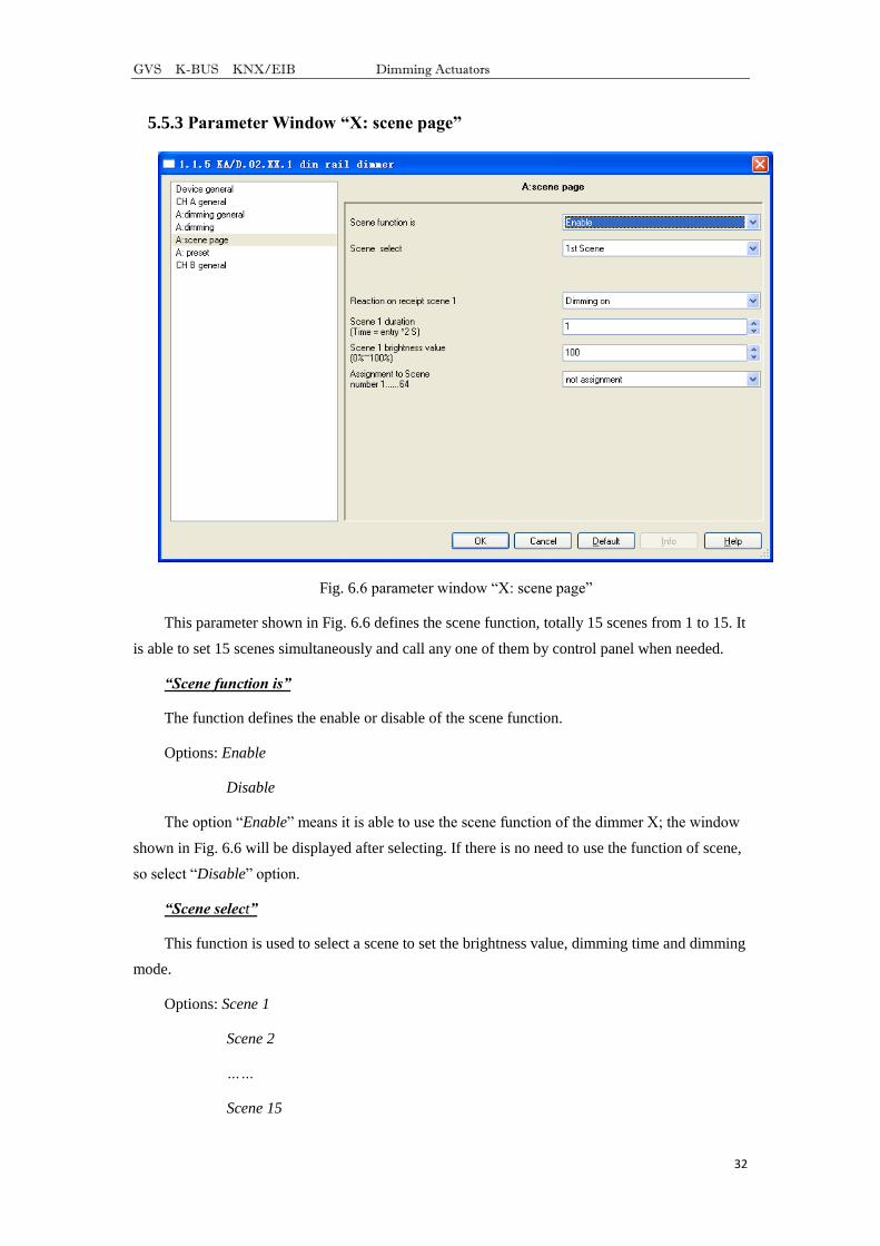
Fig. 6.6 parameter window ―X: scene page‖
This parameter shown in Fig. 6.6 defines the scene function, totally 15 scenes from 1 to 15. It
is able to set 15 scenes simultaneously and call any one of them by control panel when needed.
“Scene function is”
The function defines the enable or disable of the scene function.
Options: Enable
Disable
The option ―Enable‖ means it is able to use the scene function of the dimmer X; the window
shown in Fig. 6.6 will be displayed after selecting. If there is no need to use the function of scene,
so select ―Disable‖ option.
“Scene select”
This function is used to select a scene to set the brightness value, dimming time and dimming
mode.
Options: Scene 1
Scene 2
……
Scene 15

GVS K-BUS KNX/EIB Dimming Actuators
33
The setting parameters for the other 15 scenes are shown as below:
“Reaction on receipt scene Y”
The function defines the dimming mode of the set scene. Y means the scene that needs
setting, 1~15. The Y shown as below has the same meaning.
Options: Dimming on
Switch on softly
The option ―Dimming on‖ means the set scene dimming time is the set time of the parameter
―Scene Y duration (time=entry*2s)‖: the input time multiplies 2. The option ―Switch on softly‖
means the scene dimming time is the default time ―4S‖.
“Scene Y duration(time=entry*2 S)”
This function defines the dimming time of the set scene, which is the input value multiplies
2s; the maximum input time is 255s.
“Scene Y brightness value(0%~100%)”
This function defines the brightness value of the set scene, with range from 1% to 100%.
“Assignment to Scene number 1…64”
This function distributes the scene number of the set scene that means the communication
object ―Scene/save X‖ will call the scene by the allocated scene number.
Options: Not assignment
Assignment to scene 1
Assignment to scene 2
……
Assignment to scene 64
Note: the parameter setting option is 1~64 field number or unallocated.
GVS K-BUS KNX/EIB Dimming Actuators
34
5.5.4 Parameter Window “X: preset”
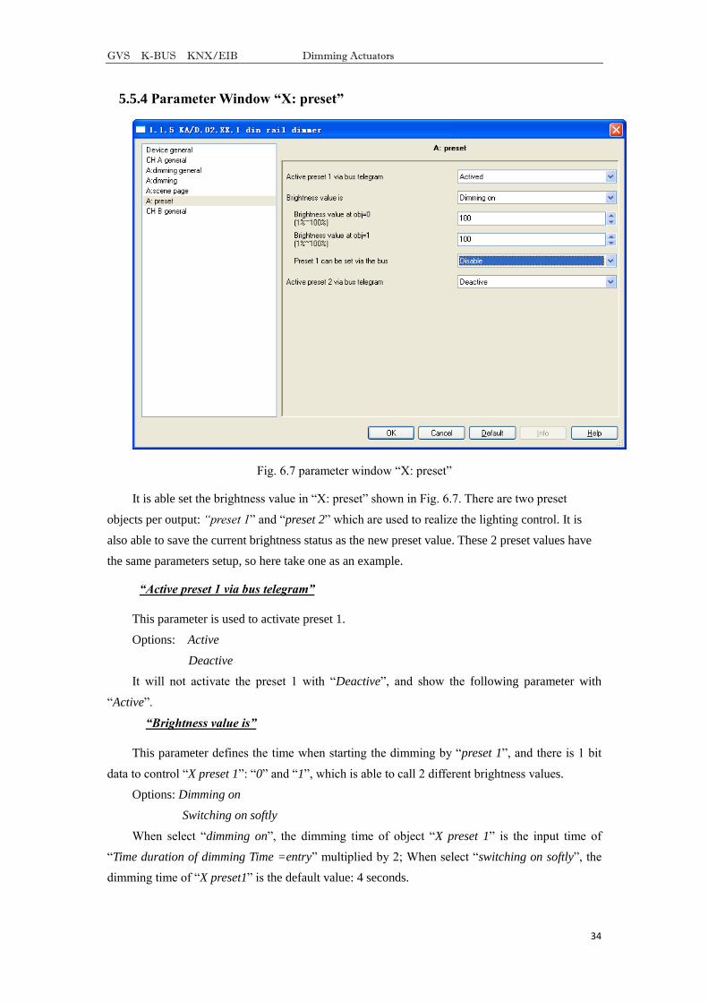
Fig. 6.7 parameter window ―X: preset‖
It is able set the brightness value in ―X: preset‖ shown in Fig. 6.7. There are two preset
objects per output: “preset 1‖ and ―preset 2‖ which are used to realize the lighting control. It is
also able to save the current brightness status as the new preset value. These 2 preset values have
the same parameters setup, so here take one as an example.
“Active preset 1 via bus telegram”
This parameter is used to activate preset 1.
Options: Active
Deactive
It will not activate the preset 1 with ―Deactive‖, and show the following parameter with
―Active‖.
“Brightness value is”
This parameter defines the time when starting the dimming by ―preset 1‖, and there is 1 bit
data to control ―X preset 1‖: ―0‖ and ―1‖, which is able to call 2 different brightness values.
Options: Dimming on
Switching on softly
When select ―dimming on‖, the dimming time of object ―X preset 1‖ is the input time of
―Time duration of dimming Time =entry‖ multiplied by 2; When select ―switching on softly‖, the
dimming time of ―X preset1‖ is the default value: 4 seconds.
GVS K-BUS KNX/EIB Dimming Actuators
35
“Brightness value at obj=0(1%~100%)”
This parameter defines the brightness value when receiving ―0‖ by ―X preset 1‖.
Option: 1~100%
“Brightness value at obj=1(1%~100%)”
This parameter defines the brightness value when receiving ―1‖ by ―X preset 1‖.
Option: 1~100%
“Preset 1 can be set via the bus”
This parameter defines the possibility to change the preset value. It is able change the preset
value with ―enable‖ and also start the communication object ―Set preset 1‖, which is used to save
the current switch status as the new preset value. It will save the current brightness status to the
―brightness value at obj=0‖ and replace that value with ―0‖; will save the current brightness status
to the ―brightness value at obj=1‖ and replace that value with ―1‖.
Options: Enable
Disable
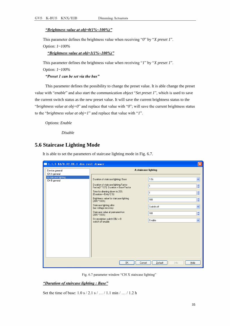
5.6 Staircase Lighting Mode
It is able to set the parameters of staircase lighting mode in Fig. 6.7.
Fig. 6.7 parameter window ―CH X staircase lighting‖
“Duration of staircase lighting : Base”
Set the time of base: 1.0 s / 2.1 s / … / 1.1 min / … / 1.2 h
GVS K-BUS KNX/EIB Dimming Actuators
36
“Duration of staircase lighting : Factor”
Set the time of factor: 1~255 S
When switch on the staircase luminaries by ―switch‖ mode, the ON duration time is:
duration=base*factor. It will switch off the luminaries when the brightness goes down to 20%
gradually after the ON duration time.
“Time for dimming down to 20% (Duration=Entry*2)”
This function defines the time that the brightness value of the staircase lamps goes down to
20%: Duration=Entry*2. The maximum input value is 255s.
The luminaries will be switched off when the brightness value of the staircase goes down to
20%.
“Brightness value for staircase lighting(20%~100%)”
The function defines the brightness value of the staircase when switching on the luminaries
by ―switch‖ mode.
“Staircase lighting after bus voltage recovery”
The function defines the status of the staircase luminaries after the BUS power recovery.
Options: Switch on
Switch off
The option ―Switch on‖ means switch on the staircase luminaries after the BUS power
recovery; duration=base*factor. It is to use the parameter ―Time for dimming down to 20%
(Duration=Entry*2)‖ to set the DOWN time. The option ―Switch off‖ means switch off the
staircase lamps after the BUS power recovery.
“Staircase value at permanent-on(20%~100%)”
The function defines the output status of the staircase luminaries as a fixed brightness value.
It will not switch off the staircase luminaries without receiving the OFF message from ―permanent
on‖. ―permanent on‖ is another output mode of the staircase luminaries. The DOWN time of
turning off the luminaries is set by the parameter ―Time for dimming down to 20%
(Duration=Entry*2)‖. It will switch off the luminaries when going down to 20%. The range is
20%~100%.
“On reception switch OBJ=0 switch off enable”
Options: Enable
Disable
It is able to send off command out by ―switch‖ no matter in switch or permanent on mode
with ―Enable‖; but only stop outputting ―Permanent on‖ by using ―permanent on‖ to send OFF
GVS K-BUS KNX/EIB Dimming Actuators
37
command in the ―permanent on‖ lighting mode with ―Disable‖.
Note: In the switch output mode, it can start the “permanent on” output mode, but can’t be
performed the close operation of “permanent on” when you did not start the the “permanent
on” output mode.
6. Communication Object Description
Communication object is the media of devices on the bus communicate with other device,
that is, just communication object can communicate with the BUS. The role of each
communication objects as following.
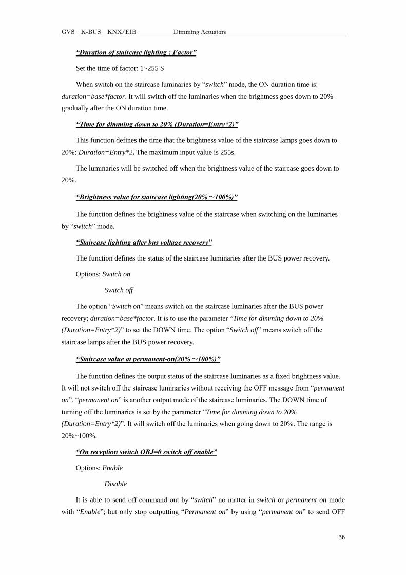
6.1 Communication object of “Device General”
There are 2 communication objects in "Device General" in Fig. 7.1 and functions are shown
in table 7.1.
Fig. 7.1 Communication object of ―Device General‖
Note: “C” in “Flag” column in the below table means that the object has a normal link to
the bus; “W” means the object value can be modified via the bus; “R” means the value of the
object can be read via the bus; “T” means that a telegram is transmitted when the object value
has been modified; “U” means that value response telegrams are interpreted as a write command,
the value of the object is updated.
No. Function Object Name Data Flags
12 In operate In operate 1bit C,T
This object is used to declare the working condition by sending ―1‖ or ―0‖ to the bus
cyclically, which is enabled when selecting ―send value '0' cyclically‖ or ―send value '1' cyclically‖
in the parameter ―Send object 'in operation'‖ and disabled when selecting ―no‖. It will send ―0‖
with option ―send value '0' cyclically‖ and ―1‖ with ―send value '1' cyclically‖.
11 Report error of device Error report 1byte C, R,T
This object is used to report the error status of the system. It will be disabled with ―Error
report‖, and report error information when the system has the malfunction with the option
―Enable‖. It will also send an alarm to switch off the device with over temperature, overload or
short circuit.
Assuming an 8-bit command (telegram code) as: 76543210
Universal dimmer
8 bits are 0, that is the telegram "0" – the system working normally
No. 0 is 1 – Channel 1 short circuit or over load

GVS K-BUS KNX/EIB Dimming Actuators
38
No. 1 is 1 – Channel 2 short circuit or over load
No. 2 is 1 – Channel 3 short circuit or over load
No. 3 is 1 – Channel 4 short circuit or over load
No. 4 is 1 – the radiator temperature more than 70℃
No. 5 is 1 – the radiator temperature more than 90℃
Other are not used
350mA LED dimmer
8 bits are 0, that is the telegram "0" – the system working normally
No. 0 is 1 –the radiator temperature more than 75℃ for B,C channels (middle PCB)
No. 1 is 1 –the radiator temperature more than 90℃ for B,C channels (middle PCB)
No. 2 is 1 –the radiator temperature more than 75℃ for A,D channels (bottom PCB)
No. 3 is 1 –the radiator temperature more than 90℃for A,D channels (bottom PCB)
Other are not used
Table 7.1 Communication object table of Device General
6.2 General communication object of “Dimming Actuator”
Fig. 7.2 General communication object for each channel
No Function Object Name Data Type Flags
1 Switch status X OUTPUT X 1bit C,R, T
This object is used to report the status of the current switch to the bus. The dimmer will send
―1‖ to the bus when the value of the brightness is larger than 0, ―0‖ to the bus with value of ―0‖.
The object will be enabled when selecting ―It is new status‖ in the parameter ―Status report‖.
0 Switch X OUTPUT X 1bit W,C
This object is used to receive the switch command to switch the dimmer actuator. It will
switch on the dimmer actuator with ―1‖, off with ―0‖.
4 Brightness status X OUTPUT X 1byte C,R,T
This object is used to send the brightness status of the current output to the bus whatever
causes the changes of the value. The object will be enabled when selecting ―Transmit new
brightness‖ in the parameter ―Brightness value OBJ transmit after dimming‖.
3 Brightness X OUTPUT X 1byte W,C
It is used to receive the brightness value to switch the dimmer actuator, switching on the
actuator when the received value is larger than 0, off or stay to the lower threshold value with ―0‖,
GVS K-BUS KNX/EIB Dimming Actuators
39
which is defined by the parameter setup in the brightness value dimming.
2 Relative dimming X OUTPUT X 4bit W,C
This object is used to dim up or down the outputs. It will dim down when the input value is
from 1 to 7. During this range, smaller amplitude of dimming down with larger value; that means
it will dim down to the biggest amplitude with 1, while to the smallest amplitude with 7, and 0
means stop dimming down. It will dim up when the input value is from 9-15. During this range,
smaller amplitude of dimming up with larger value; that means it will dim up to the biggest
amplitude with 9, while to the smallest amplitude with 15, and 8 means stop dimming up.
Table 7.2 General communication object table for each channel
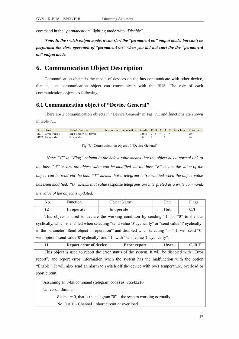
6.3 Scene function communication object of “Dimming Actuator”
Fig. 7.3 Scene function communication object
No. Function Object name Data type Flag
6 Scene /save X OUTPUT X 1Byte W,C
This object is used to send an 8bit command to transfer or save the scene. This object is
opening when on enable scene function. The mean of 8bit as following:
Set up an 8bit command (binary code) as: FXNNNNNN
F: ―0‖ transfer scene; F: ‖1‖ save scene;
X:Un-used, not affect the results;
NNNNNN:scene number(0…63)
The parameter setup is 1-64.
Table 7.3 Scene function communication object
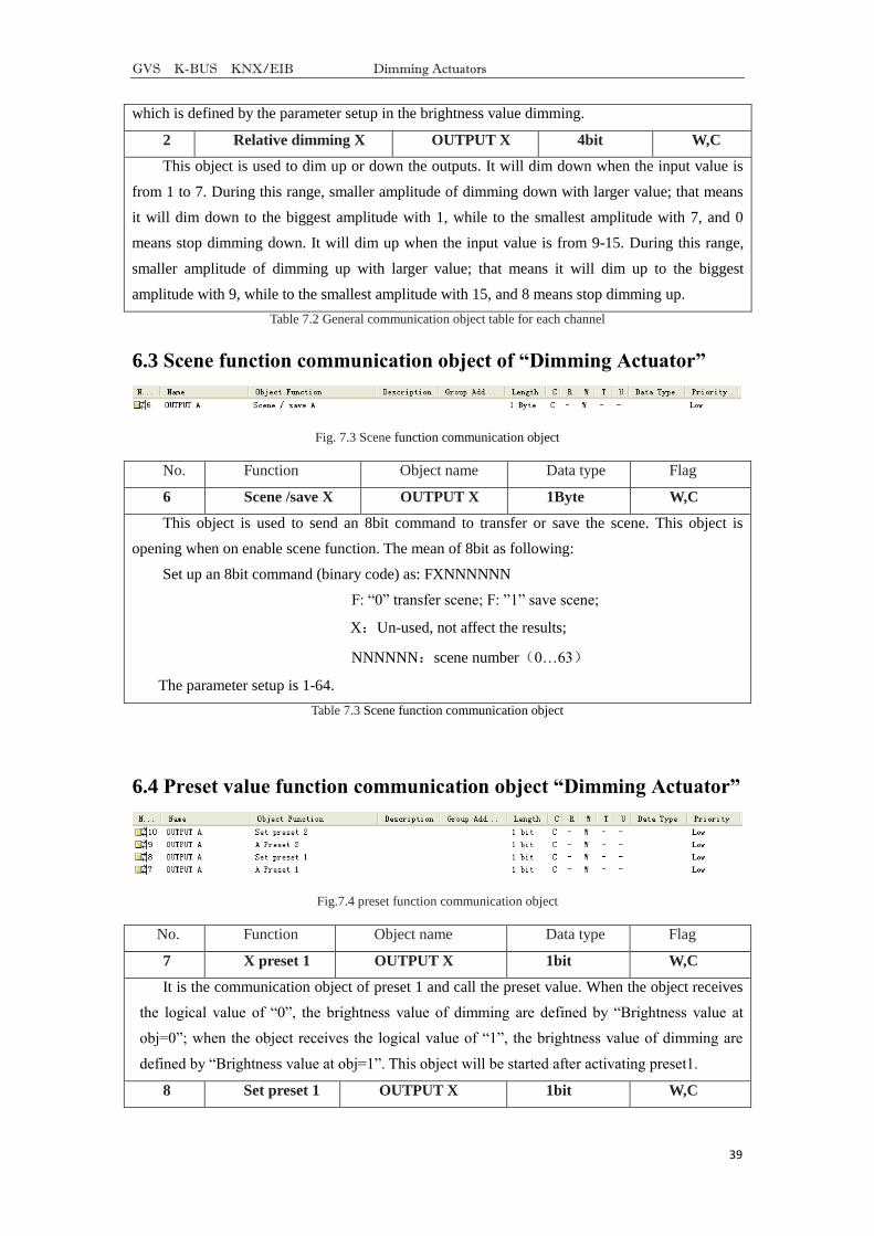
6.4 Preset value function communication object “Dimming Actuator”
Fig.7.4 preset function communication object
No. Function Object name Data type Flag
7 X preset 1 OUTPUT X 1bit W,C
It is the communication object of preset 1 and call the preset value. When the object receives
the logical value of ―0‖, the brightness value of dimming are defined by ―Brightness value at
obj=0‖; when the object receives the logical value of ―1‖, the brightness value of dimming are
defined by ―Brightness value at obj=1‖. This object will be started after activating preset1.
8 Set preset 1 OUTPUT X 1bit W,C
GVS K-BUS KNX/EIB Dimming Actuators
40
This object is used to modify brightness value of preset1. It will start the parameter ―preset1
can be set via the bus‖ with ―Enable‖. Via this object can save current brightness status as new
preset value. It will save the current brightness value to ‖brightness value at obj=0‖ with ―0‖, that
is to replace the is value; It will save the current brightness value to ‖brightness value at obj=1‖
with ―1‖, that is to replace the is value.
9 X preset 2 OUTPUT X 1bit W,C
It is the communication object of preset 2 and calls the preset value. When the object receives
the logical value of ―0‖, the brightness value of dimming are defined by ―Brightness value at
obj=0‖; when the object receives the logical value of ―1‖, the brightness value of dimming are
defined by ―Brightness value at obj=1‖. This object will be started after activating preset 2.
10 Set preset 2 OUTPUT X 1bit W,C
This object is used to modify brightness value of preset 2. It will start the parameter ―preset 2
can be set via the bus‖ with ―Enable‖. Via this object can save current brightness status as new
preset value. It will save the current brightness value to ―brightness value at obj=0‖ with ―0‖, that
is to replace the is value; It will save the current brightness value to ‖brightness value at obj=1‖
with ―1‖, that is to replace the is value.
Form7.4 Preset value function communication object
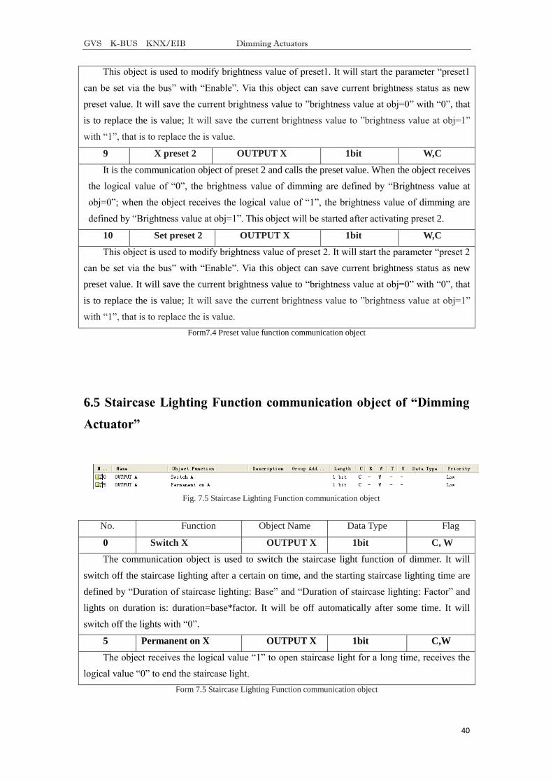
6.5 Staircase Lighting Function communication object of “Dimming
Actuator”
Fig. 7.5 Staircase Lighting Function communication object
No. Function Object Name Data Type Flag
0 Switch X OUTPUT X 1bit C, W
The communication object is used to switch the staircase light function of dimmer. It will
switch off the staircase lighting after a certain on time, and the starting staircase lighting time are
defined by ―Duration of staircase lighting: Base‖ and ―Duration of staircase lighting: Factor‖ and
lights on duration is: duration=base*factor. It will be off automatically after some time. It will
switch off the lights with ―0‖.
5 Permanent on X OUTPUT X 1bit C,W
The object receives the logical value ―1‖ to open staircase light for a long time, receives the
logical value ―0‖ to end the staircase light.
Form 7.5 Staircase Lighting Function communication object