Embed Size (px)
Citation preview

Guangzhou Video-star Electronics Industrial Co., Ltd
www.video-star.com.cn [email protected] Tel.:(8620)39338986
Fax:(8620)39338465
K-BUS○R KNX IP Router
User manual-Ver.1
BNIPR-00/00.1
KNX/EIB Intelligent Installation Systems

GVS K-BUS○R KNX/EIB KNX IP Interface
2
www.video-star.com.cn [email protected] Tel.:(8620)39338986
Fax:(8620)39338465
Contents
1. Summary------------------------------------------------------------------------------------------------------------------------------ 3
1.1 Function overview----------------------------------------------------------------------------------------------------------------3
1.2 Tunneling--------------------------------------------------------------------------------------------------------------------------5
1.3 Routing---------------------------------------------------------------------------------------------------------------------------- 5
1.4 KNX IP Routers------------------------------------------------------------------------------------------------------------------ 5
2. Technical Properties & Dimension and Circuit Diagram--------------------------------------------------------------------5
2.1 Technical data---------------------------------------------------------------------------------------------------------------------5
2.2 Dimension diagram-------------------------------------------------------------------------------------------------------------- 7
2.3 Circuit diagram------------------------------------------------------------------------------------------------------------------- 7
3. Planning and Application---------------------------------------------------------------------------------------------------------- 9
3.1 Operation Modes----------------------------------------------------------------------------------------------------------------- 9
3.1.1 Normal Mode----------------------------------------------------------------------------------------------------------------9
3.1.2 The Function Button--------------------------------------------------------------------------------------------------------9
3.1.3 The Programming Button and LED-------------------------------------------------------------------------------------10
3.2 KNX Telegrams in the IP Network-------------------------------------------------------------------------------------------10
3.2.1 The IP Router in a Network Installation--------------------------------------------------------------------------------11
3.2.2 The IP Router as an Area Coupler-------------------------------------------------------------------------------------- 11
3.2.3 The IP Router in a Mixed System--------------------------------------------------------------------------------------- 11
3.2.4 The IP Router as A Line Coupler--------------------------------------------------------------------------------------- 12
4. Parameter setting description in the ETS------------------------------------------------------------------------------------- 13
4.1 Physical Address Assignment------------------------------------------------------------------------------------------------- 13
4.2 General--------------------------------------------------------------------------------------------------------------------------- 14
4.3 IP Configuration---------------------------------------------------------------------------------------------------------------- 15
4.4 KNXMulticasting Address----------------------------------------------------------------------------------------------------16
4.5 Setting for coupler-------------------------------------------------------------------------------------------------------------- 18
4.5 Main Line------------------------------------------------------------------------------------------------------------------------ 19
4.6 Sub Line--------------------------------------------------------------------------------------------------------------------------20
5. State of Delivery-------------------------------------------------------------------------------------------------------------------- 22

GVS K-BUS○R KNX/EIB KNX IP Interface
3
www.video-star.com.cn [email protected] Tel.:(8620)39338986
Fax:(8620)39338465
1. Summary
The IP Router can be used as line or backbone coupler. It provides a data connection between the upper
KNXnet/IP line (main line or backbone) and the lower TP KNX bus line (sub line). The basic functionality of the
IP Router is to couple the Ethernet with one or more KNX-TP lines. The IP Router features a galvanic isolation
between the Ethernet and the KNX-TP line(s). Due to its flexibility the IP Router can be used as a line coupler e.g.
to connect several KNX TP lines via Ethernet. And it can be used as a backbone coupler to connect several TP
areas or different TP installation systems via Ethernet.
The main task of the IP Router is filtering the traffic according to the installation hierarchy. For group
oriented communication the traffic is filtered according to the built-in filter tables.
With the ETS or any other KNX compatible commissioning tool the IP Router can be used as the
programming interface. For this purpose the device provides up to 4 additional physical addresses that can be used
for tunneling. The IP Router has no KNX communication objects for itself.
The IP Router is a Tunneling and Routing device. These features are described in the following sections in
detail. The device front panel consists of seven LEDs and two buttons as illustrated below. The device offers a
detailed internal diagnosis by displaying all operational states in different Operation Modes with three pairs of
LEDs. The LEDs show the variety of device states like Bus OK, traffic, errors/faulty communication NACK,
BUSY on the bus, state of the filter table, and etc.
The IP Router is a modular installation device. It can be installed in the distribution board on 35mm
mounting rails according to EN 60 715.
This manual provides the technical information about the IP Router as well as assembly and programming in
detail for users, and explains how to use the interface device by the application examples.
1.1 Function overview
The IP Router has the follow functions:

GVS K-BUS○R KNX/EIB KNX IP Interface
4
www.video-star.com.cn [email protected] Tel.:(8620)39338986
Fax:(8620)39338465
The IP Router is one of the rare KNX IP routers on the market that supports long messages up to 240 bytes. In
combination with the line coupler and the long messages are made possible (e.g. for energy metering
applications).
The IP Router favourably replaces a line coupler or an area coupler. Using LAN as a fast medium to exchange
telegrams between lines and/or areas is the great advantage.
The IP Router works without external power supply.
Providing tunneling protocols and a connection point for the ETS (or any other tool to enable commissioning
and monitoring) the ETS address for tunneling is not necessarily the one that is already configured. Four
parallel connections are possible, one separate address for each and every connection.
IACK on own sent out messages (ETS configurable).
After no IACK response on a sent message the IP Router can repeat it up to three times. For physically
addressed or for group addressed telegrams this can be configured via ETS independently. In case of an IACK
response there will be no repetition. The failure mechanism of a negative IACK or BUSY is still maintained
hereby.
Programmable automatic switch on of the filter table after timeout.
For a predefined amount of time (ETS configurable) it is possible to switch off the filter table with pressing a
button on the device. So, without reconfiguring the device with the ETS the filter table can be switched off by
a button press which is necessary for running fast diagnostics on site. Filtering of messages can temporarily be
disabled by pressing the “Function” button. This eases commissioning and debugging of the system. Without
an ETS download a temporary access to other lines is possible. After the timeout an automatic switching the
filter table on is implemented (the timeout is configurable in the ETS). This avoids forgetting to reactivate the
filter.
UPnP is available to discover the device in the IP network. That is only possible with a proper network
installation in terms of topology. With the KNXnet/IP Search Request the ETS can recognize the device as a
communication interface.
For networks with a high bus load a high internal amount of communication buffers is suitable.
The IP Router is featuring a high internal amount of communication buffers being capable of smoothing peeks
in the communication load course.
The IP Router’s ETS database entries are available for the ETS3.0f and upward.
The IP Router supports KNXnet/IP, ARP, ICMP, IGMP, HTTP, UPnP discovery, UDP/IP, TCP/IP, DHCP
und Auto IP.

GVS K-BUS○R KNX/EIB KNX IP Interface
5
www.video-star.com.cn [email protected] Tel.:(8620)39338986
Fax:(8620)39338465
1.2 Tunneling
The presence of the Internet Protocol (IP) has led to the definition of KNXnet/IP. KNXnet/IP providesthe means for point-to-point connections like “KNXnet/IP Tunneling” for ETS and/or between a supervisorysystem and a KNX installation.
The KNXnet/IP Device Management provides configuring KNXnet/IP devices via the KNX networkeffectively. Additionally, with this the time required for network configurations is reduced.
1.3 Routing
Routing is the way of interconnecting KNX lines or areas via IP network(s) using KNXnet/IP. In IPnetworks the KNXnet/IP Routing defines how KNXnet/IP routers communicate with each other.
1.4 KNX IP Routers
The IP Router is a KNX IP router. KNX IP routers are highly similar to TP line couplers. The onlyexception is that they use the communication medium Ethernet as their main line. However, it is alsopossible to integrate KNX end devices via IP directly. This makes the Ethernet a KNX medium.
2. Technical Properties & Dimension and Circuit Diagram
2.1 Technical data
Power supply Operation voltage 21-30V DC, via the EIB bus
Current consumption, EIB <40 mA
Connections EIB / KNX Via bus connection terminal (black/red)
LANRJ45 socket for 100 Mbit and 10 Mbit BaseT,IEEE 802.3 networks
Operating anddisplay
LED Bus State LANgreen on: LAN line ok;green off: LAN line error or not connected; red on:manual overwrite active
LED Bus State KNXgreen on: KNX line ok;green off: KNX line not connected

GVS K-BUS○R KNX/EIB KNX IP Interface
6
www.video-star.com.cn [email protected] Tel.:(8620)39338986
Fax:(8620)39338465
LED Traffic on LANgreen blinking:bus traffic on LAN line ; greenoff: no traffic on;red blinking: transmission error on LAN line
LED Traffic on KNX
green blinking: routed bus traffic from KNX lineto LAN;green off: no traffic routed;red blinking: transmission error on KNX line.
LED Group Address
off: LAN and KNX different;green: filter table active;green and red: route all;red: block
LED Physical Address
off: LAN and KNX different;green: filter table active;green and yellow: route all;yellow: block
Programming button and LED For assignment of the physical address
Function button Switch to manual override
Temperature Operation –5 °C ... + 45 °C
Storage –25 °C ... + 55 °C
Transport – 25 °C ... + 70 °C
Ambient Humidity 5%~93%, except condensation
Design Modular installation device, on 35mm mounting rail
Dimensions 90 mm×36 mm×71mm
Weight 0.1KG
Housing, colour Plastic PA66 housing, grey
Protection IP 20, to EN 60529
CE mark in accordance with EMC and low voltage guidelines
Markings KNX/EIB

GVS K-BUS○R KNX/EIB KNX IP Interface
7
www.video-star.com.cn [email protected] Tel.:(8620)39338986
Fax:(8620)39338465
2.2 Dimension diagram
1 SU = 18mm
2.3 Circuit diagram

GVS K-BUS○R KNX/EIB KNX IP Interface
8
www.video-star.com.cn [email protected] Tel.:(8620)39338986
Fax:(8620)39338465
1. LED Bus State LAN-- green on: LAN line ok; green off: LAN line error or not connected; red on: manual overwrite active
2. LED Bus State KNX-- green on: KNX line ok; green off: KNX line not connected
3. LED Traffic on LAN-- green blinking:bus traffic on LAN line ; green off: no traffic on LAN line, speed up to 10Mbit/s, red
blinking: transmission error on LAN line.
4. LED Traffic on KNX-- green blinking: routed bus traffic from KNX line to LAN; green off: no traffic routed; red blinking:
transmission error on KNX line.
5. LED GA (Group Address):Routing of group telegrams; off: LAN and KNX different; green: filter table active; green and red:
route all; red: block
6. LED PA (Physical Address): Routing of physical addressed telegrams; off: LAN and KNX different; green: filter table active;
green and yellow: route all; yellow: block
7. Programming LED: Red on: device in boot mode or addressing mode ; red blinking: LAN line error.
Upon receiving the physical address the device automatically returns from addressing mode to normal operating mode
A. Ethernet connector
B. Function button: Switch to manual override via long operation (3s)
C. Programming button: Learning button for switching between normal operating mode and addressing mode for assigning the
physical address
D. KNX-Bus connection

GVS K-BUS○R KNX/EIB KNX IP Interface
9
www.video-star.com.cn [email protected] Tel.:(8620)39338986
Fax:(8620)39338465
3. Planning and Application
According either to the factory default settings or the latest parameter settings downloaded from ETS(also other tools) in normal operating mode the IP Router operates as it is supposed to. The IP Router featurestwo different modes, the “Normal Mode” and the “Boot Mode”.
3.1 Operation Modes
3.1.1 Normal Mode
Green Red
LED 1
Bus State LAN
Off: LAN line error or not connected
On: LAN line OKOn: manual overwrite active
LED 2
Bus State KNX
Off: KNX line not connected
On: KNX line OKN.A.
LED 3
Traffic LAN
Blinking: bus traffic on LAN line
Off: no traffic on LAN line
Speed up to 10 Mbit/s
Blinking: transmission error on LAN line
LED 4
Traffic KNX
Blinking: Routed bus traffic from KNX
line to LAN
Off: no traffic routed
Blinking: transmission error on KNX line
LED 5
Group Address
Routing of group telegrams
Off: LAN and KNX different,
Filter table is active
Block
Green and red: route all
LED 6
Physical Address
Routing of phys. addr. telegrams
Off: LAN and KNX different,
Filter table active
Yellow: block
Green and yellow: route all
LED 7
ProgrammingN.A.
On: device in Boot Mode
Blinking: LAN line error
3.1.2 The Function Button
The function button is used for two purposes; either to switch to manual override or to do a factory reset.It depends on the current operation mode of the IP Router and the duration of time this button is beingpressed.

GVS K-BUS○R KNX/EIB KNX IP Interface
10
www.video-star.com.cn [email protected] Tel.:(8620)39338986
Fax:(8620)39338465
3.1.2.1 Switch to Manual Override
Long press (≈ 3 sec) in “Normal Mode”
The default function is set by the LAN line and the (KNX) line parameters. Manual overridefunctionality is configured in “General parameters”.
Please note:
The latest downloaded settings (parameters) and filter table are still available after switching backfrom “Manual operation” to “Normal operation”.
3.1.2.2 Factory Reset
Very long press (≈ 15s) in “Normal Mode”
A factory reset is carried out by pressing the button for about 15 seconds (LEDs light red). After release,pressing it again for some seconds resets all the parameters to factory default (incl. physical address).Subsequently, the LEDs change their status.
3.1.3 The Programming Button and LED
In “Normal Mode”:
To download the desired physical address and/or a full ETS settings download the programming buttonneeds to be pressed. Successive pressing on the programming button will lead to turn on and off theprogramming LED, i.e. LED 7 which is lighting red. The blinking red programming LED indicates that theEthernet cable is not properly connected.
3.2 KNX Telegrams in the IP Network
The IP Router sends telegrams from/to the KNX to/from the IP network in accordance with theKNXnet/IP protocol specification. According to the default setting these telegrams are sent as multicasttelegrams to the multicast IP address 224.0.23.12 port 3671. The multicast IP address 224.0.23.12 is thedefined address for the KNXnet/IP from the KNX Association in conjunction with the IANA. This addressshould be preserved and used as defined. Only if it becomes necessary due to the existing network, it couldbe changed in the “General Parameters” as described in KNXMulticasting Address. During commissioning,it is important to note:

GVS K-BUS○R KNX/EIB KNX IP Interface
11
www.video-star.com.cn [email protected] Tel.:(8620)39338986
Fax:(8620)39338465
All KNX IP devices that are intended to communicate with each other via IP network must have the same
IP multicast address
Multicast IP address 224.0.23.12 may need to be changed corresponding to the type of network and the
setting of the network components
IGMP (Internet Group Management Protocol) is used for the IP configuration to establish multicast
group memberships
If the IP address is changed from the IP side, it may sometimes happen that the ETS does not recognize
the device anymore and the connection can no longer be established (tunneling uses IP address)
As a precaution, always run a restart or change the address from the TP side
Please ask your administrator if problems occur for the IP Address assignment
According to the topology, the additional physical addresses (for tunnelling) always have to be assigned in
the range of sub line addresses. For more information about the additional tunneling addresses please
refer to Tunneling addresses (Additional Phys. Addresses).
If a KNX/USB or KNX/IP interface is used to program a device of another line connected to a KNX IP
Router, you should pay close attention to have the correct topology!
3.2.1 The IP Router in a Network Installation
In a network installation the IP Router can either be used as a KNX area coupler or as a KNX linecoupler.
3.2.2 The IP Router as an Area Coupler
The IP Router can replace an area coupler in a KNX network. For this purpose it must receive thephysical address of an area coupler (X.0.0, 1≤X≤15). In the ETS up to 15 areas can be defined with areacouplers.
3.2.3 The IP Router in a Mixed System
If it is necessary in a KNX system to use the IP Router at one point as an area coupler, e.g. office orhome complex, and at another point as a line coupler, e.g. a remote underground garage or a pool; this ispossible. It is only necessary to ensure that the IP Router used as a line coupler uses a line coupler addressfrom a free addressing area. The following picture best illustrates the topology with IP Router routers as areaand/or line couplers. Special attention needs to be paid that if a IP Router area coupler with address “1.0.0”already exists in the installation, no other IP Router line coupler (or any other KNX IP router) with address“1.X.0, 1≤X≤15” is allowed to be used in that network, and of course vice versa, if a IP Router line couplerwith address “1.1.0” already exists in the installation, no other IP Router area coupler (or any other KNX IProuter) with address “1.0.0” is allowed to be used in that network.
A direct connection between two IP Routers is possible as well. In this case, the auto IP will assign eachIP Router an IP address and the two IP Routers will communicate over either a normal or a crossed networkcable.

GVS K-BUS○R KNX/EIB KNX IP Interface
12
www.video-star.com.cn [email protected] Tel.:(8620)39338986
Fax:(8620)39338465
Mixed system
3.2.4 The IP Router as A Line Coupler
The IP Router of a KNX network can assume the functionality of a line coupler. For this purpose it musthave the physical address of a line coupler (X.Y.0, 1≤X & Y ≤15). In the ETS up to 225 lines can be defined(from 1.1.0 to 15.15.0).
When the coupler receives telegrams (for example during commissioning) that use physical addresses asdestination addresses, it compares the physical addresses of the receiver with its own physical address andthen decides whether it has to route the telegrams or not.
Due to telegrams with group addresses the coupler reacts in accordance with its parameter settings.During normal operation (default setting), the coupler only routes those telegrams whose group addresseshave been entered in its filter table.
If the coupler routes a telegram and does not receive an acknowledgement, or if a bus device discovers atransmission error, the coupler repeats the telegram up to three times (depending on the correspondingparameter that is set to the device through the last ETS download). With the parameters „Repetitions iferrors...“, this behaviour can be set separately for both lines. These parameters should stay with the defaultsetting.
IP-L: Backbone (IP) line
KNX-L: KNX line
AC: Area Coupler
LC: Line Coupler
ML: Main line
SL: Sub line

GVS K-BUS○R KNX/EIB KNX IP Interface
13
www.video-star.com.cn [email protected] Tel.:(8620)39338986
Fax:(8620)39338465
The ETS does not provide an unload procedure for the application of the IP-Router In the following description we describe parameters using screenshots created in the ETS5 version
4. Parameter setting description in the ETS
All screen shots in this chapter represent the IP Router´s database entry in ETS5.
4.1 Physical Address Assignment
To download the desired physical address and/or a full ETS settinginto the device, during the procedure the programming button needsto be pressed.(The programming button is used to put the device into “ProgramMode”). With the ETS the physical address can be assigned to thedevice by setting the desired address in the properties window of theETS, starting the download and pressing the programming button.After assignment the device restarts itself. (A blinking red LED 5indicates that the Ethernet cable is not properly connected.)
To commission the device a PC with ETS and an interfaceconnection (IP, USB) to the data bus is required. The device issupplied with the individual physical address 15.15.255. The KNXproduct database entry (available for ETS3 and higher) can bedownloaded from our website or the KNX Online Catalog App.
Fig.4.1: Properties window

GVS K-BUS○R KNX/EIB KNX IP Interface
14
www.video-star.com.cn [email protected] Tel.:(8620)39338986
Fax:(8620)39338465
4.2 General
Fig. 4.2: General
ETS-Text Selection Comment
Host name KNX IP RouterField to enter the device name (30 signs max.) providing aneasy search of the device with the ETS or with a KNXnet/IPvisualisation system.
Enable slow connectionsenabledisable
Enable to support slow tunneling connections.
Please note that commissioning straight at delivery status (default settings) means:
The IP coupler does block all telegrams because the filter table is not defined, The fall-back time after manual operation is 120 min and The physical address is 15.15.0.
Important notes:

GVS K-BUS○R KNX/EIB KNX IP Interface
15
www.video-star.com.cn [email protected] Tel.:(8620)39338986
Fax:(8620)39338465
If the host name is changed by an ETS4 download, a manual restart is recommended to take over thischange.
The configuration of the IP connectivity (Host name, IP address, KNX multicast address) is notupdated after an ETS download. It is essential doing a manual device restart to get these valuesupdated.
4.3 IP Configuration
After downloading the IP parameters and the device name a manual restart has to be executed.
Fig 4.3: IP configuration
ETS-Text Selection Comment
DHCPuse
do not use
If DHCP is used, no parameterisation of IP parameters needed.
If DHCP is not used, following parameters are to be set (see table below).

GVS K-BUS○R KNX/EIB KNX IP Interface
16
www.video-star.com.cn [email protected] Tel.:(8620)39338986
Fax:(8620)39338465
IP address 0-255.0-255.0-255.0-255 IP Byte 1 to 4: manual input.
Net mask 0-255.0-255.0-255.0-255 NM Byte 1 to 4: manual input.
Gateway 0-255.0-255.0-255.0-255 GW Byte 1 to 4: manual input.
4.4 KNX Multicasting Address
The multicast address 224.0.23.12 is the defined address for the KNXnet/IP from the KNX Associationin conjunction with the IANA. This address shall only be changed if it becomes necessary due to the existingnetwork.
Fig. 4.4: KNX multicast address

GVS K-BUS○R KNX/EIB KNX IP Interface
17
www.video-star.com.cn [email protected] Tel.:(8620)39338986
Fax:(8620)39338465
ETS-Text Range Comment
Use system multicastNo
Yes
If “no” is selected, the address is to be defined
physically.
Byte 1
(of the IP routing multicast address)
This range is reserved for the
IP multicast address.
System: [224]
Physical: [239]
If System multicast address is used,
"224" is permanently set.
If Physical multicast address is used,
"239" is permanently set.
Byte 2 [0 - 255]
(of the IP routing multicast address)
0-255
[0]
Can only be set manually if a physical multicast
address is used.
Byte 3 [0 - 255]
(of the IP routing multicast address)
0-255
[23]
Can only be set manually if a physical multicast
address is used.
Byte 4 [0 - 255]
(of the IP routing multicast address)
0-255
[12]
Can only be set manually if a physical multicast
address is used.
Note: During commissioning it should be regarded that all KNX IP devices intended to communicate witheach other via IP must use the same IP routing multicast address.

GVS K-BUS○R KNX/EIB KNX IP Interface
18
www.video-star.com.cn [email protected] Tel.:(8620)39338986
Fax:(8620)39338465
4.5 Setting for coupler
Fig. 4.5: settings for coupler
ETS-Text Selection Comment
Fallback time
for manual operation
10 min, 1 hour, 4 hours,
8 hoursTime duration required to exit from “manual operation”.
Manual function
Disabled
Pass all telegrams
Pass physical telegrams
Pass group telegrams
Telegram routing configuration for the manual function.

GVS K-BUS○R KNX/EIB KNX IP Interface
19
www.video-star.com.cn [email protected] Tel.:(8620)39338986
Fax:(8620)39338465
4.5 Main Line
Fig. 4.6: Main line
ETS-Text Selection Comment
Configuration
groups: filter, physical: block
groups, physical: filter
groups: route, physical: filter
groups, physical: route
configure
- Block: no telegram is routed.
- Filter: Only telegrams are routed which are entered in the
filter table.
- Route: the telegrams are routed.
- Configure: the following parameters can be set physically.
This parameter is to be set depending on the planed configuration.
Group
telegrams
1. transmit all(not recommended)
2. block
3. filter
1. All group telegrams are transmitted.
2. No group telegram is transmitted.
3. Only group telegrams entered in the filter table are routed.
ETS3/4 produces the filter table automatically.
Main group
telegrams
14/15
1. transmit all(not recommended)
2. block
3. filter
1. Group telegrams with the sub group >13 (e.g. 14/1) are routed.
2. Group telegrams with the sub group > 13 (e.g. 14/1) are not
routed.
3. Group telegrams with the sub group
>13 are routed only if they are entered in the filter table .
The ETS produces the filter table automatically.
Physical
telegrams
1. transmit all(not recommended)
2. block
3. filter
1. All physical telegrams are transmitted.
2. No physical telegram is transmitted.
3. Only physical telegrams are routed based on physical address.

GVS K-BUS○R KNX/EIB KNX IP Interface
20
www.video-star.com.cn [email protected] Tel.:(8620)39338986
Fax:(8620)39338465
Note: The parameter “transmit all” for Group telegrams and Physical telegrams is intended only fortesting purposes and should not be set for normal operation.
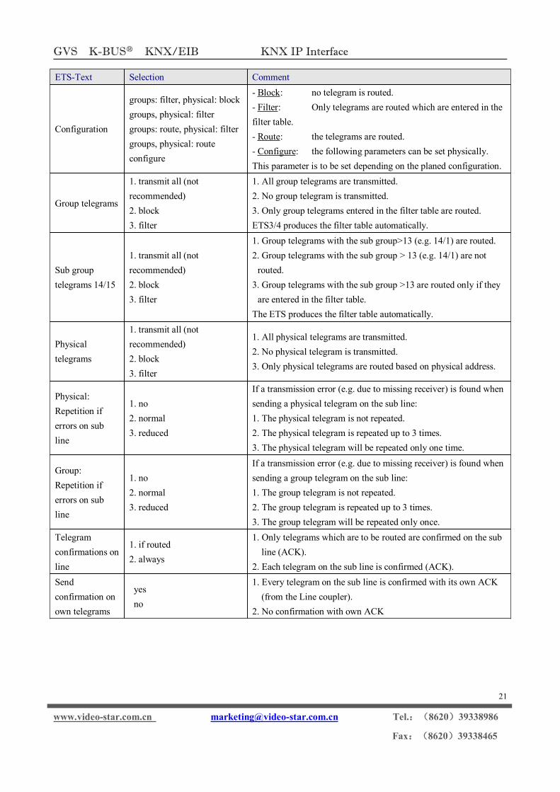
4.6 Sub Line
Fig. 4.7: Sub line
Note: If the parameter “Send confirmation on own telegrams” is set to “yes”, with sending any ownrouted telegram the MECip will systematically send an ACK.
GVS K-BUS○R KNX/EIB KNX IP Interface
21
www.video-star.com.cn [email protected] Tel.:(8620)39338986
Fax:(8620)39338465
ETS-Text Selection Comment
Configuration
groups: filter, physical: blockgroups, physical: filtergroups: route, physical: filtergroups, physical: routeconfigure
- Block: no telegram is routed.- Filter: Only telegrams are routed which are entered in thefilter table.- Route: the telegrams are routed.- Configure: the following parameters can be set physically.This parameter is to be set depending on the planed configuration.
Group telegrams
1. transmit all (notrecommended)2. block3. filter
1. All group telegrams are transmitted.2. No group telegram is transmitted.3. Only group telegrams entered in the filter table are routed.ETS3/4 produces the filter table automatically.
Sub grouptelegrams 14/15
1. transmit all (notrecommended)2. block3. filter
1. Group telegrams with the sub group>13 (e.g. 14/1) are routed.2. Group telegrams with the sub group > 13 (e.g. 14/1) are notrouted.
3. Group telegrams with the sub group >13 are routed only if theyare entered in the filter table.
The ETS produces the filter table automatically.
Physicaltelegrams
1. transmit all (notrecommended)2. block3. filter
1. All physical telegrams are transmitted.2. No physical telegram is transmitted.3. Only physical telegrams are routed based on physical address.
Physical:Repetition iferrors on subline
1. no2. normal3. reduced
If a transmission error (e.g. due to missing receiver) is found whensending a physical telegram on the sub line:1. The physical telegram is not repeated.2. The physical telegram is repeated up to 3 times.3. The physical telegram will be repeated only one time.
Group:Repetition iferrors on subline
1. no2. normal3. reduced
If a transmission error (e.g. due to missing receiver) is found whensending a group telegram on the sub line:1. The group telegram is not repeated.2. The group telegram is repeated up to 3 times.3. The group telegram will be repeated only once.
Telegramconfirmations online
1. if routed2. always
1. Only telegrams which are to be routed are confirmed on the subline (ACK).
2. Each telegram on the sub line is confirmed (ACK).Sendconfirmation onown telegrams
yesno
1. Every telegram on the sub line is confirmed with its own ACK(from the Line coupler).
2. No confirmation with own ACK

GVS K-BUS○R KNX/EIB KNX IP Interface
22
www.video-star.com.cn [email protected] Tel.:(8620)39338986
Fax:(8620)39338465
5. State of Delivery
The IP Router is delivered with the following default factory settings:
Physical address 15.15.0
Physical address for tunneling connections
15.15.241
15.15.242
15.15.243
15.15.244
IP configuration
IP address assignment DHCP/Auto IP
IP routing multicast address 224.0.23.12
Main Line (IP to KNX)
Group telegrams 0-13 Filter
Main group telegrams 14/15 Filter
Physical telegrams Filter
Sub Line (KNX to IP)
Group telegrams 0-13 Filter
Main group telegrams14/15 Filter
Physical telegrams Filter
Physical: Repetition if errors on sub line normal
Group: Repetition if errors on sub line normal
Telegram confirmations on line if routed
Send confirmation on own telegrams no