Embed Size (px)
Citation preview
HYPERSONIC AERODYNAMIC CHARACTERISTICS OF A PROPOSED SINGLE-STAGE-TO-ORJ3IT VEHICLE
K. James Weilmuenster" P. A. Gnoffo," F. A. Greene,* C . J. Riley,? and H. H. Hamilton 11"
NASA Langley Research Center Hampton, VA
S. J. Alters Lockheed Engineering Sciences Co.
Hampton, VA
Abstract
The hypersonic aerodynamic characteristics of a winged body concept representing a candidate single- stage-to-orbit vehicle which features wing tip fin controllers and elevon/bodyflap control surfa'Fs are predicted at points along a nominal trajectory for Mach numbers from 5 to 27 and angles of attack from 19 to 32 degrees. Predictions are derived from surface properties based on flow solvers for inviscid and viscous, laminar flows acting as a perfect gas, as a gas in chemical equilibrium and as a gas in chemical non- equilibrium. At a Mach number of 22, the lateral aerodynamic characteristics of the vehicle are determined based on an inviscid analysis at side slip angles of 2 and 4 degrees and 32 degrees angle of attack; a viscous analysis was carried out to determine the effect of gas chemistry model on surface pressure and to determine the incremental aerodynamics for control surface deflections. The results show that the longitudinal pitch characteristics of the baseline configuration, i.e., zero control surface deflections, are significantly altered by real gas chemistry at angles of attack greater than 30 degrees and Mach numbers greater than 9; and, that aerodynamics derived from inviscid solutions are of sufficient accuracy for preliminary analysis. Also, it is shown that a Mach number of 22, the choice of gas chemistry model has a largeimpact on surface pressure levels at highly localizedregions on the vehicle and
*Senior Research Engineer, Aerothermodynamics Branch, Research Technology Group, Associate Fellow, AIAA
?Research Engineer, Aerothermodynamics Branch, Research Technology Group, Member AIAA
*Research Engineer, Aerothermodynamics Branch, Research Technology Group
§Research Engineer, Member AIAA
Copyright 0 by the American Institute of Aeronautics and Astronautics, Inc. No copyright is asserted in the United States under Title 17, U. S. Code. The U. S . Government has a royalty-free license to exercise all rights under the copyright claimed herein for Government Purposes. All other rights are reserved by the copyright owner.
that the vehicle can be trimmed at control surface deflections less than 11 degrees.
Nomenclature
= reference area, 421.1 1 ft2 = wing span, 566 in. = axial force coefficient, F A / S,fq, = rolling moment coefficient, Ml / bSrefqm = pitching-moment coefficient, Mo / CSrefqm = yawing moment coefficient, M, / bSrefqm = normal force coefficient, F, / Srefqm = side force coefficient, FY / S,fq, = reference chord length, 2227.0 in.
S b CA C1 Cm C, C, Cy c FA = axial force, lbf FN = normal force, lbf FY = side force, lbf M = Mach number M1 = rolling moment, ft-lbf M, = yawing moment, ft-lbf Mo = pitching moment, ft-lbf P = pressure, Ibf/ft2 q = dynamic pressure, lbf/ft2 Re = unit Reynolds numbers per foot V = velocity, ft/sec x,y,z = Cartesian coordinates, local coordinate
a = angle of attack, deg p = side slip angle, deg y = specific heat ratio A = difference 6 = deflection angle, deg p = density, slugs/ft3
-
system, in.
Subscripts
c.g. = center of gravity ref = reference value S = post shock condition trim = trim angle w = wall M = freestream
1
American Institute of Aeronautics and Astronautics

Introduction Geometry and Grids
As the Space Shuttle fleet ages, NASA is laying the ground work for the next generation space transportation system. In its initial stages, this effort concentrated on identifying the technologies and launch strategies that would lead to an efficient and cost effective space transportation system for the twenty-first century. The effort culminated in a NASA, DOD, DOT interagency access to space study, Ref. 1, that identified the single-stage-to-orbit (SSTO) rocket powered launch concept as the most likely to meet the agencies' goals. In response to these findings, the Vehicle Analysis Branch at Langley Research Center established a SSTO configuration for a thorough systems analysis. In the area of aerothermodynamics, these analyses are based on approximate engineering codes and the results from testing in ground based facilities. Experience with the Shuttle Orbiter, Ref. 2, showed that, in the high hypersonic flight regime (M, > lo), reliance on these techniques alone lead to significant differences between the predicted and actual flight aerodynamics of the vehicle. For the first Orbiter flight, STS-1, an unexpected increase in the nose up pitching moment in the hypersonic flight regime required a bodyflap deflection twice that indicated by the preflight data book in order to trim the vehicle. Navier-Stokes computations for the Shuttle Orbiter, in Ref. 2, at similar flow conditions and attitudes being considered herein showed that the impact of shear stress on CN and C, was negligible while it accounted for 25 percent of CA. This work also showed that the discrepancies in the preflight data book and in flight pitching moment were due to the aerodynamics of the baseline Orbiter, i s . , zero control surface deflections; and, that these differences were primarily due to the effect of reacting gas chemistry on the surface pressure field on the aft, Le., expansion portion of the windward surface. The control surfaces were also affected by real gas chemistry as well as viscous effects. The only impact of this flow was on the control authority available to overcome the nose up pitching moment of the baseline vehicle. Given the above observations, it was decided to predict the longitudinal and lateral aerodynamic characteristics of the vehicle using a Euler flow solver. In addition, Navier-Stokes solutions were generated at selected points to back up the results from the Euler solutions and to determine con,yol surface effectiveness which is a viscous dominated problem. Also, flow chemistry effects are included in all computations. Where appropriate, comparisons have been made with predictions from an engineering approximation code. This paper details the techniques used and the results of these predictions.
The coordinate system in which the geometries and grids are described along with the convention for the aerodynamic coefficients is shown in Fig. 1. The full vehicle geometry is shown in Fig. 2. The surface was constructed in the PRO ENGINEERING solid modeling software and transferred through a standard IGES format to the ICEM surface modeling system which was used to create the 161 x 129 surface grid shown in Fig. 3 where every other grid point has been removed for visual clarity. The volume grids were created using the GRIDGEN, Ref. 3 , software to define the volume outer boundary and the 3DMAGGS code, Ref. 4, to define the internal volume grid. The grids for the Euler computations have 33 points between the wall and the outer boundary; see Fig. 4. The viscous grids have 65 points between the wall and outer boundary. The grid resolution studies described in Ref. 5 indicate that these number of points will produce solutions of high accuracy.
The geometry shown in Fig. 5 is used for the control deflection studies. For the purposes of this study, the elevons and body flap were assumed to share the same hinge line and, at hypersonic speeds, they are slaved together. The gap between the outboard edge of the elevon and the lower surface of the wing was modeled with a solid surface. In Ref. 2, a similar approximation was shown to produce differences in the aerodynamics for the Shuttle Orbiter of less than 1 percent.
Computational Techniaues
Flowfield Solutions
Code: The formulation of the Langley Upwind Relaxation Algorithm (LAURA) is presented in detail in Refs. 6-8. The LAURA code can compute inviscid or viscous solutions for perfect gas flows and reacting gas flows in either an equilibrium or non-equilibrium state. The inviscid flux is constructed using Roe's flux- difference-splitting, Ref. 9, and Harten's, Ref. 10, entropy fix with second order corrections based on Yee's symmetric total variation diminishing scheme, Ref. 11.
Chemistry: Tannehill's, Ref. 12, curve fits are used for the thermodynamic properties of equilibrium air. A 7-species chemical reaction model, Ref. 13, is used for the reacting gas computations. The species N, 0, N2, 02, NO, NO+, and e are accounted for in the model.
2
American Institute of Aeronautics and Astronautics

Boundarv Conditions: For the Euler computations, the surface tangency condition is applied at the wall. The usual no-slip condition is imposed at the wall for the viscous computations. Freestream conditions are set at points on the outer boundary of the computational domain; and, the exit plane is set such that the inviscid outflow is supersonic.
Thermal Surface Model: For this analysis, the thermal protection system for the vehicle is taken to be the same as that for the Shuttle Orbiter. The implementation of the catalytic wall boundary condition, which is only implemented in the viscous solutions, is based on the work of Thompson, Ref. 14. This approach has been shown in both Refs. 13 and 14 to produce results which are in good agreement with Orbiter flight data.
Wall TemDerature: The Euler solutions are independent of the wall temperature. For the viscous solutions, the results presented herein account for a variable wall temperature which is determined as part of the solution and is based on the radiation equilibrium temperature at the wall, Ref. 13.
Envineering Apvroximation
The Aerodynamic Preliminary Analysis System, or APAS, is an interactive computer program that was developed to estimate the aerodynamic characteristics of aerospace vehicles, Ref. 15. As the name implies, its intent is as a preliminary evaluation tool used to obtain quick estimations of configuration aerodynamics. Computationally, APAS run times are on the order of minutes, so that the aerodynamic characteristics of a particular configuration may be estimated throughout the flight regime in a matter of hours. Its intent is not to replace wind tunnel or more rigorous analytical results, but rather to provide an efficient means of estimating vehicle aerodynamic characteristics in the conceptual and preliminary design stages.
Solution Technique
A multiblock solution strategy is applied in two stages. The first stage may be regarded as a space marching solution, like the Parabolized-Navier-Stokes (PNS) methods, except that three-dimensional data blocks are employed rather than two-dimensional data planes. The second stage is a conventional, global relaxation which uses the first stage solution as an
initial condition. The advantages of the three- dimensional block-marching over two-dimensional block-marching are that solution robustness is not sacrificed when employing second-order discretization in the stream-wise direction and embedded subsonic pockets and shock-boundary layer interactions are easily computed-provided that the outflow boundary of the sub-domain is intelligently chosen. The sub-domain boundaries are easily tailored to the physics of a given application. A detailed description of this solution technique can be found in Ref. 13.
ComDutational Points
A plot of Mach number and angle-of-attack as a function of time from entry interface for the nominal vehicle trajectory is shown in Fig. 6. Based on guidance and control and thermal loads requirements, eight points on the trajectory were selected for analysis. These points and the corresponding freestream conditions are given in Table 1. Although surface heating results are not discussed in this paper, thermal loads concerns were taken into account when selecting the computational points since the Euler solutions can be coupled with axisymmetric analog techniques to predict wind side surface heating levels. Also, the viscous solutions have sufficient grid resolution to provide heating results. As an example, CFD point 7 corresponds to peak heating for the entry trajectory. Also, the normal shock density ratio, ps/p~, is given in the table. This parameter serves as an indication of the level of real gas effects, i.e., as M, -+ 00, psIp1 + 6.0 for a gas with a y = 1.4. Also, at CFD point 7, an inviscid analysis of vehicle lateral aerodynamics at p = 0,2 and 4 degrees and a viscous analysis of aerodynamic increments due to control surface deflections of 10 and 20 degrees are carried out. For all computations presented in this paper, the base pressure is taken to be P, and all viscous computations are laminar.
Results
First, the predicted longitudinal aerodynamics of the baseline configuration along the nominal trajectory are presented. For all computations, the base pressure is taken as the freestream pressure. All viscous solutions are for laminar flow. Then a more detailed assessment of the aerodynamics is presented for the CFD point 7 on the trajectory. The assessment includes variations in side slip, angle-of-attack, and control surface deflections. Finally, results are presented for the surface pressures, and effects of gas chemistry.
3
American Institute of Aeronautics and Astronautics
Longitudinal Aerodvnamics: The longitudinal aerodynamics for the baseline (e.g., zero control surface deflections) vehicle are shown in Fig. 7(a-c). The reader is cautioned that these are C, - M, plots and that the angle of attack varies with M, per Table 1. For M, of 10.9 and above, the angle of attack is fixed at 32 deg. Figure 7(a) shows the pitching moment as a function of M,. This figure shows the moments derived from the inviscid solutions (solid symbols) for three gas chemistries: perfect, equilibrium, and non- equilibrium (which is represented by one and two temperature solutions). The perfect-gas solutions were not extended past M, = 14 because it was shown in Ref. 2 that above M, = 10 the effect of Mach number on pitching moment for the Shuttle Orbiter at a = 40" was less than 5 percent. As expected, the difference between the equilibriudnon-equilibrium and perfect-gas derived moments increases with M,. At the highest Mach numbers, the difference between equilibrium and non-equilibrium results are small when compared to the difference between the reacting gas and perfect gas values. The difference in the reacting gas results is due to the dependency of the surface pressure and shock layer thickness on the gas chemistry model. This effect will be demonstrated in a later section of this paper. The reacting gas solutions were run at a M, below 10 to ensure that the reacting gas codes would reproduce perfect-gas results at the appropriate conditions. It is obvious that the equilibrium values of C, are approaching the perfect-gas value at M, = 7. The non- equilibrium values have the right trend but, at the lower Mach numbers, the equations governing the chemical reactions become so stiff that it is not practical to run those cases. Also included on this plot are equilibrium and a non-equilibrium viscous solutions at
= 21.89. The viscous solutions are in good agreement with one another and are bracketed by the Euler solutions. Thus, for this case, using the Euler equations to determine pitching moment characteristics of the baseline configuration appears to be a reasonable approach. In addition, the moment coefficients generated by the engineering code APAS are included for comparison. These perfect-gas values form a curve that is similar to that for the perfect-gas CFD data but at a level that is approximately 1.5 times greater than the CFD results. Figure 7(b) shows the normal force coefficient as a function of M,. All of the CFD solutions essentially collapse to a single curve. Thus, neither reacting gas chemistry or shear stress have any significant impact on the normal force on the vehicle. This is consistent with the results reported in Ref. 2 for Shuttle Orbiter computations at both wind tunnel and flight conditions. As demonstrated in Ref. 2, the large
differences in pitching moment are not reflected in the normal force because they are due to small differences in the distribution of surface pressure. As with the plot of pitching moment, the values of CN generated by APAS are consistently higher (20 percent) than the CFD values. Figure 7(c) shows the axial force vs. M, curve. Here, the Euler and APAS data differ by as much as 40 percent at the lowest Mach numbers. As the two viscous solutions indicate, at this point on the trajectory, the inviscid approximation under predicts the axial force by 30 to 40 percent. The difference in the aerodynamic coefficients for the viscous computations based on different chemistry models at the same freestream conditions can be attributed to different viscosity formulations and thermal boundary conditions at the wall.
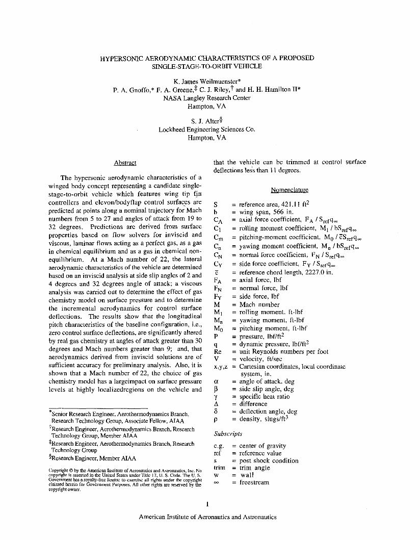
Side Force: Non-equilibrium inviscid solutions were obtained at CFD point 7 for side slip angles of 2 and 4 degrees. The vehicle forces and moments derived from these solut ions are shown in Figs. 8(a-f) where the results have been reflected for negative values of beta. The variation of the longitudinal coefficients C,, CN, and CA are plotted in Figs. 8(a-c). As the plots show, these forces and moments are only slightly affected by side slip angle. The side force coefficients are plotted in Figs. 8(d-f). The yawing moment plot, Fig. 8(d), represents a vehicle instability. The roll moment and side force plots, Figs. 8(e and f), are nominal in nature and do not represent any stability problems for the vehicle.
Angle of Attack Effects: To demonstrate the effect of angle of attack on the baseline configuration aerodynamics, viscous, non-equilibrium solutions were generated for angles of attack of 28, 32, and 36 degrees at CFD point 7 conditions. The predicted aerodynamics based on these solutions are shown along with those predicted by the APAS engineering approximation code in Figs. 9(a-f). In general, the trends in the APAS and CFD data are consistent while the magnitude of the individual coefficients are not in agreement. As expected, based on the results shown in Fig. 7, APAS underpredicts the CFD CA, Fig. 9(a), by 30 percent and overpredicts CN, Fig. 9(b), by 20 percent although the incremental change with angle of attack is nearly the same for both sets of data. Both the APAS and CFD data show a maximum in C,, Fig 9(c), but not at the same angle of attack. CL, CD, and L/D, Figs. 9(d-f), are all functions of CA and CN and exhibit the same behavior as those parameters. The CFD predictions indicate an L/D that is lower than that predicted by APAS but less sensitive to changes in angle of attack.
4
American Institute of Aeronautics and Astronautics

Contro l Sur face Increments : Since flow separation in front of a deflected control surface has a major impact on the aerodynamic performance of that surface, this investigation was based on viscous computations. The computations were made at the CFD point 7 for control surface deflections of 10 and 20 degrees and angles of attack of 28, 32, and 36 degrees. The solutions used in the angle of attack analysis served as a basis for these calculations. The upstream boundary of the computational domain was taken to be a plane of data from these solutions that was located at a point far enough upstream of the control surface hinge line to be out of the influence of the separation bubble. This resulted in a grid one third the size of the original grid with a corresponding reduction in the computational resources for each solution.
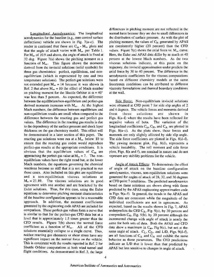
The predicted incremental aerodynamics as a function of control surface deflection and angle of attack are shown in Figs. 10(a-c). For all cases, the magnitude of the increments increases with angle of attack. Also, the increments are highly non-linear in control surface deflection. For example, the control authority provided by a 20 degree deflection is 3 to 4 times greater than that delivered by the control surface deflected 10 degrees. Figure 11 shows the control surface deflection required to trim the vehicle at these freestream conditions as a function of angle of attack. As sized for this study, the control surfaces provide ample authority to trim the vehicle hypersonicly using moderate control surface deflection angles.
Surface Pressures: Figure 12 shows vehicle surface pressure contours at CFD point 7 for a viscous, non-equilibrium flow. Pressures over the windward surface of the vehicle vary over a narrow range with small spatial gradients except at the stagnation point, at the winglbody juncture, and at the wing and tip fin leading edges while pressures on the leeside of the vehicle are one to three orders of magnitude less than those found on the wind surface. Surface pressures are tied directly to the topology of the shock envelope surrounding the vehicle which is a function of freestream conditions and vehicle geometry. Figure 13 shows the shock envelope that corresponds to the surface pressures shown in Fig. 12. In Figure 13 are indicated the bow shock created by the forebody of the vehicle, the wing shock created by the wing protruding into the freestream, and the tip fin shock created by the tip fin protruding into the freestream. The high pressure region on the wing near the wing body juncture is a result of the winghody shock interaction while pressure on the leading edge of the tip fin is influenced by the tip finlwing shock interaction.
The change in shock envelope topology as the freestream changes can have a profound effect on the magnitude and distribution of surface pressures. For example, as the angle of attack increases, the tip fin will move inside the wing shock which will radically alter the pressure distribution on the leading edge of the tip fin. The effect of changing angle of attack on surface pressure is shown in Figs. 14(a-c) for viscous, non-equilibrium solutions at CFD point 7. Figure 14(a) shows pressures on the centerline increasing with angle of attack as the bow shock moves closer to the body. The behavior of the pressure at z = 500 and 1600 inches is due to changes in surface curvature induced by blending of the nose and wing sections into the main fuselage. The stagnation point pressures remain almost constant as they are a function of freestream conditions and body radius of curvature at the stagnation point which is virtually unchanged for these three angles of attack. Wing leading edge pressures as a function of angle of attack are shown in Fig. 14(b). The outboard pressure spike moves inboard and decreases in magnitude as the angle of attack increases. The magnitude of the inboard spike can be as much as 20 percent higher than the stagnation pressure. The most dramatic changes in pressure distribution with angle of attack occur along the tip fin leading edge as shown in Fig. 14(c). At a = 28 deg., approximately half of the tip fin protrudes into the freestream which produces the large pressure spike due to the tip fidwing shock interaction. Conversely, at a = 36 deg., the tip fin lies entirely within the wing shock envelope which leads to a reduced and smoothly varying pressure level along the leading edge.
Chemistrv Model Effects: The effect of chemistry model on surface pressures at a = 32 deg and M, = 21.89 is shown in Figs. 15(a-c). As seen in Fig. 15(a), the chemistry model has little effect on the windward centerline pressure distribution. This indicates that outside of the immediate stagnation region, the flow is at or very near local equilibrium. This is not the case for the wing and tip fin leading edges, Figs. 15(b-c). The use of an equilibrium chemistry model at this Mach number produces a shock that lies closer to the vehicle on the wind side than would a shock based on non-equilibrium chemistry. This then changes the location of the bowlwingltip fin shock interactions, which, along with the different flow chemistries, leads to the pressure distributions shown in Figs. 15(b-c). The example shown here represents a worst case scenario. As the Mach number decreases, the effect of chemistry model selection on surface pressure distributions will diminish. These different pressure
5
American Institute of Aeronautics and Astronautics

distributions, however, appear to have little effect on the vehicle aerodynamics as pointed out in the discussion of Fig. 7. As shown in Fig. 12, the high pressure regions associated with the shock interactions and the pressure distributions in Figs. 15(b-c) are confined to a small area near the wingbody juncture and the tip fin leading edge. Since the area over which these pressure differences occur represents a very small fraction of the total surface area of the vehicle, they will have little impact on the total integrated force over the entire vehicle. Overall, the equilibrium calculations do a good job of predicting vehicle aerodynamics with a reasonable accuracy in the hypersonic flight regime. Since equilibrium calculations require approximately 50 percent less computer resources per solution than the non-equilibrium calculations, they represent an attractive tool for preliminary aerodynamic analysis. On the other hand, if localized loads are the desired product of the calculation, then care must be taken to choose the appropriate flow chemistry model.
Conclusions
The aerodynamic characteristics of a proposed single-stage-to-orbit vehicle have been predicted at points along a nominal trajectory in the hypersonic flight regime. For the baseline configuration, i.e., no control surface deflections, these predictions indicate significant real gas effects on pitching moment at Mach numbers greater than 10; and that the aerodynamics based on CFD analysis and those based on an engineering approximation can differ by as much as 40 percent for CA and C, and 20 percent for CN. A comparison of baseline vehicle aerodynamics at M = 2 1.89 based on inviscid and viscous, non-equilibrium flow solutions show, that at this condition, the inviscid technique is sufficiently accurate to predict the aerodynamics of the vehicle for preliminary analysis. The predicted lateral aerodynamics for the baseline vehicle at M = 21.89 and side slip angles of 0, 2, and 4 degrees indicate there are no lateral stability issues at this condition. Both a CFD and an engineering approximation angle of attack analysis of the baseline vehicle aerodynamics was carried out at M = 21.89. This analysis revealed that although the magnitude of the coefficients associated with each technique were quite different, the trends in each data set were similar. Also, at this same Mach number, a viscous non- equilibrium flow analysis of the vehicle with deflected control surfaces shows that hypersonicly, the vehicle can be trimmed at control surface deflections less than 11 degrees. Further calculations show that both choice of chemistry model (equilibrium or non-equilibrium)
and changes in angle of attack of f 4 degrees will produce large changes in pressure level at highly localized regions of the vehicle due to changes in shock envelope topology and interactions.
Acknowledmnent
The authors thank Walt Englund of the Vehicle Analysis Branch, Langley Research Center of providing the APAS data base.
References
'Access To Space Study-Summary Report, Office of Space Systems Development, NASA Headquarters, January 1994.
2Weilmuenster, K. J . , Gnoffo, P. A., and Greene, F. A.: "Navier-Stokes Simulations of Orbiter Aerodynamic Characteristics Including Pitch Trim and Bodyflap," Journal of Spacecraft and Rockets, Vol. 31, No. 3, May-June 1994, pp. 355- 366.
3Steinbrenner, J., Chawner, J. and Pouts, C.: "Multiple Block Grid Generation in the Interactive Environment," AIAA Paper 90-1602, June 1990.
4Alter, S. J. and Weilmuenster, K J.: "The Three- Dimensional Multi-Block Advanced Grid Generation System (3DMAGGS), NASA TM-108985, May 1993.
5Weilmuenster, K. J. and Gnoffo, P. A.: "Solution Strategy for Three-Dimensional Configurations at Hypersonic Speeds," Journal of Spacecraft and Rockets, Vol. 30, No. 4, July-August 1993, pp. 385-394.
6Gnoffo, P. A., Gupta, R. N., and Shinn, J.: "Conservation Equations and Physical Models for Hypersonic Air Flows in Thermal and Chemical Nonequilibrium," NASA TP-2867, February 1989.
7Gnoffo, P. A.: "Upwind-Biased, Point-Implicit Relaxation Strategies for Viscous Hypersonic Flows," AIAA Paper 89-1972, June 1989.
*Gnoffo, P. A.: "An Upwind Point Implicit Relaxation Algorithm for Viscous Compressible Perfect-Gas Glows," NASA TP-2953, February 1990.
6
American Institute of Aeronautics and Astronautics

9Roe, P. L.: "Approximate Riemann Solvers, Parameter Vectors, and Difference Schemes," Journal of Computational Phvsics, Vol. 43, 1981, pp. 357- 372.
1 OHarten, A.: "High Resolution Schemes for Hyperbolic Conservation Laws," Journal of Computational Phvsics, Vol. 49, No. 3, 1983, pp. 357-393.
"Yee, H. C.: "On Symmetric and Upwind TVD Schemes," NASA TM-86842, September 1985.
' *S r in ivasan , S . , Tannehi l l , J . C., and Weilmuenster, K. J.: "Simplified Curve Fits for the Thermodynamic Properties of Equilibrium Air," NASA RP 1181, August 1987.
13Gnoff0, P. A., Weilmuenster, K. J., and Alter, S. J.: "Multiblock Analysis for Shuttle Orbiter Re-entry Heating from Mach 24 to Mach 12," Journal of Spacecraft and Rockets, Vol. 31, No. 3, May-June 1994, pp. 367-377.
14Thompson, R. A.: "Comparison of Nonequilibrium Viscous-Shock-Layer Solutions with Shuttle Heating Measurements," Journal of Thermophysics and Heat Transfer, Vol. 4, No. 2, April 1990.
15Bonner, E., Clever, W., and Dunn, K . : "Aerodynamic Preliminary Analysis System 11. Part I - Theory," NASA-CR 165627, 1989.
7
American Institute of Aeronautics and Astronautics

Table 1 Computational Points
CFD Time Density Temp Velocity Mach Point sec kg/m3 K d s e c a, deg no. P2’P 1 &/ft
1 1784 2 1687 3 1597 4 1527 5 1417 6 1258 7 1032 8 410
~
0.006963 0.002678 0.001007 0.0006633 0.0003534 0.0001997 0.0000717 0.000023
240.03 258.07 270.65 264.40 249.95 237.53 216.78 201.37
1550.9 2259.7 2973.6 3551.4 4439.5 5492.5 6461.8 7714.8
19.126 24.329 29.47 32.00 32.00 32.00 32.00 32.00
4.993 7.0167 9.016
10.895 14.008 17.777 21.893 27.1 19
5.0 6.61 8.83
10.55 11.12 13.42 16.18 19.02
7 x 10⁶ 6.1 x 10⁵
3 x 10⁵ 2.37 x 10⁵ 1.58 x 10⁵ 7.1 x 10⁴
5.55 x 10⁴ 2.3 x 10⁴
8
American Institute of Aeronautics and Astronautics

Fig. 1. Coordinate systems and aerodynamic convention.
Fig. 4. Single-stage-to-orbit vehicle volume grid.
Fig. 2. Single-stage-to-orbit vehicle surface geometry. Fig. 5. Single-stage-to-orbit vehicle surface definition with control surfaces deflected.
1000 1500 2000 time, sec
Fig. 3. Single-stage-to-orbit vehicle surface grid. Fig. 6. Re-entry trajectory Mach number and angle of attack as a function of time measured from entry interface.
9
American Institute of Aeronautics and Astronautics

0.030 r a variable+~=32'
0' 0.060
0.050
0.020 0.025i m ~
-
0.01 5 t w
1.0
0.8
0.6
0.4
0.2
t f - ~ 1 . 4
-
-
-
-
-
r
0.010
0.005
-+- equilibrium + non-equilibriumll Temp/ inviscid A non-eauilibriuml2 Temp 4 non-equilibriumll TempF~scous D equilibrium - APASAnviscid
0.000 0 5 10 15 20 25 30
N.
0'
1 0.080
0.070 1
0 . 0 4 0 1 ~ " " " ' " " " " " " ' ~ ' ' " " ' ' ~ ~ " ' ' " ~ -4 -3 -2 -1 0 1 2 3 4
li deg.
' G L i b d u m ] inv$cid non-equllibriuml 1 Temp T non-equilibriuml2 Temp
Q nowequillbriuml 1 Temp v,scous D equilibrium - APAS/ Imlscld
0 . 0 ~ ~ " " " ~ ' ~ " ~ ' ~ " " " " ~ ' " " ~
M_
0 5 10 15 20 25 30
7(b) CN
$ equllibrium - APAW lnvbcld
O.1° t 8 0'
"* 0.05 I w a varbbb+ a.32'
0.70 -4 -3 -2 -1 0 1 2 3 4
B, deg.
0.030
E 0.024
0.022 L
-4 -3 -2 -1 0 1 2 3 4
IX deg.
Fig. 7. Single-stage-to-orbit vehicle longitudinal aerodynamics as a function of Mach number along the re-entry trajectory.
Fig. 8. Side force aerodynamics as a function of side slip angle at M, = 21.89 and a = 32 deg. predicted via inviscid non-equilibrium, one temperature flow model.
10
American Institute of Aeronautics and Astronautics
0.090
vu 0.080
0.070
0.060 20 25 30 35 40
a, deg.
-
U A P A S A n v i s C i d . +non-equilibriumMscous
0.01 5
0.10 r
-0.10 -4 -3 -2 -1 0 I 2 3 4
!3, deg.
Fig. 8. (contd.) Side force aerodynamics as a function of side slip angle at M, = 21.89 and a = 32 deg. predicted via inviscid non- equilibrium, one temperature flow model.
I 0.030
0.025 1 \ U APASfinviscid
-<tnon-equilibriudn/viscous t VE
t 0.020
0.015l " ' " ' ' ' 5 1 . . I 20 25 30 35 40
a, deg.
9(c> c, Fig. 9. Comparison of CFD and APAS prediction
of effect of angle of attack on longitudinal aerodynamics at M, = 2 1.89.
11
American Institute of Aeronautics and Astronautics

0'
1.2 -
1.0 - ' U APASAnviscid - -0- non-equilibfiumMscous
20 25 30 35 40 a, deg.
a, *g.
CD
1.8r
3 1.4 1 UAPASSAnviScid
40
1.2 -
1.0 " " " " " " " " ' " I 20 25 30 35
a, deg.
Fig. 9. (contd.) Comparison of CFD and APAS prediction of effect of angle of attack on longitudinal aerodynamics at M, = 21.89.
O . I 2 F
6, deg
0.30 t
--u-- a=28' -$- -32"
0.25 1 0.201 a=360 ///
: -$- -32"
6, deg 6, deg
CN
- a=28' -+- ~ 3 2 " -c- ~ ~ 3 6 '
0 5 10 15 20 6, deg
-0.10 ' ' ' ' ' ' ' ' ' ' ' ' ' ' I ' ' ' ' I
Fig. 10. Incremental longitudinal aerodynamics as a function of control surface deflection and angle of attack at M, = 21.89 for viscous, non-equilibrium flow.
12
American Institute of Aeronautics and Astronautics
1.0 r
0.4
0 8
'*
0.2
11 "i
-
-
7l 6 28 29 30 31 32 33 34 35 36
a, h g
Fig. 1 1. Control surface deflection required for trim at K = 21.89 as a function of angle of attack.
'Pz.97
Fig. 12. Surface pressure contours at M, = 21.89 and a = 28 deg. for viscous non-equilibrium flow.
Tip F
Shock
Fig. 13. Shock envelope topology, M, = 21.89 and a = 28 deg. for viscous non-equilibrium flow.
o . o ~ ' ' " ' " ' " " ' " ' ' ' ' ' ' ' ' ' 1000 1500 2000 2500 1 0 500
z, in.
14(a) Windward centerline distribution
1.2 ,I
0.2 winglbody
0.0 100 200 300 400 500 600 0
z, in.
14(b) Wing leading edge distribution
max tip fin height7
" 1 , ' . ' 1 . \ , -50 0 50 100
x. in.
14(c) Tip fin leading edge distribution
Fig. 14. Surface pressure distributions as a function of angle of attack at M, = 1.89 for viscous, non-equilibrium flow.
13
American Institute of Aeronautics and Astronautics

0.8
0.6
0.5
0.4
n s
-non-equilibrium - - - equilibrium
r
-
-
0.6 ' 0.4
n s
's
0.2
0.1
0.2
-
non-equilibrium equilibrium - _ - _ _
tip fidwing
o . o ~ " ' " " " ' " " " ' " " " ' 0 500 1000 1500 2000 2500 z, in.
15(a) Windward centerline distribution
non-equillbrium _ _ _ equilibrium
1.0 - a s > d h
0.5 -
L
bodylwing juncture
0.0 " " ~ ~ ~ " ~ ' " ' ' ' . ~ ' 0 100 200 300 400 500 600
y, in.
15(b) Wing leading edge distribution
x, in
15(c) Tip fin leading edge distribution
Fig. 15. Effect of flow chemistry model on surface pressure distributions at M, = 21.89 and a = 32 deg.
14
American Institute of Aeronautics and Astronautics

![Презентация PowerPointyust.ru/upload/iblock/2d9/2d9069ced9bb1557676c77cc676ac7ca.pdf · 3 4 i _ j \ h = j Z ` ^ Z g k d h ] h d h ^ _ d k J h k k b c k d h c ... Применяются](https://img.pdfslide.net/doc/110x75/5f41aadf6c2f4305300fcd8d/-3-4-i-j-h-j-z-z-g-k-d-h-h-d-h-d-k-j-h-k-k.jpg)


![Z l e v g h c y l e v g h k l b» - narod.ru · 4 I Введение 1. H k h [ _ g g h k l b « F b o Z c e h \ k d h ] h k _ e v k d h ] h i h k _ e _ g b y» k h k l F b o Z c](https://img.pdfslide.net/doc/110x75/6029f65d6ed21437251aba90/z-l-e-v-g-h-c-y-l-e-v-g-h-k-l-b-narodru-4-i-1-h-k-h-g.jpg)


![ПРАВИЛА доверительного управления …8 ^ h e ] h k j h q g h c d j _ ^ b l h k i h k h [ g h k l b \ u i m k d Z ( h l k m l k l \ b b j _ c l b g ]](https://img.pdfslide.net/doc/110x75/5f3eef6a52c75a04ee3b2519/-oe-f-8-h-e-h-k-j.jpg)


![bonegraft rusça dental katalog · J k c [ h [ f c b ` l h c g e i ] ] c _ h i r m i i \ k [ b ` q c g ` ` m j i k c l m n y l m k n e m n k n c _ [ h h [ z l m k n e m n k [](https://img.pdfslide.net/doc/110x75/5e4035a47d2a7905ba60ca3f/bonegraft-rusa-dental-katalog-j-k-c-h-f-c-b-l-h-c-g-e-i-c-h-i-r-m.jpg)