Embed Size (px)
Citation preview

3
. " K,' j<.7
BASIC DESIGN OF
STIRLING ENGINE
Training in Alternative Energy Technologies
5th Session
February - June 1982
University of Florida School of Mechanical Engineers
Gainesville, Florida
by
Dr. B. Bihari Ghosh, Coordinator - West Bengal, India Eng. Oscar E. Solera - San Jose, Costa Rica Krishna Gautam - Kathmandu, Nepal Eng. U. Htein Lin - Rangoon, Burma Eng. M. Rokon-Ud-Dowla -Dacca, Bangladesh Eng. Jean Baptiste Bwarak'eye

ACKNOWLEDGEMENT
This work is the outcome -f the fifth session of the TAET program,
directed by Erich Farber. Within the limitation of time, the group was able
to establish this task as the encouraging guidance and supervision of Dr.
Pagano, Dr. Bush and Inky Laketek was continuously available. Without the
hard work and "step by step" support of Messers Vann Chesney, Charles
Garretson and Joe Kurinec, this task would never have been completed or even
started.
The group also is deeply indebted to the work of Dianne Wright, Sharon
Loschke, Jackie Smith, Mary Wallace, Melissa Limcangco, Mary Green, Loree
Taylor and other supporting staff who helped one way or another at various
stages of the program to make our stay enjoyable and our learning
meaningful.

TABLE OF CONTENTS
Acknowledgement Page i
Chapter 1 - Introduction 1
Chapter 2 - Literature Survey 3
Chapter 3 - Theory of Stirling Engine 5 Chapter 4 - Design and Approach of 10 KW
Chapter 5 -
Hydrogen Fueled Stirling Engine Potential Use of Stirling Engine
10
24 Chapter 6 - Economic Feasibility
26
BIBLIOGRAPHY 27

Chapter 1
INTRODUCTION
Stirling engines are external combustion heat engines that usually
utilize air or other gases as working fuel. areThey capable of operating
on any source of heat such as sun, wood, coal, or field waste. The Stirling
cycle lends itself to a wide variety of physical forms, and some of these
are sufficiently simple to make effective and strong ways of power genera
tion in developing countries, using any local fuel or solar energy as 'heir
heat source. Some other works had been made in liquid piston water pumps,
free cylinder water pumps, low pressure air engines, diaphram engines, and
cooling machines. Simple liquid piston water Pumps of reasonable efficiency
and reliability are in the late stages of prototype development. Free
cylinder water pumps, in which a free piston Stirling engine is arranged so
that it pumps by direct action of its hermetically sealed cylinder on the
water, are now well proven. Both of these can use solar, solid fuel or
biogas heat sources.
Now there is a new design of Stirling engine for produce I km of shaft
power at 1200 rpm with a slightly pressurized, dry crankcase using perma
nently lubricated bearings. This machine is readily adaptable to biogas or
solid fuels, rice husks, or hagasse and has universal applications as a
result of its rotating shaft power output.
Stirling engines are also beinq developed for cooling tasks, driving
either Rankine cycle compressors or Stirlinq cycle coolers. Both free
piston and rotating shaft machines are being developed for food freezing and

domestic heat pumps, for both heating and cooling. Possibly the simplest
cooling engine is the duplex Stirling, free piston, heat driven heat pump.
This machine contains both the heat engine and heat pump within the same
hermetically sealed pressure enclosure, which is free of lubricants or any
other fluid than the working gas. Applications of the duplex Stirling
engine include food coolers or freezers, refrigerators, portable vaccine
coolers, and living space air conditioning. These machines could probably
best be driven by biogcs, alcohol or other liquid or gaseous fuels, but
could be adapted to operate on solids such as coal, wood, rice husks,
bagasse, etc.
Another emerging technology of importance is the large stationary
Stirling engine, ranging from 100 Kw to several megawatts of power output,
and are under development for stationary power generation and cogeneration
using solid fuels and would be useful for those purposes elsewhere.

Chapter 2
LITERATURE SURVEY
The first British working model of a hot air engine was introduced and
patented by Sir George Cayley and later adopted by Mr. Buckett. This engine
operated on an open cycle and consisted of two vertical pistons directly
connected so as to make the compression stroke of one of the expansion
stroke of the other. This engine was not equipped with a regenerator and
had a thermal efficiency of 8 per cent. The Stirling brothers seem to have
been the first to carry into practice the principle of a cycle heat engine.
Their Stirling engine operated on a closed cycle and introduced a new
feature, regeneration. Stirling made the heated air, which had already done
work, pass through a wire gauge or this metal plates to take up heat from
the gas. The heat momentarily stored is then transferred to the cold air
coming from the cooler. This air then returns to the hot end tn take up
heat again thus completing the cycle. By This method the Stirling brothers
were able to produce a reversible cycle. The actual engines operating
between 3500 and 650 F converted into work only 7 per cent of the heat
supplied. Such an engine rated at 40 hp was used for three years to drive
machinery in a foundry.
Most of the hot air engines which were developed later were based on
the Stirling engine. Robinson built a compact engine with two pistons at
right angles to each other operating on a closed cycle. The engine designed
by British engineer Bailey resembles the Robinson engine. Most of the work
describ,d above was done in England and nothern Europe.
"I

The hot air engines developed up to 1896 were slow, large and unecon
omical; they offered little competition with the newly developed internal
combustion encines and therefore temporarily disappeared from use. In 1946
the reseearch laooratories of N.V. Philips' Glueilampenfabrieken of
Eindhoven, Holland, resumed work on hot air engines using modern concepts
regarding to the air processes, flow resistance, heat transfer and
properties of newly developed materials.
The engines developed by Philips operating on air cycle have two loaded
pistons while the hot and the cold spaces can be either both in one cylinder
or in two separate cylinders (v-construction). Most of the old air engines
had one loaded and one transfer piston. For larger horsepowers, Philips
developed the multi-cylinder air engine in which the nos of hot air cycles
take place simultaneously. Inthis type of engine only one piston is needed
per system and consequerntly no transfer piston is required. All the loaded
pistons act on a common shaft. Fairly efficient engines of this type from
20 to 30 hp have been put into operation by Philips Laboratories.
David R. Gedeon of Sunpower Incorporated, Athens, Ohio, U.S.A.,
discussed the problem of numerical optimization with any computer simulation
capable of modeling a Stirling cycle machine. A number of optimizations
were done on free piston Stirling engines, each of them different from the
others but evolving towards a software package of universal application.
Willia T. Beale of Sunpower Incorporated, Athens, Ohio 45701, U.S.A.,
designed a free cylinder Stirling engine for use as a solar water pump. The
pumping action takes place as a result of the reciprocating motion of the
cyclinder of the sealed free piston engine, this cylinder motion being used
to directly drive a reciprocting water pump.
Chapter 3
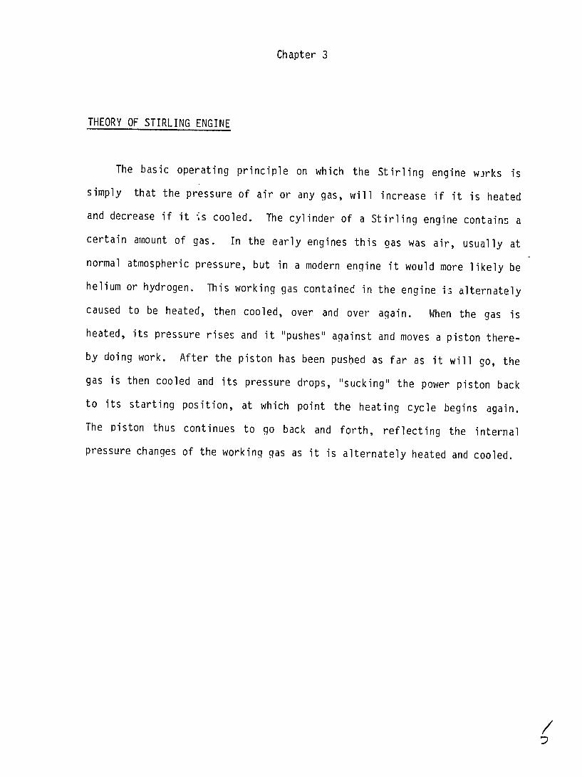
THEORY OF STIRLING ENGINE
The basic operating principle on which the Stirling engine w~rks is
simply that the pressure of air or any gas, will increase if it is heated
and decrease if it Is cooled. The cylinder of a Stirling engine contains a
certain amount of gas. In the early engines this gas was air, usually at
normal atmospheric pressure, but in a modern engine it would more likely be
helium or hydrogen. This working gas contained in the engine is alternately
caused to be heated, then cooled, over and over again. When the gas is
heated, its pressure rises and it "pushes" against and moves a piston there
by doing work. After the piston has been pushed as far as it will go, the
gas is then cooled and its pressure drops, "sucking" the power piston back
to its starting position, at which point the heating cycle begins again.
The piston thus continues to go back and forth, reflecting the internal
pressure changes of the working gas as it is alternately heated and cooled.
1"

The Stirlinq Cycle
(a) Principle of the displacer system
hot pc
l /a."PC 6oo/¢#,
Cold ,4aaC

(b) Thermodynamic cycle
p 3 4
4
V 3
1-2 Isothermal compression at the lower temperature2-3 Heat input at constant volume, raising gas to upper temperature,
increases pressure still further 3-4 Isothermal expansion at upper temperature4-1 Gas cooled to lower temperature at constant volume

(c) Diaqram of the cycle
As
4~ 2t

7tk -Z

-----
-----
Chapter 4
Design approach of 10 kW hydrogen fueled Stirling engine.
Design Conditions
3Volume of hydrogen gas = 100 cmInitial pressure = 100 atm i.e. 10M Pa Compression ratio = 2 Tc = cold side temperature = 270 C
° = 300 K Th = hot side temperature = 6270 C
= 9000 K
3
'3
Stirling cycle, no dead volume, isothermal compression and expansion
Stirling cycle, 33% dead volume, isothermlI c:)mpressicn and expansion

PV = 100 x 105 N/M2 x 100 x 10- 6 m3 = 1000 Joules
PdV 1dW = = PV dVV 1000 dVV, v 50
W 1000 In (I-) = -693.14 Joules
-ve means work is supplied by perfect gas laws
PV mRT= m T or PV =NRTC
where 2 P = gas pressure in N/M2 or M Pa P = gas pressure n N/M 3o MPa V = gas volume, m or cm n = Nos. of moles of hydrogenR = Universal gas constant = 8.134 Joule/K.mal
Tc = cold side temperature, 'K
100 x 105 N/r2 x m3100 x 10- 6 = n x 8.314 x 300
n - 1000 10 == 0.4009 moles8.134 x 300 8.134 x 3
dW = PdV = PVdV V dVV 2 900
i.W = NRTC f - =-NRTc In (vT) = -0.4 x 8.314 x 300 in ( 693.14 Joules
Gas is heated from 3000 K to 900' K Let us assume 100% regenerative efficiency
Thus q(r) = Ncv (Th - Tc)
cv = heat capacity of hydrogen at constant volume 21.030 J/K.mal
hence q (r)= 0.400o x 21.030 x (900 - 300) = 5059 Joule
Process 1-2 P V2V1 P2
T1 T2
P1 Vl = P2 V2 or P - V1 -100 x 105 x 1002 2 x 10⁷ N/M2 1 , V2 50 2x1 /
3 = 50 cm= V3V2
P3 V3 = RT 3 oP3 - V3 50 x 10- 6 =60x1 N 2SNRThoNR To3 _ 0.4009 x 8.314 x 900 60 6
VIoU6 7 i;oJe
W(,t ) = NR Th In V- 0.4009 x 8.314 x 900 x In 1UO 207, Jo..les V2A

1. e
-Vz
The net work generated per cycle is Wnet = W + W(out ) -693.14 + 2079.4
1386.3 Joules
W(net) 1386.3_ = 0.6667 cycle (in) 2079.4
-NR Tc ln + NR Th In --
In general the efficiency is nl W(in) +W(out) Vq(i n) NR Th In v_1
carnot =Th - Tc 9w - 300 0.667Th 900

Stirling cycle, zero dead volume, imperfect regeneration.
TR -eTc
Regeneration efficiency : R T - Tc h Tc
T = temperature of regenerator,
Duri-g heat transfer the heat from the regenerator = q(r) = nc v (TR - TC) and
the heat from the has heater is q(h) = nc (T - TR)v h

Vl V,_
(R (imperfect) - Wnel-Qipreti--n-) NR TH In V2 NRTc in V2
NR TH1 n V-- + N Cv (TH - TR)
TH - Tc
Cv (TH- TR) H R V1
In V
Now nR = TR -T c
TH Tc
-T H T TRcTc or T - nR = HT T-
TH- TR
or TH TTR =(l-qR) (TH TTC)
TH TTc
ncycle TH + Cv (TH - Tc)(l - Y
1 Vl
n V2
T H -T c
If R 11 cycie reduces to H C carnot efficiency
substituting the numerical values
900 - 300 cycle 900 + 21.030 x (900 - 300) (I - nR)
8.314 1n 100n50

600
900 + 2189.5 (1 -R)
.e
.4
.3
"2.
•. .2 .3 4 6 . .,
Effect of Regenerative Effectiveness on efficiency

Rallis derived the formula for the efficiency of a Stirling Engine with no dead volume but imperfect regeneration.
n cycle= - l)(t - I) In r ( -yR ) (t - 1) + t (Y - I In r
where y = cp/cv, t - TH c
n
r v1r- v2
cycle =
If n'R = 1T
(y - l)(t 1) 1n r t y- I n r
n cv
TH
Tc
(
cv
TH
T)c
V
nVn=V2
VI
n V2
TH - Tc
T4 TH/T
TH
TH H
Tc
He dervied also a formula for work
W AVXP 1 r (t
(r-1) n 1)
r
V1 TH
where AV = (V1 - V2) , r V t
or or W
AVXP1 =
V V1 TH
2 Tc -
V1
V V 2)I
V1
16

or W = P1 x (V1 - V) ) nH
2 c 2 V1
(., -1) V2
Substituting the numerical values
- 6W50 x 10 x 10 7 x 2 (3-00 -I) x In2(2 -1In = 1386.3 Joules as before.
Stirling cycle, variable dead volume, perfect or imperfect regeneration.
The addition of dead volume which is present in any real engine decreases the work available per cycle. Assume that the annulus between displacer and cylinderwall has some per centage of dead volume. The gas contained in this annulus is
0
where V = total volume of annulus
dV = Adx = differential volume of the annulus CA = flow area of annulus x = distance along annulus X = total length of annulus
Let Tx = Ax + c, when x = o
Tx = TH = C
when x = X T - TH T - T
Tc -Ax + c = Ax + TH or A c x H c x+TH
substituting the value of Tx in equation P dV
-tx
and integrating, we have
PV In (TH/Tr) PV PV R TH Tc R(T - T )/In(H R
c
TRwher HT = effective gas
In (-)
temperature of the regenerator dead volume Thus when TH = 900'K and Tc = 300 0K
T = 900-300 = 546.1 0KR 00

NowTH + Tc - 900 + 300 600K 2 2 - 540.1K
Hence it car, be assumed TR _ TH + Tc
2
If P be the average pressure for expansion
n = R [VH + VR - 30 x 106 1100 5 R [ -R]- 8.314 9-0 + 5461 = 0.7313 mol
The equation for the gas expansion is
p " NR - 0.7313 x 8.314 - A where A = 5472 VH+ VR VHP 50 VH + B B = 82.4 TH TR 900 540.1
3the work output by expanding from VH1 = 50 cm to VH2 = 100 cm3
VH2 VH2 W(out) = f P dVH = f A dVH
VHI VH1 VH + B
VH2 + B l0+8.
= A In (VH1 + B) = 5472 In (1OO + 82.4 ) = 1753 Joule
the equation for gas compression is
NR 0.7313 x 8.314 C C = 1824.02 Vc VR = Vc 50 Vc + D whereD 27.4
Tc T R 300 546.1
hence: Vc2 + D 50 + 27.4 W(in) = C In (V-cI + D = 1824.02 In 1I00 + 27.4- = 908.37 Joule
Therefore the net work is
W (-net) = W (-out) + W (,in)
= 1753.08 - 908.37
= 844.71 joules

N
Ideal efficiency of Stirling engine 0.607 (with perfect regeneration)
None with imperfect regeneration of 70% regeneration efficiency, q of the output or Input output 10 25 kWengine 0.4 = input 0.4 0.4

i I
MEP- net work 844.71 844.71 N/m2 16.89 x 10⁶ N/m2 16.89 MPaV1 -V2 (100 - 50) - 50 N/rn = 1vi 50 x10
work done = MEP x stroke volume BHP = work done -MEP x stroke volume x N
time w where N is R.P.M.
Let LID 1 where L = stroke length of power piston B bore of power piston
Now BHP= MEP x Vs x N _PLANPLAND_PP xLx__._D Px L3 xN
2 2 2 2 2

Substituting the values of P, L and N in this equation:
16.89 x 10⁶ x P/4 x L3 x 10-6 x 1000 60 x 2 x1000 = 10
L3or _ 10x cm360 x 2 x 4 = 91 or L = D 4.5 cm = 4.5 cm
Stroke of power piston = 4.5 cm Diameter of power piston = 4.5 cm
Compression ratio = displacer stroke volume + piston stroke volumedisplacer stroke volume
=y + piston stroke volume
y
where Y = displacer stroke volume
L2 L3piston stroke volume = P/4 x L = f Tr/4 4-x (4.5)3 71.5 cm3
Then Y+ 71.5 = 2 or Y + 71.5 = 2Y or Y =71.5
Hence Displacer stroke = 4.2 cm Diameter = 4.2 cm
YAP
'.-. E -f I-
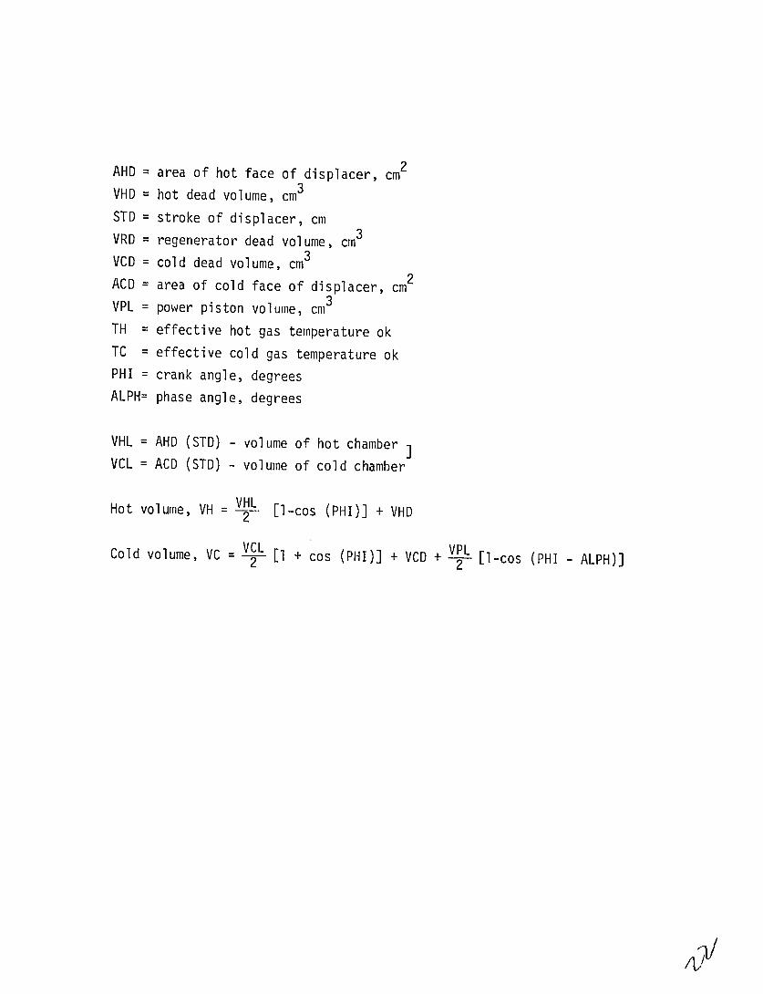
AHD = area of hot face of displacer, cm2
VHD = hot dead volume, cm3
STD = stroke of displacer, cm
VRD = regenerator dead volume, cm3
VCD = cold dead volume, cm3
ACD = area of cold face of displacer, cm2
VPL = power piston volume, cm3
TH = effective hot gas temperature ok TC = effective cold gas temperature ok
PHI = crank angle, degrees
ALPH= phase angle, degrees
VHL = AHD (STD) - volume of hot chamber VCL = ACD (STD) - volume of cold chamber
Hot volume, VH = .-- El-cos (PHI)] + VHD
Cold volume, VC = - [I + cos (.PHI)] + VCD + V- [l-cos (PHI - ALPH)]

CZ)
~VAD
-J
...... P,

Chapter 5
Potential use of Stirling engines.
Commercial production stirling enginesof have not yet started but
appears to be imminent for several uses, first of which is water pumping.
Simple liquid piston water pumps of reasonable efficiency and reliability
are in the late stages of prototype development. Free cylinder water pumps,
in which a free piston stirling engine is arranged so that it pumps by
direct action of its hermetically sealed cylinder (premiere enclosure) on
the water are now well proven and may attract investment from manufacturers
if they see a significant commercial market in the near future. Both the
liquid piston and the free cylinder stirling engines can use solar, solid
fuel on biogas heat sources. The machine is readily adapted to biogas or
solid fuels, rice husks or bagasse and has universal application as a result
of its rotating shaft power output. It is quite simple mechanically and can
be designed to be fabricated in shops.
Varieties of Stirling Engines
(a) Low Pressure Air Engines
This type of engine operating at an average pressure of 1.5 bar, speed
of 900 r.p.m. and a piston displacement of about 3 litres was found capable
of about 1KW shaft power. Its design criteria are simplicity,
repairability, low maintenance.

(b) Free Cylinder Engines.
These are extremely simple mechanisms having only a piston, a displacer
and a cylinder which move to produce work. In their simplest form they use
only an annular gap around the displacer to serve the heat exchange and
regenerative function. They are hermetically sealed and can use hydrogen or
helium without danger of leakage.
Free Piston Alternator Engines
These machines can be sealed up to much larger sizes on the order of
looker/cylinder and gauged together to form large stationary power plants
producing power in the megawatt range. They promise long life, low
maintenance and high thermal eficiency while using solid fuels as their heat
source.
In developing countries, simplified designs of the linear alternator
engine could be built to provide electric power for lighting.
Free Piston Stirling Heat Pump
One of the simplest yet most effective arrangements of Stirling
machines is the duplex Stirling heat driven heat pump. This machine exists
at the moment in small sizes and low temperature (-70 0C) design but is
readily adaptable to refrigeration, for freezing, space cooling and similar
tasks. It requires no higher level of manufacturing skill than the free
cylinder engine or alternator engine and is no more complex mechanically
than the simple free cylinder engine.
U

Chapter 6
Economic Feasibility
Though the capital cost of the Stirling engine is high but as the
conventional fuels are getting exhausted, the Stirling engines will
gradually capture its popularity because these can be used by unconventional
fuels. Especially in the rural areas where the rice husks, coconut shells,
and biomass are abundant, there Stirling engines can be run by these cheap
fuels.

BIBLIOGRAPHY
1. Stirling Engine Design Manual, Report by W.R. Martini, University of Washington, Joint Centre for Graduate Study at NASA, Lewis Research Centre, U.S. Dept. of Energy.
2. Abbot, Charles G., The Sun and the Welfare of Man. Vol. II, Smithsonian Scientific Series, 1934.
3. Brown, A.J., and Marco, S.M., Introduction to Heat Transfer, New York: McGraw-Hill Book Company, Inc., 1957.
4. Donkin, Brian Gas, oil and Air Engines, London: Charles Griffin and Company, Limited, 1911.
5. Obert, E.F., International Combustion Engines. Scranton, Pennsylvania: International Tentbook Company, 1955.
PERIODICALS
1. De Brey, H., Rinia, H., and van Weenen, F.L. Fundamentals for the Development of the Philips Air Engine," Philips Technical Review, 9, No. 4 (1948).
2. Rinia, H., and Du Pre, F.K., "Air Engines" Philips Technical Review, 8, No. 5 (May 1946) pp. 1.29-160.
3. Van Weenen, F.L., "The Construction of the Philips Air Engine," Philips Technical Review, 9, No. 5 (1948).