Embed Size (px)
Citation preview


Medium Duty Body Builder’s Manual
Model: K270/K370
i
Body Builder’s Manual Contents
FIGURES ................................................................................................................................................................. III TABLES .................................................................................................................................................................. V SECTION 1 INTRODUCTION .............................................................................................................................. 1-1 SECTION 2 SAFETY & COMPLIANCE
SAFETY SIGNALS 2-1 SECTION 2 SAFETY & COMPLIANCE .............................................................................................................. 2-2
FEDERAL MOTOR VEHICLE SAFETY STANDARDS COMPLIANCE Incomplete Vehicle Certification .................................................................................................... 2-2 Noise and Emissions Requirements ................................................................................................ 2-3
SECTION 3 DIMENSIONS ABBREVIATIONS 3-1 TURNING RADIUS 3-2 CAB TILT
K270 W/19.5 Tires .......................................................................................................................... 3-3 K370 W/19.5 Tires .......................................................................................................................... 3-3 K370 W/22.5 Tires .......................................................................................................................... 3-4
OVERALL DIMENSIONS Side View - K270 ............................................................................................................................ 3-5 Side View - K370 ............................................................................................................................ 3-7 Front and Rear Views — K270/K370 ............................................................................................. 3-9
DETAIL VIEWS Left side: Chassis Heights –K270 W/19.5 Tires ........................................................................... 3-12 Left side: Chassis Heights – K370 ................................................................................................ 3-13 Components Locations –K270 W/19.5 Tires ................................................................................ 3-15 Components Locations –K370 ...................................................................................................... 3-16 Crossmember Locations –K270 W/19.5 Tires .............................................................................. 3-19 Frame Rail Configurations ............................................................................................................ 3-21 Battery Box, Fuel Tanks and Air Tanks — K270/K370 ............................................................... 3-22 DPF & SCR Locations – K270/K370 ........................................................................................... 3-23 Reyco 79KB Single Rear Axle Hendrickson HAS Single Rear Axle ........................................ 3-24 TIRE DATA .................................................................................................................................. 3-24 FRAME AND CAB RELATED HEIGHTS ................................................................................. 3-24 GROUND CLEARANCES .......................................................................................................... 3-24 PTO Clearances............................................................................................................................. 3-25
SECTION 4 EXHAUST & AFTERTREATMENT EXHAUST AND AFTERTREATMENT INFORMATION
General Guidelines for DEF System ............................................................................................... 4-3 Installation Requirements and Dimensions for DEF System .......................................................... 4-3 Measurement Reference Points ....................................................................................................... 4-4
GENERAL EXHAUST INFORMATION 4-6 SECTION 5 FRAME LAYOUTS AND BODY MOUNTING
FRAME LAYOUTS 5-1 Visual Index .................................................................................................................................... 5-1 Acronyms Index .............................................................................................................................. 5-2
CRITICAL CLEARANCES Rear Wheels and Cab ...................................................................................................................... 5-3 Body Mounting Using Brackets ...................................................................................................... 5-4 Frame Sill ........................................................................................................................................ 5-4 Brackets ........................................................................................................................................... 5-5 Mounting Holes............................................................................................................................... 5-5 Frame Drilling ................................................................................................................................. 5-6 Hole Location Guidelines ............................................................................................................... 5-6
ii
Body Builder’s Manual Contents
BODY MOUNTING USING U–BOLTS
Spacers ............................................................................................................................................ 5-6 REAR BODY MOUNT 5-8
SECTION 6 FRAME MODIfiCATIONS FRAME MODIFICATIONS
Introduction ..................................................................................................................................... 6-1 DRILLING RAILS
Location and Hole Pattern ............................................................................................................... 6-1 MODIFYING FRAME LENGTH
Frame Insert .................................................................................................................................... 6-2 Changing Wheelbase....................................................................................................................... 6-3 Crossmembers ................................................................................................................................. 6-4
SECTION 7 ELECTRICAL ELECTRICAL
Introduction ..................................................................................................................................... 7-1 ELECTRICAL CIRCUITS
Capacity .......................................................................................................................................... 7-1 Dashboard Identification. ................................................................................................................ 7-2 Data Bus Communication ............................................................................................................... 7-3
REMOVAL AND INSTALLATION Removal and Installation, Switches ................................................................................................ 7-4 Removal and Installation, Dashboard Panels .................................................................................. 7-4
APPENDIX A VEHICLE IDENTIfiCATION VEHICLE IDENTIFICATION NUMBER
VIN Location ................................................................................................................................. A-1 Chassis Number Locations ............................................................................................................. A-1
CERTIFICATION LABELS Components and Weights Label .................................................................................................... A-2 Tire/Rim and Weight Rating Data Label ....................................................................................... A-2 Incomplete Vehicle Certification Label ......................................................................................... A-2
COMPONENT IDENTIFICATION ................................................................................................ A-3 Engine Identification ...................................................................................................................... A-3 Transmission Identification ............................................................................................................ A-4 Front Axle Identification ................................................................................................................ A-4 Rear Axle Identification ................................................................................................................. A-4
APPENDIX B WEIGHT DISTRIBUTION INTRODUCTION
Abbreviations ................................................................................................................................. B-1 CALCULATIONS
Weight Distribution without Body ................................................................................................. B-2 Weight Distribution with Body ...................................................................................................... B-4 Chassis Weights ............................................................................................................................. B-4
COMPLETE (LOADED) VEHICLE Weight Distribution Analysis ......................................................................................................... B-9 Body Length ................................................................................................................................... B-9
INDEX ................................................................................................................................................................. 11
iii
Figures
Figure 3-1. Side View — K270 W/19.5 Tires Height and Length Measurement ................................................... 3-5 Figure 3-2. Side View —K370 W/19.5 Tires Height and Length Measurement .................................................... 3-7 Figure 3-3. Side View —K370 W/22.5 Tires Height and Length Measurement .................................................... 3-8 Figure 3-4. K270/K370 W/19.5 Tires Front View: Width and Ground Clearance Measurements: inches
(mm). .................................................................................................................................................... 3-10 Figure 3-4.1. K270/K370 W/22.5 Tires Front View: Width and Ground Clearance Measurements: inches
(mm). .................................................................................................................................................... 3-10 Figure 3-5. K270 W/19.5 Tires Rear View: Width and Ground Clearance Measurements: inches (mm). .......... 3-11 Figure 3-5.1 K370 W/19.5 Tires Rear View: Width and Ground Clearance Measurements: inches (mm). ........ 3-11 Figure 3-6. Cab Floor: Side View, Left Side ........................................................................................................ 3-12 Figure 3-7. Cab Floor: Side View, Left Side w/ 19.5 Tires .................................................................................. 3-13 Figure 3-7.1. Cab Floor: Side View, Left Side w/ 22.5 Tires ............................................................................... 3-14 Figure 3 -8.1.1 K270 W/ Air to Oil Transmission Cooler, Battery Box, Fuel Tank, Air Tank, DEF Tank,
and Crossmember Location Measured From Front Axle: inches (mm). .............................................. 3-15 Figure 3-8.1.2 K270 W/ Oil to Water Transmission Cooler, Battery Box, Fuel Tank, Air Tank, DEF
Tank, and Crossmember Location Measured From Front Axle: inches (mm). .................................... 3-15 Figure 3-8.2.2 K370 W/Oil to Water Transmission Oil Cooler and 19.5 Tires, Battery Box, Fuel Tank,
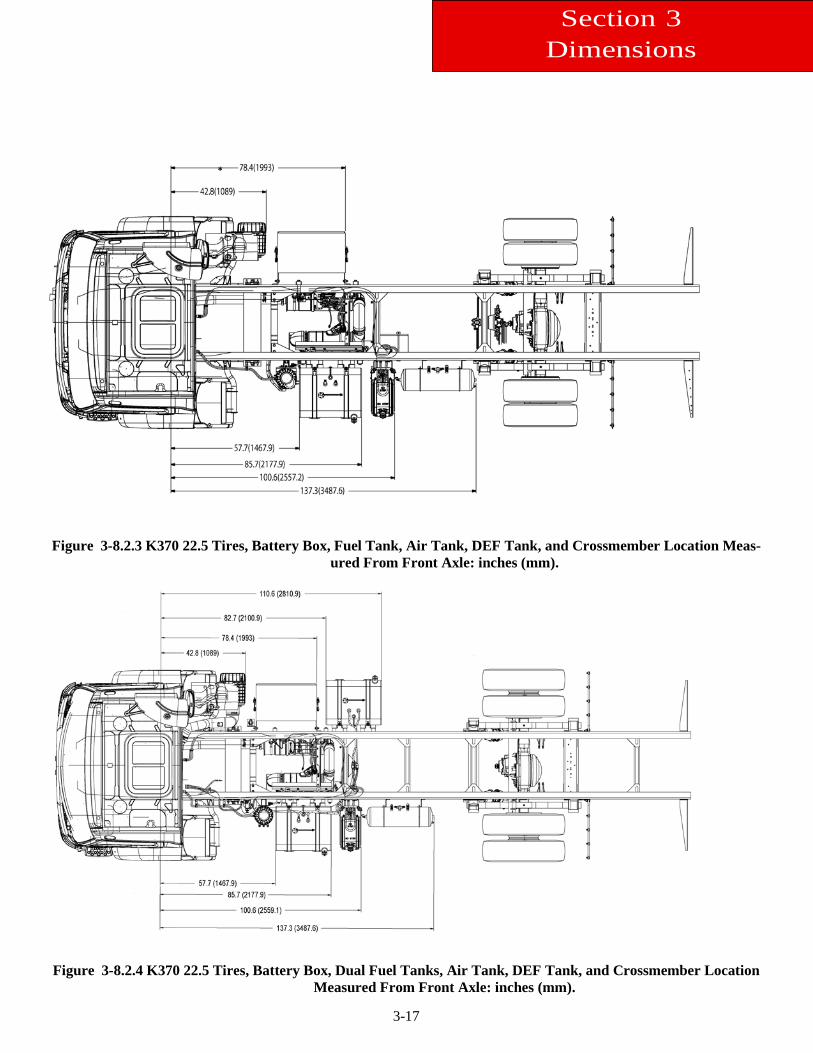
Air Tank, DEF Tank, and Crossmember Location Measured From Front Axle: inches (mm)............ 3-16 Figure 3-8.2.3 K370 22.5 Tires, Battery Box, Fuel Tank, Air Tank, DEF Tank, and Crossmember
Location Measured From Front Axle: inches (mm). ............................................................................ 3-17 Figure 3-8.2.4 K370 22.5 Tires, Battery Box, Dual Fuel Tanks, Air Tank, DEF Tank, and Crossmember
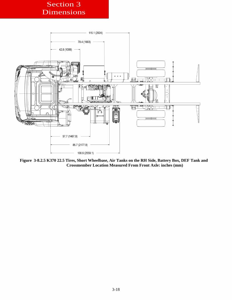
Location Measured From Front Axle: inches (mm). ............................................................................ 3-17 Figure 3-8.2.5 K370 22.5 Tires, Short Wheelbase, Air Tanks on the RH Side, Battery Box, DEF Tank
and Crossmember Location Measured From Front Axle: inches (mm) ............................................... 3-18 Figure 3-9.1. K270 Crossmember Location .......................................................................................................... 3-19 Figure 3-9.2. K370 Crossmember Locations ........................................................................................................ 3-20 Figure 3-10. K270/K370 Rail Measurements ....................................................................................................... 3-21 Figure 3-11. K270/K370 Battery Box, Fuel Tank and Air Tanks Measurement mm (in) .................................... 3-22 Figure 3-11. K270/K370 Exhaust Measurements ................................................................................................. 3-23 Figure 3-14.1 K370 PTO Clearances 1 of 2 .......................................................................................................... 3-26 Figure 3-14.2 K370 PTO Clearances 2 of 2 .......................................................................................................... 3-26 Figure 3-15 K270 PTO Clearances ....................................................................................................................... 3-27 Figure 4-1: Measurement Location of DEF Supply Module (Pump) ..................................................................... 4-4 Figure 4-2: Measurement Location of DEF Dosing Module (Injector) .................................................................. 4-4 Figure 4-3: Orientation of Dosing Module .............................................................................................................. 4-5 Figure 4-4: Routing DEF Lines and DEF Trap ....................................................................................................... 4-5 Figure 4-5: Horizontal Crossover DPF and SCR with Horizontal Tailpipe............................................................ 4-6 Figure 4-5.1: Top view of Horizontal Crossover DPF and SCR with Horizontal Tailpipe .................................. 4-6 Figure 4-5.2: Right view of Horizontal Crossover DPF and SCR with Horizontal Tailpipe ................................. 4-7 Figure 4-5.3: Back view of Horizontal Crossover DPF and SCR with Horizontal Tailpipe ................................ 4-7 Figure 5-1: Horizontal Crossover DPF/SCR, LH horizontal tailpipe, RH BOC rectangular fuel tank, RH
BOC rectangular DEF tank and LH BOC battery box ........................................................................... 5-2 Figure 5-2: Horizontal Crossover DPF/SCR, LH horizontal tailpipe, RH BOC rectangular fuel tank, RH
BOC rectangular fuel tank, RH BOC rectangular DEF tank and LH BOC battery box ........................ 5-2 Figure 5-2. Minimum Clearance Between Top Of Rear Tires And Body Structure Overhang. ............................. 5-3 Figure 5-3. Minimum Back of Cab Clearance ........................................................................................................ 5-3 Figure 5-4. Spacer Between Frame Sill and Body Rail - Rubber or Plastic ........................................................... 5-5 Figure 5-5. High Compression Spring Between the Mounting Bolt and Upper Bracket ........................................ 5-5
iv
Figures Figure 5-6. Rubber Spacer Between Brackets ......................................................................................................... 5-5 Figure 5-7. Hole Locations Guidelines for Frame Rail and Bracket ....................................................................... 5-5 Figure 5-8. Crossmember-Gusset Hole Pattern Requirements. [inch(mm)] ........................................................... 5-6 Figure 5-9. Acceptable U-Bolt Mounting with Wood and Fabricated Spacers ...................................................... 5-7 Figure 5-10. Clearance Space for Air Lines and Cables ......................................................................................... 5-7 Figure 5-11 Example of Fishplate Bracket at Rear End of Body, used with U-Bolts ............................................. 5-8 Figure 6-1. Detail of Frame ..................................................................................................................................... 6-2 Figure 6-2. Frame Insert Extension and Joint Welding ........................................................................................... 6-2 Figure 6-3 Comparison of Original, Shortened, and Extended Wheelbases. .......................................................... 6-4 Figure 6-4. Crossmember Added When Distance Exceeds 60 Inches (1524 mm) ................................................. 6-4 Figure 7-1. Instrument Layout ................................................................................................................................. 7-2 Figure 7-2. Data Bus Communication Architecture ................................................................................................ 7-3 Figure 7-2. Data Bus Communication Architecture ................................................................................................ 7-3 Figure A-2. Drivers Door and Door Frame Label .................................................................................................. A-2 Figure A-3. Engine Identification Location ........................................................................................................... A-3 Figure A-4. Front Axle Identification ..................................................................................................................... A-4 Figure A-5. Rear Axle Identification ...................................................................................................................... A-4 Figure B-1. Balanced Load: CGf 100 in. from front axle ....................................................................................... B-2 Figure B-2. Unbalanced Load: CGf 133 In. From Front Axle ................................................................................ B-3 Figure B-3. Balanced Body Unloaded: CGf 184.7 in. (4691.45 mm) from front axle. .......................................... B-5 Figure B-4. Liftgate Example: CGf 322.2 in (8183.9 mm) from front axle. .......................................................... B-5
v
Tables
Table 3-1. Abbreviations Used ............................................................................................................................ 3-1 Table 3-2 Turning Radius ........................................................................................................................................ 3-2 Table 3-3 Cab Tilt Height ........................................................................................................................................ 3-3 Table 3-4. Overall K270 W/19.5 Tires Dimensions inches (mm)........................................................................... 3-6 Table 3-5.1. Overall K370 W/19.5 Tires Dimensions .............................................................................................. 3-7 Table 3-5.2. K370 W/22.5 Tires Overall Dimensions ............................................................................................. 3-8 Table 3-6 K270 W19.5 Tires Battery Box Step and Cab Floor Measurements .................................................... 3-12 Table 3-7.1 Battery Box Step and Cab Floor Measurements w/ 19.5 Tires ......................................................... 3-13 Table 3-7.2 Battery Box Step and Cab Floor Measurements w/22.5 Tires .......................................................... 3-14 Table 3-8 Floor to Frame Measurements .............................................................................................................. 3-14 Table 3-9.1. K270 Crossmember Location Measured from the Front of the Frame inches (mm) ...................... 3-19 Table 3-9.2 K370 Crossmember Location Measured From Front Axle Centerline inches (mm) .................... 3-20 Table 3-10. Frame Rail Strength Characteristics................................................................................................... 3-21 Table 3-12. K270/K370 Exhaust Location Measured From BOC inches (mm) ................................................... 3-23 Table 3-13. K270 / K370 Exhaust Location Measured From BOC inches (mm) ................................................. 3-23 Table 5-1 Symbols ................................................................................................................................................... 5-1 Table 7-1. Additional Spare Circuits for Wiring ................................................................................................... 7-20 Table A-1. Model Year (Code) Designations. ................................................................................................... A-1 Table B-1. K270/K370 Single Rear Axle “Bare” Chassis Tare Weights (no driver, no fuel) ............................ B-4 Table B-2. K270 Weight Distribution and Chassis Rating Calculation (sample ................................................... B-7 Table B-2.1. K370 Weight Distribution and Chassis Rating Calculation (sample) ............................................... B-8 Table B-3. Available K270/K370 Body Lengths ......................................................................................... B-10
1-1
Section 1 Introduction
This manual provides body builders with appropriate information and guidelines useful in the body planning and in-stallation process. This information will be helpful when installing bodies or other associated equipment.
This manual contains appropriate dimensional information, guidelines for mounting bodies, guidelines for modifying frames, electrical wiring information, and other information useful in the body installation process.
The intended primary users of this manual are body builders who install bodies and associated equipment on K270/K370 Medium Duty vehicles. Dealers who sell and service the vehicle will also find this information useful.
This Body Builder’s Manual can be very useful when specifying a vehicle, particularly when the body builder is in-volved in the vehicle definition and ordering process. Early in the process, professional body builders can often con-tribute valuable information that reduces the ultimate cost of the body installation.
This manual is not a maintenance manual or an operation manual. • For chassis maintenance and repair information consult the PACCAR ServiceNet available in the Service De-
partment of the selling dealer or order a custom shop manual or parts catalog for your vehicle through your local dealer.
• For chassis operating information consult the Operator’s Manual, included with each vehicle. It can also be or-
dered from your local dealer.
2-1
Section 2 Safety & Compliance
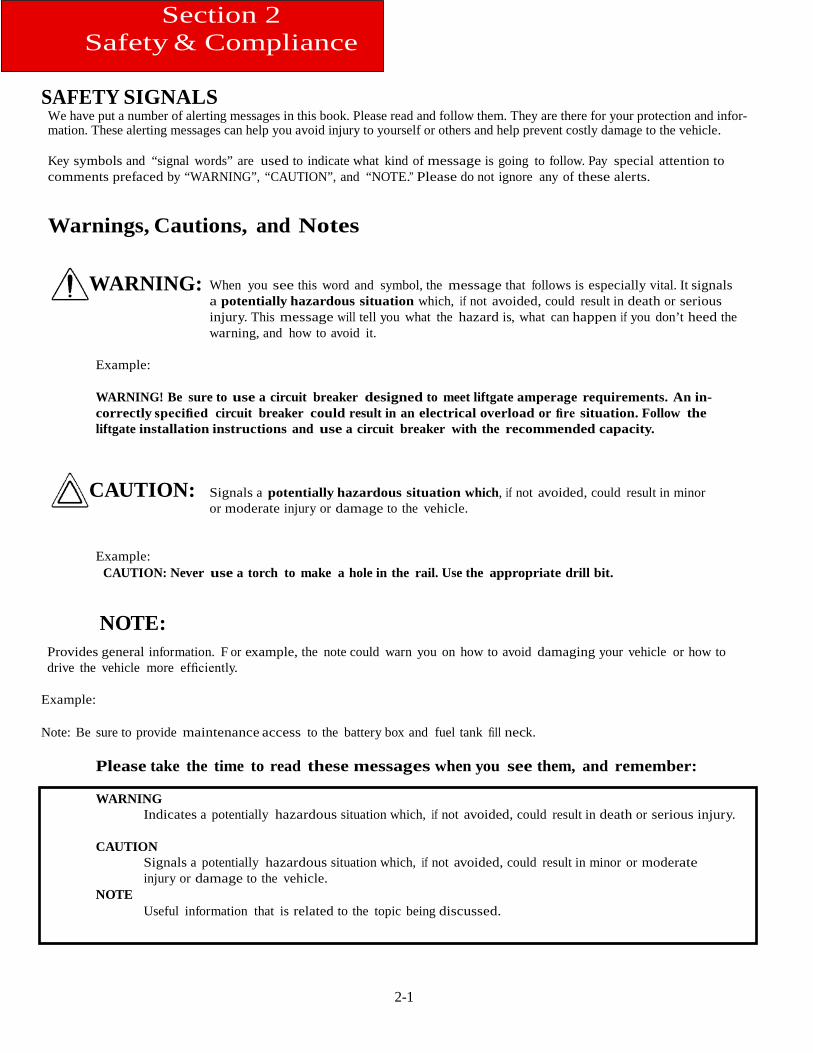
SAFETY SIGNALS We have put a number of alerting messages in this book. Please read and follow them. They are there for your protection and infor-mation. These alerting messages can help you avoid injury to yourself or others and help prevent costly damage to the vehicle.
Key symbols and “signal words” are used to indicate what kind of message is going to follow. Pay special attention to comments prefaced by “WARNING”, “CAUTION”, and “NOTE.” Please do not ignore any of these alerts.
Warnings, Cautions, and Notes
WARNING:
When you see this word and symbol, the message that follows is especially vital. It signals a potentially hazardous situation which, if not avoided, could result in death or serious injury. This message will tell you what the hazard is, what can happen if you don’t heed the warning, and how to avoid it.
Example:
WARNING! Be sure to use a circuit breaker designed to meet liftgate amperage requirements. An in-correctly specified circuit breaker could result in an electrical overload or fire situation. Follow the liftgate installation instructions and use a circuit breaker with the recommended capacity.
CAUTION: Signals a potentially hazardous situation which, if not avoided, could result in minor or moderate injury or damage to the vehicle.
Example: CAUTION: Never use a torch to make a hole in the rail. Use the appropriate drill bit.
NOTE: Provides general information. F or example, the note could warn you on how to avoid damaging your vehicle or how to drive the vehicle more efficiently.
Example: Note: Be sure to provide maintenance access to the battery box and fuel tank fill neck.
Please take the time to read these messages when you see them, and remember:
WARNING Indicates a potentially hazardous situation which, if not avoided, could result in death or serious injury.
CAUTION
Signals a potentially hazardous situation which, if not avoided, could result in minor or moderate injury or damage to the vehicle.
NOTE Useful information that is related to the topic being discussed.
2-2
Section 2 Safety & Compliance
FEDERAL MOTOR VEHICLE SAFETY STANDARDS COMPLIANCE
As an Original Equipment Manufacturer (OEM), Kenworth Truck Co. ensures that our products comply with all applicable U.S. or Canadian Federal Motor Vehicle Safety Standards. However, the fact that this vehicle has no fifth wheel and that a Body Builder (Intermediate or Final Stage Manufacturer) will be doing additional modifications means that the vehicle was incomplete when it left the build plant. See next section and Appendix A for additional information.
Incomplete Vehicle Certification
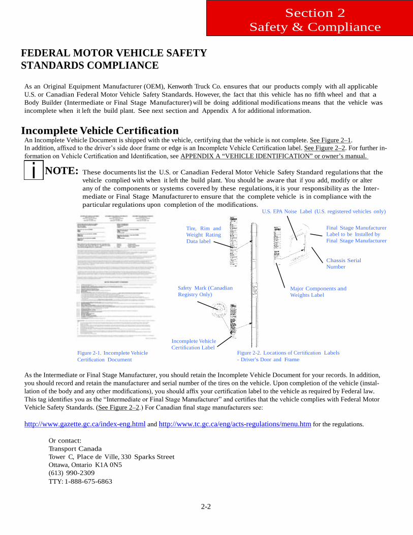
An Incomplete Vehicle Document is shipped with the vehicle, certifying that the vehicle is not complete. See Figure 2–1. In addition, affixed to the driver’s side door frame or edge is an Incomplete Vehicle Certification label. See Figure 2–2. For further in-formation on Vehicle Certification and Identification, see APPENDIX A “VEHICLE IDENTIFICATION” or owner’s manual.
NOTE: These documents list the U.S. or Canadian Federal Motor Vehicle Safety Standard regulations that the vehicle complied with when it left the build plant. You should be aware that if you add, modify or alter any of the components or systems covered by these regulations, it is your responsibility as the Inter-mediate or Final Stage Manufacturer to ensure that the complete vehicle is in compliance with the particular regulations upon completion of the modifications.
Figure 2-1. Incomplete Vehicle Certification Document
Tire, Rim and Weight Rating Data label
Safety Mark (Canadian Registry Only)
Incomplete Vehicle Certification Label
U.S. EPA Noise Label (U.S. registered vehicles only)
Final Stage Manufacturer Label to be Installed by Final Stage Manufacturer
Chassis Serial Number
Major Components and Weights Label
Figure 2-2. Locations of Certification Labels - Driver’s Door and Frame
As the Intermediate or Final Stage Manufacturer, you should retain the Incomplete Vehicle Document for your records. In addition, you should record and retain the manufacturer and serial number of the tires on the vehicle. Upon completion of the vehicle (instal-lation of the body and any other modifications), you should affix your certification label to the vehicle as required by Federal law. This tag identifies you as the “Intermediate or Final Stage Manufacturer” and certifies that the vehicle complies with Federal Motor Vehicle Safety Standards. (See Figure 2–2.) For Canadian final stage manufacturers see:
http://www.gazette.gc.ca/index-eng.html and http://www.tc.gc.ca/eng/acts-regulations/menu.htm for the regulations.
Or contact: Transport Canada Tower C, Place de Ville, 330 Sparks Street Ottawa, Ontario K1A 0N5 (613) 990-2309 TTY: 1-888-675-6863
2-3
Section 2 Safety & Compliance
Noise and Emissions Requirements
NOTE:
NOTE:
This truck may be equipped with a converter muffler unit in order to meet both noise and exhaust emissions requirements. Removal or tampering with the converter muffler will not improve engine per-formance. Also tampering is against the rules that are established by the U.S. Code of Federal Regu-lations and Environment Canada Regulations. The converter muffler may only be replaced with an approved part. Relocation of converter muffler will affect noise and emission performance. Contact the engine manu-facturer for any requirements and restrictions prior to any modifications. In particular, there are re-quirements and restrictions for exhaust pipe materials and for maximum exhaust system lengths from turbo outlet to muffler inlet.
3-1
Section 3 Dimensions
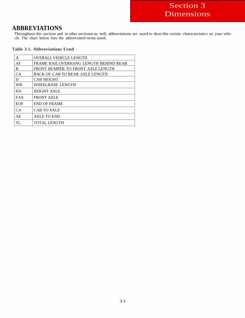
ABBREVIATIONS
Throughout this section and in other sections as well, abbreviations are used to describe certain characteristics on your vehi-cle. The chart below lists the abbreviated terms used.
Table 3-1. Abbreviations Used
A OVERALL VEHICLE LENGTH AF FRAME RAIL OVERHANG LENGTH BEHIND REAR
B FRONT BUMPER TO FRONT AXLE LENGTH CA BACK OF CAB TO REAR AXLE LENGTH D CAB HEIGHT WB WHEELBASE LENGTH HA HEIGHT AXLE FAX FRONT AXLE EOF END OF FRAME CA CAB TO AXLE AE AXLE TO END TL TOTAL LENGTH
3-2
Section 3 Dimensions
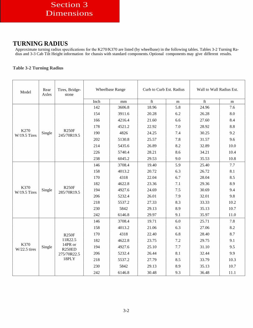
TURNING RADIUS
Approximate turning radius specifications for the K270/K370 are listed (by wheelbase) in the following tables. Tables 3-2 Turning Ra-dius and 3-3 Cab Tilt Height information for chassis with standard components. Optional components may give different results.
Table 3-2 Turning Radius
Model Rear Axles
Tires, Bridge-stone
Wheelbase Range Curb to Curb Est. Radius Wall to Wall Radius Est.
Inch mm ft m ft m
K270 W/19.5 Tires Single R250F
245/70R19.5
142 3606.8 18.96 5.8 24.96 7.6 154 3911.6 20.28 6.2 26.28 8.0 166 4216.4 21.60 6.6 27.60 8.4 178 4521.2 22.92 7.0 28.92 8.8 190 4826 24.25 7.4 30.25 9.2 202 5130.8 25.57 7.8 31.57 9.6 214 5435.6 26.89 8.2 32.89 10.0 226 5740.4 28.21 8.6 34.21 10.4 238 6045.2 29.53 9.0 35.53 10.8
K370 W/19.5 Tires Single R250F
285/70R19.5
146 3708.4 19.40 5.9 25.40 7.7 158 4013.2 20.72 6.3 26.72 8.1 170 4318 22.04 6.7 28.04 8.5 182 4622.8 23.36 7.1 29.36 8.9 194 4927.6 24.69 7.5 30.69 9.4 206 5232.4 26.01 7.9 32.01 9.8 218 5537.2 27.33 8.3 33.33 10.2 230 5842 29.13 8.9 35.13 10.7 242 6146.8 29.97 9.1 35.97 11.0
K370 W/22.5 tires Single
R250F 11R22.5 14PR or R250ED
275/70R22.5 18PLY
146 3708.4 19.71 6.0 25.71 7.8 158 4013.2 21.06 6.3 27.06 8.2 170 4318 22.40 6.8 28.40 8.7 182 4622.8 23.75 7.2 29.75 9.1 194 4927.6 25.10 7.7 31.10 9.5 206 5232.4 26.44 8.1 32.44 9.9 218 5537.2 27.79 8.5 33.79 10.3 230 5842 29.13 8.9 35.13 10.7 242 6146.8 30.48 9.3 36.48 11.1
3-3
Section 3 Dimensions
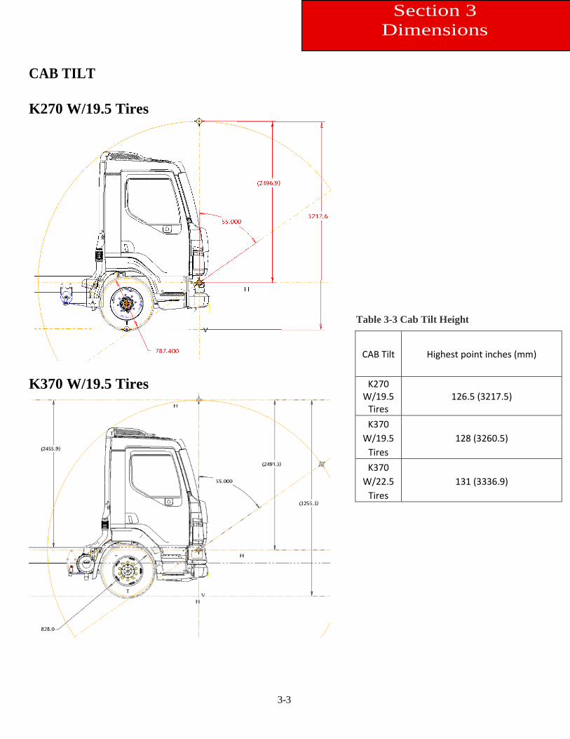
CAB TILT K270 W/19.5 Tires
K370 W/19.5 Tires
Table 3-3 Cab Tilt Height
CAB Tilt Highest point inches (mm) K270
W/19.5 Tires
126.5 (3217.5) K370
W/19.5 Tires
128 (3260.5) K370
W/22.5 Tires
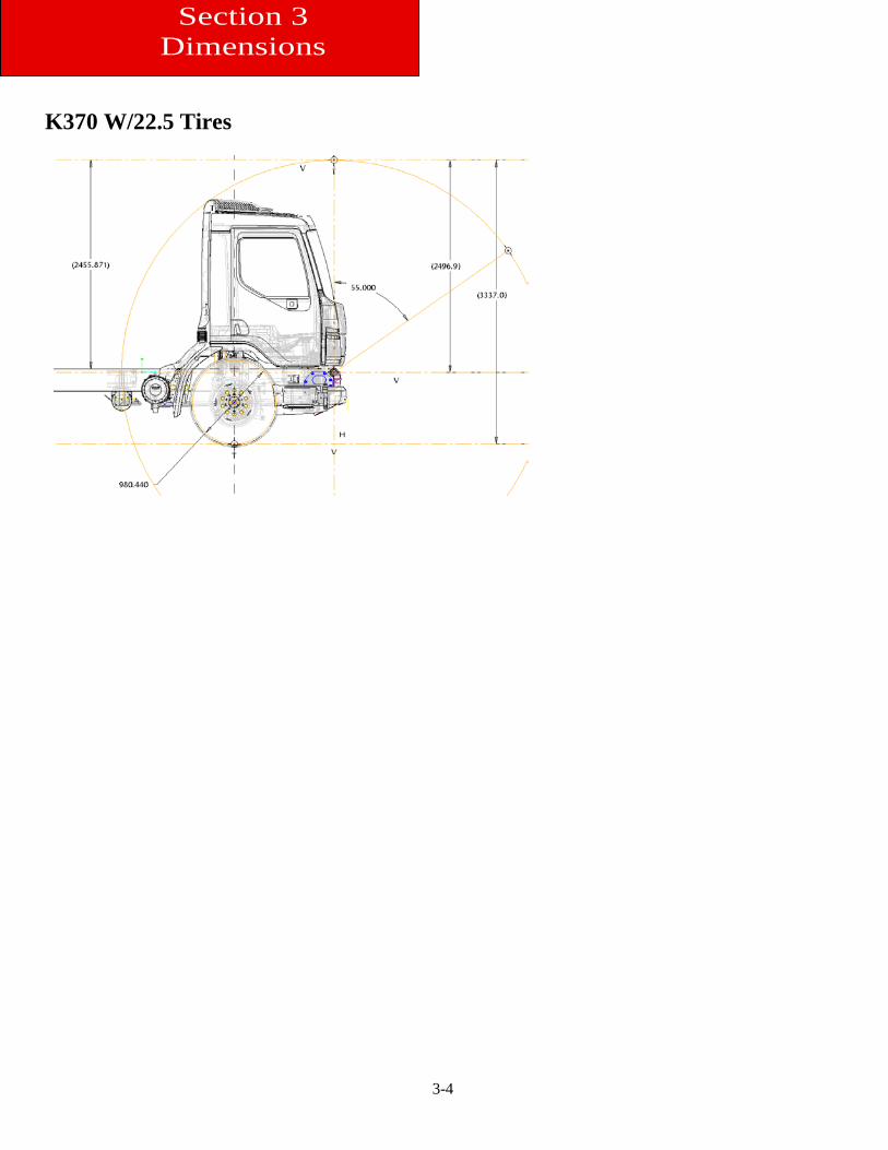
131 (3336.9)
3-4
Section 3 Dimensions
K370 W/22.5 Tires
3-5
Section 3 Dimensions
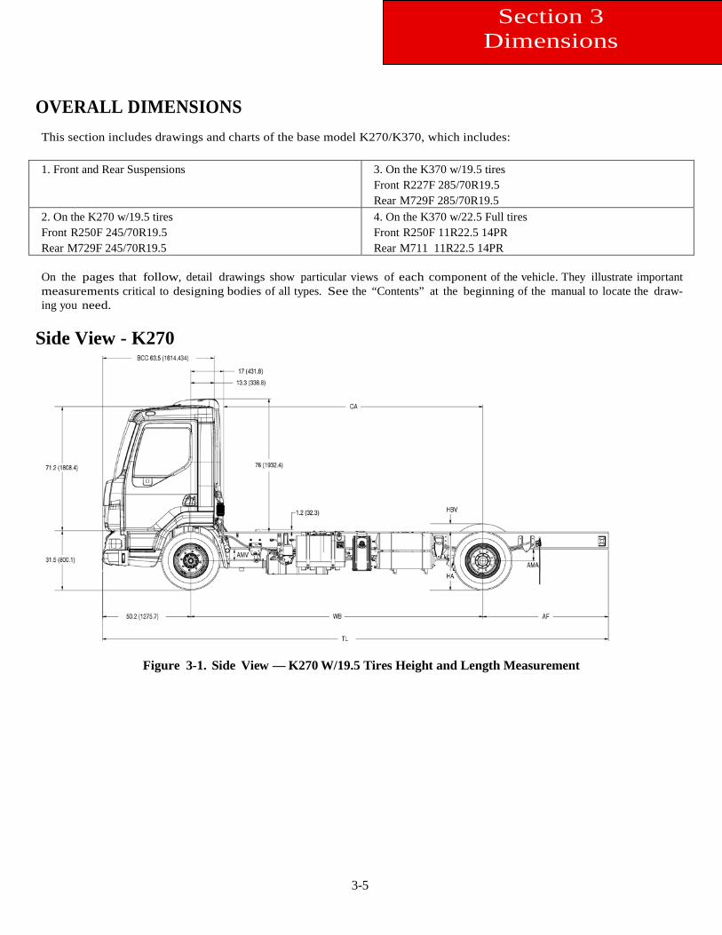
OVERALL DIMENSIONS This section includes drawings and charts of the base model K270/K370, which includes: 1. Front and Rear Suspensions 3. On the K370 w/19.5 tires
Front R227F 285/70R19.5 Rear M729F 285/70R19.5
2. On the K270 w/19.5 tires Front R250F 245/70R19.5 Rear M729F 245/70R19.5
4. On the K370 w/22.5 Full tires Front R250F 11R22.5 14PR Rear M711 11R22.5 14PR
On the pages that follow, detail drawings show particular views of each component of the vehicle. They illustrate important measurements critical to designing bodies of all types. See the “Contents” at the beginning of the manual to locate the draw-ing you need.
Side View - K270
Figure 3-1. Side View — K270 W/19.5 Tires Height and Length Measurement
3-6
Section 3 Dimensions
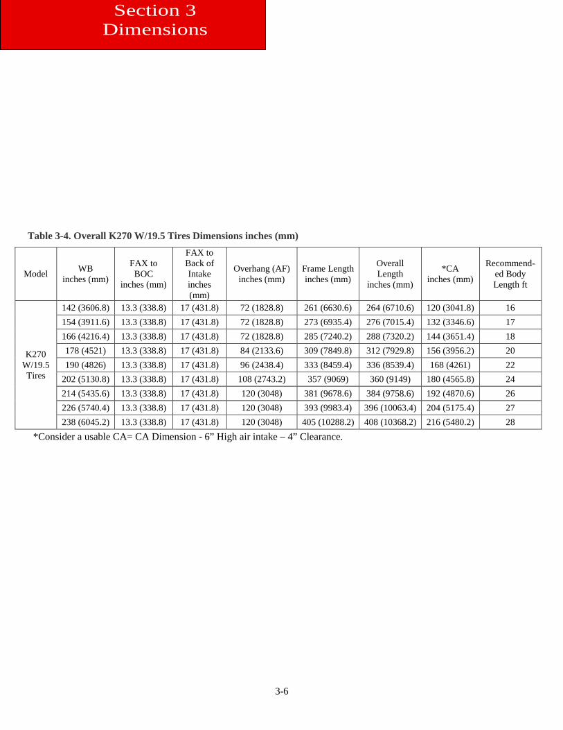
Table 3-4. Overall K270 W/19.5 Tires Dimensions inches (mm)
Model WB inches (mm)
FAX to BOC
inches (mm)
FAX to Back of Intake inches (mm)
Overhang (AF) inches (mm)
Frame Length inches (mm)
Overall Length
inches (mm)
*CA inches (mm)
Recommend-ed Body Length ft
K270 W/19.5 Tires
142 (3606.8) 13.3 (338.8) 17 (431.8) 72 (1828.8) 261 (6630.6) 264 (6710.6) 120 (3041.8) 16 154 (3911.6) 13.3 (338.8) 17 (431.8) 72 (1828.8) 273 (6935.4) 276 (7015.4) 132 (3346.6) 17 166 (4216.4) 13.3 (338.8) 17 (431.8) 72 (1828.8) 285 (7240.2) 288 (7320.2) 144 (3651.4) 18 178 (4521) 13.3 (338.8) 17 (431.8) 84 (2133.6) 309 (7849.8) 312 (7929.8) 156 (3956.2) 20 190 (4826) 13.3 (338.8) 17 (431.8) 96 (2438.4) 333 (8459.4) 336 (8539.4) 168 (4261) 22
202 (5130.8) 13.3 (338.8) 17 (431.8) 108 (2743.2) 357 (9069) 360 (9149) 180 (4565.8) 24 214 (5435.6) 13.3 (338.8) 17 (431.8) 120 (3048) 381 (9678.6) 384 (9758.6) 192 (4870.6) 26 226 (5740.4) 13.3 (338.8) 17 (431.8) 120 (3048) 393 (9983.4) 396 (10063.4) 204 (5175.4) 27 238 (6045.2) 13.3 (338.8) 17 (431.8) 120 (3048) 405 (10288.2) 408 (10368.2) 216 (5480.2) 28
*Consider a usable CA= CA Dimension - 6” High air intake – 4” Clearance.
3-7
Section 3 Dimensions
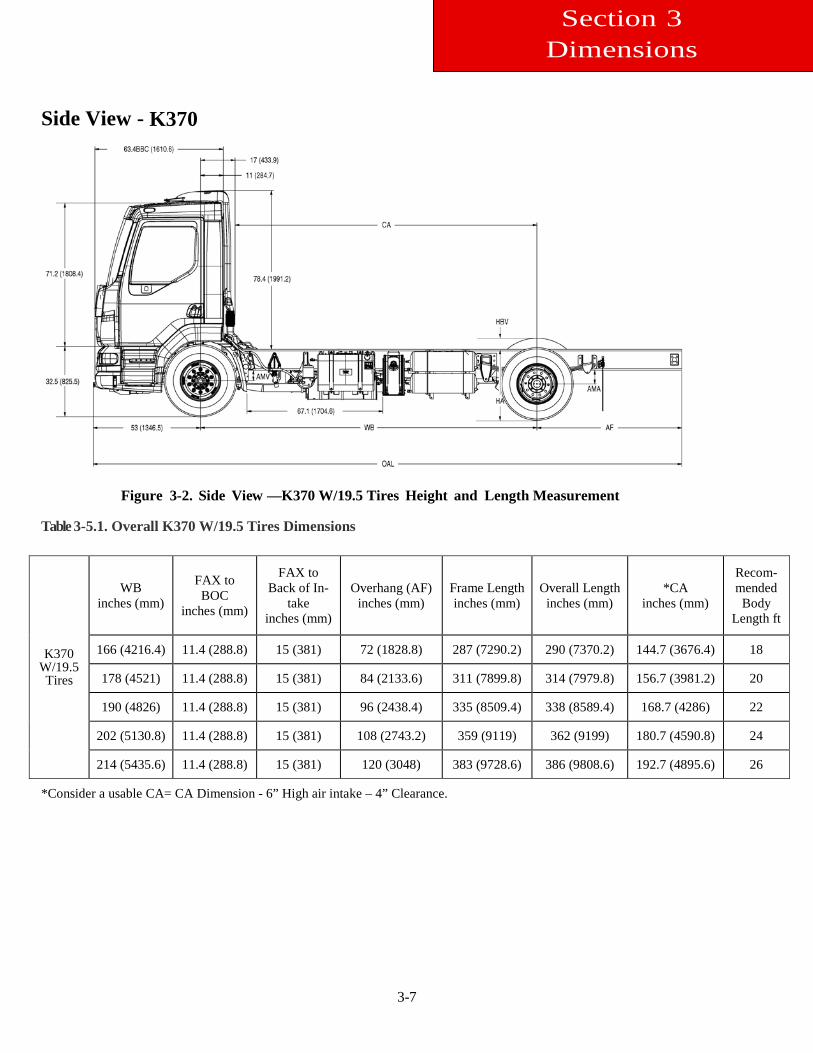
Side View - K370
Figure 3-2. Side View —K370 W/19.5 Tires Height and Length Measurement
Table 3-5.1. Overall K370 W/19.5 Tires Dimensions
K370 W/19.5 Tires
WB inches (mm)
FAX to BOC
inches (mm)
FAX to Back of In-
take inches (mm)
Overhang (AF) inches (mm)
Frame Length inches (mm)
Overall Length inches (mm)
*CA inches (mm)
Recom-mended
Body Length ft
166 (4216.4) 11.4 (288.8) 15 (381) 72 (1828.8) 287 (7290.2) 290 (7370.2) 144.7 (3676.4) 18
178 (4521) 11.4 (288.8) 15 (381) 84 (2133.6) 311 (7899.8) 314 (7979.8) 156.7 (3981.2) 20
190 (4826) 11.4 (288.8) 15 (381) 96 (2438.4) 335 (8509.4) 338 (8589.4) 168.7 (4286) 22
202 (5130.8) 11.4 (288.8) 15 (381) 108 (2743.2) 359 (9119) 362 (9199) 180.7 (4590.8) 24
214 (5435.6) 11.4 (288.8) 15 (381) 120 (3048) 383 (9728.6) 386 (9808.6) 192.7 (4895.6) 26
*Consider a usable CA= CA Dimension - 6” High air intake – 4” Clearance.
3-8
Section 3 Dimensions
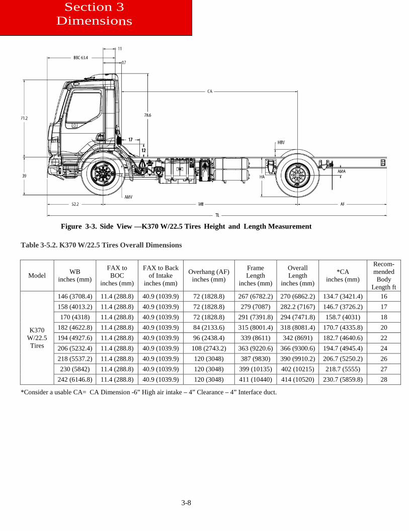
Figure 3-3. Side View —K370 W/22.5 Tires Height and Length Measurement
Table 3-5.2. K370 W/22.5 Tires Overall Dimensions
Model WB inches (mm)
FAX to BOC
inches (mm)
FAX to Back of Intake
inches (mm)
Overhang (AF) inches (mm)
Frame Length
inches (mm)
Overall Length
inches (mm)
*CA inches (mm)
Recom-mended Body
Length ft
K370 W/22.5 Tires
146 (3708.4) 11.4 (288.8) 40.9 (1039.9) 72 (1828.8) 267 (6782.2) 270 (6862.2) 134.7 (3421.4) 16 158 (4013.2) 11.4 (288.8) 40.9 (1039.9) 72 (1828.8) 279 (7087) 282.2 (7167) 146.7 (3726.2) 17 170 (4318) 11.4 (288.8) 40.9 (1039.9) 72 (1828.8) 291 (7391.8) 294 (7471.8) 158.7 (4031) 18
182 (4622.8) 11.4 (288.8) 40.9 (1039.9) 84 (2133.6) 315 (8001.4) 318 (8081.4) 170.7 (4335.8) 20 194 (4927.6) 11.4 (288.8) 40.9 (1039.9) 96 (2438.4) 339 (8611) 342 (8691) 182.7 (4640.6) 22 206 (5232.4) 11.4 (288.8) 40.9 (1039.9) 108 (2743.2) 363 (9220.6) 366 (9300.6) 194.7 (4945.4) 24 218 (5537.2) 11.4 (288.8) 40.9 (1039.9) 120 (3048) 387 (9830) 390 (9910.2) 206.7 (5250.2) 26 230 (5842) 11.4 (288.8) 40.9 (1039.9) 120 (3048) 399 (10135) 402 (10215) 218.7 (5555) 27
242 (6146.8) 11.4 (288.8) 40.9 (1039.9) 120 (3048) 411 (10440) 414 (10520) 230.7 (5859.8) 28
*Consider a usable CA= CA Dimension -6” High air intake – 4” Clearance – 4” Interface duct.
3-9
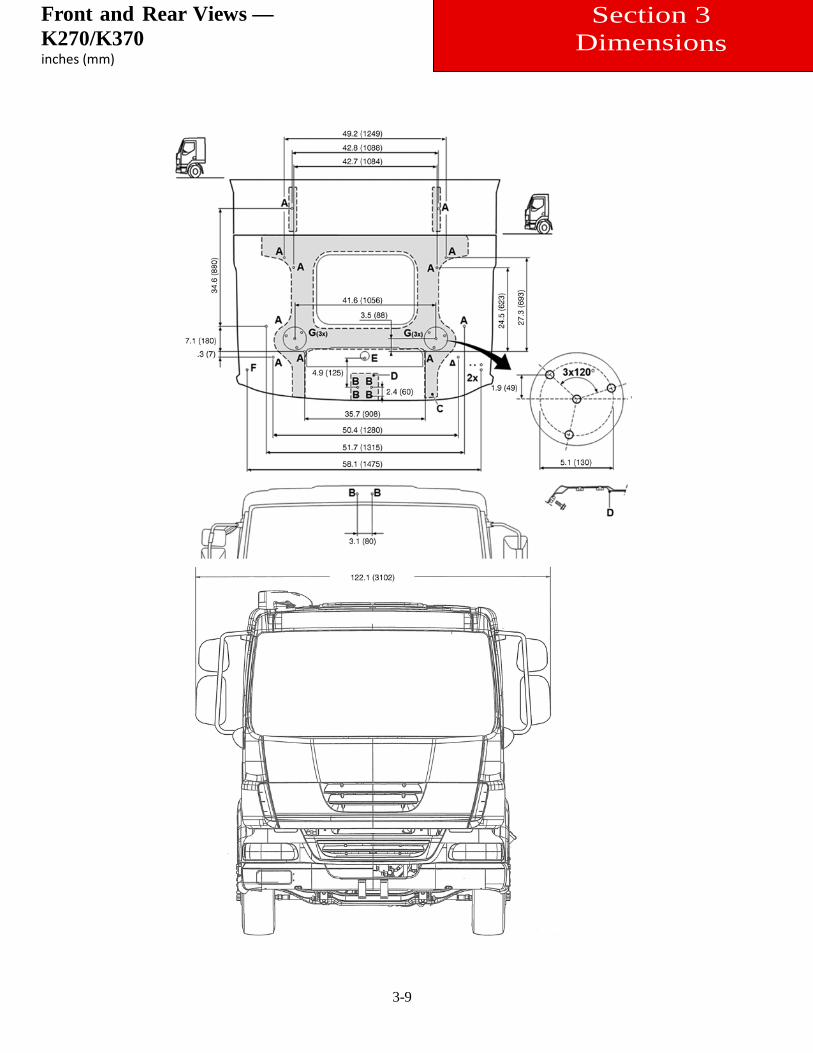
Front and Rear Views — K270/K370 inches (mm)
Section 3 Dimensions
3-10
Section 3 Dimensions
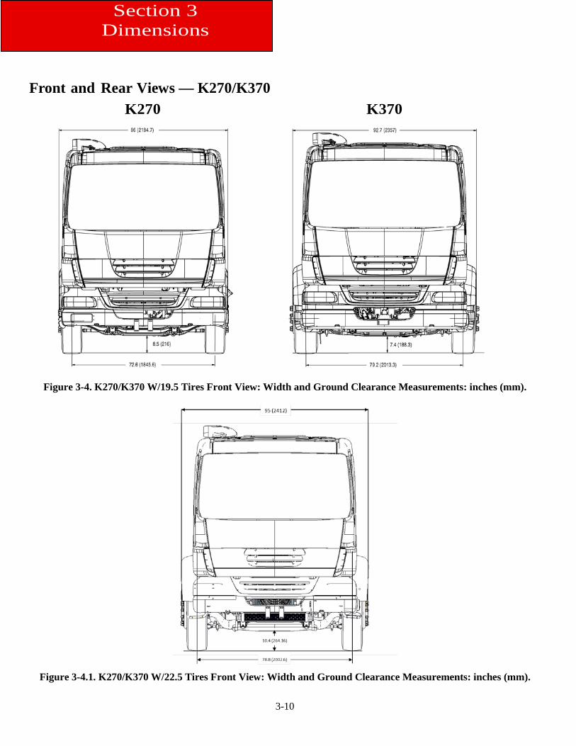
Front and Rear Views — K270/K370 K270 K370
Figure 3-4. K270/K370 W/19.5 Tires Front View: Width and Ground Clearance Measurements: inches (mm).
Figure 3-4.1. K270/K370 W/22.5 Tires Front View: Width and Ground Clearance Measurements: inches (mm).
3-11
Section 3 Dimensions
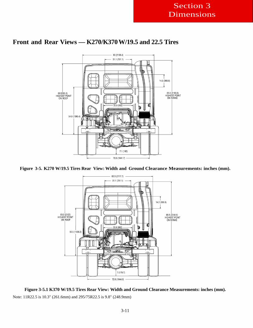
Front and Rear Views — K270/K370 W/19.5 and 22.5 Tires
Figure 3-5. K270 W/19.5 Tires Rear View: Width and Ground Clearance Measurements: inches (mm).
Figure 3-5.1 K370 W/19.5 Tires Rear View: Width and Ground Clearance Measurements: inches (mm).
Note: 11R22.5 is 10.3" (261.6mm) and 295/75R22.5 is 9.8" (248.9mm)
3-12
.Section 3 Dimensions
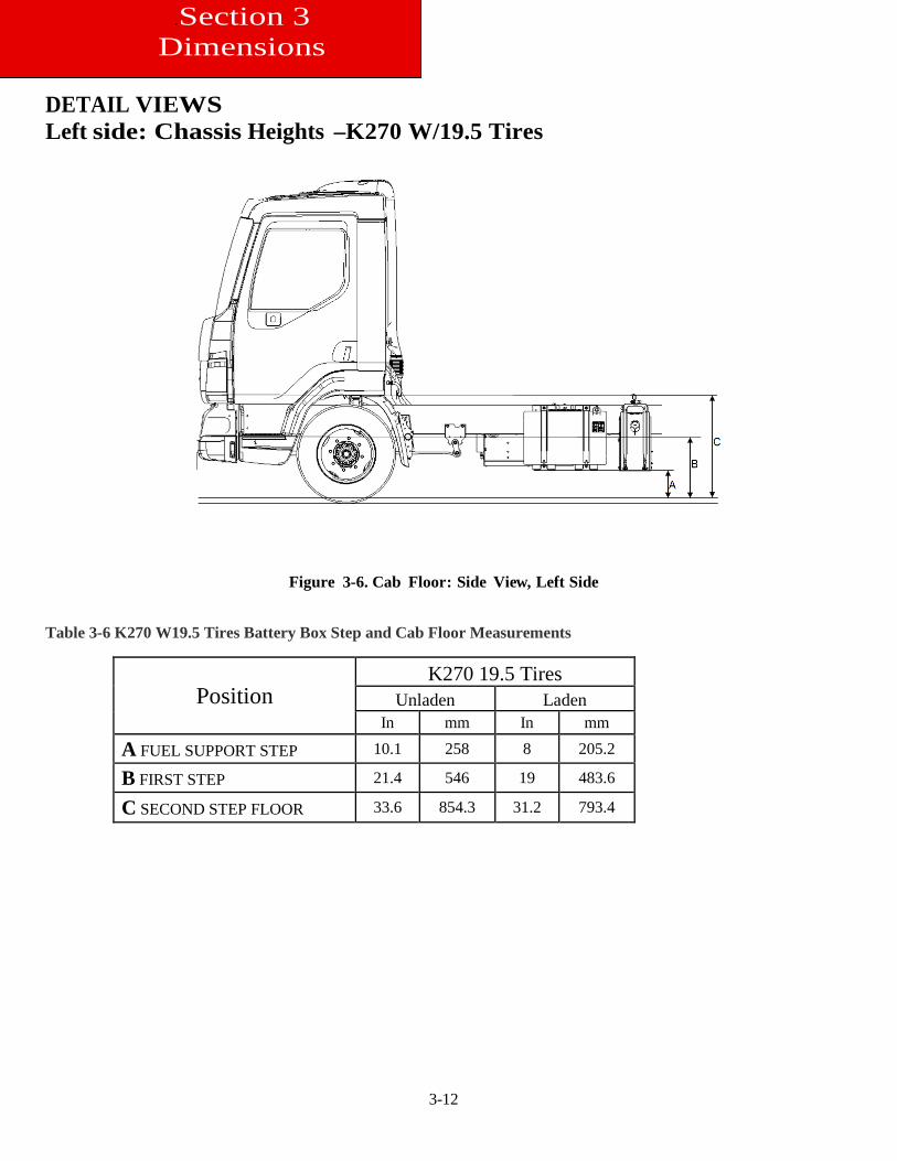
DETAIL VIEWS Left side: Chassis Heights –K270 W/19.5 Tires
Figure 3-6. Cab Floor: Side View, Left Side Table 3-6 K270 W19.5 Tires Battery Box Step and Cab Floor Measurements
Position K270 19.5 Tires
Unladen Laden In mm In mm
A FUEL SUPPORT STEP 10.1 258 8 205.2
B FIRST STEP 21.4 546 19 483.6
C SECOND STEP FLOOR 33.6 854.3 31.2 793.4
3-13
Section 3 Dimensions
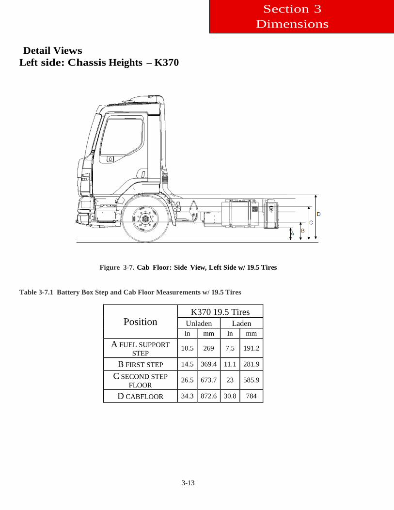
Detail Views Left side: Chassis Heights – K370
Figure 3-7. Cab Floor: Side View, Left Side w/ 19.5 Tires
Table 3-7.1 Battery Box Step and Cab Floor Measurements w/ 19.5 Tires
Position K370 19.5 Tires
Unladen Laden In mm In mm
A FUEL SUPPORT STEP
10.5 269 7.5 191.2
B FIRST STEP 14.5 369.4 11.1 281.9
C SECOND STEP FLOOR
26.5 673.7 23 585.9
D CABFLOOR 34.3 872.6 30.8 784
3-14
Section 3 Dimensions
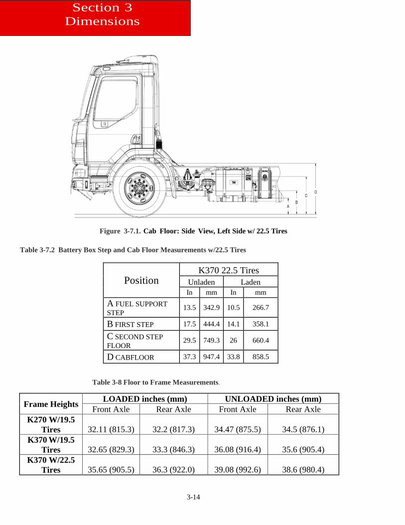
Figure 3-7.1. Cab Floor: Side View, Left Side w/ 22.5 Tires
Table 3-7.2 Battery Box Step and Cab Floor Measurements w/22.5 Tires
Position K370 22.5 Tires
Unladen Laden In mm In mm
A FUEL SUPPORT STEP
13.5 342.9 10.5 266.7
B FIRST STEP 17.5 444.4 14.1 358.1
C SECOND STEP FLOOR
29.5 749.3 26 660.4
D CABFLOOR 37.3 947.4 33.8 858.5
Table 3-8 Floor to Frame Measurements.
Frame Heights LOADED inches (mm) UNLOADED inches (mm) Front Axle Rear Axle Front Axle Rear Axle
K270 W/19.5 Tires 32.11 (815.3) 32.2 (817.3) 34.47 (875.5) 34.5 (876.1)
K370 W/19.5 Tires 32.65 (829.3) 33.3 (846.3) 36.08 (916.4) 35.6 (905.4)
K370 W/22.5 Tires 35.65 (905.5) 36.3 (922.0) 39.08 (992.6) 38.6 (980.4)
3-15
Section 3 Dimensions
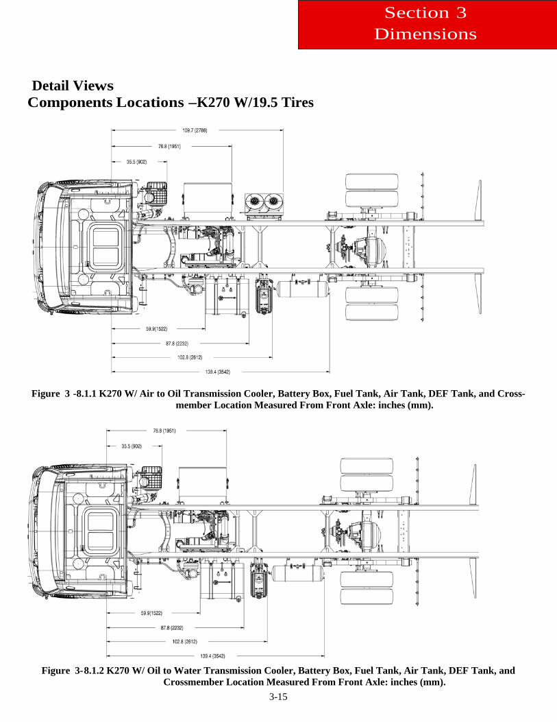
Detail Views Components Locations –K270 W/19.5 Tires
Figure 3 -8.1.1 K270 W/ Air to Oil Transmission Cooler, Battery Box, Fuel Tank, Air Tank, DEF Tank, and Cross-
member Location Measured From Front Axle: inches (mm).
Figure 3-8.1.2 K270 W/ Oil to Water Transmission Cooler, Battery Box, Fuel Tank, Air Tank, DEF Tank, and
Crossmember Location Measured From Front Axle: inches (mm).
3-16
Section 3 Dimensions
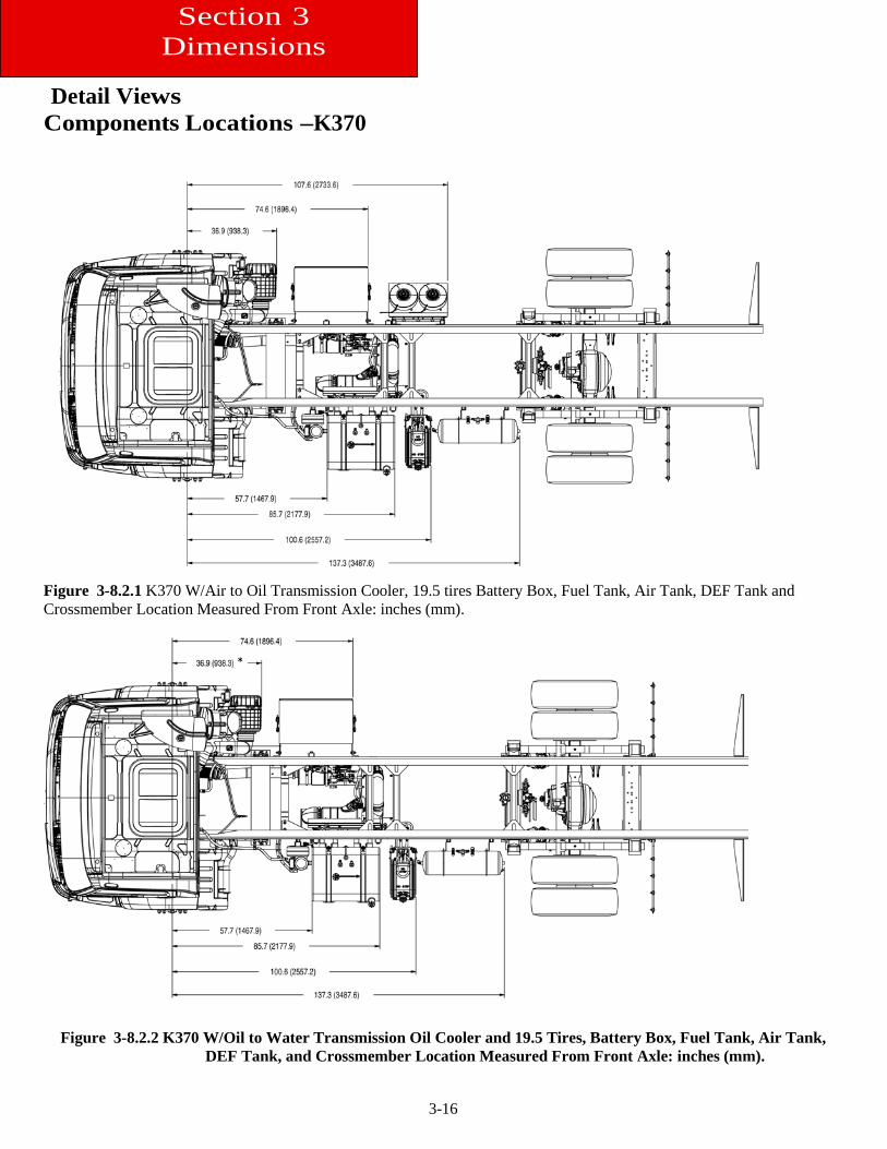
Detail Views Components Locations –K370
Figure 3-8.2.1 K370 W/Air to Oil Transmission Cooler, 19.5 tires Battery Box, Fuel Tank, Air Tank, DEF Tank and Crossmember Location Measured From Front Axle: inches (mm).
Figure 3-8.2.2 K370 W/Oil to Water Transmission Oil Cooler and 19.5 Tires, Battery Box, Fuel Tank, Air Tank, DEF Tank, and Crossmember Location Measured From Front Axle: inches (mm).
*
3-17
Section 3 Dimensions
Figure 3-8.2.3 K370 22.5 Tires, Battery Box, Fuel Tank, Air Tank, DEF Tank, and Crossmember Location Meas-ured From Front Axle: inches (mm).
Figure 3-8.2.4 K370 22.5 Tires, Battery Box, Dual Fuel Tanks, Air Tank, DEF Tank, and Crossmember Location
Measured From Front Axle: inches (mm).
*
3-18
Section 3 Dimensions
Figure 3-8.2.5 K370 22.5 Tires, Short Wheelbase, Air Tanks on the RH Side, Battery Box, DEF Tank and
Crossmember Location Measured From Front Axle: inches (mm)
3-19
Section 3 Dimensions
Detail Views
Crossmember Locations –K270 W/19.5 Tires
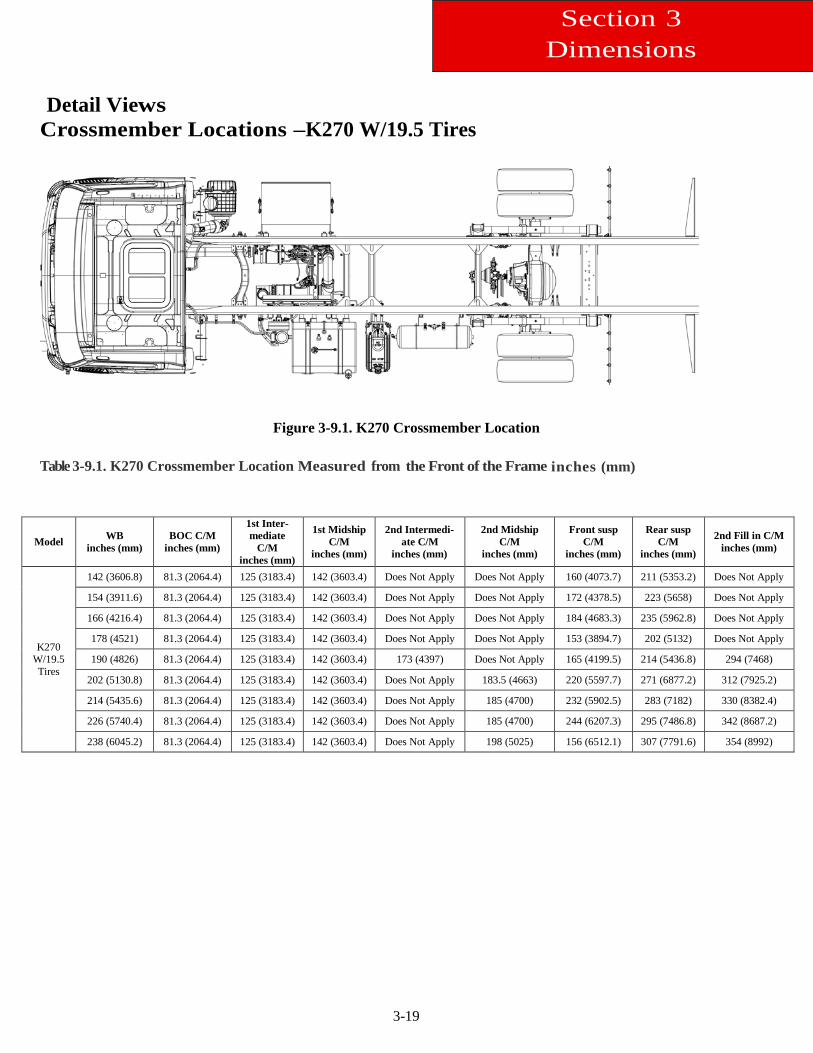
Figure 3-9.1. K270 Crossmember Location Table 3-9.1. K270 Crossmember Location Measured from the Front of the Frame inches (mm)
Model WB inches (mm)
BOC C/M inches (mm)
1st Inter-mediate
C/M inches (mm)
1st Midship C/M
inches (mm)
2nd Intermedi-ate C/M
inches (mm)
2nd Midship C/M
inches (mm)
Front susp C/M
inches (mm)
Rear susp C/M
inches (mm)
2nd Fill in C/M inches (mm)
K270 W/19.5 Tires
142 (3606.8) 81.3 (2064.4) 125 (3183.4) 142 (3603.4) Does Not Apply Does Not Apply 160 (4073.7) 211 (5353.2) Does Not Apply
154 (3911.6) 81.3 (2064.4) 125 (3183.4) 142 (3603.4) Does Not Apply Does Not Apply 172 (4378.5) 223 (5658) Does Not Apply
166 (4216.4) 81.3 (2064.4) 125 (3183.4) 142 (3603.4) Does Not Apply Does Not Apply 184 (4683.3) 235 (5962.8) Does Not Apply
178 (4521) 81.3 (2064.4) 125 (3183.4) 142 (3603.4) Does Not Apply Does Not Apply 153 (3894.7) 202 (5132) Does Not Apply
190 (4826) 81.3 (2064.4) 125 (3183.4) 142 (3603.4) 173 (4397) Does Not Apply 165 (4199.5) 214 (5436.8) 294 (7468)
202 (5130.8) 81.3 (2064.4) 125 (3183.4) 142 (3603.4) Does Not Apply 183.5 (4663) 220 (5597.7) 271 (6877.2) 312 (7925.2)
214 (5435.6) 81.3 (2064.4) 125 (3183.4) 142 (3603.4) Does Not Apply 185 (4700) 232 (5902.5) 283 (7182) 330 (8382.4)
226 (5740.4) 81.3 (2064.4) 125 (3183.4) 142 (3603.4) Does Not Apply 185 (4700) 244 (6207.3) 295 (7486.8) 342 (8687.2)
238 (6045.2) 81.3 (2064.4) 125 (3183.4) 142 (3603.4) Does Not Apply 198 (5025) 156 (6512.1) 307 (7791.6) 354 (8992)
3-20
Section 3 Dimensions
Detail Views Crossmember Locations –K370
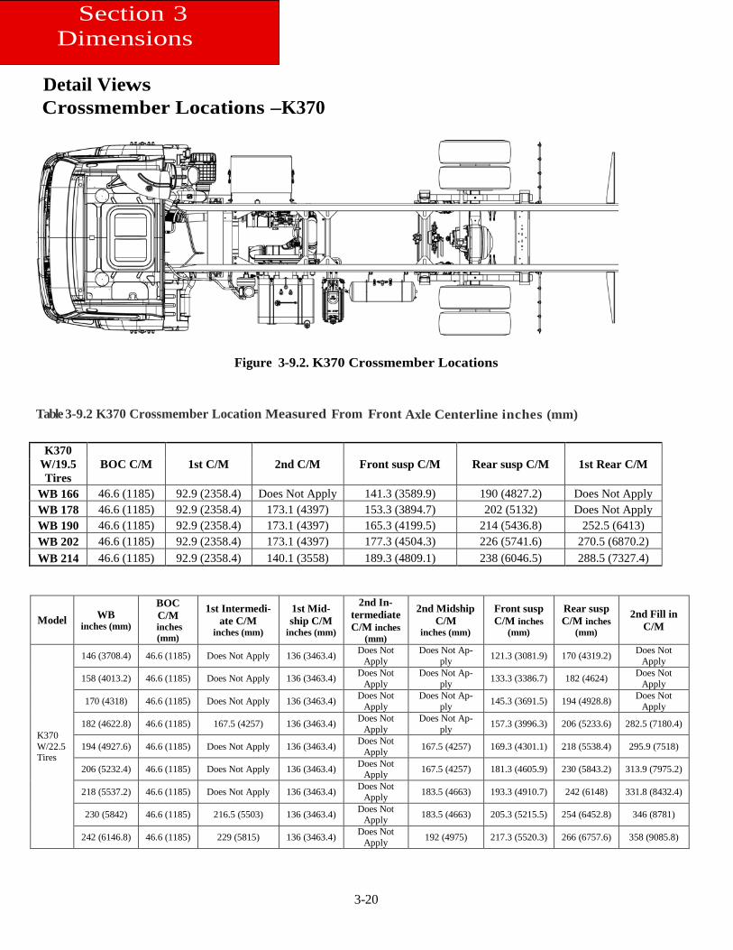
Figure 3-9.2. K370 Crossmember Locations Table 3-9.2 K370 Crossmember Location Measured From Front Axle Centerline inches (mm)
Model WB inches (mm)
BOC C/M
inches (mm)
1st Intermedi-ate C/M
inches (mm)
1st Mid-ship C/M
inches (mm)
2nd In-termediate C/M inches
(mm)
2nd Midship C/M
inches (mm)
Front susp C/M inches
(mm)
Rear susp C/M inches
(mm)
2nd Fill in C/M
K370 W/22.5 Tires
146 (3708.4) 46.6 (1185) Does Not Apply 136 (3463.4) Does Not Apply
Does Not Ap-ply 121.3 (3081.9) 170 (4319.2) Does Not
Apply
158 (4013.2) 46.6 (1185) Does Not Apply 136 (3463.4) Does Not Apply
Does Not Ap-ply 133.3 (3386.7) 182 (4624) Does Not
Apply
170 (4318) 46.6 (1185) Does Not Apply 136 (3463.4) Does Not Apply
Does Not Ap-ply 145.3 (3691.5) 194 (4928.8) Does Not
Apply
182 (4622.8) 46.6 (1185) 167.5 (4257) 136 (3463.4) Does Not Apply
Does Not Ap-ply 157.3 (3996.3) 206 (5233.6) 282.5 (7180.4)
194 (4927.6) 46.6 (1185) Does Not Apply 136 (3463.4) Does Not Apply 167.5 (4257) 169.3 (4301.1) 218 (5538.4) 295.9 (7518)
206 (5232.4) 46.6 (1185) Does Not Apply 136 (3463.4) Does Not Apply 167.5 (4257) 181.3 (4605.9) 230 (5843.2) 313.9 (7975.2)
218 (5537.2) 46.6 (1185) Does Not Apply 136 (3463.4) Does Not Apply 183.5 (4663) 193.3 (4910.7) 242 (6148) 331.8 (8432.4)
230 (5842) 46.6 (1185) 216.5 (5503) 136 (3463.4) Does Not Apply 183.5 (4663) 205.3 (5215.5) 254 (6452.8) 346 (8781)
242 (6146.8) 46.6 (1185) 229 (5815) 136 (3463.4) Does Not Apply 192 (4975) 217.3 (5520.3) 266 (6757.6) 358 (9085.8)
K370 W/19.5 Tires
BOC C/M 1st C/M 2nd C/M Front susp C/M Rear susp C/M 1st Rear C/M
WB 166 46.6 (1185) 92.9 (2358.4) Does Not Apply 141.3 (3589.9) 190 (4827.2) Does Not Apply WB 178 46.6 (1185) 92.9 (2358.4) 173.1 (4397) 153.3 (3894.7) 202 (5132) Does Not Apply WB 190 46.6 (1185) 92.9 (2358.4) 173.1 (4397) 165.3 (4199.5) 214 (5436.8) 252.5 (6413) WB 202 46.6 (1185) 92.9 (2358.4) 173.1 (4397) 177.3 (4504.3) 226 (5741.6) 270.5 (6870.2) WB 214 46.6 (1185) 92.9 (2358.4) 140.1 (3558) 189.3 (4809.1) 238 (6046.5) 288.5 (7327.4)
3-21
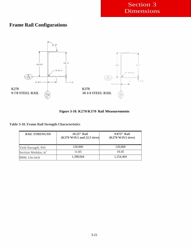
Frame Rail Configurations K270 K370 9-7/8 STEEL RAIL 10-1/4 STEEL RAIL
Figure 3-10. K270/K370 Rail Measurements
Table 3-10. Frame Rail Strength Characteristics
RAIL STRENGTH 10.25” Rail (K370 W19.5 and 22.5 tires)
9.875” Rail (K270 W19.5 tires)
Yield Strength, PSI 120,000
120,000 Section Modulus, in3 11.65
10.45
RBM, Lbs-Inch 1,398,664
1,254,404
Section 3 Dimensions
3-22
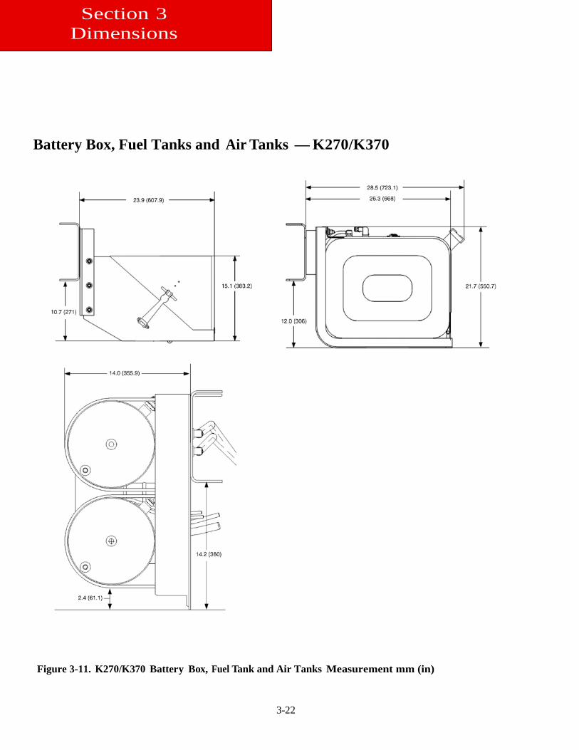
Battery Box, Fuel Tanks and Air Tanks — K270/K370
Figure 3-11. K270/K370 Battery Box, Fuel Tank and Air Tanks Measurement mm (in)
Section 3 Dimensions
3-23
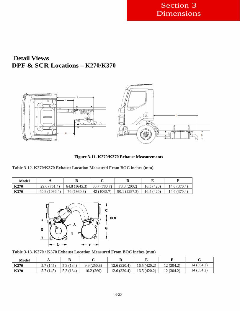
Detail Views DPF & SCR Locations – K270/K370
Figure 3-11. K270/K370 Exhaust Measurements
Table 3-12. K270/K370 Exhaust Location Measured From BOC inches (mm)
Model A B C D E F
K270 29.6 (751.4) 64.8 (1645.3) 30.7 (780.7) 78.8 (2002) 16.5 (420) 14.6 (370.4) K370 40.8 (1036.4) 76 (1930.3) 42 (1065.7) 90.1 (2287.3) 16.5 (420) 14.6 (370.4)
Table 3-13. K270 / K370 Exhaust Location Measured From BOC inches (mm)
Model A B C D E F G K270 5.7 (145) 5.3 (134) 9.9 (250.8) 12.6 (320.4) 16.5 (420.2) 12 (304.2) 14 (354.2) K370 5.7 (145) 5.3 (134) 10.2 (260) 12.6 (320.4) 16.5 (420.2) 12 (304.2) 14 (354.2)
Section 3 Dimensions
3-24
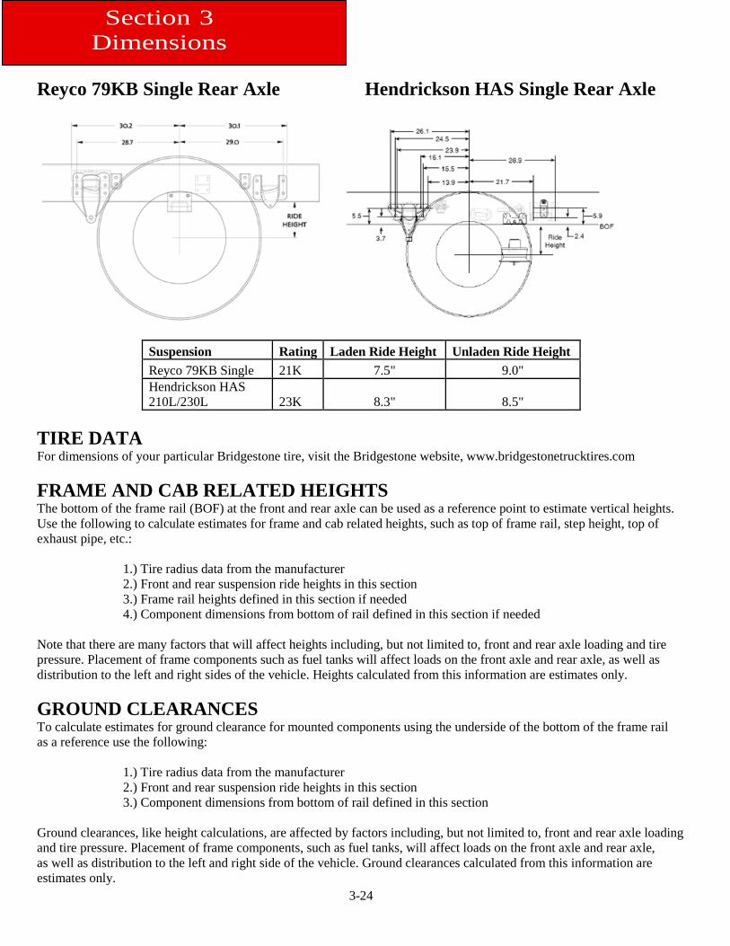
Reyco 79KB Single Rear Axle Hendrickson HAS Single Rear Axle
Suspension Rating Laden Ride Height Unladen Ride Height Reyco 79KB Single 21K 7.5" 9.0" Hendrickson HAS 210L/230L 23K 8.3" 8.5"
TIRE DATA For dimensions of your particular Bridgestone tire, visit the Bridgestone website, www.bridgestonetrucktires.com FRAME AND CAB RELATED HEIGHTS The bottom of the frame rail (BOF) at the front and rear axle can be used as a reference point to estimate vertical heights. Use the following to calculate estimates for frame and cab related heights, such as top of frame rail, step height, top of exhaust pipe, etc.:
1.) Tire radius data from the manufacturer 2.) Front and rear suspension ride heights in this section 3.) Frame rail heights defined in this section if needed 4.) Component dimensions from bottom of rail defined in this section if needed
Note that there are many factors that will affect heights including, but not limited to, front and rear axle loading and tire pressure. Placement of frame components such as fuel tanks will affect loads on the front axle and rear axle, as well as distribution to the left and right sides of the vehicle. Heights calculated from this information are estimates only. GROUND CLEARANCES To calculate estimates for ground clearance for mounted components using the underside of the bottom of the frame rail as a reference use the following:
1.) Tire radius data from the manufacturer 2.) Front and rear suspension ride heights in this section 3.) Component dimensions from bottom of rail defined in this section
Ground clearances, like height calculations, are affected by factors including, but not limited to, front and rear axle loading and tire pressure. Placement of frame components, such as fuel tanks, will affect loads on the front axle and rear axle, as well as distribution to the left and right side of the vehicle. Ground clearances calculated from this information are estimates only.
Section 3 Dimensions
3-25
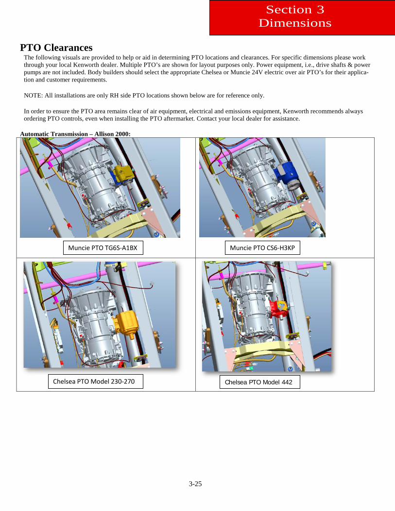
PTO Clearances
The following visuals are provided to help or aid in determining PTO locations and clearances. For specific dimensions please work through your local Kenworth dealer. Multiple PTO’s are shown for layout purposes only. Power equipment, i.e., drive shafts & power pumps are not included. Body builders should select the appropriate Chelsea or Muncie 24V electric over air PTO’s for their applica-tion and customer requirements. NOTE: All installations are only RH side PTO locations shown below are for reference only. In order to ensure the PTO area remains clear of air equipment, electrical and emissions equipment, Kenworth recommends always ordering PTO controls, even when installing the PTO aftermarket. Contact your local dealer for assistance.
Automatic Transmission – Allison 2000:
Section 3 Dimensions
Muncie PTO TG6S-A1BX
Chelsea PTO Model 442 Chelsea PTO Model 230-270
Muncie PTO CS6-H3KP
3-26
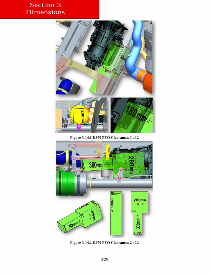
Figure 3-14.1 K370 PTO Clearances 1 of 2
Figure 3-14.2 K370 PTO Clearances 2 of 2
Section 3 Dimensions
3-27
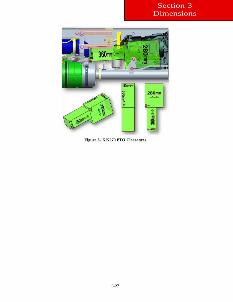
Figure 3-15 K270 PTO Clearances
Section 3 Dimensions
4-1
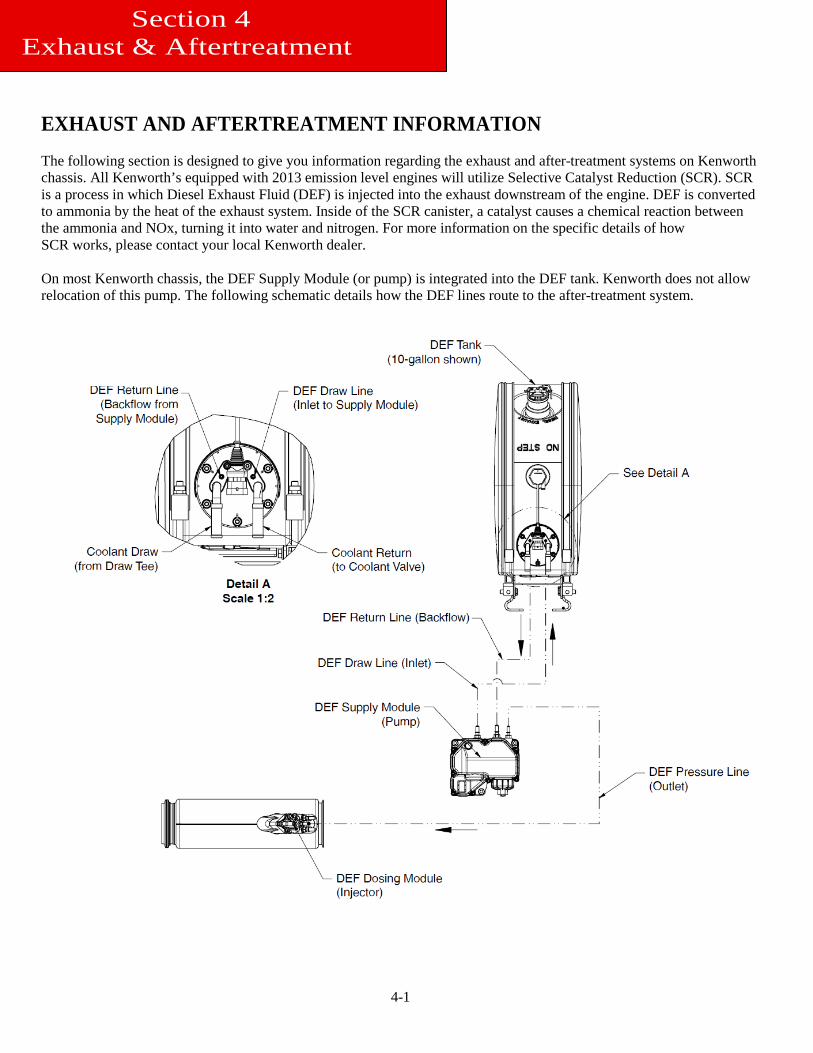
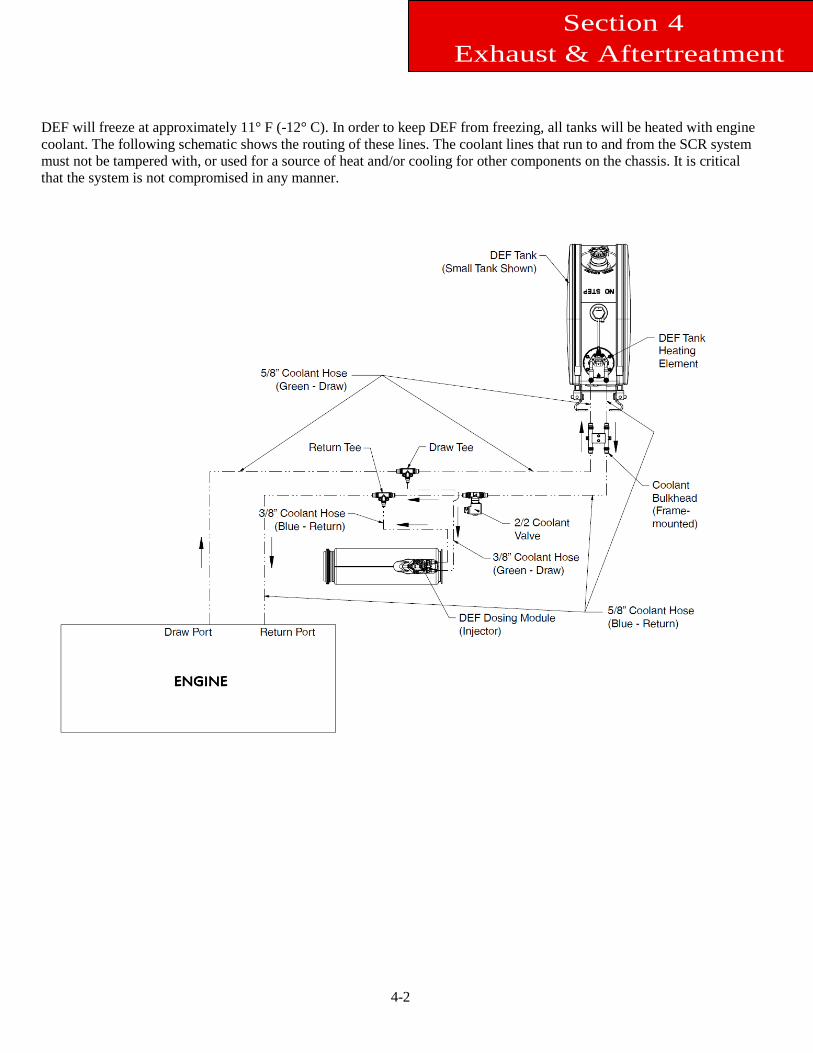
EXHAUST AND AFTERTREATMENT INFORMATION The following section is designed to give you information regarding the exhaust and after-treatment systems on Kenworth chassis. All Kenworth’s equipped with 2013 emission level engines will utilize Selective Catalyst Reduction (SCR). SCR is a process in which Diesel Exhaust Fluid (DEF) is injected into the exhaust downstream of the engine. DEF is converted to ammonia by the heat of the exhaust system. Inside of the SCR canister, a catalyst causes a chemical reaction between the ammonia and NOx, turning it into water and nitrogen. For more information on the specific details of how SCR works, please contact your local Kenworth dealer. On most Kenworth chassis, the DEF Supply Module (or pump) is integrated into the DEF tank. Kenworth does not allow relocation of this pump. The following schematic details how the DEF lines route to the after-treatment system.
Section 4 Exhaust & Aftertreatment
4-2
Section 4 Exhaust & Aftertreatment
DEF will freeze at approximately 11° F (-12° C). In order to keep DEF from freezing, all tanks will be heated with engine coolant. The following schematic shows the routing of these lines. The coolant lines that run to and from the SCR system must not be tampered with, or used for a source of heat and/or cooling for other components on the chassis. It is critical that the system is not compromised in any manner.
4-3
General Guidelines for DEF System The installation of the DEF tank is a critical component of the SCR system. While Kenworth does not recommend relocat-ing the DEF tank, there are applications and body installations that will require it. The guidelines below must be strictly followed by any entity relocating the tank. Failure to follow the guidelines completely and accurately may result in engine shutdown situations. Kenworth offers a variety of DEF tank sizes to meet every application. The DEF tank volume is regulated by the E.P.A. Kenworth advises against modifying the tank volume after the truck has been delivered from the factory.
•Total DEF capacity must meet or exceed 6% of the useable fuel capacity on the truck. The calculation to determine DEF capacity is: Minimum DEF Tank Volume = Useable Fuel Capacity (gal) x 0.06. Example: For a truck with 45 useable gallons of fuel, the equation is: DEF required = 45 x 0.06 = 2.7 gallons or more of DEF.
PACCAR-approved DEF hoses are required when retrofitting for system to function properly. The use of unapproved hoses for DEF lines will void warranty and may cause engine shutdown situations. The DEF pump (or Supply Module) cannot be relocated from the DEF tank. In addition, the Medium Duty Rectangular DEF Tank that is used to meet clear back of cab requirements cannot be relocated. Installation Requirements and Dimensions for DEF System When relocating any DEF system components, the locations must meet the guidelines below. Failure to comply may result in non-conformance to EPA standards and engine shutdown. DEF piping relative heights: In order to ensure proper functionality of DEF system, the height differences in the guide-lines below must be followed during line routing and component placement. When relocating the components the maximum pressure DEF hose length from Supply module to Dosing Module is 3 me-ters (118”). Maintain a minimum of 3” (76mm) clearance to shielded exhaust components when routing DEF lines to prevent possible melting. If the DEF tank is relocated, the coolant lines will need to be modified. During this process, if the tank is moved forward on the chassis (ie closer to the engine), it is necessary to remove excess coolant lines and maintain the original routing path. If the tank is moved rearward on the chassis, the additional length of the cooling line required to complete the installation must be installed in a straight section of the existing coolant routing lines. This process will minimize the change in coolant flow by minimizing changes in restrictions. Increase in restriction occurs with excessive line length and bends. Work with your local Kenworth dealer if you are unsure about the coolant line modifications.
Section 4 Exhaust & Aftertreatment
4-4
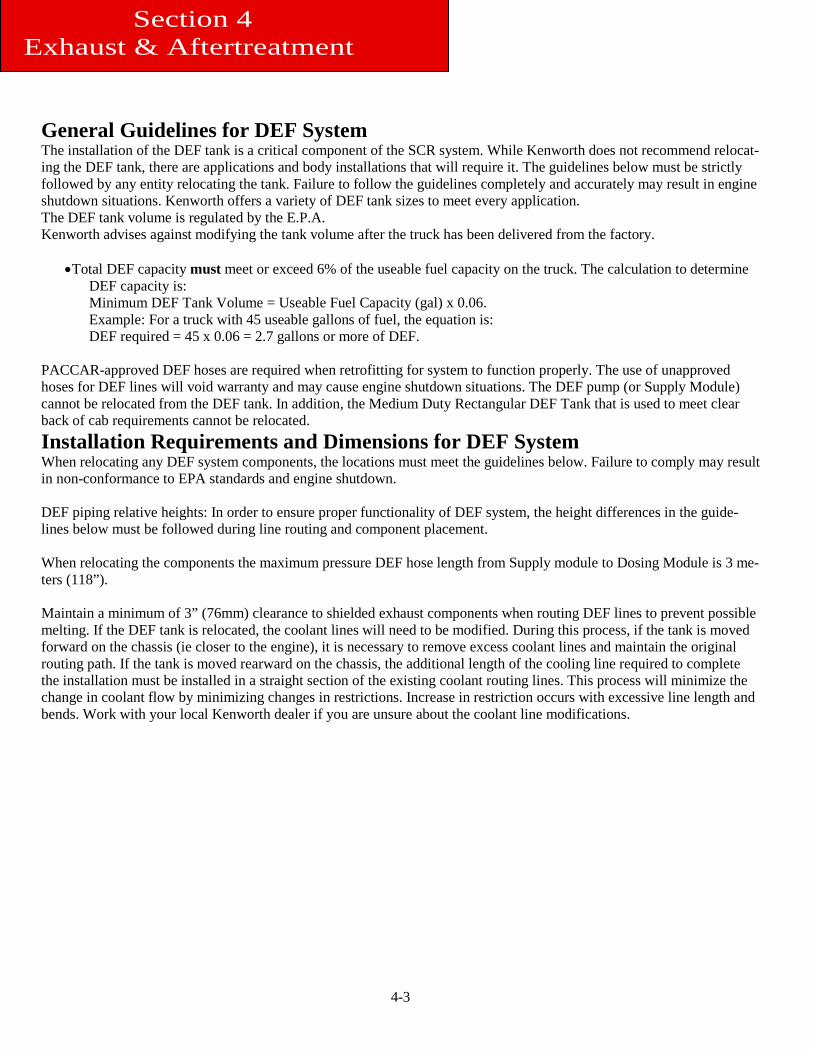
Measurement Reference Points For all relocation procedures, the measurement points referenced in the guidelines are taken from the following specific points: Supply Module: The supply module is commonly called a pump. The measurement point on the supply module is the top of the DEF fluid pressure line. See Figure 4-1.
Figure 4-1: Measurement Location of DEF Supply Module (Pump)
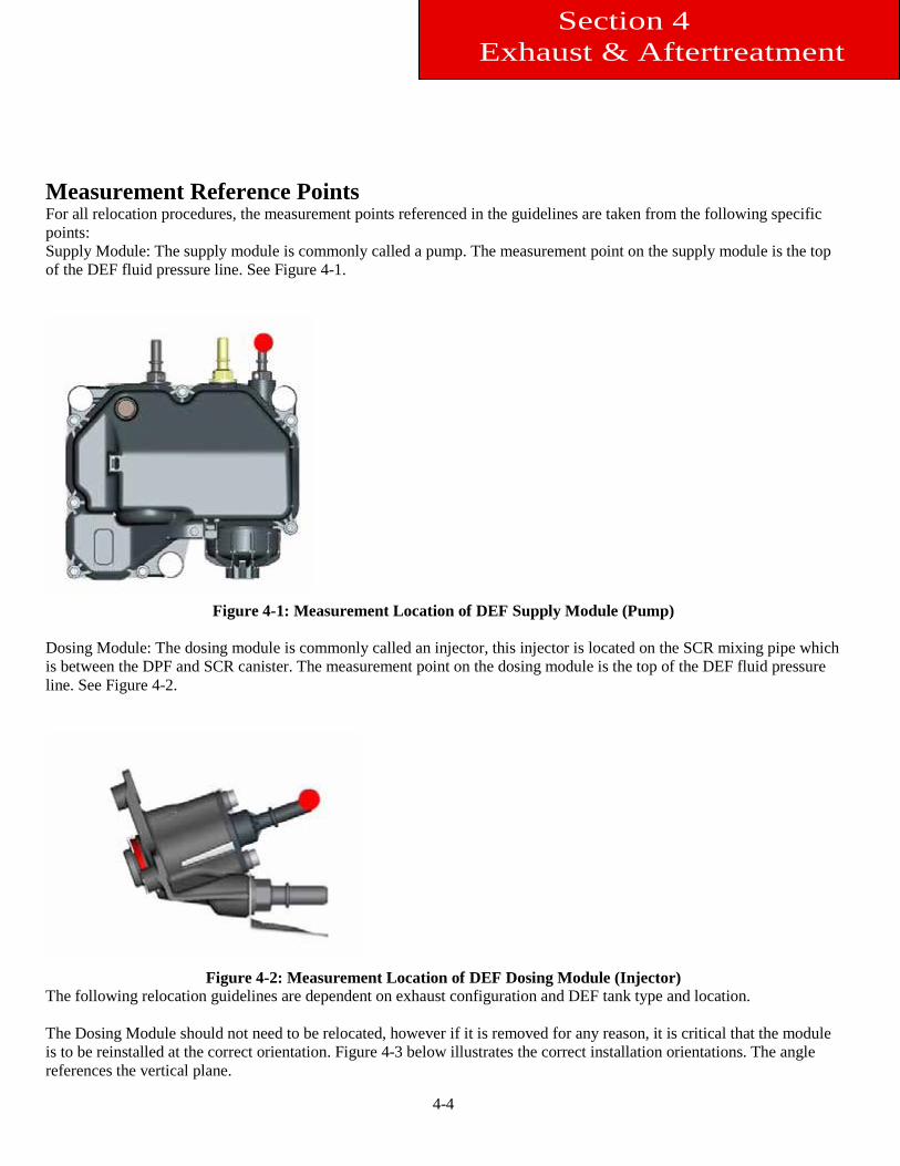
Dosing Module: The dosing module is commonly called an injector, this injector is located on the SCR mixing pipe which is between the DPF and SCR canister. The measurement point on the dosing module is the top of the DEF fluid pressure line. See Figure 4-2.
Figure 4-2: Measurement Location of DEF Dosing Module (Injector)
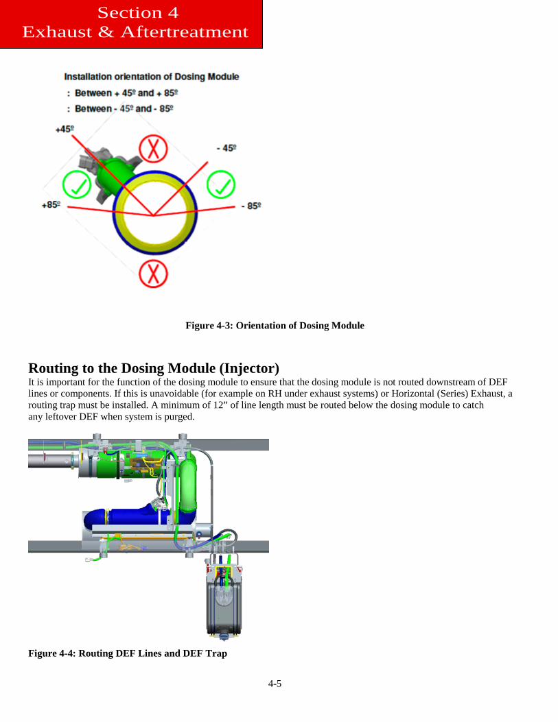
The following relocation guidelines are dependent on exhaust configuration and DEF tank type and location. The Dosing Module should not need to be relocated, however if it is removed for any reason, it is critical that the module is to be reinstalled at the correct orientation. Figure 4-3 below illustrates the correct installation orientations. The angle references the vertical plane.
Section 4 Exhaust & Aftertreatment
4-5
Figure 4-3: Orientation of Dosing Module Routing to the Dosing Module (Injector) It is important for the function of the dosing module to ensure that the dosing module is not routed downstream of DEF lines or components. If this is unavoidable (for example on RH under exhaust systems) or Horizontal (Series) Exhaust, a routing trap must be installed. A minimum of 12” of line length must be routed below the dosing module to catch any leftover DEF when system is purged.
Figure 4-4: Routing DEF Lines and DEF Trap
Section 4 Exhaust & Aftertreatment
4-6
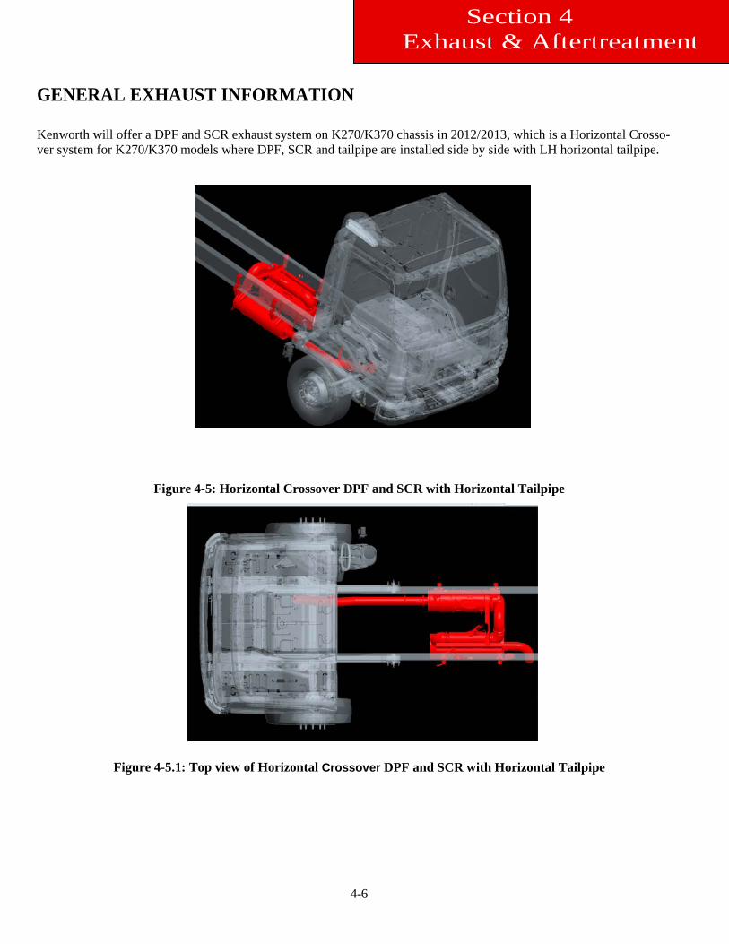
GENERAL EXHAUST INFORMATION Kenworth will offer a DPF and SCR exhaust system on K270/K370 chassis in 2012/2013, which is a Horizontal Crosso-ver system for K270/K370 models where DPF, SCR and tailpipe are installed side by side with LH horizontal tailpipe.
Figure 4-5: Horizontal Crossover DPF and SCR with Horizontal Tailpipe
Figure 4-5.1: Top view of Horizontal Crossover DPF and SCR with Horizontal Tailpipe
Section 4 Exhaust & Aftertreatment
4-7
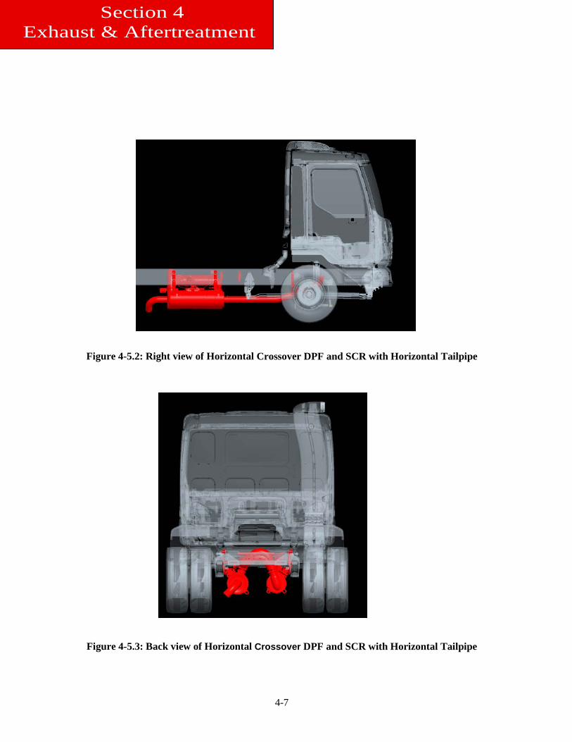
Figure 4-5.2: Right view of Horizontal Crossover DPF and SCR with Horizontal Tailpipe
Figure 4-5.3: Back view of Horizontal Crossover DPF and SCR with Horizontal Tailpipe
Section 4 Exhaust & Aftertreatment
5-1
Section 5 Frame Layouts and
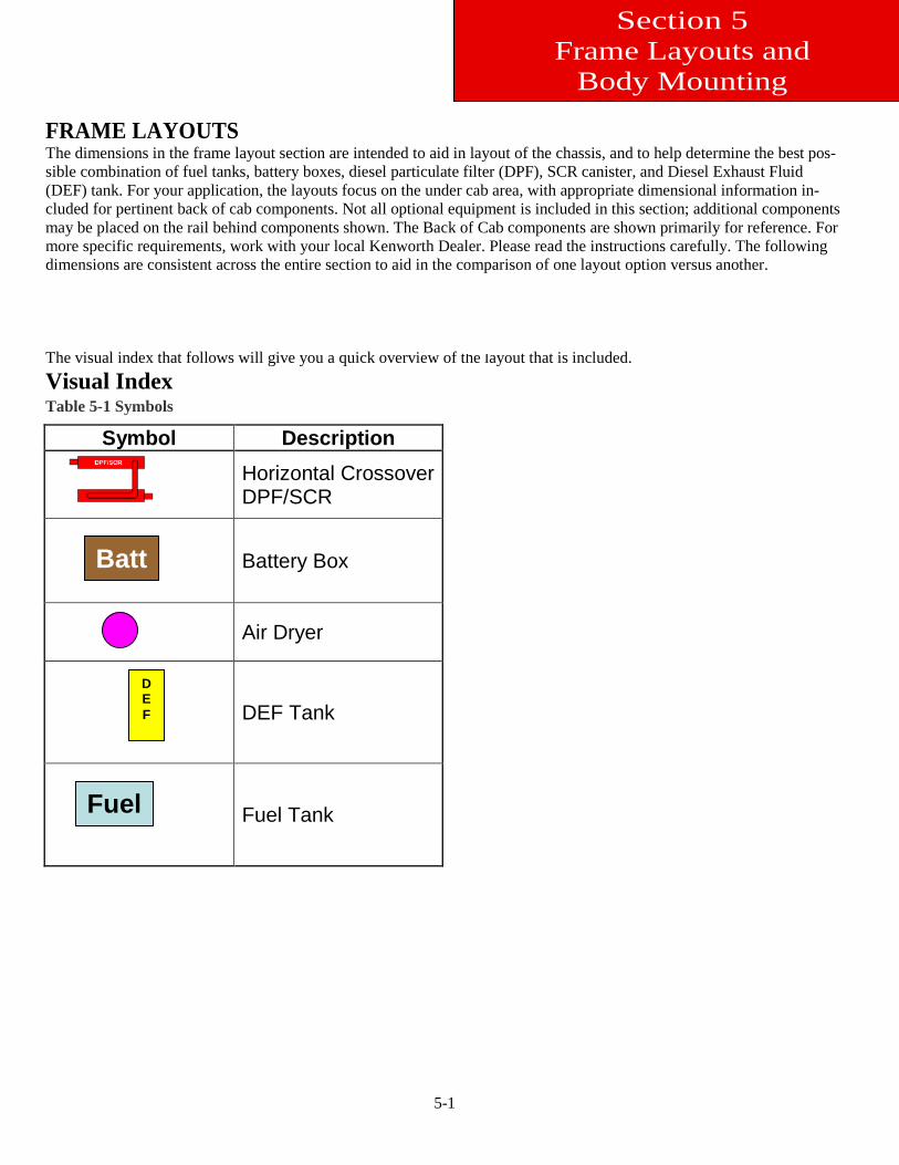
Body Mounting FRAME LAYOUTS The dimensions in the frame layout section are intended to aid in layout of the chassis, and to help determine the best pos-sible combination of fuel tanks, battery boxes, diesel particulate filter (DPF), SCR canister, and Diesel Exhaust Fluid (DEF) tank. For your application, the layouts focus on the under cab area, with appropriate dimensional information in-cluded for pertinent back of cab components. Not all optional equipment is included in this section; additional components may be placed on the rail behind components shown. The Back of Cab components are shown primarily for reference. For more specific requirements, work with your local Kenworth Dealer. Please read the instructions carefully. The following dimensions are consistent across the entire section to aid in the comparison of one layout option versus another. The visual index that follows will give you a quick overview of the layout that is included. Visual Index Table 5-1 Symbols
Symbol Description
Horizontal Crossover DPF/SCR
Battery Box
Air Dryer
DEF Tank
Fuel Tank
Batt
DEF
Fuel
5-2
Section 5 Frame Layouts and Body
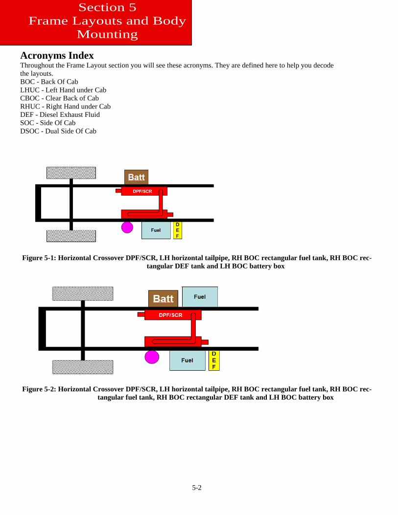
Mounting Acronyms Index Throughout the Frame Layout section you will see these acronyms. They are defined here to help you decode the layouts. BOC - Back Of Cab LHUC - Left Hand under Cab CBOC - Clear Back of Cab RHUC - Right Hand under Cab DEF - Diesel Exhaust Fluid SOC - Side Of Cab DSOC - Dual Side Of Cab
Figure 5-1: Horizontal Crossover DPF/SCR, LH horizontal tailpipe, RH BOC rectangular fuel tank, RH BOC rec-
tangular DEF tank and LH BOC battery box
Figure 5-2: Horizontal Crossover DPF/SCR, LH horizontal tailpipe, RH BOC rectangular fuel tank, RH BOC rec-
tangular fuel tank, RH BOC rectangular DEF tank and LH BOC battery box
5-3
Section 5 Frame Layouts and
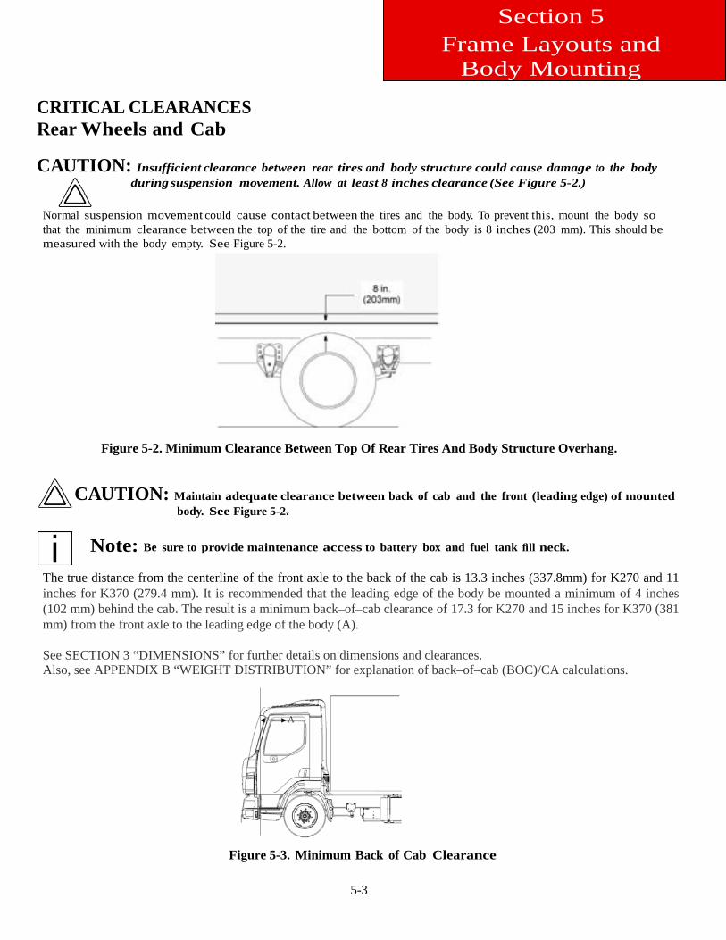
Body Mounting CRITICAL CLEARANCES Rear Wheels and Cab CAUTION: Insufficient clearance between rear tires and body structure could cause damage to the body
during suspension movement. Allow at least 8 inches clearance (See Figure 5-2.)
Normal suspension movement could cause contact between the tires and the body. To prevent this, mount the body so that the minimum clearance between the top of the tire and the bottom of the body is 8 inches (203 mm). This should be measured with the body empty. See Figure 5-2.
Figure 5-2. Minimum Clearance Between Top Of Rear Tires And Body Structure Overhang.
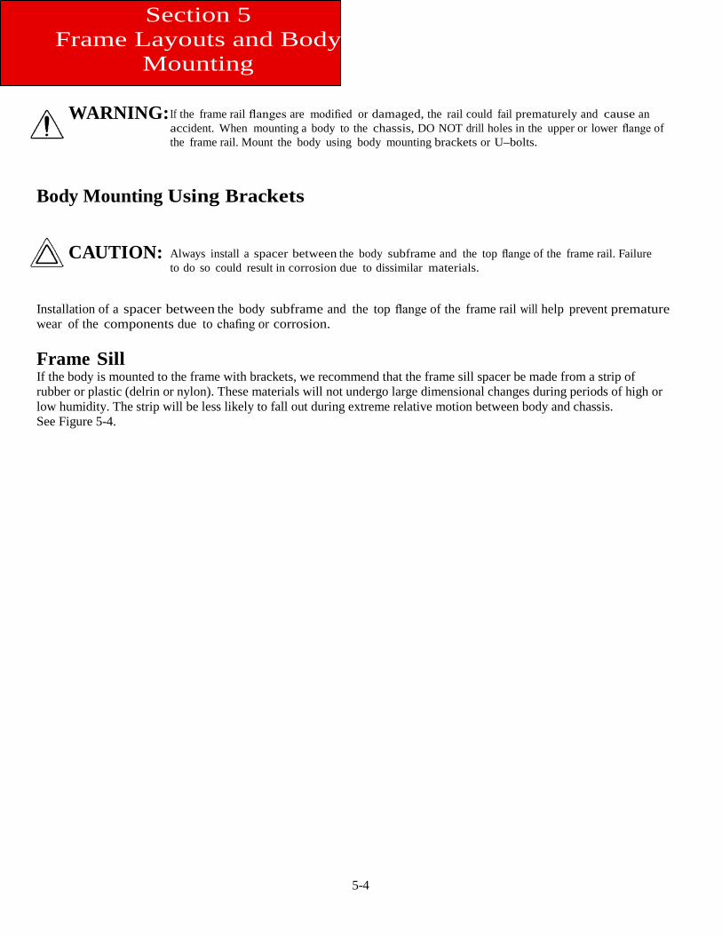
CAUTION: Maintain adequate clearance between back of cab and the front (leading edge) of mounted body. See Figure 5-2.
Note: Be sure to provide maintenance access to battery box and fuel tank fill neck.
The true distance from the centerline of the front axle to the back of the cab is 13.3 inches (337.8mm) for K270 and 11 inches for K370 (279.4 mm). It is recommended that the leading edge of the body be mounted a minimum of 4 inches (102 mm) behind the cab. The result is a minimum back–of–cab clearance of 17.3 for K270 and 15 inches for K370 (381 mm) from the front axle to the leading edge of the body (A). See SECTION 3 “DIMENSIONS” for further details on dimensions and clearances. Also, see APPENDIX B “WEIGHT DISTRIBUTION” for explanation of back–of–cab (BOC)/CA calculations.
A
Figure 5-3. Minimum Back of Cab Clearance
5-4
Section 5 Frame Layouts and Body
Mounting
WARNING:
If the frame rail flanges are modified or damaged, the rail could fail prematurely and cause an accident. When mounting a body to the chassis, DO NOT drill holes in the upper or lower flange of the frame rail. Mount the body using body mounting brackets or U–bolts.
Body Mounting Using Brackets
CAUTION:
Always install a spacer between the body subframe and the top flange of the frame rail. Failure to do so could result in corrosion due to dissimilar materials.
Installation of a spacer between the body subframe and the top flange of the frame rail will help prevent premature wear of the components due to chafing or corrosion. Frame Sill If the body is mounted to the frame with brackets, we recommend that the frame sill spacer be made from a strip of rubber or plastic (delrin or nylon). These materials will not undergo large dimensional changes during periods of high or low humidity. The strip will be less likely to fall out during extreme relative motion between body and chassis. See Figure 5-4.
5-5
Section 5 Frame Layouts and Body
Mounting
Body Subframe (Rail)
Chassis Frame (Rail) Sill
Spacer
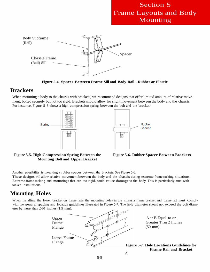
Figure 5-4. Spacer Between Frame Sill and Body Rail - Rubber or Plastic
Brackets When mounting a body to the chassis with brackets, we recommend designs that offer limited amount of relative move-ment, bolted securely but not too rigid. Brackets should allow for slight movement between the body and the chassis. For instance, Figure 5–5 shows a high compression spring between the bolt and the bracket.
Figure 5-5. High Compression Spring Between the Mounting Bolt and Upper Bracket
Figure 5-6. Rubber Spacer Between Brackets
Another possibility is mounting a rubber spacer between the brackets. See Figure 5-6. These designs will allow relative movement between the body and the chassis during extreme frame racking situations. Extreme frame racking and mountings that are too rigid, could cause damage to the body. This is particularly true with tanker installations.
Mounting Holes
When installing the lower bracket on frame rails the mounting holes in the chassis frame bracket and frame rail must comply with the general spacing and location guidelines illustrated in Figure 5-7. The hole diameter should not exceed the bolt diam-eter by more than .060 inches (1.5 mm).
Upper Frame Flange
Lower Frame Flange
A
A or B Equal to or Greater Than 2 Inches (50 mm)
Figure 5-7. Hole Locations Guidelines for Frame Rail and Bracket
5-6
Section 5 Frame Layouts and Body
Mounting
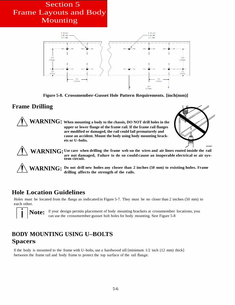
Figure 5-8. Crossmember-Gusset Hole Pattern Requirements. [inch(mm)] Frame Drilling
WARNING: When mounting a body to the chassis, DO NOT drill holes in the upper or lower flange of the frame rail. If the frame rail flanges are modified or damaged, the rail could fail prematurely and cause an accident. Mount the body using body mounting brack-ets or U–bolts.
WARNING: Use care when drilling the frame web so the wires and air lines routed inside the rail
are not damaged, Failure to do so could cause an inoperable electrical or air sys-tem circuit.
WARNING: Do not drill new holes any closer than 2 inches (50 mm) to existing holes. Frame drilling affects the strength of the rails.
Hole Location Guidelines Holes must be located from the flange as indicated in Figure 5-7. They must be no closer than 2 inches (50 mm) to each other.
Note: If your design permits placement of body mounting brackets at crossmember locations, you can use the crossmember gusset bolt holes for body mounting. See Figure 5-8
BODY MOUNTING USING U–BOLTS Spacers
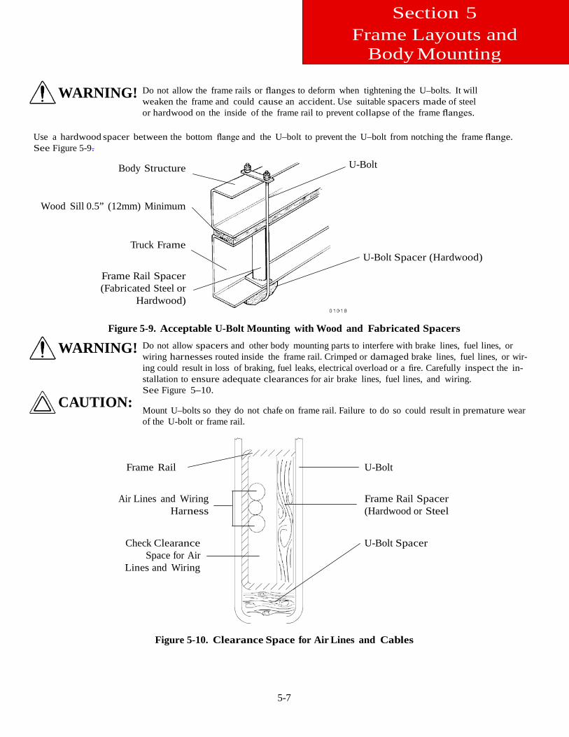
If the body is mounted to the frame with U–bolts, use a hardwood sill [minimum 1/2 inch (12 mm) thick] between the frame rail and body frame to protect the top surface of the rail flange.
5-7
Section 5 Frame Layouts and
Body Mounting
WARNING! Do not allow the frame rails or flanges to deform when tightening the U–bolts. It will weaken the frame and could cause an accident. Use suitable spacers made of steel or hardwood on the inside of the frame rail to prevent collapse of the frame flanges.
Use a hardwood spacer between the bottom flange and the U–bolt to prevent the U–bolt from notching the frame flange. See Figure 5-9.
Body Structure
Wood Sill 0.5” (12mm) Minimum
Truck Frame
Frame Rail Spacer (Fabricated Steel or
Hardwood)
U-Bolt
U-Bolt Spacer (Hardwood)
Figure 5-9. Acceptable U-Bolt Mounting with Wood and Fabricated Spacers
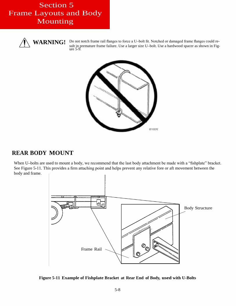
WARNING!
CAUTION:
Do not allow spacers and other body mounting parts to interfere with brake lines, fuel lines, or wiring harnesses routed inside the frame rail. Crimped or damaged brake lines, fuel lines, or wir-ing could result in loss of braking, fuel leaks, electrical overload or a fire. Carefully inspect the in-stallation to ensure adequate clearances for air brake lines, fuel lines, and wiring. See Figure 5–10.
Mount U–bolts so they do not chafe on frame rail. Failure to do so could result in premature wear of the U-bolt or frame rail.
Frame Rail
Air Lines and Wiring Harness
Check Clearance Space for Air
Lines and Wiring
U-Bolt Frame Rail Spacer (Hardwood or Steel U-Bolt Spacer
Figure 5-10. Clearance Space for Air Lines and Cables
5-8
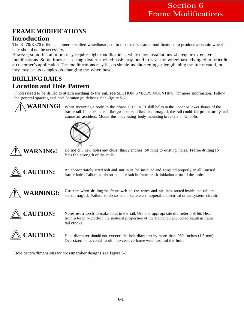
WARNING! Do not notch frame rail flanges to force a U–bolt fit. Notched or damaged frame flanges could re-sult in premature frame failure. Use a larger size U–bolt. Use a hardwood spacer as shown in Fig-ure 5-9.
REAR BODY MOUNT When U–bolts are used to mount a body, we recommend that the last body attachment be made with a “fishplate” bracket. See Figure 5-11. This provides a firm attaching point and helps prevent any relative fore or aft movement between the body and frame.
Body Structure
Frame Rail
Figure 5-11 Example of Fishplate Bracket at Rear End of Body, used with U-Bolts
Section 5 Frame Layouts and Body
Mounting
6-1
Section 6 Frame Modifications
FRAME MODIFICATIONS Introduction The K270/K370 offers customer specified wheelbases, so, in most cases frame modifications to produce a certain wheel-base should not be necessary. However, some installations may require slight modifications, while other installations will require extensive modifications. Sometimes an existing dealer stock chassis may need to have the wheelbase changed to better fit a customer’s application. The modifications may be as simple as shortening or lengthening the frame cutoff, or they may be as complex as changing the wheelbase.
DRILLING RAILS Location and Hole Pattern
If holes need to be drilled to attach anything to the rail, see SECTION 5 “BODY MOUNTING” for more information. Follow the general spacing and hole location guidelines. See Figure 5-7.
WARNING!
WARNING!
CAUTION:
WARNING!:
CAUTION:
CAUTION:
When mounting a body to the chassis, DO NOT drill holes in the upper or lower flange of the frame rail. If the frame rail flanges are modified or damaged, the rail could fail prematurely and cause an accident. Mount the body using body mounting brackets or U–bolts
Do not drill new holes any closer than 2 inches (50 mm) to existing holes. Frame drilling af-fects the strength of the rails.
An appropriately sized bolt and nut must be installed and torqued properly in all unused frame holes. Failure to do so could result in frame crack initiation around the hole. Use care when drilling the frame web so the wires and air lines routed inside the rail are not damaged, Failure to do so could cause an inoperable electrical or air system circuit. Never use a torch to make holes in the rail. Use the appropriate diameter drill bit. Heat from a torch will affect the material properties of the frame rail and could result in frame rail cracks. Hole diameter should not exceed the bolt diameter by more than .060 inches (1.5 mm). Oversized holes could result in excessive frame wear around the hole.
Hole pattern dimensions for crossmember designs see Figure 5-8
6-2
Section 6 Frame Modifications
MODIFYING FRAME LENGTH The frame cutoff after the rear axle can be shortened to match a particular body length. Using a torch is acceptable; however, heat from a torch will affect the material characteristics of the frame rail. The affected material will normally be confined to with-in 1 to 2 inches (25 to 50 mm) of the flame cut and may not adversely affect the strength of the chassis or body installation. The frame cutoff can be lengthened by adding frame extenders.
WARNING! Do not drill new holes any closer than 2 inches (50 mm) to existing holes. Frame drilling af-fects the strength of the rails.
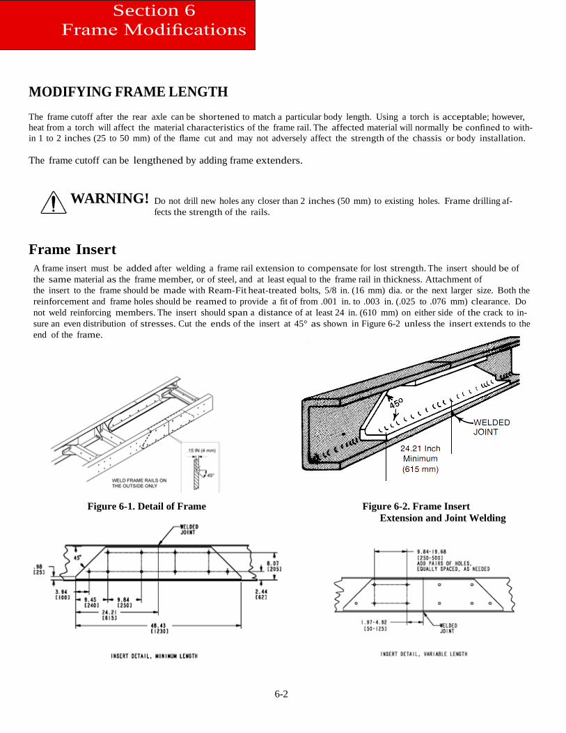
Frame Insert
A frame insert must be added after welding a frame rail extension to compensate for lost strength. The insert should be of the same material as the frame member, or of steel, and at least equal to the frame rail in thickness. Attachment of the insert to the frame should be made with Ream-Fit heat-treated bolts, 5/8 in. (16 mm) dia. or the next larger size. Both the reinforcement and frame holes should be reamed to provide a fit of from .001 in. to .003 in. (.025 to .076 mm) clearance. Do not weld reinforcing members. The insert should span a distance of at least 24 in. (610 mm) on either side of the crack to in-sure an even distribution of stresses. Cut the ends of the insert at 45° as shown in Figure 6-2 unless the insert extends to the end of the frame.
Figure 6-1. Detail of Frame Figure 6-2. Frame Insert Extension and Joint Welding
6-3
Section 6 Frame Modifications
Where possible, use existing bolt holes to attach the insert to the frame. Bolt holes must not be located closer to the frame flanges than the present bolt pattern.
If the insert is placed in a section of the main frame where few bolts are located, additional bolts are required. Use the following guideline for locating additional bolt holes.
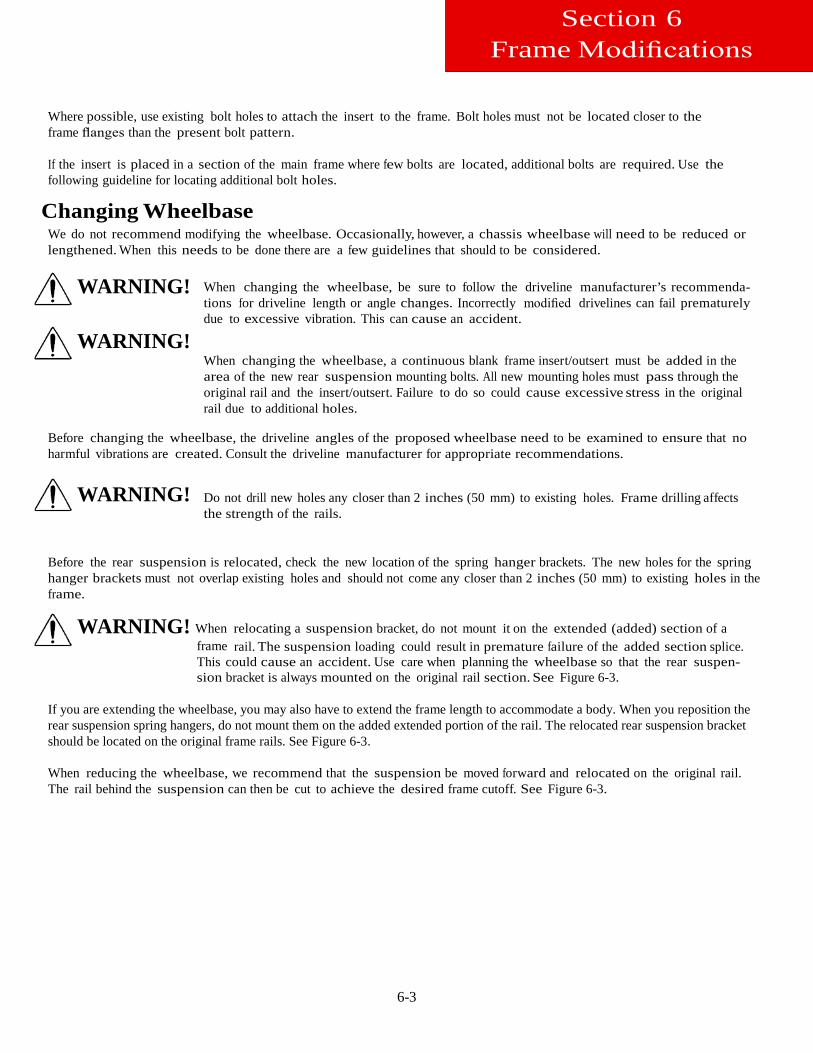
Changing Wheelbase We do not recommend modifying the wheelbase. Occasionally, however, a chassis wheelbase will need to be reduced or lengthened. When this needs to be done there are a few guidelines that should to be considered.
WARNING!
WARNING!
When changing the wheelbase, be sure to follow the driveline manufacturer’s recommenda-tions for driveline length or angle changes. Incorrectly modified drivelines can fail prematurely due to excessive vibration. This can cause an accident.
When changing the wheelbase, a continuous blank frame insert/outsert must be added in the area of the new rear suspension mounting bolts. All new mounting holes must pass through the original rail and the insert/outsert. Failure to do so could cause excessive stress in the original rail due to additional holes.
Before changing the wheelbase, the driveline angles of the proposed wheelbase need to be examined to ensure that no harmful vibrations are created. Consult the driveline manufacturer for appropriate recommendations.
WARNING!
Do not drill new holes any closer than 2 inches (50 mm) to existing holes. Frame drilling affects the strength of the rails.
Before the rear suspension is relocated, check the new location of the spring hanger brackets. The new holes for the spring hanger brackets must not overlap existing holes and should not come any closer than 2 inches (50 mm) to existing holes in the frame.
WARNING! When relocating a suspension bracket, do not mount it on the extended (added) section of a frame rail. The suspension loading could result in premature failure of the added section splice. This could cause an accident. Use care when planning the wheelbase so that the rear suspen-sion bracket is always mounted on the original rail section. See Figure 6-3.
If you are extending the wheelbase, you may also have to extend the frame length to accommodate a body. When you reposition the rear suspension spring hangers, do not mount them on the added extended portion of the rail. The relocated rear suspension bracket should be located on the original frame rails. See Figure 6-3.
When reducing the wheelbase, we recommend that the suspension be moved forward and relocated on the original rail. The rail behind the suspension can then be cut to achieve the desired frame cutoff. See Figure 6-3.
6-4
Section 6 Frame Modifications
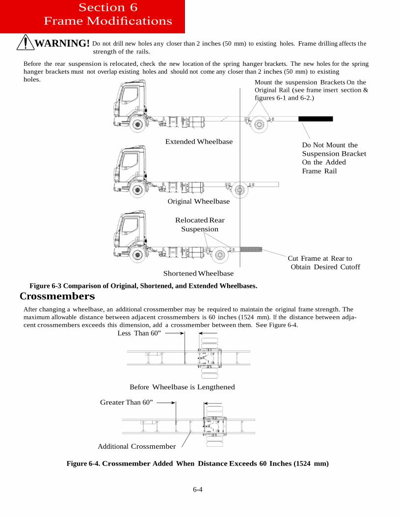
WARNING! Do not drill new holes any closer than 2 inches (50 mm) to existing holes. Frame drilling affects the
strength of the rails.
Before the rear suspension is relocated, check the new location of the spring hanger brackets. The new holes for the spring hanger brackets must not overlap existing holes and should not come any closer than 2 inches (50 mm) to existing holes. Mount the suspension Brackets On the
Original Rail (see frame insert section & figures 6-1 and 6-2.)
Extended Wheelbase
Do Not Mount the Suspension Bracket On the Added Frame Rail
Original Wheelbase
Relocated Rear
Suspension
Shortened Wheelbase
Figure 6-3 Comparison of Original, Shortened, and Extended Wheelbases. Crossmembers
Cut Frame at Rear to Obtain Desired Cutoff
After changing a wheelbase, an additional crossmember may be required to maintain the original frame strength. The maximum allowable distance between adjacent crossmembers is 60 inches (1524 mm). If the distance between adja-cent crossmembers exceeds this dimension, add a crossmember between them. See Figure 6-4.
Less Than 60”
Before Wheelbase is Lengthened
Greater Than 60”
Additional Crossmember
Figure 6-4. Crossmember Added When Distance Exceeds 60 Inches (1524 mm)
7-1
ELECTRICAL Introduction
Electrical wiring can sometimes be very frustrating. This is especially true when adding circuits to an existing setup. Through the use of an optional body harness and additional spare circuits, we have tried to reduce the complexity as-sociated with adding common circuits to a body installation.
Note: The most common circuits that body builders may need are pre-connected to this optional wiring harness.
The new body related circuits can be added by connecting the added circuit wires to the appropriate wires in this harness.
ELECTRICAL CIRCUITS Capacity
WARNING! Do not install an electrical circuit that requires more amperage (electrical capacity) than what is available in the specific chassis circuit. An overloaded circuit could cause a fire. Compare the amperage requirements of the new circuit to the electrical current capacity of the existing chassis circuit before adding the body or other equipment.
When adding an electrical circuit, you must know the current capacity (amperes) of each circuit.
The capacity of the existing system in the chassis must be enough to power the additional circuit. The new circuit will require a certain amount of power to operate; so, the existing (battery or alternator) power source must have the capacity to provide addi-tional power or the new circuit will not function properly.
Check the current (ampere) demand of the circuit to be added. Compare it to the current capacity of the circuit you are connecting into. The current carrying capacity of the wires, controls, switches, and circuit breakers that provide current to the circuit must be equal to or greater than the demand of the added circuit otherwise these components may not work properly. See Table 7–1.1 and for relevant circuit information.
Section 7 Electrical
7-2
Dashboard Identification
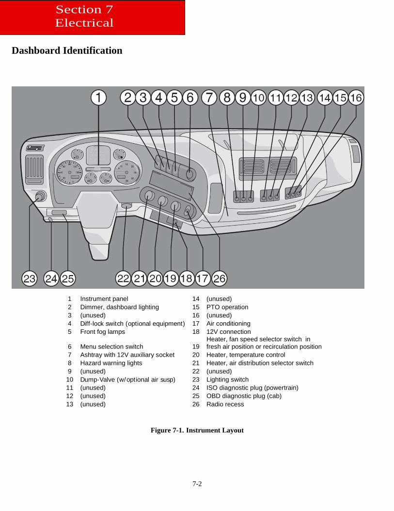
Figure 7-1. Instrument Layout
1 Instrument panel 14 (unused) 2 Dimmer, dashboard lighting 15 PTO operation 3 (unused) 16 (unused) 4 Diff-lock switch (optional equipment) 17 Air conditioning 5 Front fog lamps 18 12V connection
6 Menu selection switch 19 Heater, fan speed selector switch in fresh air position or recirculation position
7 Ashtray with 12V auxiliary socket 20 Heater, temperature control 8 Hazard warning lights 21 Heater, air distribution selector switch 9 (unused) 22 (unused) 10 Dump-Valve (w/optional air susp) 23 Lighting switch 11 (unused) 24 ISO diagnostic plug (powertrain) 12 (unused) 25 OBD diagnostic plug (cab) 13 (unused) 26 Radio recess
Section 7 Electrical
7-3
Section 7 Electrical
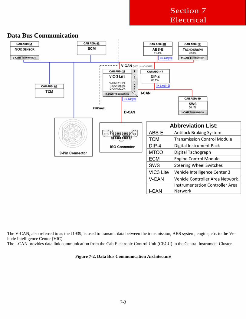
Data Bus Communication
The V-CAN, also referred to as the J1939, is used to transmit data between the transmission, ABS system, engine, etc. to the Ve-hicle Intelligence Center (VIC). The I-CAN provides data link communication from the Cab Electronic Control Unit (CECU) to the Central Instrument Cluster.
Figure 7-2. Data Bus Communication Architecture
Abbreviation List: ABS-E Antilock Braking System TCM Transmission Control Module DIP-4 Digital Instrument Pack MTCO Digital Tachograph ECM Engine Control Module SWS Steering Wheel Switches VIC3 Lite Vehicle Intelligence Center 3 V-CAN Vehicle Controller Area Network
I-CAN Instrumentation Controller Area Network
7-4
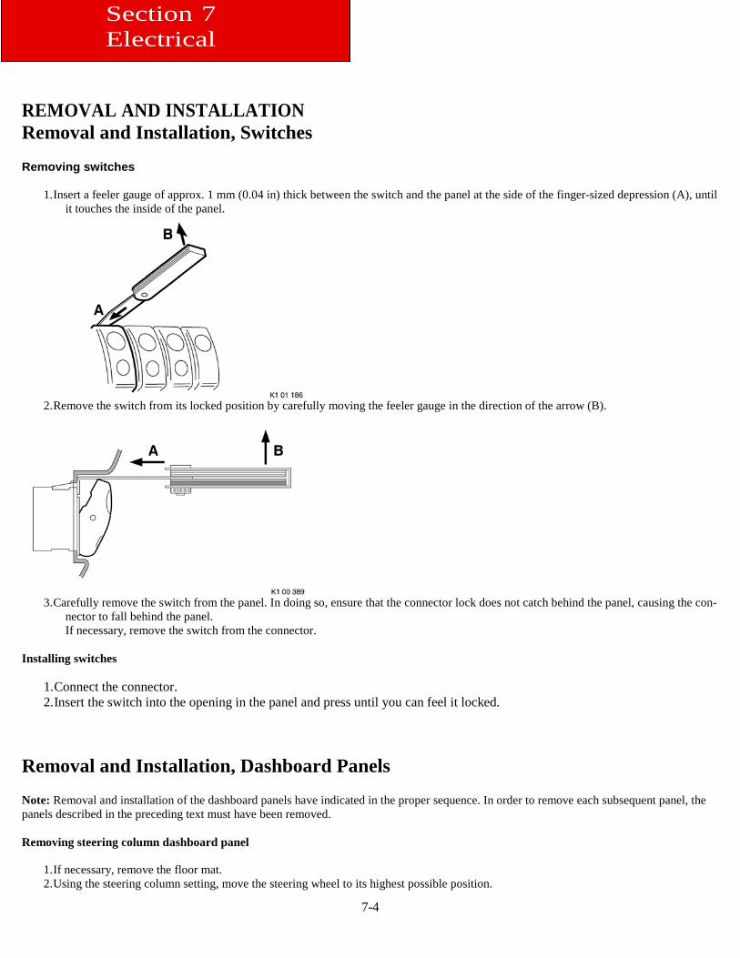
REMOVAL AND INSTALLATION Removal and Installation, Switches Removing switches
1. Insert a feeler gauge of approx. 1 mm (0.04 in) thick between the switch and the panel at the side of the finger-sized depression (A), until it touches the inside of the panel.
2. Remove the switch from its locked position by carefully moving the feeler gauge in the direction of the arrow (B).
3. Carefully remove the switch from the panel. In doing so, ensure that the connector lock does not catch behind the panel, causing the con-
nector to fall behind the panel. If necessary, remove the switch from the connector.
Installing switches
1. Connect the connector. 2. Insert the switch into the opening in the panel and press until you can feel it locked.
Removal and Installation, Dashboard Panels Note: Removal and installation of the dashboard panels have indicated in the proper sequence. In order to remove each subsequent panel, the panels described in the preceding text must have been removed. Removing steering column dashboard panel
1. If necessary, remove the floor mat. 2. Using the steering column setting, move the steering wheel to its highest possible position.
Section 7 Electrical
7-5
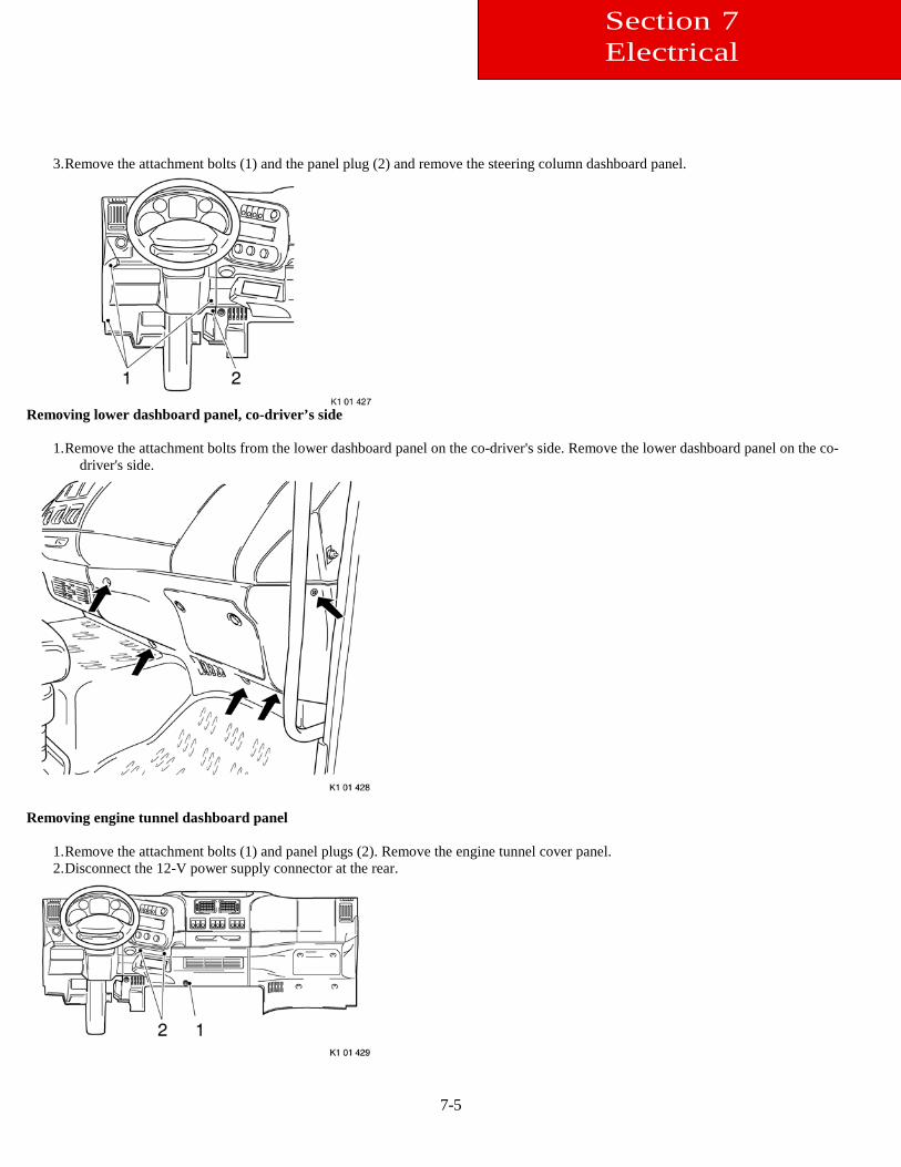
3. Remove the attachment bolts (1) and the panel plug (2) and remove the steering column dashboard panel.
Removing lower dashboard panel, co-driver’s side
1. Remove the attachment bolts from the lower dashboard panel on the co-driver's side. Remove the lower dashboard panel on the co-driver's side.
Removing engine tunnel dashboard panel
1. Remove the attachment bolts (1) and panel plugs (2). Remove the engine tunnel cover panel. 2. Disconnect the 12-V power supply connector at the rear.
Section 7 Electrical
7-6
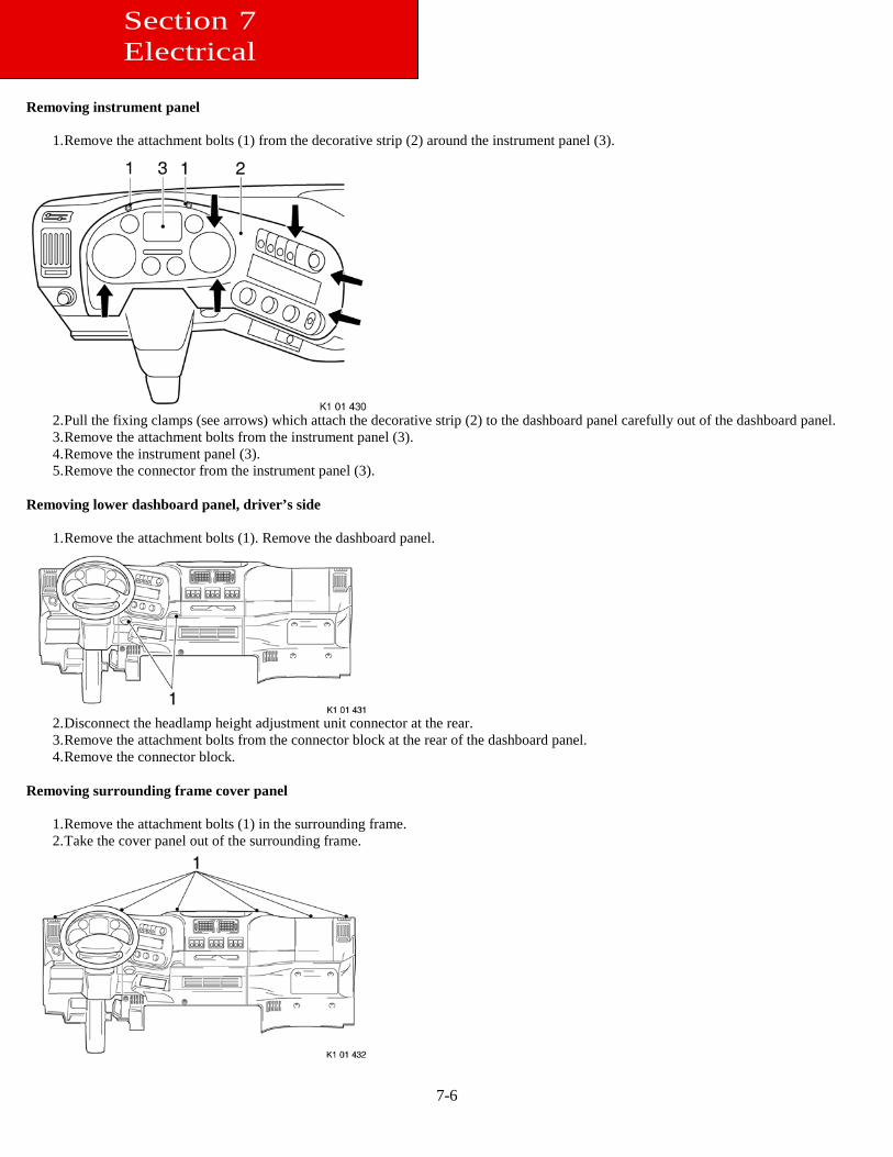
Removing instrument panel
1. Remove the attachment bolts (1) from the decorative strip (2) around the instrument panel (3).
2. Pull the fixing clamps (see arrows) which attach the decorative strip (2) to the dashboard panel carefully out of the dashboard panel. 3. Remove the attachment bolts from the instrument panel (3). 4. Remove the instrument panel (3). 5. Remove the connector from the instrument panel (3).
Removing lower dashboard panel, driver’s side
1. Remove the attachment bolts (1). Remove the dashboard panel.
2. Disconnect the headlamp height adjustment unit connector at the rear. 3. Remove the attachment bolts from the connector block at the rear of the dashboard panel. 4. Remove the connector block.
Removing surrounding frame cover panel
1. Remove the attachment bolts (1) in the surrounding frame. 2. Take the cover panel out of the surrounding frame.
Section 7 Electrical
7-7
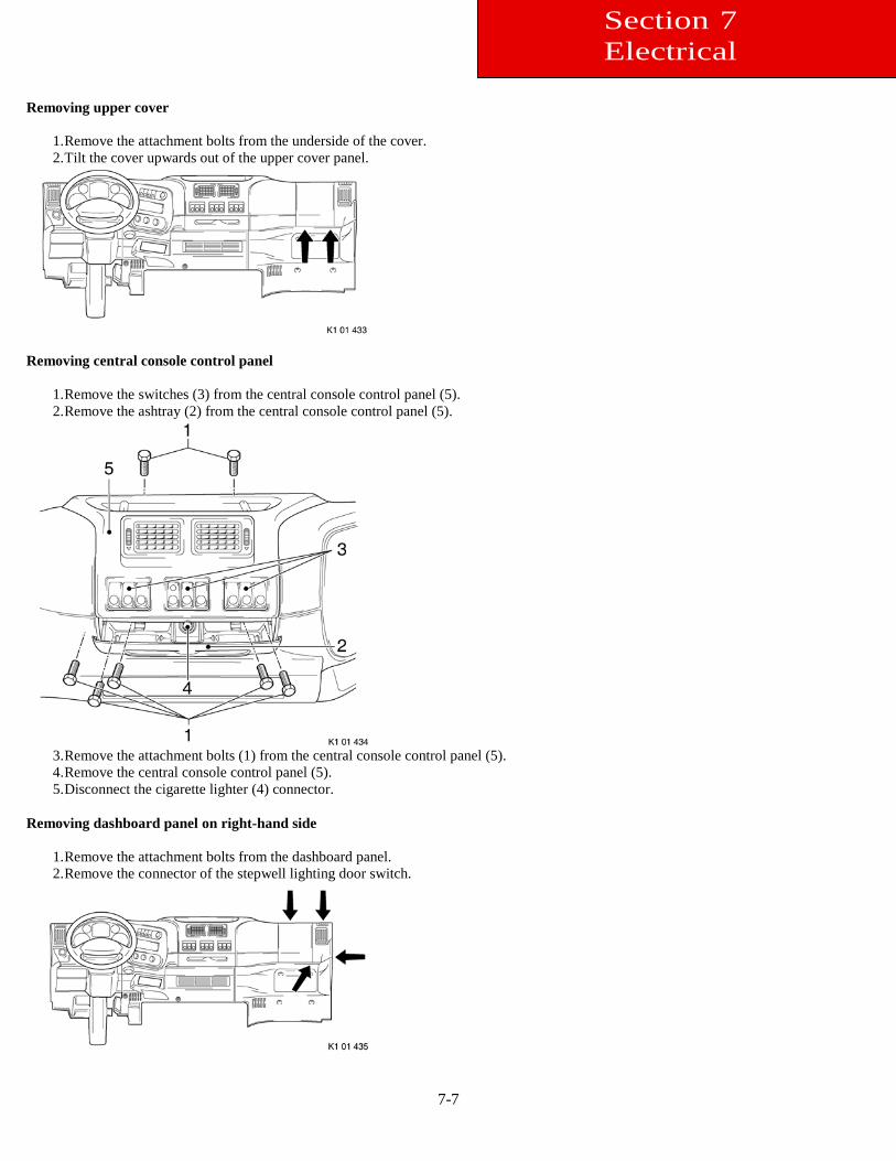
Removing upper cover
1. Remove the attachment bolts from the underside of the cover. 2. Tilt the cover upwards out of the upper cover panel.
Removing central console control panel
1. Remove the switches (3) from the central console control panel (5). 2. Remove the ashtray (2) from the central console control panel (5).
3. Remove the attachment bolts (1) from the central console control panel (5). 4. Remove the central console control panel (5). 5. Disconnect the cigarette lighter (4) connector.
Removing dashboard panel on right-hand side
1. Remove the attachment bolts from the dashboard panel. 2. Remove the connector of the stepwell lighting door switch.
Section 7 Electrical
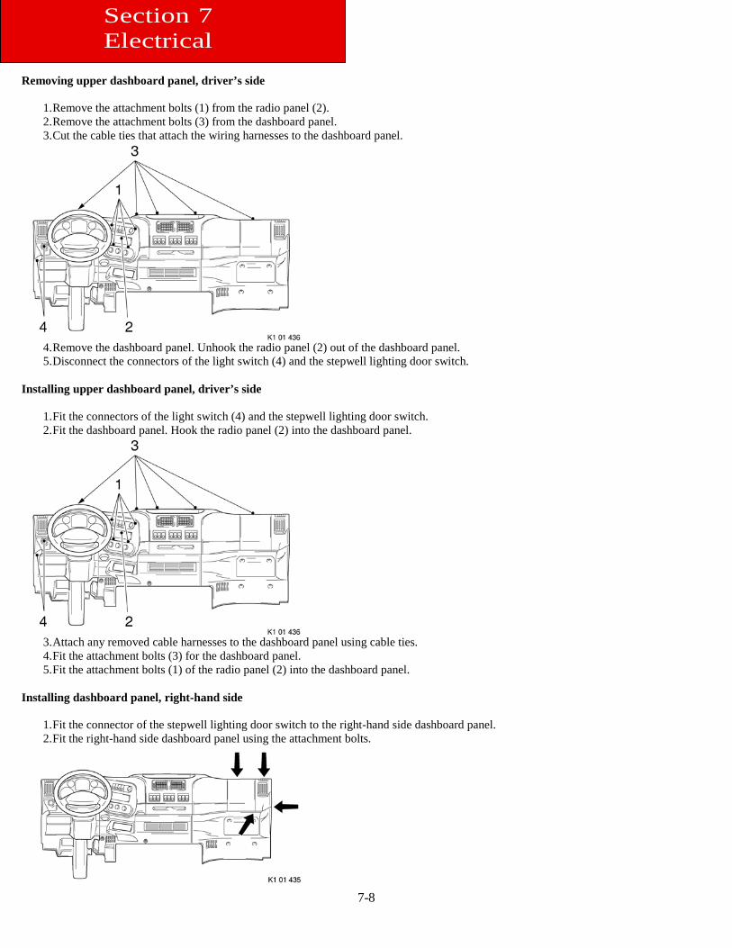
7-8
Removing upper dashboard panel, driver’s side
1. Remove the attachment bolts (1) from the radio panel (2). 2. Remove the attachment bolts (3) from the dashboard panel. 3. Cut the cable ties that attach the wiring harnesses to the dashboard panel.
4. Remove the dashboard panel. Unhook the radio panel (2) out of the dashboard panel. 5. Disconnect the connectors of the light switch (4) and the stepwell lighting door switch.
Installing upper dashboard panel, driver’s side
1. Fit the connectors of the light switch (4) and the stepwell lighting door switch. 2. Fit the dashboard panel. Hook the radio panel (2) into the dashboard panel.
3. Attach any removed cable harnesses to the dashboard panel using cable ties. 4. Fit the attachment bolts (3) for the dashboard panel. 5. Fit the attachment bolts (1) of the radio panel (2) into the dashboard panel.
Installing dashboard panel, right-hand side
1. Fit the connector of the stepwell lighting door switch to the right-hand side dashboard panel. 2. Fit the right-hand side dashboard panel using the attachment bolts.
Section 7 Electrical
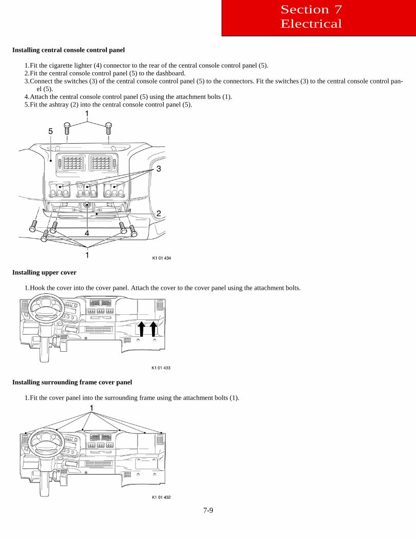
7-9
Installing central console control panel
1. Fit the cigarette lighter (4) connector to the rear of the central console control panel (5). 2. Fit the central console control panel (5) to the dashboard. 3. Connect the switches (3) of the central console control panel (5) to the connectors. Fit the switches (3) to the central console control pan-
el (5). 4. Attach the central console control panel (5) using the attachment bolts (1). 5. Fit the ashtray (2) into the central console control panel (5).
Installing upper cover
1. Hook the cover into the cover panel. Attach the cover to the cover panel using the attachment bolts.
Installing surrounding frame cover panel
1. Fit the cover panel into the surrounding frame using the attachment bolts (1).
Section 7 Electrical
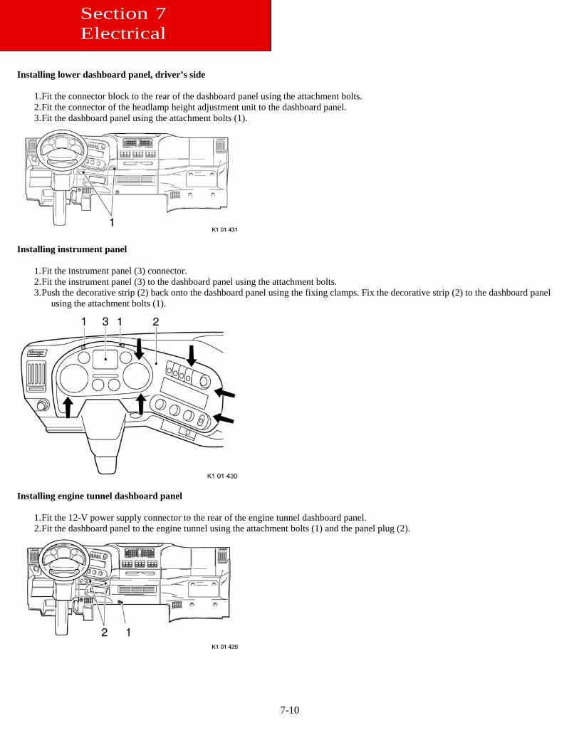
7-10
Installing lower dashboard panel, driver’s side
1. Fit the connector block to the rear of the dashboard panel using the attachment bolts. 2. Fit the connector of the headlamp height adjustment unit to the dashboard panel. 3. Fit the dashboard panel using the attachment bolts (1).
Installing instrument panel
1. Fit the instrument panel (3) connector. 2. Fit the instrument panel (3) to the dashboard panel using the attachment bolts. 3. Push the decorative strip (2) back onto the dashboard panel using the fixing clamps. Fix the decorative strip (2) to the dashboard panel
using the attachment bolts (1).
Installing engine tunnel dashboard panel
1. Fit the 12-V power supply connector to the rear of the engine tunnel dashboard panel. 2. Fit the dashboard panel to the engine tunnel using the attachment bolts (1) and the panel plug (2).
Section 7 Electrical
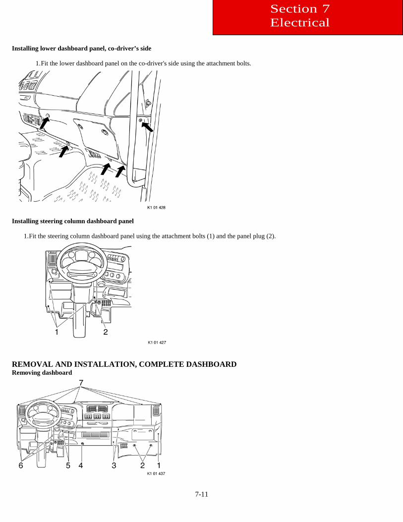
7-11
Installing lower dashboard panel, co-driver’s side
1. Fit the lower dashboard panel on the co-driver's side using the attachment bolts.
Installing steering column dashboard panel
1. Fit the steering column dashboard panel using the attachment bolts (1) and the panel plug (2).
REMOVAL AND INSTALLATION, COMPLETE DASHBOARD Removing dashboard
Section 7 Electrical
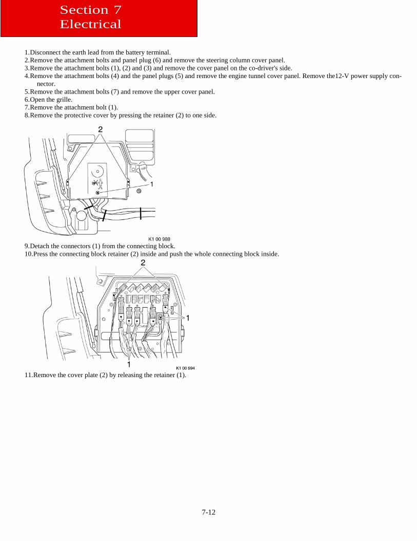
7-12
1. Disconnect the earth lead from the battery terminal. 2. Remove the attachment bolts and panel plug (6) and remove the steering column cover panel. 3. Remove the attachment bolts (1), (2) and (3) and remove the cover panel on the co-driver's side. 4. Remove the attachment bolts (4) and the panel plugs (5) and remove the engine tunnel cover panel. Remove the12-V power supply con-
nector. 5. Remove the attachment bolts (7) and remove the upper cover panel. 6. Open the grille. 7. Remove the attachment bolt (1). 8. Remove the protective cover by pressing the retainer (2) to one side.
9. Detach the connectors (1) from the connecting block. 10. Press the connecting block retainer (2) inside and push the whole connecting block inside.
11. Remove the cover plate (2) by releasing the retainer (1).
Section 7 Electrical
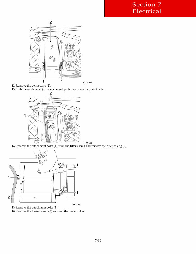
7-13
12. Remove the connectors (2). 13. Push the retainers (1) to one side and push the connector plate inside.
14. Remove the attachment bolts (1) from the filter casing and remove the filter casing (2).
15. Remove the attachment bolts (1). 16. Remove the heater hoses (2) and seal the heater tubes.
Section 7 Electrical
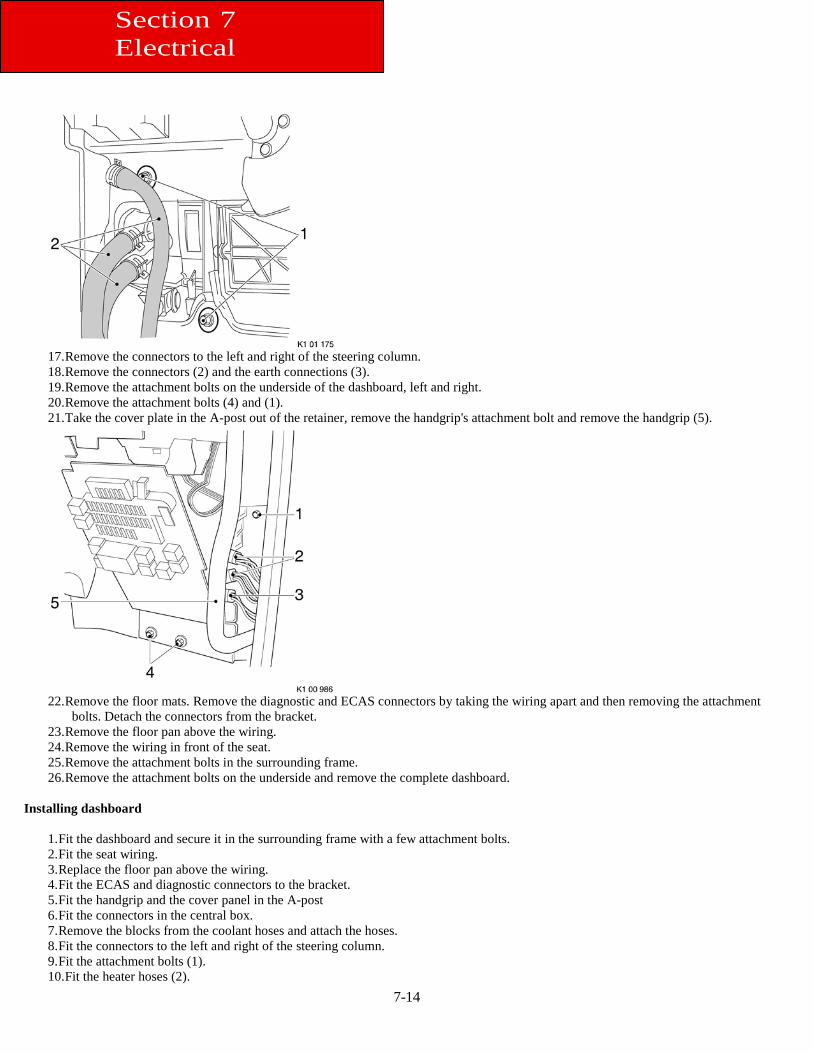
7-14
17. Remove the connectors to the left and right of the steering column. 18. Remove the connectors (2) and the earth connections (3). 19. Remove the attachment bolts on the underside of the dashboard, left and right. 20. Remove the attachment bolts (4) and (1). 21. Take the cover plate in the A-post out of the retainer, remove the handgrip's attachment bolt and remove the handgrip (5).
22. Remove the floor mats. Remove the diagnostic and ECAS connectors by taking the wiring apart and then removing the attachment
bolts. Detach the connectors from the bracket. 23. Remove the floor pan above the wiring. 24. Remove the wiring in front of the seat. 25. Remove the attachment bolts in the surrounding frame. 26. Remove the attachment bolts on the underside and remove the complete dashboard.
Installing dashboard
1. Fit the dashboard and secure it in the surrounding frame with a few attachment bolts. 2. Fit the seat wiring. 3. Replace the floor pan above the wiring. 4. Fit the ECAS and diagnostic connectors to the bracket. 5. Fit the handgrip and the cover panel in the A-post 6. Fit the connectors in the central box. 7. Remove the blocks from the coolant hoses and attach the hoses. 8. Fit the connectors to the left and right of the steering column. 9. Fit the attachment bolts (1). 10. Fit the heater hoses (2).
Section 7 Electrical
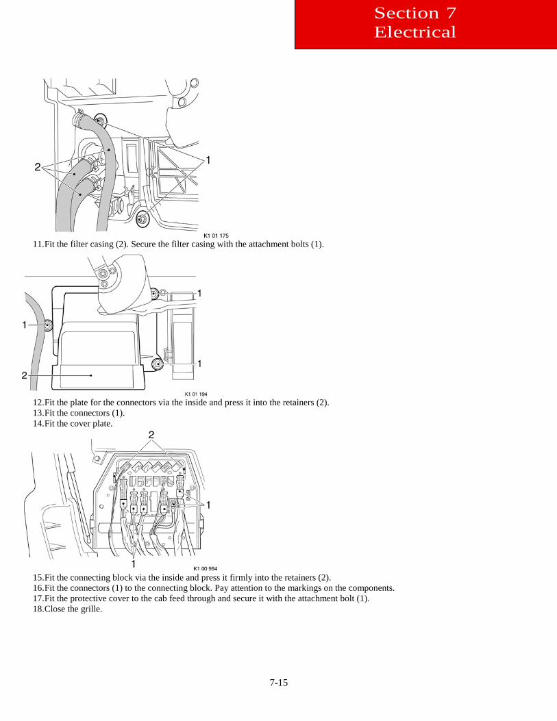
7-15
11. Fit the filter casing (2). Secure the filter casing with the attachment bolts (1).
12. Fit the plate for the connectors via the inside and press it into the retainers (2). 13. Fit the connectors (1). 14. Fit the cover plate.
15. Fit the connecting block via the inside and press it firmly into the retainers (2). 16. Fit the connectors (1) to the connecting block. Pay attention to the markings on the components. 17. Fit the protective cover to the cab feed through and secure it with the attachment bolt (1). 18. Close the grille.
Section 7 Electrical
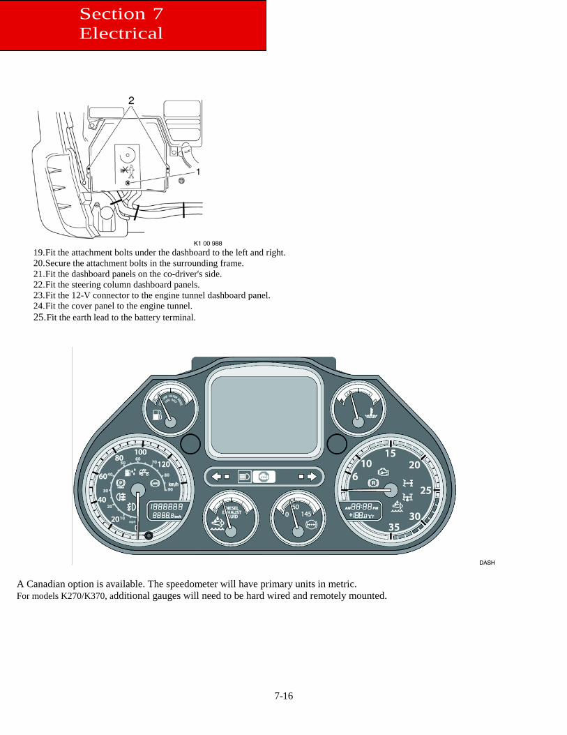
7-16
19. Fit the attachment bolts under the dashboard to the left and right. 20. Secure the attachment bolts in the surrounding frame. 21. Fit the dashboard panels on the co-driver's side. 22. Fit the steering column dashboard panels. 23. Fit the 12-V connector to the engine tunnel dashboard panel. 24. Fit the cover panel to the engine tunnel. 25. Fit the earth lead to the battery terminal.
A Canadian option is available. The speedometer will have primary units in metric. For models K270/K370, additional gauges will need to be hard wired and remotely mounted.
Section 7 Electrical
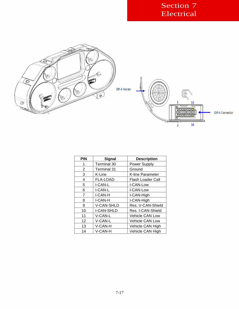
7-17
PIN Signal Description 1 Terminal 30 Power Supply 2 Terminal 31 Ground 3 K-Line K-line Parameter 4 FLA-LOAD Flash Loader Call 5 I-CAN-L I-CAN-Low 6 I-CAN-L I-CAN-Low 7 I-CAN-H I-CAN-High 8 I-CAN-H I-CAN-High 9 V-CAN-SHLD Res. V-CAN-Shield
10 I-CAN-SHLD Res. I-CAN-Shield 11 V-CAN-L Vehicle CAN Low 12 V-CAN-L Vehicle CAN Low 13 V-CAN-H Vehicle CAN High 14 V-CAN-H Vehicle CAN High
Section 7 Electrical
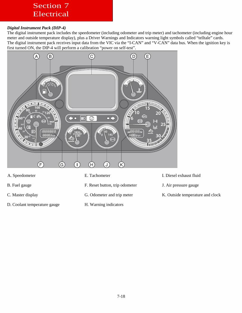
7-18
Digital Instrument Pack (DIP-4) The digital instrument pack includes the speedometer (including odometer and trip meter) and tachometer (including engine hour meter and outside temperature display), plus a Driver Warnings and Indicators warning light symbols called “telltale” cards. The digital instrument pack receives input data from the VIC via the “I-CAN” and “V-CAN” data bus. When the ignition key is first turned ON, the DIP-4 will perform a calibration “power on self-test”.
A. Speedometer E. Tachometer I. Diesel exhaust fluid
B. Fuel gauge F. Reset button, trip odometer J. Air pressure gauge
C. Master display G. Odometer and trip meter K. Outside temperature and clock
D. Coolant temperature gauge H. Warning indicators
Section 7 Electrical
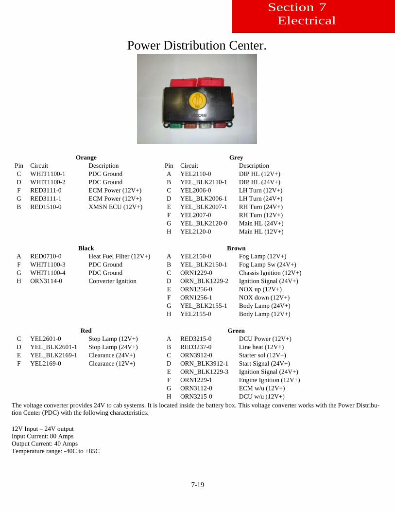
7-19
Power Distribution Center.
Orange Grey Pin Circuit Description Pin Circuit Description C WHIT1100-1 PDC Ground A YEL2110-0 DIP HL (12V+) D WHIT1100-2 PDC Ground B YEL_BLK2110-1 DIP HL (24V+) F RED3111-0 ECM Power (12V+) C YEL2006-0 LH Turn (12V+) G RED3111-1 ECM Power (12V+) D YEL_BLK2006-1 LH Turn (24V+) B RED1510-0 XMSN ECU (12V+) E YEL_BLK2007-1 RH Turn (24V+) F YEL2007-0 RH Turn (12V+) G YEL_BLK2120-0 Main HL (24V+) H YEL2120-0 Main HL (12V+)
Black Brown A RED0710-0 Heat Fuel Filter (12V+) A YEL2150-0 Fog Lamp (12V+) F WHIT1100-3 PDC Ground B YEL_BLK2150-1 Fog Lamp Sw (24V+) G WHIT1100-4 PDC Ground C ORN1229-0 Chassis Ignition (12V+) H ORN3114-0 Converter Ignition D ORN_BLK1229-2 Ignition Signal (24V+) E ORN1256-0 NOX up (12V+) F ORN1256-1 NOX down (12V+) G YEL_BLK2155-1 Body Lamp (24V+) H YEL2155-0 Body Lamp (12V+)
Red Green C YEL2601-0 Stop Lamp (12V+) A RED3215-0 DCU Power (12V+) D YEL_BLK2601-1 Stop Lamp (24V+) B RED3237-0 Line heat (12V+) E YEL_BLK2169-1 Clearance (24V+) C ORN3912-0 Starter sol (12V+) F YEL2169-0 Clearance (12V+) D ORN_BLK3912-1 Start Signal (24V+) E ORN_BLK1229-3 Ignition Signal (24V+) F ORN1229-1 Engine Ignition (12V+) G ORN3112-0 ECM w/u (12V+) H ORN3215-0 DCU w/u (12V+)
The voltage converter provides 24V to cab systems. It is located inside the battery box. This voltage converter works with the Power Distribu-tion Center (PDC) with the following characteristics: 12V Input – 24V output Input Current: 80 Amps Output Current: 40 Amps Temperature range: -40C to +85C
Section 7 Electrical
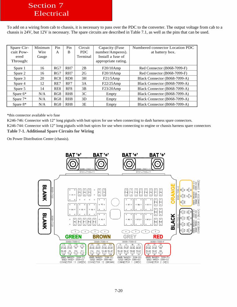
7-20
To add on a wiring from cab to chassis, it is necessary to pass over the PDC to the converter. The output voltage from cab to a chassis is 24V, but 12V is necessary. The spare circuits are described in Table 7.1, as well as the pins that can be used.
Spare Cir-cuit Pow-
ered Through:
Minimum Wire
Gauge
Pin A
Pin B
Circuit PDC
Terminal
Capacity (Fuse number/Amperes).
Install a fuse of appropriate rating.
Numbered connector Location PDC at battery box.
Spare 1 16 RG7 RH7 2B F20/10Amp Red Connector (B068-7099-F) Spare 2 16 RG7 RH7 2G F20/10Amp Red Connector (B068-7099-F) Spare 3 20 RC8 RD8 3H F21/5Amp Black Connector (B068-7099-A) Spare 4 12 RE7 RF7 3A F22/25Amp Black Connector (B068-7099-A) Spare 5 14 RE8 RF8 3B F23/20Amp Black Connector (B068-7099-A)
Spare 6* N/A RG8 RH8 3C Empty Black Connector (B068-7099-A) Spare 7* N/A RG8 RH8 3D Empty Black Connector (B068-7099-A) Spare 8* N/A RG8 RH8 3E Empty Black Connector (B068-7099-A)
*this connector available w/o fuse K246-746: Connector with 12” long pigtails with butt spices for use when connecting to dash harness spare connectors. K246-744: Connector with 12” long pigtails with butt spices for use when connecting to engine or chassis harness spare connectors Table 7-1. Additional Spare Circuits for Wiring
On Power Distribution Center (chassis).
Section 7 Electrical
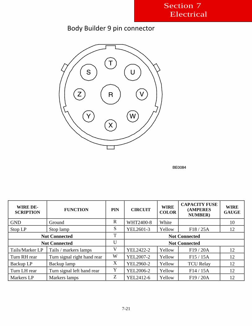
7-21
WIRE DE-SCRIPTION FUNCTION PIN CIRCUIT WIRE
COLOR
CAPACITY FUSE (AMPERES NUMBER)
WIRE GAUGE
GND Ground R WHT2400-8 White 10 Stop LP Stop lamp S YEL2601-3 Yellow F18 / 25A 12
Not Connected T Not Connected Not Connected U Not Connected
Tails/Marker LP Tails / markers lamps V YEL2422-2 Yellow F19 / 20A 12 Turn RH rear Turn signal right hand rear W YEL2007-2 Yellow F15 / 15A 12 Backup LP Backup lamp X YEL2960-2 Yellow TCU Relay 12 Turn LH rear Turn signal left hand rear Y YEL2006-2 Yellow F14 / 15A 12 Markers LP Markers lamps Z YEL2412-6 Yellow F19 / 20A 12
Body Builder 9 pin connector
Section 7 Electrical
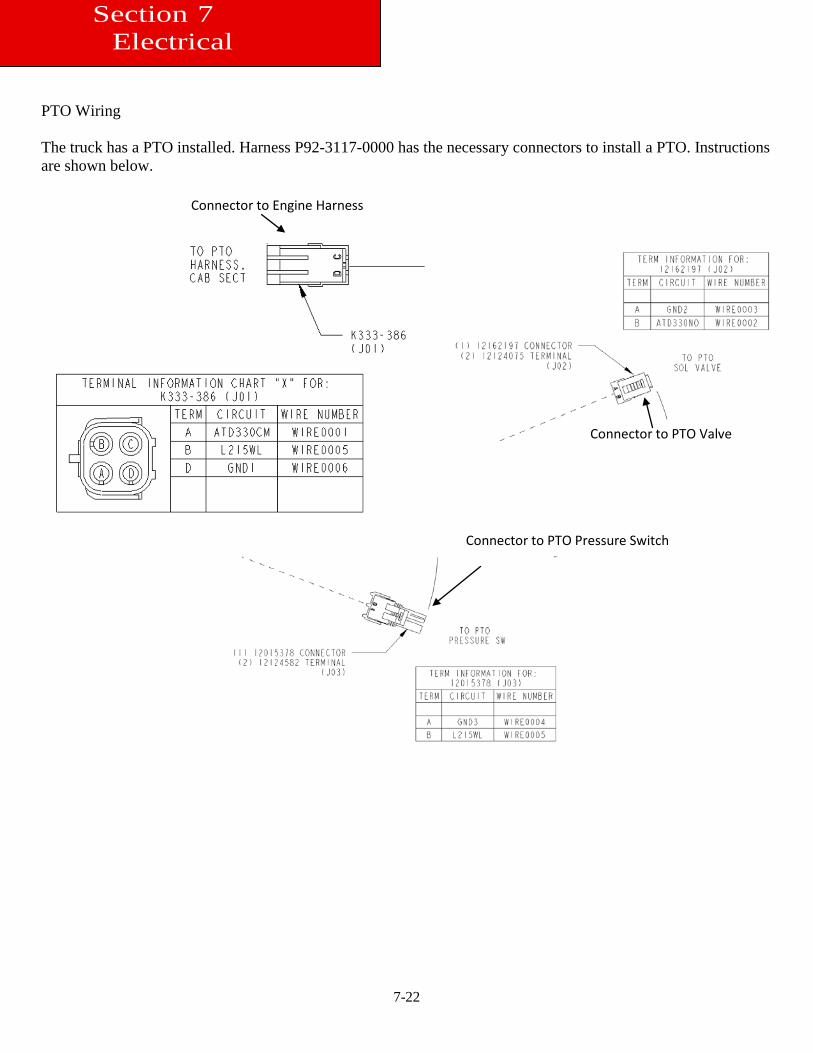
7-22
PTO Wiring The truck has a PTO installed. Harness P92-3117-0000 has the necessary connectors to install a PTO. Instructions are shown below.
Connector to Engine Harness
Connector to PTO Valve
Connector to PTO Pressure Switch
Section 7 Electrical
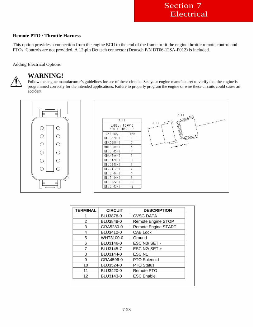
7-23
Remote PTO / Throttle Harness This option provides a connection from the engine ECU to the end of the frame to fit the engine throttle remote control and PTOs. Controls are not provided. A 12-pin Deutsch connector (Deutsch P/N DT06-12SA-P012) is included. Adding Electrical Options
WARNING! Follow the engine manufacturer’s guidelines for use of these circuits. See your engine manufacturer to verify that the engine is programmed correctly for the intended applications. Failure to properly program the engine or wire these circuits could cause an accident.
TERMINAL CIRCUIT DESCRIPTION 1 BLU3878-0 CVSG DATA 2 BLU3848-0 Remote Engine STOP 3 GRA5280-0 Remote Engine START 4 BLU3412-0 CAB Lock 5 WHT3100-0 Ground 6 BLU3146-0 ESC N3/ SET - 7 BLU3145-7 ESC N2/ SET + 8 BLU3144-0 ESC N1 9 GRA4596-0 PTO Solenoid 10 BLU3524-0 PTO Status 11 BLU3420-0 Remote PTO 12 BLU3143-0 ESC Enable
Section 7 Electrical
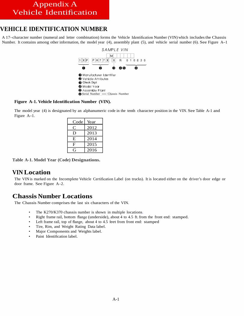
A-1
Appendix A Vehicle Identification
VEHICLE IDENTIFICATION NUMBER
A 17–character number (numeral and letter combination) forms the Vehicle Identification Number (VIN) which includes the Chassis Number. It contains among other information, the model year (4), assembly plant (5), and vehicle serial number (6). See Figure A–1
M
Serial Number Chassis Number
Figure A-1. Vehicle Identification Number (VIN).
The model year (4) is designated by an alphanumeric code in the tenth character position in the VIN. See Table A-1 and Figure A–1.
Code Year C 2012 D 2013 E 2014 F 2015 G 2016
Table A-1. Model Year (Code) Designations.
VIN Location The VIN is marked on the Incomplete Vehicle Certification Label (on trucks). It is located either on the driver’s door edge or door frame. See Figure A–2.
Chassis Number Locations The Chassis Number comprises the last six characters of the VIN.
• The K270/K370 chassis number is shown in multiple locations. • Right frame rail, bottom flange (underside), about 4 to 4.5 ft. from the front end: stamped. • Left frame rail, top of flange, about 4 to 4.5 feet from front end: stamped • Tire, Rim, and Weight Rating Data label. • Major Components and Weights label. • Paint Identification label.
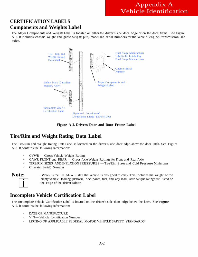
A-2
Appendix A Vehicle Identification
CERTIFICATION LABELS Components and Weights Label
The Major Components and Weights Label is located on either the driver’s side door edge or on the door frame. See Figure A–2. It includes: chassis weight and gross weight; plus, model and serial numbers for the vehicle, engine, transmission, and axles.
Tire, Rim and Weight Rating Data label
Safety Mark (Canadian Registry Only)
Final Stage Manufacturer Label to be Installed by Final Stage Manufacturer
Chassis Serial Number
Major Components and Weights Label
Incomplete Vehicle Certification Label
Figure A-2. Locations of Certification Labels - Driver’s Door
Figure A-2. Drivers Door and Door Frame Label
Tire/Rim and Weight Rating Data Label
The Tire/Rim and Weight Rating Data Label is located on the driver’s side door edge, above the door latch. See Figure A–2. It contains the following information:
• • • •
Note:
GVWR — Gross Vehicle Weight Rating GAWR FRONT and REAR — Gross Axle Weight Ratings for Front and Rear Axle TIRE/RIM SIZES AND INFLATION PRESSURES — Tire/Rim Sizes and Cold Pressure Minimums Chassis (Serial) Number
GVWR is the TOTAL WEIGHT the vehicle is designed to carry. This includes the weight of the empty vehicle, loading platform, occupants, fuel, and any load. Axle weight ratings are listed on the edge of the driver’s door.
Incomplete Vehicle Certification Label
The Incomplete Vehicle Certification Label is located on the driver’s side door edge below the latch. See Figure A–2. It contains the following information:
• DATE OF MANUFACTURE • VIN — Vehicle Identification Number • LISTING OF APPLICABLE FEDERAL MOTOR VEHICLE SAFETY STANDARDS
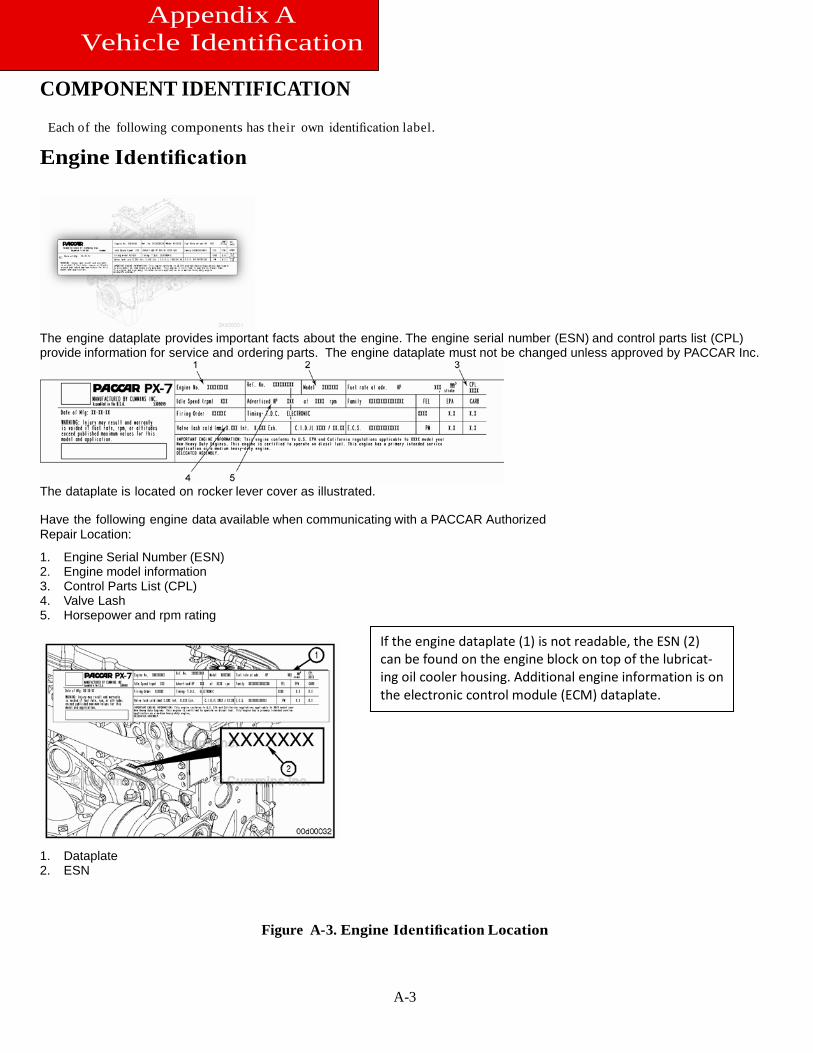
A-3
Appendix A Vehicle Identification
COMPONENT IDENTIFICATION
Each of the following components has their own identification label.
Engine Identification
The engine dataplate provides important facts about the engine. The engine serial number (ESN) and control parts list (CPL) provide information for service and ordering parts. The engine dataplate must not be changed unless approved by PACCAR Inc.
The dataplate is located on rocker lever cover as illustrated. Have the following engine data available when communicating with a PACCAR Authorized Repair Location:
1. Engine Serial Number (ESN) 2. Engine model information 3. Control Parts List (CPL) 4. Valve Lash 5. Horsepower and rpm rating
1. Dataplate 2. ESN
Figure A-3. Engine Identification Location
If the engine dataplate (1) is not readable, the ESN (2) can be found on the engine block on top of the lubricat-ing oil cooler housing. Additional engine information is on the electronic control module (ECM) dataplate.
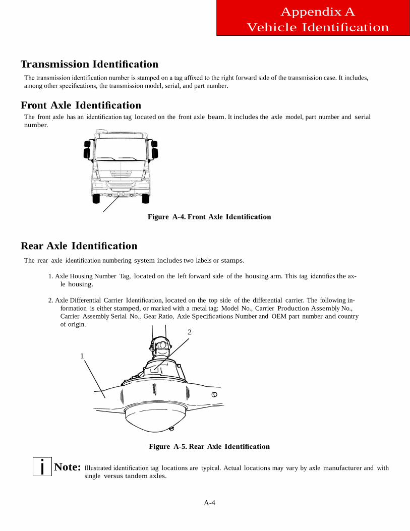
A-4
Appendix A Vehicle Identification
Transmission Identification
The transmission identification number is stamped on a tag affixed to the right forward side of the transmission case. It includes, among other specifications, the transmission model, serial, and part number.
Front Axle Identification
The front axle has an identification tag located on the front axle beam. It includes the axle model, part number and serial number.
Figure A-4. Front Axle Identification
Rear Axle Identification
The rear axle identification numbering system includes two labels or stamps.
1. Axle Housing Number Tag, located on the left forward side of the housing arm. This tag identifies the ax-le housing.
2. Axle Differential Carrier Identification, located on the top side of the differential carrier. The following in-
formation is either stamped, or marked with a metal tag: Model No., Carrier Production Assembly No., Carrier Assembly Serial No., Gear Ratio, Axle Specifications Number and OEM part number and country of origin.
2
1
Figure A-5. Rear Axle Identification
Note:
Illustrated identification tag locations are typical. Actual locations may vary by axle manufacturer and with single versus tandem axles.
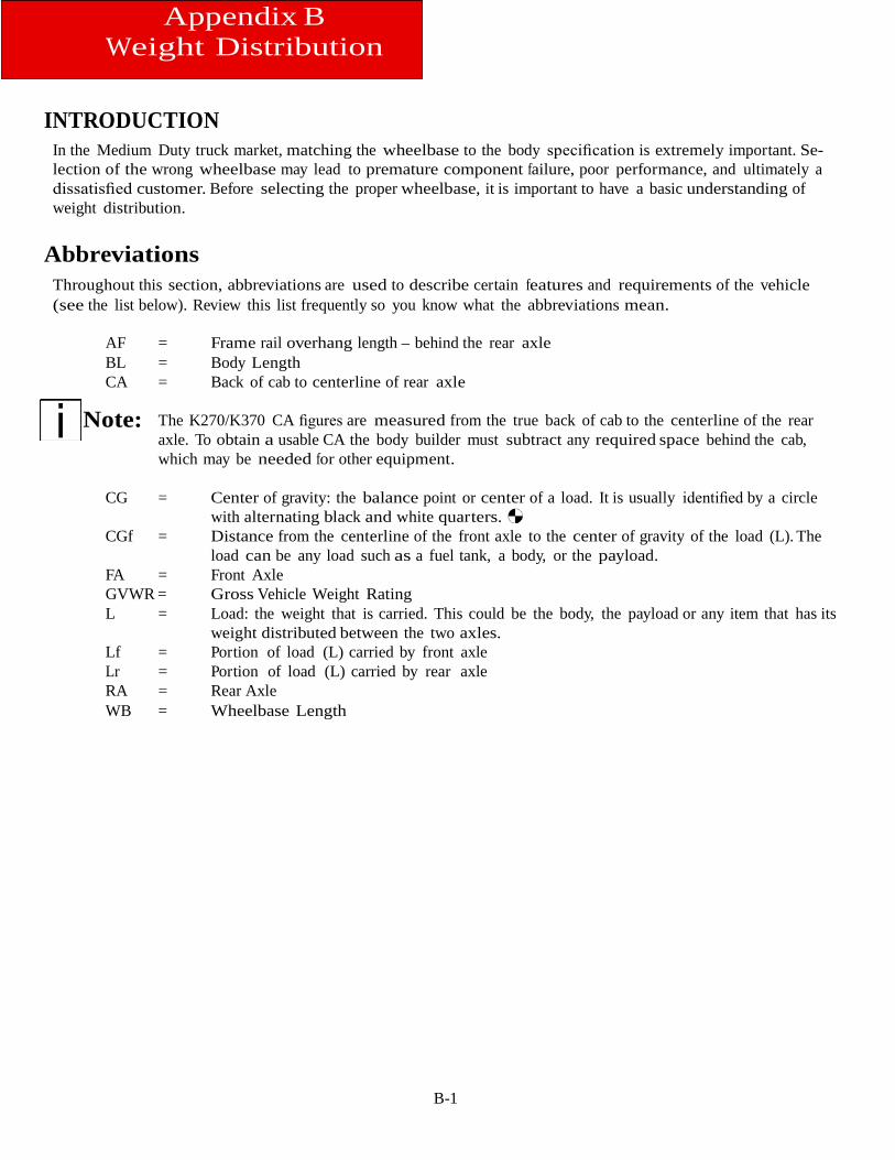
B-1
Appendix B Weight Distribution
INTRODUCTION
In the Medium Duty truck market, matching the wheelbase to the body specification is extremely important. Se-lection of the wrong wheelbase may lead to premature component failure, poor performance, and ultimately a dissatisfied customer. Before selecting the proper wheelbase, it is important to have a basic understanding of weight distribution.
Abbreviations
Throughout this section, abbreviations are used to describe certain features and requirements of the vehicle (see the list below). Review this list frequently so you know what the abbreviations mean.
AF = Frame rail overhang length – behind the rear axle BL = Body Length CA = Back of cab to centerline of rear axle
Note: The K270/K370 CA figures are measured from the true back of cab to the centerline of the rear axle. To obtain a usable CA the body builder must subtract any required space behind the cab, which may be needed for other equipment.
CG = Center of gravity: the balance point or center of a load. It is usually identified by a circle
with alternating black and white quarters. CGf = Distance from the centerline of the front axle to the center of gravity of the load (L). The
load can be any load such as a fuel tank, a body, or the payload. FA = Front Axle GVWR = Gross Vehicle Weight Rating L = Load: the weight that is carried. This could be the body, the payload or any item that has its
weight distributed between the two axles. Lf = Portion of load (L) carried by front axle Lr = Portion of load (L) carried by rear axle RA = Rear Axle WB = Wheelbase Length
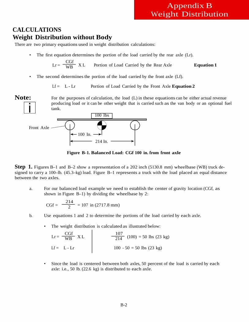
B-2
Appendix B Weight Distribution
CALCULATIONS Weight Distribution without Body There are two primary equations used in weight distribution calculations:
• The first equation determines the portion of the load carried by the rear axle (Lr).
CGf Lr = WB X L Portion of Load Carried by the Rear Axle Equation 1
• The second determines the portion of the load carried by the front axle (Lf).
Lf = L - Lr Portion of Load Carried by the Front Axle Equation 2
Note:
For the purposes of calculation, the load (L) in these equations can be either actual revenue producing load or it can be other weight that is carried such as the van body or an optional fuel tank.
100 lbs
Front Axle 100 In.
214 In.
Figure B-1. Balanced Load: CGf 100 in. from front axle Step 1. Figures B–1 and B–2 show a representation of a 202 inch (5130.8 mm) wheelbase (WB) truck de- signed to carry a 100–lb. (45.3–kg) load. Figure B–1 represents a truck with the load placed an equal distance between the two axles.
a. For our balanced load example we need to establish the center of gravity location (CGf, as
shown in Figure B–1) by dividing the wheelbase by 2:
214 CGf = 2 = 107 in (2717.8 mm)
b. Use equations 1 and 2 to determine the portions of the load carried by each axle.
• The weight distribution is calculated as illustrated below:
Lr =
CGf WB X L
107 214 (100) = 50 lbs (23 kg)
Lf = L - Lr 100 - 50 = 50 lbs (23 kg)
• Since the load is centered between both axles, 50 percent of the load is carried by each axle: i.e., 50 lb. (22.6 kg) is distributed to each axle.
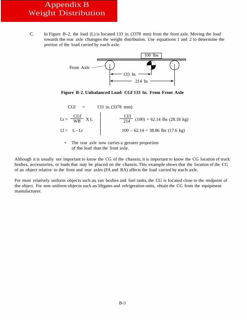
B-3
Appendix B Weight Distribution
C. In Figure B–2, the load (L) is located 133 in. (3378 mm) from the front axle. Moving the load towards the rear axle changes the weight distribution. Use equations 1 and 2 to determine the portion of the load carried by each axle.
100 lbs
Front Axle 133 In.
214 In.
Figure B-2. Unbalanced Load: CGf 133 In. From Front Axle
CGf = 133 in. (3378 mm)
Lr = CGf WB X L
133 214 (100) = 62.14 lbs (28.18 kg)
Lf = L - Lr 100 – 62.14 = 38.86 lbs (17.6 kg)
• The rear axle now carries a greater proportion of the load than the front axle.
Although it is usually not important to know the CG of the chassis; it is important to know the CG location of truck bodies, accessories, or loads that may be placed on the chassis. This example shows that the location of the CG of an object relative to the front and rear axles (FA and RA) affects the load carried by each axle.
For most relatively uniform objects such as van bodies and fuel tanks, the CG is located close to the midpoint of the object. For non–uniform objects such as liftgates and refrigeration units, obtain the CG from the equipment manufacturer.
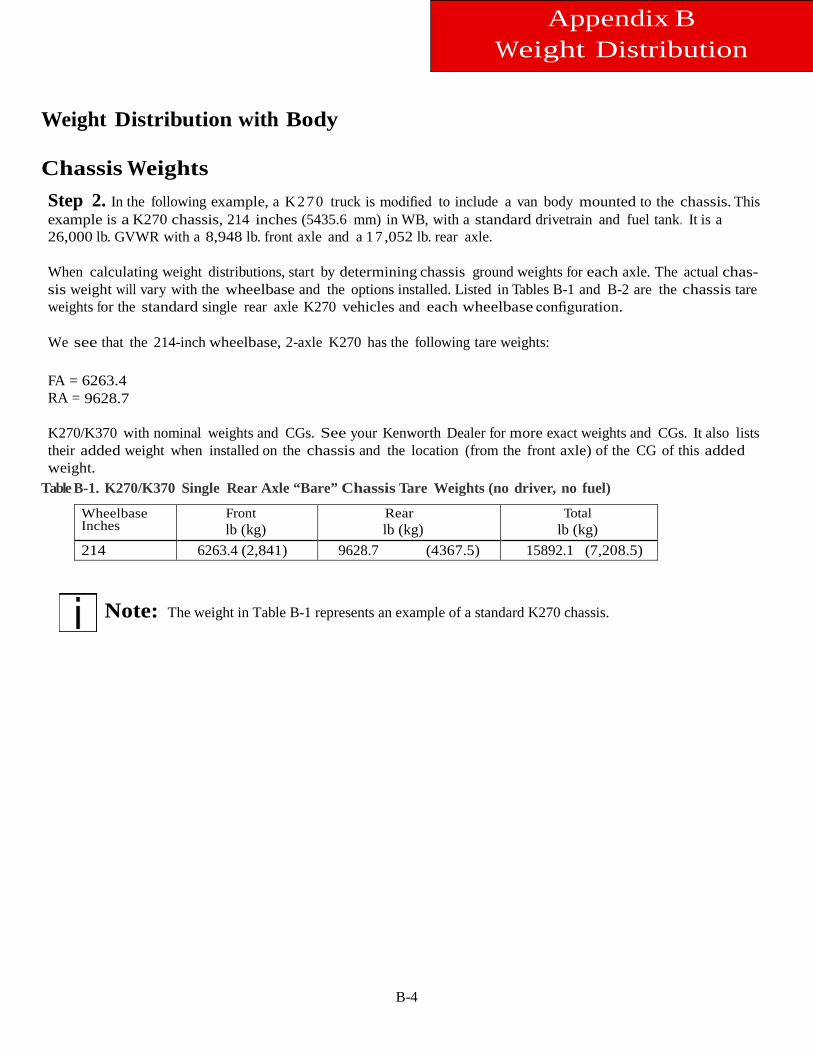
B-4
Appendix B Weight Distribution
Weight Distribution with Body Chassis Weights
Step 2. In the following example, a K 27 0 truck is modified to include a van body mounted to the chassis. This example is a K270 chassis, 214 inches (5435.6 mm) in WB, with a standard drivetrain and fuel tank. It is a 26,000 lb. GVWR with a 8,948 lb. front axle and a 1 7 ,052 lb. rear axle.
When calculating weight distributions, start by determining chassis ground weights for each axle. The actual chas-sis weight will vary with the wheelbase and the options installed. Listed in Tables B-1 and B-2 are the chassis tare weights for the standard single rear axle K270 vehicles and each wheelbase configuration.
We see that the 214-inch wheelbase, 2-axle K270 has the following tare weights:
FA = 6263.4 RA = 9628.7
K270/K370 with nominal weights and CGs. See your Kenworth Dealer for more exact weights and CGs. It also lists their added weight when installed on the chassis and the location (from the front axle) of the CG of this added weight.
Table B-1. K270/K370 Single Rear Axle “Bare” Chassis Tare Weights (no driver, no fuel) Wheelbase Inches
Front lb (kg)
Rear lb (kg)
Total lb (kg)
214 6263.4 (2,841) 9628.7 (4367.5) 15892.1 (7,208.5)
Note: The weight in Table B-1 represents an example of a standard K270 chassis.
Appendix
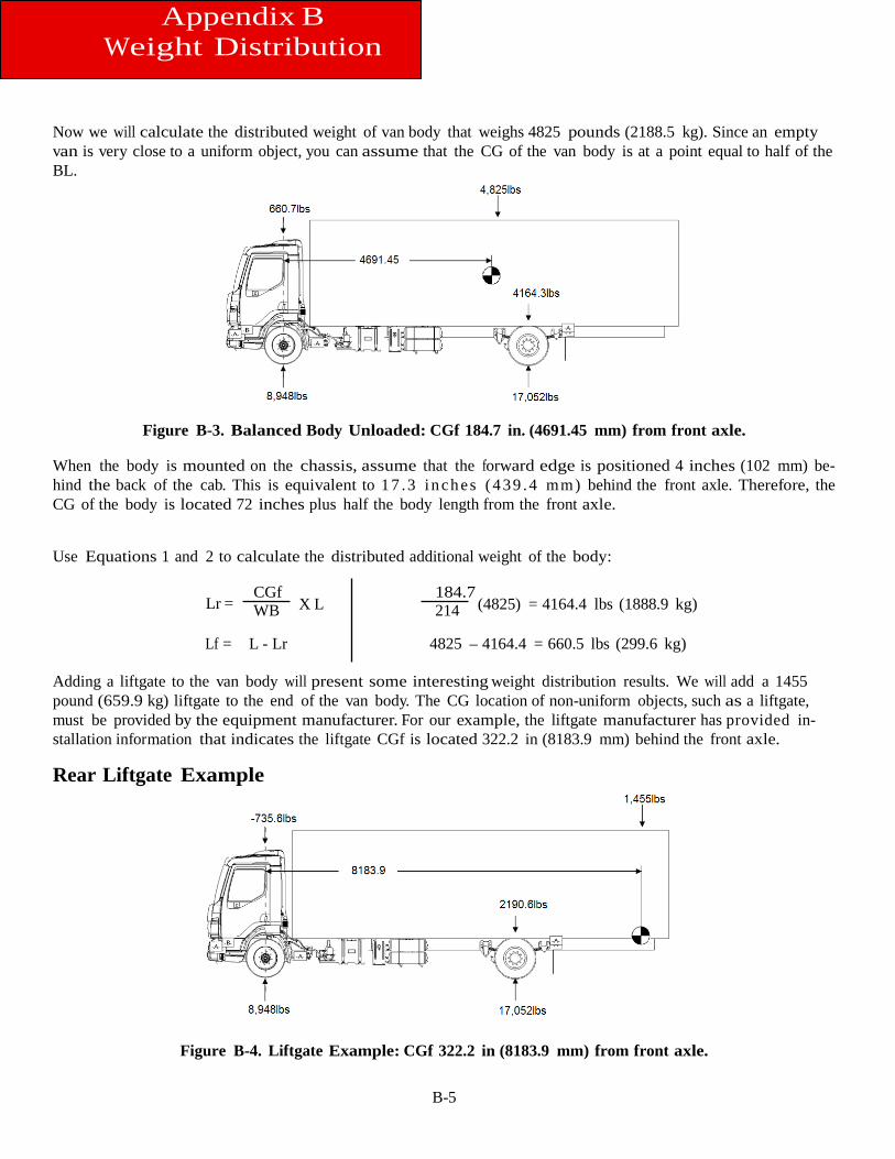
B-5
Appendix B Weight Distribution
Now we will calculate the distributed weight of van body that weighs 4825 pounds (2188.5 kg). Since an empty van is very close to a uniform object, you can assume that the CG of the van body is at a point equal to half of the BL.
Figure B-3. Balanced Body Unloaded: CGf 184.7 in. (4691.45 mm) from front axle.
When the body is mounted on the chassis, assume that the forward edge is positioned 4 inches (102 mm) be- hind the back of the cab. This is equivalent to 1 7 .3 i n ch es (4 39 .4 mm) behind the front axle. Therefore, the CG of the body is located 72 inches plus half the body length from the front axle.
Use Equations 1 and 2 to calculate the distributed additional weight of the body:
Lr = CGf WB X L
184.7 214 (4825) = 4164.4 lbs (1888.9 kg)
Lf = L - Lr 4825 – 4164.4 = 660.5 lbs (299.6 kg)
Adding a liftgate to the van body will present some interesting weight distribution results. We will add a 1455 pound (659.9 kg) liftgate to the end of the van body. The CG location of non-uniform objects, such as a liftgate, must be provided by the equipment manufacturer. For our example, the liftgate manufacturer has provided in-stallation information that indicates the liftgate CGf is located 322.2 in (8183.9 mm) behind the front axle.
Rear Liftgate Example
Figure B-4. Liftgate Example: CGf 322.2 in (8183.9 mm) from front axle.
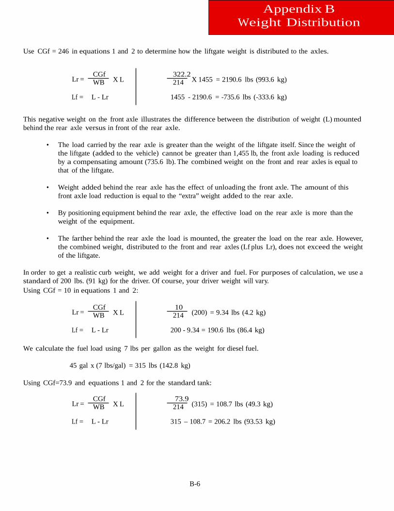
B-6
Appendix B Weight Distribution
Use CGf = 246 in equations 1 and 2 to determine how the liftgate weight is distributed to the axles.
Lr = CGf WB X L
322.2 214 X 1455 = 2190.6 lbs (993.6 kg)
Lf = L - Lr 1455 - 2190.6 = -735.6 lbs (-333.6 kg) This negative weight on the front axle illustrates the difference between the distribution of weight (L) mounted behind the rear axle versus in front of the rear axle.
• The load carried by the rear axle is greater than the weight of the liftgate itself. Since the weight of
the liftgate (added to the vehicle) cannot be greater than 1,455 lb, the front axle loading is reduced by a compensating amount (735.6 lb). The combined weight on the front and rear axles is equal to that of the liftgate.
• Weight added behind the rear axle has the effect of unloading the front axle. The amount of this
front axle load reduction is equal to the “extra” weight added to the rear axle.
• By positioning equipment behind the rear axle, the effective load on the rear axle is more than the weight of the equipment.
• The farther behind the rear axle the load is mounted, the greater the load on the rear axle. However,
the combined weight, distributed to the front and rear axles (Lf plus Lr), does not exceed the weight of the liftgate.
In order to get a realistic curb weight, we add weight for a driver and fuel. For purposes of calculation, we use a standard of 200 lbs. (91 kg) for the driver. Of course, your driver weight will vary. Using CGf = 10 in equations 1 and 2:
Lr = CGf WB X L
10 214 (200) = 9.34 lbs (4.2 kg)
Lf = L - Lr 200 - 9.34 = 190.6 lbs (86.4 kg) We calculate the fuel load using 7 lbs per gallon as the weight for diesel fuel.
45 gal x (7 lbs/gal) = 315 lbs (142.8 kg)
Using CGf=73.9 and equations 1 and 2 for the standard tank:
Lr = CGf WB X L
73.9 214 (315) = 108.7 lbs (49.3 kg)
Lf = L - Lr 315 – 108.7 = 206.2 lbs (93.53 kg)
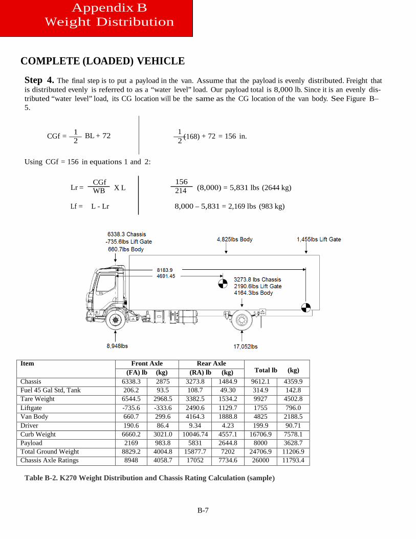
B-7
Appendix B Weight Distribution
COMPLETE (LOADED) VEHICLE Step 4. The final step is to put a payload in the van. Assume that the payload is evenly distributed. Freight that is distributed evenly is referred to as a “water level” load. Our payload total is 8,000 lb. Since it is an evenly dis-tributed “water level” load, its CG location will be the same as the CG location of the van body. See Figure B–5.
CGf = 1 2
BL + 72 1 (168) + 72 = 156 in. 2
Using CGf = 156 in equations 1 and 2:
Lr = CGf WB X L
156 214 (8,000) = 5,831 lbs (2644 kg)
Lf = L - Lr 8,000 – 5,831 = 2,169 lbs (983 kg) Item Front Axle Rear Axle
Total lb (kg) (FA) lb (kg) (RA) lb (kg) Chassis 6338.3 2875 3273.8 1484.9 9612.1 4359.9 Fuel 45 Gal Std, Tank 206.2 93.5 108.7 49.30 314.9 142.8 Tare Weight 6544.5 2968.5 3382.5 1534.2 9927 4502.8 Liftgate -735.6 -333.6 2490.6 1129.7 1755 796.0 Van Body 660.7 299.6 4164.3 1888.8 4825 2188.5 Driver 190.6 86.4 9.34 4.23 199.9 90.71 Curb Weight 6660.2 3021.0 10046.74 4557.1 16706.9 7578.1 Payload 2169 983.8 5831 2644.8 8000 3628.7 Total Ground Weight 8829.2 4004.8 15877.7 7202 24706.9 11206.9 Chassis Axle Ratings 8948 4058.7 17052 7734.6 26000 11793.4
Table B-2. K270 Weight Distribution and Chassis Rating Calculation (sample)
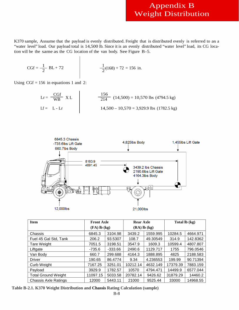
B-8
K370 sample, Assume that the payload is evenly distributed. Freight that is distributed evenly is referred to as a “water level” load. Our payload total is 14,500 lb. Since it is an evenly distributed “water level” load, its CG loca-tion will be the same as the CG location of the van body. See Figure B–5.
CGf = 1 2
BL + 72 1 (168) + 72 = 156 in. 2
Using CGf = 156 in equations 1 and 2:
Lr = CGf WB X L
156 214 (14,500) = 10,570 lbs (4794.5 kg)
Lf = L - Lr 14,500 – 10,570 = 3,929.9 lbs (1782.5 kg)
Table B-2.1. K370 Weight Distribution and Chassis Rating Calculation (sample)
Item Front Axle Rear Axle Total lb (kg) (FA) lb (kg) (RA) lb (kg)
Chassis 6845.3 3104.98 3439.2 1559.995 10284.5 4664.971 Fuel 45 Gal Std, Tank 206.2 93.5307 108.7 49.30549 314.9 142.8362 Tare Weight 7051.5 3198.51 3547.9 1609.3 10599.4 4807.807 Liftgate -735.6 -333.66 2490.6 1129.717 1755 796.0546 Van Body 660.7 299.688 4164.3 1888.895 4825 2188.583 Driver 190.65 86.4774 9.34 4.236553 199.99 90.71394 Curb Weight 7167.25 3251.01 10212.14 4632.149 17379.39 7883.159 Payload 3929.9 1782.57 10570 4794.471 14499.9 6577.044 Total Ground Weight 11097.15 5033.58 20782.14 9426.62 31879.29 14460.2 Chassis Axle Ratings 12000 5443.11 21000 9525.44 33000 14968.55
Appendix B Weight Distribution
B-9
Appendix B Weight Distribution
Weight Distribution Analysis Step 5. The final step is to total all of the front and rear axle weights to ensure that the axles are not overload-ed. Table B-4 shows the assembled information in an easy to read format.
• Compare the calculated axle ground totals against the axle weight ratings to be sure that the truck is
properly specified to haul this load.
• From this, it is evident that the chassis is properly equipped for this job. These calculations illustrate the importance of doing the weight distribution analysis. In some cases the addi-tion of one component (for example, a liftgate) can produce a dramatic difference.
Body Length
Step 6. Your analysis may produce results that indicate an overloaded axle with a total loaded chassis weight less than the GVW. This shows that you need to use a different body length for the truck. Each wheelbase can accommodate several different body lengths. However, for each wheelbase and GVW one particular body length will provide close to optimum weight distribution on both axles.
a. Tables B-5 and B-6 list Recommended Body Lengths for a particular wheelbase and
GVW. These body lengths provide the best weight distribution for the listed wheelbase.
Note: These charts were generated assuming a plain van body with “water level” loading. Any common additions such as lift gates or refrigeration units may indicate a different wheelbase for a given body length. Also, different body styles may require a different WB for a given size.
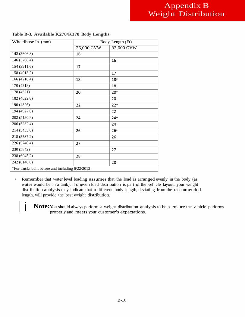
B-10
Appendix B Weight Distribution
Table B-3. Available K270/K370 Body Lengths
Wheelbase In. (mm) Body Length (Ft) 26,000 GVW 33,000 GVW
142 (3606.8) 16 146 (3708.4) 16 154 (3911.6) 17 158 (4013.2) 17 166 (4216.4) 18 18* 170 (4318) 18 178 (4521) 20 20* 182 (4622.8) 20 190 (4826) 22 22* 194 (4927.6) 22 202 (5130.8) 24 24* 206 (5232.4) 24 214 (5435.6) 26 26* 218 (5537.2) 26 226 (5740.4) 27 230 (5842) 27 238 (6045.2) 28 242 (6146.8) 28 *For trucks built before and including 6/22/2012
• Remember that water level loading assumes that the load is arranged evenly in the body (as water would be in a tank). If uneven load distribution is part of the vehicle layout, your weight distribution analysis may indicate that a different body length, deviating from the recommended length, will provide the best weight distribution.
Note:
You should always perform a weight distribution analysis to help ensure the vehicle performs properly and meets your customer’s expectations.
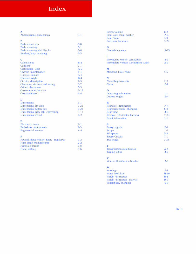
Index
A Abbreviations, dimensions 3-1
B Body mount, rear 5-8 Body mounting 5-1 Body mounting with U-bolts 5-6 Brackets, body mounting 5-5
C Calculations B-2 Cautions 2-1 Certification label A-2 Chassis maintenance 1-1 Chassis Number A-1 Chassis weight B-4 Circuits, description 7-3 Clearance, air lines and wiring 5-7 Critical clearances 5-3 Crossmember location 3-18 Crossmembers 6-4
D Dimensions 3-1 Dimensions, air tanks 3-21 Dimensions, battery box 3-21 Dimensions, crew cab, conversion 3-11 Dimensions, overall 3-2
E Electrical circuits 7-1 Emissions requirements 2-3 Engine serial number A-3
F Federal Motor Vehicle Safety Standards 2-2 Final stage manufacturer 2-2 Fishplate bracket 5-8 Frame, drilling 5-6
Frame, welding 6-2 Front axle serial number A-4 Front View 3-9 Fuel tank locations 3-22 G Ground clearance 3-23 I Incomplete vehicle certification 2-2 Incomplete Vehicle Certification Label A-2 M Mounting holes, frame 5-5 N Noise Requirements 2-3 Notes 2-1 O Operating information 1-1 Options weights B-4 R Rear axle identification A-4 Rear suspension, changing 6-3 Rear View 3-9 Remote PTO/throttle harness 7-23 Repair information 1-1 S Safety signals 2-1 Scope 1-1 Sill spacer 5-4 Spare Circuits 7-1 Step height 3-23 T Transmission identification A-4 Turning radius 3-2 V Vehicle Identification Number A-1 W Warnings 2-1 Water level load B-10 Weight distribution B-1 Weight distribution analysis B-9 Wheelbase, changing 6-3
06/13

®
A DIVISION OF PACCAR
Kenworth Truck Company P.O. Box 1000 Kirkland, WA 98083 (425) 828-5000e