Embed Size (px)
Citation preview
Elecraft • www.elecraft.com • 831-662-8345
Elecraft K3 AF Stage Upgrade Instructions (LINE OUT and Speaker Amplifier)
Revision B, November 20, 2008 Copyright © 2008, Elecraft, Inc. All Rights Reserved
Introduction
While the K3's speaker and line outputs meet the original K3 specifications, we've found that further improvement in performance is possible with minor changes. Both harmonic and intermodulation products can be reduced by 10 to 30 dB at both outputs. These changes are already being incorporated into new K3s.
The K3AFUPKT modification kit contains the parts to make both speaker amplifier and line audio output modifications, but you can choose to do either or both, as they are independent:
The line audio output modification is on page 8.
The speaker amplifier modification is below.
Tools Required
You will need a DMM for making resistance checks, No. 1 Phillips screwdriver, diagonal cutters, long nose pliers and a temperature controlled ESD-safe soldering iron with rosin core small diameter solder. A grounded wrist strap and ESD dissipating mat are recommended whenever you work inside your K3.
Observe ESD precautions when working inside your K3. Wear an ESD wrist strap or touch an unpainted, metal ground frequently while working.
Speaker Amplifier Modification
This mod changes RFC 47, 100 µH radio frequency choke that supplies power to the K3 audio amplifier. The original choke has a resistance of about 1.5 ohms. This resistance is high enough to cause some clipping of the audio signal at moderate volume settings, resulting in distortion products about 40 dB down. Replacing this choke with a physically larger unit with a resistance of about 0.2 ohms results in a 20 to 30 dB reduction in most distortion products.
RFC47 is located on the main K3 main RF board on the right side (viewed from the front) near the front panel shield. (See Figure 9). The replacement RFC is Elecraft part number E690017 shown in Figure 1 and Figure 10.
Choose Which Procedure You Want to Perform
Two procedures are provided for replacing the RFC. Do only one of them. Choose the procedure that best fits your skills:
1. First is a short procedure that simply disconnects the RFC by cutting a pc board trace and adds the new RFC across the open circuit. This is done entirely from the bottom of the K3. You need only remove the forward part of the bottom cover.
2. The second, longer procedure avoids cutting a pc board trace by removing the original RFC. You’ll need to remove and replace the KRX3 RF module (if installed) and the right side panel to gain access to the original RFC. A complete step-by-step procedure to do this is provided.
Some soldering is required but no work with SMDs is required by either procedure. In either procedure the new RFC is mounted on the bottom of the RF board.
Elecraft K3 Line Output and Speaker Output Upgrade Instructions Page 2 of 11
Short Procedure – Cutting the PC Board Trace
This is one of two alternate procedures you may use to change RFC 47. Do only one of them. See Choose Which Procedure You Want to Perform page 1 and decide which you want to do before proceeding:
Remove only the forward section of the bottom cover. The cover is held in place by seven screws (see Figure 8).
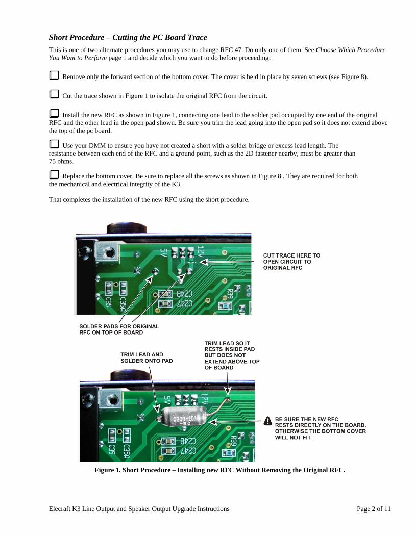
Cut the trace shown in Figure 1 to isolate the original RFC from the circuit.
Install the new RFC as shown in Figure 1, connecting one lead to the solder pad occupied by one end of the original RFC and the other lead in the open pad shown. Be sure you trim the lead going into the open pad so it does not extend above the top of the pc board.
Use your DMM to ensure you have not created a short with a solder bridge or excess lead length. The resistance between each end of the RFC and a ground point, such as the 2D fastener nearby, must be greater than 75 ohms.
Replace the bottom cover. Be sure to replace all the screws as shown in Figure 8 . They are required for both the mechanical and electrical integrity of the K3. That completes the installation of the new RFC using the short procedure.
Figure 1. Short Procedure – Installing new RFC Without Removing the Original RFC.
Elecraft K3 Line Output and Speaker Output Upgrade Instructions Page 3 of 11
Longer Procedure – Removing the Original RFC
This is one of two alternate procedures you may use to change RFC 47. Do only one of them. See Choose Which Procedure You Want to Perform page 1 and decide which you want to do before proceeding:
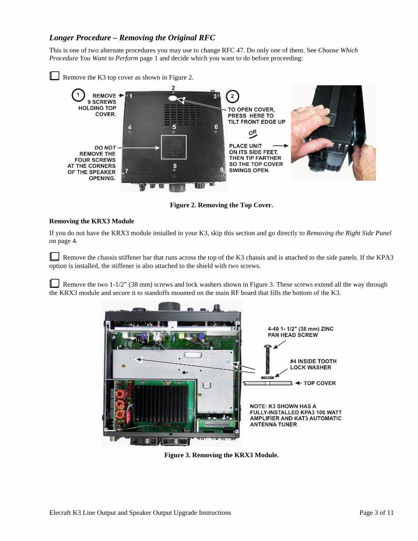
Remove the K3 top cover as shown in Figure 2.
Figure 2. Removing the Top Cover.
Removing the KRX3 Module
If you do not have the KRX3 module installed in your K3, skip this section and go directly to Removing the Right Side Panel on page 4.
Remove the chassis stiffener bar that runs across the top of the K3 chassis and is attached to the side panels. If the KPA3 option is installed, the stiffener is also attached to the shield with two screws.
Remove the two 1-1/2” (38 mm) screws and lock washers shown in Figure 3. These screws extend all the way through the KRX3 module and secure it to standoffs mounted on the main RF board that fills the bottom of the K3.
Figure 3. Removing the KRX3 Module.
Elecraft K3 Line Output and Speaker Output Upgrade Instructions Page 4 of 11
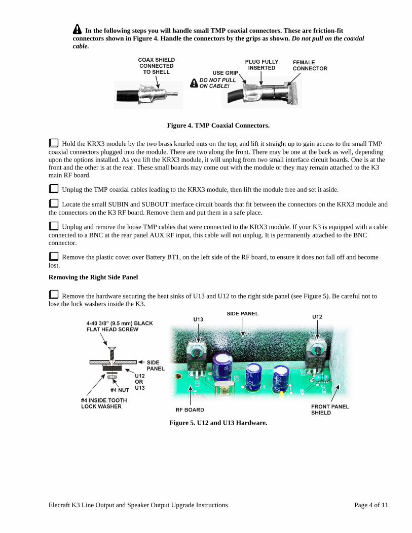
In the following steps you will handle small TMP coaxial connectors. These are friction-fit connectors shown in Figure 4. Handle the connectors by the grips as shown. Do not pull on the coaxial cable.
Figure 4. TMP Coaxial Connectors.
Hold the KRX3 module by the two brass knurled nuts on the top, and lift it straight up to gain access to the small TMP coaxial connectors plugged into the module. There are two along the front. There may be one at the back as well, depending upon the options installed. As you lift the KRX3 module, it will unplug from two small interface circuit boards. One is at the front and the other is at the rear. These small boards may come out with the module or they may remain attached to the K3 main RF board.
Unplug the TMP coaxial cables leading to the KRX3 module, then lift the module free and set it aside.
Locate the small SUBIN and SUBOUT interface circuit boards that fit between the connectors on the KRX3 module and the connectors on the K3 RF board. Remove them and put them in a safe place.
Unplug and remove the loose TMP cables that were connected to the KRX3 module. If your K3 is equipped with a cable connected to a BNC at the rear panel AUX RF input, this cable will not unplug. It is permanently attached to the BNC connector.
Remove the plastic cover over Battery BT1, on the left side of the RF board, to ensure it does not fall off and become lost.
Removing the Right Side Panel
Remove the hardware securing the heat sinks of U13 and U12 to the right side panel (see Figure 5). Be careful not to lose the lock washers inside the K3.
Figure 5. U12 and U13 Hardware.
Elecraft K3 Line Output and Speaker Output Upgrade Instructions Page 5 of 11
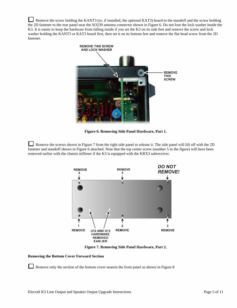
Remove the screw holding the KANT3 (or, if installed, the optional KAT3) board to the standoff and the screw holding the 2D fastener to the rear panel near the SO239 antenna connector shown in Figure 6. Do not lose the lock washer inside the K3. It is easier to keep the hardware from falling inside if you set the K3 on its side feet and remove the screw and lock washer holding the KANT3 or KAT3 board first, then set it on its bottom feet and remove the flat head screw from the 2D fastener.
Figure 6. Removing Side Panel Hardware, Part 1.
Remove the screws shown in Figure 7 from the right side panel to release it. The side panel will lift off with the 2D fastener and standoff shown in Figure 6 attached. Note that the top center screw (number 5 in the figure) will have been removed earlier with the chassis stiffener if the K3 is equipped with the KRX3 subreceiver.
Figure 7. Removing Side Panel Hardware, Part 2.
Removing the Bottom Cover Forward Section
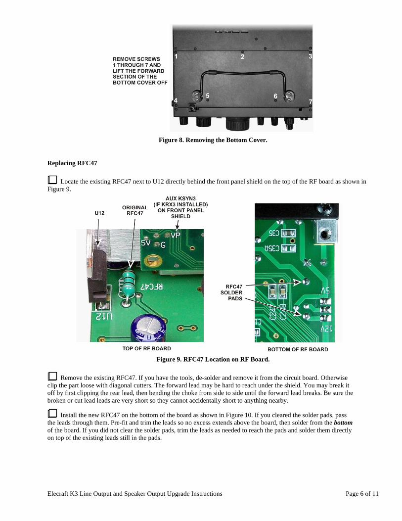
Remove only the section of the bottom cover nearest the front panel as shown in Figure 8
Elecraft K3 Line Output and Speaker Output Upgrade Instructions Page 6 of 11
Figure 8. Removing the Bottom Cover.
Replacing RFC47
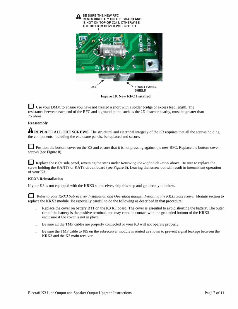
Locate the existing RFC47 next to U12 directly behind the front panel shield on the top of the RF board as shown in Figure 9.
Figure 9. RFC47 Location on RF Board.
Remove the existing RFC47. If you have the tools, de-solder and remove it from the circuit board. Otherwise clip the part loose with diagonal cutters. The forward lead may be hard to reach under the shield. You may break it off by first clipping the rear lead, then bending the choke from side to side until the forward lead breaks. Be sure the broken or cut lead leads are very short so they cannot accidentally short to anything nearby.
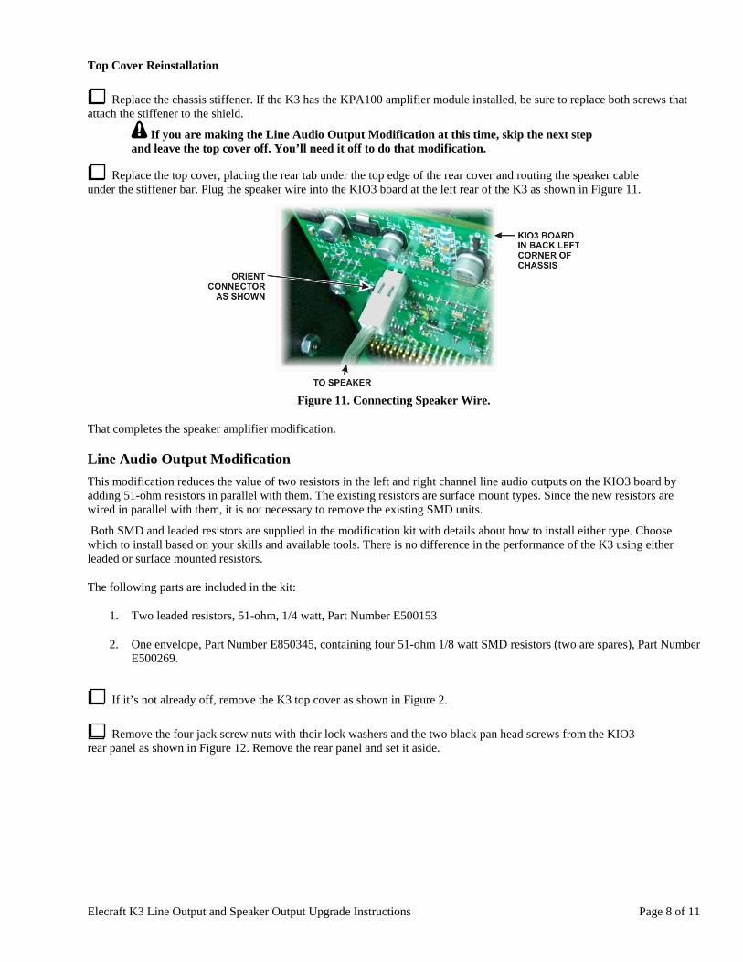
Install the new RFC47 on the bottom of the board as shown in Figure 10. If you cleared the solder pads, pass the leads through them. Pre-fit and trim the leads so no excess extends above the board, then solder from the bottom of the board. If you did not clear the solder pads, trim the leads as needed to reach the pads and solder them directly on top of the existing leads still in the pads.
Elecraft K3 Line Output and Speaker Output Upgrade Instructions Page 7 of 11
Figure 10. New RFC Installed.
Use your DMM to ensure you have not created a short with a solder bridge or excess lead length. The resistance between each end of the RFC and a ground point, such as the 2D fastener nearby, must be greater than 75 ohms.
Reassembly
REPLACE ALL THE SCREWS! The structural and electrical integrity of the K3 requires that all the screws holding the components, including the enclosure panels, be replaced and secure.
Position the bottom cover on the K3 and ensure that it is not pressing against the new RFC. Replace the bottom cover screws (see Figure 8).
Replace the right side panel, reversing the steps under Removing the Right Side Panel above. Be sure to replace the screw holding the KANT3 or KAT3 circuit board (see Figure 6). Leaving that screw out will result in intermittent operation of your K3.
KRX3 Reinstallation
If your K3 is not equipped with the KRX3 subreceiver, skip this step and go directly to below.
Refer to your KRX3 Subreceiver Installation and Operation manual, Installing the KRX3 Subreceiver Module section to replace the KRX3 module. Be especially careful to do the following as described in that procedure:
Replace the cover on battery BT1 on the K3 RF board. The cover is essential to avoid shorting the battery. The outer rim of the battery is the positive terminal, and may come in contact with the grounded bottom of the KRX3 enclosure if the cover is not in place.
Be sure all the TMP cables are properly connected or your K3 will not operate properly.
Be sure the TMP cable to J85 on the subreceiver module is routed as shown to prevent signal leakage between the KRX3 and the K3 main receiver.
Elecraft K3 Line Output and Speaker Output Upgrade Instructions Page 8 of 11
Top Cover Reinstallation
Replace the chassis stiffener. If the K3 has the KPA100 amplifier module installed, be sure to replace both screws that attach the stiffener to the shield.
If you are making the Line Audio Output Modification at this time, skip the next step and leave the top cover off. You’ll need it off to do that modification.
Replace the top cover, placing the rear tab under the top edge of the rear cover and routing the speaker cable under the stiffener bar. Plug the speaker wire into the KIO3 board at the left rear of the K3 as shown in Figure 11.
Figure 11. Connecting Speaker Wire.
That completes the speaker amplifier modification.
Line Audio Output Modification
This modification reduces the value of two resistors in the left and right channel line audio outputs on the KIO3 board by adding 51-ohm resistors in parallel with them. The existing resistors are surface mount types. Since the new resistors are wired in parallel with them, it is not necessary to remove the existing SMD units.
Both SMD and leaded resistors are supplied in the modification kit with details about how to install either type. Choose which to install based on your skills and available tools. There is no difference in the performance of the K3 using either leaded or surface mounted resistors.
The following parts are included in the kit:
1. Two leaded resistors, 51-ohm, 1/4 watt, Part Number E500153
2. One envelope, Part Number E850345, containing four 51-ohm 1/8 watt SMD resistors (two are spares), Part Number E500269.
If it’s not already off, remove the K3 top cover as shown in Figure 2.
Remove the four jack screw nuts with their lock washers and the two black pan head screws from the KIO3 rear panel as shown in Figure 12. Remove the rear panel and set it aside.
Elecraft K3 Line Output and Speaker Output Upgrade Instructions Page 9 of 11
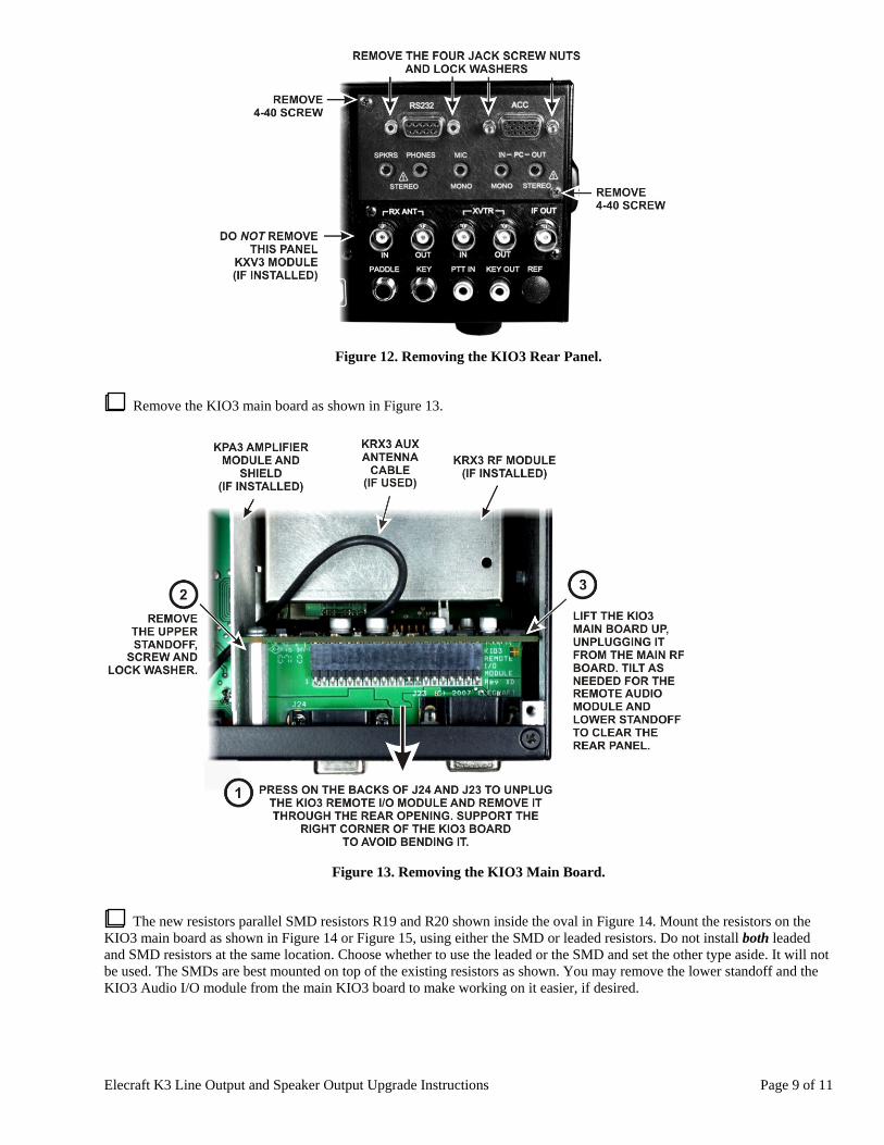
Figure 12. Removing the KIO3 Rear Panel.
Remove the KIO3 main board as shown in Figure 13.
Figure 13. Removing the KIO3 Main Board.
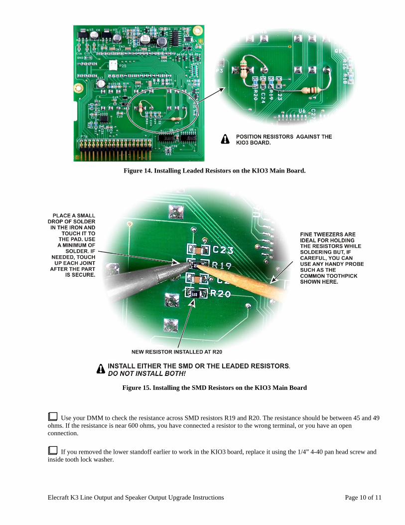
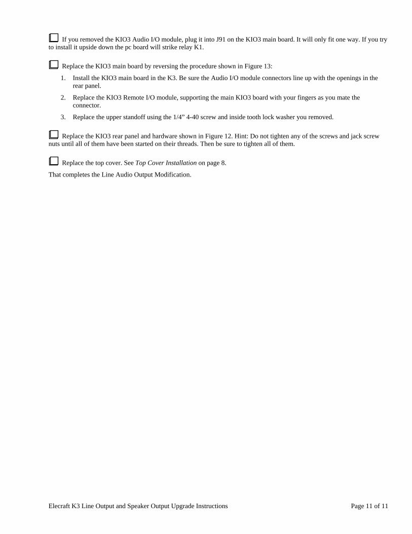
The new resistors parallel SMD resistors R19 and R20 shown inside the oval in Figure 14. Mount the resistors on the KIO3 main board as shown in Figure 14 or Figure 15, using either the SMD or leaded resistors. Do not install both leaded and SMD resistors at the same location. Choose whether to use the leaded or the SMD and set the other type aside. It will not be used. The SMDs are best mounted on top of the existing resistors as shown. You may remove the lower standoff and the KIO3 Audio I/O module from the main KIO3 board to make working on it easier, if desired.
Elecraft K3 Line Output and Speaker Output Upgrade Instructions Page 10 of 11
Figure 14. Installing Leaded Resistors on the KIO3 Main Board.
Figure 15. Installing the SMD Resistors on the KIO3 Main Board
Use your DMM to check the resistance across SMD resistors R19 and R20. The resistance should be between 45 and 49 ohms. If the resistance is near 600 ohms, you have connected a resistor to the wrong terminal, or you have an open connection.
If you removed the lower standoff earlier to work in the KIO3 board, replace it using the 1/4” 4-40 pan head screw and inside tooth lock washer.
Elecraft K3 Line Output and Speaker Output Upgrade Instructions Page 11 of 11
If you removed the KIO3 Audio I/O module, plug it into J91 on the KIO3 main board. It will only fit one way. If you try to install it upside down the pc board will strike relay K1.
Replace the KIO3 main board by reversing the procedure shown in Figure 13:
1. Install the KIO3 main board in the K3. Be sure the Audio I/O module connectors line up with the openings in the rear panel.
2. Replace the KIO3 Remote I/O module, supporting the main KIO3 board with your fingers as you mate the connector.
3. Replace the upper standoff using the 1/4” 4-40 screw and inside tooth lock washer you removed.
Replace the KIO3 rear panel and hardware shown in Figure 12. Hint: Do not tighten any of the screws and jack screw nuts until all of them have been started on their threads. Then be sure to tighten all of them.
Replace the top cover. See Top Cover Installation on page 8.
That completes the Line Audio Output Modification.