Embed Size (px)
Citation preview
Operating instructionsK3G310-RS01-I2Tr
ansl
atio
n of
the
orig
inal
ope
ratin
g in
stru
ctio
ns
ebm-papst Mulfingen GmbH & Co. KGBachmühle 2D-74673 MulfingenPhone +49 (0) 7938 81-0Fax +49 (0) 7938 [email protected]
CONTENTS
1. SAFETY REGULATIONS AND INFORMATION
11. SAFETY REGULATIONS AND INFORMATION
Read these operating instructions carefully before starting work on thedevice. Observe the following warnings to prevent malfunctions ordanger to persons.These operating instructions are to be regarded as part of the device.The device is only to be sold or passed on together with the operatinginstructions.These operating instructions may be duplicated and distributed to informabout potential dangers and their prevention.
1.1 Hazard levels for warnings11.1 Hazard levels for warnings
These operating instructions use the following hazard levels to indicatepotentially hazardous situations and important safety regulations:
DANGERIndicates an imminently hazardous situation which will result indeath or serious injury if the specified actions are not taken.Compliance with the instructions is imperative.
WARNINGIndicates a potentially hazardous situation which can result indeath or serious injury if the specified actions are not taken.Exercise extreme caution while working.
CAUTIONIndicates a potentially hazardous situation which can result inminor or moderate injury or damage to property if the specifiedactions are not taken.
NOTEA potentially harmful situation can occur and, if not avoided, canlead to property damage.
1.2 Staff qualifications
11.2 Staff qualifications
The device may only be transported, unpacked, installed, operated,maintained and otherwise used by suitably qualified, trained andauthorized technical staff.Only authorized specialists are permitted to install the device, to carryout a test run and to perform work on the electrical installation.
1.3 Basic safety rules
11.3 Basic safety rules
The safety hazards associated with the device must be assessed againfollowing installation in the final product.The locally applicable industrial safety regulations are always to beobserved when working on the device.Keep the workplace clean and tidy. Untidiness in the work areaincreases the risk of accidents.Note the following when working on the device:
; Do not perform any modifications, additions or conversions on thedevice without the approval of ebm-papst.
1.4 Voltage
11.4 Voltage
; Check the device's electrical equipment at regular intervals; seeChapter 6.3 Safety inspection.
; Replace loose connections and defective cables immediately.
DANGERElectrically charged deviceRisk of electric shock
→ When working on an electrically charged device, stand on arubber mat.
21.5 Safety and protective features21.6 Electromagnetic radiation21.7 Mechanical movement21.8 Emissions21.9 Hot surface21.10 Transport21.11 Storage
32. INTENDED USE
43. TECHNICAL DATA43.1 Product drawing53.2 Nominal data53.3 Data according to Commission Regulation (EU) 327/201153.4 Technical description63.5 Mounting data63.6 Transport and storage conditions63.7 Electromagnetic compatibility
64. CONNECTION AND STARTUP64.1 Mechanical connection74.2 Electrical connection84.3 Connecting the cables84.4 Factory settings94.5 Connection diagram104.6 Checking connections104.7 Switching on the device104.8 Switching off the device
105. INTEGRATED PROTECTIVE FEATURES
106. MAINTENANCE, MALFUNCTIONS, POSSIBLECAUSES AND REMEDIES
116.1 Vibration testing116.2 Cleaning126.3 Safety inspection126.4 Disposal
Item no. 52822-5-9970 · ENU · Change 204653 · Approved 2020-01-31 · Page 1 / 12
ebm-papst Mulfingen GmbH & Co. KG · Bachmühle 2 · D-74673 Mulfingen · Phone +49 (0) 7938 81-0 · Fax +49 (0) 7938 81-110 · [email protected] · www.ebmpapst.com
Operating instructionsK3G310-RS01-I2Tr
ansl
atio
n of
the
orig
inal
ope
ratin
g in
stru
ctio
ns
WARNINGLive terminals and connections even with deviceswitched offElectric shock
→ Wait five minutes after disconnecting the voltage at all polesbefore opening the device.
CAUTIONIn the event of a fault, the rotor and the impeller will beenergizedThe rotor and the impeller have basic insulation.
→ Do not touch the rotor and impeller once installed.
CAUTIONIf control voltage or a stored speed set value is applied,the motor will restart automatically, e.g. after a powerfailure.Risk of injury
→ Keep out of the device’s danger zone.
→ When working on the device, switch off the line voltageand ensure that it cannot be switched back on.
→ Wait until the device comes to a stop.
→ After working on the device, remove any tools or otherobjects from the device.
1.5 Safety and protective features
DANGERGuard missing and guard not functioningWithout a guard, hands may become caught up in the deviceduring operation for example, resulting in serious injury. Looseparts or items of clothing could be drawn in.
→ The device is a built-in component. As the owner, you areresponsible for ensuring that the device is adequatelysafeguarded.# Operate the device only with a fixedprotective device and guard grill.
→ Stop the device immediately if a protective device isfound to be missing or ineffective.
1.6 Electromagnetic radiation
Interference from electromagnetic radiation is possible, e.g. in conjunctionwith open- and closed-loop control devices.If impermissible radiation levels occur following installation, appropriateshielding measures have to be taken by the user.
NOTEElectrical or electromagnetic interference after installingthe device in customer equipment.
→ Verify that the entire setup is EMC-compliant.
1.7 Mechanical movement
DANGERRotating deviceRisk of injury to body parts coming into contact with the rotor orthe impeller.
→ Secure the device against accidental contact.
→ Before working on the system/machine, wait until allparts have come to a standstill.
WARNINGRotating deviceLong hair and dangling items of clothing, jewelry and the likecan become entangled and be pulled into the device. Injuriescan result.
→ Do not wear any loose-fitting or dangling clothing or jewelrywhile working on rotating parts.
→ Protect long hair with a cap.
1.8 Emissions
WARNINGDepending on the installation and operating conditions,the sound pressure level may exceed 70 dB(A).Risk of noise-induced hearing loss
→ Take appropriate technical safety measures.
→ Protect operating personnel with appropriate safetyequipment such as hearing protection.
→ Also observe the requirements of local agencies.
1.9 Hot surface
CAUTIONHigh temperature on electronics housingRisk of burns
→ Ensure sufficient protection against accidental contact.
1.10 Transport
NOTETransporting the device
→ Transport the device in its original packaging only.
→ Secure the device so it cannot slip, e.g. by using alashing strip.
WARNINGTransporting the fanInjuries from tipping or slipping
→ The fan is always to be transported with care and in itsoriginal packaging.
→ If set down too hard or at an angle for example, theimpact can lead to bearing damage or deformation of theframe or impeller.
→ It must be ensured that the fans cannot tip over duringtransportation and handling.
→ Secure the fan(s) with appropriate equipment such as alashing strip so that nothing can slip or tip, especially whenstacking multiple fans.
→ Also make allowance for possible wind forces.
1.11 Storage
; Store the device, partially or fully assembled, in a dry place,protected against the weather and free from vibration, in the originalpackaging in a clean environment.
; Protect the device against environmental effects and dirt until finalinstallation.
; We recommend storing the device for no longer than one year inorder to guarantee trouble-free operation and the longest possibleservice life.
Item no. 52822-5-9970 · ENU · Change 204653 · Approved 2020-01-31 · Page 2 / 12
ebm-papst Mulfingen GmbH & Co. KG · Bachmühle 2 · D-74673 Mulfingen · Phone +49 (0) 7938 81-0 · Fax +49 (0) 7938 81-110 · [email protected] · www.ebmpapst.com
Operating instructionsK3G310-RS01-I2Tr
ansl
atio
n of
the
orig
inal
ope
ratin
g in
stru
ctio
ns
; Even devices explicitly intended for outdoor use are to be stored asdescribed prior to commissioning.
; Maintain the storage temperature, seeChapter 3.6 Transport and storage conditions.
2. INTENDED USE
The device is exclusively designed as a built-in device for conveyingair according to its technical data.Any other usage above and beyond this does not conform with theintended purpose and constitutes misuse of the device.Customer equipment must be capable of withstanding the mechanicaland thermal stresses that can arise from this product. This applies for theentire service life of the equipment in which this product is installed.
Intended use also includes
● The device is only to be used in power systems with groundedneutral (TN/TT power systems), in power systems with phaseconductor grounding, or in IT power systems.
● Use of the device in stationary systems only.
● Performance of all maintenance work.
● Conveying air at an ambient air pressure between 800 mbar and1050 mbar.
● Using the device within the permitted ambient temperature range; seeChapter 3.6 Transport and storage conditions andChapter 3.2 Nominal data.
● Operating the device with all protective devices.
● Following the operating instructions.
Improper use
In particular, operating the device in the following ways is prohibited andcould be hazardous:
● Operating the device in an unbalanced state, e.g. due to dirt depositsor ice formation.
● Resonant operation, operation with severe vibration. This alsoincludes vibration transmitted to the fan from the customer installation.
● Operation in medical equipment with a life-sustaining or life-supportfunction.
● Conveying solids in the flow medium.
● Painting the device
● Connections (e.g. screws) coming loose during operation.
● Conveying air that contains abrasive particles.
● Conveying highly corrosive air, e.g. salt spray. Exception: devicesdesigned for salt spray and correspondingly protected.
● Conveying air with high dust content, e.g. suctioning off sawdust.
● Operating the device close to flammable materials or components.
● Operating the device in an explosive atmosphere.
● Using the device as a safety component or to perform safety-relatedfunctions.
● Operation with completely or partially disassembled or manipulatedprotective devices.
● In addition, all applications not listed among the intended uses.
Item no. 52822-5-9970 · ENU · Change 204653 · Approved 2020-01-31 · Page 3 / 12
ebm-papst Mulfingen GmbH & Co. KG · Bachmühle 2 · D-74673 Mulfingen · Phone +49 (0) 7938 81-0 · Fax +49 (0) 7938 81-110 · [email protected] · www.ebmpapst.com
Operating instructionsK3G310-RS01-I2Tr
ansl
atio
n of
the
orig
inal
ope
ratin
g in
stru
ctio
ns
3. TECHNICAL DATA
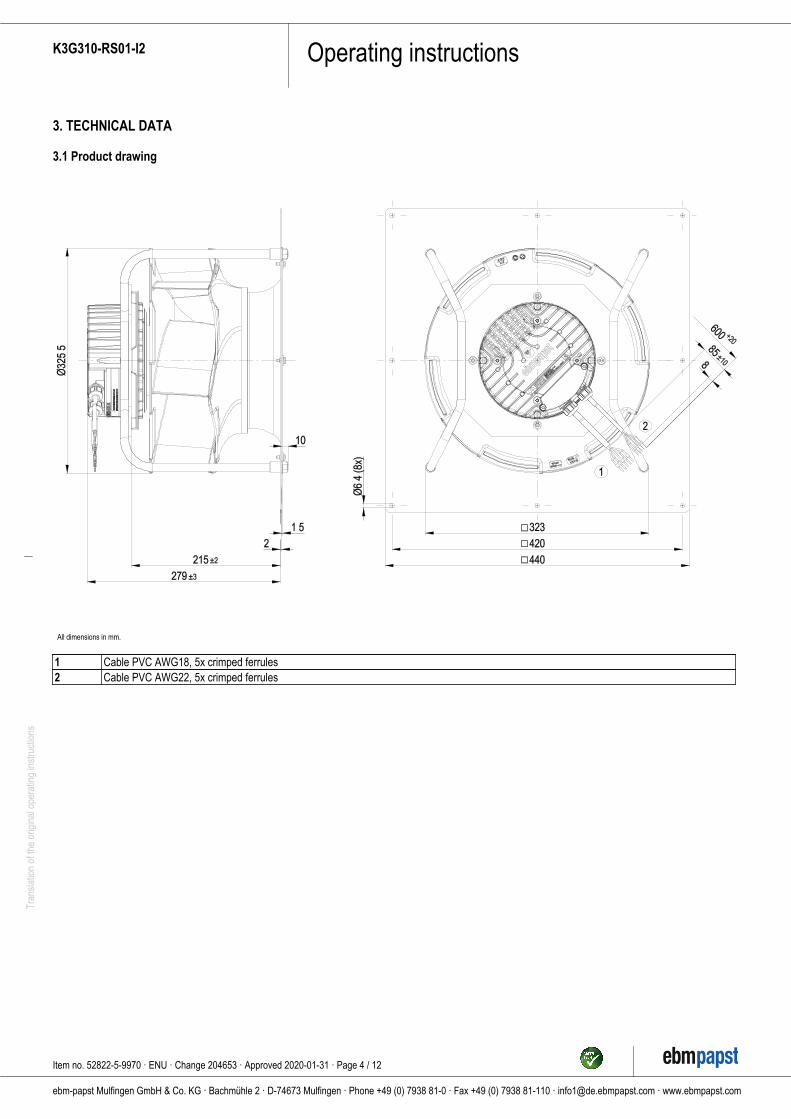
3.1 Product drawing
All dimensions in mm.
1 Cable PVC AWG18, 5x crimped ferrules2 Cable PVC AWG22, 5x crimped ferrules
Item no. 52822-5-9970 · ENU · Change 204653 · Approved 2020-01-31 · Page 4 / 12
ebm-papst Mulfingen GmbH & Co. KG · Bachmühle 2 · D-74673 Mulfingen · Phone +49 (0) 7938 81-0 · Fax +49 (0) 7938 81-110 · [email protected] · www.ebmpapst.com
Operating instructionsK3G310-RS01-I2Tr
ansl
atio
n of
the
orig
inal
ope
ratin
g in
stru
ctio
ns
3.2 Nominal data
Motor M3G084-FA
Phase 1~Nominal voltage / VAC 230Nominal voltagerange / VAC
200 .. 277
Frequency / Hz 50/60
Method of obtainingdata
ml
Speed (rpm) / min-1 2640Power consumption / W 730Current draw / A 3.20Min. ambienttemperature / °C
-25
Max. ambienttemperature / °C
60
ml = Max. load · me = Max. efficiency · fa = Free aircs = Customer specification · ce = Customer equipment
Subject to change
3.3 Data according to Commission Regulation (EU) 327/2011
Actual Req. 2015
01 Overall efficiency ηes / % 65.6 50.102 Measurement category A03 Efficiency category Static04 Efficiency grade N 77.5 6205 Variable speed drive Yes06 Year of manufacture The year of manufacture is specified on the
product's rating label.
07 Manufacturer ebm-papst Mulfingen GmbH & Co. KGAmtsgericht (court of registration) Stuttgart· HRA 590344D-74673 Mulfingen
08 Type K3G310-RS01-I209 Power consumption Ped / kW 0.7409 Air flow qv / m³/h 241009 Pressure increase total psf /Pa
661
10 Speed (rpm) n / min-1 264011 Specific ratio* 1.0112 Recycling/disposal Information on recycling and disposal is
provided in the operating instructions.
13 Maintenance Information on installation, operation andmaintenance is provided in the operatinginstructions.
14 Additional components Components used to calculate the energyefficiency that are not apparent from themeasurement category are detailed in theCE declaration.
* Specific ratio = 1 + pfs / 100 000 Pa
Data obtained at optimum efficiency level. The ErP data is determined using a motor-impellercombination in a standardized measurement setup.
3.4 Technical description
Weight 10.7 kgSize 310 mmMotor size 84Rotor surface Painted blackElectronics housingmaterial
Die-cast aluminum
Impeller material PP plasticSupport plate material Sheet steel, galvanizedSupport bracketmaterial
Steel, painted black
Inlet nozzle material Sheet steel, galvanizedNumber of blades 6Direction of rotation Clockwise, viewed toward rotorDegree of protection IP55Insulation class "F"Moisture (F) /Environmental (H)protection class
H1
Ambient temperaturenote
Occasional start-up between -40°C and -25°C is permissible.For continuous operation attemperatures below -25°C (e.g.refrigeration applications) we recommendour fan design with special low-temperature bearings.
Installation position Shaft horizontal or rotor on bottom; rotoron top on request
Condensationdrainage holes
On rotor side
Mode S1Motor bearing Ball bearingTechnical features - Output 10 VDC, max. 10 mA
- Operation and alarm display- Alarm relay- Integrated PID controller- Power limiter- Motor current limitation- PFC, active- RS-485 MODBUS-RTU- Soft start- Control input 0-10 VDC / PWM- Control interface with SELV potentialsafely disconnected from supply- Thermal overload protection forelectronics/motor- Line undervoltage / phase failuredetection
Touch currentaccording to IEC60990 (measuringcircuit Fig. 4, TNsystem)
<= 3.5 mA
Motor protection Thermal overload protector (TOP)internally connected
with cable VariableProtection class I (with customer connection of protective
earth)Conformity withstandards
EN 61800-5-1; EN 60335-1; CE
Item no. 52822-5-9970 · ENU · Change 204653 · Approved 2020-01-31 · Page 5 / 12
ebm-papst Mulfingen GmbH & Co. KG · Bachmühle 2 · D-74673 Mulfingen · Phone +49 (0) 7938 81-0 · Fax +49 (0) 7938 81-110 · [email protected] · www.ebmpapst.com
Operating instructionsK3G310-RS01-I2Tr
ansl
atio
n of
the
orig
inal
ope
ratin
g in
stru
ctio
ns
Approval EAC; CCC; CSA C22.2 No. 77 +CAN/CSA-E60730-1; UL 1004-7 +60730-1
With regard to cyclic speed loads, note that the rotating parts ofthe device are designed for a maximum of one million loadcycles. If you have special questions, consult ebm-papst forsupport.
; Use the device in accordance with its degree of protection.
Information on surface quality
The surfaces of the products conform to the generally applicable industrialstandard. The surface quality may change during the production period.This has no effect on strength, dimensional stability and dimensionalaccuracy.The color pigments in the paints used perceptibly react to UV light overthe course of time. This does not however in any way affect thetechnical properties of the products. The product is to be protected againstUV radiation to prevent the formation of patches and fading. Changes incolor are not a reason for complaint and are not covered by the warranty.
3.5 Mounting data
; Secure the screws against unintentional loosening (e.g. use self-locking screws).
For screw clearance, see Chapter 3.1 Product drawing
Strength class ofscrews
8.8
Any further mounting data required can be taken from the productdrawing or Section Chapter 4.1 Mechanical connection.
3.6 Transport and storage conditions
Max. permittedambient temp. formotor (transport/storage)
+80 °C
Min. permittedambient temp. formotor (transport/storage)
-40 °C
3.7 Electromagnetic compatibility
EMC immunity tointerference
According to EN 61000-6-2 (industrialenvironment)
EMC circuit feedback According to EN 61000-3-2/3EMC interferenceemission
According to EN 61000-6-3 (householdenvironment)
4. CONNECTION AND STARTUP
4.1 Mechanical connection
CAUTIONRisk of cutting and crushing when removing devicefrom packaging
→ Carefully remove the device from the packaging by graspinghold of the frame. Never subject to any impact.
→ Wear safety shoes and cut-resistant safety gloves.
CAUTIONHeavy load when unpacking deviceRisk of physical injury, such as back injuries.
→ Two people should work together to remove the device fromits packaging.
NOTEDamage to the device from vibrationBearing damage, shorter service life
→ The fan must not be subjected to force or excessive vibrationfrom sections of the installation.
→ If the fan is connected to air ducts, the connection shouldbe isolated from vibration, e.g. using compensators or similarelements.
→ Ensure stress-free attachment of the fan to thesubstructure.
; The fan may not be handled in the area around the inlet nozzle duringtransport and installation.There is a risk of damage to the impeller.
; Check the device for transport damage. Damaged devices are not tobe installed.
; Install the undamaged device in accordance with your application.
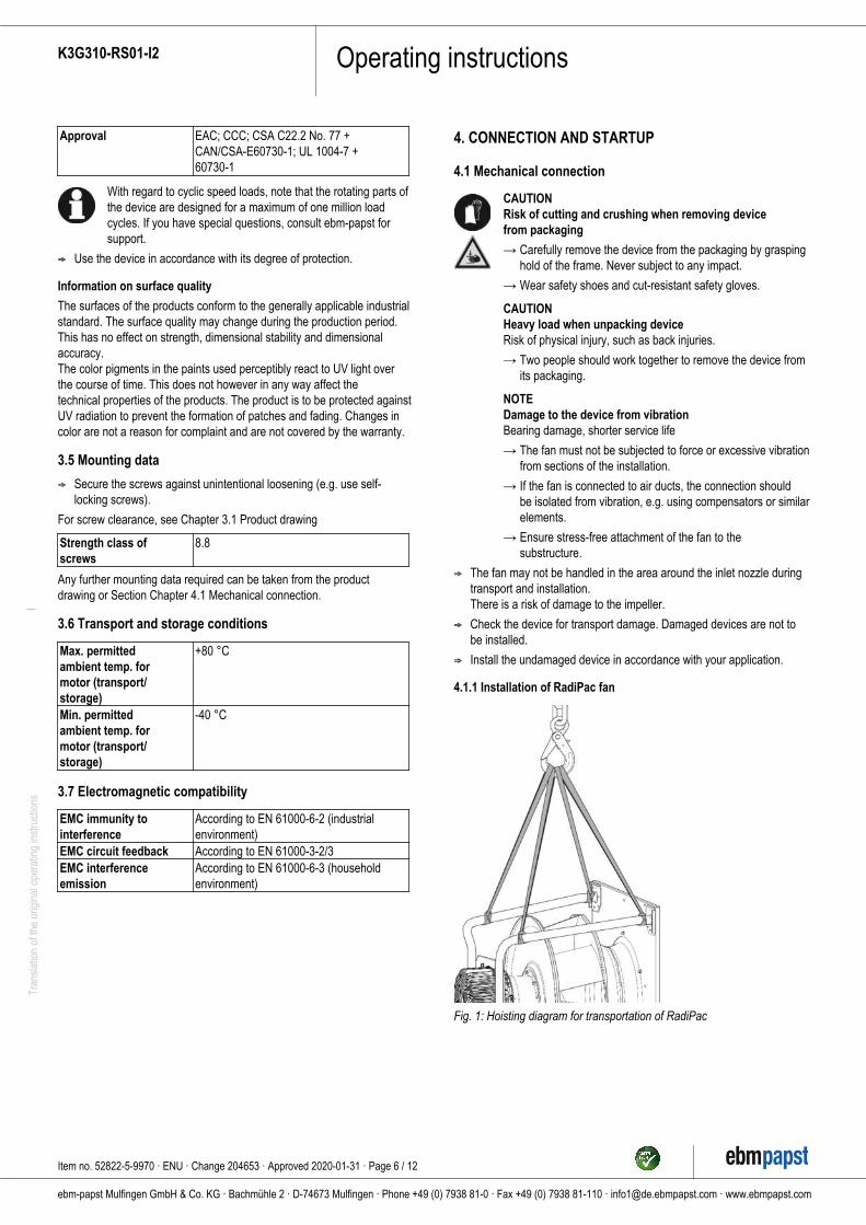
4.1.1 Installation of RadiPac fan
Fig. 1: Hoisting diagram for transportation of RadiPac
Item no. 52822-5-9970 · ENU · Change 204653 · Approved 2020-01-31 · Page 6 / 12
ebm-papst Mulfingen GmbH & Co. KG · Bachmühle 2 · D-74673 Mulfingen · Phone +49 (0) 7938 81-0 · Fax +49 (0) 7938 81-110 · [email protected] · www.ebmpapst.com
Operating instructionsK3G310-RS01-I2Tr
ansl
atio
n of
the
orig
inal
ope
ratin
g in
stru
ctio
ns
CAUTIONPossible damage to the deviceIf the device slips during installation, serious damage can result.
→ Ensure that the device is securely positioned at its place ofinstallation until all fastening screws have been tightened.
● The fan must not be strained on fastening.
4.2 Electrical connection
DANGERVoltage on the deviceElectric shock
→ Always connect a protective earth first.
→ Check the protective earth.
DANGERFaulty insulationRisk of fatal injury from electric shock
→ Use only cables that meet the specified installationregulations for voltage, current, insulation material, capacity,etc.
→ Route cables so that they cannot be touched by anyrotating parts.
DANGERElectrical charge (>50 µC) between phase conductor andprotective earth connection after switching off supplywith multiple devices connected in parallel.Electric shock, risk of injury
→ Ensure sufficient protection against accidental contact.Before working on the electrical hookup, short the supplyand PE connections.
CAUTIONVoltageThe fan is a built-in component and has no disconnecting switch.
→ Only connect the fan to circuits that can be switched off withan all-pole disconnection switch.
→ When working on the fan, secure the system/machine inwhich the fan is installed so as to prevent it from beingswitched back on.
NOTEWater ingress into wires or cablesWater ingress at the customer end of the cable can damage thedevice.
→ Make sure the end of the cable is connected in a dryenvironment.
Only connect the device to circuits that can be switched off withan all-pole disconnection switch.
4.2.1 Requirements
; Check whether the information on the nameplate matches theconnection data.
; Before connecting the device, make sure the power supply matchesthe device voltage.
; Only use cables designed for the current level indicated on thenameplate.For determining the cross-section, note the sizing criteria accordingto EN 61800-5-1. The protective earth must have a cross-sectionequal to or greater than that of the phase conductor.
We recommend the use of 105 °C cables. Ensure that the minimumcable cross-section is at leastAWG 26 / 0.13 mm².
; Note the following when routing the cables:For permanently installed lines, the bending radius must be at leastfour times the outside diameter of the cable.For movable lines, the bending radius must be at least 15 times theoutside diameter of the cable.
Protective earth contact resistance according to EN 61800-5-1
Compliance with the resistance specifications according to EN 61800-5-1 for the protective earth connection circuit must be verified in the endapplication. Depending on the installation situation, it may be necessaryto connect an additional protective earth conductor by way of the extraprotective earth terminal provided on the device. The protective earthterminal is located on the housing and provided with a protective earthsymbol and a hole.
4.2.2 Reactive currents
Because of the EMC filter integrated for compliance with EMClimits (interference emission and immunity to interference),reactive currents can be measured in the supply line evenwhen the motor is at a standstill and the line voltage is switchedon.
● The values are typically in the range < 250 mA
● At the same time, the effective power in this operating state(operational readiness) is typically < 4 W.
4.2.3 Residual current circuit breaker (RCCB)
If the use of a residual current device (RCD) is required in yourinstallation, only AC/DC-sensitive residual current devices(type B or B+) are permissible. As with variable frequencydrives, residual current devices cannot provide personal safetywhile operating the device. When the device power supply isswitched on, pulsed charging currents from the capacitors in theintegrated EMC filter can lead to the instant tripping of residualcurrent devices. We recommend the use of residual currentcircuit breakers (RCCB) with a trip threshold of 300 mA anddelayed tripping (super-resistant, characteristic K).
4.2.4 Basic insulation of the alarm relay
As the alarm relay only has basic insulation (for TN/TTsystems) or functional insulation (for phase-conductor-groundednetworks) with respect to the supply voltage, and not doubleinsulation like the rest of the interface, corresponding precautionsmust be taken for industrial applications (EN 61800-5-1).
→ The voltage switched by the alarm relay (e.g. 24 VDC)must then have no electrical connection to the 10 V output, 0-10 V control input and GND (electrically isolated interface).
4.2.5 Locked-rotor protection
Due to the locked-rotor protection, the starting current (LRA) isequal to or less than the nominal current (FLA).
Item no. 52822-5-9970 · ENU · Change 204653 · Approved 2020-01-31 · Page 7 / 12
ebm-papst Mulfingen GmbH & Co. KG · Bachmühle 2 · D-74673 Mulfingen · Phone +49 (0) 7938 81-0 · Fax +49 (0) 7938 81-110 · [email protected] · www.ebmpapst.com
Operating instructionsK3G310-RS01-I2Tr
ansl
atio
n of
the
orig
inal
ope
ratin
g in
stru
ctio
ns
4.3 Connecting the cables
The device has external leads.
; First connect the "PE" (protective earth).
● Connect the cables according to your application. When doing so,observe Chapter 4.5 Connection diagram.
4.4 Factory settingsFactory settings made for the device by ebm-papst.
Mode parameter set 1 PWM controlMode parameter set 2 PWM controlFan/device address 1Max. PWM / % 100Min. PWM / % 10Save set value toEEPROM
No
Set value requirement Analog (linear)Direction of actionparameter set 1
Positive (heating)
Direction of actionparameter set 2
Positive (heating)
Item no. 52822-5-9970 · ENU · Change 204653 · Approved 2020-01-31 · Page 8 / 12
ebm-papst Mulfingen GmbH & Co. KG · Bachmühle 2 · D-74673 Mulfingen · Phone +49 (0) 7938 81-0 · Fax +49 (0) 7938 81-110 · [email protected] · www.ebmpapst.com
Operating instructionsK3G310-RS01-I2Tr
ansl
atio
n of
the
orig
inal
ope
ratin
g in
stru
ctio
ns
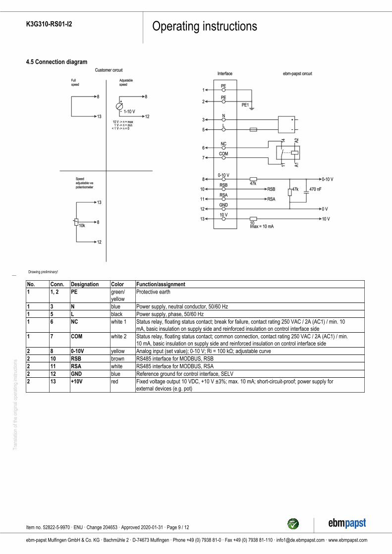
4.5 Connection diagram
Drawing preliminary!
No. Conn. Designation Color Function/assignment1 1, 2 PE green/
yellowProtective earth
1 3 N blue Power supply, neutral conductor, 50/60 Hz1 5 L black Power supply, phase, 50/60 Hz1 6 NC white 1 Status relay, floating status contact; break for failure, contact rating 250 VAC / 2A (AC1) / min. 10
mA, basic insulation on supply side and reinforced insulation on control interface side1 7 COM white 2 Status relay, floating status contact; common connection, contact rating 250 VAC / 2A (AC1) / min.
10 mA, basic insulation on supply side and reinforced insulation on control interface side2 8 0-10V yellow Analog input (set value); 0-10 V; Ri = 100 kΩ; adjustable curve2 10 RSB brown RS485 interface for MODBUS, RSB2 11 RSA white RS485 interface for MODBUS, RSA2 12 GND blue Reference ground for control interface, SELV2 13 +10V red Fixed voltage output 10 VDC, +10 V ±3%; max. 10 mA; short-circuit-proof; power supply for
external devices (e.g. pot)
Item no. 52822-5-9970 · ENU · Change 204653 · Approved 2020-01-31 · Page 9 / 12
ebm-papst Mulfingen GmbH & Co. KG · Bachmühle 2 · D-74673 Mulfingen · Phone +49 (0) 7938 81-0 · Fax +49 (0) 7938 81-110 · [email protected] · www.ebmpapst.com
Operating instructionsK3G310-RS01-I2Tr
ansl
atio
n of
the
orig
inal
ope
ratin
g in
stru
ctio
ns
4.6 Checking connections
; Ensure isolation from supply (all phases).
; Make sure a restart is impossible
; Check the cables for proper fit.
4.7 Switching on the device
The device may only be switched on if it has been installed properly andin accordance with its intended use, including the required safetymechanisms and professional electrical hookup. This also applies fordevices which have already been equipped with plugs and terminals orsimilar connectors by the customer.
WARNINGHot motor housingRisk of fire
→ Ensure that no combustible or flammable materials arelocated close to the fan.
; Before switching on, check the device for visible external damageand make sure the protective devices are functional.
; Check the fan's air flow paths for foreign matter and remove anyforeign matter found.
; Apply the nominal supply voltage.
; Start the device by changing the input signal.
NOTEDamage to the device from vibrationBearing damage, shorter service life
→ Low-vibration operation of the fan must be ensured over theentire speed control range.
→ Severe vibration can arise for instance from inexperthandling, transportation damage and resultant imbalance orbe caused by component or structural resonance.
→ Speed ranges with excessively high vibration levels andpossibly resonant frequencies must be determined in thecourse of fan commissioning.
→ Either run through the resonant range as quickly aspossible with speed control or find another remedy.
→ Operation with excessively high vibration levels canlead to premature failure.
→ The maximum permissible vibration severity must notexceed 3.5 mm/s and should be checked at intervals of 6months. #It is to be determined at the motor mount at themotor support plate at least in axial direction andtransversely to this. #Measurement of the vibration in allthree axes is recommended and should be performed overthe entire speed range in order to obtain a complete picture ofthe vibrations occurring in the application, see Chapter 6.Maintenance, malfunctions, possible causes and remedies.
4.8 Switching off the device
Switching off the device during operation:
; Switch off the device via the control input.
; Do not switch the motor (e.g. in cyclic operation) on and off via powersupply.
Switching off the device for maintenance:
; Switch off the device via the control input.
; Do not switch the motor (e.g. in cyclic operation) on and off via powersupply.
; Disconnect the device from the power supply.
; When disconnecting, be sure to disconnect the ground connection last.
5. INTEGRATED PROTECTIVE FEATURES
The integrated protective functions cause the motor to switch offautomatically in the event of the faults described in the table.
Fault Safety feature description/function
Rotor position detection error An automatic restart follows.Blocked rotor ; After the blockage is
removed, the motor restartsautomatically.
Line undervoltage (line voltageoutside of permitted nominalvoltage range)
; If the line voltage returns topermitted values, the motorrestarts automatically.
6. MAINTENANCE, MALFUNCTIONS, POSSIBLECAUSES AND REMEDIES
Do not perform any repairs on your device. Send the device to ebm-papst for repair or replacement.
WARNINGLive terminals and connections even with deviceswitched offElectric shock
→ Wait five minutes after disconnecting the voltage at all polesbefore opening the device.
CAUTIONIf control voltage or a stored speed set value is applied,the motor will restart automatically, e.g. after a powerfailure.Risk of injury
→ Keep out of the device’s danger zone.
→ When working on the device, switch off the line voltageand ensure that it cannot be switched back on.
→ Wait until the device comes to a stop.
→ After working on the device, remove any tools or otherobjects from the device.
NOTEIf the device is not operated for a lengthy period in installedcondition in a dry environment, it is to be started up andoperated at full speed for one hour at least every four months. Ifthe device is not operated for a lengthy period in installedcondition in a damp environment (e.g. outdoors), it is to bestarted up and operated at full speed for at least two hours oncea month to move the bearings and allow any condensate thatmay have ingressed to evaporate.
Malfunction/fault Possible cause Possible remedy
Item no. 52822-5-9970 · ENU · Change 204653 · Approved 2020-01-31 · Page 10 / 12
ebm-papst Mulfingen GmbH & Co. KG · Bachmühle 2 · D-74673 Mulfingen · Phone +49 (0) 7938 81-0 · Fax +49 (0) 7938 81-110 · [email protected] · www.ebmpapst.com
Operating instructionsK3G310-RS01-I2Tr
ansl
atio
n of
the
orig
inal
ope
ratin
g in
stru
ctio
ns
Impeller notrunning smoothly
Imbalance in rotatingparts
Clean the device;replace it if imbalancepersists after cleaning.Make sure noweight clips areremoved duringcleaning.
Motor not turning Mechanical blockage Switch off, isolatefrom supply andremove mechanicalblockage.
Line voltage faulty Check line voltage,restore powersupply, apply controlsignal.
Faulty connection Isolate from supply,correct connection;see connectiondiagram.
Motor/electronicsovertemperature
Deficient cooling Improve cooling. Letthe device cool down.To reset the errormessage, switch offthe line voltage for atleast 25 s and thenswitch it on again.
Thermal overloadprotector activated
Allow motor to cooloff, locate and rectifycause of error,release restart lockoutif necessary
Ambient temperaturetoo high
Reduce the ambienttemperature.Reset by reducingcontrol input to 0.
Impermissible point ofoperation
Correct the operatingpoint. Let the devicecool down.
In the event of further malfunctions, contact ebm-papst.
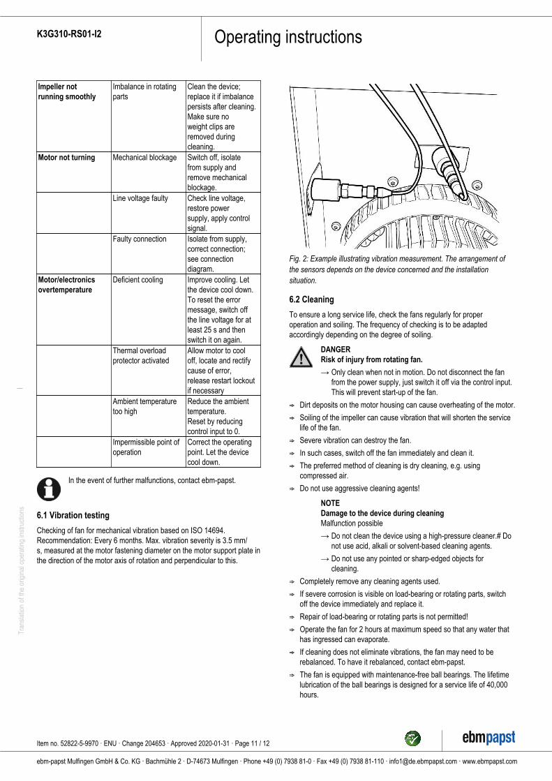
6.1 Vibration testing
Checking of fan for mechanical vibration based on ISO 14694.Recommendation: Every 6 months. Max. vibration severity is 3.5 mm/s, measured at the motor fastening diameter on the motor support plate inthe direction of the motor axis of rotation and perpendicular to this.
Fig. 2: Example illustrating vibration measurement. The arrangement ofthe sensors depends on the device concerned and the installationsituation.
6.2 Cleaning
To ensure a long service life, check the fans regularly for properoperation and soiling. The frequency of checking is to be adaptedaccordingly depending on the degree of soiling.
DANGERRisk of injury from rotating fan.
→ Only clean when not in motion. Do not disconnect the fanfrom the power supply, just switch it off via the control input.This will prevent start-up of the fan.
; Dirt deposits on the motor housing can cause overheating of the motor.
; Soiling of the impeller can cause vibration that will shorten the servicelife of the fan.
; Severe vibration can destroy the fan.
; In such cases, switch off the fan immediately and clean it.
; The preferred method of cleaning is dry cleaning, e.g. usingcompressed air.
; Do not use aggressive cleaning agents!
NOTEDamage to the device during cleaningMalfunction possible
→ Do not clean the device using a high-pressure cleaner.# Donot use acid, alkali or solvent-based cleaning agents.
→ Do not use any pointed or sharp-edged objects forcleaning.
; Completely remove any cleaning agents used.
; If severe corrosion is visible on load-bearing or rotating parts, switchoff the device immediately and replace it.
; Repair of load-bearing or rotating parts is not permitted!
; Operate the fan for 2 hours at maximum speed so that any water thathas ingressed can evaporate.
; If cleaning does not eliminate vibrations, the fan may need to berebalanced. To have it rebalanced, contact ebm-papst.
; The fan is equipped with maintenance-free ball bearings. The lifetimelubrication of the ball bearings is designed for a service life of 40,000hours.
Item no. 52822-5-9970 · ENU · Change 204653 · Approved 2020-01-31 · Page 11 / 12
ebm-papst Mulfingen GmbH & Co. KG · Bachmühle 2 · D-74673 Mulfingen · Phone +49 (0) 7938 81-0 · Fax +49 (0) 7938 81-110 · [email protected] · www.ebmpapst.com
Operating instructionsK3G310-RS01-I2Tr
ansl
atio
n of
the
orig
inal
ope
ratin
g in
stru
ctio
ns
; If bearing replacement is necessary after that period, contact ebm-papst.
; Adapt the maintenance intervals to the actual level of dust exposure.
6.3 Safety inspection
NOTEHigh-voltage testThe integrated EMC filter has Y capacitors. The tripping currentis exceeded when AC testing voltage is applied.
→ Test the device with DC voltage when you perform thelegally required high-voltage test. The voltage to be usedcorresponds to the peak value of the AC voltage required bythe standard.
What to check How to check How often What action?Contactprotectioncover forintactness ordamage
Visual inspection At least every6 months
Repair orreplacement ofdevice
Device fordamage toblades andhousing
Visual inspection At least every6 months
Replacement ofdevice
Fastening thecables
Visual inspection At least every6 months
Fasten
Fastening theprotective earthterminal
Visual inspection At least every6 months
Fasten
Insulation ofcables fordamage
Visual inspection At least every6 months
Replace cables
Impeller forwear/deposits/corrosion anddamage
Visual inspection At least every6 months
Clean impelleror replace device
Condensationdrainage holesfor clogging,where necessary
Visual inspection At least every6 months
Open holes
Abnormalbearing noise
acoustic At least every6 months
Replace device
Vibration test Vibration tester,start-up ordecelerationmeasurement
Recommendedevery 6 months
Clean impelleror replace device
6.4 Disposal
For ebm-papst, environmental protection and resource preservation aretop priority corporate goals.ebm-papst operates an environmental management system which iscertified in accordance with ISO 14001 and rigorously implementedaround the world on the basis of German standards.Right from the development stage, ecological design, technical safetyand health protection are fixed criteria.The following section contains recommendations for ecological disposalof the product and its components.
6.4.1 Country-specific legal requirements
NOTECountry-specific legal requirementsAlways observe the applicable country-specific legalregulations with regard to the disposal of products or wasteoccurring in the various phases of the life cycle. Thecorresponding disposal standards are also to be heeded.
6.4.2 Disassembly
Disassembly of the product must be performed or supervised byqualified personnel with the appropriate technical knowledge.The product is to be disassembled into suitable components for disposalemploying standard procedures for motors.
WARNINGHeavy parts of the product may drop off. Some of theproduct components are heavy. These componentscould drop off during disassembly.This can result in fatal or serious injury and material damage.
→ Secure components before unfastening to stop them falling.
6.4.3 Component disposal
The products are mostly made of steel, copper, aluminum and plastic.Metallic materials are generally considered to be fully recyclable.Separate the components for recycling into the following categories:
● Steel and iron
● Aluminum
● Non-ferrous metal, e.g. motor windings
● Plastics, particularly with brominated flame retardants, in accordancewith marking
● Insulating materials
● Cables and wires
● Electronic scrap, e.g. circuit boards
Only ferrite magnets and not rare earth magnets are used in externalrotor motors from ebm-papst Mulfingen GmbH & Co. KG.
; Ferrite magnets can be disposed of in the same way as normal ironand steel.
Electrical insulating materials on the product, in cables and wires aremade of similar materials and are therefore to be treated in the samemanner.The materials concerned are as follows:
● Miscellaneous insulators used in the terminal box
● Power cables
● Cables for internal wiring
● Electrolytic capacitors
Dispose of electronic components employing the proper procedures forelectronic scrap.
→ Please contact ebm-papst for any other questions on disposal.
Item no. 52822-5-9970 · ENU · Change 204653 · Approved 2020-01-31 · Page 12 / 12
ebm-papst Mulfingen GmbH & Co. KG · Bachmühle 2 · D-74673 Mulfingen · Phone +49 (0) 7938 81-0 · Fax +49 (0) 7938 81-110 · [email protected] · www.ebmpapst.com