Embed Size (px)
Citation preview

USER’S MANUAL
1/32 DIN Digital Panel MeterK3GN
Cat. No. N102-E1-04

I
PREFACE
This User’s Manual provides you with information necessary for use of the K3GN series of digital panel meters. Please read this manual carefully to ensure correct and efficient use of the product. Keep this manual handy for future reference.
General Precautions If contemplating using the product in the following environments or for the following equipment, first contact a sales representative of the company and then accept responsibility for incorporating into the design fail-safe operation, redundancy, and other appropriate measures for ensuring reliability and safety of the equipment and the overall system.
(1) Environments deviating from those specified in this manual
(2) Nuclear power control systems, traffic (rail car/automobile/aircraft) control systems, medical equipment, amusement equipment, and rescue and security equipment
(3) Other equipment that demands high reliability, including those related to the safety of life and property
About the Contents of the Manual
(1) Any reproduction, full or in part, of the manual is prohibited without prior written permission from the company.
(2) Specifications in the manual may be subject to change without notice. (3) Information in the manual has been carefully checked for accuracy. If finding any
suspicious or erroneous descriptions in the manual, however, you are kindly requested to contact a branch office of the company. In such a case, please let us know the Cat. No. shown on the front cover of the manual.
II
Other Informations
1 Warranty (1) Warranty Period
The warranty period for an OMRON Product is one year from either the date of purchase or the date on which the OMRON Product is delivered to the specified location.
(2) Extent of Warranty If an OMRON Product is subject to a failure for which OMRON is responsible during the warranty period, either a replacement product will be provided or the defective product will be repaired free of charge at the place of purchase, This warranty, however, will not cover problems that occur as a result of any of the following. a) Using the OMRON Product under conditions or in an environment not described in catalogs or in the
specifications, or not operating the OMRON Product according to the instructions contained in catalogs or in the specifications.
b) Problems caused by something other than the OMRON Product. c) Modifications or repairs performed by a party other than OMRON. d) Using the OMRON Product for other than its designed purpose. e) Problems that could not have been foreseen with the level of science and technology that existed at the time
the OMRON Product was shipped. f) Problems caused by an Act of God or other circumstances for which OMRON is not responsible. This warranty covers only the OMRON Product itself. It does not cover any other damages that may occur directly as a result of a problem with the OMRON Product.
2 Limitations of Liability
(1) OMRON shall not be responsible for special, indirect, or consequential damages originating in an OMRON Product.
(2) For programmable OMRON Products, OMRON does not accept responsibility for any programming that is performed by a party than OMRON, or for any results arising from that programming.
3 Applicable Conditions
(1) When using OMRON Products in combination with other products, it is use’s responsibility to confirm the suitability of the OMRON Products for the system, devices, and equipment that are being used. OMRON accepts no responsibility for the suitability of OMRON Products used in combination with other products.
(2) When using OMRON Products in any of the following applications, consult an OMRON representative and check specifications to allow sufficient leeway in ratings and performance, and to implement suitable safety measures, such as safety circuits, to minimize danger in the event of an accident. a) Outdoor applications, applications with potential for chemical contamination or electrical interference, or
application under conditions or environments not described in catalogs. b) Nuclear control systems, railroad systems, aviation systems, vehicles, combustion systems, medical equipment,
amusement machines, or equipment regulated by government or Industrial standards. c) Other systems, machines, and equipment that may have a serious influence on human life and property. d) Equipment requiring a high level of reliability, such as gas, water, or electrical supply systems, and systems that
operate 24 hours a day. e) Other applications requiring a high level of safety, corresponding to points a) to d), above.
(3) When OMRON Products are used in an application that could pose significant risk to human life or property, the overall system must be designed so that the required safety can be ensured by providing notice of the danger and incorporating redundancy into the design. Make sure that OMRON Products are appropriately wired and mounted to serve their intended purpose in the overall system.
(4) Application examples provided in catalogs are for reference only. Confirm functionality and safety before actually using the devices and equipment.
(5) To prevent unexpected problems from arising due to the OMRON Product being used incorrectly by the customer or any other party, make sure that you understand and carefully observe all of the relevant prohibitions and precautions.
4 Changes to Specifications Specifications and accessories to the products in catalogs may be changed as needed to improve the products or for any other reason. Check with your OMRON representative for the actual specifications for OMRON Products at the time of purchase.
5 Applicability The above information assumes that business and product application will be conducted in Japan. For business and application outside of Japan, consult with your OMRON representative.

III
Signal Words and Safety Notices
Signal Words
In this manual, safety notices are divided into WARNING and CAUTION according to the hazard level.
As both of WARNING and CAUTION notices contain important information for ensuring safety, be sure to observe them.
Symbols
CAUTION A signal word indicating a potentially hazardous situation which, if not avoided, may result in minor or moderate injury or property damage.
Indicates a CAUTION or WARNING with the specific contents indicated in the triangle and described in text. The example at the left is for a general precaution.
Indicates a prohibition with the specific contents described in text, which is general unless otherwise classified.
Indicates a prohibition with the specific contents indicated behind the circle and slash and described in text. The example at the left is for prohibiting disassembling.
Indicates a mandatory action with the specific contents indicated in the circle and described in text. The example at the left is for a general mandatory action that is not classified otherwise.
IV
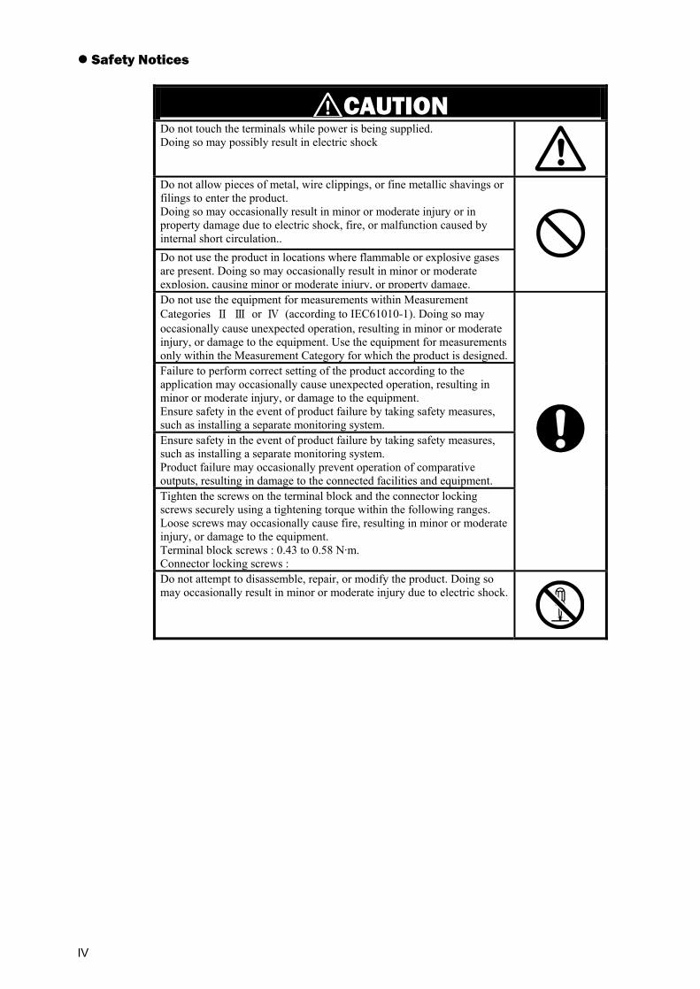
Safety Notices
CAUTION
Do not touch the terminals while power is being supplied. Doing so may possibly result in electric shock
Do not allow pieces of metal, wire clippings, or fine metallic shavings or filings to enter the product. Doing so may occasionally result in minor or moderate injury or in property damage due to electric shock, fire, or malfunction caused by internal short circulation.. Do not use the product in locations where flammable or explosive gases are present. Doing so may occasionally result in minor or moderate explosion, causing minor or moderate injury, or property damage.
Do not use the equipment for measurements within Measurement Categories Ⅱ Ⅲ or Ⅳ (according to IEC61010-1). Doing so may occasionally cause unexpected operation, resulting in minor or moderate injury, or damage to the equipment. Use the equipment for measurements only within the Measurement Category for which the product is designed.Failure to perform correct setting of the product according to the application may occasionally cause unexpected operation, resulting in minor or moderate injury, or damage to the equipment. Ensure safety in the event of product failure by taking safety measures, such as installing a separate monitoring system. Ensure safety in the event of product failure by taking safety measures, such as installing a separate monitoring system. Product failure may occasionally prevent operation of comparative outputs, resulting in damage to the connected facilities and equipment. Tighten the screws on the terminal block and the connector locking screws securely using a tightening torque within the following ranges. Loose screws may occasionally cause fire, resulting in minor or moderate injury, or damage to the equipment. Terminal block screws : 0.43 to 0.58 N·m. Connector locking screws :
Do not attempt to disassemble, repair, or modify the product. Doing so may occasionally result in minor or moderate injury due to electric shock.
V
Precautions for Safe Use Precautions for the environment.
(1) Do not use the product in the following locations. • Locations subject to direct radiant heat from heating equipment • Locations here the product may come into contact with water or oil • Locations subject to direct sunlight • Locations where dust or corrosive gases (in particular, sulfuric or ammonia gas) are
present • Locations subject to extreme temperature changes • Locations where icing or condensation may occur • Locations subject to excessive shocks or vibration
(2) Do not use the product in locations subject to temperatures or humidity levels outside the specified ranges or in locations prone to condensation. If the product is installed in a panel, ensure that the temperature around the product (not the temperature around the panel) does not go outside the specified range. Parts life is dependent on temperatures. A part life shortens when the temperature rises, and it lengthens when the temperature falls. Parts life can be lengthened by lowering the temperature inside the product.
(3) In order to prevent inductive noise, wire the lines connected to the product separately from power lines carrying high voltages or currents. Do not wire in parallel with or in the same cable as power lines. Other measures for reducing noise include running lines along separate ducts and using shield lines.
(4) Do not install the product near devices generating strong high-frequency waves or surges. When using a noise filter, check the voltage and current and install it as close to the product as possible. If several products are mounted side-by-side or arranged in a vertical line, the heat dissipation will cause the internal temperature of the product to rise, shortening the service life. If necessary, cool the products using a fan or other cooling method.
(5) Take care when cleaning the product, because the exterior of the product contains organic solvent (thinner, benzine, etc.), strong alkaline material and strong acid material.
(6) Avoid storing in high humidity or in a corrosive gas environment (including during transportation)
Precautions for Safe Use.
(1) Use and store within the proper temperature and humidity described in the specifications.
(2) Provide sufficient space around the product for heat dissipation.
(3) When using the product stored unused over a year after purchasing, the product features may not be utilized sufficiently.
(4) Avoid storing outdoors and in a place that receives direct sunlight (including during transportation).
(5) The service life of the output relays depends on the switching capacity and switching conditions. Consider the actual application conditions and use the product within the rated load and electrical service life. Using the product beyond its service life may result in contact welding or burning.
(6) Be sure to confirm the name and polarity for each terminal before wiring the terminal block and connectors. Faulty wiring causes destruction or burnout of internal parts.
(7) Use the product within the noted supply voltage and rated load.
(8) Do not connect anything to unused terminals.
(9) Output turns OFF when the mode is changed or settings are initialized. Take this into consideration when setting up the control system.

VI
(10) Install an external switch or circuit breaker and label them clearly so that the operator can quickly turn OFF the power.
(11) Ensure that the rated voltage is achieved no longer than 2 s after turning the power ON. When applying a voltage gradually, power supply may not be reset or output functions indeterminately.
(12) Mount to a panel between 1 and 5 mm thick.
(13) Use the specified size of crimp terminals (M3, width : 5.8 mm max.) for wiring. To connect bare wires, use AWG 28 to AWG 16 to wire the power supply terminals and AWG 22 to AWG 14 for other terminals. (Length of exposed wire : 6 to 8 mm)
(14) Allow the product to operate without load for at least 15 minutes after the power is turned ON.
VII
Precautions for Correct Use
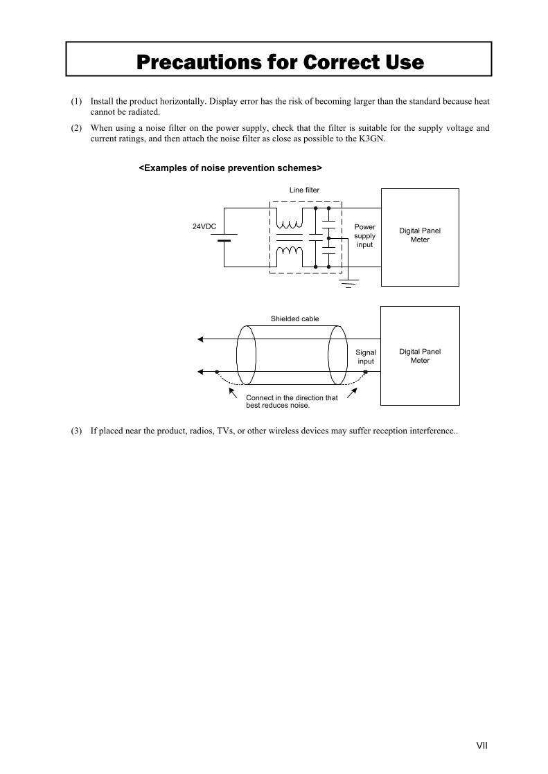
(1) Install the product horizontally. Display error has the risk of becoming larger than the standard because heat cannot be radiated.
(2) When using a noise filter on the power supply, check that the filter is suitable for the supply voltage and current ratings, and then attach the noise filter as close as possible to the K3GN.
<Examples of noise prevention schemes>
(3) If placed near the product, radios, TVs, or other wireless devices may suffer reception interference..
Power supply input
Digital PanelMeter
24VDC
Line filter
Digital PanelMeter
Shielded cable
Signal input
Connect in the direction that best reduces noise.

VIII
Alphabetic Characters for Setting Data
This manual uses the following alphabetic characters for setting data.
a b c d e f g h i j k l m
A B C D E F G H I J K L M
n o p q r s t u v w x y z
N O P Q R S T U V W X Y Z
IX
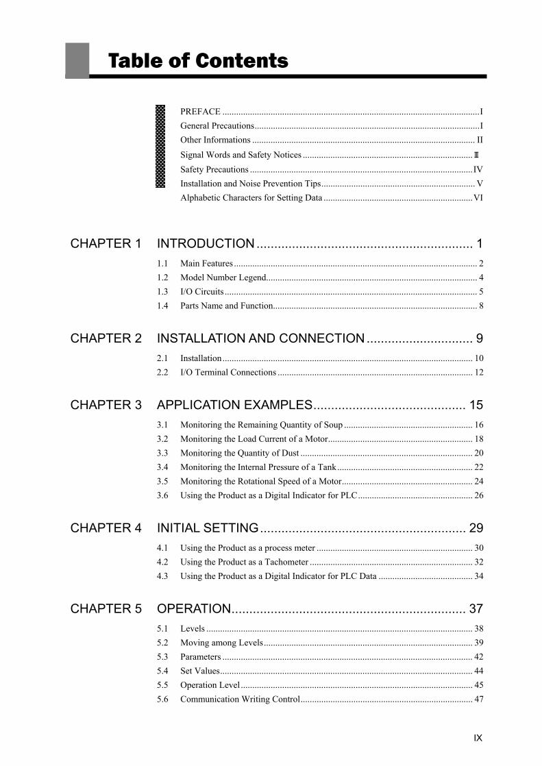
Table of Contents
PREFACE ................................................................................................................I General Precautions..................................................................................................I Other Informations ................................................................................................. II
Signal Words and Safety Notices ..........................................................................Ⅲ Safety Precautions .................................................................................................IV Installation and Noise Prevention Tips................................................................... V Alphabetic Characters for Setting Data .................................................................VI
CHAPTER 1 INTRODUCTION............................................................. 1 1.1 Main Features .......................................................................................................... 2 1.2 Model Number Legend............................................................................................ 4 1.3 I/O Circuits .............................................................................................................. 5 1.4 Parts Name and Function......................................................................................... 8
CHAPTER 2 INSTALLATION AND CONNECTION.............................. 9 2.1 Installation............................................................................................................. 10 2.2 I/O Terminal Connections ..................................................................................... 12
CHAPTER 3 APPLICATION EXAMPLES........................................... 15 3.1 Monitoring the Remaining Quantity of Soup ........................................................ 16 3.2 Monitoring the Load Current of a Motor............................................................... 18 3.3 Monitoring the Quantity of Dust ........................................................................... 20 3.4 Monitoring the Internal Pressure of a Tank........................................................... 22 3.5 Monitoring the Rotational Speed of a Motor......................................................... 24 3.6 Using the Product as a Digital Indicator for PLC.................................................. 26
CHAPTER 4 INITIAL SETTING.......................................................... 29 4.1 Using the Product as a process meter .................................................................... 30 4.2 Using the Product as a Tachometer ....................................................................... 32 4.3 Using the Product as a Digital Indicator for PLC Data ......................................... 34
CHAPTER 5 OPERATION.................................................................. 37 5.1 Levels .................................................................................................................... 38 5.2 Moving among Levels........................................................................................... 39 5.3 Parameters ............................................................................................................. 42 5.4 Set Values.............................................................................................................. 44 5.5 Operation Level ..................................................................................................... 45 5.6 Communication Writing Control........................................................................... 47

X
5.7 Key Protect Setting ................................................................................................48 5.8 Selecting an Input Type .........................................................................................50 5.9 Selecting an Analog Range....................................................................................51 5.10 Selecting an Input-pulse Frequency Range............................................................52 5.11 Specifying the Scaling Factor for Analog Input/Digital Data Display...................53 5.12 Specifying the Scaling Factor for Input Pulse Frequency......................................55 5.13 Specifying the Decimal Point Position ..................................................................58 5.14 Selecting the Output Operating Action ..................................................................59 5.15 Performing Linear Output......................................................................................60 5.16 Specifying Communication Parameters .................................................................63 5.17 Clearing All Parameters .........................................................................................65 5.18 Specifying the Number of Measurements for Averaging ......................................66 5.19 Specifying the Function of the Event Input ...........................................................67 5.20 Specifying the Hysteresis.......................................................................................69 5.21 Specifying the Auto-zero Time..............................................................................71 5.22 Specifying the Startup Compensation Time ..........................................................73 5.23 Changing the Display Color...................................................................................75 5.24 Changing the Display Auto-return Time................................................................77 5.25 Changing the Move-to-Protect-Level Time ...........................................................79 5.26 Changing the Send Waiting Time..........................................................................81
CHAPTER 6 FUNCTION DESCRIPTION .......................................... 83 6.1 Measurement..........................................................................................................84 6.2 Scaling ...................................................................................................................86 6.3 Auto-zero/Startup Compensation...........................................................................88 6.4 Average Processing................................................................................................89 6.5 Event Input/Pulse Input..........................................................................................90 6.6 Process Value Hold................................................................................................91 6.7 Forced-zero ............................................................................................................92 6.8 Comparative Output...............................................................................................93 6.9 Hysteresis...............................................................................................................94 6.10 Display Color Change............................................................................................95
CHAPTER 7 COMMUNICATIONS ..................................................... 97 7.1 Communication Protocols......................................................................................98 7.2 Data Format Structure............................................................................................99 7.3 Structure of Command/Response Text ................................................................101 7.4 Variable Area.......................................................................................................102 7.5 Read from Variable Area ...................................................................................103 7.6 Write to Variable Area .......................................................................................104 7.7 Operation Instructions..........................................................................................105 7.8 Setting Areas........................................................................................................106 7.9 Commands and Responses...................................................................................107 7.10 Variable Area Map...............................................................................................115 7.11 Communications Control Flow............................................................................118 7.12 Programming Example ........................................................................................123

XI
CHAPTER 8 USER CALIBRATION.................................................. 127 8.1 User Calibration .................................................................................................. 128 8.2 User Calibration Processes .................................................................................. 130
CHAPTER 9 TROUBLESHOOTING GUIDE.................................... 133 9.1 Error Indications.................................................................................................. 134 9.2 Troubleshooting Table......................................................................................... 135
APPENDIX ...................................................................137 Specifications ............................................................................................ 138 Parameter List............................................................................................ 142 ASCII Code Table...................................................................................... 143

1.1 Main Features
1
INTRODUCTION 1 INTRODUCTION
1.1 Main Features ・・・・・・・・・・・・・・・・・・・・・・・・・・・・・・・・・・・・・・・・・・・・ 2 1.2 Model Number Legend ・・・・・・・・・・・・・・・・・・・・・・・・・・・・・・・・・・・・ 4 1.3 I/O Circuits ・・・・・・・・・・・・・・・・・・・・・・・・・・・・・・・・・・・・・・・・・・・・・・ 5
Input Circuit Diagrams/Output Circuit Diagrams/ Internal Block Diagram
1.4 Parts Name and Function ・・・・・・・・・・・・・・・・・・・・・・・・・・・・・・・・・・ 8
This chapter provides an overview of the product.
CHAPTER
CHAPTER 1 INTRODUCTION
2
INTR
ODUC
TION
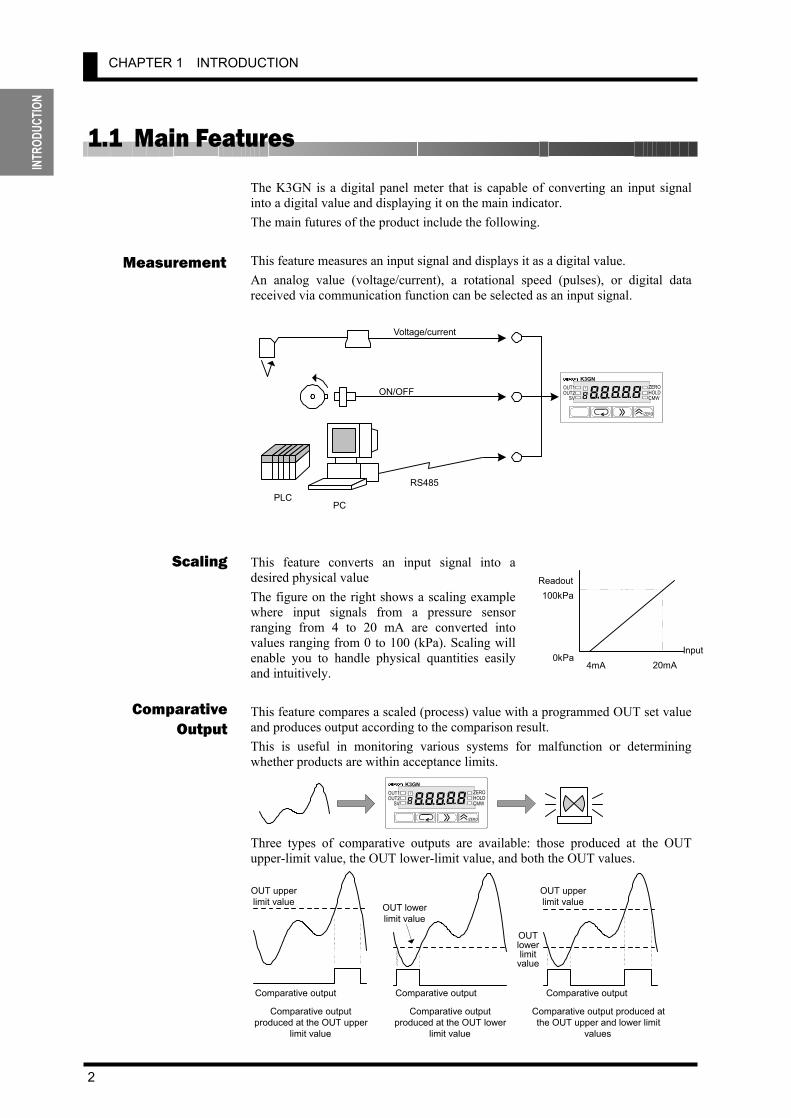
1.1 Main Features The K3GN is a digital panel meter that is capable of converting an input signal into a digital value and displaying it on the main indicator. The main futures of the product include the following. This feature measures an input signal and displays it as a digital value. An analog value (voltage/current), a rotational speed (pulses), or digital data received via communication function can be selected as an input signal.
This feature converts an input signal into a desired physical value The figure on the right shows a scaling example where input signals from a pressure sensor ranging from 4 to 20 mA are converted into values ranging from 0 to 100 (kPa). Scaling will enable you to handle physical quantities easily and intuitively.
This feature compares a scaled (process) value with a programmed OUT set value and produces output according to the comparison result. This is useful in monitoring various systems for malfunction or determining whether products are within acceptance limits.
Three types of comparative outputs are available: those produced at the OUT upper-limit value, the OUT lower-limit value, and both the OUT values.
Measurement
ComparativeOutput
Scaling
4mA 20mA
100kPa
0kPaInput
Readout
Comparative output produced at the OUT lower
limit value
Comparative output produced atthe OUT upper and lower limit
values
OUT upperlimit value
Comparative output
Comparative outputproduced at the OUT upper
limit value
OUT lowerlimit value
OUT upperlimit value
OUT lower limit
value
Comparative output Comparative output
PLCPC
Voltage/current
ON/OFF
RS485
K3GN
/ZERO
ZEROHOLD
OUT1((8
T
(8( CMWOUT2
SV
K3GN
/ZERO
ZERO HOLD OUT1
((8T
(8( CMW OUT2SV

1.1 Main Features
3
INTRODUCTION
This feature enables a process value to be held while the external event input stays ON. The outputs are also retained. This feature shifts a process value to zero, and can be used to evaluate and display the deviation of a process value from a reference value. The forced-zero function can be activated by using the ZERO/ key on the front panel, via the event input terminal, or communications.
This feature allows programming of the display color. In the example shown below, the display color is programmed so that it changes from green to red when a comparative output turns ON. The display color can also be programmed so that it changes red to green or is fixed to red or green.
This feature allows the host PC to read process values from the product or read/write various parameter settings from/to the host PC. The host PC provides logging of measured data and remote control to the product.
Communi-cation
ProcessValue Hold
Forced-zero
Display Color Change
((((88
T
((((88
T
((((88
T
485 232C
Processvalue
HOLD input
1*0058
T
OUT2 value
OUT1 value 1!2368
T
1(7818
T
Green
Red
Red
Processvalue
ZERO input
Forced-zero value(shifted value)
Measurement valueafter executing theforced-zero function

CHAPTER 1 INTRODUCTION
4
INTR
ODUC
TION
1.2 Model Number Legend
1. Input Type
ND: DC voltage/current, NPN PD: DC voltage/current, PNP
2. Output Type C: 2 relay contact outputs (SPST-NO) C-FLK: 2 relay contact outputs (SPST-NO) and RS-485 C-L1: 2 relay contact outputs (SPST-NO) and DC current (0 to 20 mA, 4 to 20 mA) C-L2: 2 relay contact outputs (SPST-NO) and DC voltage (0 to 5 V, 1 to 5 V, 0 to 10 V) T1: 3 transistor outputs (NPN open collector) T1-FLK: 3 transistor outputs (NPN open collector) and RS-485 T1-L1: 3 transistor outputs (NPN open collector) and DC current (0 to 20 mA, 4 to 20 mA) T1-L2: 3 transistor outputs (NPN open collector) and DC voltage (0 to 5 V, 1 to 5 V, 0 to 10 V) T2: 3 transistor outputs (PNP open collector) T2-FLK: 3 transistor outputs (PNP open collector) and RS-485
3. Option None: None -400: Normally energized relays
4. Supply Voltage 24 VDC: 24 VDC
List of Models Output type Supply
voltage Input type Judgement output Data transmission output Model
None K3GN-NDC 24 VDC RS-485 K3GN-NDC-FLK 24 VDC DC current (0 to 20 mA, 4 to 20 mA) K3GN-NDC-L1 24 VDC
2 relay contact outputs (SPST-NO)
DC voltage (0 to 5 V, 1 to 5 V, 0 to 10 V) K3GN-NDC-L2 24 VDC
None K3GN-NDC-400 24 VDC RS-485 K3GN-NDC-FLK-400 24 VDCDC current (0 to 20 mA, 4 to 20 mA) K3GN-NDC-L1-400 24 VDC
2 relay contact outputs (SPST-NO) Normally energized relays (See note.) DC voltage (0 to 5 V,
1 to 5 V, 0 to 10 V) K3GN-NDC-L2-400 24 VDC
None K3GN-NDT1 24 VDC RS-485 K3GN-NDT1-FLK 24 VDC DC current (0 to 20 mA, 4 to 20 mA) K3GN-NDT1-L1 24 VDC
DC voltage, DC current, or NPN input
3 transistor outputs (NPN open collector)
DC voltage (0 to 5 V, 1 to 5 V, 0 to 10 V) K3GN-NDT1-L2 24 VDC
None K3GN-PDC 24 VDC 2 relay contact outputs (SPST-NO) RS-485 K3GN-PDC-FLK 24 VDC
None K3GN-PDT2 24 VDC
24 VDC
DC voltage, DC current, or PNP input
3 transistor outputs (PNP open collector) RS-485 K3GN-PDT2-FLK 24 VDC
Note: Refer to page 6 for information on models with normally energized relays.

1.3 I/O Circuits
5
INTRODUCTION
1.3 I/O Circuits Input Circuit Diagrams
Analog Input
Event Input/Pulse Input
Output Circuit Diagrams
Contact Output
Voltage input Current input
NPN input PNP input
1
3
2
2.35KΩ
4.7KΩ
24VDC-
HOLD/ZERO Pulse
24VDC+ 1
3
2
2.35KΩ
4.7KΩ
24VDC-
24VDC+
HOLD/ZERO Pulse
12
11
9
COM
OUT2
OUT1 5V
5V
-
+A
B
ADVoltage
COM
4
5
-
+
60Ω
ADCurrent
COM
6
5 A+B = 1MΩ
To To

CHAPTER 1 INTRODUCTION
6
INTR
ODUC
TION
Models with Normally Energized Relays K3GN-NDC-@-400 24 VDC
• The drive operation for the output relay is reversed in these models.
• Relay contacts can be made open (i.e., OFF) when comparative set values are being judged. This is effective when constructing systems that take failsafe measures into consideration.
List of Models Models with Normally Energized Relays
K3GN-NDC-400 24 VDC K3GN-NDC-FLK-400 24 VDC K3GN-NDC-L1-400 24 VDC K3GN-NDC-L2-400 24 VDC
Transistor Output
Linear Output
Relation between Output Type and Relay Output Operation
L 5KΩ min. L 500Ω max.
7
8
+
-
+
-
7
8
+
- +
-
NPN output PNP output
11
12
10
9
COM
OUT2
PASS
OUT1
8.2Ω
8.2Ω
8.2Ω
8.2Ω
11
12
10
9
COM
OUT2
PASS
OUT1
8.2Ω
8.2Ω
Note: If Upper/Lower Limit is selected, the upper limit and lower limit for the comparative set value can be set individually and will be displayed for OUT1 and OUT2.
Linear current outputLinear voltage output

1.3 I/O Circuits
7
INTRODUCTION
Internal Block Diagram
Microcomputer
Drive circuit
Key Display
ADconvertorInput circuit
EEPROM
Communi-cation driver Waveform
recitification circuit
Constant-voltage circuit 1
Control input circuit
Drive circuit
Drive circuit Output
Constant-voltage circuit 2
Power supply circuit
Operationpower supply
Event input/ pulse input
terminal
Communi-cation
terminal
Contactoutput
Transistoroutput
Analog input terminal
*4
*2
*3
*1 Available only for the product with transistor output *2 Available only for the product with relay output *3 Available only for the product with communication interface
Drive circuit Output circuit
circuit
Linear current/ Voltage output
*4 Available only for the product with linear current/voltage output

CHAPTER 1 INTRODUCTION
8
INTR
ODUC
TION
1.4 Parts Name and Function
Name Function Main indicator Displays a process value, parameter code, or set value.
OUT1 (Comparative output 1)
Is on when comparative output 1 is ON, and off when comparative output 1 is OFF.
OUT2 (Comparative output 2)
Is on when comparative output 2 is ON, and off when comparative output 2 is OFF.
SV (Set value)
Stays on while a set value is displayed or being changed, and off at all other times.
T (Teaching)
Stays on while a set value that can be taught is displayed, and blinks during teaching. At the calibration level, stays on while a calibration value is displayed, and blinks while the calibration value is read. Stays off at all other times.
ZERO (Forced-zero)
Is on when zero-shifting by forced-zero operation is active. Turns off when forced-zero operation is canceled.
HOLD (Process value hold) Stays on while the process value is held, and off at all other times.
Operation indicator sections
CMW (Communication
writing)
Is on while data reading and writing via communication interface are both enabled. Is off while data writing via communication interface is disabled. Data reading is enabled even if this indicator is off provided that the product has the communication function. If the product has no communication function, this indicator is always off.
Level indicator Indicates the current level. Level key Use to change one level to another. Mode key Use to select a parameter.
Shift key
Use to check the set value of a parameter or enter the change state when the parameter is displayed. Use to select the digit that can be changed while shifting the set value.
Up/Zero key Use to change the set value in the change state. Use to execute or cancel the forced-zero operation when a process value is displayed.
/ZERO
TOUT1 OUT2
SV
ZERO HOLD CMW
K3GN
(((( 8 8
Level key Mode key Shift key Up/Zero key
Operation indicator section
Levelindicator
Main indicator
Operation indicator section
1.4 Parts Name and Function
9
INSTALLATIONANDCONNECTION
2 INSTALLATION AND CONNECTION
2.1 Installation ・・・・・・・・・・・・・・・・・・・・・・・・・・・・・・・・・・・・・・・・・・・・・・・ 10 Dimensions/Panel Cutout Dimensions/ Installation Procedure
2.2 I/O Terminal Connections ・・・・・・・・・・・・・・・・・・・・・・・・・・・・・・・・・ 12 Terminal Arrangement/Terminal Connection
This chapter describes how to install and connect the product before turning the power on.
CHAPTER
CHAPTER 2 Installation and Connection
10
INSTA
LLAT
ION
AND C
ONNE
CTIO
N
2.1 Installation
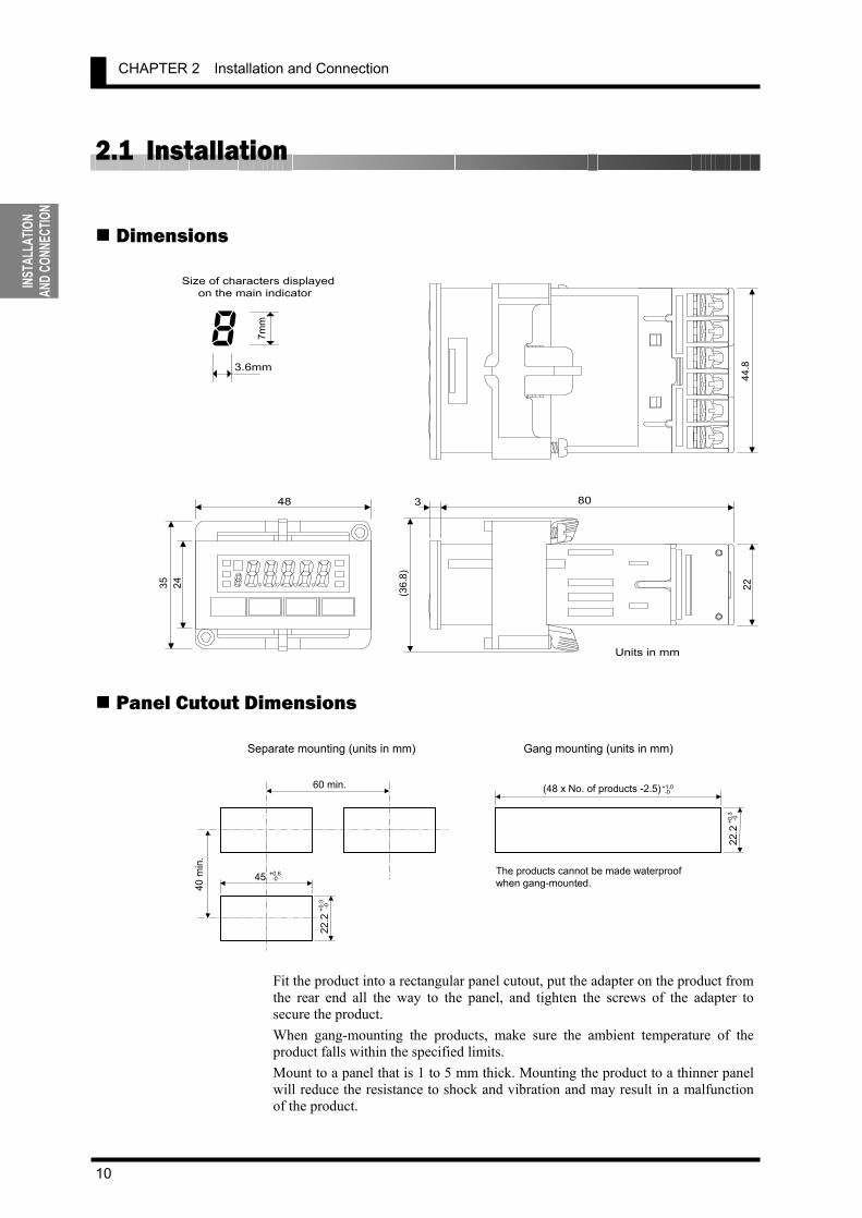
Dimensions
Panel Cutout Dimensions
Fit the product into a rectangular panel cutout, put the adapter on the product from the rear end all the way to the panel, and tighten the screws of the adapter to secure the product. When gang-mounting the products, make sure the ambient temperature of the product falls within the specified limits. Mount to a panel that is 1 to 5 mm thick. Mounting the product to a thinner panel will reduce the resistance to shock and vibration and may result in a malfunction of the product.
3
2435
48
(36.
8)
80
2244
.8
Units in mm
8 7mm
3.6mm
Size of characters displayedon the main indicator
Separate mounting (units in mm) Gang mounting (units in mm)
45 +0.6 -0
22.2
+0.3
-0
40 m
in.
60 min. (48 x No. of products -2.5)+1.0 -0
22.2
+0.3
-0
The products cannot be made waterproofwhen gang-mounted.
2.1 Installation
11
INSTALLATIONANDCONNECTION
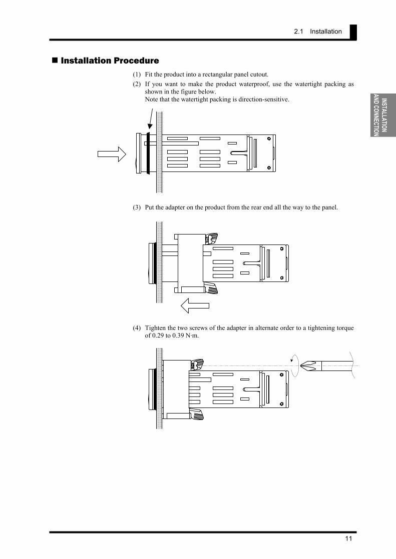
Installation Procedure (1) Fit the product into a rectangular panel cutout. (2) If you want to make the product waterproof, use the watertight packing as
shown in the figure below. Note that the watertight packing is direction-sensitive.
(3) Put the adapter on the product from the rear end all the way to the panel.
(4) Tighten the two screws of the adapter in alternate order to a tightening torque
of 0.29 to 0.39 N·m.

CHAPTER 2 Installation and Connection
12
INSTA
LLAT
ION
AND C
ONNE
CTIO
N
2.2 I/O Terminal Connections Terminal Arrangement
Terminal No. Name Description Applicable model
- Operation power supply Operation power supply terminals All models
- Event input
or pulse contact/
input
Depending on parameter setting: • Hold the process value. • Serve as input terminals for the
forced-zero or forced-zero cancel operation.
• Serve as pulse input terminals when the input type is set to "pulse".
K3GN-ND_-_ 24VDC
- K3GN-PD_-_ 24VDC - Analog input Voltage/current analog terminals All models
Communication RS-485 communication terminals K3GN-_D_-FLK 24VDC Linear current output Linear current output K3GN-___-L1 24VDC - Linear voltage output Linear voltage output K3GN-___-L2 24VDC
11 -12 Provide comparative output. K3GN-_DC-_ 24VDC
11 -12 Comparative output
Provide PASS output in addition to OUT1/OUT2 (comparative output 1/2) when the product is of transistor output type.
K3GN-NDT1-_ 24VDC K3GN-PDT2-_ 24VDC
Terminal Connection Wire the terminals using M3 crimp contacts of the type shown below.
5.8 mm max
5.8 mm max
9 10 11 12OUT1 OUT2 COMPASS
9 10 11 12OUT1 OUT2 COMPASS
1 2 3
NPN input
PNP input
1 2 3
Control voltage 24VDC Event input or
pulse input
4 5 6
Analog input
COMB Analog
input
C
Without communication
function
With communication
function 7 8B (+) A (-)
RS485
7 8NC NC
D
Relay output
NPN tran- sistor output
PNP tran- sistor output
9 10 11 12OUT1 OUT2 COMNC
7 8 9 10 11 12
1 2 3 4 5 6
A
B
C D
Control voltage 24VDC
Event input orpulse input
With linear output 7 8
(+) (-)
Current/Voltage
Voltage Current
A
2.2 I/O Terminal Connections
13
INSTALLATIONANDCONNECTION
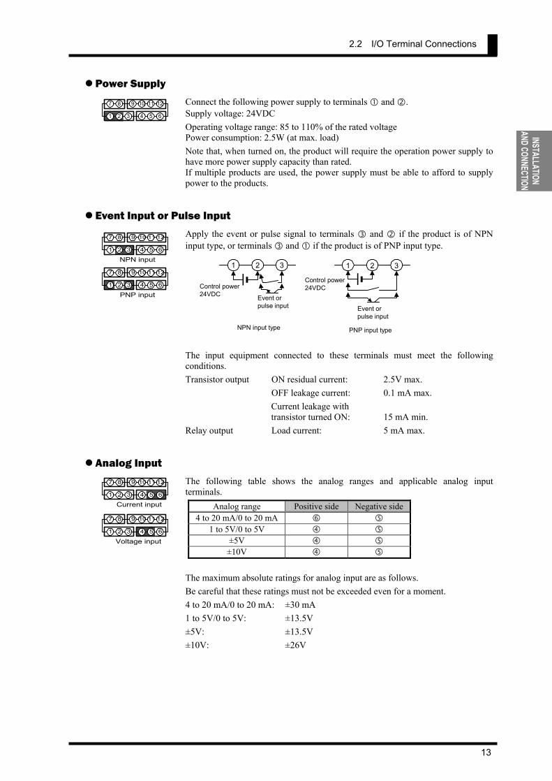
Power Supply Connect the following power supply to terminals and . Supply voltage: 24VDC Operating voltage range: 85 to 110% of the rated voltage Power consumption: 2.5W (at max. load) Note that, when turned on, the product will require the operation power supply to have more power supply capacity than rated. If multiple products are used, the power supply must be able to afford to supply power to the products.
Event Input or Pulse Input Apply the event or pulse signal to terminals and if the product is of NPN input type, or terminals and if the product is of PNP input type.
The input equipment connected to these terminals must meet the following conditions. Transistor output ON residual current: 2.5V max. OFF leakage current: 0.1 mA max. Current leakage with transistor turned ON: 15 mA min. Relay output Load current: 5 mA max.
Analog Input The following table shows the analog ranges and applicable analog input terminals.
Analog range Positive side Negative side4 to 20 mA/0 to 20 mA
1 to 5V/0 to 5V ±5V
±10V The maximum absolute ratings for analog input are as follows. Be careful that these ratings must not be exceeded even for a moment. 4 to 20 mA/0 to 20 mA: ±30 mA 1 to 5V/0 to 5V: ±13.5V ±5V: ±13.5V ±10V: ±26V
7 8 9 10 11 12
1 2 3 4 5 6
7 8 9 10 11 12
1 2 3 4 5 6
7 8 9 10 11 12
1 2 3 4 5 6
NPN input
PNP input
7 8 9 10 11 12
1 2 3 4 5 6
7 8 9 10 11 12
1 2 3 4 5 6
Voltage input
Current input
NPN input type PNP input type
1 2 3
Control power 24VDC
Event or pulse input
1 2 3
Control power 24VDC Event or
pulse input
CHAPTER 2 Installation and Connection
14
INSTA
LLAT
ION
AND C
ONNE
CTIO
N
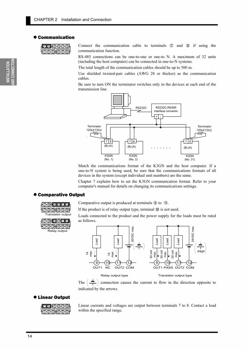
Communication Connect the communication cable to terminals and if using the communication function. RS-485 connections can be one-to-one or one-to N. A maximum of 32 units (including the host computer) can be connected in one-to-N systems. The total length of the communication cables should be up to 500 m. Use shielded twisted-pair cables (AWG 28 or thicker) as the communication cables. Be sure to turn ON the terminator switches only in the devices at each end of the transmission line.
Match the communications format of the K3GN and the host computer. If a one-to-N system is being used, be sure that the communications formats of all devices in the system (except individual unit numbers) are the same. Chapter 7 explains how to set the K3GN communication format. Refer to your computer's manual for details on changing its communications settings.
Comparative Output Comparative output is produced at terminals to 12 . If the product is of relay output type, terminal is not used. Loads connected to the product and the power supply for the loads must be rated as follows.
The connection causes the current to flow in the direction opposite to indicated by the arrows.
Linear Output Linear currents and voltages are output between terminals 7 to 8. Contact a load within the specified range.
7 8 9 10 11 12
1 2 3 4 5 6
7 8 9 10 11 12
1 2 3 4 5 6
Transistor output
7 8 9 10 11 12
1 2 3 4 5 6
Relay output
OUT1 OUT2 COMNC
9 10 11 12
Load
Load
1A max
.
OUT1 OUT2 COMPASS
9 10 11 12
Load
Load
Load
PNP
30VD
C m
ax.
1A max
.
24VD
C m
ax.
50 m
Am
ax.
50 m
Am
ax.
50 m
Am
ax.
Relay output type Transistor output type
7 8(B) (A)
7 8
(B) (A)
7 8
(B) (A)
K3GN(No. 1)
K3GN(No. 2)
K3GN(No. 31)
+ -
RS232C-RS485 interface convertor RS232C
Terminator 120Ω(1/2Ω)
(
Terminator 120Ω(1/2Ω)
(
7 8 9 10 11 12
1 2 3 4 5 6
2.2 I/O Terminal Connections
15
APPLICATION EXAMPLES
3 APPLICATION EXAMPLES
3.1 Monitoring the Remaining Quantity of Soup・・・・・・・・・・・・・・・・・ 16 3.2 Monitoring the Load Current of a Motor ・・・・・・・・・・・・・・・・・・・・ 18 3.3 Monitoring the Quantity of Dust・・・・・・・・・・・・・・・・・・・・・・・・・・・・ 20 3.4 Monitoring the Internal Pressure of a Tank ・・・・・・・・・・・・・・・・・・ 22 3.5 Monitoring the Rotational Speed of a Motor ・・・・・・・・・・・・・・・・・ 24 3.6 Using the Product as a Digital Indicator for PLC ・・・・・・・・・・・・・ 26
This chapter shows some examples of product applications.
CHAPTER
CHAPTER 3 APPLICATION EXAMPLES
16
APPL
ICAT
ION
EXAM
PLES
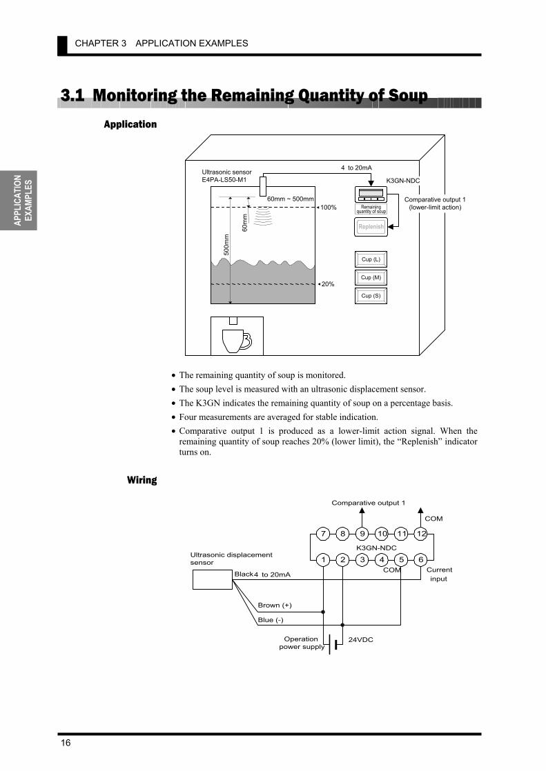
3.1 Monitoring the Remaining Quantity of Soup
• The remaining quantity of soup is monitored. • The soup level is measured with an ultrasonic displacement sensor. • The K3GN indicates the remaining quantity of soup on a percentage basis. • Four measurements are averaged for stable indication. • Comparative output 1 is produced as a lower-limit action signal. When the
remaining quantity of soup reaches 20% (lower limit), the “Replenish” indicator turns on.
Application
Wiring
7 8 9 10 11 12
1 2 3 4 5 6
4 to 20mACurrentinput
COM
Operationpower supply
24VDC
K3GN-NDC
Black
Ultrasonic displacementsensor
Brown (+)
Blue (-)
COM
Comparative output 1
K3GN-NDC
Cup (L)
Remaining quantity of soup
Cup (M)
Cup (S) 20%
100%
Replenish
4 to 20mA
Comparative output 1(lower-limit action)
Ultrasonic sensorE4PA-LS50-M1
500m
m 60
mm
60mm ~ 500mm

3.1 Monitoring the Remaining Quantity of Soup
17
APPLICATION EXAMPLES
Set the parameters of the K3GN as follows.
Level Parameter Set value in-t analg
range 4-20
inp.1 4.00
dsp.1 100
inp.2 20.00
dsp.2 0
dp ,,,,,
Initial setting
out1.t lo
Advanced-function setting avg 4
Operation setting out1 20 Set the analog output characteristic mode of the sensor to “decrease”. For details on sensor setting, refer to the Operation Manual for the sensor.
• Comparative output 1 turns on when the remaining quantity of soup decreases to
20%.
Parameter Setting
OperationRemaining quantity
of soup
OUT1 lowerlimit value
(20)
Comparativeoutput 1

CHAPTER 3 APPLICATION EXAMPLES
18
APPL
ICAT
ION
EXAM
PLES
3.2 Monitoring the Load Current of a Motor
• The load current of a motor is monitored. • A 10:1 current transformer is used to detect the motor current. • The current transformer K3FK-CE-1A-R is used to adapt the input current to a
K3GN analog range. • The K3GN indicates the load current in units of amperage to two decimal places. • Comparative output 1 is used to generate an upper-limit action signal and
comparative output 2 is used to generate a lower-limit action signal. • The OUT upper-limit value is set to 6.00A and the OUT lower-limit value is set
to 3.00A.
Application
Wiring
7 8 9 10 11 12
1 2 3 4 5 6
7
8
1
2
Line side
Load side
K
L
l
k3
4
Current protectorK3FK-CTM
K3FK-CE-1A-R
Signal output
+
-
Current input
COM
Operation power supply
24VDC
+
-
K3GN-NDC
COM
Comparativeoutput 1
Comparativeoutput 2
Power supply
Signal input Electro-
magnetic relay
24VDC power supply
Comparative output 1
(upper-limit action)
Comparative output 2
(lower-limit action)Current transformer K3FK-CE-1A-R
0 to 10A AC 10:1 current transformer
0 to 1A 4 to 20mA K3GN-NDC
K3GN
/ZERO
ZERO HOLD OUT1
( ( 8 ( 8( CMW OUT2SV

3.2 Monitoring the Load Current of a Motor
19
APPLICATION EXAMPLES
Set the parameters of the K3GN as follows. Level Parameter Set value
in-t analg
range 4-20
inp.1 4.00
dsp.1 0
inp.2 20.00
dsp.2 1000
dp ,,,.,,
out1.t hi
Initial setting
out2.t lo
out1 6.00 Operation settingout2 3.00
For details on the parameters, refer to CHAPTER 5 OPERATION.
• Turning the power on causes inrush current to flow through the motor. But the
K3GN does not produce superfluous output in response to the inrush current because it does not perform measuring operation for approx. one second after turn-on.
• Comparative output 1 turns on when the current flowing through the motor reaches 6.00A. Comparative output 2 turns on when the current flowing through the motor decreases to 3.00A.
Parameter Setting
Operation
Signal input
Load current
OUT1 value(Upper limit: 6.00)
OUT2 value(Lower limit: 3.00)
Measurement
Indication Current value indication
Approx.1 sec.
Comparativeoutput 1
Comparativeoutput 2

CHAPTER 3 APPLICATION EXAMPLES
20
APPL
ICAT
ION
EXAM
PLES
3.3 Monitoring the Quantity of Dust
• The quantity of dust exhausted from a dust collector into the air is monitored. • The analog photoelectric sensor E3SA is used to detect the quantity of dust. • A dust quantity of 0 to 1500 ppm corresponds to an E3SA output of 4 to 20 mA. • The K3GN indicates the quantity of dust in units of ppm. • Comparative output 1 is used to generate an upper-limit action signal that
reduces the crusher power. • Comparative output 2 is used to generate another upper-limit action signal that
stops the crusher. • The OUT 1 upper-limit value is 800 ppm and the OUT2 upper-limit value is
1000 ppm. • Eight measurements are averaged for stable indication. • The hysteresis is set to 10 for stable output in the vicinity of the OUT set values.
Application
Wiring
To the air
Dust collector
Crusher
0 to 1500ppm
K3GN-NDC
4 to 20mA
Analog photoelectric sensor E3SA
Comparative output 1 (upper-limit action) Crusher powerreduction command
Comparative output 2(upper-limit action)Crusher stop command
K3GN
/ZERO
ZERO HOLD OUT1
( ( 8 ( 8( CMW OUT2SV
7 8 9 10 11 12
1 2 3 4 5 6
4 to 20mA Currentinput
COM
Operationpower supply 24VDC
K3GN-NDC
COM
Comparative output 1
Comparativeoutput 2
Stripes of orange/purple
Brown (+)
Blue (-)
Black
Analog photoelectricsensor E3SA
3.3 Monitoring the Quantity of Dust
21
APPLICATION EXAMPLES
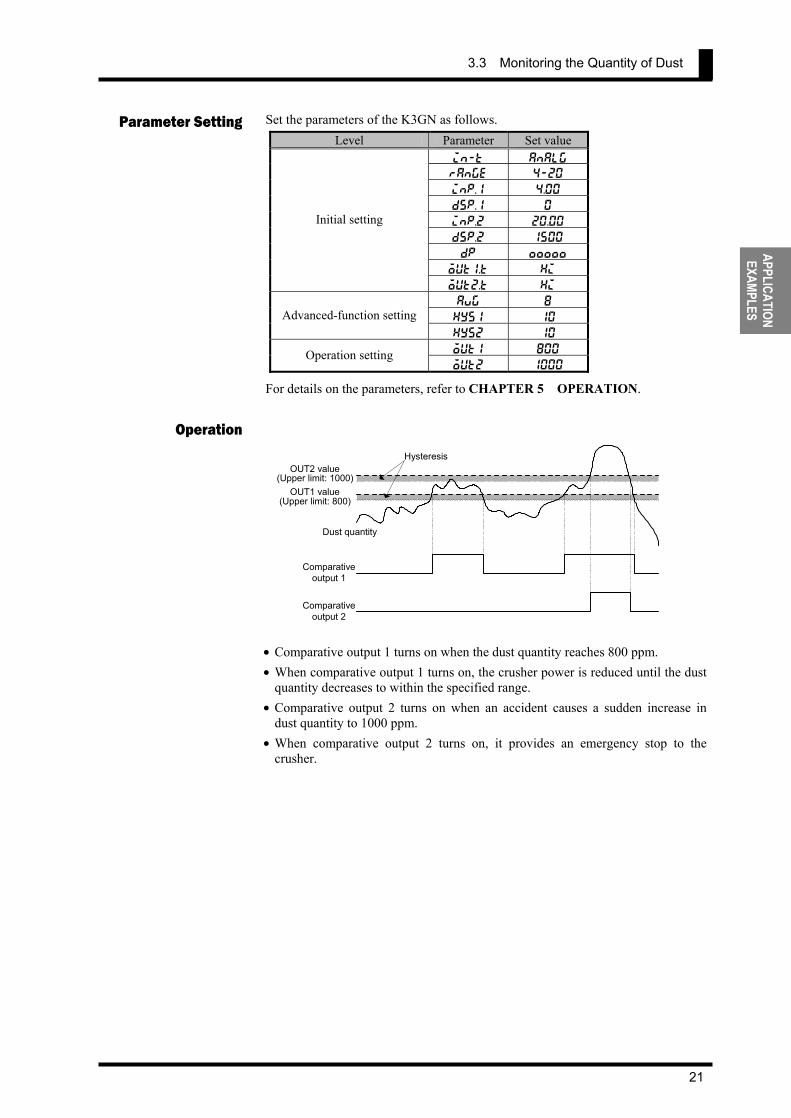
Set the parameters of the K3GN as follows. Level Parameter Set value
in-t analg
range 4-20
inp.1 4.00
dsp.1 0
inp.2 20.00
dsp.2 1500
dp ,,,,,
out1.t hi
Initial setting
out2.t hi
avg 8
hys1 10 Advanced-function settinghys2 10
out1 800 Operation setting out2 1000
For details on the parameters, refer to CHAPTER 5 OPERATION.
• Comparative output 1 turns on when the dust quantity reaches 800 ppm. • When comparative output 1 turns on, the crusher power is reduced until the dust
quantity decreases to within the specified range. • Comparative output 2 turns on when an accident causes a sudden increase in
dust quantity to 1000 ppm. • When comparative output 2 turns on, it provides an emergency stop to the
crusher.
Parameter Setting
Operation
Dust quantity
OUT1 value(Upper limit: 800)
OUT2 value(Upper limit: 1000)
Comparativeoutput 1
Comparativeoutput 2
Hysteresis

CHAPTER 3 APPLICATION EXAMPLES
22
APPL
ICAT
ION
EXAM
PLES
3.4 Monitoring the Internal Pressure of a Tank
• The internal pressure of a tank is monitored. • The pressure sensor E8AA-M10 is used to detect the pressure in the tank. • A pressure of 0 to 980 kPa corresponds to an E8AA-M10 output of 4 to 20 mA. • The K3GN indicates the pressure in units of kPa to one decimal place. • The communication function of the K3GN enables remote monitoring of the
pressure on the host PC. • The status of comparative outputs is read by the host PC at a remote site. • Comparative output 1 turns on when the pressure reaches 550.0 kPa, which
generates an upper-limit action signal. • Comparative output 2 turns on when the pressure decreases to 100.0 kPa, which
generates a lower-limit action signal.
Application
Wiring
7 8 9 10 11 12
1 2 3 4 5 6
4 to 20mA Currentinput
COM
Operationpower supply 24VDC
K3GN-NDC-FLK
Black
Pressure sensorE8AA-M10
Brown (+)
Blue (-)
B(+) A(-)
To host PCvia RS-485
K3GN-NDC-FLK
4 to 20mA
Pressure sensor E8AA-M10
Tank
0 to 980kPa
Host PC
RS485 RS232C
K3GN
/ZERO
ZEROHOLD
OUT1 ( (8T
( 8 ( CMWOUT2
SV

3.4 Monitoring the Internal Pressure of a Tank
23
APPLICATION EXAMPLES
Set the parameters of the K3GN as follows. Level Parameter Set value
in-t analg
range 4-20
inp.1 4.00
dsp.1 0
inp.2 20.00
dsp.2 9800
dp ,,,,.,
out1.t hi
Initial setting
out2.t lo
u-no 1
bps 9.6 len 7
sbit 2
Communication setting
prty even
out1 550.0 Operation settingout2 100.0
Set the communication parameters according to the host PC setting. For details on the parameters, refer to CHAPTER 5 OPERATION.
• The host PC reads the current value and the status from the K3GN at regular
intervals. Of command and response frames, only text fields are shown in the above figure. For details on communications, refer to CHAPTER 7 COMMUNICATIONS.
Parameter Setting
Operation
Tank pressure
OUT1 value(Upper limit: 550.0)
OUT2 value(Lower limit: 100.0)
Command 1
534.2kPa
568.8kPa
Response 1
Command 2
Response 2
"000014DE"
MRC
"01"
SRC
"01"
Variabletype
"C0" "0001"
Address Bit position
"00" "0002" No. of elements
MRC
"01"
SRC
"01" "0000"
Response code Current value Command 1
Response 1 "00000400"
Status
14DEH (5342 in decimal) (PASS output ON)
"00001638"
MRC
"01"
SRC
"01"
Variabletype
"C0" "0001"
Address Bit position
"00" "0002" No. of elements
MRC
"01"
SRC
"01" "0000"
Response code Current value Command 2
Response 2 "00000100"
Status
1638H (5688 in decimal) (Comparative output 1 ON)

CHAPTER 3 APPLICATION EXAMPLES
24
APPL
ICAT
ION
EXAM
PLES
3.5 Monitoring the Rotational Speed of a Motor
• In addition to the load current monitored in the application shown in Section 3.2, the rotational speed of a motor is also monitored with an additional K3GN.
• A four-toothed wheel is installed on the motor shaft to allow detection of its rotational speed.
• The proximity sensor E2E-X1R5E1 converts motor shaft rotations to on/off pulses.
• The K3GN indicates the rotational speed in terms of rpm. • A startup compensation timer is used to prevent superfluous output from being
produced until the motor reaches a designated speed (for five seconds after startup).
• Comparative output 1 is used to generate an upper-limit action signal. Comparative output 2 is used to generate a lower-limit action signal.
• The OUT1 upper-limit value is set to 3500 rpm and the OUT2 lower-limit value to 1000 rpm.
• The auto-zero function is used to enhance the lower-limit response. (A speed of 150 rpm or less is automatically shifted to zero).
Application
Wiring
7 8 9 10 11 12
1 2 3 4 5 6
Proximity sensorE2E-X1R5E1
Pulse input
Operationpower supply 24VDC
Brown (+)
K3GN-NDC
COM
Comparative output 1
Comparativeoutput 2
Blue (-)
Black
Power supply Signal input
Electro-magnetic
relay
24VDC power supply
Comparative output 1
(upper-limit action)
Comparative output 2
(lower-limit action) Current transformer K3FK-CE-1A-R K3GN-NDC
0 to 10A AC Currenttransformer 10:1
0 to 1A 4 to 20mA
Proximity sensor E2E-X1R5E1
Comparative output 1
(upper-limit action)
Comparative output 2
(lower-limit action) K3GN-NDC
K3GN
/ZERO
ZERO HOLD OUT1
( ( 8 T
( 8( CMW OUT2SV
K3GN
/ZERO
ZERO HOLD OUT1
( ( 8 T
( 8( CMW OUT2SV

3.5 Monitoring the Rotational Speed of a Motor
25
APPLICATION EXAMPLES
Set the parameters of the K3GN as follows.
Level Parameter Set value in-t pulse p-fre 5k
inp 1000
dsp 15000
dp ,,,,,
out1.t hi
Initial setting
out2.t lo
auto.z 0.1 Advanced-function settings-tmr 5.0
out1 3500 Operation setting out2 1000
For details on the parameters, refer to CHAPTER 5 OPERATION.
• The startup compensation timer works for five seconds after the motor power is
turned on. This prevents superfluous output from being produced by the K3GN.
• Comparative output 1 turns on when the motor speed reaches 3500 rpm. Comparative output 2 turns on when the motor speed decreases to 1000 rpm.
Parameter Setting
Operation
Signal input
Motor speed
OUT1 value(Upper limit: 3500)
OUT 2 value(Lower limit: 1000)
Measurement
Indication Current value indication
5 sec.
Comparativeoutput 1
Comparativeoutput 2
CHAPTER 3 APPLICATION EXAMPLES
26
APPL
ICAT
ION
EXAM
PLES
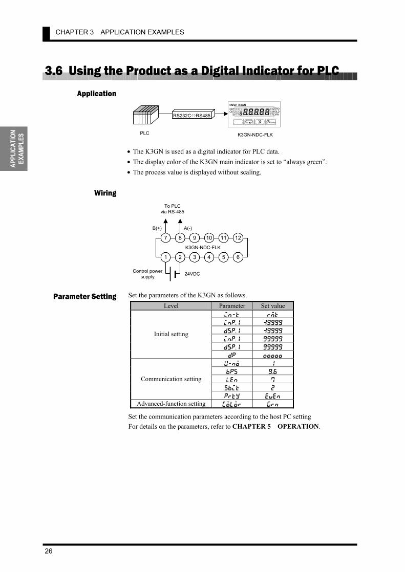
3.6 Using the Product as a Digital Indicator for PLC
• The K3GN is used as a digital indicator for PLC data. • The display color of the K3GN main indicator is set to “always green”. • The process value is displayed without scaling.
Set the parameters of the K3GN as follows.
Level Parameter Set value in-t rmt inp.1 :9999
dsp.1 :9999
inp.1 99999
dsp.1 99999
Initial setting
dp ,,,,,
u-no 1
bps 9.6 len 7
sbit 2
Communication setting
prty even
Advanced-function setting color grn Set the communication parameters according to the host PC setting For details on the parameters, refer to CHAPTER 5 OPERATION.
Application
Wiring
Parameter Setting
7 8 9 10 11 12
1 2 3 4 5 6
Control powersupply 24VDC
K3GN-NDC-FLK
B(+) A(-)
To PLCvia RS-485
K3GN-NDC-FLK
RS232C RS485
PLC
K3GN
/ZERO
ZERO HOLD OUT1
( ( 8 T
( 8( CMW OUT2SV
3.6 Using the Product as a Digital Indicator for PLC
27
APPLICATION EXAMPLES
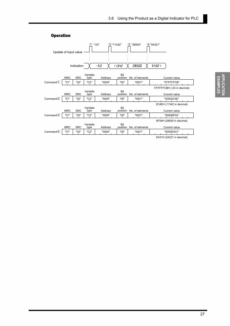
Operation
Update of input value
Indication
MRC
"01"
SRC
"02" "C2" "0000"
Address
"00" "0001" No. of elements
-53
"-53" "11342" "28500" "54321"
11342 28500 54321
"FFFFFFCB"Current value
FFFFFFCBH (-53 in decimal)
Command
MRC
"01"
SRC
"02" "C2" "0000"
Address
"00" "0001" No. of elements
"00002C4E"Current value
2C4EH (11342 in decimal)
MRC
"01"
SRC
"02" "C2" "0000"
Address
"00" "0001" No. of elements
"00006F54"Current value
MRC
"01"
SRC
"02" "C2" "0000"
AddressBit
position
"00" "0001" No. of elements
"0000D431"Current value
6F54H (28500 in decimal)
D431H (54321 in decimal)
Command
Command
Command
Variabletype
Bitposition
Variabletype
Bitposition
Variabletype
Bitposition
Variabletype
1 2 3 4
1
2
3
4

3.6 Using the Product as a Digital Indicator for PLC
29
INITIAL SETTING
4 INITIAL SETTING
4.1 Using the Product as a process meter・・・・・・・・・・・・・・・・・・・・・・・・ 30 4.2 Using the Product as a Tachometer ・・・・・・・・・・・・・・・・・・・・・・・・・ 32 4.3 Using the Product as a Digital Indicator ・・・・・・・・・・・・・・・・・・・・・ 34
Typical applications of the product include a process meter, a tachometer, or an indicator of digital data from PLC/PC. This chapter explains the flow of initial setting for each of these applications.
CHAPTER
CHAPTER 4 INITIAL SETTING
30
INIT
IAL
SETT
ING
4.1 Using the Product as a process meter The following example shows the flow of initial setting for the product that is used as a process meter.
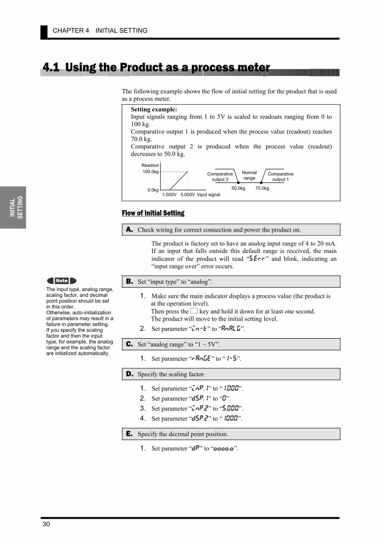
Setting example: Input signals ranging from 1 to 5V is scaled to readouts ranging from 0 to 100 kg. Comparative output 1 is produced when the process value (readout) reaches 70.0 kg. Comparative output 2 is produced when the process value (readout) decreases to 50.0 kg.
Flow of Initial Setting
A. Check wiring for correct connection and power the product on.
The product is factory set to have an analog input range of 4 to 20 mA. If an input that falls outside this default range is received, the main indicator of the product will read “s.err” and blink, indicating an “input range over” error occurs.
B. Set “input type” to “analog”.
1. Make sure the main indicator displays a process value (the product is at the operation level). Then press the L key and hold it down for at least one second. The product will move to the initial setting level.
2. Set parameter “in-t” to “analg”.
C. Set “analog range” to “1 ~ 5V”.
1. Set parameter “range” to “1-5”.
D. Specify the scaling factor.
1. Set parameter “inp.1” to “1.000”. 2. Set parameter “dsp.1” to “0”. 3. Set parameter “inp.2” to “5.000”. 4. Set parameter “dsp.2” to “1000”.
E. Specify the decimal point position.
1. Set parameter “dp” to “,,,,.,”.
The input type, analog range, scaling factor, and decimal point position should be set in this order. Otherwise, auto-initialization of parameters may result in a failure in parameter setting. If you specify the scaling factor and then the input type, for example, the analog range and the scaling factor are initialized automatically.
Note
Input signal1.000V 5.000V
100.0kg
0.0kg
ReadoutNormal range Comparative
output 2Comparative
output 1
50.0kg 70.0kg
4.1 Using the Product as a process meter
31
INITIAL SETTING
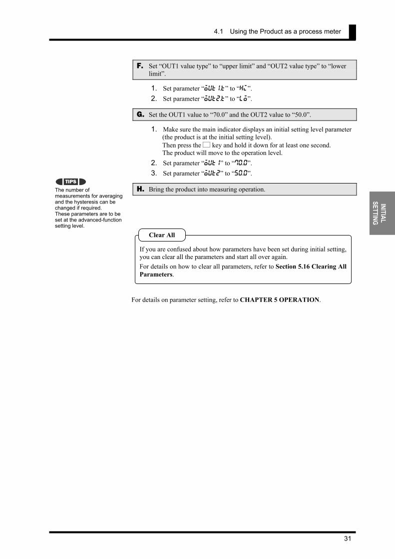
F. Set “OUT1 value type” to “upper limit” and “OUT2 value type” to “lower limit”.
1. Set parameter “out1.t” to “hi”. 2. Set parameter “out2.t” to “lo”.
G. Set the OUT1 value to “70.0” and the OUT2 value to “50.0”.
1. Make sure the main indicator displays an initial setting level parameter (the product is at the initial setting level). Then press the L key and hold it down for at least one second. The product will move to the operation level.
2. Set parameter “out1” to “70.0”. 3. Set parameter “out2” to “50.0”.
H. Bring the product into measuring operation.
For details on parameter setting, refer to CHAPTER 5 OPERATION.
The number of measurements for averaging and the hysteresis can be changed if required. These parameters are to be set at the advanced-function setting level.
If you are confused about how parameters have been set during initial setting,you can clear all the parameters and start all over again. For details on how to clear all parameters, refer to Section 5.16 Clearing AllParameters.
Clear All
TIPS

CHAPTER 4 INITIAL SETTING
32
INIT
IAL
SETT
ING
4.2 Using the Product as a Tachometer The following example shows the flow of initial setting for the product that is used as a tachometer.
Setting example: The speed of a conveyor belt is indicated in terms of m/min. Four pulses are generated per rotation of the rotor. The diameter of the rotor is 12 cm. Comparative output 1 is produced when the speed reaches 10500 m/min. Comparative output 2 is produced when the speed decreases to 9500 m/min.
How to Determine the Scaling Factor Determine the scaling factor as follows.
Rotor rotational speed (rpm) = Input frequency (Hz)/Number of pulses per rotation × 60
Belt Speed (m/min) = π × Rotor diameter (m) × Rotor rotational speed (rpm)
Hence the belt speed is given as
Belt speed (m/min) = 3.14159… × 0.12 × 60/4 × Input frequency (Hz) = 5.654866… × Input frequency (Hz)
Multiply the result by 1000 to enable a readout to be displayed to three decimal places.
Belt speed (m/min) = 5654.866… × Input frequency (Hz)
To minimize the scaling operation error, select such an input frequency that allows readouts to contain the largest possible number of digits. In this example, the input frequency is set to 10 Hz so that the readout is 56549.
Flow of Initial Setting
A. Check wiring for correct connection and power the product on.
The product is factory set to have an analog input range of 4 to 20 mA. If an input that falls outside this default range is received, the main indicator of the product will read “s.err” and blink, indicating an “input range over” error occurs.
The input type, pulse frequency, scaling factor, and decimal point position should be set in this order. Otherwise, auto-initialization of parameters may result in a failure in parameter setting. If you specify the scaling factor and then the input type, for example, the pulse frequency and the scaling factor are initialized automatically.
Note
m/min
12cm9.500 m/min
10.500m/min
Normal range Comparative
output 2 Comparative
output 1
Inputsignal
10Hz
Readout56549
4.2 Using the Product as a Tachometer
33
INITIAL SETTING
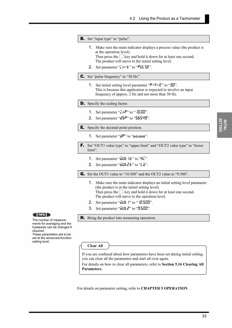
B. Set “input type” to “pulse”.
1. Make sure the main indicator displays a process value (the product is at the operation level). Then press the L key and hold it down for at least one second. The product will move to the initial setting level.
2. Set parameter “in-t” to “pulse”.
C. Set “pulse frequency” to “30 Hz”.
1. Set initial setting level parameter “p-fre” to “30”. This is because this application is expected to involve an input frequency of approx. 2 Hz and not more than 30 Hz.
D. Specify the scaling factor.
1. Set parameter “inp” to “10.00”. 2. Set parameter “dsp” to “56549”.
E. Specify the decimal point position.
1. Set parameter “dp” to “,,.,,,”.
F. Set “OUT1 value type” to “upper limit” and “OUT2 value type” to “lower limit”.
1. Set parameter “out1.t” to “hi”. 2. Set parameter “out2.t” to “lo”.
G. Set the OUT1 value to “10.500” and the OUT2 value to “9.500”.
1. Make sure the main indicator displays an initial setting level parameter (the product is at the initial setting level). Then press the L key and hold it down for at least one second. The product will move to the operation level.
2. Set parameter “out1” to “10.500”. 3. Set parameter “out2” to “9.500”.
H. Bring the product into measuring operation.
For details on parameter setting, refer to CHAPTER 5 OPERATION.
The number of measure-ments for averaging and the hysteresis can be changed if required. These parameters are to be set at the advanced-function setting level.
If you are confused about how parameters have been set during initial setting,you can clear all the parameters and start all over again. For details on how to clear all parameters, refer to Section 5.16 Clearing AllParameters.
Clear All
TIPS

CHAPTER 4 INITIAL SETTING
34
INIT
IAL
SETT
ING
4.3 Using the Product as a Digital Indicator for PLC Data The following example shows the flow of initial setting for the product that is used as a digital indicator for PLC data.
Setting example: Full span 0H to 0FA0H (0 to 4000 in decimal) of a PLC analog input unit is scaled to 80.0 to 120.0 mm and displayed. Comparative output 1 is produced when the process value reaches 110.0 mm. Comparative output 2 is produced when the process value decreases to 90.0 mm.
Flow of Initial Setting
A. Check wiring for correct connection and power the product on.
The product is factory set to have an analog input range of 4 to 20 mA. If an input that falls outside this default range is received, the main indicator of the product will read “s.err” and blink, indicating an “input range over” error occurs..
B. Set “input type” to “remote”.
1. Make sure the main indicator displays a process value (the product is at the operation level). Then press the L key and hold it down for at least one second. The product will move to the initial setting level.
2. Set parameter “in-t” to “rmt”.
C. Specify the scaling factor.
1. Set parameter “inp.1” to “0”. 2. Set parameter “dsp.1” to “800”. 3. Set parameter “inp.2” to “4000”. 4. Set parameter “dsp.2” to “1200”.
D. Specify the decimal point position.
1. Set parameter “dp” to “,,,,.,”.
E. Set “OUT1 value type” to “upper limit” and “OUT2 value type” to “lower limit”.
1. Set parameter “out1.t” to “hi”. 2. Set parameter “out2.t” to “lo”.
Setting “input type” to “remote” sets the adjustment level parameter “downloading (communication writing)” to “enable” automatically. The "CMW" indicator on the front panel will be illuminated.
The input type, scaling factor, and decimal point position should be set in this order. Otherwise, auto-initialization of parameters may result in a failure in parameter setting. If you specify the scaling factor and then the input type, for example, the scaling factor is initialized automatically.
Note
TIPS
Input signal0 4000
120.0mm
80.0mm
Readout
90.0mm 110.0mm
Normal range Comparative
output 2Comparative
output 1
4.3 Using the Product as a Digital Indicator for PLC Data
35
INITIAL SETTING
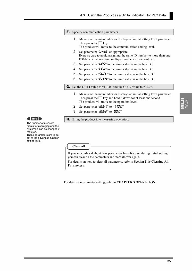
F. Specify communication parameters.
1. Make sure the main indicator displays an initial setting level parameter. Then press the L key. The product will move to the communication setting level.
2. Set parameter “u-no” as appropriate. Exercise care to avoid assigning the same ID number to more than one K3GN when connecting multiple products to one host PC.
3. Set parameter “bps” to the same value as in the host PC. 4. Set parameter “len” to the same value as in the host PC. 5. Set parameter “sbit” to the same value as in the host PC. 6. Set parameter “prty” to the same value as in the host PC.
G. Set the OUT1 value to “110.0” and the OUT2 value to “90.0”.
1. Make sure the main indicator displays an initial setting level parameter. Then press the L key and hold it down for at least one second. The product will move to the operation level.
2. Set parameter “out1” to “110.0”. 3. Set parameter “out2” to “90.0”.
H. Bring the product into measuring operation.
For details on parameter setting, refer to CHAPTER 5 OPERATION.
The number of measure-ments for averaging and the hysteresis can be changed if required. These parameters are to be set at the advanced-function setting level.
If you are confused about how parameters have been set during initial setting,you can clear all the parameters and start all over again. For details on how to clear all parameters, refer to Section 5.16 Clearing AllParameters.
Clear All
TIPS

4.3 Using the Product as a Digital Indicator for PLC Data
37
OPERATION
5 OPERATION
5.1 Levels ・・・・・・・・・・・・・・・・・・・・・・・・・・・・・・・・・・・・・・・・・・・・・・・・・・・ 38 5.2 Moving among Levels・・・・・・・・・・・・・・・・・・・・・・・・・・・・・・・・・・・・・ 40 5.3 Parameters ・・・・・・・・・・・・・・・・・・・・・・・・・・・・・・・・・・・・・・・・・・・・・・・ 42 5.4 Set Values ・・・・・・・・・・・・・・・・・・・・・・・・・・・・・・・・・・・・・・・・・・・・・・・ 44 5.5 Operation Level ・・・・・・・・・・・・・・・・・・・・・・・・・・・・・・・・・・・・・・・・・・ 45
Viewing and Changing /Forced-zero operation 5.6 Communication Writing Control ・・・・・・・・・・・・・・・・・・・・・・・・・・・ 47 5.7 Key Protect Setting ・・・・・・・・・・・・・・・・・・・・・・・・・・・・・・・・・・・・・・・ 48 5.8 Selecting an Input Type (in-t)・・・・・・・・・・・・・・・・・・・・・・・・・・・・ 50 5.9 Selecting an Analog Range (range) ・・・・・・・・・・・・・・・・・・・・・・・ 51 5.10 Selecting an Input-pulse Frequency Range (p-fre) ・・・・・・・・・ 52 5.11 Specifying the Scaling Factor for Analog Input/
Digital Data Display (inp.∗, dsp.∗) ・・・・・・・・・・・・・・・・・・・・・・・・ 53 5.12 Specifying the Scaling Factor
for Input Pulse Frequency (inp, dsp) ・・・・・・・・・・・・・・・・・・・・・・ 55 5.13 Specifying the Decimal Point Position (dp) ・・・・・・・・・・・・・・・・・ 58 5.14 Selecting the Output Operating Action (out1.t, out2.t) ・・・・ 59 5.15 Performing Linear Output ・・・・・・・・・・・・・・・・・・・・・・・・・・・・・・・・・ 60 5.16 Specifying Communication Parameters ・・・・・・・・・・・・・・・・・・・・・ 63 5.17 Clearing All Parameters (init)・・・・・・・・・・・・・・・・・・・・・・・・・・・・ 65 5.18 Specifying the Number of Measurements
for Averaging (avg) ・・・・・・・・・・・・・・・・・・・・・・・・・・・・・・・・・・・・・・ 66 5.19 Specifying the Function of the Event Input (event) ・・・・・・・・・ 67 5.20 Specifying the Hysteresis (hys1, hys2)・・・・・・・・・・・・・・・・・・・・ 69 5.21 Specifying the Auto-zero Time (auto.z) ・・・・・・・・・・・・・・・・・・・ 71 5.22 Specifying the Startup Compensation Time (s-tmr)・・・・・・・・・ 73 5.23 Changing the Display Color (color)・・・・・・・・・・・・・・・・・・・・・・・ 75 5.24 Changing the Display Auto-return Time (ret) ・・・・・・・・・・・・・ 77 5.25 Changing the Move-to-Protect-Level Time (prlt) ・・・・・・・・・・ 79 5.26 Changing the Send Waiting Time (sdwt) ・・・・・・・・・・・・・・・・・・・ 81
This chapter describes how to move among levels, changeparameters, and operate the product from the front panel.
CHAPTER

CHAPTER 5 OPERATION
38
OPER
ATIO
N
5.1 Levels In this manual, setting items of the product are grouped into seven levels as follows.
Level Description Measurement
Protect
This level allows parameter setting for protection against unauthorized or inadvertent key operation. Access to protected levels or setting items is disabled.
Yes
Operation
This level represents the normal operation state in which the product can accept input signals and provide comparative outputs. Not only readout of the current process value but also access to or changes of OUT set values are allowed at this level. The product enters this level at power-on.
Yes
Adjustment
This level permits communication writing to be enabled or disabled. Even if communication writing is disabled, reading is always enabled. If your product has no communication function, this level is not available.
Yes
Initial setting
This level allows initial setting of the input type, analog range, scaling factor and the like. Available only for the product with communication function.
No
Communication setting
This level allows setting of the baud rate, word length and other communication parameters. Available only for the product with communication function
No
Advanced-function setting
This level allows setting of the number of measurements for averaging. Customizations such as a change in display color are also possible at this level.
No
Calibration
This level allows user calibration. Note that user calibration could cause deterioration in measuring accuracy of the product.
No
During operation of the product, the level indicator designates the current level. Alphabetic characters shown on the level indicator and their corresponding levels are shown below.
Alphabetic character Level p Protect level
(OFF) Operation level a Adjustment level s Initial Setting level c Communication level f Advanced-Function level u User calibration level
88888p
5.2 Moving among Levels
39
OPERATION
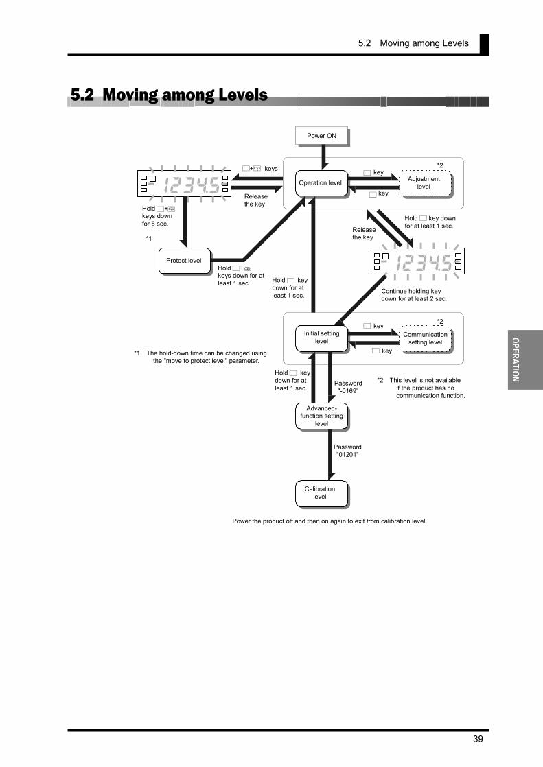
5.2 Moving among Levels
Operation level Adjustment level
Initial setting level
Communication setting level
Advanced- function setting
level
Calibration level
Protect level
L key
L key
1 2 3 $ 5 8
Hold L key downfor at least 1 sec.Release
the key
Continue holding key down for at least 2 sec.
Password "-0169"
Hold L keydown for atleast 1 sec.
1 2 3 $ 5 8
L+M keys
Release the key
Hold L+Mkeys downfor 5 sec.
Hold L+Mkeys down for atleast 1 sec.
*1
*1 The hold-down time can be changed using the "move to protect level" parameter.
Power the product off and then on again to exit from calibration level.
Power ON
*2
*2
*2 This level is not available if the product has no communication function.
Hold L keydown for atleast 1 sec.
Password "01201"
L key
L key
CHAPTER 5 OPERATION
40
OPER
ATIO
N
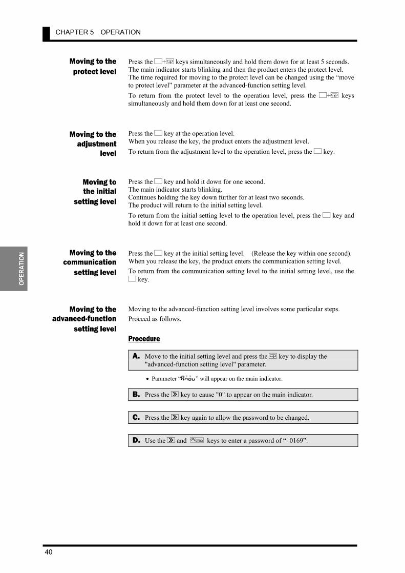
Press the L+M keys simultaneously and hold them down for at least 5 seconds. The main indicator starts blinking and then the product enters the protect level. The time required for moving to the protect level can be changed using the “move to protect level” parameter at the advanced-function setting level. To return from the protect level to the operation level, press the L+M keys simultaneously and hold them down for at least one second. Press the L key at the operation level. When you release the key, the product enters the adjustment level. To return from the adjustment level to the operation level, press the L key. Press the L key and hold it down for one second. The main indicator starts blinking. Continues holding the key down further for at least two seconds. The product will return to the initial setting level. To return from the initial setting level to the operation level, press the L key and hold it down for at least one second. Press the L key at the initial setting level. (Release the key within one second). When you release the key, the product enters the communication setting level. To return from the communication setting level to the initial setting level, use the L key. Moving to the advanced-function setting level involves some particular steps. Proceed as follows.
Procedure
A. Move to the initial setting level and press the M key to display the "advanced-function setting level" parameter.
• Parameter “amov” will appear on the main indicator.
B. Press the S key to cause "0" to appear on the main indicator.
C. Press the S key again to allow the password to be changed.
D. Use the S and ZERO/ keys to enter a password of “–0169”.
Moving to the protect level
Moving to theadjustment
level
Moving tothe initial
setting level
Moving to thecommunication
setting level
Moving to theadvanced-function
setting level

5.2 Moving among Levels
41
OPERATION
E. Press the M key to save the password.
• If the password is correct, the product enters the advanced-function setting level. • If the password is incorrect, the product remains at the initial setting level and its
main indicator displays the next initial setting parameter.
amovs
T
0 s
T
- 0169s T
initf
T
S S
M M M Use S and ZERO/ keys to enter the specified password.
Correct password entered
Incorrect password entered
Next parameter at theinitial setting level
Advanced - function setting level

CHAPTER 5 OPERATION
42
OPER
ATIO
N
5.3 Parameters Setting items at each level are called “parameters”. Use the M key to select a parameter. If the input range is changed, some parameters are set to default values. Therefore, set the input range first.
L L
Press L+ M keys and holddown for at least 5 sec.
oapt
icpt
wtpt
zrpt
Operation/adjustment lockouts
Initial setting/communication lockouts
Setting change lockout
Forced-zero lockout
123$5
out1 Current value
OUT1 upper-limit value
OUT2 upper-limit value
OUT1 value out!h
out!l
out2
outBh
outBl
OUT1 lower-limit value
OUT2 value
OUT2 upper-limit value
cmwt Communications writing control
M
M
Protect level
Operation level
Adjustment level
Press L+ M keys and holddown for at least 1 sec.
Press L key and hold down for at least 1 sec.
*1
*2
*2
*3
*4
*4
*5
M
M
M
M
M
M
M
M
M
Power-on
*8
Press L key and hold down for at least 3 sec.
in-t
Initial setting level
M Input type range
Input-pulse frequency range
Scaling display value 2
Analog range p-fre
inp.1
dsp.1
inp.2
dsp.2
Scaling input value 1
Scaling display value 1
Scaling input value 2
inp
dsp
dp
Scaling input value
Scaling display value
Decimal point position out!t
OUT1 type outBt
OUT2 type
amov
Move to advanced-function level
*6
*7
*8
*8
*8
*8
*7
*7
*9
M
M
M
M
M
M
M
M
M
M
M
M
Linear current output type
Linear voltage output type
Max. value of Linear output
Min. value of Linear output
lset.c
lset.v
lset.h
lset.l
*1 Displayed when parameter "OUT1 type" is set to "upper or lower limit". *2 Displayed when parameter "OUT1 type" is set to "upper and lower limits. *3 Displayed when parameter "OUT2 type" is set to "upper or lower limit". *4 Displayed when parameter "OUT2 type" is set to "upper and lower limits. *5 Accessible when the product has the communication function. *6 Displayed when parameter "input type" is set to "analog". *7 Displayed when parameter "input type" is set to "pulse". *8 Displayed when parameter "input type" is set to "analog" or "remote". *9 Displayed when parameter "initial setting/communication lockouts" is set to "0".
L
M
M
M
M
cn-t
*10 Displayed for models with linear current output. *11 Displayed for models with linear voltage output.
*10
*11
*10
*10
*11
*11
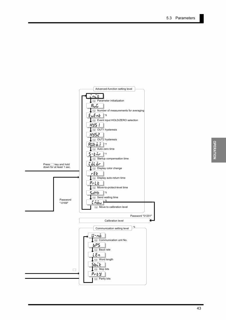
5.3 Parameters
43
OPERATION
init
Advanced-function setting level
L
Communication setting level *5
u-no
bps
Communication unit No.
Word length
Baud rate len
sbit
prty
Stop bits
Parity bits
M
M
M
M
M
Password "-0169"
Press L key and holddown for at least 1 sec.
avg
Parameter initialization
Startup compensation time
Number of measurements for averaging event
hys1
hys2
auto.z
s-tmr
OUT1 hysteresis
OUT2 hysteresis
Auto-zero time
color
ret
prlt
Display color change
Display auto-return time
Move-to-protect-level time sdwt
Send waiting time cmov
Move to calibration level
M
Calibration level Password "01201"
*7
*7
*5
M
M
M
M
M
M
M
M
M
M
M
*8
*6
Event input HOLD/ZERO selection
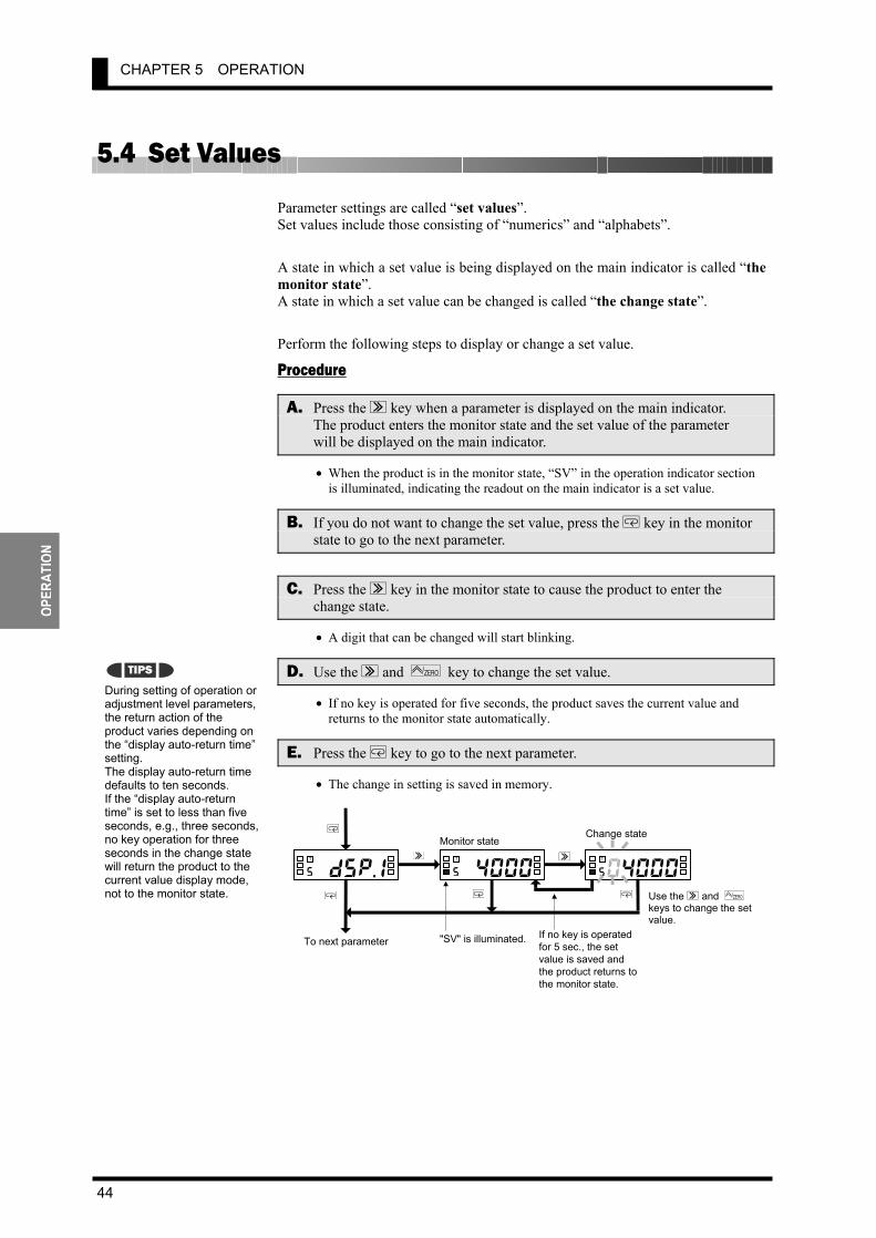
CHAPTER 5 OPERATION
44
OPER
ATIO
N
5.4 Set Values Parameter settings are called “set values”. Set values include those consisting of “numerics” and “alphabets”. A state in which a set value is being displayed on the main indicator is called “the monitor state”. A state in which a set value can be changed is called “the change state”. Perform the following steps to display or change a set value.
Procedure
A. Press the S key when a parameter is displayed on the main indicator. The product enters the monitor state and the set value of the parameter will be displayed on the main indicator.
• When the product is in the monitor state, “SV” in the operation indicator section is illuminated, indicating the readout on the main indicator is a set value.
B. If you do not want to change the set value, press the M key in the monitor state to go to the next parameter.
C. Press the S key in the monitor state to cause the product to enter the change state.
• A digit that can be changed will start blinking.
D. Use the S and ZERO/ key to change the set value.
• If no key is operated for five seconds, the product saves the current value and returns to the monitor state automatically.
E. Press the M key to go to the next parameter.
• The change in setting is saved in memory.
During setting of operation or adjustment level parameters, the return action of the product varies depending on the “display auto-return time” setting. The display auto-return time defaults to ten seconds. If the “display auto-return time” is set to less than five seconds, e.g., three seconds, no key operation for three seconds in the change state will return the product to the current value display mode, not to the monitor state.
TIPS
dsp.1s
T
4000 s
T
0 4000s
T
M
M
S S
M M Use the S and ZERO/ keys to change the set value.
Monitor stateChange state
"SV" is illuminated. If no key is operatedfor 5 sec., the set value is saved and the product returns tothe monitor state.
To next parameter
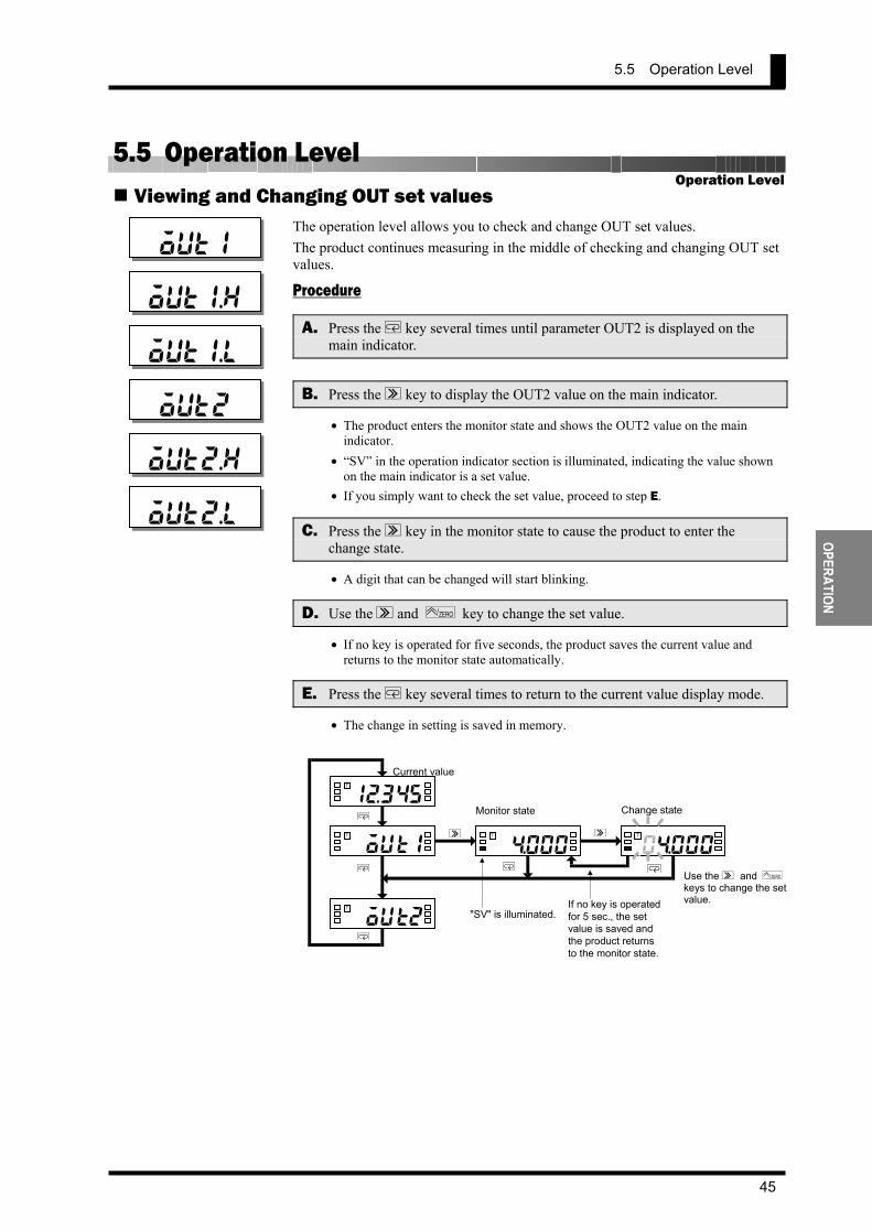
5.5 Operation Level
45
OPERATION
5.5 Operation Level Viewing and Changing OUT set values
The operation level allows you to check and change OUT set values. The product continues measuring in the middle of checking and changing OUT set values.
Procedure
A. Press the M key several times until parameter OUT2 is displayed on the main indicator.
B. Press the S key to display the OUT2 value on the main indicator.
• The product enters the monitor state and shows the OUT2 value on the main indicator.
• “SV” in the operation indicator section is illuminated, indicating the value shown on the main indicator is a set value.
• If you simply want to check the set value, proceed to step E.
C. Press the S key in the monitor state to cause the product to enter the change state.
• A digit that can be changed will start blinking.
D. Use the S and ZERO/ key to change the set value.
• If no key is operated for five seconds, the product saves the current value and returns to the monitor state automatically.
E. Press the M key several times to return to the current value display mode.
• The change in setting is saved in memory.
Operation Level
out1
out1.h
out1.l
out2
out2.h
out2.l
out18
T
$ 0 0 0 T
0$0008
T
M
M
S S
M M
out2T
Use the S and ZERO/
keys to change the setvalue.
Monitor state Change state
"SV" is illuminated. If no key is operatedfor 5 sec., the setvalue is saved andthe product returnsto the monitor state.
1B345T
M
Current value

CHAPTER 5 OPERATION
46
OPER
ATIO
N
Available OUT set values and their indications are as follows.
OUT set value Indication Description
OUT1 value out1 When the process value increases or decreases to this value, comparative output 1 is provided.
OUT1 upper-limit value out!h
OUT1 lower-limit value out!l
When the process value falls outside the range specified by these values, comparative output 1 is provided.
OUT2 value out2 When the process value increases or decreases to this value, comparative output 2 is provided.
OUT2 upper-limit value outBh
OUT2 lower-limit value outBl
When the process value falls outside the range specified by these values, comparative output 2 is provided.
Forced-zero operation The forced-zero operation allows you to shift the current value to zero forcedly. For details, refer to CHAPTER 6 FUNCTION DESCRIPTION.
Procedure (for forced-zero operation)
A. Press the ZERO/ key when a current value is displayed on the main indicator. (Release the key within one second).
• The current value will be shifted to zero. • “ZERO” in the operation indicator section is illuminated, indicating the current
value has been shifted to zero.
Procedure (for forced-zero release operation)
B. Press the ZERO/ key and hold it down for at least one second when a shifted value is displayed.
• The shifted value will be restored to the current value. • “ZERO” in the operation indicator section will go off, indicating the current
value is no longer shifted.
The forced-zero operation is not available if the input type is set to "pulse".
If the ZERO / key on the front
panel is used for executing the forced-zero operation, the forced-zero process is stored in EEPROM. But if the forced-zero operation is executed via the event input terminal or communications, the process is not stored. If the current value is not normal (e.g., the input signal is invalid, the process value is outside the displayable range, or no measurements are made), the forced-zero function is inoperative.
TIPS
Note
123$58
T
* 0 T
Press ZERO/ key and holdit down for at least 1 sec.
ZERO is illuminated.
ZERO/
ZERO/
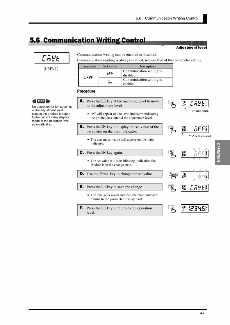
5.6 Communication Writing Control
47
OPERATION
5.6 Communication Writing Control Communication writing can be enabled or disabled. Communication reading is always enabled, irrespective of this parameter setting.
Parameter Set value Description
off Communication writing is disabled.
cmwt on
Communication writing is enabled.
Procedure
A. Press the L key at the operation level to move to the adjustment level.
• “r” will appear on the level indicator, indicating the product has entered the adjustment level.
B. Press the S key to display the set value of the parameter on the main indicator.
• The current set value will appear on the main indicator.
C. Press the S key again.
• The set value will start blinking, indication the product is in the change state.
D. Use the ZERO/ key to change the set value.
E. Press the M key to save the change.
• The change is saved and then the main indicator returns to the parameter display mode.
F. Press the L key to return to the operation level.
Adjustment level
No operation for ten seconds at the adjustment level causes the product to return to the current value display mode at the operation level automatically.
cmwt
0coffa
TS
0coona
TZERO/
0cmwta
TM
123$5a
TL
TIPS
0coffa
TS
"SV" is illuminated.
(CMWT)
0cmwtr
TL
"r" appears.
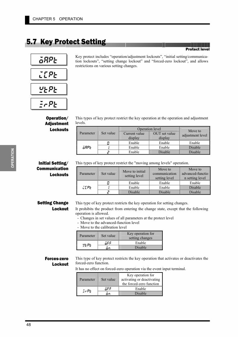
CHAPTER 5 OPERATION
48
OPER
ATIO
N
5.7 Key Protect Setting Key protect includes “operation/adjustment lockouts”, “initial setting/communica-tion lockouts”, “setting change lockout” and “forced-zero lockout”, and allows restrictions on various setting changes. This types of key protect restrict the key operation at the operation and adjustment levels.
Operation level Parameter Set value Current value
display OUT set value
display
Move to adjustment level
0 Enable Enable Enable 1 Enable Enable Disable oapt
2 Enable Disable Disable This types of key protect restrict the "moving among levels" operation.
Parameter Set value Move to initial setting level
Move to communication
setting level
Move to advanced-functio
n setting level 0 Enable Enable Enable 1 Enable Enable Disable icpt
2 Disable Disable Disable This type of key protect restricts the key operation for setting changes. It prohibits the product from entering the change state, except that the following operation is allowed. - Changes in set values of all parameters at the protect level - Move to the advanced-function level - Move to the calibration level
Parameter Set value Key operation for setting changes
off Enable wtpt
on Disable This type of key protect restricts the key operation that activates or deactivates the forced-zero function. It has no effect on forced-zero operation via the event input terminal.
Parameter Set valueKey operation for
activating or deactivating the forced-zero function
off Enable zrpt
on Disable
Protect level
Initial Setting/Communication
Lockouts
Setting ChangeLockout
Forces-zeroLockout
oapt
Operation/Adjustment
Lockouts
icpt
wtpt
zrpt
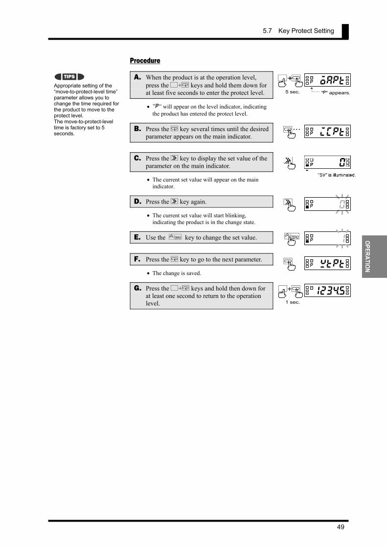
5.7 Key Protect Setting
49
OPERATION
Procedure
A. When the product is at the operation level, press the L+M keys and hold them down for at least five seconds to enter the protect level.
• “p” will appear on the level indicator, indicating the product has entered the protect level.
B. Press the M key several times until the desired parameter appears on the main indicator.
C. Press the S key to display the set value of the parameter on the main indicator.
• The current set value will appear on the main indicator.
D. Press the S key again.
• The current set value will start blinking, indicating the product is in the change state.
E. Use the ZERO/ key to change the set value.
F. Press the M key to go to the next parameter.
• The change is saved.
G. Press the L+M keys and hold then down for at least one second to return to the operation level.
Appropriate setting of the “move-to-protect-level time” parameter allows you to change the time required for the product to move to the protect level. The move-to-protect-level time is factory set to 5 seconds.
0cof0p
TS
0coo1p
TZERO/
0wtptp
TM
TIPS
123$5a
T
1 sec.
L+M
0oaptp
TL+M
"p" appears.5 sec.
0icptp
T M...
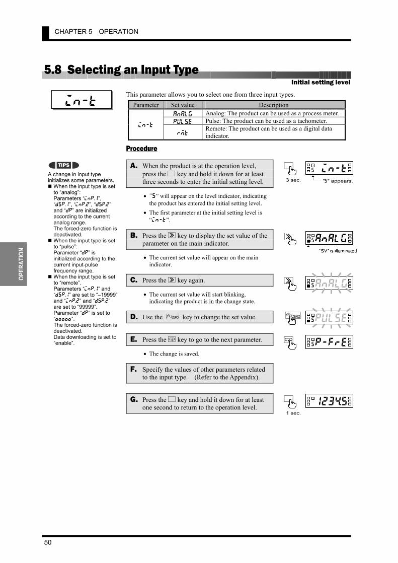
CHAPTER 5 OPERATION
50
OPER
ATIO
N
5.8 Selecting an Input Type This parameter allows you to select one from three input types.
Parameter Set value Description analg Analog: The product can be used as a process meter.pulse Pulse: The product can be used as a tachometer.
in-t rmt
Remote: The product can be used as a digital data indicator.
Procedure
A. When the product is at the operation level, press the L key and hold it down for at least three seconds to enter the initial setting level.
• “s” will appear on the level indicator, indicating the product has entered the initial setting level.
• The first parameter at the initial setting level is “in-t”.
B. Press the S key to display the set value of the parameter on the main indicator.
• The current set value will appear on the main indicator.
C. Press the S key again.
• The current set value will start blinking, indicating the product is in the change state.
D. Use the ZERO/ key to change the set value.
E. Press the M key to go to the next parameter.
• The change is saved.
F. Specify the values of other parameters related to the input type. (Refer to the Appendix).
G. Press the L key and hold it down for at least one second to return to the operation level.
Initial setting level
in-t
A change in input type initializes some parameters. When the input type is set to “analog”: Parameters “inp.1”, “dsp.1”, “inp.2”, “dsp.2” and “dp” are initialized according to the current analog range. The forced-zero function is deactivated. When the input type is set to “pulse”: Parameter “dp” is initialized according to the current input-pulse frequency range. When the input type is set to “remote”. Parameters “inp.1” and “dsp.1” are set to “–19999” and “inp.2” and “dsp.2” are set to “99999”. Parameter “dp” is set to “\\\\\”. The forced-zero function is deactivated. Data downloading is set to “enable”.
analgs
TS
pulses
TZERO/
p-fres
TM
TIPS0in-ts
TL
"s" appears.3 sec.
123$5a
TL
1 sec.

5.9 Selecting an Analog Range
51
OPERATION
5.9 Selecting an Analog Range This parameter allows you to select an analog input range. Before selecting an analog range, you must set the input type parameter to “analog”.
Parameter Set value Measuring range
4-20 4.00 to 20.00 mA/ 0.00 to 20.00 mA
1-5 1.000 to 5.000V/ 0.000 to 5.000V
5 –5.000 to 5.000V
range
10 –10.000 to 10.000V Procedure
A. When the product is at the operation level, press the L key and hold it down for at least three seconds to enter the initial setting level.
• “s” will appear on the level indicator, indicating the product has entered the initial setting level.
B. Press the M key several times until parameter “range” appears on the main indicator.
C. Press the S key to display the set value of the parameter on the main indicator.
• The set value representing the current analog range will appear on the main indicator.
D. Press the S key again.
• The set value will start blinking, indicating the product is in the change state.
E. Use the ZERO/ key to change the set value.
F. Press the M key to go to the next parameter.
• The change is saved.
G. Specify the values of other parameters related to the analog range. (Refer to the Appendix).
H. Press the L key and hold it down for at least one second to return to the operation level.
Initial setting level
range
A change in analog range initializes some parameters. Parameters “inp.1”, “dsp.1”, “inp.2”, “dsp.2” and “dp” are initialized according to the current analog range. The forced-zero function is deactivated.
a4-20s
TS
pu1-5s
TZERO/
pinp.1s
TM
TIPS0in-ts
TL
"s" appears.3 sec.
123$5a
TL
1 sec.
M...ranges
T
a4 - 2 0 s
TS
"SV" is illuminated.
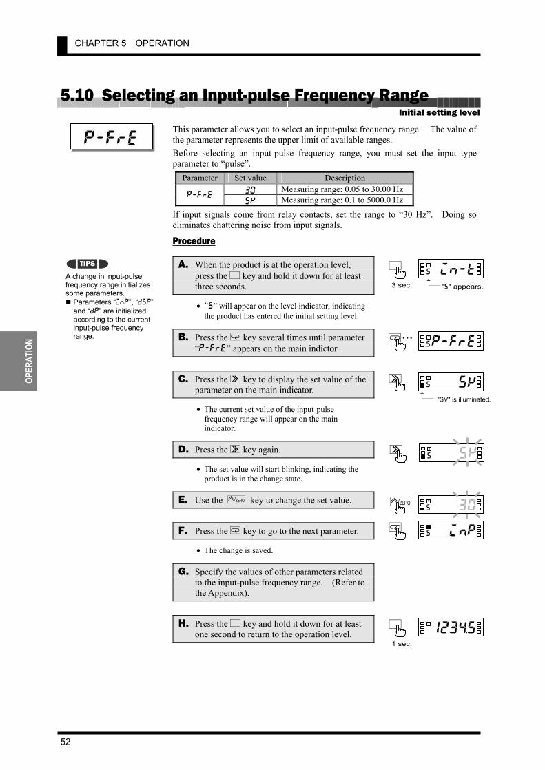
CHAPTER 5 OPERATION
52
OPER
ATIO
N
5.10 Selecting an Input-pulse Frequency Range This parameter allows you to select an input-pulse frequency range. The value of the parameter represents the upper limit of available ranges. Before selecting an input-pulse frequency range, you must set the input type parameter to “pulse”.
Parameter Set value Description 30 Measuring range: 0.05 to 30.00 Hz
p-fre 5k Measuring range: 0.1 to 5000.0 Hz
If input signals come from relay contacts, set the range to “30 Hz”. Doing so eliminates chattering noise from input signals.
Procedure
A. When the product is at the operation level, press the L key and hold it down for at least three seconds.
• “5” will appear on the level indicator, indicating the product has entered the initial setting level.
B. Press the M key several times until parameter “p-fre” appears on the main indictor.
C. Press the S key to display the set value of the parameter on the main indicator.
• The current set value of the input-pulse frequency range will appear on the main indicator.
D. Press the S key again.
• The set value will start blinking, indicating the product is in the change state.
E. Use the ZERO/ key to change the set value.
F. Press the M key to go to the next parameter.
• The change is saved.
G. Specify the values of other parameters related to the input-pulse frequency range. (Refer to the Appendix).
H. Press the L key and hold it down for at least one second to return to the operation level.
Initial setting level
p-fre
A change in input-pulse frequency range initializes some parameters. Parameters “inp”, “dsp” and “dp” are initialized according to the current input-pulse frequency range.
a4-5ks
TS
pu130s
T ZERO/
piinps
TM
TIPS0in-ts
TL
"s" appears.3 sec.
123$5a
TL
1 sec.
M...p-fres
T
a 5 k s
TS
"SV" is illuminated.
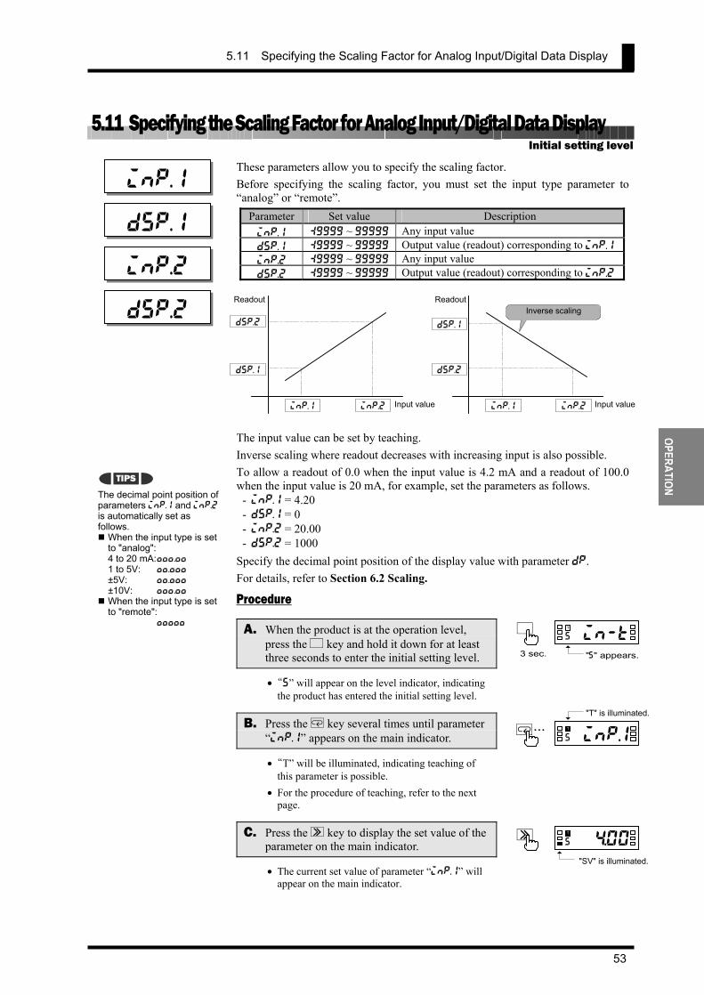
5.11 Specifying the Scaling Factor for Analog Input/Digital Data Display
53
OPERATION
5.11 Specifying the Scaling Factor for Analog Input/Digital Data Display These parameters allow you to specify the scaling factor. Before specifying the scaling factor, you must set the input type parameter to “analog” or “remote”.
Parameter Set value Description inp.1 :9999 ~ 99999 Any input value dsp.1 :9999 ~ 99999 Output value (readout) corresponding to inp.1inp.2 :9999 ~ 99999 Any input value dsp.2 :9999 ~ 99999 Output value (readout) corresponding to inp.2
The input value can be set by teaching. Inverse scaling where readout decreases with increasing input is also possible. To allow a readout of 0.0 when the input value is 4.2 mA and a readout of 100.0 when the input value is 20 mA, for example, set the parameters as follows.
- inp.1 = 4.20 - dsp.1 = 0 - inp.2 = 20.00 - dsp.2 = 1000
Specify the decimal point position of the display value with parameter dp. For details, refer to Section 6.2 Scaling.
Procedure
A. When the product is at the operation level, press the L key and hold it down for at least three seconds to enter the initial setting level.
• “s” will appear on the level indicator, indicating the product has entered the initial setting level.
B. Press the M key several times until parameter “inp.1” appears on the main indicator.
• “T” will be illuminated, indicating teaching of this parameter is possible.
• For the procedure of teaching, refer to the next page.
C. Press the S key to display the set value of the parameter on the main indicator.
• The current set value of parameter “inp.1” will appear on the main indicator.
Initial setting level
inp.1
The decimal point position of parameters inp.1 and inp.2 is automatically set as follows. When the input type is set to "analog": 4 to 20 mA: ,,,.,, 1 to 5V: ,,.,,, ±5V: ,,.,,, ±10V: ,,,.,, When the input type is set to "remote": ,,,,,
dsp.2
TIPS
0in-ts
TL
"s" appears.3 sec.
M...pinp.1s
T
"T" is illuminated.
dsp.1
inp.2
dsp.2
dsp.1
inp.1 inp.2 Input value
Readout
dsp.2
dsp.1
inp.1 inp.2 Input value
Readout Inverse scaling
a$$ 0 0 s
T
S
"SV" is illuminated.

CHAPTER 5 OPERATION
54
OPER
ATIO
N
D. Press the S key again.
• The set value starts blinking, indicating the product is in the change state.
E. Use the S and ZERO/ keys to change the set value.
F. Press the M key to go to the next parameter “dsp.1”.
• The change is saved and then “dsp.1” will appear on the main indicator.
G. Repeat steps C to F for parameters “inp.2” and “dsp.2”.
• When you finish setting of parameter “dsp.2”, parameter “dp” will appear on the main indicator.
H. Press the L key and hold it down for at least one second to return to the operation level.
The teaching function allows you to specify the value of parameters “inp.1” and “inp.2” without the need for any front panel key input.
Procedure
I. Following step C (the product is in the monitor state), press the ZERO/ key.
• “T” will start blinking, indicating the product is in teaching mode. • Key entry permits the actual process value to be displayed on the main indicator.
J. Press the ZERO/ key again.
• The actual process value is set as the input value and then the product will return to the monitor state.
• Pressing the M key instead of the ZERO / key in teaching mode cancels the teaching mode and the display on the main indicator changes to the next parameter.
pdsp.1s
TM
pdsdps
T
Teaching
00$00s
TS
00$20s
TS ZERO/
123$5a
TL
1 sec.
inp.1s T
$00s
T
0 0 $ 0 0s T
M
M
S
S
M
M
Monitor state(Actual processvalue is displayed.)
Normal change state
"T" is illuminated, indicating teaching is possible.
Next parameter
$ 0 2 s T
Teaching mode
To save the change andcause the product to enter themonitor state, press ZERO/ key.
"T" blinks.
To save no changeand go to the nextparameter, pressM key.
"T" goes off.
ZERO/

5.12 Specifying the Scaling Factor for Input Pulse Frequency
55
OPERATION
5.12 Specifying the Scaling Factor for Input Pulse Frequency These parameters allow you to specify the scaling factor. Before specifying the scaling factor, you must set the input type parameter to “pulse”.
Parameter Set value Description inp :9999 ~ 99999 Any input value dsp :9999 ~ 99999 Output value (readout) corresponding to inp
The input value can be set by teaching. To allow a readout of 10.000 when the input value is 4.2 kHz (= 4200 Hz), for example, set the parameters as follows.
- inp = 4200 - dsp = 10000
Specify the decimal point position of the display value with parameter dp. For details, refer to Section 6.2 Scaling.
Procedure
A. When the product is at the operation level, press the L key and hold it down for at least three seconds to enter the initial setting level.
• “s” will appear on the level indicator, indicating the product has entered the initial setting level.
B. Press the M key several times until parameter “inp” appears on the main indicator.
• “T” will be illuminated, indicating teaching of this parameter is possible.
• For the procedure of teaching, refer to the next page.
C. Press the S key to display the set value of the parameter on the main indicator.
• The current set value of parameter “inp” will appear on the indicator.
D. Press the S key again.
• The set value will start blinking, indicating the product is in the change state.
E. Use the S and ZERO/ keys to change the set value.
Initial setting level
inp
The decimal point position of parameter “inp” is automati-cally set depending on setting of the input-pulse frequency range as follows.
30 Hz: ,,,.,, 5 kHz: ,,,,,
dsp
55000s
TS
44200s
TS ZERO/
TIPS
0in-ts
TL
"s" appears.3 sec.
dsp
inp Input value
Readout
pii n p s
TM..."T" is illuminated.
55 0 0 0 s
TS
"SV" is illuminated.

CHAPTER 5 OPERATION
56
OPER
ATIO
N
F. Press the M key to go to the next parameter.
• The change is saved and then “dsp” will appear on the main indicator.
G. Press the L key and hold it down for at least one second to return to the operation level.
The teaching function allows you to specify the value of parameter “inp” without the need for front panel key input.
Procedure
H. Following step C (the product is in the monitor state), press the ZERO/ key.
• “T” will start blinking, indicating the product is in teaching mode. • Key entry permits the actual process value to be displayed on the main indicator.
I. Press the ZERO/ key again.
• The actual process value is set as the input value and then the product will return to the monitor state.
• Pressing the M key instead of the ZERO / key in teaching mode cancels the teaching mode and the display on the main indicator changes to the next parameter.
Teaching
pddsps
TM
123$5a
TL
1 sec.
pdsdps
T
inps T
5 00*0s
T
5 0 0 * 0s T
M
M
S
S
M
M
Monitor state(Actual processvalue is displayed.)
Normal change state
"T" is illuminated, indicating teaching ispossible.
Next parameter
5 0 0 ! 2s T
Teaching mode
To save the change andcause the product to enter themonitor state, press ZERO/ key.
"T" blinks.
To save no changeand go to the nextparameter, pressM key.
"T" goes off.
ZERO/

5.12 Specifying the Scaling Factor for Input Pulse Frequency
57
OPERATION
To minimize the scaling operation error, select such a scaling factor that permits the largest possible number of digits to be contained in scaling display values (DSP). The relationship between the scaling input and display values for input pulse frequency is represented by the following equation. Scaling display value = α (multiplication factor) × input frequency (Hz) Where α = DSP/INP α is often an indivisible number such as 5.654866… particularly when the input value is converted to a circumferential velocity. This is because such a conversion involves π. There are innumerable combinations of scaling input values (INP) and scaling display values (DSP) that result in α = 5.654866… as follows.
INP (Hz) DSP 1 2 5 10 ···
5.654866··· 11.30973··· 28.27433··· 56.54866···
On the other hand, DSPs that are programmable are limited to 5-digit integers. This means that DSPs must be rounded off to the nearest integers as follows.
INP (Hz) Programmable DSP1 2 5 10 ···
00006 00011 00028 00057
Hence, if the input frequency is 1000 Hz, the error between the scaling result and the ideal value increases with the decreasing number of digits contained in the DSP.
INP (Hz) Programmable DSP Scaling result (readout) Ideal value | Error |
1 2 5 10 ···
00006 00011 00028 00057
6000 5500 5600 5700
5655 5655 5655 5655
345 155 55 45
Select a combination of the DSP and INP so that the scaling output contains the largest possible number of digits. Doing so minimizes the scaling operation error.
How to Determine
Appropriate Scaling Factors

CHAPTER 5 OPERATION
58
OPER
ATIO
N
5.13 Specifying the Decimal Point Position This parameter allows you to specify the decimal point position of the display value.
Parameter Set value Description ,.,,,, Readouts are given to four decimal places. ,,.,,, Readouts are given to three decimal places.,,,.,, Readouts are given to two decimal places. ,,,,., Readouts are given to one decimal place.
dp
,,,,, Readouts are given as integers. Procedure
A. When the product is at the operation level, press the L key and hold it down for at least three seconds to enter the initial setting level.
• “s” will appear on the level indicator, indicating the product has entered the initial setting level.
B. Press the M key several times until parameter “dp” appears on the main indicator.
C. Press the S key to display the set value of the parameter.
• The current set value for the decimal point position will appear on the main indicator.
D. Press the S key again
• The set value will start blinking, indicating the product is in the change state.
E. Use the ZERO/ key to change the set value.
F. Press the M key to go to the next parameter.
• The change is saved.
G. Press the L key and hold it down for at least one second to return to the operation level.
Initial setting level
dp
,,,.,,s
TS
,,.,,,s
T ZERO/
out!ts
TM
0in-ts
TL
"s" appears.3 sec.
123$5a
TL
1 sec.
M...randps
T
, , ,. , , s
S
"SV" is illuminated.
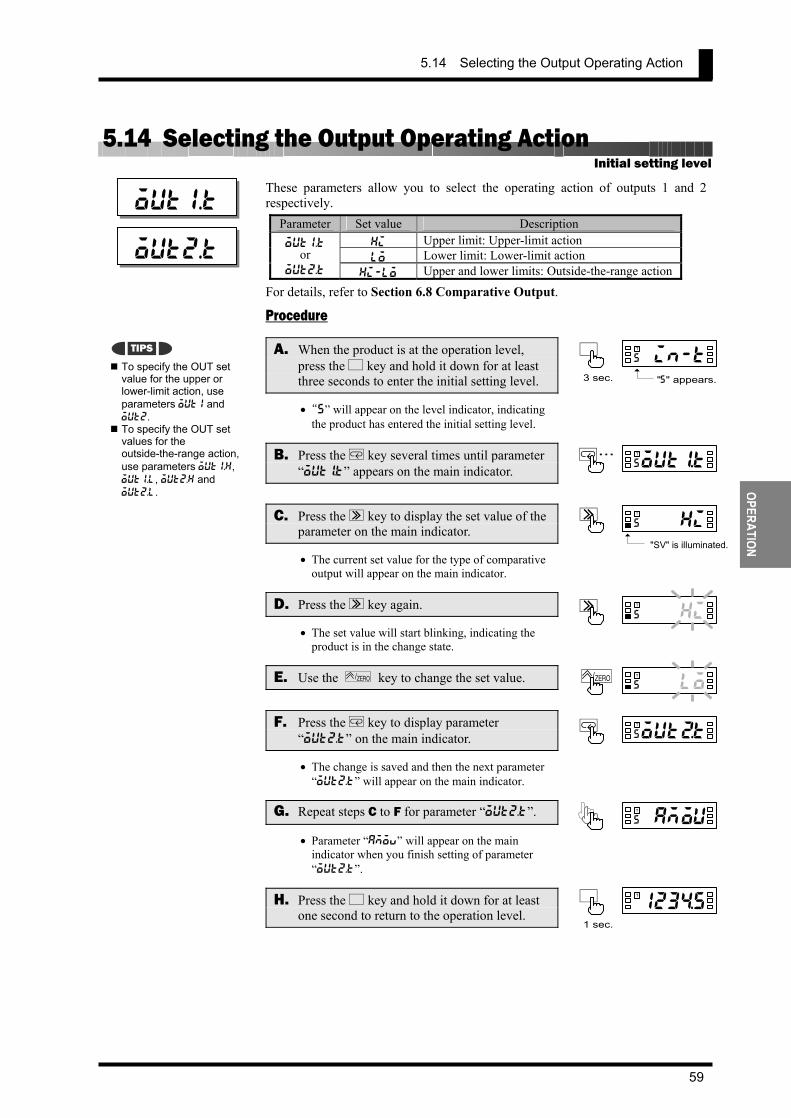
5.14 Selecting the Output Operating Action
59
OPERATION
5.14 Selecting the Output Operating Action These parameters allow you to select the operating action of outputs 1 and 2 respectively.
Parameter Set value Description hi Upper limit: Upper-limit action lo Lower limit: Lower-limit action
out1.t or
out2.t hi-lo Upper and lower limits: Outside-the-range action For details, refer to Section 6.8 Comparative Output.
Procedure
A. When the product is at the operation level, press the L key and hold it down for at least three seconds to enter the initial setting level.
• “s” will appear on the level indicator, indicating the product has entered the initial setting level.
B. Press the M key several times until parameter “out!t” appears on the main indicator.
C. Press the S key to display the set value of the parameter on the main indicator.
• The current set value for the type of comparative output will appear on the main indicator.
D. Press the S key again.
• The set value will start blinking, indicating the product is in the change state.
E. Use the ZERO/ key to change the set value.
F. Press the M key to display parameter “out2.t” on the main indicator.
• The change is saved and then the next parameter “out2.t” will appear on the main indicator.
G. Repeat steps C to F for parameter “out2.t”.
• Parameter “amov” will appear on the main indicator when you finish setting of parameter “out2.t”.
H. Press the L key and hold it down for at least one second to return to the operation level.
Initial setting level
out1.t
To specify the OUT set value for the upper or lower-limit action, use parameters out1 and out2. To specify the OUT set values for the outside-the-range action, use parameters out1.h, out1.l, out2.h and out2.l.
a4-his
TS
pu1los
TZERO/
outBts
TM
pamous
T
TIPS0in-ts
TL
"s" appears.3 sec.
123$5a
TL
1 sec.
M...out!Ts
T
out2.t
a4-h i s
TS
"SV" is illuminated.

CHAPTER 5 OPERATION
60
OPER
ATIO
N
5.15 Performing Linear Output The linear output function outputs currents or voltages proportional to measurement values as they change. Select the type of linear output. Set the maximum and minimum output measurement values to output the current or voltage for those measurement values.
Parameter Set value Description 0-20 0 to 20 mA
lset.c 4-20 4 to 20 mA 0-5 0 to 5 V 1-5 1 to 5 V lest.v 0-10 0 to 10 V
lset.h -19999 to 99999 -19999 to 99999
lset.l -19999 to 99999 -19999 to 99999 * When a linear output is mounted, the “linear current type” or “linear voltage
type” parameter can be set according to the type of linear output.. Voltage Output
Current Output
* Areas marked with an asterisk (*) are input error areas. If the “operation at input
error” parameter is set to “input error,” then the output would be like Line B. Otherwise, the output would be like Line A.
* If operation stops without performing a measurement, then the minimum value (e.g., 4 mA for the 4 to 20 mA range) is output.
Linear output level
lset.c
lset.v
lset.h
lset.l
Linear output
0V Measurement value
5V or 10V
1V
5V
Line A Line B
Linear output upper limit
Linear output lower limit
Line B
Measurement value Linear output
upper limit Linear output lower limit
Linear output
Line A
Linear output
0 mA Measurement value
20 mA
4 mA
20 mA
Line A Line B
Linear output upper limit
Linear output lower limit
Line B
Measurement value Linear output
upper limit Linear output lower limit
Linear output
Line A
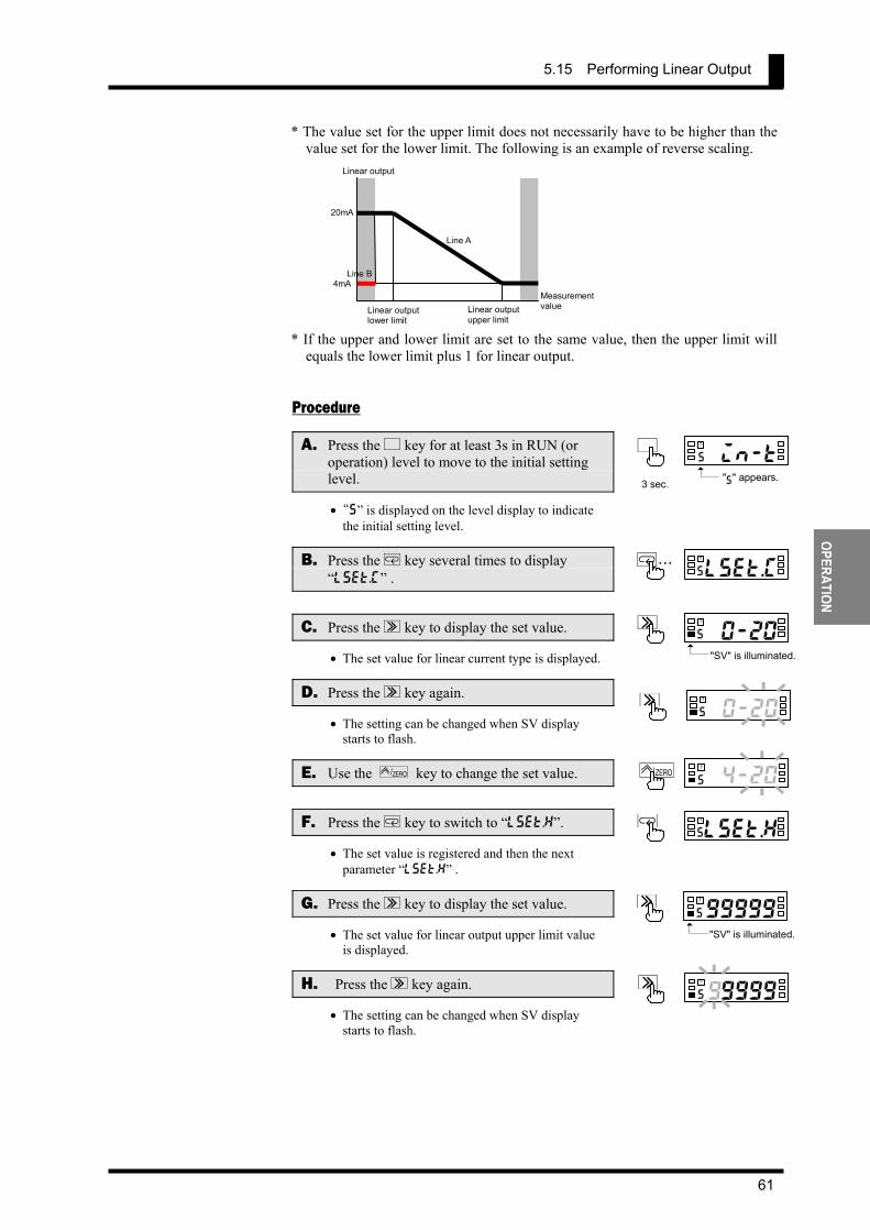
5.15 Performing Linear Output
61
OPERATION
* The value set for the upper limit does not necessarily have to be higher than the value set for the lower limit. The following is an example of reverse scaling.
* If the upper and lower limit are set to the same value, then the upper limit will
equals the lower limit plus 1 for linear output.
Procedure
A. Press the L key for at least 3s in RUN (or operation) level to move to the initial setting level.
• “s” is displayed on the level display to indicate the initial setting level.
B. Press the M key several times to display “lset.c” .
C. Press the S key to display the set value.
• The set value for linear current type is displayed.
D. Press the S key again.
• The setting can be changed when SV display starts to flash.
E. Use the ZERO/ key to change the set value.
F. Press the M key to switch to “lset.h”.
• The set value is registered and then the next parameter “lset.h” .
G. Press the S key to display the set value.
• The set value for linear output upper limit value is displayed.
H. Press the S key again.
• The setting can be changed when SV display starts to flash.
Linear output
4mA Measurement value
20mA
Linear outputlower limit
Line B
Line A
Linear outputupper limit
0i n - ts
TL
"s" appears.3 sec.
M...ous
T
lset.c
a4-s
TS
"SV" is illuminated.
0-20
a4-s
TS0-20
oulset.hs
TM
a4-s
TS
"SV" is illuminated.
99999
a4-s
TS99999
4-20s
TZERO/

CHAPTER 5 OPERATION
62
OPER
ATIO
N
I. Use the S ZERO/ [UP] key to change the set value.
J. Press the M key to switch to “lset.l”.
• The set value is registered.
K. Repeat steps G to J to set “lset.l”.
• The next parameter is displayed after “lset.l” is set.
L. Press the L key for at least 1s to return to RUN (or operation) level.
elset.ls
TM
amous
T
1234.5a
T
L
1 sec.
400005s
T
S ZERO/
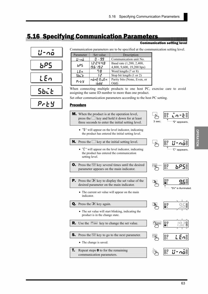
5.16 Specifying Communication Parameters
63
OPERATION
5.16 Specifying Communication Parameters Communication parameters are to be specified at the communication setting level.
Parameter Set value Description u-no 0 ~ 99 Communication unit No.
bps 1.2/2.4/4.8 /9.6/19.2
Baud rate (1,200, 2,400, 4,800, 9,600, 19,200 bps)
len 7/8 Word length (7 or 8) sbit 1/2 Stop bit length (1 or 2)
prty none/even/odd
Parity bits (None, Even, or Odd)
When connecting multiple products to one host PC, exercise care to avoid assigning the same ID number to more than one product. Set other communication parameters according to the host PC setting.
Procedure
M. When the product is at the operation level, press the L key and hold it down for at least three seconds to enter the initial setting level.
• “s” will appear on the level indicator, indicating the product has entered the initial setting level.
N. Press the L key at the initial setting level.
• “c” will appear on the level indicator, indicating the product has entered the communication setting level.
O. Press the M key several times until the desired parameter appears on the main indicator.
P. Press the S key to display the set value of the desired parameter on the main indicator.
• The current set value will appear on the main indicator.
Q. Press the S key again.
• The set value will start blinking, indicating the product is in the change state.
R. Use the ZERO/ key to change the set value.
S. Press the M key to go to the next parameter.
• The change is saved.
T. Repeat steps 0 to for the remaining communication parameters.
Communication setting level
u-no
bps
len
sbit
prty
a4-)6c
TS
pu1)2c
TZERO/
oulenc
TM
pu-noc
T
0in-ts
TL
"s" appears.3 sec.
0u-noc
TL
"c" appears.
M...oubpsc
T
-)6c
T
S
"SV" is illuminated.

CHAPTER 5 OPERATION
64
OPER
ATIO
N
U. Press the L key to return to the initial setting level.
V. Press the L key and hold it down for at least one second to return to the operation level.
0in-ts
TL
123$5a
TL
1 sec.
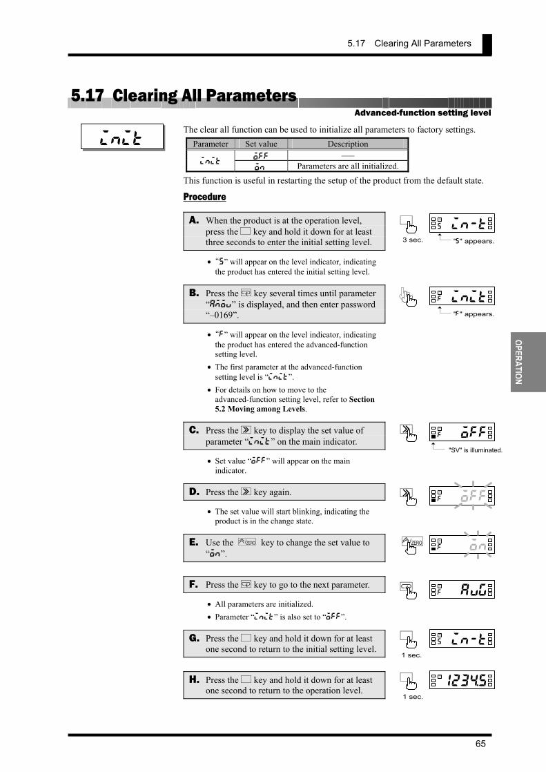
5.17 Clearing All Parameters
65
OPERATION
5.17 Clearing All Parameters The clear all function can be used to initialize all parameters to factory settings.
Parameter Set value Description off –––
init on Parameters are all initialized.
This function is useful in restarting the setup of the product from the default state.
Procedure
A. When the product is at the operation level, press the L key and hold it down for at least three seconds to enter the initial setting level.
• “s” will appear on the level indicator, indicating the product has entered the initial setting level.
B. Press the M key several times until parameter “amov” is displayed, and then enter password “–0169”.
• “f” will appear on the level indicator, indicating the product has entered the advanced-function setting level.
• The first parameter at the advanced-function setting level is “init”.
• For details on how to move to the advanced-function setting level, refer to Section 5.2 Moving among Levels.
C. Press the S key to display the set value of parameter “init” on the main indicator.
• Set value “off” will appear on the main indicator.
D. Press the S key again.
• The set value will start blinking, indicating the product is in the change state.
E. Use the ZERO/ key to change the set value to “on”.
F. Press the M key to go to the next parameter.
• All parameters are initialized. • Parameter “init” is also set to “off”.
G. Press the L key and hold it down for at least one second to return to the initial setting level.
H. Press the L key and hold it down for at least one second to return to the operation level.
Advanced-function setting level
init
a4offf
TS
pu1onf
TZERO/
ouavgf
TM
0in-ts
TL
"s" appears.3 sec.
0initf
T
"f" appears.
0in-ts
TL
1 sec.
123$5a
TL
1 sec.
a4o f f f
TS
"SV" is illuminated.
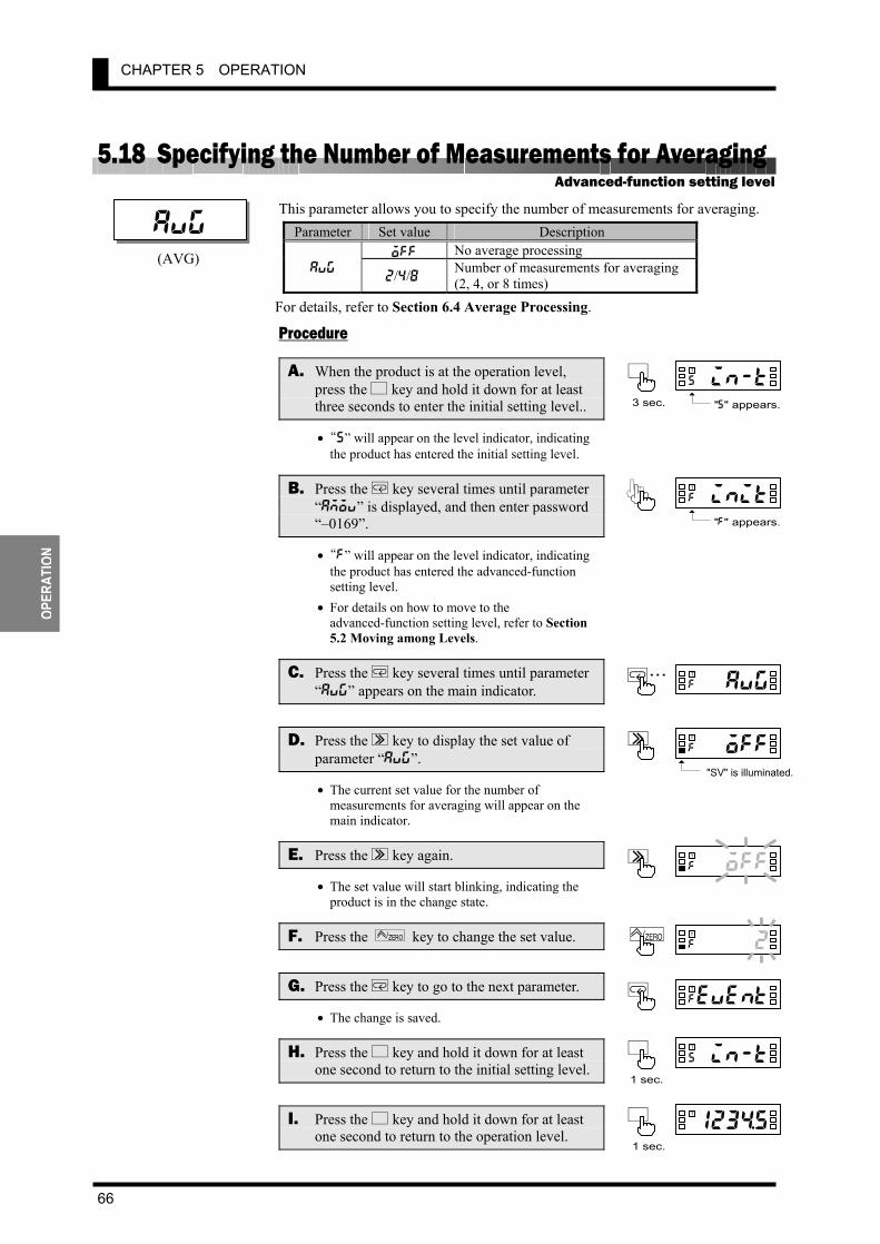
CHAPTER 5 OPERATION
66
OPER
ATIO
N
5.18 Specifying the Number of Measurements for Averaging This parameter allows you to specify the number of measurements for averaging.
Parameter Set value Description off No average processing
avg 2/4/8 Number of measurements for averaging
(2, 4, or 8 times) For details, refer to Section 6.4 Average Processing.
Procedure
A. When the product is at the operation level, press the L key and hold it down for at least three seconds to enter the initial setting level..
• “s” will appear on the level indicator, indicating the product has entered the initial setting level.
B. Press the M key several times until parameter “amov” is displayed, and then enter password “–0169”.
• “f” will appear on the level indicator, indicating the product has entered the advanced-function setting level.
• For details on how to move to the advanced-function setting level, refer to Section 5.2 Moving among Levels.
C. Press the M key several times until parameter “avg” appears on the main indicator.
D. Press the S key to display the set value of parameter “avg”.
• The current set value for the number of measurements for averaging will appear on the main indicator.
E. Press the S key again.
• The set value will start blinking, indicating the product is in the change state.
F. Press the ZERO/ key to change the set value.
G. Press the M key to go to the next parameter.
• The change is saved.
H. Press the L key and hold it down for at least one second to return to the initial setting level.
I. Press the L key and hold it down for at least one second to return to the operation level.
Advanced-function setting level
avg
a4offf
TS
pu1o2f
T ZERO/
eventf
TM
(AVG)
0in-ts
TL
"s" appears.3 sec.
0initf
T
"f" appears.
0in-ts
TL
1 sec.
123$5a
TL
1 sec.
M...ouavgf
T
a4o f f f
TS
"SV" is illuminated.

5.19 Specifying the Function of the Event Input
67
OPERATION
5.19 Specifying the Function of the Event Input When the input type has been set to "analog" or "remote", this parameter allows you to specify the function of the event input (terminal ). Before specifying the function of the event input, you must set the input type to “analog” or “remote”.
Parameter Set value Description hold HOLD: The current process value is held.
event zero
ZERO: The current process value is forcedly shifted to zero.
For details, refer to Section 6.5 Process Value Hold. Procedure
A. When the product is at the operation level, press the L key and hold it down for at least three seconds to enter the initial setting level..
• “s” will appear on the level indicator, indicating the product has entered the initial setting level.
B. Press the M key several times until parameter “amov” is displayed, and then enter password “–0169”.
• “f” will appear on the level indicator, indicating the product has entered the advanced-function setting level.
• For details on how to move to the advanced-function setting level, refer to Section 5.2 Moving among Levels.
C. Press the M key several times until parameter “event” appears on the main indicator.
D. Press the S key to display the set value of parameter “event” on the main indicator.
• The current set value will appear on the main indicator.
E. Press the S key again.
• The set value will start blinking, indicating the product is in the change state.
F. Use the ZERO/ key to change the set value.
G. Press the M key to go to the next parameter.
• The change is saved.
H. Press the L key and hold it down for at least one second to return to the initial setting level.
event
aholdf
TS
pzerof
TZERO/
ehys1f
TM
(EVENT)
Advanced-function setting level
0in-ts
TL
"s" appears.3 sec.
0initf
T
"f" appears.
0in-ts
TL
1 sec.
M...eventf
T
ah o l d f
TS
"SV" is illuminated.

CHAPTER 5 OPERATION
68
OPER
ATIO
N
I. Press the L key and hold it down for at least one second to return to the operation level. 123$5a
TL
1 sec.

5.20 Specifying the Hysteresis
69
OPERATION
5.20 Specifying the Hysteresis These parameters allow you to specify the hysteresis for each of comparative outputs 1 and 2.
Parameter Set value Description hys∗ 0 ~ 9999 0 to 9999: Hysteresis
The setting of the decimal point position parameter at the initial setting level is reflected on the decimal point position of the hysteresis. For details, refer to Section 6.9 Hysteresis. Procedure
A. When the product is at the operation level, press the L key and hold it down for at least three seconds to enter the initial setting level.
• “s” will appear on the level indicator, indicating the product has entered the initial setting level.
B. Press the M key several times until parameter “amov” is displayed, and then enter password “–0169”.
• “f” will appear on the level indicator, indicating the product has entered the advanced-function setting level.
• For details on how to move to the advanced-function setting level, refer to Section 5.2 Moving among Levels.
C. Press the M key several times until parameter “hys1” appears on the main indicator.
D. Press the S key to display the set value of parameter “hys1” on the main indicator.
• The current set value will appear on the main indicator.
E. Press the S key again.
• The set value will start blinking, indicating the product is in the change state.
F. Use the S and ZERO/ keys to change the set value.
G. Press the M key to go to parameter “hys2”.
• The change is saved.
H. Repeat steps D to G for parameter “hys2”.
• The next parameter will appear on the main indicator when you finish setting of parameter “hys2”.
hys1
a0001f
TS
40005f
TS ZERO/
ehys2f
TM
colorf
T
A hysteresis setting of “0” is assumed to be a hysteresis setting of “1”.
TIPS
Advanced-function setting level
0initf
T
"f" appears.
0in-ts
TL
"s" appears.3 sec.
M...ehys1f
T
hys2
ahol1 f
TS
"SV" is illuminated.

CHAPTER 5 OPERATION
70
OPER
ATIO
N
I. Press the L key and hold it down for at least one second to return to the initial setting level.
J. Press the L key and hold it down for at least one second to return to the operation level.
123$5a
TL
1 sec.
0in-ts
TL
1 sec.
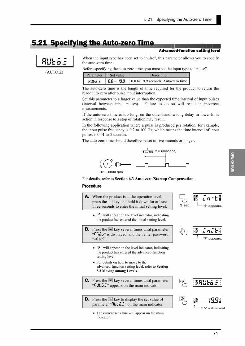
5.21 Specifying the Auto-zero Time
71
OPERATION
5.21 Specifying the Auto-zero Time When the input type has been set to "pulse", this parameter allows you to specify the auto-zero time. Before specifying the auto-zero time, you must set the input type to “pulse”.
Parameter Set value Description
auto.z 0.0 ~ 19.9 0.0 to 19.9 seconds: Auto-zero time
The auto-zero time is the length of time required for the product to return the readout to zero after pulse input interruption. Set this parameter to a larger value than the expected time interval of input pulses (interval between input pulses). Failure to do so will result in incorrect measurements. If the auto-zero time is too long, on the other hand, a long delay in lower-limit action in response to a stop of rotation may result. In the following application where a pulse is produced per rotation, for example, the input pulse frequency is 0.2 to 100 Hz, which means the time interval of input pulses is 0.01 to 5 seconds. The auto-zero time should therefore be set to five seconds or longer.
For details, refer to Section 6.3 Auto-zero/Startup Compensation. Procedure
A. When the product is at the operation level, press the L key and hold it down for at least three seconds to enter the initial setting level.
• “s” will appear on the level indicator, indicating the product has entered the initial setting level.
B. Press the M key several times until parameter “amov” is displayed, and then enter password “–0169”.
• “f” will appear on the level indicator, indicating the product has entered the advanced-function setting level.
• For details on how to move to the advanced-function setting level, refer to Section 5.2 Moving among Levels.
C. Press the M key several times until parameter “auto.z” appears on the main indicator.
D. Press the S key to display the set value of parameter “auto.z” on the main indicator.
• The current set value will appear on the main indicator.
auto.z
(AUTO.Z)
Advanced-function setting level
0in-ts
TL
"s" appears.3 sec.
0initf
T
"f" appears.
12 ~ 6000 rpm
12 ÷ 601
= 5 (seconds)
M...auto.zf
T
ah1 ) 9 f
TS
"SV" is illuminated.

CHAPTER 5 OPERATION
72
OPER
ATIO
N
E. Press the S key again.
• The set value will start blinking, indicating the product is in the change state.
F. Use the S and ZERO/ keys to change the set value.
G. Press the M key to go to the next parameter.
• The change is saved and the next parameter will appear on the main indicator.
H. Press the L key and hold it down for at least one second to return to the initial setting level.
I. Press the L key and hold it down for at least one second to return to the operation level.
a01)9f
TS
400%9f
TS ZERO/
s-tmrf
TM
0in-ts
TL
1 sec.
123$5a
TL
1 sec.
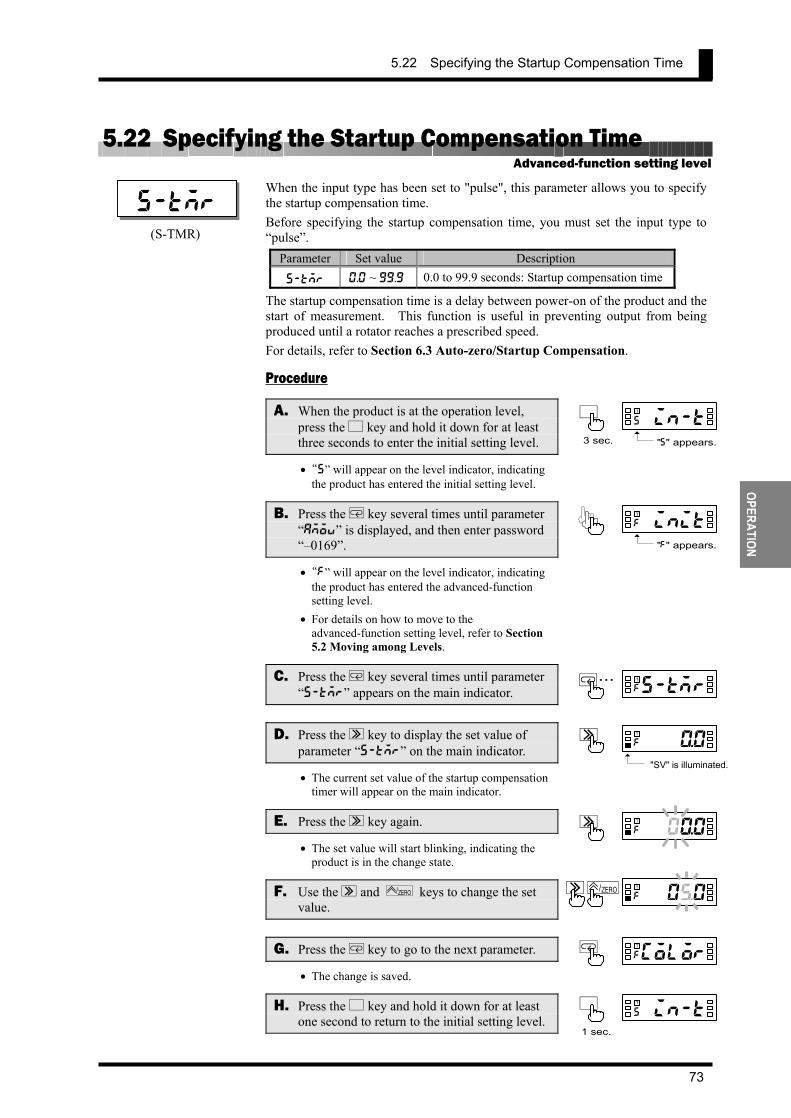
5.22 Specifying the Startup Compensation Time
73
OPERATION
5.22 Specifying the Startup Compensation Time When the input type has been set to "pulse", this parameter allows you to specify the startup compensation time. Before specifying the startup compensation time, you must set the input type to “pulse”.
Parameter Set value Description
s-tmr 0.0 ~ 99.9 0.0 to 99.9 seconds: Startup compensation time
The startup compensation time is a delay between power-on of the product and the start of measurement. This function is useful in preventing output from being produced until a rotator reaches a prescribed speed. For details, refer to Section 6.3 Auto-zero/Startup Compensation.
Procedure
A. When the product is at the operation level, press the L key and hold it down for at least three seconds to enter the initial setting level.
• “s” will appear on the level indicator, indicating the product has entered the initial setting level.
B. Press the M key several times until parameter “amov” is displayed, and then enter password “–0169”.
• “f” will appear on the level indicator, indicating the product has entered the advanced-function setting level.
• For details on how to move to the advanced-function setting level, refer to Section 5.2 Moving among Levels.
C. Press the M key several times until parameter “s-tmr” appears on the main indicator.
D. Press the S key to display the set value of parameter “s-tmr” on the main indicator.
• The current set value of the startup compensation timer will appear on the main indicator.
E. Press the S key again.
• The set value will start blinking, indicating the product is in the change state.
F. Use the S and ZERO/ keys to change the set value.
G. Press the M key to go to the next parameter.
• The change is saved.
H. Press the L key and hold it down for at least one second to return to the initial setting level.
s-tmr
a00*0f
TS
colorf
TM
400%0f
TS ZERO/
(S-TMR)
Advanced-function setting level
0in-ts
TL
"s" appears.3 sec.
0initf
T
"f" appears.
0in-ts
TL
1 sec.
M...s-tmrf
T
ah9* 0 f
TS
"SV" is illuminated.

CHAPTER 5 OPERATION
74
OPER
ATIO
N
I. Press the L key and hold it down for at least one second to return to the operation level.
123$5a
TL
1 sec.
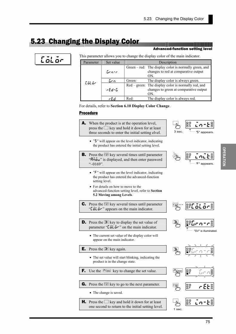
5.23 Changing the Display Color
75
OPERATION
5.23 Changing the Display Color This parameter allows you to change the display color of the main indicator.
Parameter Set value Description
grn-r Green – red: The display color is normally green, and
changes to red at comparative output ON.
grn Green: The display color is always green.
red-g
Red – green: The display color is normally red, and changes to green at comparative output ON.
color
red Red: The display color is always red. For details, refer to Section 6.10 Display Color Change. Procedure
A. When the product is at the operation level, press the L key and hold it down for at least three seconds to enter the initial setting elvel.
• “s” will appear on the level indicator, indicating the product has entered the initial setting level.
B. Press the M key several times until parameter “amov” is displayed, and then enter password “–0169”.
• “f” will appear on the level indicator, indicating the product has entered the advanced-function setting level.
• For details on how to move to the advanced-function setting level, refer to Section 5.2 Moving among Levels.
C. Press the M key several times until parameter “color” appears on the main indicator.
D. Press the S key to display the set value of parameter “color” on the main indicator.
• The current set value of the display color will appear on the main indicator.
E. Press the S key again.
• The set value will start blinking, indicating the product is in the change state.
F. Use the ZERO/ key to change the set value.
G. Press the M key to go to the next parameter.
• The change is saved.
H. Press the L key and hold it down for at least one second to return to the initial setting level.
color
grn-rf
TS
pzgrnf
TZERO/
coretf
TM
Advanced-function setting level
0in-ts
TL
"s" appears.3 sec.
0initf
T
"f" appears.
0in-ts
TL
1 sec.
M...colorf
T
g r n - r f
TS
"SV" is illuminated.

CHAPTER 5 OPERATION
76
OPER
ATIO
N
I. Press the L key and hold it down for at least one second to return to the operation level.
123$5a
TL
1 sec.
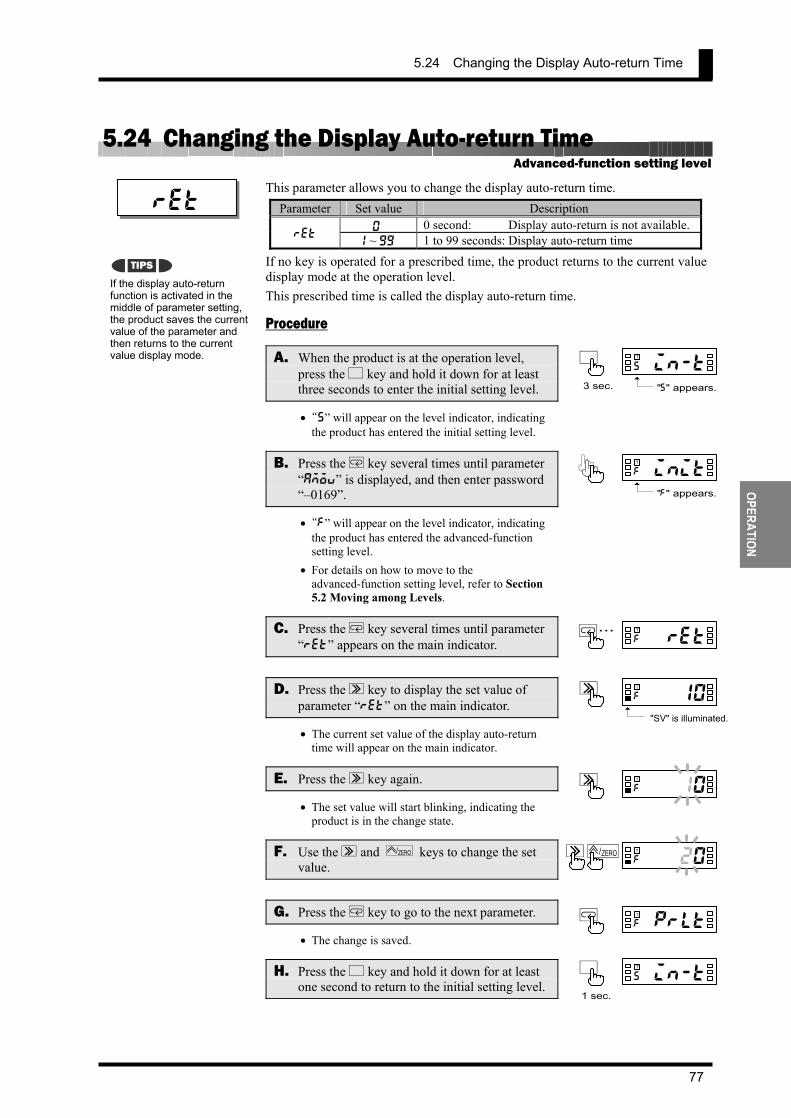
5.24 Changing the Display Auto-return Time
77
OPERATION
5.24 Changing the Display Auto-return Time This parameter allows you to change the display auto-return time.
Parameter Set value Description 0 0 second: Display auto-return is not available.
ret 1 ~ 99 1 to 99 seconds: Display auto-return time
If no key is operated for a prescribed time, the product returns to the current value display mode at the operation level. This prescribed time is called the display auto-return time.
Procedure
A. When the product is at the operation level, press the L key and hold it down for at least three seconds to enter the initial setting level.
• “s” will appear on the level indicator, indicating the product has entered the initial setting level.
B. Press the M key several times until parameter “amov” is displayed, and then enter password “–0169”.
• “f” will appear on the level indicator, indicating the product has entered the advanced-function setting level.
• For details on how to move to the advanced-function setting level, refer to Section 5.2 Moving among Levels.
C. Press the M key several times until parameter “ret” appears on the main indicator.
D. Press the S key to display the set value of parameter “ret” on the main indicator.
• The current set value of the display auto-return time will appear on the main indicator.
E. Press the S key again.
• The set value will start blinking, indicating the product is in the change state.
F. Use the S and ZERO/ keys to change the set value.
G. Press the M key to go to the next parameter.
• The change is saved.
H. Press the L key and hold it down for at least one second to return to the initial setting level.
ret
a0010f
TS
40020f
TS ZERO/
cprltf
TM
If the display auto-return function is activated in the middle of parameter setting, the product saves the current value of the parameter and then returns to the current value display mode.
TIPS
Advanced-function setting level
0in-ts
TL
"s" appears.3 sec.
0initf
T
"f" appears.
0in-ts
TL
1 sec.
M...coretf
T
ah91 0 f
TS
"SV" is illuminated.

CHAPTER 5 OPERATION
78
OPER
ATIO
N
I. Press the L key and hold it down for at least one second to return to the operation level. 123$5a
TL
1 sec.
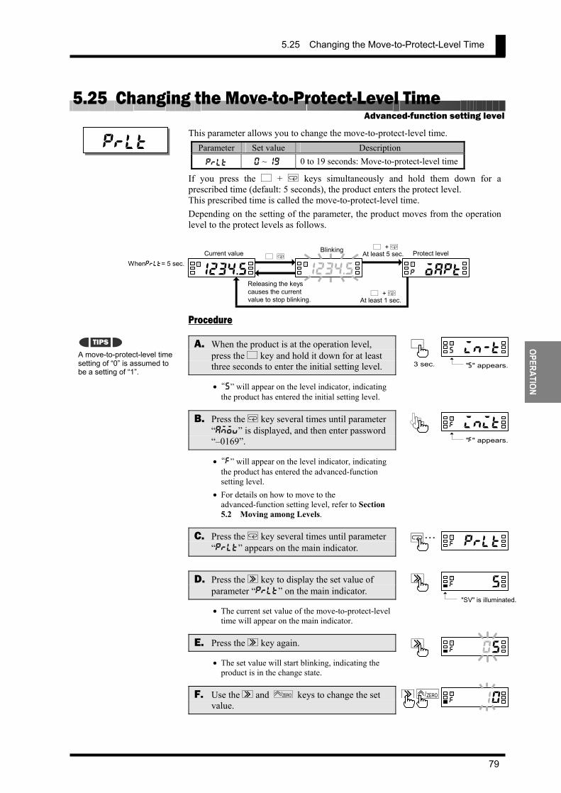
5.25 Changing the Move-to-Protect-Level Time
79
OPERATION
5.25 Changing the Move-to-Protect-Level Time This parameter allows you to change the move-to-protect-level time.
Parameter Set value Description
prlt 0 ~ 19 0 to 19 seconds: Move-to-protect-level time
If you press the L + M keys simultaneously and hold them down for a prescribed time (default: 5 seconds), the product enters the protect level. This prescribed time is called the move-to-protect-level time. Depending on the setting of the parameter, the product moves from the operation level to the protect levels as follows.
Procedure
A. When the product is at the operation level, press the L key and hold it down for at least three seconds to enter the initial setting level.
• “s” will appear on the level indicator, indicating the product has entered the initial setting level.
B. Press the M key several times until parameter “amov” is displayed, and then enter password “–0169”.
• “f” will appear on the level indicator, indicating the product has entered the advanced-function setting level.
• For details on how to move to the advanced-function setting level, refer to Section 5.2 Moving among Levels.
C. Press the M key several times until parameter “prlt” appears on the main indicator.
D. Press the S key to display the set value of parameter “prlt” on the main indicator.
• The current set value of the move-to-protect-level time will appear on the main indicator.
E. Press the S key again.
• The set value will start blinking, indicating the product is in the change state.
F. Use the S and ZERO/ keys to change the set value.
prlt
a0005f
TS
40010f
TS ZERO/
A move-to-protect-level time setting of “0” is assumed to be a setting of “1”.
TIPS
Advanced-function setting level
0in-ts
TL
"s" appears.3 sec.
0initf
T
"f" appears.
M...cprltf
T
1234.5 T
1234.5 T
0oaptp
T
L MCurrent value Blinking Protect level
L + M At least 1 sec.
Whenprlt= 5 sec.
Releasing the keys causes the current value to stop blinking.
L + M At least 5 sec.
ah915 f
TS
"SV" is illuminated.

CHAPTER 5 OPERATION
80
OPER
ATIO
N
G. Press the M key to go to the next parameter.
• The change is saved.
H. Press the L key and hold it down for at least one second to return to the initial setting level.
I. Press the L key and hold it down for at least one second to return to the operation level.
csdwtf
TM
0in-ts
TL
1 sec.
123$5a
TL
1 sec.

5.26 Changing the Send Waiting Time
81
OPERATION
5.26 Changing the Send Waiting Time This parameter allows you to change the send waiting time.
Parameter Set value Description
sdwt 0 ~ 99 0 to 99 milliseconds: Send waiting time
The send waiting time is the time between reception of a command frame from the host PC and return of a response frame to the host PC. To optimize the responsivity, you should set the send waiting time somewhat longer than the processing time that is required for the host PC to be ready for reception of a response frame after it sends a command frame.
Procedure
A. When the product is at the operation level, press the L key and hold it down for at least three seconds to enter the initial setting level.
• “s” will appear on the level indicator, indicating the product has entered the initial setting level.
B. Press the M key several times until parameter “amov” is displayed, and then enter password “–0169”.
• “f” will appear on the level indicator, indicating the product has entered the advanced-function setting level.
• For details on how to move to the advanced-function setting level, refer to Section 5.2 Moving among Levels.
C. Press the M key several times until parameter “sdwt” appears on the main indicator.
D. Press the S key to display the set value of parameter “sdwt” on the main indicator.
• The current set value of the send waiting time will appear on the main indicator.
E. Press the S key again.
• The set value will start blinking, indicating the product is in the change state.
F. Use the S and ZERO/ keys to change the set value.
sdwt
a0020f
TS
40030f
TS ZERO/
(SDWT)
Advanced-function setting level
0in-ts
TL
"s" appears.3 sec.
0initf
T
"f" appears.
M...csdwtf
T
Sending a
command frame In
preparation for reception
Receiving a response frame
Receiving a command frame Sending a response frame Wait for send
Host PC
K3GN
ah92 0 f
TS
"SV" is illuminated.

CHAPTER 5 OPERATION
82
OPER
ATIO
N
G. Press the M key to go to the next parameter.
• The change is saved.
H. Press the L key and hold it down for at least one second to return to the initial setting level.
I. Press the L key and hold it down for at least one second to return to the operation level.
ccmovf
TM
0in-ts
TL
1 sec.
123$5a
TL
1 sec.

5.26 Changing the Send Waiting Time
83
FUNCTION DESCRIPTION
6 FUNCTION DESCRIPTION
6.1 Measurement ・・・・・・・・・・・・・・・・・・・・・・・・・・・・・・・・・・・・・・・・・・・・・ 84 Analog Input Signal/Pulse Input Signal/ Digital Data from PLC/PC
6.2 Scaling ・・・・・・・・・・・・・・・・・・・・・・・・・・・・・・・・・・・・・・・・・・・・・・・・・・ 86 6.3 Auto-zero/Startup Compensation ・・・・・・・・・・・・・・・・・・・・・・・・・・・ 88
Auto-zero/Startup Compensation 6.4 Average Processing ・・・・・・・・・・・・・・・・・・・・・・・・・・・・・・・・・・・・・・・ 89 6.5 Event Input/Pulse Input・・・・・・・・・・・・・・・・・・・・・・・・・・・・・・・・・・・・ 90 6.6 Process Value Hold ・・・・・・・・・・・・・・・・・・・・・・・・・・・・・・・・・・・・・・・ 91 6.7 Forced-zero ・・・・・・・・・・・・・・・・・・・・・・・・・・・・・・・・・・・・・・・・・・・・・・ 92 6.8 Comparative Output・・・・・・・・・・・・・・・・・・・・・・・・・・・・・・・・・・・・・・・ 93 6.9 Hysteresis・・・・・・・・・・・・・・・・・・・・・・・・・・・・・・・・・・・・・・・・・・・・・・・・ 94 6.10 Display Color Change ・・・・・・・・・・・・・・・・・・・・・・・・・・・・・・・・・・・・・ 95
This chapter describes available functions of the product.
CHAPTER
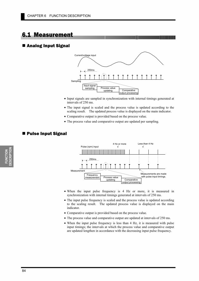
CHAPTER 6 FUNCTION DESCRIPTION
84
FUNC
TION
DE
SCRI
PTIO
N
6.1 Measurement
Analog Input Signal
• Input signals are sampled in synchronization with internal timings generated at intervals of 250 ms.
• The input signal is scaled and the process value is updated according to the scaling result. The updated process value is displayed on the main indicator.
• Comparative output is provided based on the process value. • The process value and comparative output are updated per sampling.
Pulse Input Signal
• When the input pulse frequency is 4 Hz or more, it is measured in
synchronization with internal timings generated at intervals of 250 ms. • The input pulse frequency is scaled and the process value is updated according
to the scaling result. The updated process value is displayed on the main indicator.
• Comparative output is provided based on the process value. • The process value and comparative output are updated at intervals of 250 ms. • When the input pulse frequency is less than 4 Hz, it is measured with pulse
input timings; the intervals at which the process value and comparative output are updated lengthen in accordance with the decreasing input pulse frequency.
Current/voltage input
Sampling
250ms
Input signal sampling Process value
updating Comparative output processing
Pulse (rpm) input
4 Hz or more Less than 4 Hz
250ms
Frequencymeasurement Process value
updating Comparative output processing
Measurement Measurements are madewith pulse input timings.

6.1 Measurement
85
FUNCTION DESCRIPTION
Digital Data from PLC/PC
When the product is used as a remote indicator, the host PC not only provides logging of measured data and remote control to the product but also acts as input equipment for the product. The product performs measurement, scaling and comparative output processing. The product measures serial data as follows.
• Data from the host PC is stored with timings of data transmission. When new
data is received, old data is replaced with the new one. • Stored data is fetched as input values in synchronization with internal timings
generated at intervals of 250 ms, irrespective of timing signals received from the host PC.
• The input value is scaled and the process value is updated according to the scaling result. The updated process value is displayed on the main indicator.
• Comparative output is provided based on the process value. • The process value and comparative output are updated with internal timings
generated at intervals of 250 ms.
Sampling
250ms
Input signalsampling Process value
updating Comparative output processing
Data from host PC
1 2 3 4
3 4 4 4
5
5
((((88
T
K3GN withcommunication function
Serial data as input signals

CHAPTER 6 FUNCTION DESCRIPTION
86
FUNC
TION
DE
SCRI
PTIO
N
6.2 Scaling Scaling is to convert sampled input values to process values in sequence using a predetermined scaling formula.
Scaling allows conversion of input values to process values in easy-to-understand notation. The scaling formula for analog input and digital data is as follows.
121221
1212
INPINPDSPINPDSPINPinp
INPINPDSPDSPdsp
−⋅−⋅+
−−=
Where; INP1: Input value DSP1: Process value corresponding to input value INP1 INP2: Input value DSP2: Process value corresponding to input value INP2 inp: Input value sampled dsp: Process value corresponding to inp Enter INP1, DSP1, INP2 and DSP2 to specify the scaling factor. This way of specifying the scaling factor permits flexible scaling; inverse scaling where the process value decreases with the increasing input value is also possible.
For details on how to specify the scaling factor, refer to Section 5.11 Specifying the Scaling Factor for Analog Input/Digital Data Display.
Scaling Formulafor Analog Inputand Digital Data
Processvalue
Input value
Flexible scaling
Input value(scaling input)
Process value (scaling output)
Conversionequation
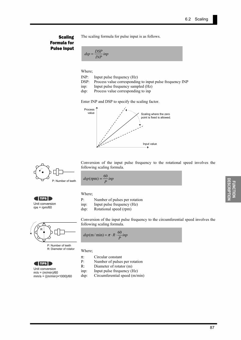
6.2 Scaling
87
FUNCTION DESCRIPTION
The scaling formula for pulse input is as follows.
inpINPDSPdsp =
Where; INP: Input pulse frequency (Hz) DSP: Process value corresponding to input pulse frequency INP inp: Input pulse frequency sampled (Hz) dsp: Process value corresponding to inp Enter INP and DSP to specify the scaling factor.
Conversion of the input pulse frequency to the rotational speed involves the following scaling formula.
inpP
dsp 60)rpm( =
Where; P: Number of pulses per rotation inp: Input pulse frequency (Hz) dsp: Rotational speed (rpm) Conversion of the input pulse frequency to the circumferential speed involves the following scaling formula.
inpP
Rdsp 60min)/m( ⋅⋅= π
Where; π: Circular constant P: Number of pulses per rotation R: Diameter of rotator (m) inp: Input pulse frequency (Hz) dsp: Circumferential speed (m/min)
Scaling Formula for Pulse Input
Unit conversion rps = rpm/60
Unit conversion m/s = (m/min)/60 mm/s = (m/min)×1000/60
TIPS
TIPS
Processvalue
Input value
Scaling where the zero point is fixed is allowed.
P: Number of teeth
P: Number of teeth R: Diameter of rotator
R
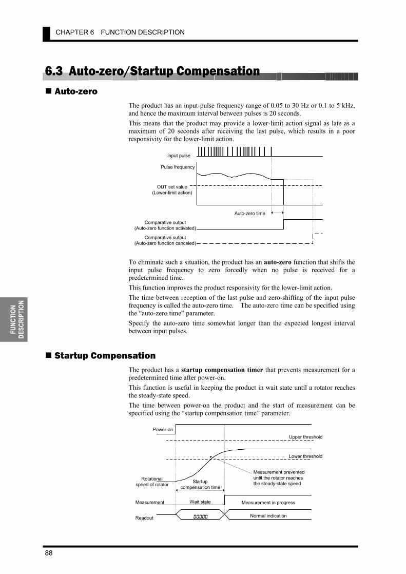
CHAPTER 6 FUNCTION DESCRIPTION
88
FUNC
TION
DE
SCRI
PTIO
N
6.3 Auto-zero/Startup Compensation Auto-zero
The product has an input-pulse frequency range of 0.05 to 30 Hz or 0.1 to 5 kHz, and hence the maximum interval between pulses is 20 seconds. This means that the product may provide a lower-limit action signal as late as a maximum of 20 seconds after receiving the last pulse, which results in a poor responsivity for the lower-limit action.
To eliminate such a situation, the product has an auto-zero function that shifts the input pulse frequency to zero forcedly when no pulse is received for a predetermined time. This function improves the product responsivity for the lower-limit action. The time between reception of the last pulse and zero-shifting of the input pulse frequency is called the auto-zero time. The auto-zero time can be specified using the “auto-zero time” parameter. Specify the auto-zero time somewhat longer than the expected longest interval between input pulses.
Startup Compensation The product has a startup compensation timer that prevents measurement for a predetermined time after power-on. This function is useful in keeping the product in wait state until a rotator reaches the steady-state speed. The time between power-on the product and the start of measurement can be specified using the “startup compensation time” parameter.
Input pulse Pulse frequency
OUT set value (Lower-limit action)
Auto-zero time Comparative output
(Auto-zero function activated) Comparative output
(Auto-zero function canceled)
Power-on Upper threshold
Lower threshold
Startup compensation time
Rotational speed of rotator
Measurement Measurement in progress
Readout 00000
Wait state
Normal indication
Measurement prevented until the rotator reaches the steady-state speed
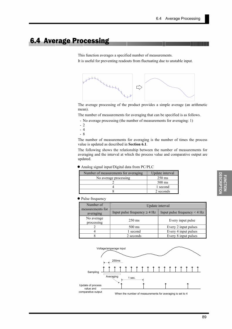
6.4 Average Processing
89
FUNCTION DESCRIPTION
6.4 Average Processing This function averages a specified number of measurements. It is useful for preventing readouts from fluctuating due to unstable input.
The average processing of the product provides a simple average (an arithmetic mean). The number of measurements for averaging that can be specified is as follows.
- No average processing (the number of measurements for averaging: 1) - 2 - 4 - 8
The number of measurements for averaging is the number of times the process value is updated as described in Section 6.1. The following shows the relationship between the number of measurements for averaging and the interval at which the process value and comparative output are updated.
Analog signal input/Digital data from PC/PLC Number of measurements for averaging Update interval
No average processing 250 ms 2 500 ms 4 1 second 8 2 seconds
Pulse frequency
Update interval Number of measurements for
averaging Input pulse frequency ≥ 4 Hz Input pulse frequency < 4 HzNo average processing 250 ms Every input pulse
2 500 ms Every 2 input pulses 4 1 second Every 4 input pulses 8 2 seconds Every 8 input pulses
Voltage/amperage input
250ms
AveragingSampling
Update of processvalue and
comparative output
1 sec.
When the number of measurements for averaging is set to 4
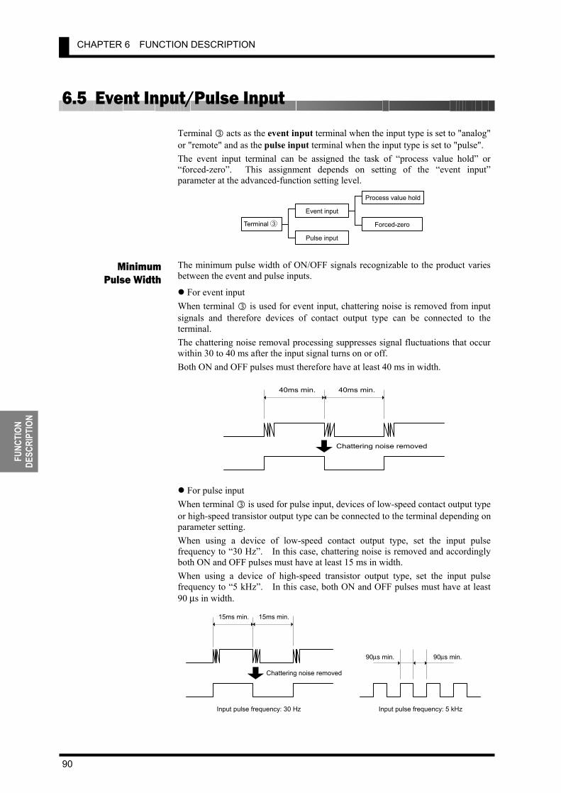
CHAPTER 6 FUNCTION DESCRIPTION
90
FUNC
TION
DE
SCRI
PTIO
N
6.5 Event Input/Pulse Input Terminal acts as the event input terminal when the input type is set to "analog" or "remote" and as the pulse input terminal when the input type is set to "pulse". The event input terminal can be assigned the task of “process value hold” or “forced-zero”. This assignment depends on setting of the “event input” parameter at the advanced-function setting level.
The minimum pulse width of ON/OFF signals recognizable to the product varies between the event and pulse inputs.
For event input When terminal is used for event input, chattering noise is removed from input signals and therefore devices of contact output type can be connected to the terminal. The chattering noise removal processing suppresses signal fluctuations that occur within 30 to 40 ms after the input signal turns on or off. Both ON and OFF pulses must therefore have at least 40 ms in width.
For pulse input
When terminal is used for pulse input, devices of low-speed contact output type or high-speed transistor output type can be connected to the terminal depending on parameter setting. When using a device of low-speed contact output type, set the input pulse frequency to “30 Hz”. In this case, chattering noise is removed and accordingly both ON and OFF pulses must have at least 15 ms in width. When using a device of high-speed transistor output type, set the input pulse frequency to “5 kHz”. In this case, both ON and OFF pulses must have at least 90 µs in width.
Minimum Pulse Width
Chattering noise removed
40ms min. 40ms min.
Terminal Event input
Pulse input
Process value hold
Forced-zero 3
Chattering noise removed
15ms min. 15ms min.
Input pulse frequency: 30 Hz
90 µ s min. 90µs min.
Input pulse frequency: 5 kHz

6.6 Process Value Hold
91
FUNCTION DESCRIPTION
6.6 Process Value Hold This function detects the process value at the instant when the event input turns on, and holds the value as long as the event input is on. It can be used to hold the process value detected when a failure occurs. “Process value hold” takes place via the event input terminal. The following illustrates the “process value hold” operation.
• When the event input (HOLD) turns on, the process value is detected and held. • If the input value changes, the process value continues to be held as long as the
event input is on. • When the event input (HOLD) turns off, the “process value hold” function is
canceled and the display returns to the current value.
The “process value hold” function is available only when the input type is set to "analog" or "remote" and terminal ③ is assigned the task of “process value hold”.
TIPS
Process value
HOLD inputThe minimum input timefor HOLD signal is 80ms.
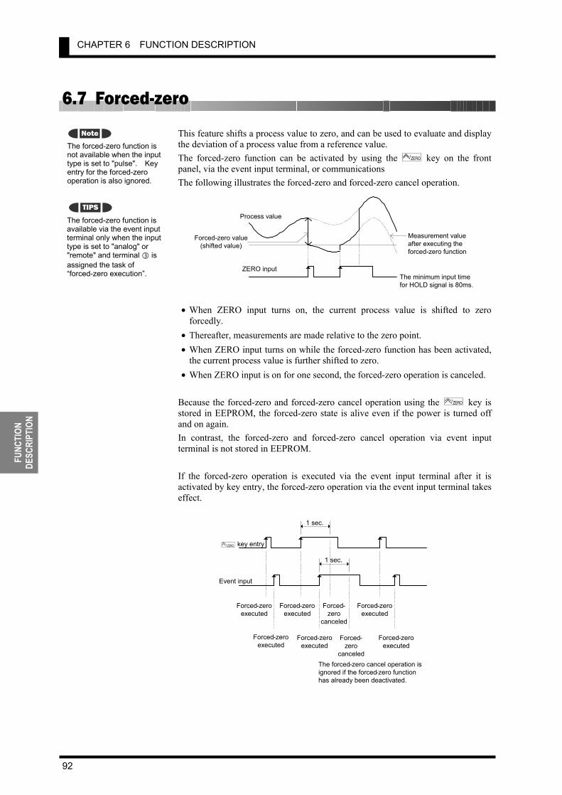
CHAPTER 6 FUNCTION DESCRIPTION
92
FUNC
TION
DE
SCRI
PTIO
N
6.7 Forced-zero This feature shifts a process value to zero, and can be used to evaluate and display the deviation of a process value from a reference value. The forced-zero function can be activated by using the
ZERO/ key on the front panel, via the event input terminal, or communications The following illustrates the forced-zero and forced-zero cancel operation.
• When ZERO input turns on, the current process value is shifted to zero
forcedly. • Thereafter, measurements are made relative to the zero point. • When ZERO input turns on while the forced-zero function has been activated,
the current process value is further shifted to zero. • When ZERO input is on for one second, the forced-zero operation is canceled.
Because the forced-zero and forced-zero cancel operation using the ZERO/ key is stored in EEPROM, the forced-zero state is alive even if the power is turned off and on again. In contrast, the forced-zero and forced-zero cancel operation via event input terminal is not stored in EEPROM. If the forced-zero operation is executed via the event input terminal after it is activated by key entry, the forced-zero operation via the event input terminal takes effect.
The forced-zero function is available via the event input terminal only when the input type is set to "analog" or "remote" and terminal is assigned the task of “forced-zero execution”.
The forced-zero function is not available when the input type is set to "pulse". Key entry for the forced-zero operation is also ignored.
Note
TIPS
1 sec.
Forced-zeroexecuted
Forced- zero
canceled
1 sec. ZERO/ key entry
Event input
The forced - zero cancel operation isignored if the forced - zero functionhas already been deactivated.
Forced-zeroexecuted
Forced - zero executed
Forced-zeroexecuted
Forced-zeroexecuted
Forced - zeroexecuted
Forced - z ero
canceled
Process value
ZERO inputThe minimum input timefor HOLD signal is 80ms.
Forced-zero value(shifted value)
Measurement valueafter executing theforced-zero function
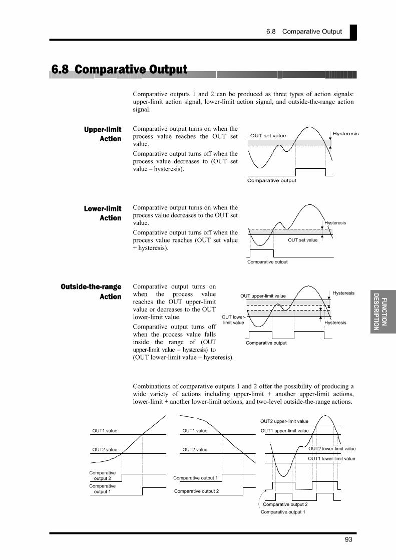
6.8 Comparative Output
93
FUNCTION DESCRIPTION
6.8 Comparative Output Comparative outputs 1 and 2 can be produced as three types of action signals: upper-limit action signal, lower-limit action signal, and outside-the-range action signal. Comparative output turns on when the process value reaches the OUT set value. Comparative output turns off when the process value decreases to (OUT set value – hysteresis). Comparative output turns on when the process value decreases to the OUT set value. Comparative output turns off when the process value reaches (OUT set value + hysteresis). Comparative output turns on when the process value reaches the OUT upper-limit value or decreases to the OUT lower-limit value. Comparative output turns off when the process value falls inside the range of (OUT upper-limit value – hysteresis) to (OUT lower-limit value + hysteresis). Combinations of comparative outputs 1 and 2 offer the possibility of producing a wide variety of actions including upper-limit + another upper-limit actions, lower-limit + another lower-limit actions, and two-level outside-the-range actions.
Upper-limitAction
Lower-limitAction
Outside-the-rangeAction
OUT set value
Comparative output
Hysteresis
OUT set value
Comparative output
Hysteresis
OUT lower- limit value
Comparative output
OUT upper-limit value Hysteresis
Hysteresis
OUT1 value
OUT2 value
Comparative output 2
Comparative output 1
OUT1 value
OUT2 value
Comparative output 2
Comparative output 1
OUT1 upper-limit value
Comparative output 2Comparative output 1
OUT2 upper-limit value
OUT2 lower-limit value
OUT1 lower-limit value
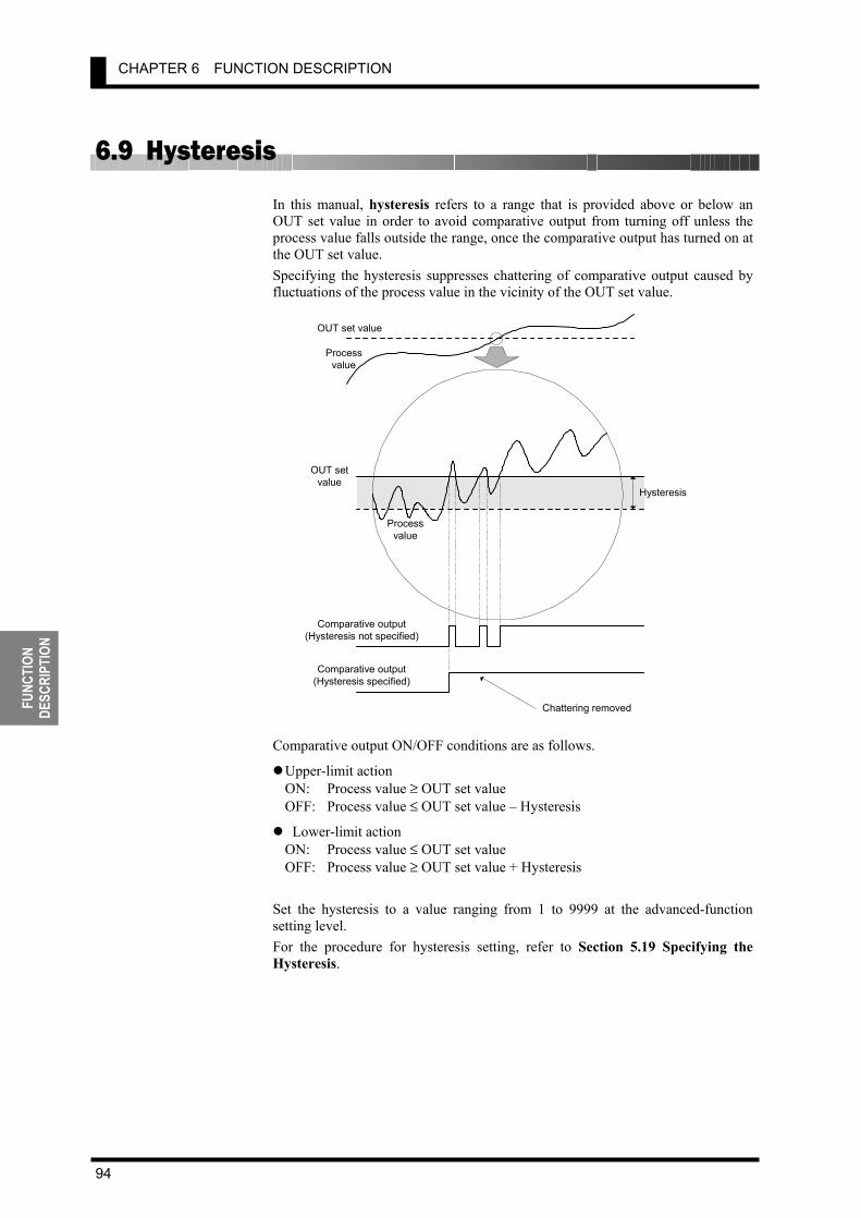
CHAPTER 6 FUNCTION DESCRIPTION
94
FUNC
TION
DE
SCRI
PTIO
N
6.9 Hysteresis In this manual, hysteresis refers to a range that is provided above or below an OUT set value in order to avoid comparative output from turning off unless the process value falls outside the range, once the comparative output has turned on at the OUT set value. Specifying the hysteresis suppresses chattering of comparative output caused by fluctuations of the process value in the vicinity of the OUT set value.
Comparative output ON/OFF conditions are as follows.
Upper-limit action ON: Process value ≥ OUT set value OFF: Process value ≤ OUT set value – Hysteresis
Lower-limit action ON: Process value ≤ OUT set value OFF: Process value ≥ OUT set value + Hysteresis
Set the hysteresis to a value ranging from 1 to 9999 at the advanced-function setting level. For the procedure for hysteresis setting, refer to Section 5.19 Specifying the Hysteresis.
OUT set value
Processvalue
OUT setvalue
Processvalue
Hysteresis
Comparative output(Hysteresis not specified)
Comparative output(Hysteresis specified)
Chattering removed

6.10 Display Color Change
95
FUNCTION DESCRIPTION
6.10 Display Color Change The display color of the main indicator can be changed. This feature can be used to vary the display color of the gang-mounted products depending on their importance or to give greater prominence to indications on the main indicator of certain products in an emergency.
Four display color change options are available. Green to red: The display color of the main indicator is green when both of
comparative outputs 1 and 2 is off, and changes to red when either of the comparative outputs turns on.
Always green: The display color is always green. Always red: The display color is always red. Red to green: The display color is red when both of comparative outputs 1 and 2
is off, and changes to green when either of the comparative outputs turns on.
Select one among these options at the advanced-function setting level. For the procedure for programming of display colors, refer to Section 5.22 Changing the Display Color.
1*0058
T
OUT2 value
OUT1 value 1!2368
T
1(7818
T
Green
Red
Red
Display color change from green to red

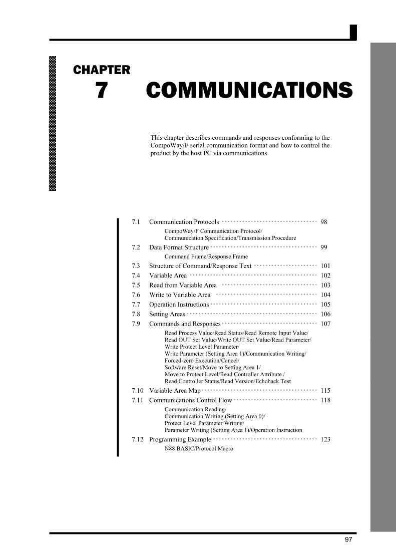
6.10 Display Color Change
97
COMMUNI- CATIONS
7 COMMUNICATIONS
7.1 Communication Protocols ・・・・・・・・・・・・・・・・・・・・・・・・・・・・・・・・・ 98 CompoWay/F Communication Protocol/ Communication Specification/Transmission Procedure
7.2 Data Format Structure ・・・・・・・・・・・・・・・・・・・・・・・・・・・・・・・・・・・・・ 99 Command Frame/Response Frame
7.3 Structure of Command/Response Text ・・・・・・・・・・・・・・・・・・・・・・ 101 7.4 Variable Area ・・・・・・・・・・・・・・・・・・・・・・・・・・・・・・・・・・・・・・・・・・・・ 102 7.5 Read from Variable Area ・・・・・・・・・・・・・・・・・・・・・・・・・・・・・・・・・ 103 7.6 Write to Variable Area ・・・・・・・・・・・・・・・・・・・・・・・・・・・・・・・・・・・ 104 7.7 Operation Instructions・・・・・・・・・・・・・・・・・・・・・・・・・・・・・・・・・・・・・ 105 7.8 Setting Areas ・・・・・・・・・・・・・・・・・・・・・・・・・・・・・・・・・・・・・・・・・・・・・ 106 7.9 Commands and Responses・・・・・・・・・・・・・・・・・・・・・・・・・・・・・・・・・ 107
Read Process Value/Read Status/Read Remote Input Value/ Read OUT Set Value/Write OUT Set Value/Read Parameter/ Write Protect Level Parameter/ Write Parameter (Setting Area 1)/Communication Writing/ Forced-zero Execution/Cancel/ Software Reset/Move to Setting Area 1/ Move to Protect Level/Read Controller Attribute / Read Controller Status/Read Version/Echoback Test
7.10 Variable Area Map・・・・・・・・・・・・・・・・・・・・・・・・・・・・・・・・・・・・・・・・ 115 7.11 Communications Control Flow ・・・・・・・・・・・・・・・・・・・・・・・・・・・・・ 118
Communication Reading/ Communication Writing (Setting Area 0)/ Protect Level Parameter Writing/ Parameter Writing (Setting Area 1)/Operation Instruction
7.12 Programming Example ・・・・・・・・・・・・・・・・・・・・・・・・・・・・・・・・・・・・ 123 N88 BASIC/Protocol Macro
This chapter describes commands and responses conforming to theCompoWay/F serial communication format and how to control the product by the host PC via communications.
CHAPTER
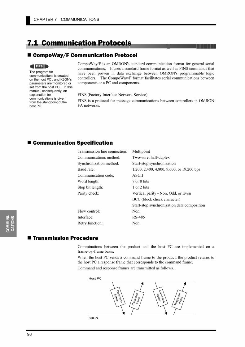
CHAPTER 7 COMMUNICATIONS
98
COMM
UNI-
CATI
ONS
7.1 Communication Protocols CompoWay/F Communication Protocol
CompoWay/F is an OMRON's standard communication format for general serial communications. It uses a standard frame format as well as FINS commands that have been proven in data exchange between OMRON's programmable logic controllers. The CompoWay/F format facilitates serial communications between components or a PC and components. FINS (Factory Interface Network Service) FINS is a protocol for message communications between controllers in OMRON FA networks.
Communication Specification Transmission line connection: Multipoint Communications method: Two-wire, half-duplex Synchronization method: Start-stop synchronization Baud rate: 1,200, 2,400, 4,800, 9,600, or 19.200 bps Communication code: ASCII Word length: 7 or 8 bits Stop bit length: 1 or 2 bits Parity check: Vertical parity - Non, Odd, or Even BCC (block check character) Start-stop synchronization data composition Flow control: Non Interface: RS-485 Retry function: Non
Transmission Procedure Comminations between the product and the host PC are implemented on a frame-by-frame basis. When the host PC sends a command frame to the product, the product returns to the host PC a response frame that corresponds to the command frame. Command and response frames are transmitted as follows.
The program for communications is created on the host PC , and K3GN's parameters are monitored or set from the host PC. In this manual, consequently, an explanation for communications is given from the standpoint of the host PC.
TIPS
K3GN
Host PC
Com
mand
frame
Res
pons
efra
me
Com
mand
frame
Res
pons
efra
me

7.2 Data Format Structure
99
COMMUNI- CATIONS
7.2 Data Format Structure Comminations conforming to the CompoWay/F serial communication format involve transmission of blocks of data that are called frames. Those sent from the host PC are command frames and those from the product are response frames. The structure of these frames is shown below. In the following frame description, suffix H added to a numeric value, as in 02H, means the value is a hexadecimal number. And double quotation marks in which an alphanumeric value is enclosed, as in “00”, mean that the value is an ASCII character set. The number underneath each delimiter in a frame indicates the number of bytes.
Command Frame
STX Code indicating the start of a command frame (02H). Be sure to place this code in the first byte of a command frame.
Node No
Node ID specifying the destination of a command frame. Set this No. to the “unit No.” of the product. If you want to broadcast a command, set this No. to “XX”. Note that, in this case, no response is given from the products.
Sub-address Not used for K3GN. Always set the sub-address to “00”. SID
(Service ID) Not used for K3GN. Always set the SID to “0”.
Command text Command text ETX Code indicating the end of text (03H)
BCC Block check character. The result of block check on the BCC calculation range is stored in this filed.
How to determine BCC: BCC is determined by XOR operation, on a byte-by-byte basis, of the values within the range from the Node No. field to the ETX field. The result (36H in the example shown right) is placed in the BCC field.
TIPS
STX
02H
Node No. Sub-address "00"
SID
"0"
Command text ETX
03H
BCC
1 2 2 1 1 1 byte
BCC calculation range
STX
02H
Node No. 30H 30H
Sub-address 30H 30H
SID
30H
Command text 30H 35H 30H 30H
ETX
03H
BCC
36H
30H 30H 30H 30H 30H 30H 35H 30H 03H = 36HBCC = 30H : XOR (exclusive OR) operation
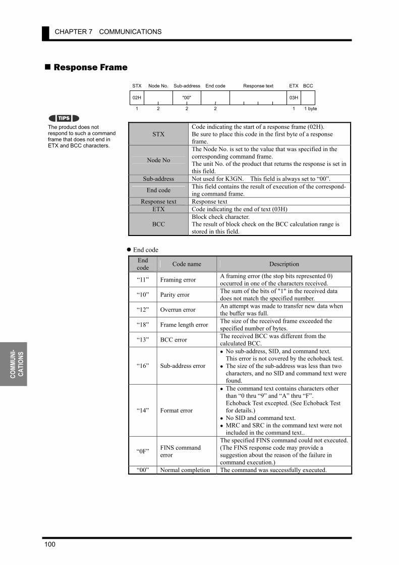
CHAPTER 7 COMMUNICATIONS
100
COMM
UNI-
CATI
ONS
Response Frame
STX Code indicating the start of a response frame (02H). Be sure to place this code in the first byte of a response frame.
Node No
The Node No. is set to the value that was specified in the corresponding command frame. The unit No. of the product that returns the response is set in this field.
Sub-address Not used for K3GN. This field is always set to “00”.
End code This field contains the result of execution of the correspond-ing command frame.
Response text Response text ETX Code indicating the end of text (03H)
BCC Block check character. The result of block check on the BCC calculation range is stored in this field.
End code
End code Code name Description
“11” Framing error A framing error (the stop bits represented 0) occurred in one of the characters received.
“10” Parity error The sum of the bits of "1" in the received data does not match the specified number.
“12” Overrun error An attempt was made to transfer new data when the buffer was full.
“18” Frame length error The size of the received frame exceeded the specified number of bytes.
“13” BCC error The received BCC was different from the calculated BCC.
“16” Sub-address error
• No sub-address, SID, and command text. This error is not covered by the echoback test.
• The size of the sub-address was less than two characters, and no SID and command text were found.
“14” Format error
• The command text contains characters other than “0 thru “9” and “A” thru “F”. Echoback Test excepted. (See Echoback Test for details.)
• No SID and command text. • MRC and SRC in the command text were not
included in the command text..
“0F” FINS command error
The specified FINS command could not executed.(The FINS response code may provide a suggestion about the reason of the failure in command execution.)
“00” Normal completion The command was successfully executed.
The product does not respond to such a command frame that does not end in ETX and BCC characters.
TIPS
STX
02H
Node No. Sub-address
"00"
Response text ETX
03H
BCC
1 2 2 1 1 byte
End code
2
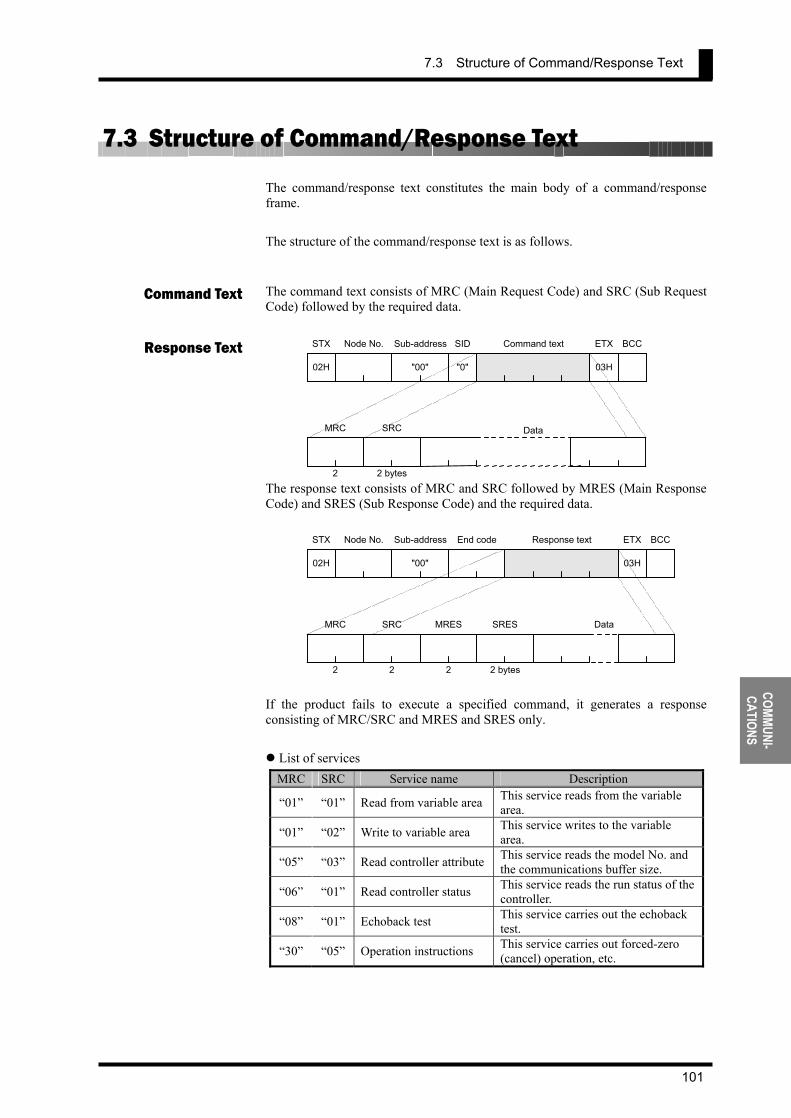
7.3 Structure of Command/Response Text
101
COMMUNI- CATIONS
7.3 Structure of Command/Response Text The command/response text constitutes the main body of a command/response frame. The structure of the command/response text is as follows. The command text consists of MRC (Main Request Code) and SRC (Sub Request Code) followed by the required data.
The response text consists of MRC and SRC followed by MRES (Main Response Code) and SRES (Sub Response Code) and the required data.
If the product fails to execute a specified command, it generates a response consisting of MRC/SRC and MRES and SRES only.
List of services MRC SRC Service name Description
“01” “01” Read from variable area This service reads from the variable area.
“01” “02” Write to variable area This service writes to the variable area.
“05” “03” Read controller attribute This service reads the model No. and the communications buffer size.
“06” “01” Read controller status This service reads the run status of the controller.
“08” “01” Echoback test This service carries out the echoback test.
“30” “05” Operation instructions This service carries out forced-zero (cancel) operation, etc.
Command Text
Response Text
MRC
2
SRC
2 bytes
Data
STX
02H
Node No. Sub-address
"00"
SID
"0"
Command text ETX
03H
BCC
STX
02H
Node No. Sub-address
"00"
Response text ETX
03H
BCCEnd code
MRC
2
SRC
2
MRES
2
SRES
2 bytes
Data
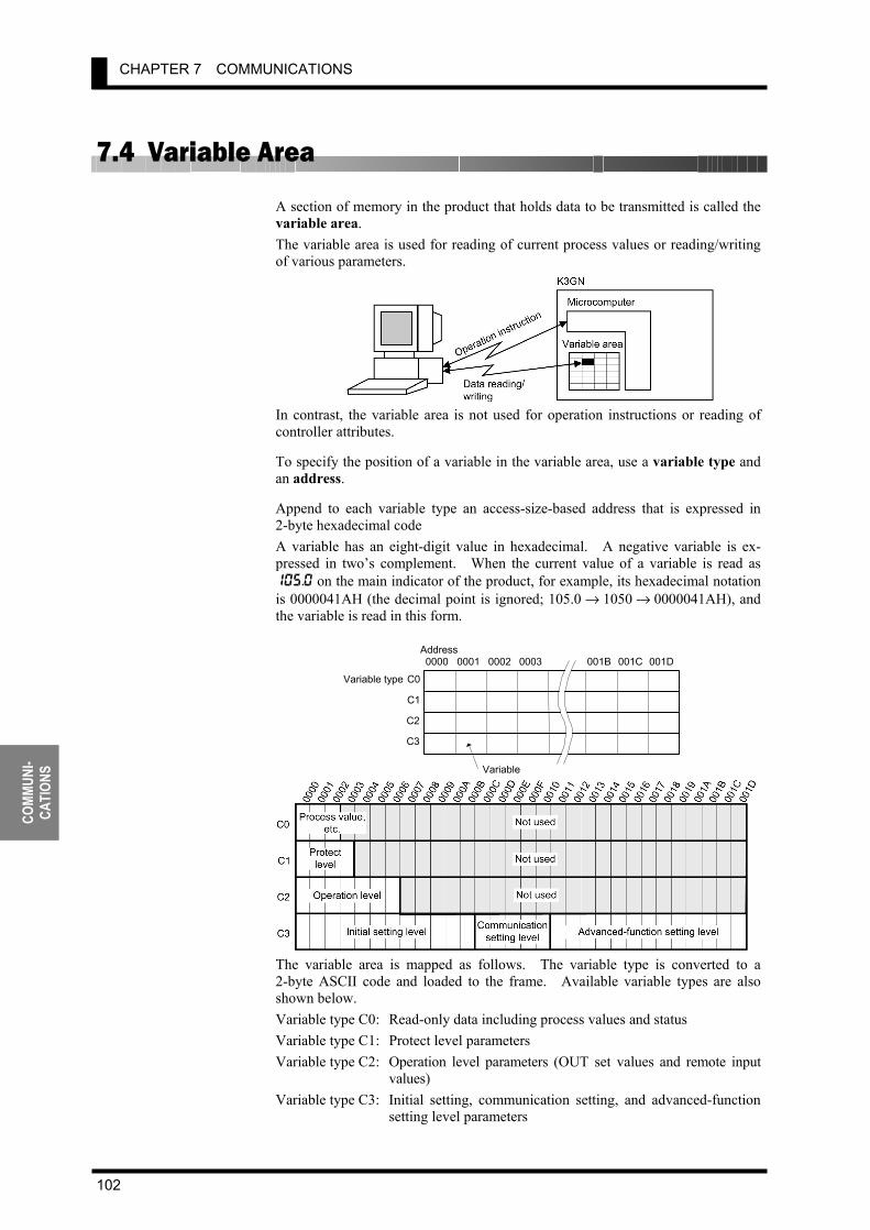
CHAPTER 7 COMMUNICATIONS
102
COMM
UNI-
CATI
ONS
7.4 Variable Area A section of memory in the product that holds data to be transmitted is called the variable area. The variable area is used for reading of current process values or reading/writing of various parameters.
In contrast, the variable area is not used for operation instructions or reading of controller attributes.
To specify the position of a variable in the variable area, use a variable type and an address.
Append to each variable type an access-size-based address that is expressed in 2-byte hexadecimal code A variable has an eight-digit value in hexadecimal. A negative variable is ex-pressed in two’s complement. When the current value of a variable is read as 105.0 on the main indicator of the product, for example, its hexadecimal notation is 0000041AH (the decimal point is ignored; 105.0 → 1050 → 0000041AH), and the variable is read in this form.
The variable area is mapped as follows. The variable type is converted to a 2-byte ASCII code and loaded to the frame. Available variable types are also shown below. Variable type C0: Read-only data including process values and status Variable type C1: Protect level parameters Variable type C2: Operation level parameters (OUT set values and remote input
values) Variable type C3: Initial setting, communication setting, and advanced-function
setting level parameters
0000 0001 0002 0003 001B 001C 001DAddress
C0
C1
C2
C3
Variable type
Variable

7.5 Read from Variable Area
103
COMMUNI- CATIONS
7.5 Read from Variable Area This service reads data from the variable areas. Command text
Item Description
MRC/SRC Set these items to “01"/"01” ("Read from Variable Area" service).
Variable type Set this item to one among “C0” thru “C3”. Read start address Specify the read start address at this field. Bit position Not used for K3GN. Always set this item to “00”.
No. of elements Set this item to the quantity of variables that are to be read (up to 10).
Response text
Item Description
MRC/SRC This field contains the same value (“01"/"01”) as specified in the command text.
Response code This field contains the result of execution of the command. Data to be read This field contains the data that is read and to be read.
Response codes
Response code Code name Description
“1001” Command length over The command is too long. “1002” Command length short The command is too short. “1101” Area type error The specified variable type is invalid.
“1103” Start address out-of-range error
The specified start address is outside the valid range.
“110B” Response length over The No. of elements exceeds 10.
“1100” Parameter error The bit position is set to a value other than “00”.
“2203” Operation error EEPROM error “0000” Normal completion The command was successfully executed.
Command
Response MRC
"01"
2
SRC
2
"01"
Response code(MRES/SRES)
4
Data to be read
(No. of elements x 8) bytes
MRC
"01"
2
SRC
2
"01"
Variabletype
2
Read startaddress
4
Bit position
2
"00" No. of elements
4 bytes
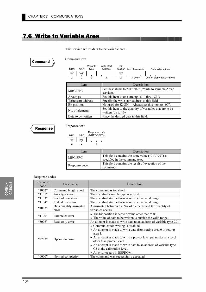
CHAPTER 7 COMMUNICATIONS
104
COMM
UNI-
CATI
ONS
7.6 Write to Variable Area This service writes data to the variable area. Command text
Item Description
MRC/SRC Set these items to “01”/“02” ("Write to Variable Area" service).
Area type Set this item to one among “C1” thru “C3”. Write start address Specify the write start address at this field. Bit position Not used for K3GN. Always set this item to “00”.
No. of elements Set this item to the quantity of variables that are to be written (up to 10).
Data to be written Place the desired data in this field. Response text
Item Description
MRC/SRC This field contains the same value (“01”/“02”) as specified in the command text.
Response code This field contains the result of execution of the command.
Response codes
Response code Code name Description
“1002” Command length short The command is too short. “1101” Area type error The specified variable type is invalid. “1103” Start address error The specified start address is outside the valid range. “1104” End address error The specified start address is outside the valid range.
“1003” Data quantity mismatch error
A mismatch between the No. of elements and the quantity of variables occurs.
“1100” Parameter error • The bit position is set to a value other than “00”. • The value of data to be written is outside the valid range.
“3003” Read only error An attempt is made to write data to an address of variable type C0.
“2203” Operation error
• Communication writing is disabled. • An attempt is made to write data from setting area 0 to setting
area 1. • An attempt is made to write a protect level parameter at a level
other than protect level. • An attempt is made to write data to an address of variable type
C3 at the calibration level. • An error occurs in EEPROM.
“0000” Normal completion The command was successfully executed.
Command
Response MRC
"01"
2
SRC
2
"02"
Response code(MRES/SRES)
4
MRC
"01"
2
SRC
2
"02"
Variabletype
2
Write startaddress
4
Bitposition
2
"00"
Data to be written
(No. of elements x 8) bytes
No. of elements
4 bytes

7.7 Operation Instructions
105
COMMUNI- CATIONS
7.7 Operation Instructions To issue an operation instruction to the product, set the items in the command text as follows. Command text
Item Description MRC/SRC Set these item to “30”/”05” (Operation Instruction service). Instruction code Place an instruction code in this field.
Related information Place information related to the operation instruction in this field.
Instruction codes
Instruction code Operation Related information
“00”: Off (disable) “00” Communication writing“01”: On (enable) “00”: Cancel
“03” Forced-forced-zero execution/ Forced-zero cancel
“01”: Execute
“06” Software reset “00” “07” Move to setting area 1 “00” “08” Move to protect level “00”
Response text
Item Description
MRC/SRC This field contains the same value (“30”/"05") as specified in the command text.
Response code This field contains the result of execution of the command. Response codes
Response code Code name Description
“1001” Command length over The command is too long. “1002” Command length short The command is too short.
“1100” Parameter error The instruction code or related information is invalid.
“2203” Operation error
• Communication writing is disabled. • The specified operation cannot be
executed. For details, refer to Section 7.9 Commands and Responses.
• An error occurs in EEPROM. “0000” Normal completion The command was successfully executed.
Command
Response
MRC
"30"
2
SRC
2
"05"
Instructioncode
2
Relatedinformation
2 bytes
MRC
"30"
2
SRC
2
"05"
Response code(MRES/SRES)
4 bytes
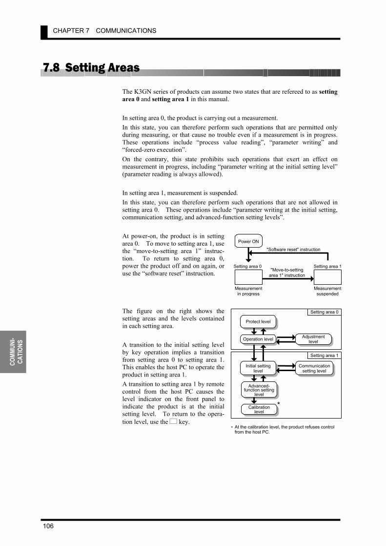
CHAPTER 7 COMMUNICATIONS
106
COMM
UNI-
CATI
ONS
7.8 Setting Areas The K3GN series of products can assume two states that are refereed to as setting area 0 and setting area 1 in this manual. In setting area 0, the product is carrying out a measurement. In this state, you can therefore perform such operations that are permitted only during measuring, or that cause no trouble even if a measurement is in progress. These operations include “process value reading”, “parameter writing” and “forced-zero execution”. On the contrary, this state prohibits such operations that exert an effect on measurement in progress, including “parameter writing at the initial setting level” (parameter reading is always allowed). In setting area 1, measurement is suspended. In this state, you can therefore perform such operations that are not allowed in setting area 0. These operations include “parameter writing at the initial setting, communication setting, and advanced-function setting levels”. At power-on, the product is in setting area 0. To move to setting area 1, use the “move-to-setting area 1” instruc-tion. To return to setting area 0, power the product off and on again, or use the “software reset” instruction. The figure on the right shows the setting areas and the levels contained in each setting area. A transition to the initial setting level by key operation implies a transition from setting area 0 to setting area 1. This enables the host PC to operate the product in setting area 1. A transition to setting area 1 by remote control from the host PC causes the level indicator on the front panel to indicate the product is at the initial setting level. To return to the opera-tion level, use the L key.
Setting area 0 Setting area 1
Power ON
"Move-to-setting area 1" instruction
"Software reset" instruction
Measurement in progress
Measurementsuspended
Protect level
Adjustment level
Calibration level
Setting area 0
Setting area 1
Operation level
Initial setting level Communication
setting level
Advanced- function setting
level *
* At the calibration level, the product refuses control from the host PC.

7.9 Commands and Responses
107
COMMUNI- CATIONS
7.9 Commands and Responses Various commands for application layer are available for implementing the services, such as “variable area read/write” and “operation instructions”, offered by the CompoWay/F communication format. This section contains description of the available commands for the application layer.
Read Process Value This command reads the current process value. Use this command when the product is in setting area 0. (If the product is in setting area 1 when receiving the command, it returns a response with the “unknown” current value data).
Response code: The code shown above represents normal completion. For details on the response code, refer to Section 7.5 Read from Variable Area .
Read Status This command reads the status of comparative outputs or the like. Use this command when the product is in setting area 0. (If the product is in setting area 1 when receiving the command, it returns a response with the “unknown” status data).
For details on the status, refer to Section 7.10 Variable Area Map. Response code: The code shown above represents normal completion. For details on the response code, refer to Section 7.5 Read from Variable Area .
Command
Response
Command
Response
Process value
MRC
"01"
SRC
"01" "0000"
Response code Data
Status
MRC
"01"
SRC
"01" "0000"
Response code Data
MRC
"01"
SRC
"01"
Variabletype
"C0" "0001"
AddressBit
position "00" "0001"
No. of elements
MRC
"01"
SRC
"01"
Variabletype
"C0" "0002"
AddressBit
position "00" "0001"
No. of elements
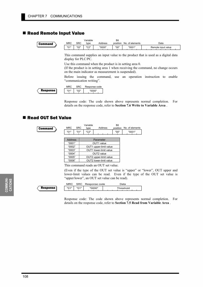
CHAPTER 7 COMMUNICATIONS
108
COMM
UNI-
CATI
ONS
Read Remote Input Value This command supplies an input value to the product that is used as a digital data display for PLC/PC. Use this command when the product is in setting area 0. (If the product is in setting area 1 when receiving the command, no change occurs on the main indicator as measurement is suspended). Before issuing the command, use an operation instruction to enable “communication writing”.
Response code: The code shown above represents normal completion. For details on the response code, refer to Section 7.6 Write to Variable Area .
Read OUT Set Value
Address Parameter “0001” OUT1 value “0002” OUT1 upper-limit value “0003” OUT1 lower-limit value “0004” OUT2 value “0005” OUT2 upper-limit value “0006” OUT2 lower-limit value
This command reads an OUT set value. (Even if the type of the OUT set value is “upper” or “lower”, OUT upper and lower-limit values can be read. Even if the type of the OUT set value is “upper/lower”, an OUT set value can be read).
Response code: The code shown above represents normal completion. For details on the response code, refer to Section 7.5 Read from Variable Area .
Command
Response
Command
Response Threshold
MRC
"01"
SRC
"01" "0000"
Response code Data
MRC
"01"
SRC
"02"
Variabletype
"C2" "0000"
AddressBit
position
"00" "0001" No. of elements
Remote input value
Data
MRC
"01"
SRC
"02" "0000"
Response code
MRC
"01"
SRC
"01"
Variabletype"C2"
AddressBit
position"00" "0001"
No. of elements
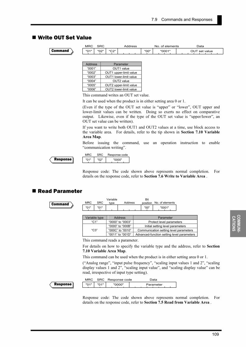
7.9 Commands and Responses
109
COMMUNI- CATIONS
Write OUT Set Value
Address Parameter “0001” OUT1 value “0002” OUT1 upper-limit value “0003” OUT1 lower-limit value “0004” OUT2 value “0005” OUT2 upper-limit value “0006” OUT2 lower-limit value
This command writes an OUT set value. It can be used when the product is in either setting area 0 or 1. (Even if the type of the OUT set value is “upper” or “lower”, OUT upper and lower-limit values can be written. Doing so exerts no effect on comparative output. Likewise, even if the type of the OUT set value is “upper/lower”, an OUT set value can be written). If you want to write both OUT1 and OUT2 values at a time, use block access to the variable area. For details, refer to the tip shown in Section 7.10 Variable Area Map. Before issuing the command, use an operation instruction to enable “communication writing”.
Response code: The code shown above represents normal completion. For details on the response code, refer to Section 7.6 Write to Variable Area .
Read Parameter
Variable type Address Parameter “C1” “0000” to “0003” Protect level parameters
“0000” to “000B” Initial setting level parameters “000C” to “0010” Communication setting level parameters “C3” “0011” to “001D” Advanced-function setting level parameters
This command reads a parameter. For details on how to specify the variable type and the address, refer to Section 7.10 Variable Area Map. This command can be used when the product is in either setting area 0 or 1. (“Analog range”, “input pulse frequency”, “scaling input values 1 and 2”, “scaling display values 1 and 2”, “scaling input value”, and “scaling display value” can be read, irrespective of input type setting).
Response code: The code shown above represents normal completion. For details on the response code, refer to Section 7.5 Read from Variable Area .
Command
Response
Command
Response Parameter
MRC
"01"
SRC
"01" "0000"
Response code Data
MRC
"01"
SRC
"02" "C2"
Address
"00" "0001"
No. of elements
OUT set value
Data
MRC
"01"
SRC
"02" "0000"
Response code
MRC
"01"
SRC
"01"
Variabletype Address
Bitposition
"00" "0001" No. of elements

CHAPTER 7 COMMUNICATIONS
110
COMM
UNI-
CATI
ONS
Write Protect Level Parameter
Address Parameter “0000” Operation/adjustment lockouts “0001” Initial setting/communication lockouts“0002” Setting change lockout “0003” Forced-zero lockout
This command writes a protect level parameter. Use this command when the product is in setting area 0. If the product is in setting area 1 when receiving the command, it returns an error. Before issuing the command, use operation instructions to enable “writing” and to enter the protect level.
Response code: The code shown above represents normal completion. For details on the response code, refer to Section 7.6 Write to Variable Area .
Write Parameter (Setting Area 1)
Address Parameter “0000” to “000B” Initial setting level parameters “000C” to “0010” Communication setting level parameters “0011” to “001D” Advanced-function setting level parameters
This command writes an initial setting level parameter, a communication setting level parameter, or an advanced-function setting level parameter. For detains on addressing, refer to Section 7.10 Variable Area Map. Use this command when the product is in setting area 1. If the product is in setting area 0 when receiving the command, it returns an error. Before issuing the command, use operation instructions to enable “communication writing” and to enter setting area 1.
Response code: The code shown above represents normal completion. For details on the response code, refer to Section 7.6 Write to Variable Area .
Command
Response
Command
Response
MRC
"01"
SRC
"02"
Variabletype
"C1"
AddressBit
position
"00" "0001"
No. of elements
Protect level parameter
Data
MRC
"01"
SRC
"02" "0000"
Response code
MRC
"01"
SRC
"02"
Variabletype
"C3"
AddressBit
position"00" "0001"
No. of elements Parameter (setting area 1)
Data
MRC
"01"
SRC
"02" "0000"
Response code

7.9 Commands and Responses
111
COMMUNI- CATIONS
Communication Writing
Related information Description “00” Communication writing disable “01” Communication writing enable
This command enables/disables communication writing. It rewrites the value of the adjustment level parameter “communication writing”. If communication writing is disabled, operation instructions for parameter rewriting, forced-zero execution/forced-zero cancel and the like are rejected. This command can be used when the product is in either setting area 0 or 1.
Response code: The code shown above represents normal completion. For details on the response code, refer to Section 7.7 Operation Instructions.
Forced-zero Execution/Cancel
Forced-zero Description “00” Forced-zero cancel “01” Forced-forced-zero execution
This command executes/cancels the forced-zero operation. Use this command when the product is in setting area 0. If product is in setting area 1 when receiving the command, it returns an error. If the product has no measured value, suffers input anomalies, or encounters a “display range over” error when receiving the command, it returns an error. If the event input is used for “process value hold” when receiving the command, it also returns an error. Before issuing the command, use an operation instruction to enable “communication writing”.
Response code: The code shown above represents normal completion. For details on the response code, refer to Section 7.7 Operation Instructions.
Command
Response
Command
Response
MRC
"30"
SRC
"05"
Instructioncode
"00"
Relatedinformation
MRC
"30"
SRC
"05" "0000"
Response code
MRC
"30"
SRC
"05"
Instructioncode
"03"
Relatedinformation
MRC
"30"
SRC
"05" "0000"
Response code
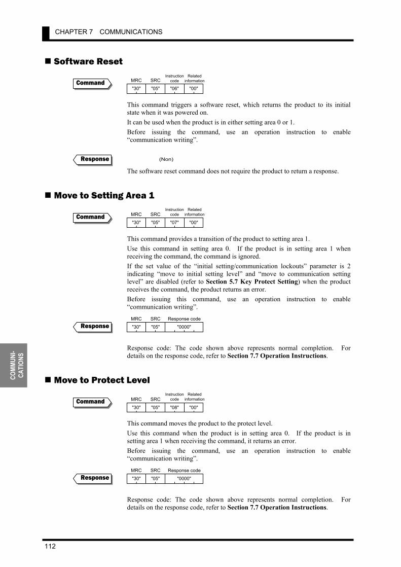
CHAPTER 7 COMMUNICATIONS
112
COMM
UNI-
CATI
ONS
Software Reset This command triggers a software reset, which returns the product to its initial state when it was powered on. It can be used when the product is in either setting area 0 or 1. Before issuing the command, use an operation instruction to enable “communication writing”.
The software reset command does not require the product to return a response.
Move to Setting Area 1 This command provides a transition of the product to setting area 1. Use this command in setting area 0. If the product is in setting area 1 when receiving the command, the command is ignored. If the set value of the “initial setting/communication lockouts” parameter is 2 indicating “move to initial setting level” and “move to communication setting level” are disabled (refer to Section 5.7 Key Protect Setting) when the product receives the command, the product returns an error. Before issuing this command, use an operation instruction to enable “communication writing”.
Response code: The code shown above represents normal completion. For details on the response code, refer to Section 7.7 Operation Instructions.
Move to Protect Level This command moves the product to the protect level. Use this command when the product is in setting area 0. If the product is in setting area 1 when receiving the command, it returns an error. Before issuing the command, use an operation instruction to enable “communication writing”.
Response code: The code shown above represents normal completion. For details on the response code, refer to Section 7.7 Operation Instructions.
Command
Response
Command
Response
Command
Response
(Non)
MRC
"30"
SRC
"05"
Instructioncode
"06"
Relatedinformation
"00"
MRC
"30"
SRC
"05"
Instructioncode
"07"
Relatedinformation
"00"
MRC
"30"
SRC
"05" "0000"
Response code
MRC
"30"
SRC
"05"
Instructioncode
"08"
Relatedinformation
"00"
MRC
"30"
SRC
"05" "0000"
Response code

7.9 Commands and Responses
113
COMMUNI- CATIONS
Read Controller Attribute This command reads the model name and communication buffer size of the product. For addressing, refer to Section 7.10 Variable Area Map. The command can be used, irrespective of what state the product is in.
Model name Buffer size Input type Output type No. of
contacts Optional feature
“K3GN-NDC” 48 × 24 NPN transistor Relay 2 Communication“K3GN-PDC” 48 × 24 PNP transistor Relay 2 Communication“K3GN-NDT1” 48 × 24 NPN transistor NPN transistor 3 Communication“K3GN-PDT2” 48 × 24 PNP transistor PNP transistor 3 Communication
The model name is expressed in 10-byte ASCII code. If the model name length is less than 10 bytes, blanks are used for padding in the model name field. A fixed value of “0068H” (104 bytes) in buffer size is returned. Response code
Response code Error name Description “1001” Command length over The command is too long. “2203” Operation error An error occurs in EEPROM. “0000” Normal completion The command is successfully executed.
Read Controller Status This command reads the operation status of the product. The command can be used, irrespective of what state the product is in.
Operation status Description “00” Measurement is in progress normally.
“01” • Measurement is suspended. • The product has no measured value, suffers input
anomalies, or encounters a “display range over” error. Related information
If the product is in setting area 1 when receiving the command, it returns a response with the “unknown” related information.
Command
Response
Command
Response
MRC
"05"
SRC
"03"
MRC
"06"
SRC
"01"
MRC
"05"
SRC
"03"
Response code Model name
"0068"
Buffer size
00 0 0 0
01234567 Bit position
No measured value Display range over
Input anomaly
Not detected Detected
Not detected Detected
Not detected Detected
Status 0 1
Value of bit
MRC
"06"
SRC
"01"
Response codeOperation
statusRelated
information

CHAPTER 7 COMMUNICATIONS
114
COMM
UNI-
CATI
ONS
Response code Response code Error name Description
“1001” Command length over The command is too long. “2203” Operation error An error occurs in EEPROM. “0000” Normal completion The command is successfully executed.
Read Version This command reads the product software version. The command can be used, irrespective of the state of the product.
Response code: The code shown above represents normal completion. For details on the response code, refer to Section 7.5 Read from Variable Area .
Echoback Test This command performs an echoback test. The command can be used, irrespective of the state of the product. Data to be checked must not exceed communication data in length.
Communication data length Description 7 bits 20H to 7EH converted to ASCII code 8 bits 20H to 7EH or A1H to FEH converted to ASCII code
Response code
Response code Error name Description “1001” Command length over The command is too long. “2203” Operation error An error occurs in EEPROM. “0000” Normal completion The command is successfully executed.
Command
Response
Command
Response
Version No.
MRC
"01"
SRC
"01" "0000"
Response code Data
MRC
"01"
SRC
"01"
Variabletype
"C0" "0000"
AddressBit
position
"00" "0001" No. of elements
MRC
"08"
SRC
"01"
Data to be tested0 to 87 bytes
MRC"08"
SRC"01"
Response code Data to be tested 0 to 87 bytes
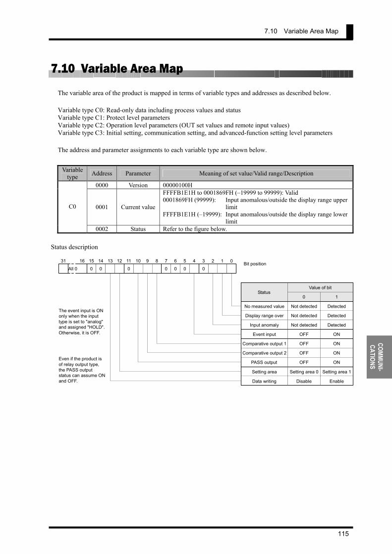
7.10 Variable Area Map
115
COMMUNI- CATIONS
7.10 Variable Area Map
The variable area of the product is mapped in terms of variable types and addresses as described below. Variable type C0: Read-only data including process values and status Variable type C1: Protect level parameters Variable type C2: Operation level parameters (OUT set values and remote input values) Variable type C3: Initial setting, communication setting, and advanced-function setting level parameters The address and parameter assignments to each variable type are shown below.
Variable
type Address Parameter Meaning of set value/Valid range/Description
0000 Version 00000100H
0001 Current value
FFFFB1E1H to 0001869FH (–19999 to 99999): Valid 0001869FH (99999): Input anomalous/outside the display range upper
limit FFFFB1E1H (–19999): Input anomalous/outside the display range lower
limit
C0
0002 Status Refer to the figure below. Status description
0 0 0 0 0 0 0
012345678910111213 14 15 16 31 All 0 Bit position
The event input is ON only when the input type is set to "analog" and assigned "HOLD". Otherwise, it is OFF.
Even if the product is of relay output type, the PASS output status can assume ON and OFF.
No measured value Display range over
Input anomaly Event input
Comparative output 1 Comparative output 2
PASS output Setting area Data writing
Not detected Detected Not detected Detected Not detected Detected
OFF ON
OFF ON
OFF ON
OFF ON
Setting area 0 Setting area 1
Disable Enable
Status 0 1
Value of bit

CHAPTER 7 COMMUNICATIONS
116
COMM
UNI-
CATI
ONS
Variable
type Address Parameter Meaning of set value/Valid range/Description
0000 Operation/ adjustment lockouts
00000000H (0): No restriction at the operation/adjustment levels 00000001H (1): “Move to adjustment level” is disabled. 00000002H (2): Only the process value can be displayed. Access via communications is enabled, irrespective of the value of this parameter.
0001 Initial setting/
communication lockouts
00000000H (0): “Move to initial setting/communication setting/advanced-function setting levels” is enabled.
00000001H (1): “Move to advanced-function setting level” is disabled.
00000002H (2): “Move to initial setting/communication setting levels” is disabled.
Access via communications is enabled, irrespective of the value of this parameter.
0002 Setting change lockout
00000000H (0): OFF: A parameter change by key operation is enabled.
00000001H (1): ON: A parameter change by key operation is disabled.
Communication writing is enabled, irrespective of the value of this parameter.
C1
0003 Forced-zero lockout
00000000H (0): OFF: Forced-zero execution/forced-zero cancel is enabled.
00000001H (1): ON: Forced-zero execution/forced-zero cancel is disabled.
Communication writing is enabled, irrespective of the value of this parameter.
0000 Remote input value
FFFFB1E1H to 0001869FH (–19999 to 99999) An input value is written to this variable when the product is used as a digital data display for PLC/PC.
0001 OUT1 value FFFFB1E1H to 0001869FH (–19999 to 99999)
0002 OUT1 upper-limit value
FFFFB1E1H to 0001869FH (–19999 to 99999)
0003 OUT1 lower-limit value
FFFFB1E1H to 0001869FH (–19999 to 99999)
0004 OUT2 value FFFFB1E1H to 0001869FH (–19999 to 99999)
0005 OUT2 upper-limit value
FFFFB1E1H to 0001869FH (–19999 to 99999)
C2
0006 OUT2 lower-limit value
FFFFB1E1H to 0001869FH (–19999 to 99999)
Variable
type Address Parameter Meaning of set value/Valid range/Description
0000 Input type 00000000H (0): Analog 00000001H (1): Pulse 00000002H (2): Remote
0001 Analog range
00000000H (0): 4 to 20 mA/0 to 20 mA 00000001H (1): 1 to 5 V/0 to 5 V 00000002H (2): ±5 V 00000003H (3): ±10 V
0002 Input pulse frequency 00000000H (0): 30 Hz 00000001H (1): 5 kHz
0003 Scaling input value 1 FFFFB1E1H to 0001869FH (–19999 to 99999) 0004 Scaling display value 1 FFFFB1E1H to 0001869FH (–19999 to 99999) 0005 Scaling input value 2 FFFFB1E1H to 0001869FH (–19999 to 99999) 0006 Scaling display value 2 FFFFB1E1H to 0001869FH (–19999 to 99999)
0007 Scaling input value FFFFB1E1H to 0001869FH (–19999 to 99999): When the input type is set to "pulse"
C3
0008 Scaling display value FFFFB1E1H to 0001869FH (–19999 to 99999): When the input type is set to "pulse"
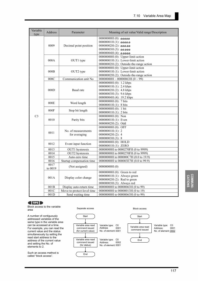
7.10 Variable Area Map
117
COMMUNI- CATIONS
Variable type Address Parameter Meaning of set value/Valid range/Description
0009 Decimal point position
00000000H (0): ,,,,, 00000001H (1): ,,,,., 00000002H (2): ,,,.,, 00000003H (3): ,,.,,, 00000004H (4): ,.,,,,
000A OUT1 type 00000000H (0): Upper-limit action 00000001H (1): Lower-limit action 00000002H (2): Outside-the-range action
000B OUT2 type 00000000H (0): Upper-limit action 00000001H (1): Lower-limit action 00000002H (2): Outside-the-range action
000C Communication unit No 00000000H ~ 00000063H (0 ~ 99)
000D Baud rate
00000000H (0): 1.2 kbps 00000001H (1): 2.4 kbps 00000002H (2): 4.8 kbps 00000003H (3): 9.6 kbps 00000004H (4): 19.2 kbps
000E Word length 00000000H (0): 7 bits 00000001H (1): 8 bits
000F Stop bit length 00000000H (0): 1 bit 00000001H (1): 2 bits
0010 Parity bits 00000000H (0): Non 00000001H (1): Even 00000002H (2): Odd
0011 No. of measurements for averaging
00000000H (0): OFF 00000001H (1): 2 00000002H (2): 4 00000003H (3): 8
0012 Event input function 00000000H (0): HOLD 00000001H (1): ZERO
0013 OUT1 hysteresis 00000000H to 0000270FH (0 to 9999) 0014 OUT2 hysteresis 00000000H to 0000270FH (0 to 9999) 0015 Auto-zero time 00000000H to 000000C7H (0.0 to 19.9) 0016 Startup compensation time 00000000H to 000003E7H (0.0 to 99.9) 0017
to 0019 (Not assigned) 00000000H (0)
001A Display color change
00000000H (0): Green to red 00000001H (1): Always green 00000002H (2): Red to green 00000003H (3): Always red
001B Display auto-return time 00000000H to 00000063H (0 to 99) 001C Move-to-protect-level time 00000000H to 00000013H (0 to 19)
C3
001D Send waiting time 00000000H to 00000063H (0 to 99)
Block access to the variable area A number of contiguously addressed variables of the same type in the variable area can be accessed at a time. For example, you can read the current value and the status simultaneously by setting the read start address to the address of the current value and setting the No. of elements to 2. Such an access method is called “block access”.
TIPS
Start
Variable area read command issued (for current value)
Variable area read command issued
(for status)
End
Variable type: C0Address 0001No. of element: 0001
Variable type: C0Address: 0002No. of element: 0001
Separate access
Start
Variable area read command issued
End
Variable type: C0Address: 0001No. of element: 0002
Block access

CHAPTER 7 COMMUNICATIONS
118
COMM
UNI-
CATI
ONS
7.11 Communications Control Flow This section describes the control flow of comminations between the product and the host PC. Information in this section will help you make up a program for controlling the product.
Communication Reading Communication reading is performed according to the following flow. It involves no response from the product to the host PC.
Commands applicable to this flow are shown below.
Applicable commands Read process value
Read status Read OUT set value
Read parameter Read controller attribute
Read controller status Read version Echoback test
Start
Wait state
Data read command Wait state
Data read
Wait stateEnd
Host PC K3GN
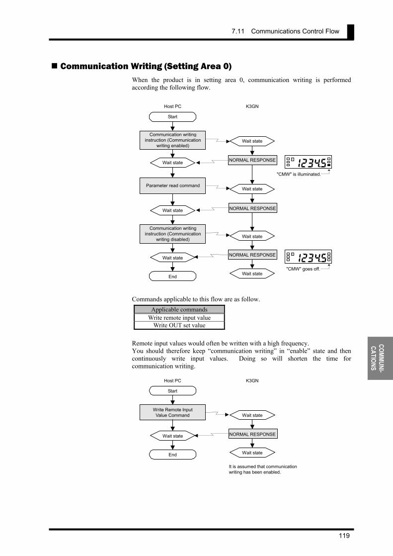
7.11 Communications Control Flow
119
COMMUNI- CATIONS
Communication Writing (Setting Area 0) When the product is in setting area 0, communication writing is performed according the following flow.
Commands applicable to this flow are as follow.
Applicable commands Write remote input value
Write OUT set value Remote input values would often be written with a high frequency. You should therefore keep “communication writing” in “enable” state and then continuously write input values. Doing so will shorten the time for communication writing.
Start
Wait state
Communication writinginstruction (Communication
writing enabled)Wait state
NORMAL RESPONSE
Wait state
End
Host PC K3GN
Parameter read command
Wait state NORMAL RESPONSE
Communication writing instruction (Communication
writing disabled) Wait state
Wait state
Wait state
1 2 3 $ 5 T
"CMW" is illuminated.
123$5T
"CMW" goes off.
NORMAL RESPONSE
Start
Wait state
Write Remote Input Value Command Wait state
NORMAL RESPONSE
Wait state End
Host PC K3GN
It is assumed that communication writing has been enabled.
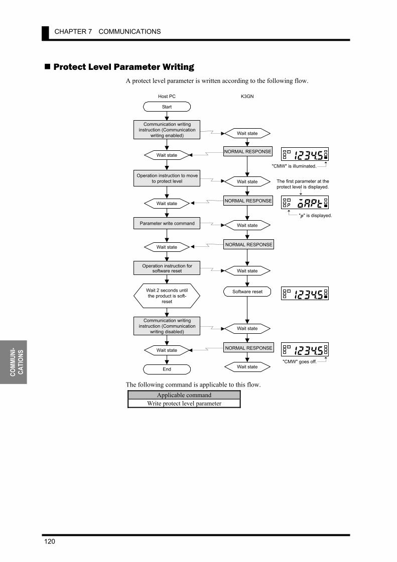
CHAPTER 7 COMMUNICATIONS
120
COMM
UNI-
CATI
ONS
Protect Level Parameter Writing A protect level parameter is written according to the following flow.
The following command is applicable to this flow. Applicable command
Write protect level parameter
Start
Wait state
Communication writing instruction (Communication
writing enabled) Wait state
NORMAL RESPONSE
Wait state
End
Host PC K3GN
Parameter write command
Wait state
NORMAL RESPONSE
Operation instruction for software reset
Wait state
NORMAL RESPONSE
Wait state
123$5f
T
"CMW" is illuminated.
123$5f
T
"CMW" goes off.
Operation instruction to move to protect level
Wait state 0oaptp
T
"p" is displayed.
Software reset
The first parameter at theprotect level is displayed.
123$5f
T
Communication writing instruction (Communication
writing disabled)
Wait 2 seconds until the product is soft-
reset
Wait state
Wait state
NORMAL RESPONSE
Wait state

7.11 Communications Control Flow
121
COMMUNI- CATIONS
Parameter Writing (Setting Area 1) When the product is in setting area 1, a parameter is written according to the following flow.
The following command is applicable to this flow.
Applicable command Write parameter (setting area 1)
Start
Wait state
Communication writing instruction (Communication
writing enabled) Wait state
NORMAL RESPONSE
Wait state
End
Host PC K3GN
Parameter write command
Wait state
NORMAL RESPONSE
Operation instruction for software reset
Wait state
NORMAL RESPONSE
Wait state
123$5f
T
"CMW" is illuminated.
1 2 3 $ 5 f
T
"CMW" goes off.
Action instruction to move to setting area 1
Wait state 0in-ts
T
"5" is displayed.
Software reset
The first parameter at the initial setting level is displayed.
123$5f
T
Communication writing instruction (Communication
writing disabled)
Wait 2 seconds until the product is soft-
reset
Wait state
Wait state
NORMAL RESPONSE
Wait state
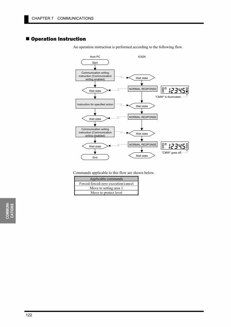
CHAPTER 7 COMMUNICATIONS
122
COMM
UNI-
CATI
ONS
Operation Instruction An operation instruction is performed according to the following flow.
Commands applicable to this flow are shown below.
Applicable commands Forced-forced-zero execution/cancel
Move to setting area 1 Move to protect level
Start
Wait state
Communication writinginstruction (Communication
writing enabled) Wait state
NORMAL RESPONSE
Wait state
End
Host PC K3GN
Instruction for specified action
Wait stateNORMAL RESPONSE
Communication writing instruction (Communication
writing disabled) Wait state
NORMAL RESPONSE Wait state
Wait state
1 2 3 $ 5 f
T
"CMW" is illuminated.
1 2 3 $ 5 f
T
"CMW" goes off.
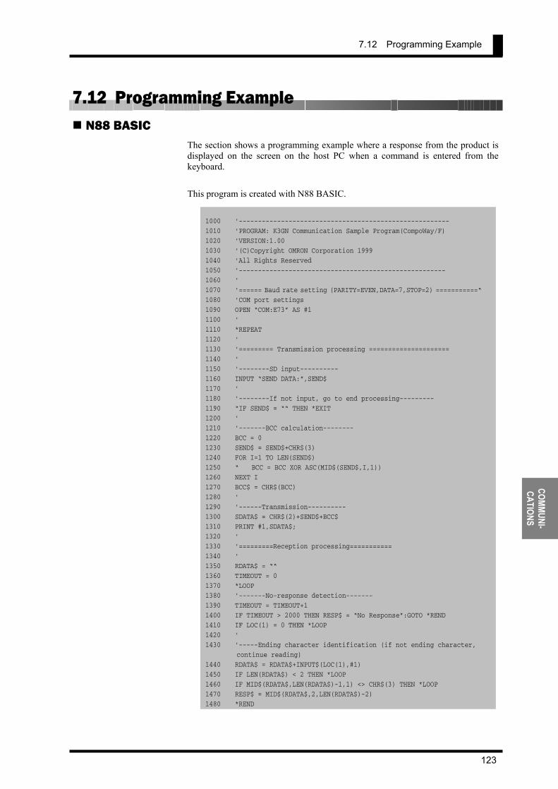
7.12 Programming Example
123
COMMUNI- CATIONS
7.12 Programming Example N88 BASIC
The section shows a programming example where a response from the product is displayed on the screen on the host PC when a command is entered from the keyboard. This program is created with N88 BASIC.
1000 '------------------------------------------------------- 1010 'PROGRAM: K3GN Communication Sample Program(CompoWay/F) 1020 'VERSION:1.00 1030 '(C)Copyright OMRON Corporation 1999 1040 'All Rights Reserved 1050 '------------------------------------------------------ 1060 ' 1070 '====== Baud rate setting (PARITY=EVEN,DATA=7,STOP=2) ===========“ 1080 'COM port settings 1090 OPEN “COM:E73” AS #1 1100 ' 1110 *REPEAT 1120 ' 1130 '========= Transmission processing ===================== 1140 ' 1150 '--------SD input---------- 1160 INPUT “SEND DATA:”,SEND$ 1170 ' 1180 '--------If not input, go to end processing--------- 1190 “IF SEND$ = ““ THEN *EXIT 1200 ' 1210 '-------BCC calculation-------- 1220 BCC = 0 1230 SEND$ = SEND$+CHR$(3) 1240 FOR I=1 TO LEN(SEND$) 1250 “ BCC = BCC XOR ASC(MID$(SEND$,I,1)) 1260 NEXT I 1270 BCC$ = CHR$(BCC) 1280 ' 1290 '------Transmission---------- 1300 SDATA$ = CHR$(2)+SEND$+BCC$ 1310 PRINT #1,SDATA$; 1320 ' 1330 '=========Reception processing=========== 1340 ' 1350 RDATA$ = ““ 1360 TIMEOUT = 0 1370 *LOOP 1380 '-------No-response detection------- 1390 TIMEOUT = TIMEOUT+1 1400 IF TIMEOUT > 2000 THEN RESP$ = “No Response”:GOTO *REND 1410 IF LOC(1) = 0 THEN *LOOP 1420 ' 1430 '-----Ending character identification (if not ending character,
continue reading) 1440 RDATA$ = RDATA$+INPUT$(LOC(1),#1) 1450 IF LEN(RDATA$) < 2 THEN *LOOP 1460 IF MID$(RDATA$,LEN(RDATA$)-1,1) <> CHR$(3) THEN *LOOP 1470 RESP$ = MID$(RDATA$,2,LEN(RDATA$)-2) 1480 *REND
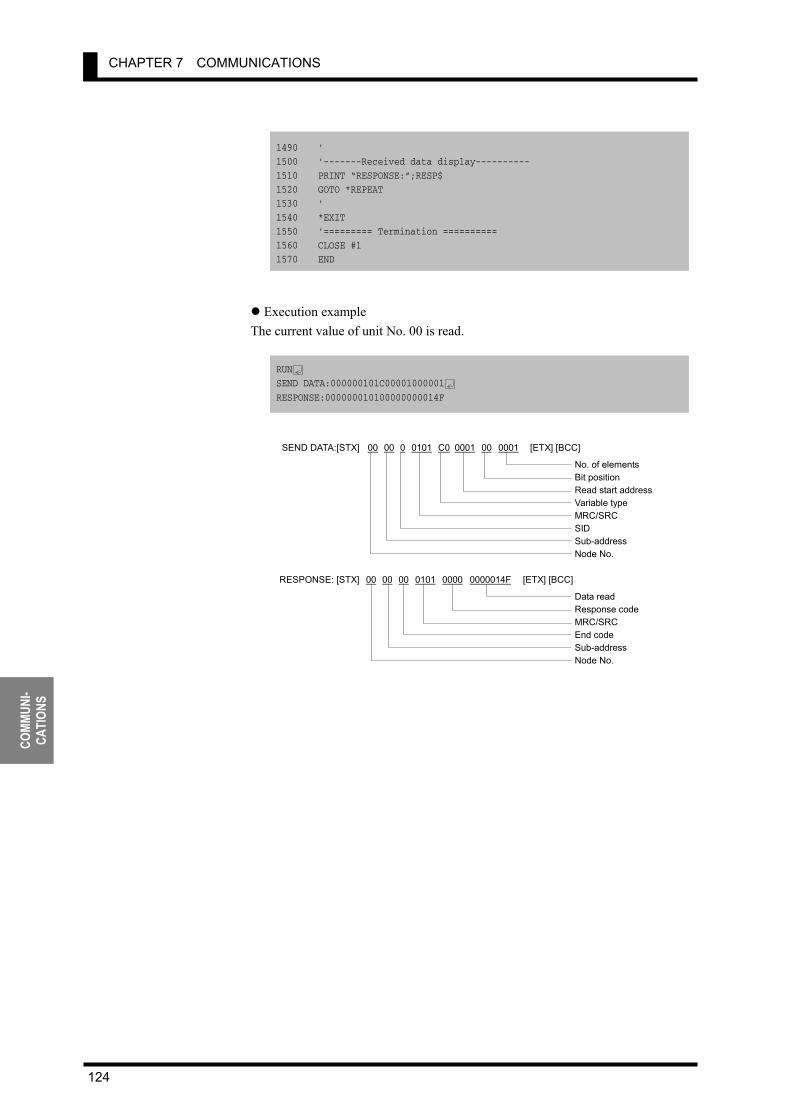
CHAPTER 7 COMMUNICATIONS
124
COMM
UNI-
CATI
ONS
1490 ' 1500 '-------Received data display---------- 1510 PRINT “RESPONSE:”;RESP$ 1520 GOTO *REPEAT 1530 ' 1540 *EXIT 1550 '========= Termination ========== 1560 CLOSE #1 1570 END
Execution example The current value of unit No. 00 is read.
RUN SEND DATA:000000101C00001000001 RESPONSE:000000010100000000014F
SEND DATA:[STX] 00 00 0 0101 C0 0001 00 0001 [ETX] [BCC] No. of elements Bit position Read start address Variable type MRC/SRC SIDSub-address Node No.
RESPONSE: [STX] 00 00 00 0101 0000 0000014F [ETX] [BCC] Data read Response code MRC/SRC End code Sub-address Node No.
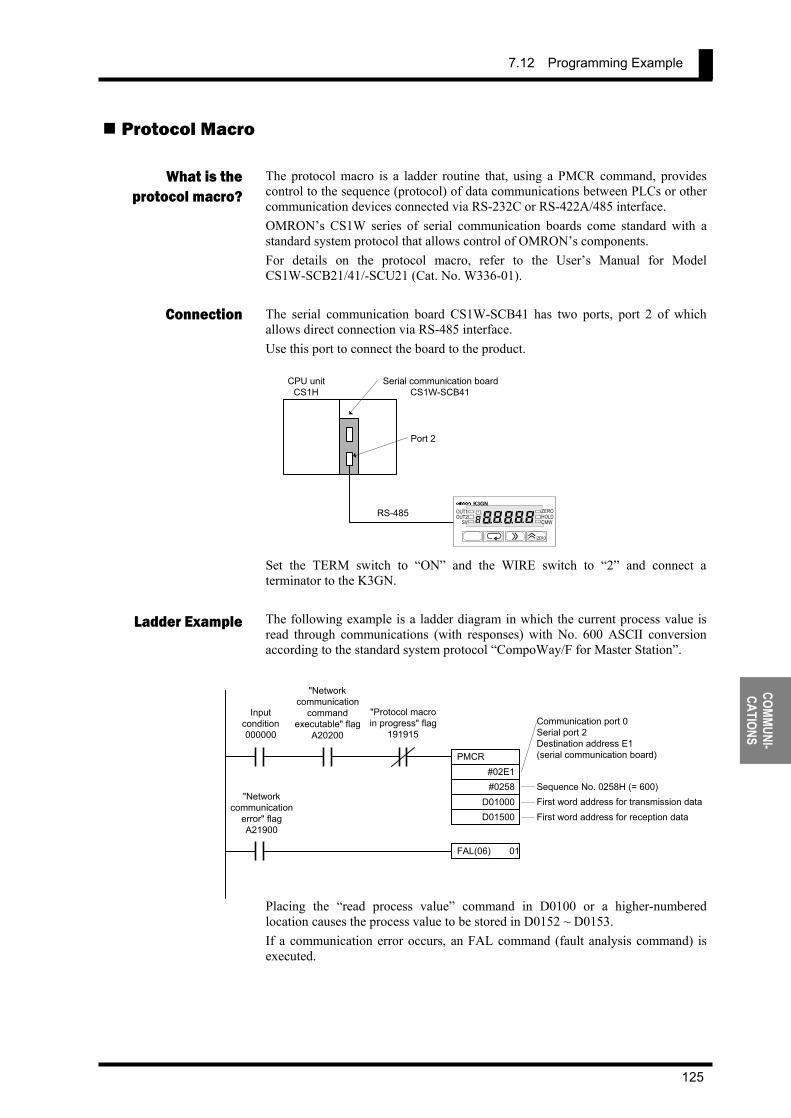
7.12 Programming Example
125
COMMUNI- CATIONS
Protocol Macro
The protocol macro is a ladder routine that, using a PMCR command, provides control to the sequence (protocol) of data communications between PLCs or other communication devices connected via RS-232C or RS-422A/485 interface. OMRON’s CS1W series of serial communication boards come standard with a standard system protocol that allows control of OMRON’s components. For details on the protocol macro, refer to the User’s Manual for Model CS1W-SCB21/41/-SCU21 (Cat. No. W336-01). The serial communication board CS1W-SCB41 has two ports, port 2 of which allows direct connection via RS-485 interface. Use this port to connect the board to the product.
Set the TERM switch to “ON” and the WIRE switch to “2” and connect a terminator to the K3GN. The following example is a ladder diagram in which the current process value is read through communications (with responses) with No. 600 ASCII conversion according to the standard system protocol “CompoWay/F for Master Station”.
Placing the “read process value” command in D0100 or a higher-numbered location causes the process value to be stored in D0152 ~ D0153. If a communication error occurs, an FAL command (fault analysis command) is executed.
What is the protocol macro?
Connection
Ladder Example
PMCR #02E1 #0258
D01000 D01500
Inputcondition000000
"Networkcommunication
commandexecutable" flag
A20200
"Protocol macroin progress" flag
191915Communication port 0Serial port 2Destination address E1(serial communication board)
Sequence No. 0258H (= 600)First word address for transmission dataFirst word address for reception data
FAL(06) 01
"Networkcommunication
error" flagA21900
CPU unit CS1H
Serial communication board CS1W-SCB41
Port 2
RS-485K3GN
/ZERO
ZERO HOLD OUT1
( ( 8 T
( 8( CMW OUT2SV
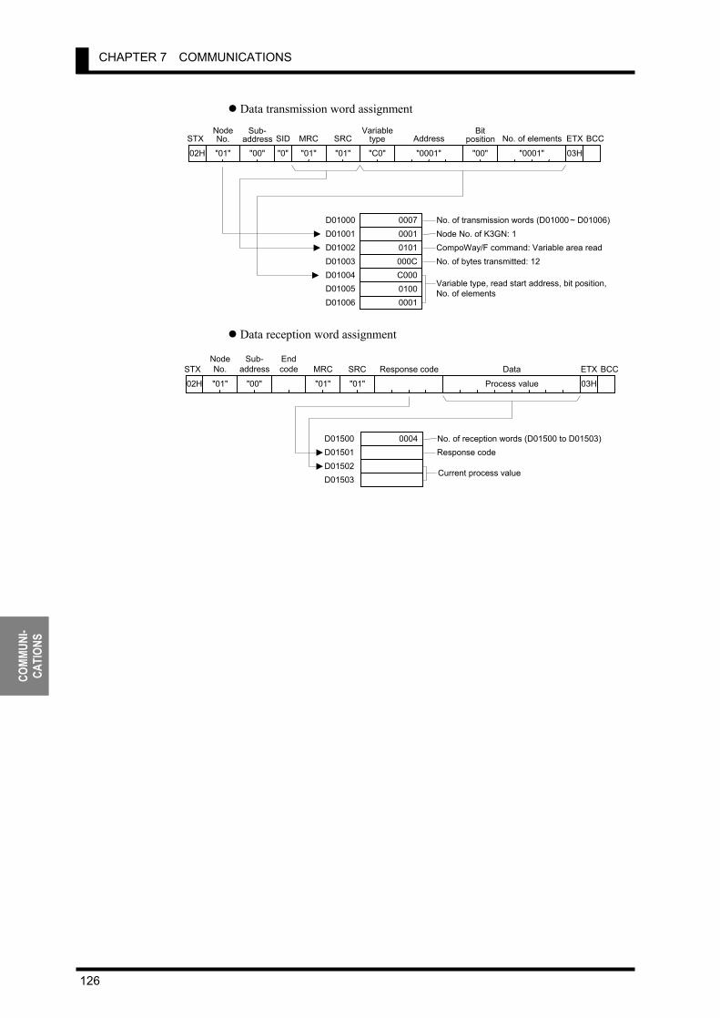
CHAPTER 7 COMMUNICATIONS
126
COMM
UNI-
CATI
ONS
Data transmission word assignment
Data reception word assignment
0004 No. of reception words (D01500 to D01503)Response code
D01500D01501D01502D01503
Current process value
Process value
MRC
"01"
SRC
"01"
Response code Data
03H
ETX BCCEndcode
Sub-address
"00"
NodeNo.
"01"02H STX
000700010101000CC00001000001
No. of transmission words (D01000~ D01006)Node No. of K3GN: 1CompoWay/F command: Variable area readNo. of bytes transmitted: 12
Variable type, read start address, bit position,No. of elements
D01000D01001D01002D01003D01004D01005D01006
MRC
"01"
SRC
"01"
Variabletype
"C0" "0001" Address
Bit position
"00" "0001"
No. of elements
"0"
SIDSub-
address
"00"
NodeNo.
"01"02H STX
03H
ETX BCC
7.12 Programming Example
127
USER CALIBRATION
8 USER CALIBRATION
8.1 User Calibration ・・・・・・・・・・・・・・・・・・・・・・・・・・・・・・・・・・・・・・・・・・ 128 8.2 User Calibration Processes・・・・・・・・・・・・・・・・・・・・・・・・・・・・・・・・・ 130
Connection of the Product to a STV/Calibration Procedure
The product allows the user to perform analog input calibration. This chapter outlines user calibration and describes how tocalibrate the product.
CHAPTER
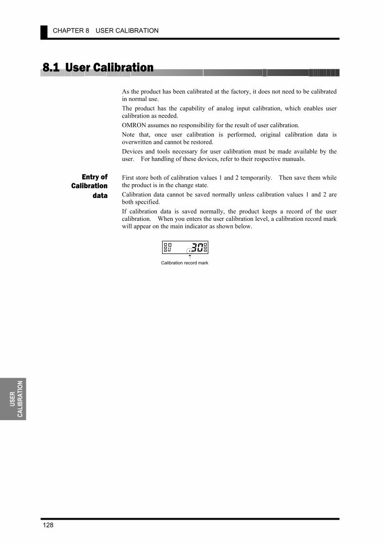
CHAPTER 8 USER CALIBRATION
128
USER
CA
LIBR
ATIO
N
8.1 User Calibration As the product has been calibrated at the factory, it does not need to be calibrated in normal use. The product has the capability of analog input calibration, which enables user calibration as needed. OMRON assumes no responsibility for the result of user calibration. Note that, once user calibration is performed, original calibration data is overwritten and cannot be restored. Devices and tools necessary for user calibration must be made available by the user. For handling of these devices, refer to their respective manuals. First store both of calibration values 1 and 2 temporarily. Then save them while the product is in the change state. Calibration data cannot be saved normally unless calibration values 1 and 2 are both specified. If calibration data is saved normally, the product keeps a record of the user calibration. When you enters the user calibration level, a calibration record mark will appear on the main indicator as shown below.
0i . 3 0 u
T
Calibration record mark
Entry ofCalibration
data
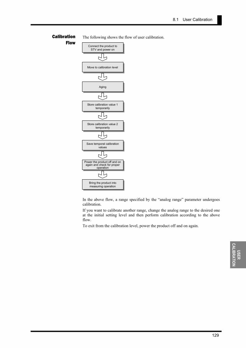
8.1 User Calibration
129
USER CALIBRATION
The following shows the flow of user calibration.
In the above flow, a range specified by the “analog range” parameter undergoes calibration. If you want to calibrate another range, change the analog range to the desired one at the initial setting level and then perform calibration according to the above flow. To exit from the calibration level, power the product off and on again.
CalibrationFlow Connect the product to
STV and power on
Aging
Move to calibration level
Store calibration value 1 temporarily
Store calibration value 2 temporarily
Save temporal calibration values
Power the product off and on again and check for proper
operation
Bring the product into measuring operation
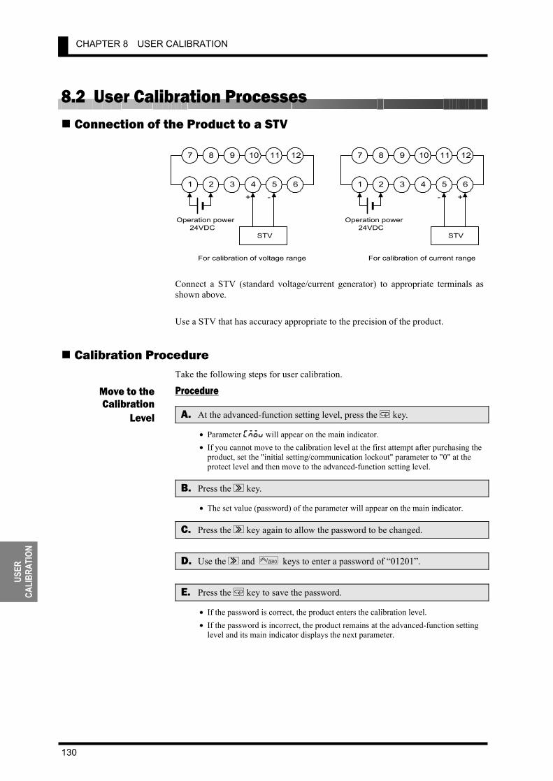
CHAPTER 8 USER CALIBRATION
130
USER
CA
LIBR
ATIO
N
8.2 User Calibration Processes Connection of the Product to a STV
Connect a STV (standard voltage/current generator) to appropriate terminals as shown above. Use a STV that has accuracy appropriate to the precision of the product.
Calibration Procedure Take the following steps for user calibration.
Procedure
A. At the advanced-function setting level, press the M key.
• Parameter cmov will appear on the main indicator. • If you cannot move to the calibration level at the first attempt after purchasing the
product, set the "initial setting/communication lockout" parameter to "0" at the protect level and then move to the advanced-function setting level.
B. Press the S key.
• The set value (password) of the parameter will appear on the main indicator.
C. Press the S key again to allow the password to be changed.
D. Use the S and ZERO/ keys to enter a password of “01201”.
E. Press the M key to save the password.
• If the password is correct, the product enters the calibration level. • If the password is incorrect, the product remains at the advanced-function setting
level and its main indicator displays the next parameter.
Move to theCalibration
Level
7 8 9 10 11 12
1 2 3 4 5 6
Operation power24VDC
STV
+ -
7 8 9 10 11 12
1 2 3 4 5 6
Operation power24VDC
STV
+-
For calibration of voltage range For calibration of current range
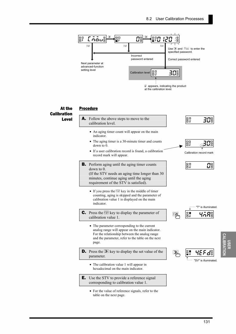
8.2 User Calibration Processes
131
USER CALIBRATION
Procedure
A. Follow the above steps to move to the calibration level.
• An aging timer count will appear on the main indicator.
• The aging timer is a 30-minute timer and counts down to 0.
• If a user calibration record is found, a calibration record mark will appear.
B. Perform aging until the aging timer counts down to 0. (If the STV needs an aging time longer than 30 minutes, continue aging until the aging requirement of the STV is satisfied).
• If you press the M key in the middle of timer counting, aging is skipped and the parameter of calibration value 1 is displayed on the main indicator.
C. Press the M key to display the parameter of calibration value 1.
• The parameter corresponding to the current analog range will appear on the main indicator. For the relationship between the analog range and the parameter, refer to the table on the next page.
D. Press the S key to display the set value of the parameter.
• The calibration value 1 will appear in hexadecimal on the main indicator.
E. Use the STV to provide a reference signal corresponding to calibration value 1.
• For the value of reference signals, refer to the table on the next page.
At theCalibration
Level 0in30u
T
0in30u
T
a4 e f d u
T
S
"SV" is illuminated.
0 . 3 0 u
T
Calibration record mark
ra4 m a u
T
M
"T" is illuminated.
cmovf
T
0f
T
0 1 2 01f T
30u T
S S
M M M
Use S and ZERO/ to enter the specified password.
Correct password enteredIncorrectpassword entered
Next parameter atadvanced-functionsetting level
Calibration level
u appears, indicating the product at the calibration level.
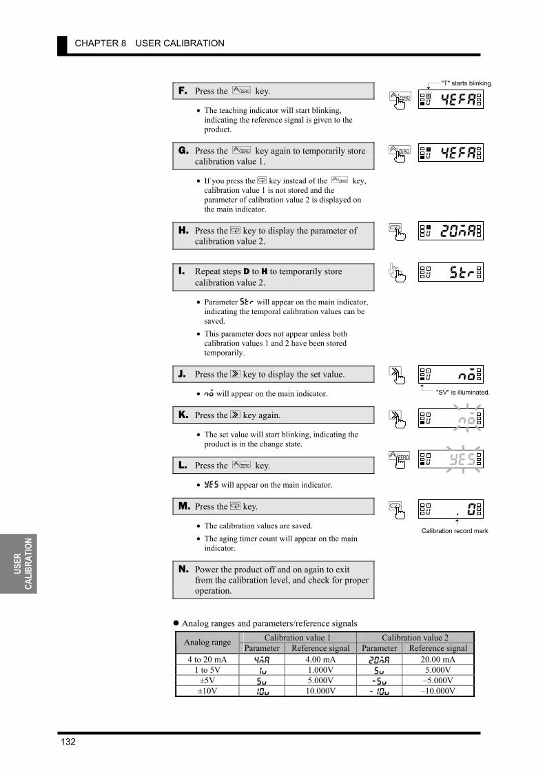
CHAPTER 8 USER CALIBRATION
132
USER
CA
LIBR
ATIO
N
F. Press the ZERO/ key.
• The teaching indicator will start blinking, indicating the reference signal is given to the product.
G. Press the ZERO/ key again to temporarily store calibration value 1.
• If you press the M key instead of the ZERO / key, calibration value 1 is not stored and the parameter of calibration value 2 is displayed on the main indicator.
H. Press the M key to display the parameter of calibration value 2.
I. Repeat steps D to H to temporarily store calibration value 2.
• Parameter str will appear on the main indicator, indicating the temporal calibration values can be saved.
• This parameter does not appear unless both calibration values 1 and 2 have been stored temporarily.
J. Press the S key to display the set value.
• no will appear on the main indicator.
K. Press the S key again.
• The set value will start blinking, indicating the product is in the change state.
L. Press the ZERO/ key.
• yes will appear on the main indicator.
M. Press the M key.
• The calibration values are saved. • The aging timer count will appear on the main
indicator.
N. Power the product off and on again to exit from the calibration level, and check for proper operation.
Analog ranges and parameters/reference signals
Calibration value 1 Calibration value 2 Analog rangeParameter Reference signal Parameter Reference signal
4 to 20 mA 4ma 4.00 mA 20ma 20.00 mA 1 to 5V 1v 1.000V 5v 5.000V
±5V 5v 5.000V -5v –5.000V ±10V 10v 10.000V -10v –10.000V
a4efau
T ZERO/
r20mau
TM
pustru
T
a4onou
TS
puyesu
T ZERO/
a4 e f a u
T ZERO/
"T" starts blinking.
ev .n0 u
TM
Calibration record mark
a4on o u
TS
"SV" is illuminated.

8.2 User Calibration Processes
133
TROUBLE-SHOOTING GUIDE
9 TROUBLESHOOTING GUIDE
9.1 Error Indications・・・・・・・・・・・・・・・・・・・・・・・・・・・・・・・・・・・・・・・・・・ 134 9.2 Troubleshooting Table ・・・・・・・・・・・・・・・・・・・・・・・・・・・・・・・・・・・・ 135
This chapter shows the meanings of error indications and theremedial actions to be taken in the event of error. It also containsa troubleshooting table that will be helpful in case a trouble mayarise.
CHAPTER
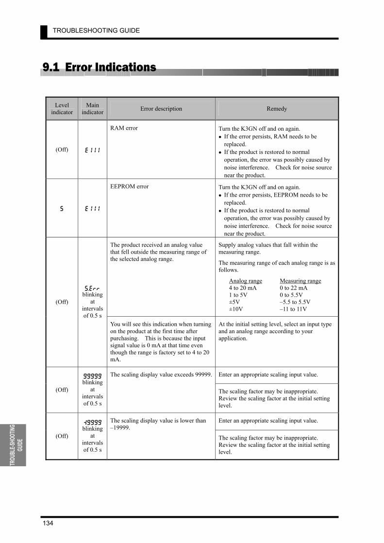
TROUBLESHOOTING GUIDE
134
TROU
BLE-S
HOOT
ING
GUIDE
9.1 Error Indications
Level indicator
Main indicator Error description Remedy
(Off) e111
RAM error Turn the K3GN off and on again. • If the error persists, RAM needs to be
replaced. • If the product is restored to normal
operation, the error was possibly caused by noise interference. Check for noise source near the product.
s e111
EEPROM error Turn the K3GN off and on again. • If the error persists, EEPROM needs to be
replaced. • If the product is restored to normal
operation, the error was possibly caused by noise interference. Check for noise source near the product.
The product received an analog value that fell outside the measuring range of the selected analog range.
Supply analog values that fall within the measuring range.
The measuring range of each analog range is as follows.
Analog range Measuring range 4 to 20 mA 0 to 22 mA 1 to 5V 0 to 5.5V ±5V –5.5 to 5.5V ±10V –11 to 11V
(Off)
s.err blinking
at intervals of 0.5 s
You will see this indication when turning on the product at the first time after purchasing. This is because the input signal value is 0 mA at that time even though the range is factory set to 4 to 20 mA.
At the initial setting level, select an input type and an analog range according to your application.
Enter an appropriate scaling input value.
(Off)
99999 blinking
at intervals of 0.5 s
The scaling display value exceeds 99999.
The scaling factor may be inappropriate. Review the scaling factor at the initial setting level.
Enter an appropriate scaling input value.
(Off)
:9999 blinking
at intervals of 0.5 s
The scaling display value is lower than –19999.
The scaling factor may be inappropriate. Review the scaling factor at the initial setting level.
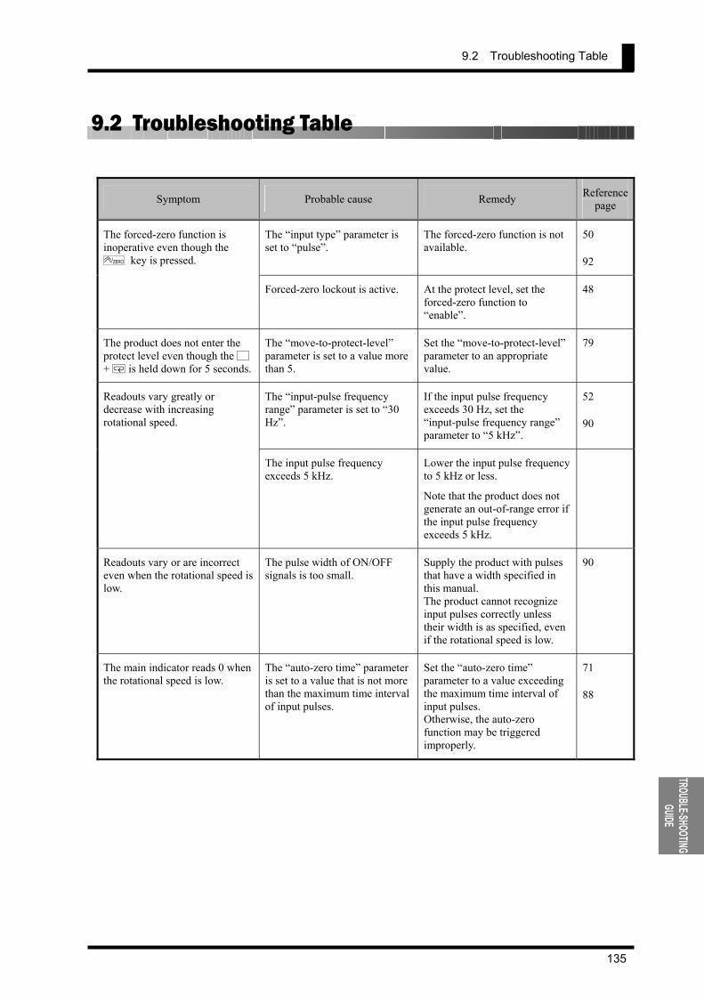
9.2 Troubleshooting Table
135
TROUBLE-SHOOTING GUIDE
9.2 Troubleshooting Table
Symptom Probable cause Remedy Reference page
The “input type” parameter is set to “pulse”.
The forced-zero function is not available.
50
92
The forced-zero function is inoperative even though the
ZERO / key is pressed.
Forced-zero lockout is active. At the protect level, set the forced-zero function to “enable”.
48
The product does not enter the protect level even though the L + M is held down for 5 seconds.
The “move-to-protect-level” parameter is set to a value more than 5.
Set the “move-to-protect-level” parameter to an appropriate value.
79
The “input-pulse frequency range” parameter is set to “30 Hz”.
If the input pulse frequency exceeds 30 Hz, set the “input-pulse frequency range” parameter to “5 kHz”.
52
90
Readouts vary greatly or decrease with increasing rotational speed.
The input pulse frequency exceeds 5 kHz.
Lower the input pulse frequency to 5 kHz or less.
Note that the product does not generate an out-of-range error if the input pulse frequency exceeds 5 kHz.
Readouts vary or are incorrect even when the rotational speed is low.
The pulse width of ON/OFF signals is too small.
Supply the product with pulses that have a width specified in this manual. The product cannot recognize input pulses correctly unless their width is as specified, even if the rotational speed is low.
90
The main indicator reads 0 when the rotational speed is low.
The “auto-zero time” parameter is set to a value that is not more than the maximum time interval of input pulses.
Set the “auto-zero time” parameter to a value exceeding the maximum time interval of input pulses. Otherwise, the auto-zero function may be triggered improperly.
71
88
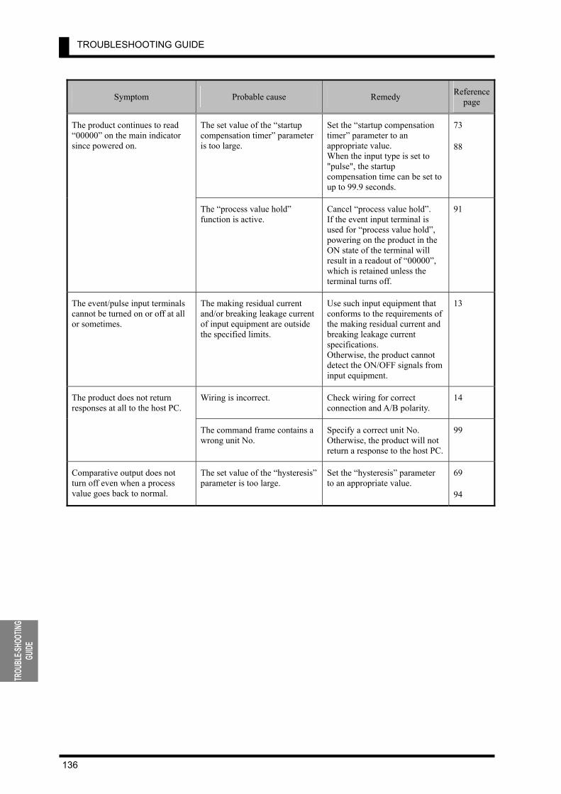
TROUBLESHOOTING GUIDE
136
TROU
BLE-S
HOOT
ING
GUIDE
Symptom Probable cause Remedy Reference page
The set value of the “startup compensation timer” parameter is too large.
Set the “startup compensation timer” parameter to an appropriate value. When the input type is set to "pulse", the startup compensation time can be set to up to 99.9 seconds.
73
88
The product continues to read “00000” on the main indicator since powered on.
The “process value hold” function is active.
Cancel “process value hold”. If the event input terminal is used for “process value hold”, powering on the product in the ON state of the terminal will result in a readout of “00000”, which is retained unless the terminal turns off.
91
The event/pulse input terminals cannot be turned on or off at all or sometimes.
The making residual current and/or breaking leakage current of input equipment are outside the specified limits.
Use such input equipment that conforms to the requirements of the making residual current and breaking leakage current specifications. Otherwise, the product cannot detect the ON/OFF signals from input equipment.
13
Wiring is incorrect. Check wiring for correct connection and A/B polarity.
14 The product does not return responses at all to the host PC.
The command frame contains a wrong unit No.
Specify a correct unit No. Otherwise, the product will not return a response to the host PC.
99
Comparative output does not turn off even when a process value goes back to normal.
The set value of the “hysteresis” parameter is too large.
Set the “hysteresis” parameter to an appropriate value.
69
94
APPENDIX
137
APPENDIX
10 APPENDIX
Specifications ・・・・・・・・・・・・・・・・・・・・・・・・・・・・・・・・・・・・・・・・・・・・ 138 Parameter List ・・・・・・・・・・・・・・・・・・・・・・・・・・・・・・・・・・・・・・・・・・・・ 142 ASCII Code Table ・・・・・・・・・・・・・・・・・・・・・・・・・・・・・・・・・・・・・・・・ 143
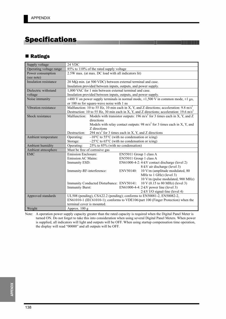
APPENDIX
138
APPE
NDIX
Specifications
Ratings Supply voltage 24 VDC Operating voltage range 85% to 110% of the rated supply voltage Power consumption (see note)
2.5W max. (at max. DC load with all indicators lit)
Insulation resistance 20 MΩ min. (at 500 VDC) between external terminal and case. Insulation provided between inputs, outputs, and power supply.
Dielectric withstand voltage
1,000 VAC for 1 min between external terminal and case. Insulation provided between inputs, outputs, and power supply.
Noise immunity ±480 V on power supply terminals in normal mode, ±1,500 V in common mode, ±1 µs, or 100 ns for square-wave noise with 1 ns
Vibration resistance Malfunction: 10 to 55 Hz, 10 min each in X, Y, and Z directions; acceleration: 9.8 m/s2 Destruction: 10 to 55 Hz, 30 min each in X, Y, and Z directions; acceleration: 19.6 m/s2
Shock resistance Malfunction: Models with transistor outputs: 196 m/s2 for 3 times each in X, Y, and Z directions
Models with relay contact outputs: 98 m/s2 for 3 times each in X, Y, and Z directions
Destruction: 294 m/s2 for 3 times each in X, Y, and Z directions Ambient temperature Operating: –10°C to 55°C (with no condensation or icing)
Storage: –25°C to 65°C (with no condensation or icing) Ambient humidity Operating: 25% to 85% (with no condensation) Ambient atmosphere Must be free of corrosive gas EMC Emission Enclosure: EN55011 Group 1 class A
Emission AC Mains: EN55011 Group 1 class A Immunity ESD: EN61000-4-2: 4-kV contact discharge (level 2) 8-kV air discharge (level 3) Immunity-RF-interference: ENV50140: 10 V/m (amplitude modulated, 80
MHz to 1 GHz) (level 3) 10 V/m (pulse modulated, 900 MHz) Immunity Conducted Disturbance: ENV50141: 10 V (0.15 to 80 MHz) (level 3) Immunity Burst: EN61000-4-4: 2-kV power line (level 3) 2-kV I/O signal-line (level 4)
Approved standards UL508 (pending), CSA22.2 (pending); conforms to EN50081-2, EN50082-2, EN61010-1 (IEC61010-1); conforms to VDE106/part 100 (Finger Protection) when the terminal cover is mounted.
Weight Approx. 100 g Note: A operation power supply capacity greater than the rated capacity is required when the Digital Panel Meter is
turned ON. Do not forget to take this into consideration when using several Digital Panel Meters. When power is supplied, all indicators will light and outputs will be OFF. When using startup compensation time operation, the display will read “00000” and all outputs will be OFF.
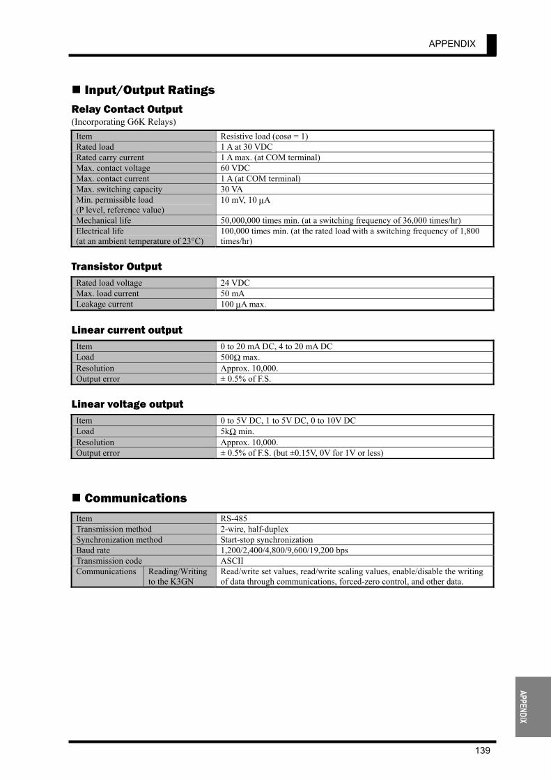
APPENDIX
139
APPENDIX
Input/Output Ratings Relay Contact Output (Incorporating G6K Relays)
Item Resistive load (cosø = 1) Rated load 1 A at 30 VDC Rated carry current 1 A max. (at COM terminal) Max. contact voltage 60 VDC Max. contact current 1 A (at COM terminal) Max. switching capacity 30 VA Min. permissible load (P level, reference value)
10 mV, 10 µA
Mechanical life 50,000,000 times min. (at a switching frequency of 36,000 times/hr) Electrical life (at an ambient temperature of 23°C)
100,000 times min. (at the rated load with a switching frequency of 1,800 times/hr)
Transistor Output
Rated load voltage 24 VDC Max. load current 50 mA Leakage current 100 µA max.
Linear current output
Item 0 to 20 mA DC, 4 to 20 mA DC Load 500Ω max. Resolution Approx. 10,000. Output error ± 0.5% of F.S.
Linear voltage output
Item 0 to 5V DC, 1 to 5V DC, 0 to 10V DC Load 5kΩ min. Resolution Approx. 10,000. Output error ± 0.5% of F.S. (but ±0.15V, 0V for 1V or less)
Communications Item RS-485 Transmission method 2-wire, half-duplex Synchronization method Start-stop synchronization Baud rate 1,200/2,400/4,800/9,600/19,200 bps Transmission code ASCII Communications Reading/Writing
to the K3GN Read/write set values, read/write scaling values, enable/disable the writing of data through communications, forced-zero control, and other data.
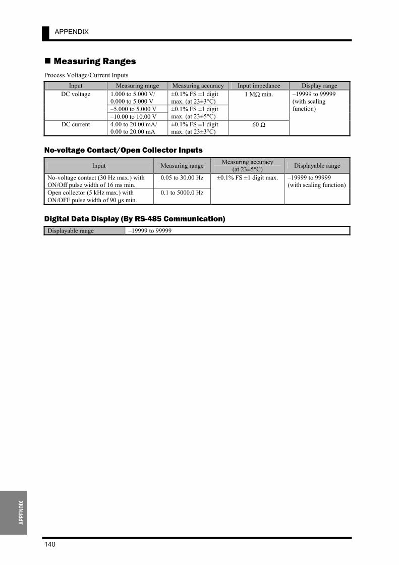
APPENDIX
140
APPE
NDIX
Measuring Ranges Process Voltage/Current Inputs
Input Measuring range Measuring accuracy Input impedance Display range 1.000 to 5.000 V/ 0.000 to 5.000 V
±0.1% FS ±1 digit max. (at 23±3°C)
–5.000 to 5.000 V
DC voltage
–10.00 to 10.00 V ±0.1% FS ±1 digit max. (at 23±5°C)
1 MΩ min.
DC current 4.00 to 20.00 mA/ 0.00 to 20.00 mA
±0.1% FS ±1 digit max. (at 23±3°C)
60 Ω
–19999 to 99999 (with scaling function)
No-voltage Contact/Open Collector Inputs
Input Measuring range Measuring accuracy (at 23±5°C) Displayable range
No-voltage contact (30 Hz max.) with ON/Off pulse width of 16 ms min.
0.05 to 30.00 Hz
Open collector (5 kHz max.) with ON/OFF pulse width of 90 µs min.
0.1 to 5000.0 Hz
±0.1% FS ±1 digit max. –19999 to 99999 (with scaling function)
Digital Data Display (By RS-485 Communication)
Displayable range –19999 to 99999
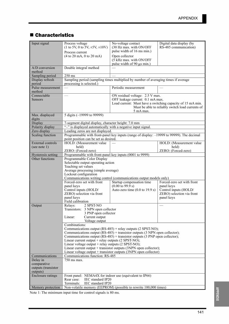
APPENDIX
141
APPENDIX
Characteristics Input signal Process voltage
(1 to 5V, 0 to 5V, ±5V, ±10V)Process current (4 to 20 mA, 0 to 20 mA)
No-voltage contact (30 Hz max. with ON/OFF pulse width of 16 ms min.) Open collector (5 kHz max. with ON/OFF pulse width of 90 µs min.)
Digital data display (by RS-485 communication)
A/D conversion method
Double integral method —
Sampling period 250 ms — Display refresh period
Sampling period (sampling times multiplied by number of averaging times if average processing is selected.)
Pulse measurement method
— Periodic measurement —
Connectable Sensors
— ON residual voltage: 2.5 V max. OFF leakage current: 0.1 mA max. Load current: Must have a switching capacity of 15 mA min. Must be able to reliably switch load currents of
5 mA max. Max. diaplayed digits
5 digits (–19999 to 99999)
Display 7-segment digital display, character height: 7.0 mm Polarity display “–” is displayed automatically with a negative input signal. Zero display Leading zeros are not displayed. Scaling function Programmable with front-panel key inputs (range of display: –19999 to 99999). The decimal
point position can be set as desired. External controls (see note 1)
HOLD: (Measurement value held)
ZERO: (Forced-zero)
— HOLD: (Measurement value held)
ZERO: (Forced-zero) Hysteresis setting Programmable with front-panel key inputs (0001 to 9999)
Programmable Color Display Selectable output operating action Teaching set values Average processing (simple average) Lockout configuration Communications writing control (communications output models only)
Other functions
Forced-zero set with front panel keys Control inputs (HOLD/ ZERO) selection via front panel keys Field calibration
Startup compensation time (0.00 to 99.9 s) Auto-zero time (0.0 to 19.9 s)
Forced-zero set with front panel keys Control inputs (HOLD/ ZERO) selection via front panel keys
Relays: 2 SPST-NO Transistors: 3 NPN open collector 3 PNP open collector Linear: Current output Voltage output
— Output
Combinations: Communications output (RS-485) + relay outputs (2 SPST-NO); Communications output (RS-485) + transistor outputs (3 NPN open collector); Communications output (RS-485) + transistor outputs (3 PNP open collector); Linear current output + relay outputs (2 SPST-NO); Linear voltage output + relay outputs (2 SPST-NO); Linear current output + transistor outputs (3NPN open collector); Linear voltage output + transistor outputs (3NPN open collector)
Communications Communications function: RS-485 Delay in comparative outputs (transistor outputs)
750 ms max.
Enclosure ratings Front panel: NEMA4X for indoor use (equivalent to IP66) Rear case: IEC standard IP20 Terminals: IEC standard IP20
Memory protection Non-volatile memory (EEPROM) (possible to rewrite 100,000 times) Note 1: The minimum input time for control signals is 80 ms.
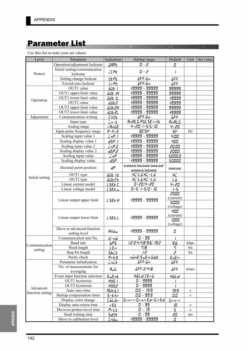
APPENDIX
142
APPE
NDIX
Parameter List
Use this list to note your set values. Level Parameter Indication Setting range Default Unit Set value
Operation/adjustment lockouts oapt 0 ~ 2 0 Initial setting/communication
lockouts icpt 0 ~ 2 1
Setting change lockout wtpt off/on off Protect
Forced-zero lockout zrpt off/on off OUT1 value out1 :9999 ~ 99999 99999
OUT1 upper-limit value out!h :9999 ~ 99999 99999 OUT1 lower-limit value out!l :9999 ~ 99999 :9999
OUT2 value out2 :9999 ~ 99999 :9999 OUT2 upper-limit value outBh :9999 ~ 99999 99999
Operation
OUT2 lower-limit value outBl :9999 ~ 99999 :9999 Adjustment Communication writing cmwt off/on off
Input type in-t analg/pulse/rmt analg Analog range range 4-20/1-5/5/10 4-20
Input-pulse frequency range p-fre 30/5k 5k Hz Scaling input value 1 inp.1 :9999 ~ 99999 4.00
Scaling display value 1 dsp.1 :9999 ~ 99999 400 Scaling input value 2 inp.2 :9999 ~ 99999 20.00
Scaling display value 2 dsp.2 :9999 ~ 99999 2000 Scaling input value inp :9999 ~ 99999 5000.0
Scaling display value dsp :9999 ~ 99999 50000
Decimal point position dp ,.,,,,/,,.,,,/,,,.,,/
,,,,.,/,,,,, ,,,.,,
OUT1 type out1.t hi/lo/hi-lo hi OUT2 type out2.t hi/lo/hi-lo lo
Linear current model lset.c 0-20/4-20 4-20 Linear voltage model lset.v 0-5/1-5/0-10 1-5
2000 (current)
Linear output upper limit lset.h :9999 ~ 99999 5000
(voltage)
400 (current)
Linear output lower limit lset.l :9999 ~ 99999 1000
(voltage)
Initial setting
Move to advanced-function setting level amov :9999 ~ 99999 0
Communication unit No. u-no 0 ~ 99 1 Baud rate bps 1.2/2.4/4.8/9.6/19.2 9.6 kbps
Word length len 7/8 7 bit Stop bit length sbit 1/2 2 bit
Communication setting
Parity check prty none/even/odd even Parameter initialization init off/on off
No. of measurements for averaging avg off/2/4/8 off times
Event input function selection event hold/zero hold OUT1 hysteresis hys1 0 ~ 9999 1 OUT2 hysteresis hys2 0 ~ 9999 1 Auto-zero time auto.z 0.0 ~ 19.9 19.9 s
Startup compensation timer s-tmr 0.0 ~ 99.9 0.0 s Display color change color grn-r/grn/red-g/red grn-r
Display auto-return time ret 0 ~ 99 10 s Move-to-protect-level time prlt 0 ~ 19 5 s
Send waiting time sdwt 0 ~ 99 20 ms
Advanced- function setting
Move to calibration level cmov :9999 ~ 99999 0
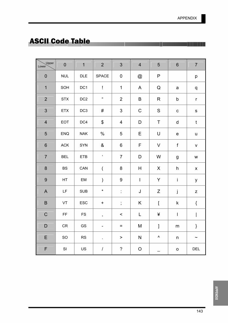
APPENDIX
143
APPENDIX
ASCII Code Table
Upper Lower 0 1 2 3 4 5 6 7
0 NUL DLE SPACE 0 @ P p
1 SOH DC1 ! 1 A Q a q
2 STX DC2 “ 2 B R b r
3 ETX DC3 # 3 C S c s
4 EOT DC4 $ 4 D T d t
5 ENQ NAK % 5 E U e u
6 ACK SYN & 6 F V f v
7 BEL ETB ‘ 7 D W g w
8 BS CAN ( 8 H X h x
9 HT EM ) 9 I Y i y
A LF SUB * : J Z j z
B VT ESC + ; K [ k
C FF FS , < L ¥ l |
D CR GS - = M ] m
E SO RS . > N ^ n ~
F SI US / ? O _ o DEL


Index
A adapter .................................................................. 10 address................................................................ 102 adjustment ............................................................ 38 adjustment level.................................................... 40 advanced-function setting..................................... 38 advanced-function setting level ............................ 40 alphabets............................................................... 44 analog input ...................................................... 5, 13 analog photoelectric sensor .................................. 20 analog range ................................................. 51, 116 ASCII character.................................................... 99 auto-zero............................................................... 88 auto-zero function................................................. 24 auto-zero time............................................... 71, 117 average processing ............................................... 89
B baud rate ............................................................. 117 BCC.............................................................. 99, 100
C calibration............................................................. 38 change state .......................................................... 44 chattering noise removal ...................................... 90 check and change OUT set value ......................... 45 clearing all parameters.......................................... 65 command frame.................................................... 99 command text ....................................................... 99 commands and responses ................................... 107 communication ..................................................... 14 communication parameters................................... 63 communication procedure .................................... 98 communication reading ...................................... 118 communication setting ......................................... 38 communication setting level................................. 40 communication specification................................ 98 communication unit No. ..................................... 117 communication writing....................................... 111 communication writing (setting area 0).............. 119 comparative output ..................................... 2, 14, 93 CompoWay/F ....................................................... 98 contact output ......................................................... 5 current leakage with transistor turned ON............ 13 current value....................................................... 115
D decimal point position .................................. 58, 117 dimensions............................................................ 10
display auto-return time ............................... 77, 117 display color......................................................... 75 display color change..................................... 95, 117
E echoback test .............................................. 101, 114 end code ............................................................. 100 error indications ................................................. 134 ETX.............................................................. 99, 100 event input................................................ 13, 67, 90 event input function ........................................... 117 event input/pulse input ........................................... 5
F FINS..................................................................... 98 forced-forced-zero execution ............................. 105 forced-zero ........................................... 3, 46, 90, 92 forced-zero cancel .............................................. 105 forced-zero execution/cancel ............................. 111 forced-zero lockout ...................................... 48, 116 frame .................................................................... 99
H hexadecimal number ............................................ 99 hysteresis.................................................. 20, 69, 94
I I/O circuits ............................................................. 5 I/O terminal connections ...................................... 12 initial setting................................................... 30, 38 initial setting level................................................ 40 initial setting/communication lockouts ........ 48, 116 input circuit diagrams............................................. 5 input pulse frequency ................................... 84, 116 input range over ................................................... 30 input type ..................................................... 50, 116 input-pulse frequency range................................. 52 inrush current ....................................................... 19 installation............................................................ 10 installation procedure........................................... 11 internal block diagram ........................................... 6
K key protect............................................................ 48
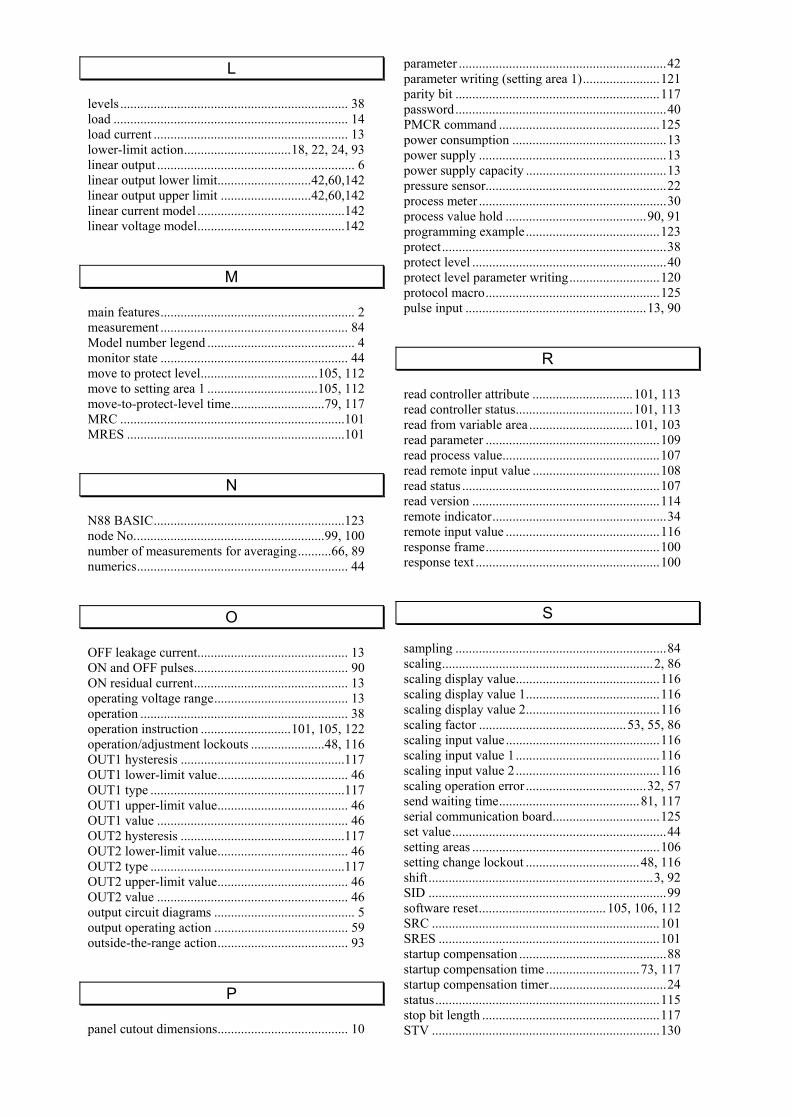
L levels .................................................................... 38 load ...................................................................... 14 load current .......................................................... 13 lower-limit action................................18, 22, 24, 93 linear output ........................................................... 6 linear output lower limit............................42,60,142 linear output upper limit ...........................42,60,142 linear current model ............................................142 linear voltage model............................................142
M main features.......................................................... 2 measurement ........................................................ 84 Model number legend ............................................ 4 monitor state ........................................................ 44 move to protect level...................................105, 112 move to setting area 1 .................................105, 112 move-to-protect-level time............................79, 117 MRC ...................................................................101 MRES .................................................................101
N N88 BASIC.........................................................123 node No.........................................................99, 100 number of measurements for averaging..........66, 89 numerics............................................................... 44
O OFF leakage current............................................. 13 ON and OFF pulses.............................................. 90 ON residual current.............................................. 13 operating voltage range........................................ 13 operation .............................................................. 38 operation instruction ...........................101, 105, 122 operation/adjustment lockouts ......................48, 116 OUT1 hysteresis .................................................117 OUT1 lower-limit value....................................... 46 OUT1 type ..........................................................117 OUT1 upper-limit value....................................... 46 OUT1 value ......................................................... 46 OUT2 hysteresis .................................................117 OUT2 lower-limit value....................................... 46 OUT2 type ..........................................................117 OUT2 upper-limit value....................................... 46 OUT2 value ......................................................... 46 output circuit diagrams .......................................... 5 output operating action ........................................ 59 outside-the-range action....................................... 93
P panel cutout dimensions....................................... 10
parameter ..............................................................42 parameter writing (setting area 1).......................121 parity bit .............................................................117 password...............................................................40 PMCR command ................................................125 power consumption ..............................................13 power supply ........................................................13 power supply capacity ..........................................13 pressure sensor......................................................22 process meter ........................................................30 process value hold ..........................................90, 91 programming example........................................123 protect...................................................................38 protect level ..........................................................40 protect level parameter writing...........................120 protocol macro....................................................125 pulse input ......................................................13, 90
R read controller attribute ..............................101, 113 read controller status...................................101, 113 read from variable area ...............................101, 103 read parameter ....................................................109 read process value...............................................107 read remote input value ......................................108 read status ...........................................................107 read version ........................................................114 remote indicator....................................................34 remote input value ..............................................116 response frame....................................................100 response text .......................................................100
S sampling ...............................................................84 scaling...............................................................2, 86 scaling display value...........................................116 scaling display value 1........................................116 scaling display value 2........................................116 scaling factor ............................................53, 55, 86 scaling input value..............................................116 scaling input value 1...........................................116 scaling input value 2...........................................116 scaling operation error ....................................32, 57 send waiting time..........................................81, 117 serial communication board................................125 set value................................................................44 setting areas ........................................................106 setting change lockout ..................................48, 116 shift...................................................................3, 92 SID .......................................................................99 software reset...................................... 105, 106, 112 SRC ....................................................................101 SRES ..................................................................101 startup compensation ............................................88 startup compensation time ............................73, 117 startup compensation timer...................................24 status...................................................................115 stop bit length .....................................................117 STV ....................................................................130
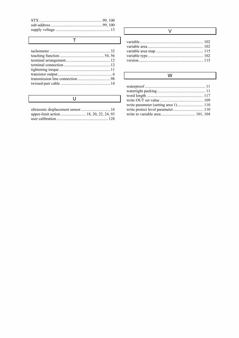
STX .............................................................. 99, 100 sub-address ................................................... 99, 100 supply voltage ...................................................... 13
T tachometer ............................................................ 32 teaching function ............................................ 54, 56 terminal arrangement............................................ 12 terminal connection .............................................. 12 tightening torque .................................................. 11 transistor output...................................................... 6 transmission line connection ................................ 98 twisted-pair cable ................................................. 14
U ultrasonic displacement sensor ............................. 16 upper-limit action ......................... 18, 20, 22, 24, 93 user calibration ................................................... 128
V variable............................................................... 102 variable area ....................................................... 102 variable area map ............................................... 115 variable type....................................................... 102 version................................................................ 115
W waterproof ............................................................ 11 watertight packing................................................ 11 word length ........................................................ 117 write OUT set value ........................................... 109 write parameter (setting area 1).......................... 110 write protect level parameter.............................. 110 write to variable area.................................. 101, 104

Cat.N
o.N
102-E1-04
User's
Man
ual
K3G
ND
IND
igitalP
anelM
eter
User's Manual
Cat. No. N102-E1-04
Authorized Distributor:
Cat. No. N102-E1-04 Note: Specifications subject to change without notice. Printed in Japan
0506-0.5M (0300) (C)
DIN Digital Panel Meter1/321/32
OMRON CorporationIndustrial Automation Company
Control Devices Division H.Q.Analog Controller DivisionShiokoji Horikawa, Shimogyo-ku,Kyoto, 600-8530 JapanTel: (81)75-344-7080/Fax: (81)75-344-7189
Regional Headquarters
OMRON EUROPE B.V.Wegalaan 67-69, NL-2132 JD HoofddorpThe NetherlandsTel: (31)2356-81-300/Fax: (31)2356-81-388
OMRON ELECTRONICS LLC1 East Commerce Drive, Schaumburg, IL 60173U.S.A.Tel: (1)847-843-7900/Fax: (1)847-843-8568
OMRON ASIA PACIFIC PTE. LTD.83 Clemenceau Avenue,#11-01, UE Square,239920 SingaporeTel: (65)6835-3011/Fax: (65)6835-2711
OMRON (CHINA) CO., LTD.Room 2211, Bank of China Tower,200 Yin Cheng Road (M),Shanghai, 200120 ChinaTel: (86)21-5037-2222/Fax: (86)21-5037-2200