Embed Size (px)
Citation preview

K3MA-L Temperature Meter
Highly Visible LCD Display with 2-color (Red and Green) LEDs■ Wide input range - select from two types of plati-num-resistance thermometers and ten types ofthermocouples.
■ Front-panel key operation for easy setting.
■ Average processing function suppresses flicker.
■ Temperature input shift and temperature unitselection functions.
■ Easy confirmation of max/min display.
■ Short 80-mm depth (measured from edge of faceplate).
■ Finger protective cover (standard equipment) pro-tects against electric shock.
■ Water- and dust-proof NEMA4X (IP66 equivalent)front panel.
■ Recognized to U.S. and Canadian requirementsunder the Component Recognition Program of ULwith CE marking.
Ordering Information
Model Number Legend:
1. Input Type
L: Platinum-resistance thermometer or thermocouple
2. Output Type
None: No output
C: With relay contact output (SPDT)
3. Supply Voltage
100-240VAC: 100 to 240 VAC
24VAC/VDC: 24 VAC/VDC
C�US
Input type Supply voltage Output Model
Platinum-resistance thermometer or thermocouple
100 to 240 VAC None K3MA-L 100-240VAC
1 relay contact output (SPDT) K3MA-L-C 100-240VAC
24 VAC/VDC None K3MA-L 24VAC/VDC
1 relay contact output (SPDT) K3MA-L-C 24VAC/VDC
K3MA-L-@ 1 2 3
1

K3MA-LK3MA-L
Specifications■ Ratings
Input/Output Ratings
Relay Contact Output
K3MA-L 100-240VAC, K3MA-L-C 100-240VAC K3MA-L 24VAC/VDC, K3MA-L-C 24VAC/VDC
Supply voltage 100 to 240 VAC 24 VAC (50/60 Hz), 24 VDC
Operating voltage range 85% to 110% of the rated supply voltage
Power consumption (under maximum load)
6 VA max. 4.5 VA max. (24 VAC)4.5 W max. (24 VDC)
Insulation resistance 20 M� min. (at 500 VDC) between external terminal and case.Insulation provided between inputs, outputs, and power supply.
Dielectric withstand voltage 2,000 VAC for 1 min between external terminal and case.Insulation provided between inputs, outputs, and power supply.
Noise immunity �1,500 V on power supply terminals in normal or common mode.�1 �s, or 100 ns for square-wave noise with 1 ns.
�480 V on power supply terminals in normal mode. �1,500 V in common mode.�1 �s, or 100 ns for square-wave noise with 1 ns.
Vibration resistance Vibration: 10 to 55 Hz, Acceleration: 50 m/s2
5 min each in X, Y, and Z directions for 10 sweeps.
Shock resistance 150 m/s2 (100 m/s2 for relay contact outputs) 3 times each on 3 axes, 6 directions.
Ambient temperature Operating: �10�C to 55�C (with no condensation or icing)Storage: �25�C to 65�C (with no condensation or icing)
Ambient humidity Operating: 25% to 85% (with no condensation)
Ambient atmosphere Must be free of corrosive gas.
Approved safety standards UL3121, conforms to EN61010-1 (Pollution degree 2/overvoltage category II) Conforms to VDE0106/P100 (finger protection)
EMC (EMI) EN61326+A1 IndustryEmission Enclosure: CISPR 11 Group 1 class A: CISRP16-1/-2
Emission AC Mains: CISPR 11 Group 1 class A: CISRP16-1/-2(EMS) EN61326+A1 IndustryImmunity ESD: EN61000-4-2: 4-kV contact discharge
8-kV air dischargeImmunity RF-interference: EN61000-4-3: 10 V/m (amplitude-modulated, 80 MHz to 1 GHz)
Electrical Fast Transient Noise: EN61000-4-4: 2 kV (power line)
Immunity Burst Noise: 1 kV line to line (I/O signal line)Immunity Surge: EN61000-4-5: 1 kV (power line)
2-kV line to ground (power line)Immunity Conducted Disturbance: EN61000-4-6: 3 V (0.15 to 80 MHz)Immunity Voltage Dip/Interrupting: EN61000-4-11: 0.5 cycle, 0, 180�� 100% (rated voltage)
Weight Approx. 200 g
Item Resistive load (cos� = 1) Inductive load (cos� = 0.4, L/R = 7 ms)
Rated load 5 A at 250 VAC, 5 A at 30 VDC 1.5 A at 250 VAC, 1.5 A at 30 VDC
Rated carry current 5 A max. (at COM terminal)
Max. contact voltage 400 VAC, 150 VDC
Max. contact current 5 A (at COM terminal)
Max. switching capacity 2,000 VA, 192 W 375 VA, 36 W
Min. permissible load (P level, reference value)
10 mA at 5 VDC
Mechanical life 20,000,000 times min. (at a switching frequency of 1,200 time/min)
Electrical life (at an ambient temperature of 20�C)
100,000 times min. (at a rated load switching frequency of 10 time/min)
2

K3MA-LK3MA-L
■ Measuring Ranges
Platinum-resistance Thermometer
Thermocouple
■ Characteristics
Note: The indication accuracy of the K thermocouple at a temperature of �200 to 1300�C is �2�C��1 digit maximum.The indication accuracy of the T and N thermocouples at a temperature of �100�C or less is �2�C��1 digit maximum.The indicator accuracy of the U and L thermocouples at any temperature is �2�C��1 digit maximum.The indication accuracy of the B thermocouple at a temperature of 400�C or less is unrestricted.The indication accuracy of the R and S thermocouples at a temperature of 200�C or less is �3�C��1 digit maximum.
Input Pt100 JPt100
Range �C �200 to 850 �199.9 to 500.0 0.0 to 100.0 �199.9 to 500.0 0.0 to 100.0
�F �300 to 1500 �199.9 to 900.0 0.0 to 210.0 �199.9 to 900.0 0.0 to 210.0
Parameter � � � � �
Input K J T E L U N R S B
Range �C �200 to 1300
�20.0 to 500.0
�100 to 850
�20.0 to 400.0
�200 to 400
�199.9 to 400.0
0 to 600
�100 to 850
�200 to 400
�199.9 to 400.0
�200 to 1300
0 to 1700
0 to 1700
100 to 1800
�F �300 to 2300
0.0 to 900.0
�100 to 1500
0.0to 750
�300 to 700
�199.9 to 700.0
0 to 1100
�100 to 1500
�300 to 700
�199.9 to 700.0
�300 to 2300
0 to 3000
0 to 3000
300 to 3200
Parameter � � � �� �� �� �� �� �� �� �� �
Indication accuracy (at 23�5�C) (See note.)
Thermocouple:(�0.5% of indication value or �1�C, whichever greater) �1 digit max.
Platinum-resistance thermometer:(�0.5% of indication value or �1�C, whichever greater) �1 digit max.
Input Thermocouple: K, J, T, E, L, U, N, R, S, BPlatinum-resistance thermometer: JPt100, Pt100
Measurement method Double integral method
Sampling period 500 ms
Display refresh period Sampling period (sampling times multiplied by number of averaging times if average processing is selected.)
Max. displayed digits 4 digits (�1999 to 9999)
Display 7-segment digital display, Character height: 14.2 mm
Polarity display “�” is displayed automatically with a negative input signal.
Zero display Leading zeros are not displayed.
Input shift Input shift equivalent to the setting value supported for all points within the sensor measurement range.
Hold function Max hold (maximum value), Min hold (minimum value)
Hysteresis setting Programmable with front-panel key inputs (0001 to 9999).
Other functions Display color change (green (red), green, red (green), red)Average processing (simple average OFF/2/4/8 operations)Setting change lockoutParameter initialization
Output Relay contact (SPDT)
Delay in comparative outputs 1 s max.
Enclosure ratings Front panel: NEMA4X for indoor use (equivalent to IP66)Rear case: IEC standard IP20Terminals: IEC standard IP00 + finger protection (VDE0106/100)
Memory protection Non-volatile memory (EEPROM) (possible to rewrite 100,000 times)
3

K3MA-LK3MA-L
Nomenclature
Name Functions
1. Main indicator Displays current values, parameters, and set values.
2. Opera-tion indi-cators
1 Lit when output 1 is ON.
SV Lit when a set value is being displayed or changed.
Max Lit when the main indicator is showing the MAX value.
Min Lit when the main indicator is showing the MIN value.
3. Level indicator Displays the current level that the K3MA-L is in. (See below for details.)
4. MAX/MIN Key Used to display the MAX and MIN values when a measurement value is being displayed.
5. Level Key Used to change the level.
6. Mode Key Used to allow the main indicator to indicate parameters sequentially.
7. Shift Key Used to enable a set value to be changed. When changing a set value, this key is used to move along the digits.
8. Up Key Used to change a set value. Used to set or clear a forced-zero function when a measurement value is being dis-played.
Level indicator Level
� Protect
Not lit Operation
� Adjustment
� Initial setting
� Advanced-function setting
MAX/MIN LEVEL SHIFTMODE UP
1
SV
MaxMin
2. Operation indicators
1. Main indicator
8. Up key
6. Mode key 7. Shift key5. Level key
4. MAX/MIN key
3. Level indicator
4
K3MA-LK3MA-L
Operation■ Main Functions
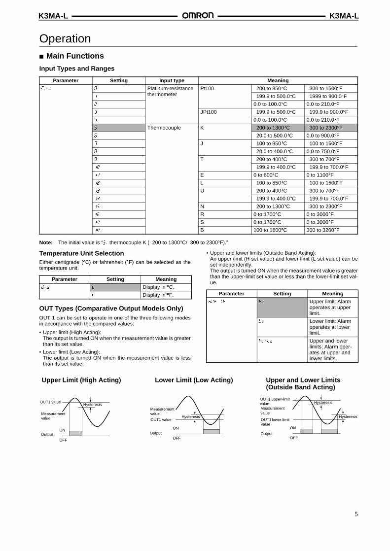
Input Types and Ranges
Note: The initial value is “���thermocouple K (�200 to 1300�C/�300 to 2300�F).”
Temperature Unit SelectionEither centigrade (�C) or fahrenheit (�F) can be selected as thetemperature unit.
OUT Types (Comparative Output Models Only)OUT 1 can be set to operate in one of the three following modesin accordance with the compared values:
• Upper limit (High Acting):The output is turned ON when the measurement value is greaterthan its set value.
• Lower limit (Low Acting):The output is turned ON when the measurement value is lessthan its set value.
• Upper and lower limits (Outside Band Acting):An upper limit (H set value) and lower limit (L set value) can beset independently. The output is turned ON when the measurement value is greaterthan the upper-limit set value or less than the lower-limit set val-ue.
Parameter Setting Input type Meaning
��� � Platinum-resistance thermometer
Pt100 �200 to 850�C �300 to 1500�F
� �199.9 to 500.0�C �1999 to 900.0�F
� 0.0 to 100.0�C 0.0 to 210.0�F
� JPt100 �199.9 to 500.0�C �199.9 to 900.0�F
� 0.0 to 100.0�C 0.0 to 210.0�F
� Thermocouple K �200 to 1300�C �300 to 2300�F
� �20.0 to 500.0�C 0.0 to 900.0�F
� J �100 to 850�C �100 to 1500�F
�20.0 to 400.0�C 0.0 to 750.0�F
T �200 to 400�C �300 to 700�F
�� �199.9 to 400.0�C �199.9 to 700.0�F
�� E 0 to 600�C 0 to 1100�F
�� L �100 to 850�C �100 to 1500�F
�� U �200 to 400�C �300 to 700�F
�� �199.9 to 400.0�C �199.9 to 700.0�F
�� N �200 to 1300�C �300 to 2300�F
�� R 0 to 1700�C 0 to 3000�F
�� S 0 to 1700�C 0 to 3000�F
� B 100 to 1800�C 300 to 3200�F
Parameter Setting Meaning
��� � Display in �C.
� Display in �F. Parameter Setting Meaning
������� � Upper limit: Alarm operates at upper limit.
�� Lower limit: Alarm operates at lower limit.
� ��� Upper and lower limits: Alarm oper-ates at upper and lower limits.
ON
OFF
ON
OFF
ON
OFF
Upper Limit (High Acting) Lower Limit (Low Acting) Upper and Lower Limits (Outside Band Acting)
Hysteresis
Hysteresis
HysteresisOUT1 value
Measurement value
Output
Measurement value
OUT1 value
Output
OUT1 upper-limit valueMeasurement value
OUT1 lower-limit value
Output
Hysteresis
5

K3MA-LK3MA-L
Temperature Input ShiftInput shift equivalent to the setting value supported for all points within the sensor measurement range.
Parameter InitializationThis function returns all of the parameters to their initial values.
Use this to reset the K3MA-L after returning it to its factory-setcondition.
Average ProcessingAverage processing stabilizes displayed values to minimize flickerby averaging the fluctuating input signals. Average processingcan be performed for the measurement values in either of foursteps (OFF, 2 times, 4 times, or 8 times).
This is useful for ignoring rapid fluctuations, e.g., eliminating spikenoise.
Hysteresis (Comparative Output Models Only)The hysteresis of comparative outputs can be set to prevent chat-tering in the output when the measurement value fluctuates finelynear the OUT value.
Changing the Display ColorThe color of the value displayed can be set to either red or green.For comparative output models, the display color can be set tochange from green to red, or from red to green, according to thestatus of the comparison criterion.
Display Auto-return TimeThis function automatically returns the display to the operationlevel’s current value if no keys are pressed for a preset time(called the display auto-return time).
Move-to-Protect-Level TimeThe time required to shift to the protect level can be set asdesired.
MAX/MIN DisplayThe maximum and minimum measurement (display) values fromthe time the power is turned ON until the current time can bestored and displayed. This is useful, for example, when measur-ing the maximum value.
Parameter Setting
�� �� to
Parameter Setting Meaning
� � ��� ---
�� Initializes all param-eters.
Temperature
Before shift
Temperature input shift value
After shift
Input
Upper limit (high acting)
Set value
OutputON
OFF
Hysteresis
Measurement value
192.0
258.9OUT1 value
Green
Red
MAX/MIN LEVEL SHIFTMODE UP
MAX/MIN
MAX/MIN
MAX/MIN
MAX/MIN
Max
LEVEL SHIFTMODE UP
MAX/MIN
Min
LEVEL SHIFTMODE UP
Current value
MAX value
MIN value
6

K3MA-LK3MA-L
■ External Connections
Terminal Arrangement
Output terminals
Input terminals
Power supply
E1
E2
A1
A2
E3
E4
E5
E6
+
−
E4
E5
E6
A
B
B
Models with comparative output
For platinum-resistance thermometer input
For thermocouple input
100- to 240-VAC type or 24-VAC/VDC type
(No polarity for 24-VDC connection.)
Terminal No. Name Description
Operation power Connects the operation power supply.
Thermocouple or platinum-resistance ther-mometer input
Connects the thermocouple or platinum-re-sistance thermometer input.
Outputs Outputs the relay outputs.
A1 A2-
E6 E5-E4 -
E2 E3-E1 ,
7
K3MA-LK3MA-L
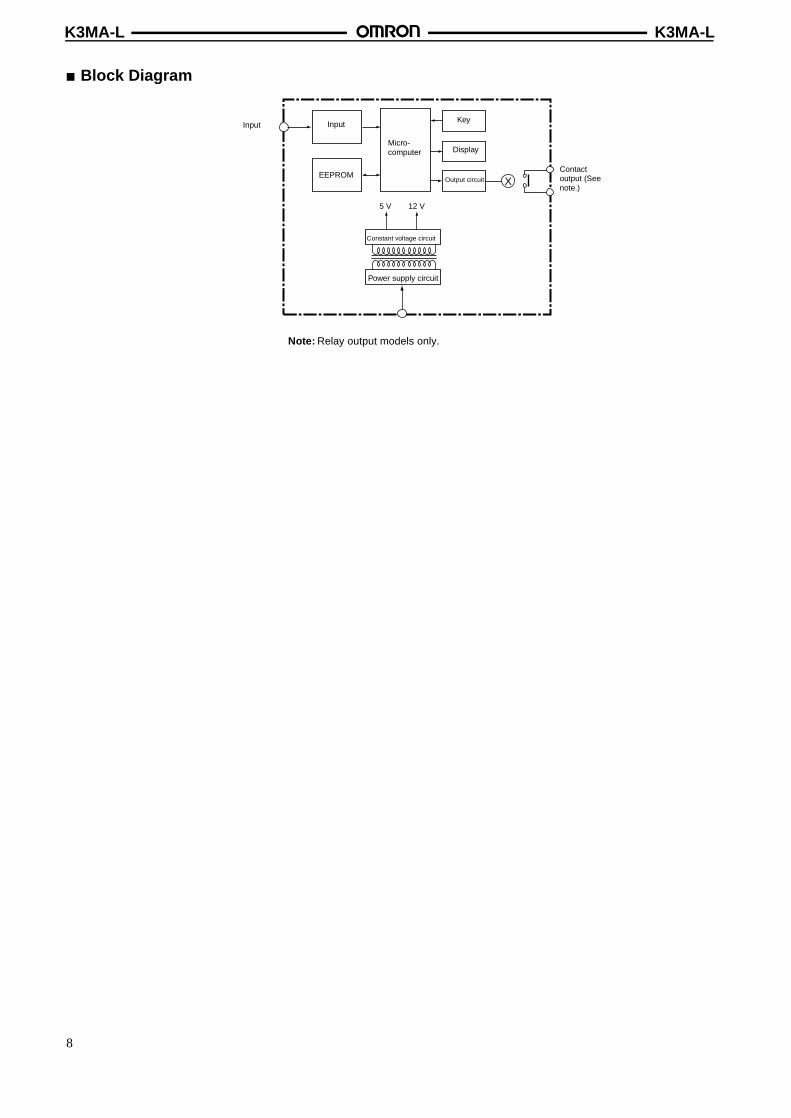
■ Block Diagram
Note: Relay output models only.
XEEPROM
5 V 12 V
Input Input
Micro-computer
Key
Display
Output circuit
Constant voltage circuit
Power supply circuit
Contact output (See note.)
8

K3MA-LK3MA-L
■ Levels“Level” refers to a grouping of parameters. The following table lists the operations that are possible in each of the levels, and the diagramtells how to move between levels. There are some parameters that are not displayed for certain models.
Note: The move-to-protect-level time can be set in the advanced-function setting level.
Level name Function Measurement
Protect Setting lockouts. Continue
Operation Displaying current values, and setting OUT 1 value. Continue
Adjustment Setting communications writing control. Continue
Initial setting Making initial settings of input type, output operating action, and other parameters.
Stopped
Advanced-function setting Setting average processing, display color settings, and other ad-vanced function parameters.
Stopped
Protect level
Operation level
Power ON
+Time set by user
1 s min. - 123.4
Flashing stops if key is released.
1 s min.
Initial setting level
Password "−169"1 s min.
Advanced-function setting level
Continue to press the key for 2 s min.Indicates change of level.
1 s min. (See note.)
Adjustment level
Less than 1 s
+
9

K3MA-LK3MA-L
■ Parameters
Operation level
Set one of these.
Current value
OUT1 value
OUT1upper-limit value
OUT1lower-limit value
Note: 1. Some parameters are not displayed for certain models.
2. The K3MA-L will stop measurement if the level is changed to the initial setting level or the advanced-function setting level.
3. If the input range is changed, some parameters are set to default values. Therefore, set the input range first.
4. Settings displayed in reversed colors are initial settings.
Power ON
∼
∼
∼
∼ ∼0
Adjustment level
Press Level Key
Press Level Key
for less than 1 s.
for less than 1 s.
Temperature input shiftFor models with the comparative output function
MODE
MODE
MODE
MODE
10
K3MA-LK3MA-L
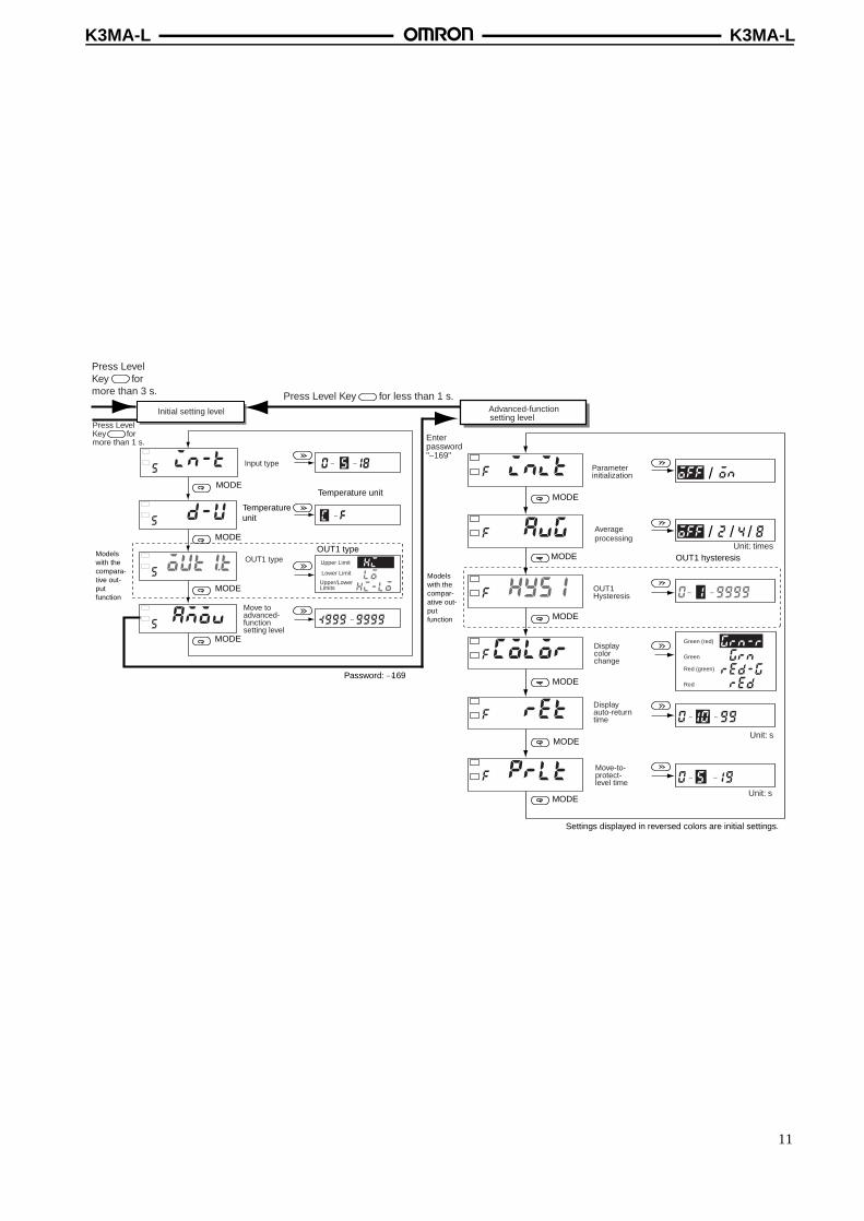
Enter password "−169"
Unit: times
Unit: s
Input type
OUT1 type
Move to advanced- function setting level
Parameter initialization
Averageprocessing
OUT1 Hysteresis
Display color change
Display auto-return time
Move-to-protect-level time
Green (red)
Green
Red (green)
Red
Upper Limit
Lower Limit
Upper/Lower Limits
Press Level Key for more than 1 s.
Press Level Key for less than 1 s.Initial setting level Advanced-function
setting level
Press Level Key for more than 3 s.
∼
∼
∼ ∼
∼∼
/
/
/ /
∼∼
∼∼
Unit: s
MODE
MODE
MODE
MODE
MODE
Temperature unit
MODE
MODE
MODE
MODE
MODE
Temperature unit
OUT1 type
Password: �169
Models with the compara-tive out-put function
Models with the compar-ative out-put function
OUT1 hysteresis
Settings displayed in reversed colors are initial settings.
11
K3MA-LK3MA-L
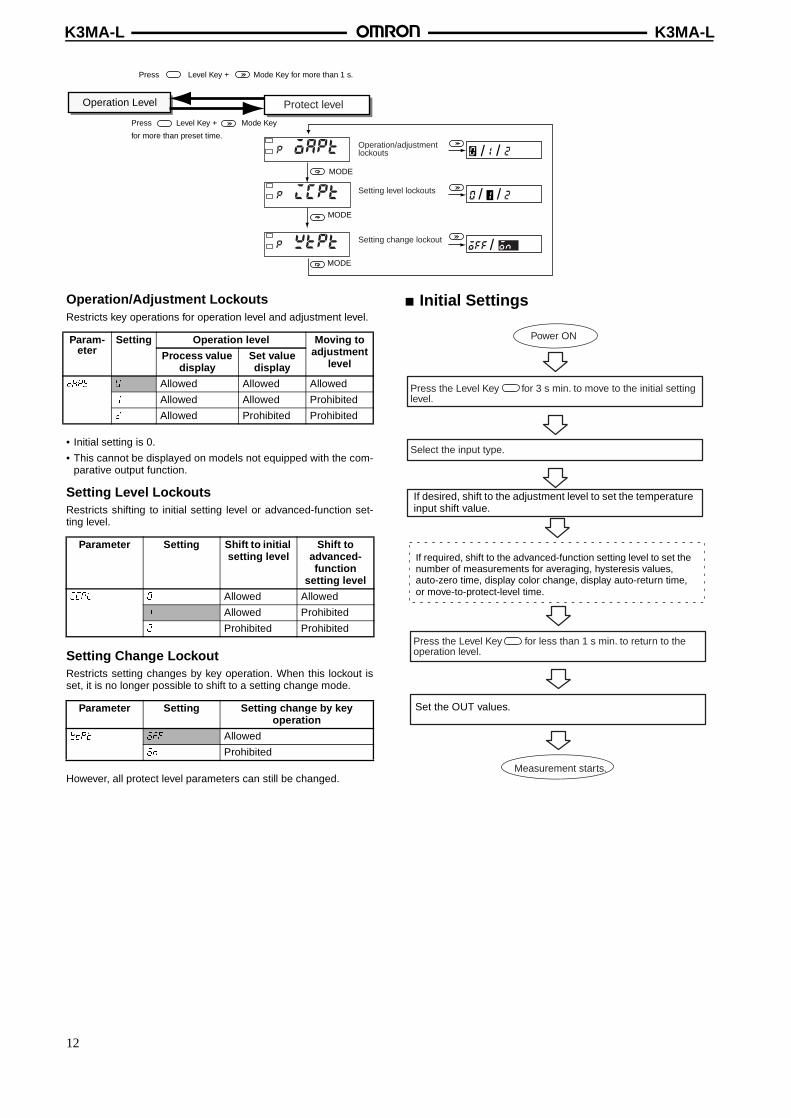
Operation/Adjustment LockoutsRestricts key operations for operation level and adjustment level.
• Initial setting is 0.
• This cannot be displayed on models not equipped with the com-parative output function.
Setting Level LockoutsRestricts shifting to initial setting level or advanced-function set-ting level.
Setting Change LockoutRestricts setting changes by key operation. When this lockout isset, it is no longer possible to shift to a setting change mode.
However, all protect level parameters can still be changed.
■ Initial Settings
Operation/adjustment lockouts
Setting level lockouts
Setting change lockout
/ /
/ /
/
Protect level
MODE
MODE
MODE
Operation Level
Press Level Key + Mode Key for more than 1 s.
Press Level Key + Mode Key
for more than preset time.
Param-eter
Setting Operation level Moving to adjustment
levelProcess value
displaySet value display
���� � Allowed Allowed Allowed
� Allowed Allowed Prohibited
� Allowed Prohibited Prohibited
Parameter Setting Shift to initial setting level
Shift to advanced-function
setting level
��� � Allowed Allowed
� Allowed Prohibited
� Prohibited Prohibited
Parameter Setting Setting change by key operation
���� ��� Allowed
�� Prohibited
Press the Level Key for 3 s min. to move to the initial setting level.
Select the input type.
Press the Level Key for less than 1 s min. to return to the operation level.
Measurement starts.
Power ON
If desired, shift to the adjustment level to set the temperature input shift value.
If required, shift to the advanced-function setting level to set the number of measurements for averaging, hysteresis values, auto-zero time, display color change, display auto-return time, or move-to-protect-level time.
Set the OUT values.
12

K3MA-LK3MA-L
■ Setting Example
Initial SettingsThe settings for the following example are shown here.
Example: Monitoring the temperature of an industrial furnace
Here, the temperature inside the furnace is to be displayed in cen-tigrade (�C).Temperature sensor: E52-PR Thermocouple, Measurementrange: 0 to 1,400�C.
1. Set the K3MA-L input type to the thermocouple R inputrange.Parameter: ��� (input type), Setting value: ��
2. Select centigrade (�C) as the temperature unit.Parameter: ��� (temperature unit), Setting value: �
If you are using a comparative output model, make the setting asdesired.
■ Application Examples
MAX/MIN LEVEL SHIFTMODE UP
1
SV
MaxMin
Industrial furnace
K3MA-L-C AC100-240V
E52-PR Thermocouple
K3MA-L
K3MA-L
E5EN
K3MA-L
Monitoring the temperature of an industrial furnace
Sending a temperature alarm for molding equipment
Monitoring the bearing temperature for a generator motor
Industrial furnace
PID control
Molding equipmentAlarm output
Generator motor
Alarm output
• Monitoring the temperature of an indus-trial furnace/sintering furnace.
• Monitoring/alarm function for disinfect-ing equipment.
• Monitoring (failsafe checking) abnormaltemperatures in molding equipment.
• Monitoring the liquid temperature forcleaning devices.
• Monitoring temperature rises in electricpower generating facilities.
• Inspecting temperatures in machinesand devices.
13

K3MA-LK3MA-L
Dimensions
Optional Parts (Order Separately)
Installation1. Insert the K3MA-L into the panel cut-out hole.
2. For a waterproof installation, insert the rubber gasket ontothe body of the K3MA-L.
3. Fit the adaptor into the grooves on the left and right sides ofthe rear case, then push it until it contacts the panel tosecure the K3MA-L.
■ Wiring Precautions• Use crimp terminals.• Tighten the terminal screws to a torque of approximately 0.5
Nm.• To avoid the influence of noise, route signal lines and power lines
separately.
■ Wiring• Use the following M3 crimp terminals.
■ Unit Markings (Provided)• The unit markings are not attached to the K3MA-L. Select the de-
sired markings from the provided sheet.
Note: For scales and gauges, use the unit markings that arespecified by the relevant laws or regulations.
Name Shape Model
Splash-proof Soft Cover K32-49SC
Hard Cover K32-49HC
ABCDE
UPSHIFTMODELEVELMAX/MIN
80
44.848
96
1.312
8597
101.291
120 min.
75 min.
45 +0.5 0
92+0.5 0
14.2 mm
7.6 mm
Finger protective cover (provided)
Main indicator character size
Panel cut-out
5.8 mm max.
5.8 mm max.
14

K3MA-LK3MA-L
Precautions !Caution
Do not touch the terminals while the power is being supplied.Doing so may result in electric shock.
!CautionDo not disassemble the product or touch the internal compo-nents of the product while the power is being supplied. Doingso may result in electric shock.
!CautionDo not allow pieces of metal or wire clippings to enter the prod-uct. Doing so may result in electric shock, fire, or malfunction.
!CautionPerform correct settings for the product according to the controlapplication. Failure to do so may cause unexpected operation,resulting in damage to the product or injury.
!CautionTake safety measures, such as installing a separate monitoringsystem, to ensure safety even if the product fails. Product fail-ure may prevent comparative outputs from being generated,resulting in serious accidents.
Observe the following precautions to ensure safety.
1. Maintain the power supply voltage within the range speci-fied in the specifications.
2. Maintain the load within the ratings specified in the specifi-cations.
3. Check each terminal for correct number and polarity beforeconnecting it. Incorrect or reverse connections may dam-age or burn out internal components in the product.
4. Tighten the terminal screws securely. The recommendedtightening torque is 0.43 to 0.58 N�m. Loose screws maycause fire or malfunction.
5. Do not connect anything to unused terminals.
6. Provide a switch or circuit breaker so that operators caneasily turn OFF the power supply when necessary. Alsoprovide appropriate indications of such devices.
7. Do not attempt to disassemble, repair, or modify the prod-uct.
8. Do not use the product where flammable or combustiblegases are present.
ApplicationGeneral Precautions
1. Do not use the product in the following locations:
• Locations subject to direct radiant heat from heatingequipment.
• Locations subject to exposure to water, oil, or chemicals.
• Locations subject to direct sunlight.
• Locations subject to dust or corrosive gases (particularly,sulfuric gas or ammonia gas).
• Locations subject to severe changes in temperature.
• Locations subject to icing or condensation.
• Locations subject to shock or vibration.
2. Do not block heat dissipation around the product, i.e., pro-vide sufficient space for heat dissipation.
3. Ensure that the rated voltage is reached within two secondsafter the power is turned ON.
4. Conduct aging for 15 minutes min. after power is turned ONfor correct measurement.
5. Do not touch the slit sections or terminals while the poweris being supplied to prevent the product from being affectedby static electricity.
6. Do not lay heavy objects on the product during use or stor-age. Doing so may deform or deteriorate the product.
7. Do not use paint thinner for cleaning. Use commerciallyavailable alcohol.
Mounting
• Mount the product to a panel that is 1 to 8 mm thick.
• Install the product in a horizontal position.
• Use crimp terminals that match screw sizes.
Noise Prevention
• Install the product as far as possible from devices that generatestrong, high-frequency fields (such as high-frequency welders orsewing machines) or surges.
• Install surge absorbers or noise filters on nearby devices thatgenerate noise (particularly motors, transformers, solenoids,magnet coils, and other devices that have a high inductancecomponent). Do not connect a surge absorber to the tempera-ture sensor input section of the K3MA-L.
• To prevent inductive noise, separate the terminal block wiring forthe product from high-voltage or high-current power lines. Do notroute the wiring for the product in parallel with or tie it in a bundlewith power lines.Take the following countermeasures against inductive noise ininput lines.
Temperature InputsSeparate the lead wire that connects the product with a temperaturesensor from the load line to prevent the product from being affected byinductive noise.
• When using a noise filter for the power supply, check for the volt-age and current and install it as close as possible to the Temper-ature Meter.
• Do not install the product near radios, television sets, or wirelessdevices. Doing so may cause reception interference.
Increasing Service Life
• Do not use the product in locations where the temperature or hu-midity exceeds the ratings or where condensation may occur.When installing the product in a panel, be sure that the temper-ature around the product (not the temperature around the panel)does not exceed the ratings. The product service life depends onthe ambient temperature. The higher the ambient temperature,the shorter the service life. To extend the product service life,lower the temperature inside the Temperature Meter.
• Use and store the product within the temperature and humidityranges given in the specifications. When gang-mounting Tem-perature Meters or arranging them vertically, heat generated bythe Temperature Meters will cause the internal temperature torise, reducing the service life. In such cases, consider forcedcooling methods, such as using a fan to circulate air around theTemperature Meters. Do not, however, allow only the terminalsto be cooled. Doing so will increase measurement error.
• The life of the output relays are greatly affected by the switchingcapacity and switching conditions. Use these relays within theirrated load and electrical life. The contacts may fuse or burn ifthey are used past their electrical life.
+
−
Line filter
Tempera-ture Meter
Surge absorber
Signal input
Power supply input
Power supply input
Tempera-ture Meter
15

K3MA-LK3MA-L
■ TroubleshootingWhen an error occurs, error details will be displayed on the main indicator. Confirm the error from the main indicator and take the appropri-ate countermeasures.
Level display Main indicator Error contents Countermeasures
Not lit ���� RAM memory error Repair is necessary.
Consult your OMRON sales rep-resentative.
� ���� EEPROM memory error When this error is displayed, press the Level Key for 3 sec-onds, and the settings will be re-stored to the factory settings.
If the error cannot be recovered, repair is necessary.
Consult your OMRON sales rep-resentative.
Not lit Flashes ����� Input error Confirm that the temperature sensor is correctly connected, and that there are no broken sig-nal lines to the temperature sen-sor.
If the condition does not return to normal, repair is necessary.
Consult your OMRON sales rep-resentative.
Not lit Flashes The measurement value after temperature input correction ex-ceeds 9999.
The temperature input correction value may be inappropriate.
Use the adjustment level to re-view the temperature input cor-rection value.
Not lit Flashes �� The measurement value after temperature input correction is lower than -1999.
The temperature input correction value may be inappropriate.
Use the adjustment level to re-view the temperature input cor-rection value.
In the interest of product improvement, specifications are subject to change without notice.
ALL DIMENSIONS SHOWN ARE IN MILLIMETERS.To convert millimeters into inches, multiply by 0.03937. To convert grams into ounces, multiply by 0.03527.
Cat. No. N109-E1-01
OMRON CorporationIndustrial Automation Company
Measuring and Supervisory Controls DepartmentShiokoji Horikawa, Shimogyo-kuKyoto, 600-8530 JapanTel: (81)75-344-7108/Fax: (81)75-344-7189
Printed in Japan1001-1M (1001) (B)
16