Embed Size (px)
Citation preview
K8AZ 2013 10m Yagi Design 1 August 12, 2013
K8AZ 2013 10 Meter Yagi Design August 12, 2013 Greg Ordy, W8WWV
V1.01
This note describes the 5L 10m Yagi that was constructed for the TUP Tower at K8AZ in the summer of 2013. Several other notes exist with information leading up to this design.
AutoEZ Optimizer Before the project started, all of the available 10m Yagi’s with boom lengths around 24’ were modeled. The idea was that an appropriate design would be found in that set, and 24’ was estimated to be the boom length that could be constructed from reused materials. Right after the modeling was complete, and a week or two before the existing Yagi’s were taken off of the tower, I learned that Dan, AC6LA, had added an optimizer feature to his AutoEZ program. AutoEZ is a product that could be called a front end for EZNEC. The Auto part is a tip off that the general intent of the program is to automate the process of running EZNEC, and provide convenience and/or analysis. The optimizer is a powerful addition to the program. AutoEZ promotes what-if analysis, whereas EZNEC by itself is more about specific results for a specific model. Perhaps AutoEZ could also be called an automatic parameterized model builder and results analyzer (with an optimizer!). Dan based the optimizer on the Nelder-Mead algorithm. It is a local optimizer, not a global optimizer. I’ve been very impressed in seeing it chew through a number of antenna designs. What’s most impressive to me is that it doesn’t seem to get stuck in local solutions that really are easy to improve on if you just permute the initial conditions a bit. In general, the optimizer performs a few hundred runs of EZNEC per job, and based upon your computer speed, usually takes no more than a few minutes to complete. Since the optimizer can get trapped in local minimums, it is a good idea to explore the design space with a set of different initial conditions. This added effort usually provides insight into the operation of the antenna, and is well worth the additional time. AutoEZ will drive both NEC-2 and NEC-4 versions of EZNEC.
K8AZ 2013 10m Yagi Design 2 August 12, 2013
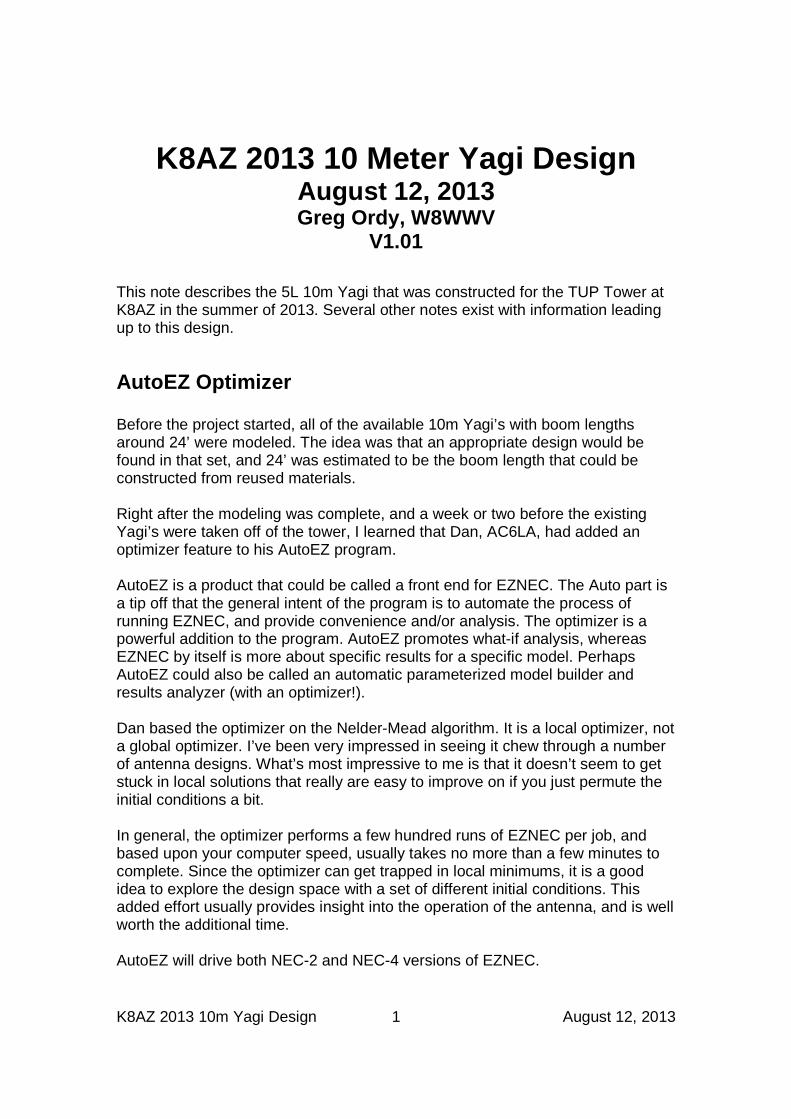
Modeling antennas in EZNEC involves filling up tables with numbers. Perhaps the most important table is the Wire table, where every wire in the model is described as two end points, a diameter, and a few more parameters. An end point is captured as three numbers; the X, Y, and Z coordinates in a standard orthogonal space. AutoEZ repeats the same interface. The difference is that the values can be variables and even formulas, not just boring old numbers. If this sounds a lot like a spreadsheet program, like Microsoft Excel, it should. AutoEZ is based upon Excel, with a lot of additional programming behind the curtain. As a quick example, here is the view of this antenna in EZNEC, with some added annotations.
Figure 1 – Yagi Orientation and Variables
The Z axis is the height above ground, which I set at 70’ for single 10m Yagi modeling. This is about 2 wavelengths above ground, and also the approximate middle point for the eventual stack of 4 Yagi’s. The Yagi boom runs down along the X axis. The reflector is anchored at the origin, running along the Y axis. The elements are at a constant X distance down the X axis, and straddle it, meaning that the tips on one end of an element are the same distance from the X axis as the tips on the other end.
K8AZ 2013 10m Yagi Design 3 August 12, 2013
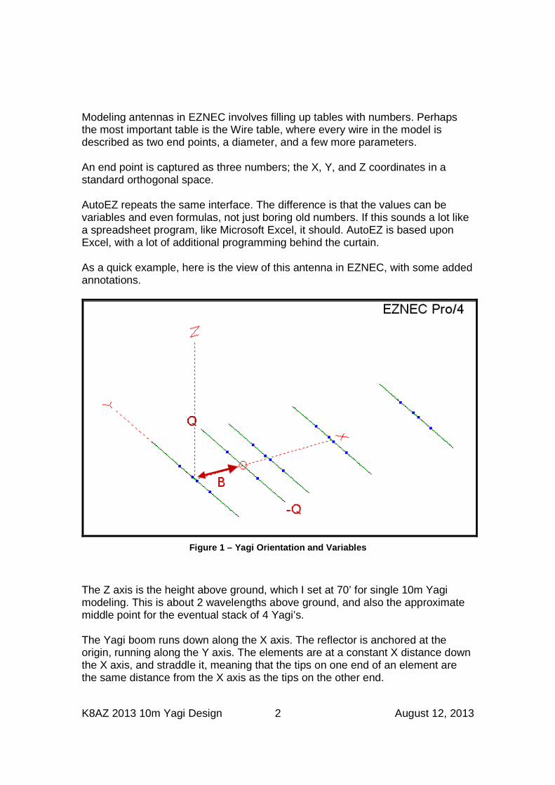
In the example, the distance from the reflector (REF) to the driven element (DE) is the variable B. The tips of the DE extend Q distance along the Y axis for one tip, and –Q for the other tip. B and Q are just convenient names, nothing special. Using the formula view in the program, the description of the DE appears as follows:
Figure 2 – AutoEZ Wire Table for the DE (formula vi ew)
I added the colored text and highlights for this example. There are three Wires in the DE description - more on that in a bit. In this model, the units are feet. The Z coordinate values are all 70, meaning 70’ off of the ground. Since the DE is parallel to the Y axis, all of the X coordinates for all three wires have the value B, and because this is Excel, the value in the cell is =B. This is the yellow highlight. The tips, in purple, are specified as –Q and Q (oops, =-Q and =Q). The diameters show up as 0.875” and 0.75”, and there are 7 segments per Wire. The wire numbers, W6, W7, and W8, are assigned by AutoEZ, and survive through to the EZNEC model. The other elements are described with the same approach, although they have more Wires because an additional tube diameter is used. At the end of the day, for a 5L Yagi, there are 4 spacing variables, such as B, and 5 tip length variables, such as Q. The initial and final values for the optimizer variables appear on a worksheet, and here is an example for this antenna.
K8AZ 2013 10m Yagi Design 4 August 12, 2013
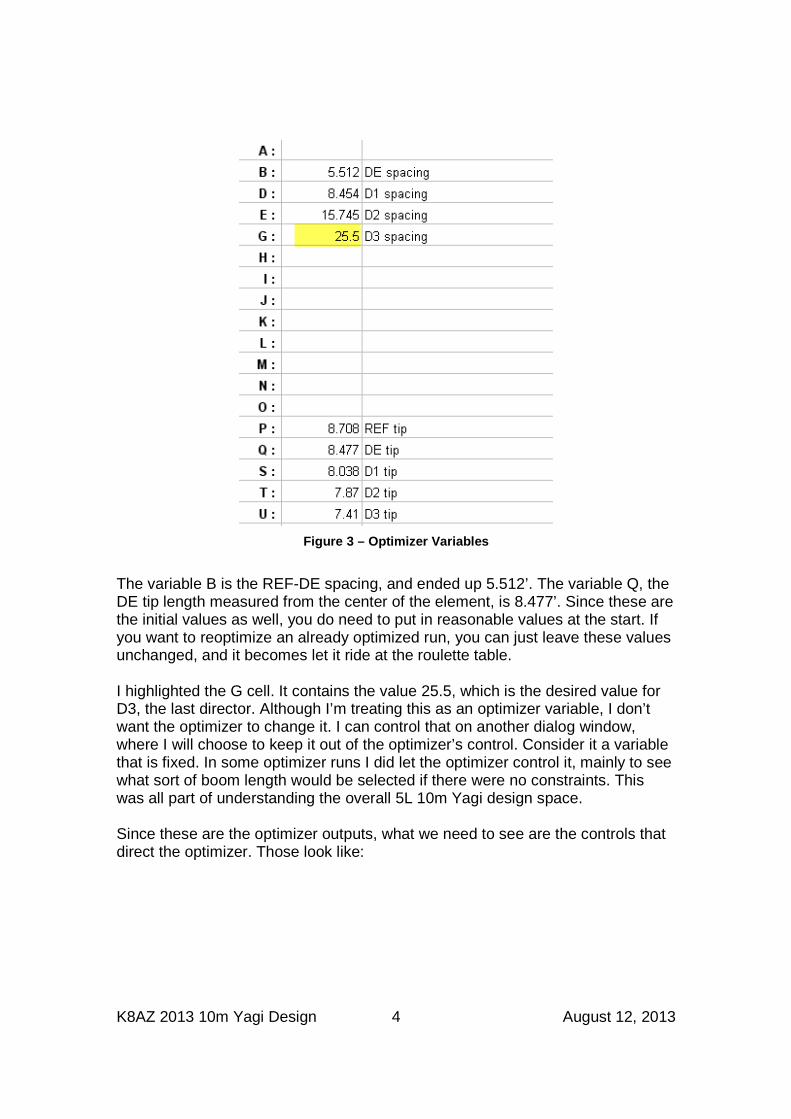
Figure 3 – Optimizer Variables
The variable B is the REF-DE spacing, and ended up 5.512’. The variable Q, the DE tip length measured from the center of the element, is 8.477’. Since these are the initial values as well, you do need to put in reasonable values at the start. If you want to reoptimize an already optimized run, you can just leave these values unchanged, and it becomes let it ride at the roulette table. I highlighted the G cell. It contains the value 25.5, which is the desired value for D3, the last director. Although I’m treating this as an optimizer variable, I don’t want the optimizer to change it. I can control that on another dialog window, where I will choose to keep it out of the optimizer’s control. Consider it a variable that is fixed. In some optimizer runs I did let the optimizer control it, mainly to see what sort of boom length would be selected if there were no constraints. This was all part of understanding the overall 5L 10m Yagi design space. Since these are the optimizer outputs, what we need to see are the controls that direct the optimizer. Those look like:
K8AZ 2013 10m Yagi Design 5 August 12, 2013
Figure 4 – Optimizer Controls
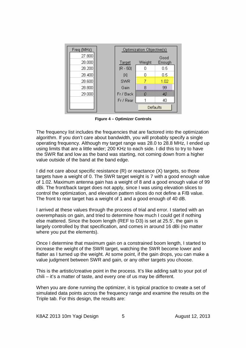
The frequency list includes the frequencies that are factored into the optimization algorithm. If you don’t care about bandwidth, you will probably specify a single operating frequency. Although my target range was 28.0 to 28.8 MHz, I ended up using limits that are a little wider; 200 KHz to each side. I did this to try to have the SWR flat and low as the band was starting, not coming down from a higher value outside of the band at the band edge. I did not care about specific resistance (R) or reactance (X) targets, so those targets have a weight of 0. The SWR target weight is 7 with a good enough value of 1.02. Maximum antenna gain has a weight of 8 and a good enough value of 99 dBi. The front/back target does not apply, since I was using elevation slices to control the optimization, and elevation pattern slices do not define a F/B value. The front to rear target has a weight of 1 and a good enough of 40 dB. I arrived at these values through the process of trial and error. I started with an overemphasis on gain, and tried to determine how much I could get if nothing else mattered. Since the boom length (REF to D3) is set at 25.5’, the gain is largely controlled by that specification, and comes in around 16 dBi (no matter where you put the elements). Once I determine that maximum gain on a constrained boom length, I started to increase the weight of the SWR target, watching the SWR become lower and flatter as I turned up the weight. At some point, if the gain drops, you can make a value judgment between SWR and gain, or any other targets you choose. This is the artistic/creative point in the process. It’s like adding salt to your pot of chili – it’s a matter of taste, and every one of us may be different. When you are done running the optimizer, it is typical practice to create a set of simulated data points across the frequency range and examine the results on the Triple tab. For this design, the results are:
K8AZ 2013 10m Yagi Design 6 August 12, 2013
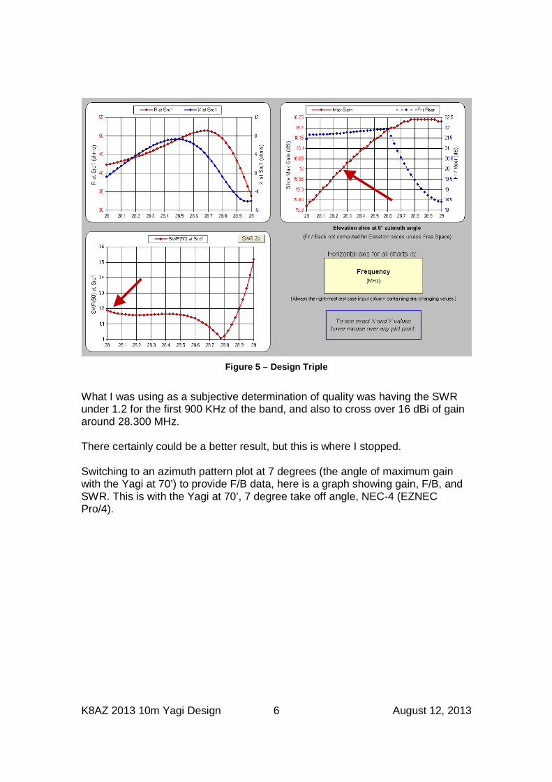
Figure 5 – Design Triple
What I was using as a subjective determination of quality was having the SWR under 1.2 for the first 900 KHz of the band, and also to cross over 16 dBi of gain around 28.300 MHz. There certainly could be a better result, but this is where I stopped. Switching to an azimuth pattern plot at 7 degrees (the angle of maximum gain with the Yagi at 70’) to provide F/B data, here is a graph showing gain, F/B, and SWR. This is with the Yagi at 70’, 7 degree take off angle, NEC-4 (EZNEC Pro/4).
K8AZ 2013 10m Yagi Design 7 August 12, 2013
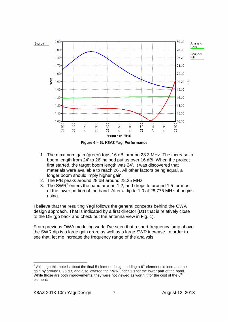
Figure 6 – 5L K8AZ Yagi Performance
1. The maximum gain (green) tops 16 dBi around 28.3 MHz. The increase in
boom length from 24’ to 26’ helped put us over 16 dBi. When the project first started, the target boom length was 24’. It was discovered that materials were available to reach 26’. All other factors being equal, a longer boom should imply higher gain.
2. The F/B peaks around 28 dB around 28.25 MHz. 3. The SWR1 enters the band around 1.2, and drops to around 1.5 for most
of the lower portion of the band. After a dip to 1.0 at 28.775 MHz, it begins rising.
I believe that the resulting Yagi follows the general concepts behind the OWA design approach. That is indicated by a first director (D1) that is relatively close to the DE (go back and check out the antenna view in Fig. 1). From previous OWA modeling work, I’ve seen that a short frequency jump above the SWR dip is a large gain drop, as well as a large SWR increase. In order to see that, let me increase the frequency range of the analysis.
1 Although this note is about the final 5 element design, adding a 6th element did increase the gain by around 0.25 dB, and also lowered the SWR under 1.1 for the lower part of the band. While those are both improvements, they were not viewed as worth it for the cost of the 6th element.
K8AZ 2013 10m Yagi Design 8 August 12, 2013
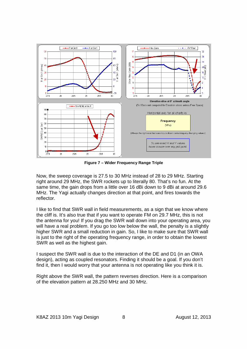
Figure 7 – Wider Frequency Range Triple
Now, the sweep coverage is 27.5 to 30 MHz instead of 28 to 29 MHz. Starting right around 29 MHz, the SWR rockets up to literally 80. That’s no fun. At the same time, the gain drops from a little over 16 dBi down to 9 dBi at around 29.6 MHz. The Yagi actually changes direction at that point, and fires towards the reflector. I like to find that SWR wall in field measurements, as a sign that we know where the cliff is. It’s also true that if you want to operate FM on 29.7 MHz, this is not the antenna for you! If you drag the SWR wall down into your operating area, you will have a real problem. If you go too low below the wall, the penalty is a slightly higher SWR and a small reduction in gain. So, I like to make sure that SWR wall is just to the right of the operating frequency range, in order to obtain the lowest SWR as well as the highest gain. I suspect the SWR wall is due to the interaction of the DE and D1 (in an OWA design), acting as coupled resonators. Finding it should be a goal. If you don’t find it, then I would worry that your antenna is not operating like you think it is. Right above the SWR wall, the pattern reverses direction. Here is a comparison of the elevation pattern at 28.250 MHz and 30 MHz.
K8AZ 2013 10m Yagi Design 9 August 12, 2013
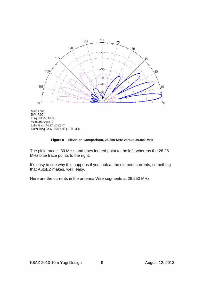
Figure 8 – Elevation Comparison, 28.250 MHz versus 30.000 MHz
The pink trace is 30 MHz, and does indeed point to the left, whereas the 28.25 MHz blue trace points to the right. It’s easy to see why this happens if you look at the element currents, something that AutoEZ makes, well, easy. Here are the currents in the antenna Wire segments at 28.250 MHz:
K8AZ 2013 10m Yagi Design 10 August 12, 2013
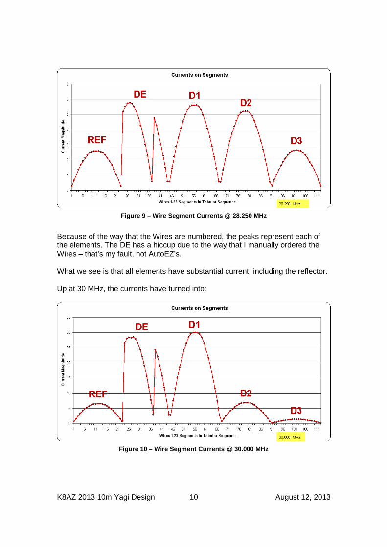
Figure 9 – Wire Segment Currents @ 28.250 MHz
Because of the way that the Wires are numbered, the peaks represent each of the elements. The DE has a hiccup due to the way that I manually ordered the Wires – that’s my fault, not AutoEZ’s. What we see is that all elements have substantial current, including the reflector. Up at 30 MHz, the currents have turned into:
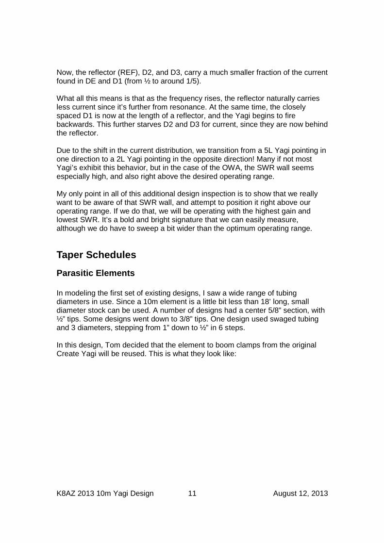
Figure 10 – Wire Segment Currents @ 30.000 MHz
K8AZ 2013 10m Yagi Design 11 August 12, 2013
Now, the reflector (REF), D2, and D3, carry a much smaller fraction of the current found in DE and D1 (from ½ to around 1/5). What all this means is that as the frequency rises, the reflector naturally carries less current since it’s further from resonance. At the same time, the closely spaced D1 is now at the length of a reflector, and the Yagi begins to fire backwards. This further starves D2 and D3 for current, since they are now behind the reflector. Due to the shift in the current distribution, we transition from a 5L Yagi pointing in one direction to a 2L Yagi pointing in the opposite direction! Many if not most Yagi’s exhibit this behavior, but in the case of the OWA, the SWR wall seems especially high, and also right above the desired operating range. My only point in all of this additional design inspection is to show that we really want to be aware of that SWR wall, and attempt to position it right above our operating range. If we do that, we will be operating with the highest gain and lowest SWR. It’s a bold and bright signature that we can easily measure, although we do have to sweep a bit wider than the optimum operating range.
Taper Schedules
Parasitic Elements In modeling the first set of existing designs, I saw a wide range of tubing diameters in use. Since a 10m element is a little bit less than 18’ long, small diameter stock can be used. A number of designs had a center 5/8” section, with ½” tips. Some designs went down to 3/8” tips. One design used swaged tubing and 3 diameters, stepping from 1” down to ½” in 6 steps. In this design, Tom decided that the element to boom clamps from the original Create Yagi will be reused. This is what they look like:
K8AZ 2013 10m Yagi Design 12 August 12, 2013
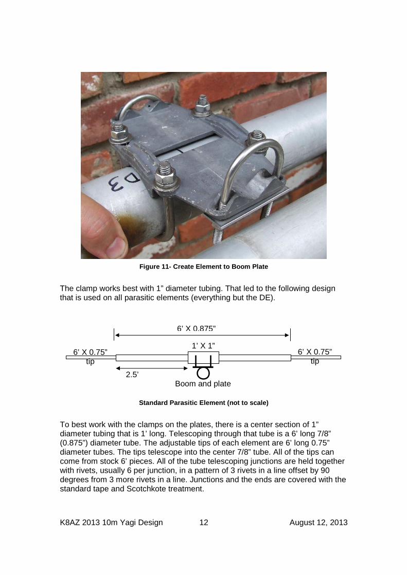
Figure 11- Create Element to Boom Plate
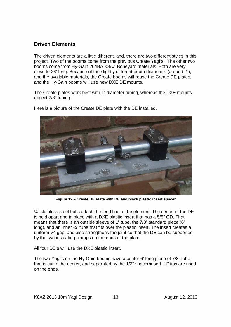
The clamp works best with 1” diameter tubing. That led to the following design that is used on all parasitic elements (everything but the DE).
Standard Parasitic Element (not to scale)
To best work with the clamps on the plates, there is a center section of 1” diameter tubing that is 1’ long. Telescoping through that tube is a 6’ long 7/8” (0.875”) diameter tube. The adjustable tips of each element are 6’ long 0.75” diameter tubes. The tips telescope into the center 7/8” tube. All of the tips can come from stock 6’ pieces. All of the tube telescoping junctions are held together with rivets, usually 6 per junction, in a pattern of 3 rivets in a line offset by 90 degrees from 3 more rivets in a line. Junctions and the ends are covered with the standard tape and Scotchkote treatment.
Boom and plate
1’ X 1”
6’ X 0.875”
6’ X 0.75” tip
6’ X 0.75” tip
2.5’
K8AZ 2013 10m Yagi Design 13 August 12, 2013
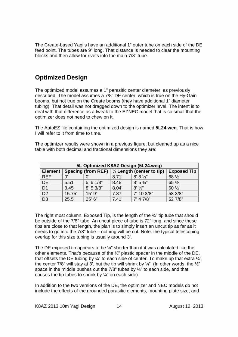
Driven Elements The driven elements are a little different, and, there are two different styles in this project. Two of the booms come from the previous Create Yagi’s. The other two booms come from Hy-Gain 204BA K8AZ Boneyard materials. Both are very close to 26’ long. Because of the slightly different boom diameters (around 2”), and the available materials, the Create booms will reuse the Create DE plates, and the Hy-Gain booms will use new DXE DE mounts. The Create plates work best with 1” diameter tubing, whereas the DXE mounts expect 7/8” tubing. Here is a picture of the Create DE plate with the DE installed.
Figure 12 – Create DE Plate with DE and black plast ic insert spacer
¼” stainless steel bolts attach the feed line to the element. The center of the DE is held apart and in place with a DXE plastic insert that has a 5/8” OD. That means that there is an outside sleeve of 1” tube, the 7/8” standard piece (6’ long), and an inner ¾” tube that fits over the plastic insert. The insert creates a uniform ½” gap, and also strengthens the joint so that the DE can be supported by the two insulating clamps on the ends of the plate. All four DE’s will use the DXE plastic insert. The two Yagi’s on the Hy-Gain booms have a center 6’ long piece of 7/8” tube that is cut in the center, and separated by the 1/2” spacer/insert. ¾” tips are used on the ends.
K8AZ 2013 10m Yagi Design 14 August 12, 2013
The Create-based Yagi’s have an additional 1” outer tube on each side of the DE feed point. The tubes are 9” long. That distance is needed to clear the mounting blocks and then allow for rivets into the main 7/8” tube.
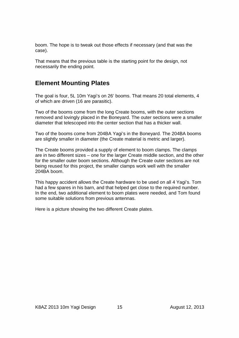
Optimized Design The optimized model assumes a 1” parasitic center diameter, as previously described. The model assumes a 7/8” DE center, which is true on the Hy-Gain booms, but not true on the Create booms (they have additional 1” diameter tubing). That detail was not dragged down to the optimizer level. The intent is to deal with that difference as a tweak to the EZNEC model that is so small that the optimizer does not need to chew on it. The AutoEZ file containing the optimized design is named 5L24.weq . That is how I will refer to it from time to time. The optimizer results were shown in a previous figure, but cleaned up as a nice table with both decimal and fractional dimensions they are:
5L Optimized K8AZ Design (5L24.weq) Element Spacing (from REF) ½ Length (center to tip) Exposed Tip REF 0’ 0’ 8.71’ 8’ 8 ½” 68 ½” DE 5.51’ 5’ 6 1/8” 8.48’ 8’ 5 ¾” 65 ½” D1 8.45’ 8’ 5 3/8” 8.04’ 8’ ½” 60 ½” D2 15.75’ 15’ 9” 7.87’ 7’ 10 3/8” 58 3/8” D3 25.5’ 25’ 6” 7.41’ 7’ 4 7/8” 52 7/8”
The right most column, Exposed Tip, is the length of the ¾” tip tube that should be outside of the 7/8” tube. An uncut piece of tube is 72” long, and since these tips are close to that length, the plan is to simply insert an uncut tip as far as it needs to go into the 7/8” tube – nothing will be cut. Note: the typical telescoping overlap for this size tubing is usually around 3”. The DE exposed tip appears to be ¼” shorter than if it was calculated like the other elements. That’s because of the ½” plastic spacer in the middle of the DE, that offsets the DE tubing by ¼” to each side of center. To make up that extra ¼”, the center 7/8” will stay at 3’, but the tip will shrink by ¼”. (In other words, the ½” space in the middle pushes out the 7/8” tubes by ¼” to each side, and that causes the tip tubes to shrink by ¼” on each side) In addition to the two versions of the DE, the optimizer and NEC models do not include the effects of the grounded parasitic elements, mounting plate size, and
K8AZ 2013 10m Yagi Design 15 August 12, 2013
boom. The hope is to tweak out those effects if necessary (and that was the case). That means that the previous table is the starting point for the design, not necessarily the ending point.
Element Mounting Plates The goal is four, 5L 10m Yagi’s on 26’ booms. That means 20 total elements, 4 of which are driven (16 are parasitic). Two of the booms come from the long Create booms, with the outer sections removed and lovingly placed in the Boneyard. The outer sections were a smaller diameter that telescoped into the center section that has a thicker wall. Two of the booms come from 204BA Yagi’s in the Boneyard. The 204BA booms are slightly smaller in diameter (the Create material is metric and larger). The Create booms provided a supply of element to boom clamps. The clamps are in two different sizes – one for the larger Create middle section, and the other for the smaller outer boom sections. Although the Create outer sections are not being reused for this project, the smaller clamps work well with the smaller 204BA boom. This happy accident allows the Create hardware to be used on all 4 Yagi’s. Tom had a few spares in his barn, and that helped get close to the required number. In the end, two additional element to boom plates were needed, and Tom found some suitable solutions from previous antennas. Here is a picture showing the two different Create plates.
K8AZ 2013 10m Yagi Design 16 August 12, 2013
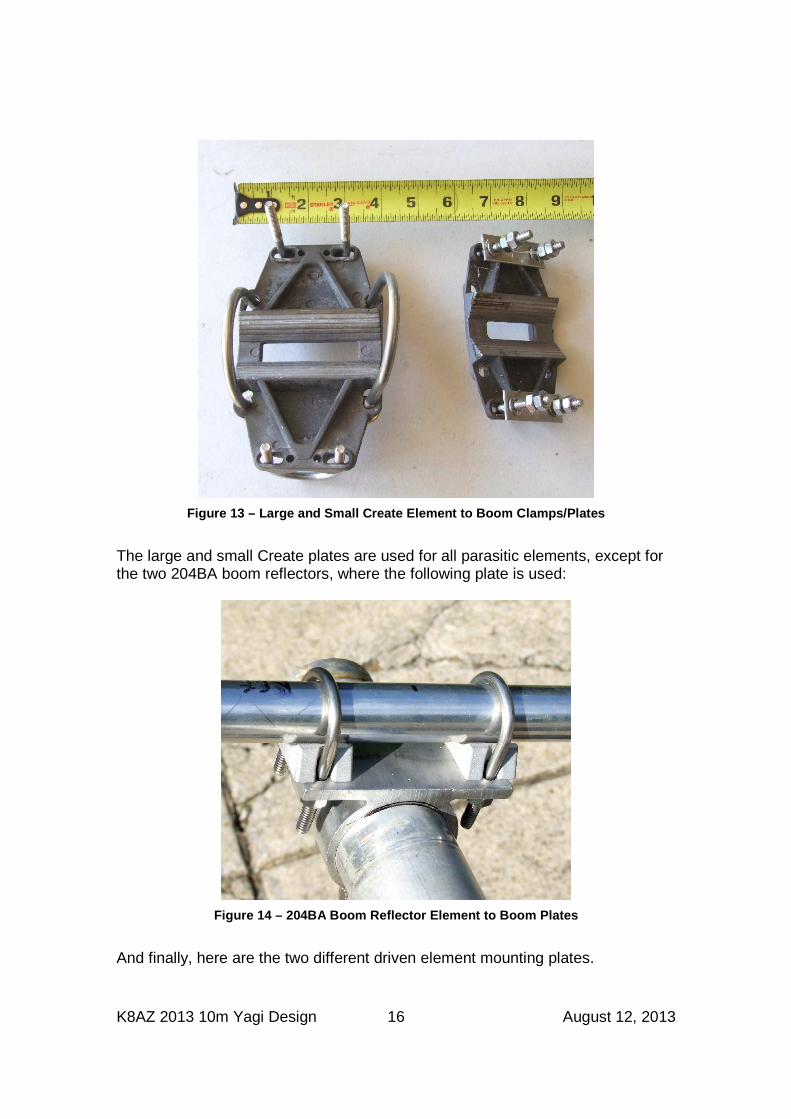
Figure 13 – Large and Small Create Element to Boom Clamps/Plates
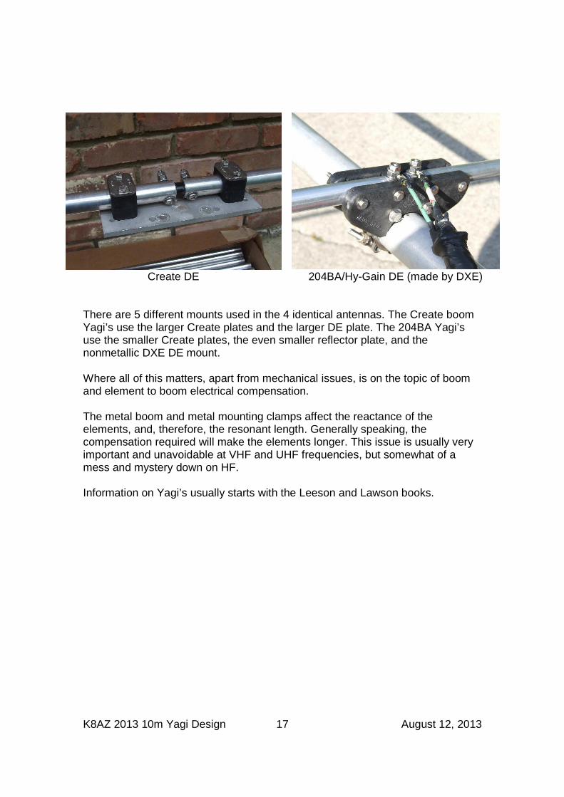
The large and small Create plates are used for all parasitic elements, except for the two 204BA boom reflectors, where the following plate is used:
Figure 14 – 204BA Boom Reflector Element to Boom Pl ates
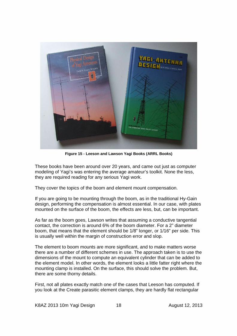
And finally, here are the two different driven element mounting plates.
K8AZ 2013 10m Yagi Design 17 August 12, 2013
Create DE 204BA/Hy-Gain DE (made by DXE)
There are 5 different mounts used in the 4 identical antennas. The Create boom Yagi’s use the larger Create plates and the larger DE plate. The 204BA Yagi’s use the smaller Create plates, the even smaller reflector plate, and the nonmetallic DXE DE mount. Where all of this matters, apart from mechanical issues, is on the topic of boom and element to boom electrical compensation. The metal boom and metal mounting clamps affect the reactance of the elements, and, therefore, the resonant length. Generally speaking, the compensation required will make the elements longer. This issue is usually very important and unavoidable at VHF and UHF frequencies, but somewhat of a mess and mystery down on HF. Information on Yagi’s usually starts with the Leeson and Lawson books.
K8AZ 2013 10m Yagi Design 18 August 12, 2013
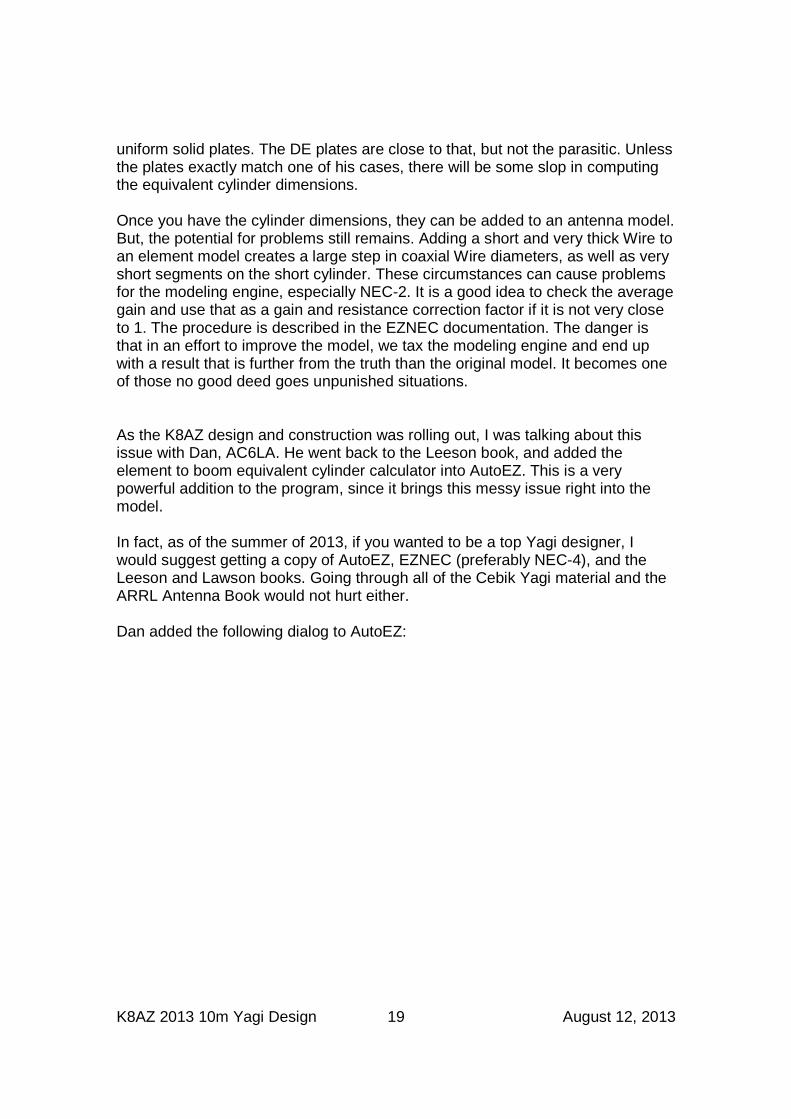
Figure 15 - Leeson and Lawson Yagi Books (ARRL Book s)
These books have been around over 20 years, and came out just as computer modeling of Yagi’s was entering the average amateur’s toolkit. None the less, they are required reading for any serious Yagi work. They cover the topics of the boom and element mount compensation. If you are going to be mounting through the boom, as in the traditional Hy-Gain design, performing the compensation is almost essential. In our case, with plates mounted on the surface of the boom, the effects are less, but, can be important. As far as the boom goes, Lawson writes that assuming a conductive tangential contact, the correction is around 6% of the boom diameter. For a 2” diameter boom, that means that the element should be 1/8” longer, or 1/16” per side. This is usually well within the margin of construction error and slop. The element to boom mounts are more significant, and to make matters worse there are a number of different schemes in use. The approach taken is to use the dimensions of the mount to compute an equivalent cylinder that can be added to the element model. In other words, the element looks a little fatter right where the mounting clamp is installed. On the surface, this should solve the problem. But, there are some thorny details. First, not all plates exactly match one of the cases that Leeson has computed. If you look at the Create parasitic element clamps, they are hardly flat rectangular
K8AZ 2013 10m Yagi Design 19 August 12, 2013
uniform solid plates. The DE plates are close to that, but not the parasitic. Unless the plates exactly match one of his cases, there will be some slop in computing the equivalent cylinder dimensions. Once you have the cylinder dimensions, they can be added to an antenna model. But, the potential for problems still remains. Adding a short and very thick Wire to an element model creates a large step in coaxial Wire diameters, as well as very short segments on the short cylinder. These circumstances can cause problems for the modeling engine, especially NEC-2. It is a good idea to check the average gain and use that as a gain and resistance correction factor if it is not very close to 1. The procedure is described in the EZNEC documentation. The danger is that in an effort to improve the model, we tax the modeling engine and end up with a result that is further from the truth than the original model. It becomes one of those no good deed goes unpunished situations. As the K8AZ design and construction was rolling out, I was talking about this issue with Dan, AC6LA. He went back to the Leeson book, and added the element to boom equivalent cylinder calculator into AutoEZ. This is a very powerful addition to the program, since it brings this messy issue right into the model. In fact, as of the summer of 2013, if you wanted to be a top Yagi designer, I would suggest getting a copy of AutoEZ, EZNEC (preferably NEC-4), and the Leeson and Lawson books. Going through all of the Cebik Yagi material and the ARRL Antenna Book would not hurt either. Dan added the following dialog to AutoEZ:
K8AZ 2013 10m Yagi Design 20 August 12, 2013
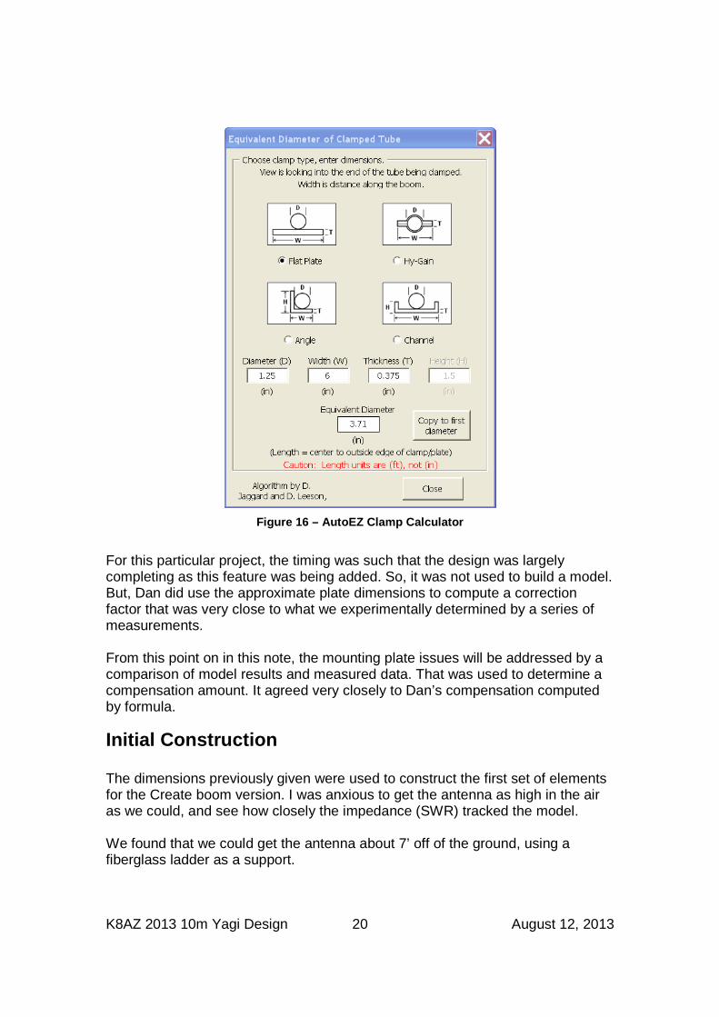
Figure 16 – AutoEZ Clamp Calculator
For this particular project, the timing was such that the design was largely completing as this feature was being added. So, it was not used to build a model. But, Dan did use the approximate plate dimensions to compute a correction factor that was very close to what we experimentally determined by a series of measurements. From this point on in this note, the mounting plate issues will be addressed by a comparison of model results and measured data. That was used to determine a compensation amount. It agreed very closely to Dan’s compensation computed by formula.
Initial Construction The dimensions previously given were used to construct the first set of elements for the Create boom version. I was anxious to get the antenna as high in the air as we could, and see how closely the impedance (SWR) tracked the model. We found that we could get the antenna about 7’ off of the ground, using a fiberglass ladder as a support.
K8AZ 2013 10m Yagi Design 21 August 12, 2013
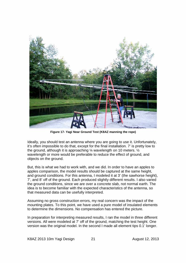
Figure 17- Yagi Near Ground Test (K8AZ manning the rope)
Ideally, you should test an antenna where you are going to use it. Unfortunately, it’s often impossible to do that, except for the final installation. 7’ is pretty low to the ground, although it is approaching ¼ wavelength on 10 meters. ½ wavelength or more would be preferable to reduce the effect of ground, and objects on the ground. But, this is what we had to work with, and we did. In order to have an apples to apples comparison, the model results should be captured at the same height, and ground conditions. For this antenna, I modeled it at 3’ (the sawhorse height), 7’, and 8’ off of the ground. Each produced slightly different results. I also varied the ground conditions, since we are over a concrete slab, not normal earth. The idea is to become familiar with the expected characteristics of the antenna, so that measured data can be usefully interpreted. Assuming no gross construction errors, my real concern was the impact of the mounting plates. To this point, we have used a pure model of insulated elements to determine the dimensions. No compensation has entered the picture. In preparation for interpreting measured results, I ran the model in three different versions. All were modeled at 7’ off of the ground, matching the test height. One version was the original model. In the second I made all element tips 0.1’ longer.
K8AZ 2013 10m Yagi Design 22 August 12, 2013
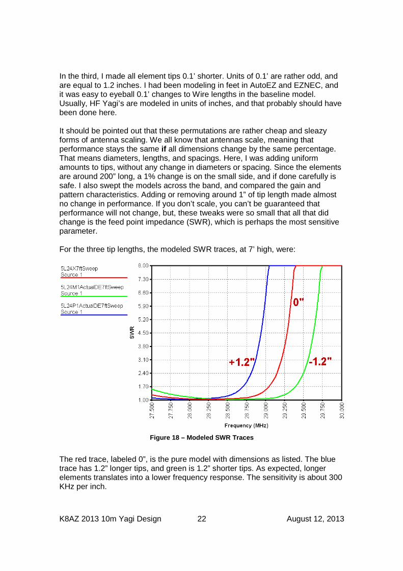
In the third, I made all element tips 0.1’ shorter. Units of 0.1’ are rather odd, and are equal to 1.2 inches. I had been modeling in feet in AutoEZ and EZNEC, and it was easy to eyeball 0.1’ changes to Wire lengths in the baseline model. Usually, HF Yagi’s are modeled in units of inches, and that probably should have been done here. It should be pointed out that these permutations are rather cheap and sleazy forms of antenna scaling. We all know that antennas scale, meaning that performance stays the same if all dimensions change by the same percentage. That means diameters, lengths, and spacings. Here, I was adding uniform amounts to tips, without any change in diameters or spacing. Since the elements are around 200” long, a 1% change is on the small side, and if done carefully is safe. I also swept the models across the band, and compared the gain and pattern characteristics. Adding or removing around 1” of tip length made almost no change in performance. If you don’t scale, you can’t be guaranteed that performance will not change, but, these tweaks were so small that all that did change is the feed point impedance (SWR), which is perhaps the most sensitive parameter. For the three tip lengths, the modeled SWR traces, at 7’ high, were:
Figure 18 – Modeled SWR Traces
The red trace, labeled 0”, is the pure model with dimensions as listed. The blue trace has 1.2” longer tips, and green is 1.2” shorter tips. As expected, longer elements translates into a lower frequency response. The sensitivity is about 300 KHz per inch.
K8AZ 2013 10m Yagi Design 23 August 12, 2013
NOTE: all tips on all elements changed length – not just the DE. Even though it might look like I’m trying to adjust the SWR through the DE, I’m really building up some baseline graphs for evaluating the element to boom plate compensation. All tips changed length because all of the elements have a mounting plate of approximately the same size. After the Yagi was hoisted to the 7’ level, Tom anchored the ladder while I made the same sweep measurement from 27.5 to 30 MHz using Tom’s AA54 antenna analyzer. This was a great unit for this job, since it displays a graph on its screen for immediate checking, and it can save data records for later recall. Tom emailed me the data files, and I then was able to marry them up with modeled data using the LBDXView program which is available on the ON4UN 5th edition CD. I should mention that it is important to clear the area around the Yagi. People and metal close to the antenna will make a difference. If they aren’t part of the model, remove them from the measurement. Although the quick visual check of the graph on the AA54 confirmed that we were in the ballpark, I was anxious to get back home to create a single graph of both measured and modeled data. This is where the rubber hits the road, so to speak. Before I present the measured data, I think we should be able to predict what we would like to see. Since the model does not include the mounting plates, the elements will be too short. That will kick up the frequency response, from the red trace in the previous plot towards the green. When I added the measured data to the previous plot I saw:
K8AZ 2013 10m Yagi Design 24 August 12, 2013
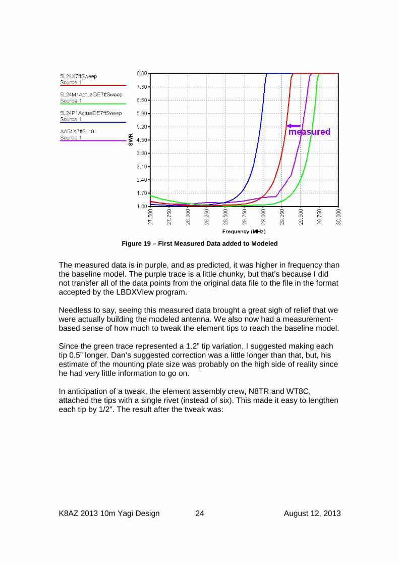
Figure 19 – First Measured Data added to Modeled
The measured data is in purple, and as predicted, it was higher in frequency than the baseline model. The purple trace is a little chunky, but that’s because I did not transfer all of the data points from the original data file to the file in the format accepted by the LBDXView program. Needless to say, seeing this measured data brought a great sigh of relief that we were actually building the modeled antenna. We also now had a measurement-based sense of how much to tweak the element tips to reach the baseline model. Since the green trace represented a 1.2” tip variation, I suggested making each tip 0.5” longer. Dan’s suggested correction was a little longer than that, but, his estimate of the mounting plate size was probably on the high side of reality since he had very little information to go on. In anticipation of a tweak, the element assembly crew, N8TR and WT8C, attached the tips with a single rivet (instead of six). This made it easy to lengthen each tip by 1/2”. The result after the tweak was:
K8AZ 2013 10m Yagi Design 25 August 12, 2013
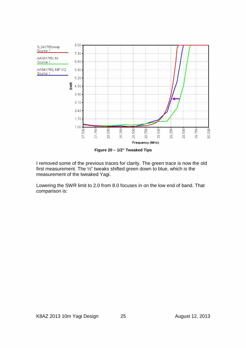
Figure 20 – 1/2” Tweaked Tips
I removed some of the previous traces for clarity. The green trace is now the old first measurement. The ½” tweaks shifted green down to blue, which is the measurement of the tweaked Yagi. Lowering the SWR limit to 2.0 from 8.0 focuses in on the low end of band. That comparison is:
K8AZ 2013 10m Yagi Design 26 August 12, 2013
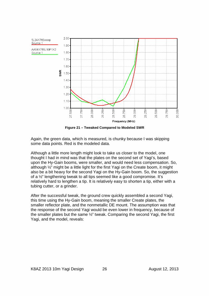
Figure 21 – Tweaked Compared to Modeled SWR
Again, the green data, which is measured, is chunky because I was skipping some data points. Red is the modeled data. Although a little more length might look to take us closer to the model, one thought I had in mind was that the plates on the second set of Yagi’s, based upon the Hy-Gain booms, were smaller, and would need less compensation. So, although ½” might be a little light for the first Yagi on the Create boom, it might also be a bit heavy for the second Yagi on the Hy-Gain boom. So, the suggestion of a ½” lengthening tweak to all tips seemed like a good compromise. It’s relatively hard to lengthen a tip. It is relatively easy to shorten a tip, either with a tubing cutter, or a grinder. After the successful tweak, the ground crew quickly assembled a second Yagi, this time using the Hy-Gain boom, meaning the smaller Create plates, the smaller reflector plate, and the nonmetallic DE mount. The assumption was that the response of the second Yagi would be even lower in frequency, because of the smaller plates but the same ½” tweak. Comparing the second Yagi, the first Yagi, and the model, reveals:
K8AZ 2013 10m Yagi Design 27 August 12, 2013
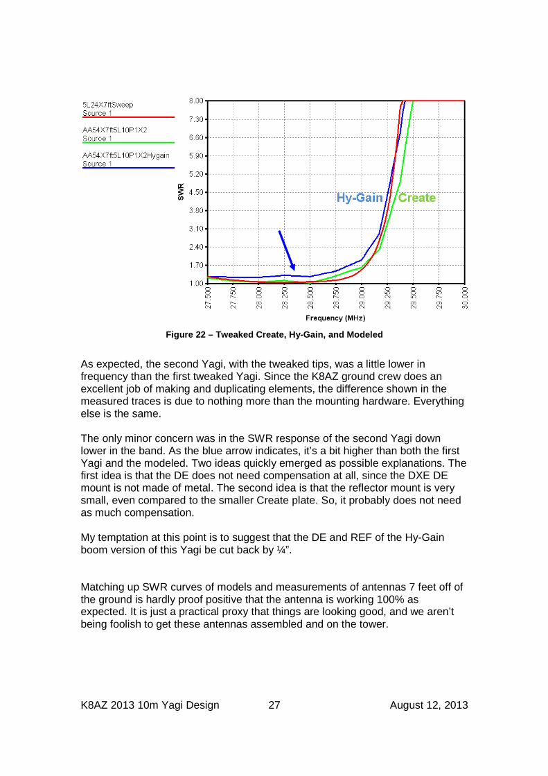
Figure 22 – Tweaked Create, Hy-Gain, and Modeled
As expected, the second Yagi, with the tweaked tips, was a little lower in frequency than the first tweaked Yagi. Since the K8AZ ground crew does an excellent job of making and duplicating elements, the difference shown in the measured traces is due to nothing more than the mounting hardware. Everything else is the same. The only minor concern was in the SWR response of the second Yagi down lower in the band. As the blue arrow indicates, it’s a bit higher than both the first Yagi and the modeled. Two ideas quickly emerged as possible explanations. The first idea is that the DE does not need compensation at all, since the DXE DE mount is not made of metal. The second idea is that the reflector mount is very small, even compared to the smaller Create plate. So, it probably does not need as much compensation. My temptation at this point is to suggest that the DE and REF of the Hy-Gain boom version of this Yagi be cut back by ¼”. Matching up SWR curves of models and measurements of antennas 7 feet off of the ground is hardly proof positive that the antenna is working 100% as expected. It is just a practical proxy that things are looking good, and we aren’t being foolish to get these antennas assembled and on the tower.
K8AZ 2013 10m Yagi Design 28 August 12, 2013
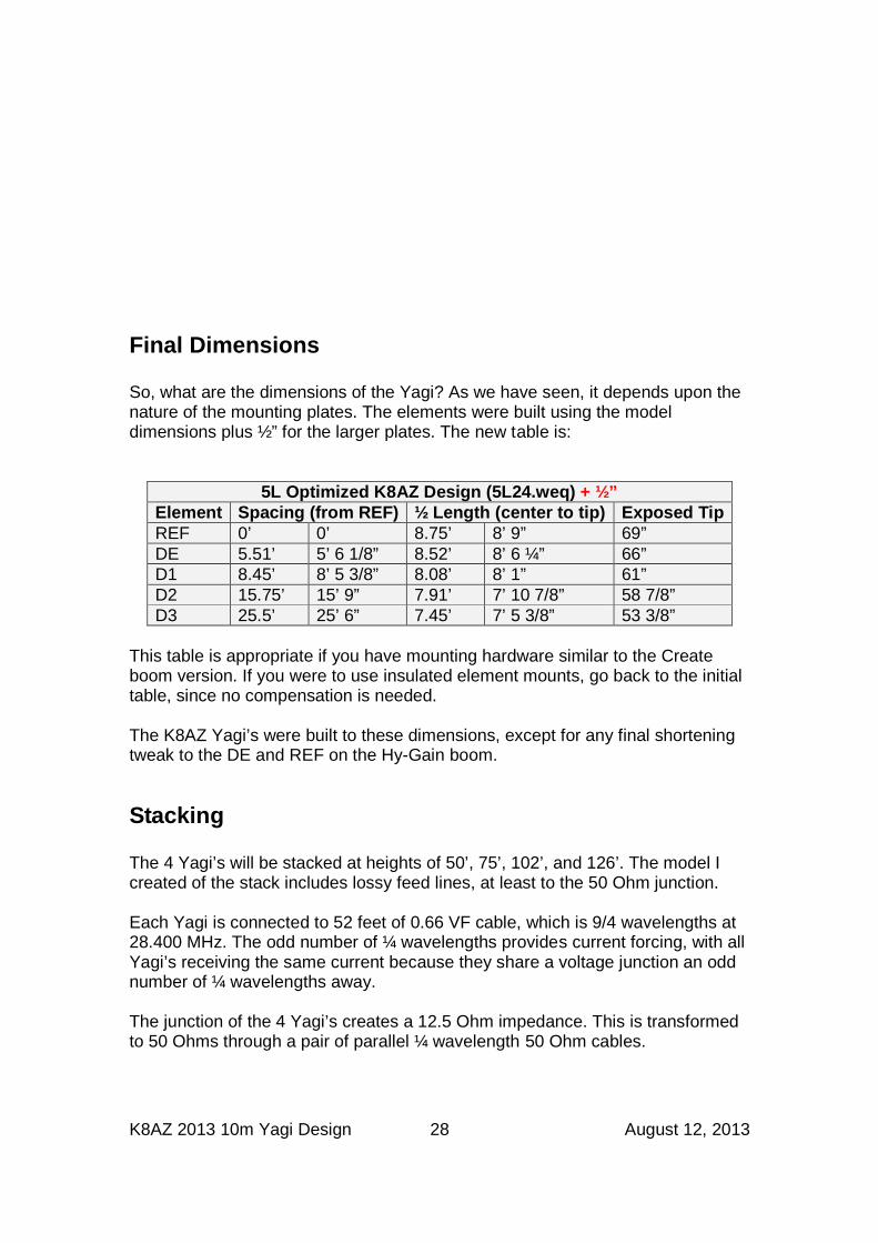
Final Dimensions So, what are the dimensions of the Yagi? As we have seen, it depends upon the nature of the mounting plates. The elements were built using the model dimensions plus ½” for the larger plates. The new table is:
5L Optimized K8AZ Design (5L24.weq) + ½” Element Spacing (from REF) ½ Length (center to tip) Exposed Tip REF 0’ 0’ 8.75’ 8’ 9” 69” DE 5.51’ 5’ 6 1/8” 8.52’ 8’ 6 ¼” 66” D1 8.45’ 8’ 5 3/8” 8.08’ 8’ 1” 61” D2 15.75’ 15’ 9” 7.91’ 7’ 10 7/8” 58 7/8” D3 25.5’ 25’ 6” 7.45’ 7’ 5 3/8” 53 3/8”
This table is appropriate if you have mounting hardware similar to the Create boom version. If you were to use insulated element mounts, go back to the initial table, since no compensation is needed. The K8AZ Yagi’s were built to these dimensions, except for any final shortening tweak to the DE and REF on the Hy-Gain boom.
Stacking The 4 Yagi’s will be stacked at heights of 50’, 75’, 102’, and 126’. The model I created of the stack includes lossy feed lines, at least to the 50 Ohm junction. Each Yagi is connected to 52 feet of 0.66 VF cable, which is 9/4 wavelengths at 28.400 MHz. The odd number of ¼ wavelengths provides current forcing, with all Yagi’s receiving the same current because they share a voltage junction an odd number of ¼ wavelengths away. The junction of the 4 Yagi’s creates a 12.5 Ohm impedance. This is transformed to 50 Ohms through a pair of parallel ¼ wavelength 50 Ohm cables.
K8AZ 2013 10m Yagi Design 29 August 12, 2013
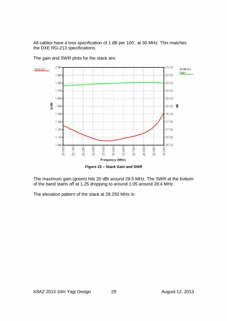
All cables have a loss specification of 1 dB per 100’, at 30 MHz. This matches the DXE RG-213 specifications. The gain and SWR plots for the stack are:
Figure 23 – Stack Gain and SWR
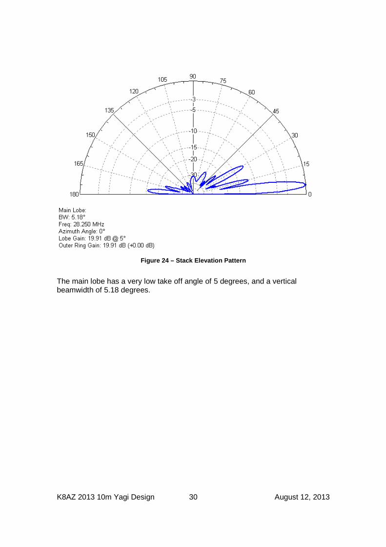
The maximum gain (green) hits 20 dBi around 28.5 MHz. The SWR at the bottom of the band starts off at 1.25 dropping to around 1.05 around 28.4 MHz. The elevation pattern of the stack at 28.250 MHz is:
K8AZ 2013 10m Yagi Design 30 August 12, 2013
Figure 24 – Stack Elevation Pattern
The main lobe has a very low take off angle of 5 degrees, and a vertical beamwidth of 5.18 degrees.