Embed Size (px)
Citation preview
Kabeldon cable accessories 1 - 420 kV 2009, edition 1

32 ABB Kabeldon2006 utgåva 1
Vi förbehåller oss rätten att ändra konstruktion och sortiment!
3
Introduction
Kabeldon 2009, edition 1 We reserve the right to alter the design and range of our products.
Introd
uction
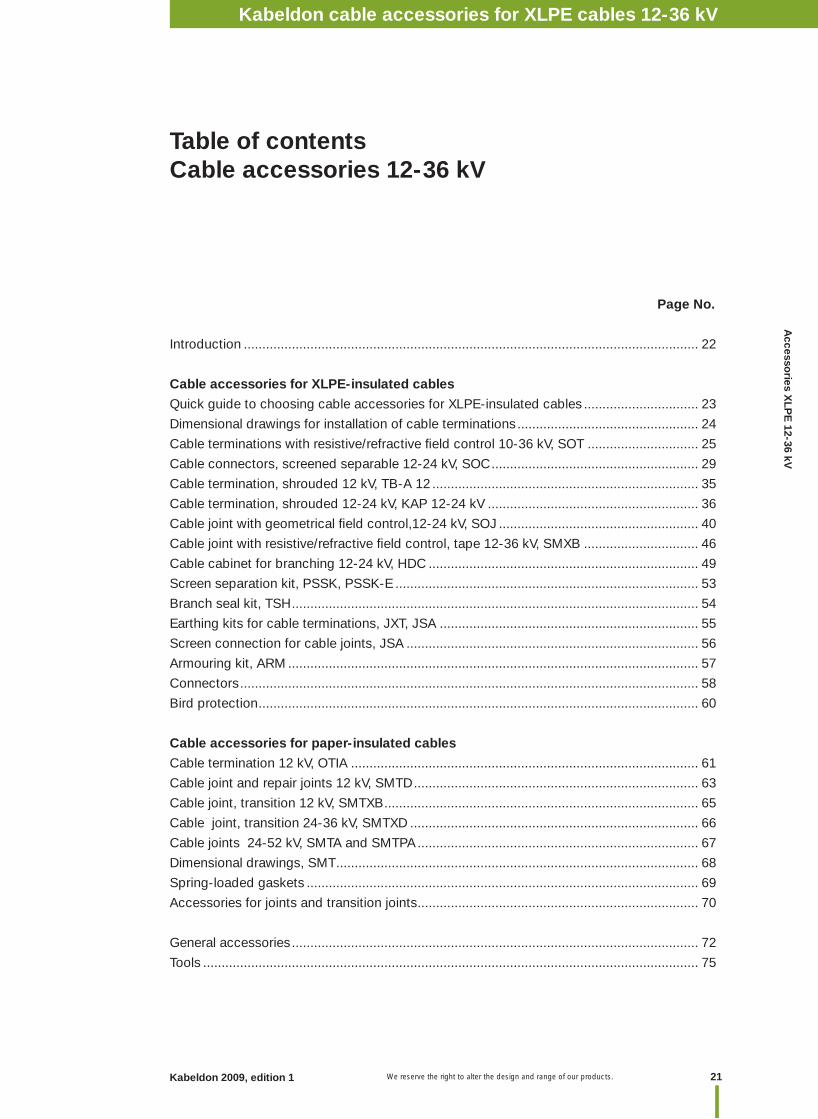
Table of contents
Page No.
Introduction ............................................................................................................................. 4
Fundamental technologies ...................................................................................................... 5
Reasons for choosing Kabeldon cable accessories ............................................................... 6
Standards ................................................................................................................................ 8
Reference illustrations ........................................................................................................... 10
Table of contents Kabeldon cable accessories ≤ 1 kV .......................................................... 11
Table of contents Kabeldon cable accessories 12-36 kV XLPE............................................ 21
Table of contents Kabeldon cable accessories 12-52 kV PILC ............................................ 61
Table of contents Kabeldon cable accessories 52-420 kV ................................................... 77
General accessories ........................................................................................................... 107
List of content in alphabetical order .................................................................................... 110
List of content by product category .................................................................................... 113
IntroductionIntroductionIntroductionIntroduction
4 Kabeldon 2009, edition 1
Introduction
We reserve the right to alter the design and range of our products.
Introduction
We work to create safe electrical distribution via power cable networks. To achieve this, we develop, manufacture and market a broad range of cable accessories, switching devices and enclosures.
Our main groups of customers are power supply companies, network companies, industrial companies and OEMs.
Our primary areas of expertise are electrical connections in cable systems and control of electrical fi eld. Our own testing plant is an important aid to product development.
CatalogueThe introductory pages show the most important products in their proper environment. The entire range is then presented in three main parts including product facts and ordering information in table form. ❑ Cable accessories 1 kV❑ Cable accessories 12-36 kV❑ Cable accessories 52-420 kV
An alphabetical list of contents and a list of contents by product category can be found in the end of this catalogue. The product catalogue is also available on CD and at our website. We reserve the right to alter the design and range of our products.
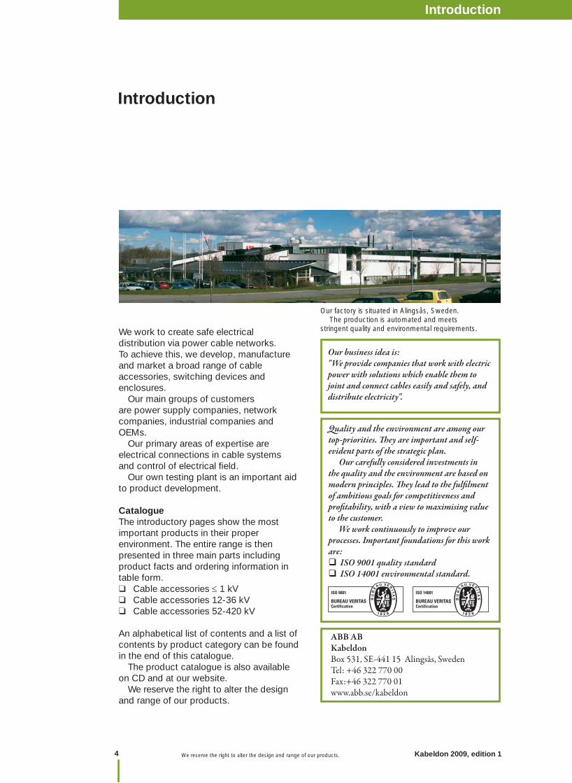
Our factory is situated in Alingsås, Sweden. The production is automated and meets stringent quality and environmental requirements.
Our business idea is: "We provide companies that work with electric power with solutions which enable them to joint and connect cables easily and safely, and distribute electricity".
ABB ABKabeldonBox 531, SE-441 15 Alingsås, SwedenTel: +46 322 770 00Fax:+46 322 770 01www.abb.se/kabeldon
Quality and the environment are among our top-priorities. Th ey are important and self-evident parts of the strategic plan. Our carefully considered investments in the quality and the environment are based on modern principles. Th ey lead to the fulfi lment of ambitious goals for competitiveness and profi tability, with a view to maximising value to the customer. We work continuously to improve our processes. Important foundations for this work are: ISO 9001 quality standard ISO 14001 environmental standard.
5
Introduction
Kabeldon 2009, edition 1 We reserve the right to alter the design and range of our products.
Introd
uction
We work on the basis of four fundamental technologies within which we have accumulated substantial expertise over many years.
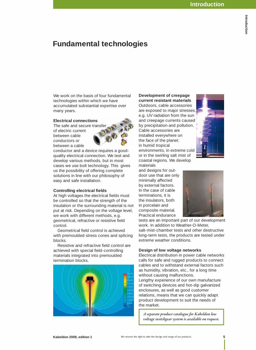
Electrical connections The safe and secure transfer of electric current between cable conductors or between a cable conductor and a device requires a good-quality electrical connection. We test and develop various methods, but in most cases we use bolt technology. This gives us the possibility of offering complete solutions in line with our philosophy of easy and safe installation.
Controlling electrical fi eldsAt high voltages the electrical fi elds must be controlled so that the strength of the insulation or the surrounding material is not put at risk. Depending on the voltage level, we work with different methods, e.g. geometrical, refractive or resistive fi eld control. Geometrical fi eld control is achieved with premoulded stress cones and splicing blocks. Resistive and refractive fi eld control are achieved with special fi eld-controlling materials integrated into premoulded termination blocks.
Fundamental technologies
Development of creepage current resistant materialsOutdoors, cable accessories are exposed to major stresses, e.g. UV radiation from the sun and creepage currents caused by precipitation and pollution. Cable accessories are installed everywhere on the face of the planet: in humid tropical environments, in extreme cold or in the swirling salt mist of coastal regions. We develop materials and designs for out-door use that are only minimally affected by external factors. In the case of cable terminations, it is the insulators, both in porcelain and composite material. Practical endurance tests are an important part of our development work. In addition to Weather-O-Meter, salt-mist-chamber tests and other destructive long-term tests, the products are tested under extreme weather conditions.
Design of low voltage networksElectrical distribution in power cable networks calls for safe and rugged products to connect cables and to withstand external factors such as humidity, vibration, etc., for a long time without causing malfunctions.
Lengthy experience of our own manufacture of switching devices and hot-dip galvanized enclosures, as well as good customer relations, means that we can quickly adapt product development to suit the needs of the market.
A separate product catalogue for Kabeldon low voltage switchgear system is available on request.
IntroductionIntroductionIntroductionIntroduction
6 Kabeldon 2009, edition 1
Introduction
We reserve the right to alter the design and range of our products.
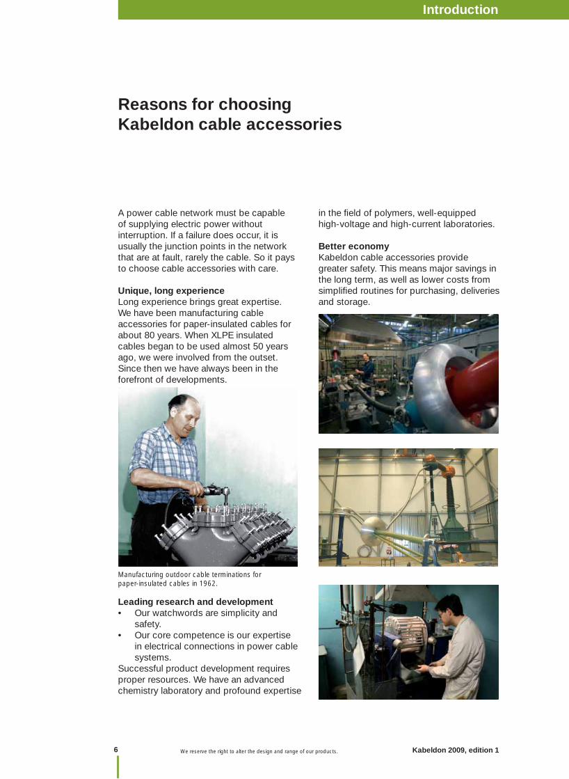
A power cable network must be capable of supplying electric power without interruption. If a failure does occur, it is usually the junction points in the network that are at fault, rarely the cable. So it pays to choose cable accessories with care.
Unique, long experienceLong experience brings great expertise.We have been manufacturing cable accessories for paper-insulated cables for about 80 years. When XLPE insulated cables began to be used almost 50 years ago, we were involved from the outset. Since then we have always been in the forefront of developments.
Leading research and developmentOur watchwords are simplicity and • safety.Our core competence is our expertise • in electrical connections in power cable systems.
Successful product development requires proper resources. We have an advanced chemistry laboratory and profound expertise
Reasons for choosing Kabeldon cable accessories
Manufacturing outdoor cable terminations for paper-insulated cables in 1962.
in the fi eld of polymers, well-equipped high-voltage and high-current laboratories. Better economyKabeldon cable accessories provide greater safety. This means major savings in the long term, as well as lower costs from simplifi ed routines for purchasing, deliveries and storage.

7
Introduction
Kabeldon 2009, edition 1 We reserve the right to alter the design and range of our products.
Introd
uction
Professional trainingThe technology of cables and their installation is constantly developing. We offer broad-based training in cable technology and cable accessories. Our instructors also take part in our development projects, so you can be sure that they have access to the latest technology. We arrange training programmes and practical exercises in the assembly of cable accessories up to 420 kV. All course participants will receive a diploma or a training certifi cate after passing a theoretical and practical test. If you would like to know more about the courses, please contact our training department.

IntroductionIntroductionIntroductionIntroduction
8 Kabeldon 2009, edition 1
Introduction
We reserve the right to alter the design and range of our products.
Standards
Tests in the high voltage laboratory.
Defi nition of voltagesCables and cable accessories are classifi ed according to the voltages at which they operate. A rapid survey at standards all over the world shows that the designations are a little different. However, IEC designations gives a clear picture of used vocabulary. The voltages normally used in this context are:
U0 = the rated r.m.s.(root mean square) power-frequency voltage between each conductor and screen or sheath for which cables and accessories are designed.
U = the rated r.m.s power-frequency voltage between two different conductors for which the cables and accessories are designed.
Um= the maximum r.m.s power-frequency voltage between two different conductors for which the cables and accessories are designed. It is the highest voltage that can be sustained under normal operating conditions at any time and at any point in a system. It excludes temporary voltage variations due to fault conditions and the sudden disconnection of large loads.
Standards and type testingElectrical components must meet numerous requirements in areas such as functional safety, technical performance, personal safety and so on. For cable accessories, compliance with the quality requirements is checked by type and routine testing. We perform these tests to various standards, both international and national. These are the standards on which our tests are usually based:
IEC (International Electrotechnical Commission) An international standard.
EN (European Norm)
HD (Harmonization Document)
These standards were developed by CENELEC for the European countries. The aim is to use the same standards throughout Europe, to eliminate obstacles to trade. In most cases, these standards harmonize with IEC standards. Each European country publishes the standard as its own, and there may be some national deviations and special requirements.
IEEE (The Institute of Electrical and Electronics Engineers) This standard is mainly used in the USA.
Earlier Swedish standards are being replaced by standards drawn up by CENELEC. For ex-ample, Swedish standard SEN 24 14 34 edition 2, 1977 for XLPE-insulated cables is replaced by SS 424 14 45 edition 1, which is identical to HD 629.1 S1. Some customers require special tests that are not included in the usual standards. We are usually able to meet their requirements.
EBR (Electricity Building Rationalisation) is a Swedish system for the rational planning, construction and maintenance of electricity distribution plants and facilities in the range 0.4-145 kV.
9
Introduction
Kabeldon 2009, edition 1 We reserve the right to alter the design and range of our products.
Introd
uction
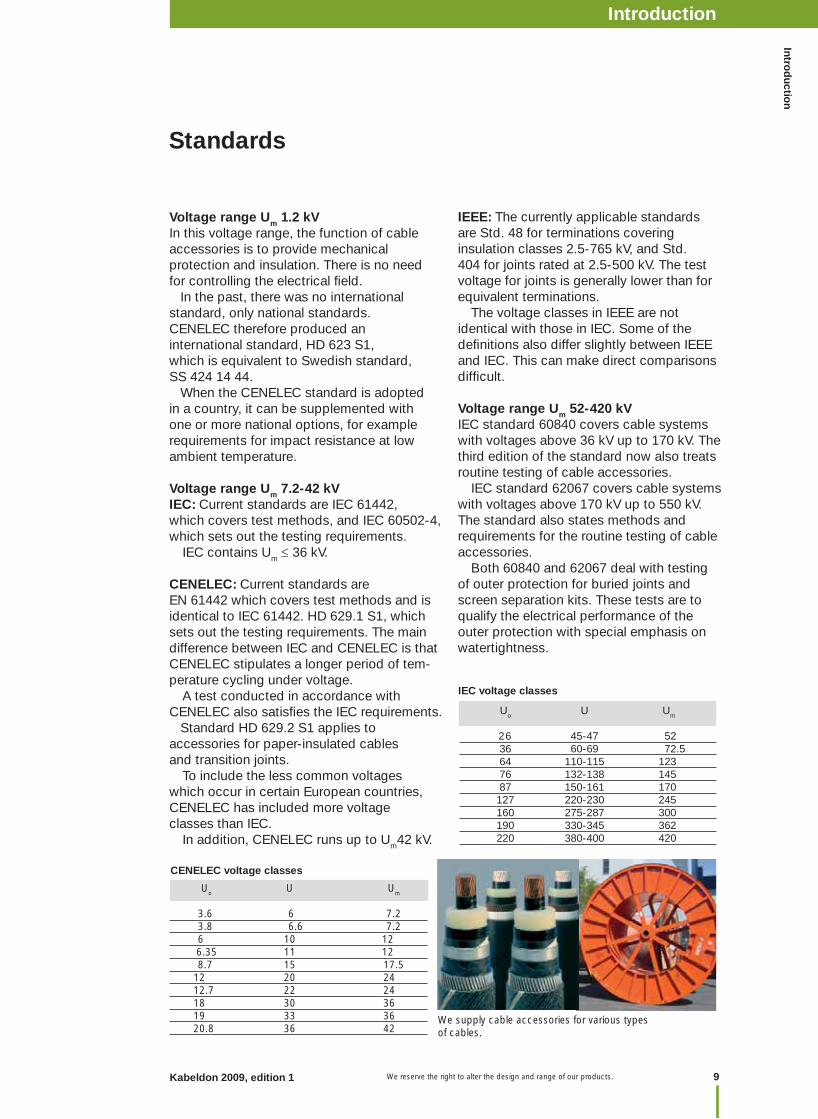
We supply cable accessories for various types of cables.
IEEE: The currently applicable standards are Std. 48 for terminations covering insulation classes 2.5-765 kV, and Std. 404 for joints rated at 2.5-500 kV. The test voltage for joints is generally lower than for equivalent terminations. The voltage classes in IEEE are notidentical with those in IEC. Some of the defi nitions also differ slightly between IEEE and IEC. This can make direct comparisons diffi cult.
Voltage range Um 52-420 kVIEC standard 60840 covers cable systems with voltages above 36 kV up to 170 kV. The third edition of the standard now also treats routine testing of cable accessories. IEC standard 62067 covers cable systems with voltages above 170 kV up to 550 kV. The standard also states methods and requirements for the routine testing of cable accessories. Both 60840 and 62067 deal with testing of outer protection for buried joints and screen separation kits. These tests are to qualify the electrical performance of the outer protection with special emphasis on watertightness.
IEC voltage classes
CENELEC voltage classes
Voltage range Um 1.2 kVIn this voltage range, the function of cable accessories is to provide mechanical protection and insulation. There is no need for controlling the electrical fi eld. In the past, there was no international standard, only national standards. CENELEC therefore produced an international standard, HD 623 S1, which is equivalent to Swedish standard, SS 424 14 44. When the CENELEC standard is adopted in a country, it can be supplemented with one or more national options, for example requirements for impact resistance at low ambient temperature.
Voltage range Um 7.2-42 kVIEC: Current standards are IEC 61442, which covers test methods, and IEC 60502-4, which sets out the testing requirements. IEC contains Um 36 kV.
CENELEC: Current standards are EN 61442 which covers test methods and is identical to IEC 61442. HD 629.1 S1, which sets out the testing requirements. The main difference between IEC and CENELEC is that CENELEC stipulates a longer period of tem-perature cycling under voltage. A test conducted in accordance with CENELEC also satisfi es the IEC requirements. Standard HD 629.2 S1 applies to accessories for paper-insulated cables and transition joints. To include the less common voltages which occur in certain European countries, CENELEC has included more voltage classes than IEC. In addition, CENELEC runs up to Um42 kV.
Uo U Um
26 45-47 52 36 60-69 72.5 64 110-115 123 76 132-138 145 87 150-161 170 127 220-230 245 160 275-287 300 190 330-345 362 220 380-400 420
Uo U Um 3.6 6 7.2 3.8 6.6 7.2 6 10 12 6.35 11 12 8.7 15 17.5 12 20 24 12.7 22 24 18 30 36 19 33 36 20.8 36 42
Standards
IntroductionIntroductionIntroductionIntroduction
10 Kabeldon 2009, edition 1
Introduction
We reserve the right to alter the design and range of our products.
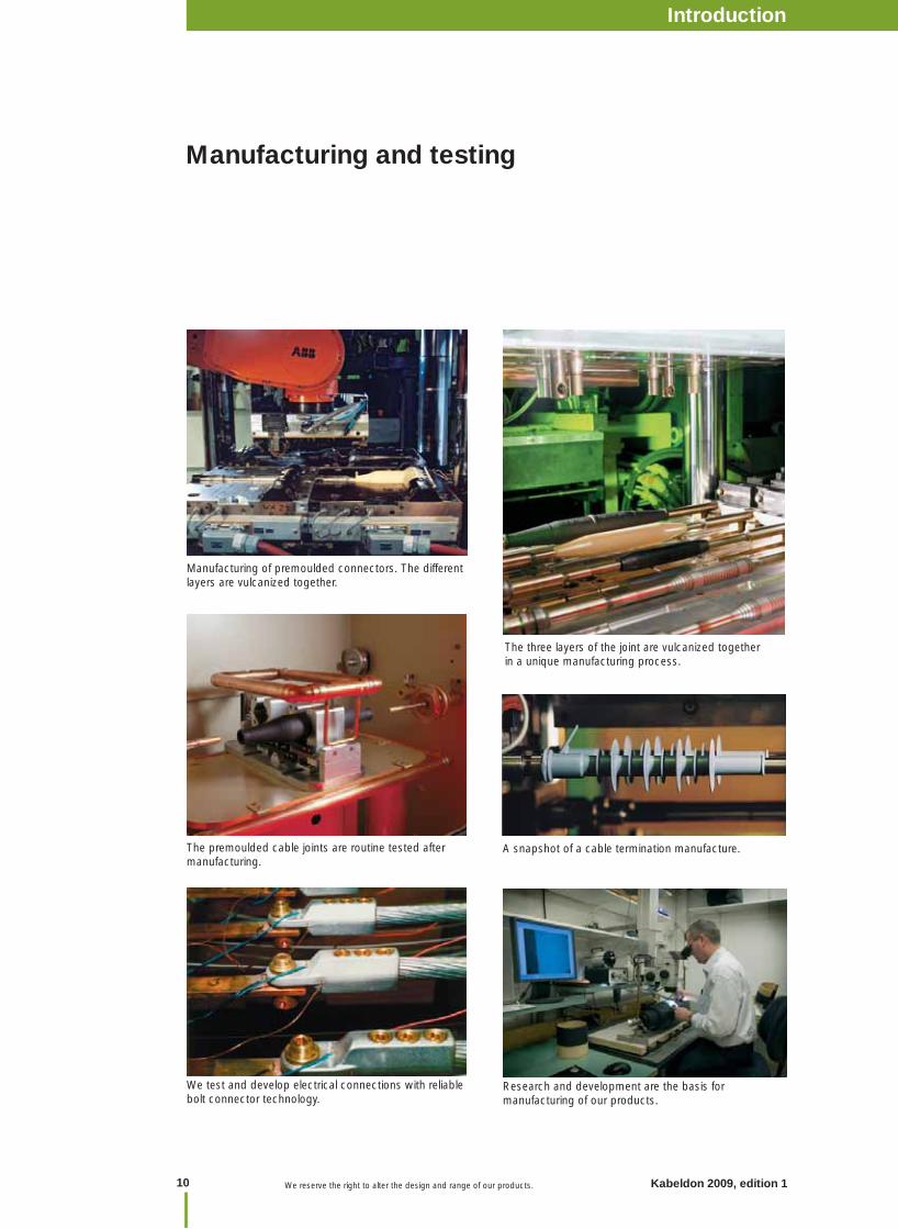
Manufacturing and testing
Manufacturing of premoulded connectors. The different layers are vulcanized together.
We test and develop electrical connections with reliable bolt connector technology.
The three layers of the joint are vulcanized together in a unique manufacturing process.
The premoulded cable joints are routine tested after manufacturing.
A snapshot of a cable termination manufacture.
Research and development are the basis for manufacturing of our products.
11 We reserve the right to alter the design and range of our products. 11Kabeldon 2009, edition 1 We reserve the right to alter the design and range of our products.
Accesso
ries < 1 kV
Table of contentsCable accessories ≤ 1 kV
Page No.
Introduction ........................................................................................................................... 12
Cable joint, cast resin, SMARTA ............................................................................................ 13
Cable joint, branch, SAGA 11Y ............................................................................................. 14
Cable joint, heat-shrink, SMKC ............................................................................................ 15
Cable joint, taped, SMILA, SMULA ....................................................................................... 16
Cable termination, LPH, LXAC .............................................................................................. 17
Protective hood, KAL ............................................................................................................ 19
Cable connection, AK-ADAS ................................................................................................. 20
Kabeldon cable accessories 1 kVKabeldon cable accessories < 1 kV
We reserve the right to alter the design and range of our products.
Introduction Cable accessories ≤ 1 kV
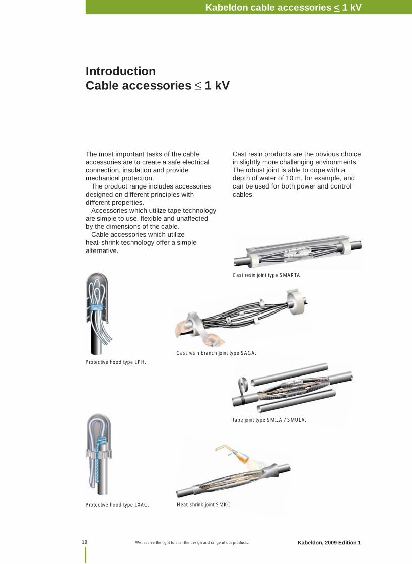
The most important tasks of the cable accessories are to create a safe electrical connection, insulation and provide mechanical protection. The product range includes accessories designed on different principles with different properties. Accessories which utilize tape technology are simple to use, fl exible and unaffected by the dimensions of the cable. Cable accessories which utilize heat-shrink technology offer a simple alternative.
Cast resin joint type SMARTA.
Protective hood type LPH.
Protective hood type LXAC. Heat-shrink joint SMKC
Cast resin branch joint type SAGA.
Tape joint type SMILA / SMULA.
Cast resin products are the obvious choice in slightly more challenging environments.The robust joint is able to cope with a depth of water of 10 m, for example, and can be used for both power and control cables.
Kabeldon cable accessories 1 kVNotes
Kabeldon, 2009 Edition 1
Kabeldon cable accessories 52-420 kV
12
Kabeldon cable accessories < 1 kV
13 We reserve the right to alter the design and range of our products. 13Kabeldon 2009, edition 1 We reserve the right to alter the design and range of our products.
Accesso
ries < 1 kV
Kabeldon cable accessories 1 kV
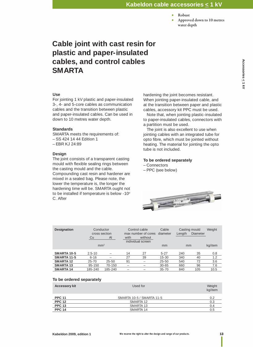
Cable joint with cast resin for plastic and paper-insulated cables, and control cablesSMARTA
• Robust• Approved down to 10 metres water depth
Designation Conductor Control cable Cable Casting mould Weight cross section max number of cores diameter Length Diameter Cu Al with without individual screen mm2 mm mm kg/item
SMARTA 10-5 2.5-10 – 14 27 5-27 240 35 0.8SMARTA 11-5 6-16 – 27 39 15-30 340 40 1.2SMARTA 12 25-70 25-50 91 – 25-50 540 72 3.6 SMARTA 13 95-150 70-150 – – 30-65 660 96 7.6SMARTA 14 185-240 185-240 – – 35-70 840 105 10.5
Accessory kit Used for Weight kg/item
PPC 11 SMARTA 10-5 / SMARTA 11-5 0.2PPC 12 SMARTA 12 0.3PPC 13 SMARTA 13 0.4PPC 14 SMARTA 14 0.5
To be ordered separately
UseFor jointing 1 kV plastic and paper-insulated 3-, 4- and 5-core cables as communication cables and the transition between plastic and paper-insulated cables. Can be used in down to 10 metres water depth.
StandardsSMARTA meets the requirements of:– SS 424 14 44 Edition 1– EBR KJ 24:89
DesignThe joint consists of a transparent casting mould with fl exible sealing rings between the casting mould and the cable. Compounding cast resin and hardener are mixed in a sealed bag. Please note, the lower the temperature is, the longer the hardening time will be. SMARTA ought not to be installed if temperature is below -10o C. After
hardening the joint becomes resistant.When jointing paper-insulated cable, and at the transition between paper and plastic cables, accessory kit PPC must be used. Note that, when jointing plastic-insulated to paper-insulated cables, connectors with a partition must be used. The joint is also excellent to use when jointing cables with an integrated tube for opto fi bre, which must be jointed without heating. The material for jointing the opto tube is not included.
To be ordered separately– Connectors– PPC (see below)
Kabeldon cable accessories < 1 kV
We reserve the right to alter the design and range of our products.
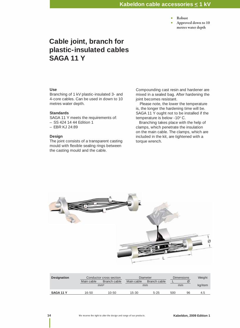
Cable joint, branch for plastic-insulated cables SAGA 11 Y
UseBranching of 1 kV plastic-insulated 3- and 4-core cables. Can be used in down to 10 metres water depth.
StandardsSAGA 11 Y meets the requirements of:– SS 424 14 44 Edition 1– EBR KJ 24:89
DesignThe joint consists of a transparent casting mould with fl exible sealing rings between the casting mould and the cable.
L
Ø
Compounding cast resin and hardener are mixed in a sealed bag. After hardening the joint becomes resistant. Please note, the lower the temperature is, the longer the hardening time will be. SAGA 11 Y ought not to be installed if the temperature is below -10o C. Branching takes place with the help of clamps, which penetrate the insulation on the main cable. The clamps, which are included in the kit, are tightened with a torque wrench.
Designation Conductor cross section Diameter Dimensions Weight Main cable Branch cable Main cable Branch cable L Ø mm² mm mm kg/item SAGA 11 Y 16-50 10-50 15-30 5-25 500 96 4.5
• Robust• Approved down to 10 metres water depth
Kabeldon cable accessories 1 kVNotes
Kabeldon, 2009 Edition 1
Kabeldon cable accessories 52-420 kV
14
Kabeldon cable accessories < 1 kV
15 We reserve the right to alter the design and range of our products. 15Kabeldon 2009, edition 1 We reserve the right to alter the design and range of our products.
Accesso
ries < 1 kV
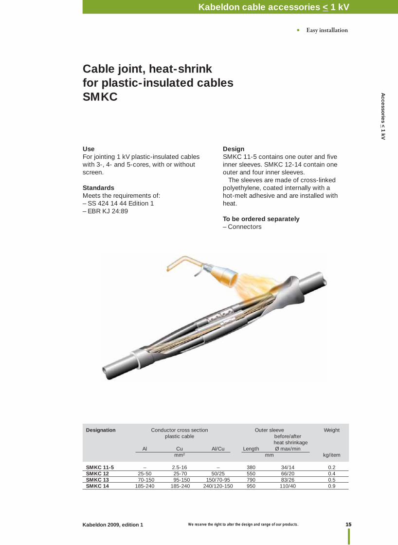
Cable joint, heat-shrink for plastic-insulated cables SMKC
UseFor jointing 1 kV plastic-insulated cableswith 3-, 4- and 5-cores, with or withoutscreen.
StandardsMeets the requirements of:– SS 424 14 44 Edition 1– EBR KJ 24:89
DesignSMKC 11-5 contains one outer and fi ve inner sleeves. SMKC 12-14 contain one outer and four inner sleeves. The sleeves are made of cross-linked polyethylene, coated internally with a hot-melt adhesive and are installed with heat.
To be ordered separately– Connectors
Designation Conductor cross section Outer sleeve Weight plastic cable before/after heat shrinkage Al Cu Al/Cu Length Ø max/min mm² mm kg/item
SMKC 11-5 – 2.5-16 – 380 34/14 0.2SMKC 12 25-50 25-70 50/25 550 66/20 0.4SMKC 13 70-150 95-150 150/70-95 790 83/26 0.5SMKC 14 185-240 185-240 240/120-150 950 110/40 0.9
• Easy installation
Kabeldon cable accessories 1 kVKabeldon cable accessories < 1 kV
We reserve the right to alter the design and range of our products.
Designation Conductor cross section Cable joint Weigh Al Cu Length mm2 mm kg/item SMILA 11 – 2.5-16 420 0.2SMILA 12 25-50 25-70 570 0.3
For larger cable cross sections, use SMILA 12 as below.SMILA 12 (two) 70-150 95-150 770 0.6SMILA 12 (three) 185-240 185-240 920 0.9
SMULA 11 – 2.5-16 420 0.1SMULA 12 25-50 25-70 570 0.3
For larger cable cross sections, use SMULA 12 as below.SMULA 12 (two) 70-150 95-150 770 0.6SMULA 12 (three) 185-240 185-240 920 0.9
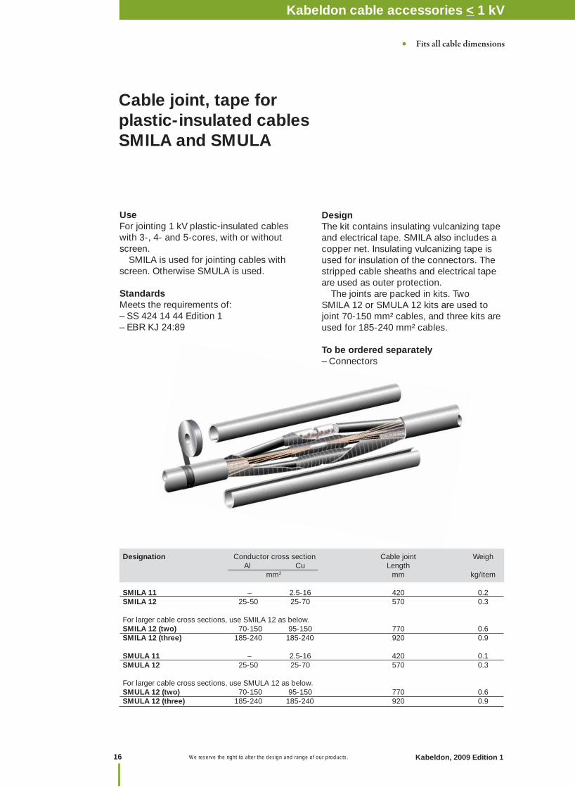
UseFor jointing 1 kV plastic-insulated cables with 3-, 4- and 5-cores, with or without screen. SMILA is used for jointing cables with screen. Otherwise SMULA is used.
StandardsMeets the requirements of:– SS 424 14 44 Edition 1– EBR KJ 24:89
Cable joint, tape for plastic-insulated cables SMILA and SMULA
DesignThe kit contains insulating vulcanizing tape and electrical tape. SMILA also includes a copper net. Insulating vulcanizing tape is used for insulation of the connectors. The stripped cable sheaths and electrical tape are used as outer protection. The joints are packed in kits. Two SMILA 12 or SMULA 12 kits are used to joint 70-150 mm² cables, and three kits are used for 185-240 mm² cables.
To be ordered separately– Connectors
• Fits all cable dimensions
Kabeldon cable accessories 1 kVNotes
Kabeldon, 2009 Edition 1
Kabeldon cable accessories 52-420 kV
16
Kabeldon cable accessories < 1 kV
17 We reserve the right to alter the design and range of our products. 17Kabeldon 2009, edition 1 We reserve the right to alter the design and range of our products.
Accesso
ries < 1 kV
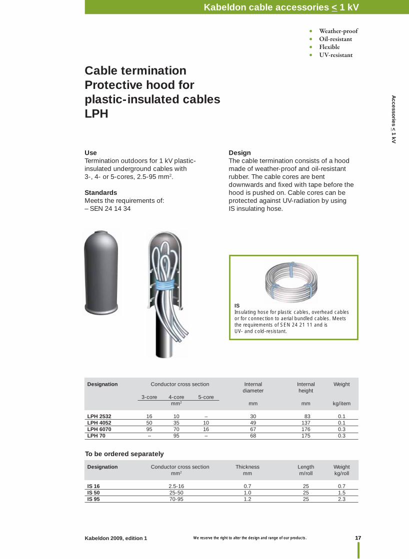
Use Termination outdoors for 1 kV plastic-insulated underground cables with 3-, 4- or 5-cores, 2.5-95 mm2.
StandardsMeets the requirements of:– SEN 24 14 34
Cable terminationProtective hood forplastic-insulated cablesLPH
DesignThe cable termination consists of a hood made of weather-proof and oil-resistant rubber. The cable cores are bent downwards and fi xed with tape before the hood is pushed on. Cable cores can be protected against UV-radiation by using IS insulating hose.
ISInsulating hose for plastic cables, overhead cables or for connection to aerial bundled cables. Meets the requirements of SEN 24 21 11 and is UV- and cold-resistant.
Designation Conductor cross section Internal Internal Weight diameter height 3-core 4-core 5-core mm2 mm mm kg/item
LPH 2532 16 10 – 30 83 0.1LPH 4052 50 35 10 49 137 0.1LPH 6070 95 70 16 67 176 0.3LPH 70 – 95 – 68 175 0.3
Designation Conductor cross section Thickness Length Weight mm2 mm m/roll kg/roll
IS 16 2.5-16 0.7 25 0.7IS 50 25-50 1.0 25 1.5IS 95 70-95 1.2 25 2.3
• Weather-proof • Oil-resistant• Flexible• UV-resistant
To be ordered separately
Kabeldon cable accessories 1 kVKabeldon cable accessories < 1 kV

We reserve the right to alter the design and range of our products.
Cable terminationProtective hood forplastic-insulated cablesLXAC
UseTermination outdoors for 1 kV plastic-insulated underground cables, 2-, 3- or 4-cores 2.5-35 mm2.
StandardsMeets the requirements of:– SEN 24 14 34
DesignThe cable termination consists of a bush-ing and hood made from impact-resistant black polyethylene. The cable cores are bent downwards and pushed into grooves in the bushing before the hood is pushed on. Cable cores can be protected against UV-radiation by using IS insulating hose.
Designation Conductor cross section Max External Height Weight polymeric cable cable diameter 3-, and 4-core diameter Ø mm² mm mm mm kg/item
LXAC 116 16 27 60 100 0.1LXAC 135 35 31 75 125 0.1
Designation Conductor cross section Thickness Length Weight mm² mm m/roll kg/roll
IS 16 2.5-16 0.7 25 0.7IS 50 25-50 1.0 25 1.5
• Weather-proof • Oil-resistant• Impact resisting• UV-resistant
To be ordered separately
ISInsulating hose for plastic cables, overhead cables or for connection to aerial bundled cables. Meets the requirements of SEN 24 21 11 and is UV- and cold-resistant.
Kabeldon cable accessories 1 kVNotes
Kabeldon, 2009 Edition 1
Kabeldon cable accessories 52-420 kV
18
Kabeldon cable accessories < 1 kV
19 We reserve the right to alter the design and range of our products. 19Kabeldon 2009, edition 1 We reserve the right to alter the design and range of our products.
Accesso
ries < 1 kV
Protective HoodConnection protection for plastic-insulated cables KAL
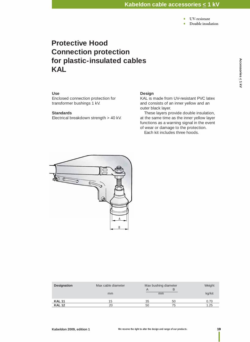
UseEnclosed connection protection for transformer bushings 1 kV.
StandardsElectrical breakdown strength > 40 kV.
DesignKAL is made from UV-resistant PVC latex and consists of an inner yellow and an outer black layer. These layers provide double insulation, at the same time as the inner yellow layer functions as a warning signal in the event of wear or damage to the protection. Each kit includes three hoods.
• UV-resistant• Double insulation
Kabeldon cable accessories 1 kV
A
B
Designation Max cable diameter Max bushing diameter Weight A B mm mm kg/kit
KAL 11 15 35 50 0.70KAL 12 20 50 75 1.25
Kabeldon cable accessories < 1 kV
We reserve the right to alter the design and range of our products.
Cable connection , prefabricated AK-ADAS
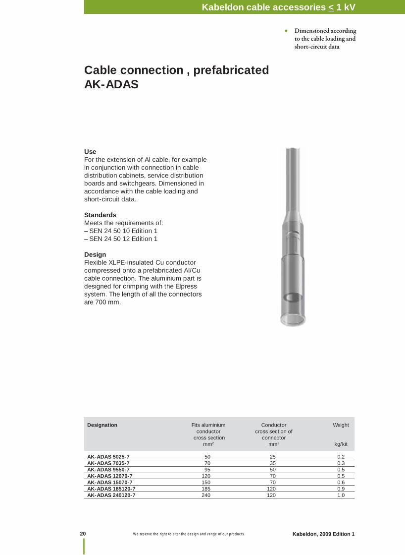
Use For the extension of Al cable, for example in conjunction with connection in cable distribution cabinets, service distribution boards and switchgears. Dimensioned in accordance with the cable loading and short-circuit data.
StandardsMeets the requirements of:– SEN 24 50 10 Edition 1– SEN 24 50 12 Edition 1
DesignFlexible XLPE-insulated Cu conductor compressed onto a prefabricated Al/Cu cable connection. The aluminium part is designed for crimping with the Elpress system. The length of all the connectors are 700 mm.
Designation Fits aluminium Conductor Weight conductor cross section of cross section connector mm2 mm2 kg/kit AK-ADAS 5025-7 50 25 0.2AK-ADAS 7035-7 70 35 0.3AK-ADAS 9550-7 95 50 0.5AK-ADAS 12070-7 120 70 0.5AK-ADAS 15070-7 150 70 0.6AK-ADAS 185120-7 185 120 0.9AK-ADAS 240120-7 240 120 1.0
• Dimensioned according to the cable loading and short-circuit data
Kabeldon cable accessories 1 kVKabeldon cable accessories 1 kVNotes
Kabeldon, 2009 Edition 1
Kabeldon cable accessories 52-420 kV
20
Kabeldon cable accessories < 1 kV
21Kabeldon 2009, edition 1 We reserve the right to alter the design and range of our products.
Accesso
ries XLP
E 12-36 kV
Table of contentsCable accessories 12-36 kV
Page No.
Introduction ........................................................................................................................... 22
Cable accessories for XLPE-insulated cables
Quick guide to choosing cable accessories for XLPE-insulated cables ............................... 23
Dimensional drawings for installation of cable terminations ................................................. 24
Cable terminations with resistive/refractive fi eld control 10-36 kV, SOT .............................. 25
Cable connectors, screened separable 12-24 kV, SOC ........................................................ 29
Cable termination, shrouded 12 kV, TB-A 12 ........................................................................ 35
Cable termination, shrouded 12-24 kV, KAP 12-24 kV ......................................................... 36
Cable joint with geometrical fi eld control,12-24 kV, SOJ ...................................................... 40
Cable joint with resistive/refractive fi eld control, tape 12-36 kV, SMXB ............................... 46
Cable cabinet for branching 12-24 kV, HDC ......................................................................... 49
Screen separation kit, PSSK, PSSK-E .................................................................................. 53
Branch seal kit, TSH .............................................................................................................. 54
Earthing kits for cable terminations, JXT, JSA ...................................................................... 55
Screen connection for cable joints, JSA ............................................................................... 56
Armouring kit, ARM ............................................................................................................... 57
Connectors ............................................................................................................................ 58
Bird protection ....................................................................................................................... 60
Cable accessories for paper-insulated cables
Cable termination 12 kV, OTIA .............................................................................................. 61
Cable joint and repair joints 12 kV, SMTD ............................................................................. 63
Cable joint, transition 12 kV, SMTXB ..................................................................................... 65
Cable joint, transition 24-36 kV, SMTXD .............................................................................. 66
Cable joints 24-52 kV, SMTA and SMTPA ............................................................................ 67
Dimensional drawings, SMT .................................................................................................. 68
Spring-loaded gaskets .......................................................................................................... 69
Accessories for joints and transition joints ............................................................................ 70
General accessories .............................................................................................................. 72
Tools ...................................................................................................................................... 75
Kabeldon cable accessories for XLPE cables 12-36 kV
We reserve the right to alter the design and range of our products.22 Kabeldon 2009, edition 1
Introduction Cable accessories 12-36 kV
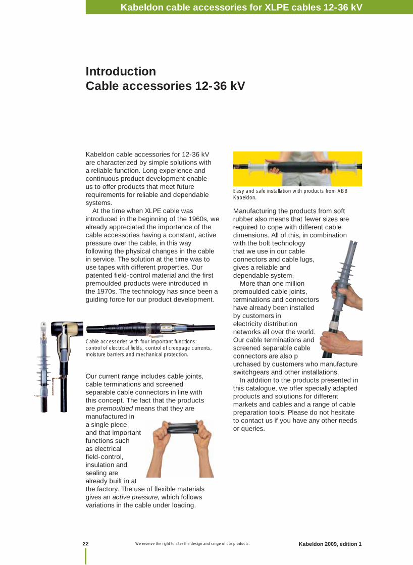
Cable accessories with four important functions: control of electrical fi elds, control of creepage currents, moisture barriers and mechanical protection.
Easy and safe installation with products from ABB Kabeldon.
Kabeldon cable accessories for 12-36 kV are characterized by simple solutions with a reliable function. Long experience and continuous product development enable us to offer products that meet future requirements for reliable and dependable systems. At the time when XLPE cable was introduced in the beginning of the 1960s, we already appreciated the importance of the cable accessories having a constant, active pressure over the cable, in this way following the physical changes in the cable in service. The solution at the time was to use tapes with different properties. Our patented fi eld-control material and the fi rst premoulded products were introduced in the 1970s. The technology has since been a guiding force for our product development.
Our current range includes cable joints, cable terminations and screened separable cable connectors in line with this concept. The fact that the products are premoulded means that they are manufactured in a single piece and that important functions such as electrical fi eld-control, insulation and sealing are already built in at the factory. The use of fl exible materials gives an active pressure, which follows variations in the cable under loading.
Manufacturing the products from soft rubber also means that fewer sizes are required to cope with different cable dimensions. All of this, in combination with the bolt technology that we use in our cable connectors and cable lugs, gives a reliable and dependable system. More than one million premoulded cable joints, terminations and connectors have already been installed by customers in electricity distribution networks all over the world. Our cable terminations and screened separable cable connectors are also purchased by customers who manufacture switchgears and other installations. In addition to the products presented in this catalogue, we offer specially adapted products and solutions for different markets and cables and a range of cable preparation tools. Please do not hesitate to contact us if you have any other needs or queries.
Kabeldon cable accessories for XLPE cables 12-36 kV

23Kabeldon 2009, edition 1 We reserve the right to alter the design and range of our products.
Accesso
ries XLP
E 12-36 kV
Quick guide to choosing cable accessories for XLPE-insulated cables 12-36 kV
Taped joint1. Joint type SMXB -3 Page 46-482. Screen connection kit type JSA 10-13 Page 563. Armouring kit type ARM Page 57
Indoor termination1. Termination type SOT Page 25-282. Earthing kit type JSA Page 55
Outdoor termination1. Termination type SOT-31 Page 25-282. Earthing kit type JSA Page 55
Screened separable connector 1. Connector type SOC Page 29-342. Earthing kit type JSA Page 55
Insulated connector 1. Connector type KAP Page 36-392. Earthing kit type JSA Page 55
Prefabricated joint 1. Three joints type SOJ-1 Page 40-452. Screen connection kit type JSA 14-16 Page 56
Taped joint 1. Joint type SMXB -3 Page 46-482. Screen connection kit type JSA 14-16 Page 56
Aluminium foilArmouring
Copper tape screen
3-core cables with copper tape screen and armouring
Three 1-core cables with Al foil screen
The kits shown in this section of the catalogue can be used on cables with copper wire screen, as described. For other types of screen, the accessories must be adapted as follows:
Suitable kits of cable joints, terminations and screened separable connectors are available for this cable type. Contact us for information.
Kabeldon cable accessories for XLPE cables 12-36 kV
We reserve the right to alter the design and range of our products.24 Kabeldon 2009, edition 1
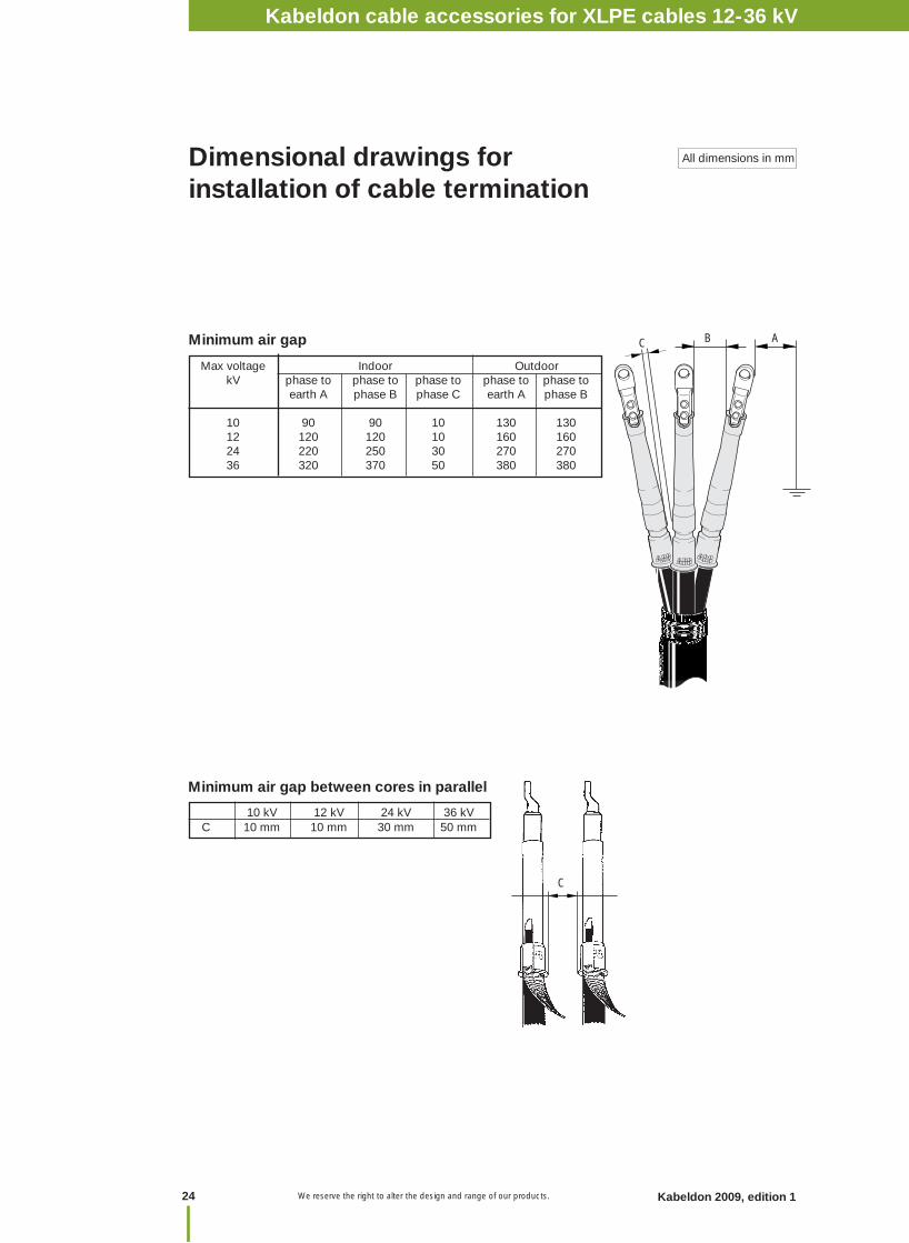
Minimum air gap
Dimensional drawings for installation of cable termination
Minimum air gap between cores in parallel
All dimensions in mm
Kabeldon cable accessories 12-36 kV
10 kV 12 kV 24 kV 36 kV C 10 mm 10 mm 30 mm 50 mm
C
Max voltage Indoor Outdoor kV phase to phase to phase to phase to phase to earth A phase B phase C earth A phase B
10 90 90 10 130 130 12 120 120 10 160 160 24 220 250 30 270 270 36 320 370 50 380 380
B AC
Kabeldon cable accessories for XLPE cables 12-36 kV

25Kabeldon 2009, edition 1 We reserve the right to alter the design and range of our products.
Accesso
ries XLP
E 12-36 kV
UsePremoulded cable termination for XLPE-insulated cables with Al or Cu conductor for 6.6/10 kV, indoors. It can also be installed in an indoor humid environment.
StandardsMeets the requirements of:CENELEC– HD 629.1 S1
DesignPremoulded cable termination; rubber sleeve with integrated fi eld control. The length of the termination is approx.145 mm which also makes it suitable for installations in narrow spaces. The terminations are supplied in kits for 3-phase cables. Kits with outdoor terminations for 3-core cables include crutch seal and protective heat shrink hoses.
Cable termination indoor, premoulded SOT 10 kV
Designation XLPE-Ø Conductor Weight cross section mm mm2 kg/kit
3-core / three 1-coreSOT 101-3 10.5-15 10-35 0.2SOT 102-3 12.9-25.8 50-185 0.2SOT 103-3 21.4-34.9 185- 500 0.2
• Cold-applied• Can be used in small spaces• No special tools• Premoulded for easy and safe installation• Minimal cable stripping• Active pressure• Few components• Long shelf life
Min
200
135
Kabeldon cable accessories for XLPE cables 12-36 kV
We reserve the right to alter the design and range of our products.26 Kabeldon 2009, edition 1
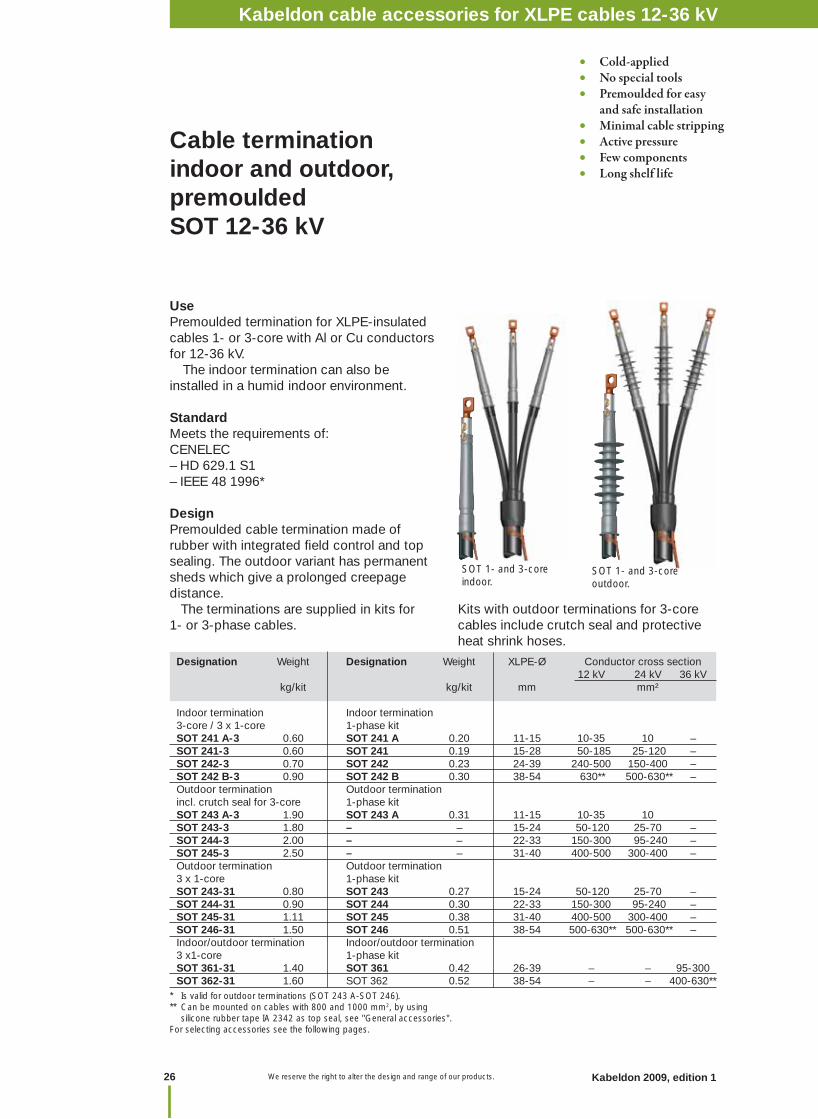
Cable termination indoor and outdoor, premoulded SOT 12-36 kV
Designation Weight Designation Weight XLPE-Ø Conductor cross section 12 kV 24 kV 36 kV kg/kit kg/kit mm mm²
Indoor termination Indoor termination 3-core / 3 x 1-core 1-phase kitSOT 241 A-3 0.60 SOT 241 A 0.20 11-15 10-35 10 – SOT 241-3 0.60 SOT 241 0.19 15-28 50-185 25-120 – SOT 242-3 0.70 SOT 242 0.23 24-39 240-500 150-400 – SOT 242 B-3 0.90 SOT 242 B 0.30 38-54 630** 500-630** – Outdoor termination Outdoor termination incl. crutch seal for 3-core 1-phase kitSOT 243 A-3 1.90 SOT 243 A 0.31 11-15 10-35 10 SOT 243-3 1.80 – – 15-24 50-120 25-70 – SOT 244-3 2.00 – – 22-33 150-300 95-240 – SOT 245-3 2.50 – – 31-40 400-500 300-400 – Outdoor termination Outdoor termination3 x 1-core 1-phase kitSOT 243-31 0.80 SOT 243 0.27 15-24 50-120 25-70 – SOT 244-31 0.90 SOT 244 0.30 22-33 150-300 95-240 – SOT 245-31 1.11 SOT 245 0.38 31-40 400-500 300-400 – SOT 246-31 1.50 SOT 246 0.51 38-54 500-630** 500-630** – Indoor/outdoor termination Indoor/outdoor termination 3 x1-core 1-phase kitSOT 361-31 1.40 SOT 361 0.42 26-39 – – 95-300 SOT 362-31 1.60 SOT 362 0.52 38-54 – – 400-630**
* Is valid for outdoor terminations (SOT 243 A-SOT 246).** Can be mounted on cables with 800 and 1000 mm2, by using silicone rubber tape IA 2342 as top seal, see "General accessories".For selecting accessories see the following pages.
UsePremoulded termination for XLPE-insulated cables 1- or 3-core with Al or Cu conductors for 12-36 kV. The indoor termination can also be installed in a humid indoor environment.
StandardMeets the requirements of:CENELEC– HD 629.1 S1– IEEE 48 1996*
DesignPremoulded cable termination made of rubber with integrated fi eld control and top sealing. The outdoor variant has permanent sheds which give a prolonged creepage distance. The terminations are supplied in kits for 1- or 3-phase cables.
Kits with outdoor terminations for 3-core cables include crutch seal and protective heat shrink hoses.
• Cold-applied• No special tools• Premoulded for easy and safe installation• Minimal cable stripping• Active pressure• Few components• Long shelf life
SOT 1- and 3-core indoor.
SOT 1- and 3-core outdoor.
Kabeldon cable accessories 12-36 kVKabeldon cable accessories for XLPE cables 12-36 kV

27Kabeldon 2009, edition 1 We reserve the right to alter the design and range of our products.
Accesso
ries XLP
E 12-36 kV
Kits complete with screw cable lugCable termination including bi-metallic screw cable lug for Al and Cu conductors.The cable lug is equipped with shear-off bolts.
Designation Weight Designation Weight Cable cross section 12 kV 24 kV kg/kit kg/kit mm²
1-core indoor 3 -core / 3 x 1-core indoor SOT 241A S1 0.35 SOT 241A-3 S1 1.05 16 - 35 16 SOT 241 S1 0.34 SOT 241-3 S1 1.02 50 - 70 25 - 70 SOT 241 S2 0.44 SOT 241-3 S2 1.32 95 - 150 95 - 120 SOT 241 S3 0.59 SOT 241-3 S3 1.50 185 – SOT 242 S2 0.48 SOT 242-3 S2 1.44 – 150 SOT 242 S3 0.63 SOT 242-3 S3 1.89 240 185 - 240 SOT 242 S4 0.98 SOT 242-3 S4 2.94 300 - 400 300 - 400 SOT 242B S5 1.78 SOT 242B-3 S5 5.25 500 - 630 500 - 630
1-core outdoor 3-core outdoor SOT 243A S1 0.46 SOT 243A-3 S1 1.56 16 - 35 16 SOT 243 S1 0.42 SOT 243-3 S1 1.42 50 - 70 25 - 70 SOT 243 S2 0.52 SOT 243-3 S2 1.52 95 - 120 – SOT 244 S2 0.55 SOT 244-3 S2 1.65 150 95 - 150 SOT 244 S3 0.70 SOT 244-3 S3 1.80 185 - 240 185 - 240SOT 244 S4 1.05 SOT 244-3 S4 2.15 300 –SOT 245 S4 1.13 SOT 245-3 S4 2.51 400 300 - 400 SOT 245 S5 1.83 SOT 245-3 S5 3.15 500 – SOT 246 S5 1.96 – – 630 500 - 630
3 x 1-core outdoorSOT 243 A-31 S1 1.38 16-35 16 SOT 243-31 S1 1.26 50-70 25-70 SOT 243-31 S2 1.56 95 - 120 – SOT 244-31 S2 1.65 150 95 - 150 SOT 244-31 S3 2.10 185 - 240 185 - 240SOT 244-31 S4 3.15 300 – SOT 245-31 S4 3.40 400 300 - 400 SOT 245-31 S5 5.50 500 – SOT 246-31 S5 5.90 630 500 - 630 1-core indoor/outdoor 36 kV SOT 361 S2 0.67 95 - 150 – SOT 361 S3 0.82 185 - 240 – SOT 361 S4 1.17 300 – SOT 362 S4 1.27 400 – SOT 362 S5 1.97 500 - 630 – 3 x 1-core indoor/outdoor 36 kV SOT 361-31 S2 2.10 95 - 150 –SOT 361-31 S3 2.46 185 - 240 – SOT 361-31 S4 3.50 300 –SOT 362-31 S4 3.80 400 –SOT 362-31 S5 5.95 500 - 630 –
Kabeldon cable accessories for XLPE cables 12-36 kV
We reserve the right to alter the design and range of our products.28 Kabeldon 2009, edition 1
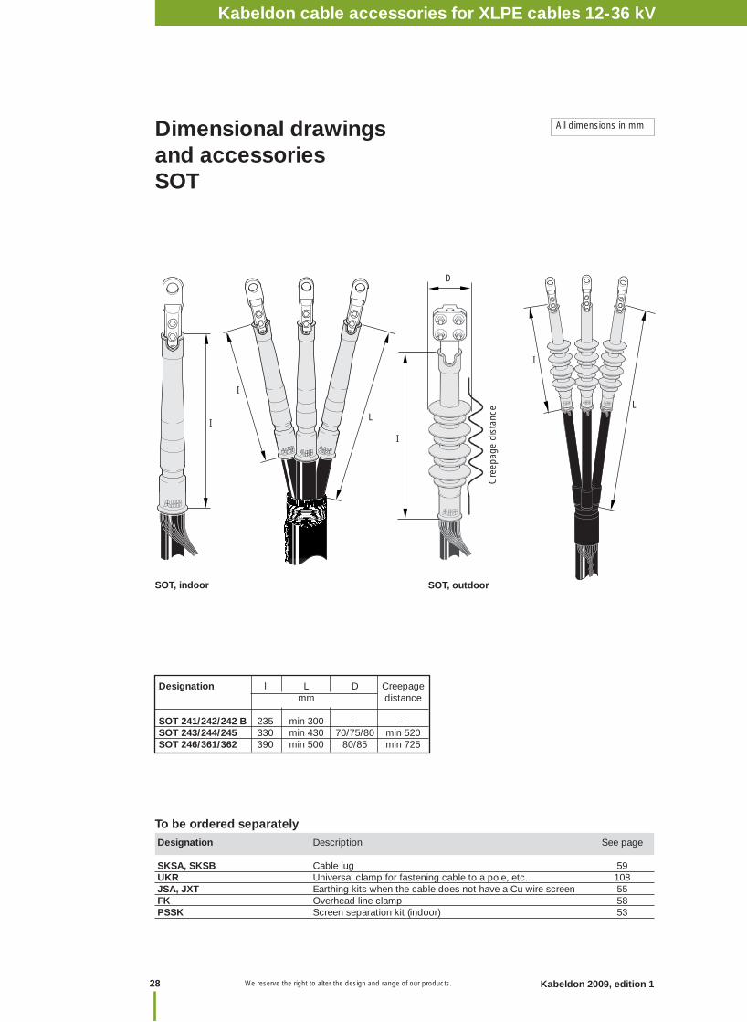
Dimensional drawings and accessoriesSOT
Designation Description See page SKSA, SKSB Cable lug 59UKR Universal clamp for fastening cable to a pole, etc. 108JSA, JXT Earthing kits when the cable does not have a Cu wire screen 55FK Overhead line clamp 58PSSK Screen separation kit (indoor) 53
SOT, outdoorSOT, indoor
I
I
IL
D
To be ordered separately
Cre
epag
e di
stan
ce
Kabeldon cable accessories 12-36 kV
I
L
Designation l L D Creepage mm distance
SOT 241/242/242 B 235 min 300 – –SOT 243/244/245 330 min 430 70/75/80 min 520SOT 246/361/362 390 min 500 80/85 min 725
All dimensions in mm
Kabeldon cable accessories for XLPE cables 12-36 kV
29Kabeldon 2009, edition 1 We reserve the right to alter the design and range of our products.
Accesso
ries XLP
E 12-36 kV
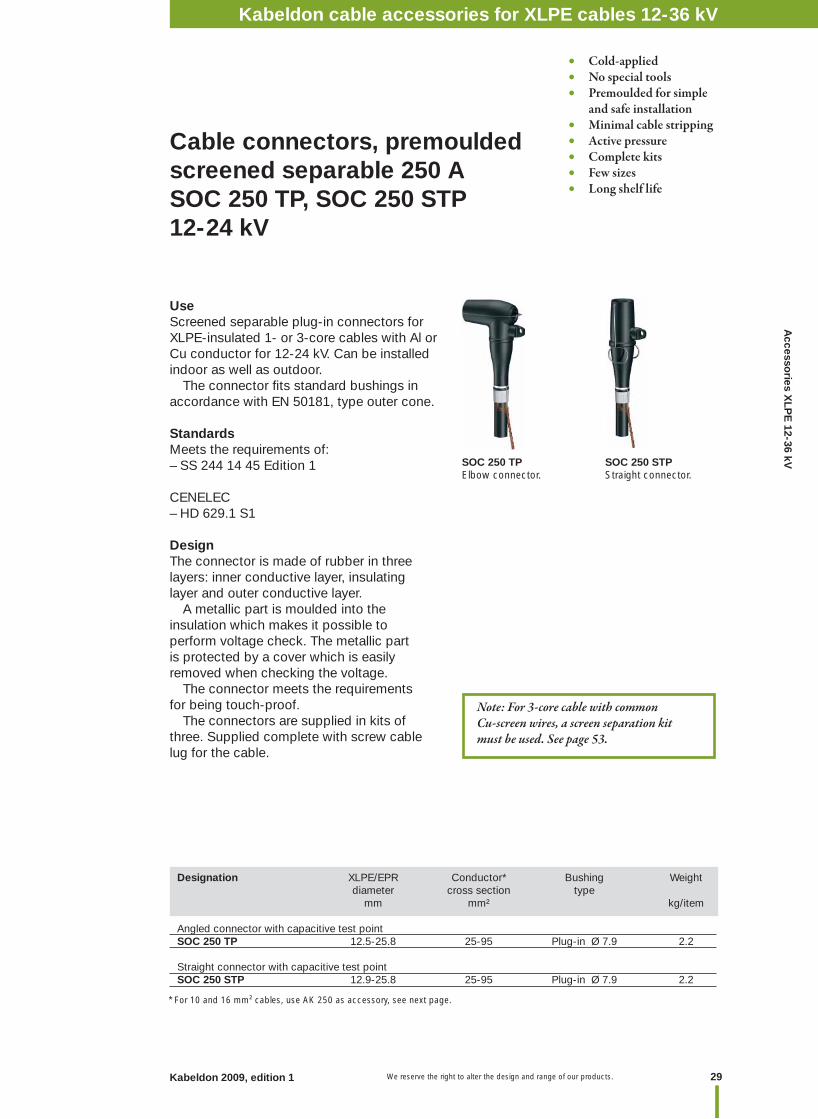
UseScreened separable plug-in connectors for XLPE-insulated 1- or 3-core cables with Al or Cu conductor for 12-24 kV. Can be installed indoor as well as outdoor. The connector fi ts standard bushings in accordance with EN 50181, type outer cone.
StandardsMeets the requirements of:– SS 244 14 45 Edition 1
CENELEC– HD 629.1 S1
DesignThe connector is made of rubber in three layers: inner conductive layer, insulating layer and outer conductive layer. A metallic part is moulded into the insulation which makes it possible to perform voltage check. The metallic part is protected by a cover which is easily removed when checking the voltage. The connector meets the requirements for being touch-proof. The connectors are supplied in kits of three. Supplied complete with screw cable lug for the cable.
Cable connectors, premoulded screened separable 250 A SOC 250 TP, SOC 250 STP 12-24 kV
Designation XLPE/EPR Conductor* Bushing Weight diameter cross section type mm mm² kg/item
Angled connector with capacitive test pointSOC 250 TP 12.5-25.8 25-95 Plug-in Ø 7.9 2.2
Straight connector with capacitive test point SOC 250 STP 12.9-25.8 25-95 Plug-in Ø 7.9 2.2
• Cold-applied • No special tools • Premoulded for simple and safe installation• Minimal cable stripping • Active pressure• Complete kits• Few sizes• Long shelf life
SOC 250 TPElbow connector.
SOC 250 STPStraight connector.
Kabeldon cable accessories 12-36 kV
* For 10 and 16 mm² cables, use AK 250 as accessory, see next page.
Note: For 3-core cable with common Cu-screen wires, a screen separation kit must be used. See page 53.
Kabeldon cable accessories for XLPE cables 12-36 kV
We reserve the right to alter the design and range of our products.30 Kabeldon 2009, edition 1
R3R1
C 2x45°
Bail holderØ 4
3.5
Ø 4
8.5
Ø 9
0
Ø 3
1
1
Ø 3
2.5
9
Fits bushing 200 series 250 A as above.
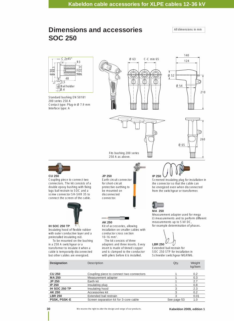
Dimensions and accessories SOC 250
All dimensions in mm
Kabeldon cable accessories 12-36 kV
Standard bushing EN 50181200 series 250 AContact type: Plug-in Ø 7.9 mmInterface type: A
Designation Description Qty. Weight kg/item
CU 250 Coupling piece to connect two connectors 1 0.2MA 250 Measurement adapter 1 0.3JP 250 Earth kit 1 2.7IP 250 Insulating plug 1 0.8IH SOC 250 TP Insulating hood 3 2.3AK 250 Accessories kit 3 0.2LBR 250 Extended bail restrain 3 0.01PSSK, PSSK-E Screen separation kit for 3-core cable See page 53 1.0
AK 250Kit of accessories, allowing installation on smaller cables with conductor cross section 10-16 mm2. The kit consists of three adapters and three inserts. Every insert is made of tinned copper and is clamped to the conductor with pliers before it is installed.
CU 250Coupling piece to connect two connectors. The kit consists of a double epoxy bushing with fi xing lugs bail restrain to SOC and a screw connector SH-SKR 35 to connect the screen of the cable.
LBR 250Extended bail restrain for SOC 250 STP for installation in Schneider switchgear MGRM6.
JP 250Earth circuit connector for short-circuit protective earthing to be mounted on disconnected connector.
MA 250Measurement adapter used for mega measurements and to perform different measurements up to 5 kV DC, for example determination of phases.
IP 250Screened insulating plug for installation in the connector so that the cable can be energized even when disconnected from the switchgear or transformer.
IH SOC 250 TPInsulating hood of fl exible rubber with outer conductive layer and a preinstalled insulating rod. To be mounted on the bushing in a 250 A switchgear or a transformer to insulate it when a cable is temporarily disconnected but other cables are energized.
48
Ø 63 C-C min 65
Ø 52
Ø 54
124
210
140
Ø 65
260
Kabeldon cable accessories for XLPE cables 12-36 kV
31Kabeldon 2009, edition 1 We reserve the right to alter the design and range of our products.
Accesso
ries XLP
E 12-36 kV
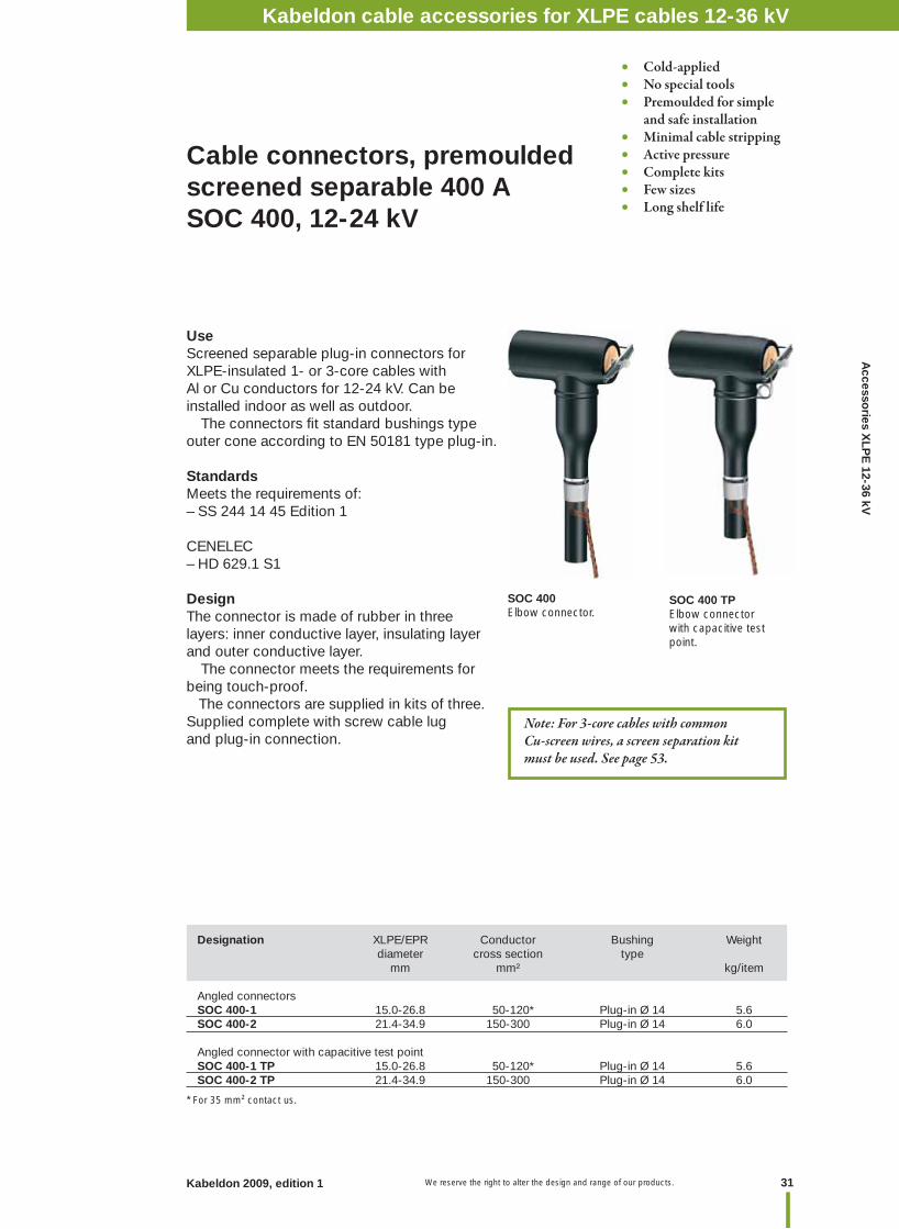
UseScreened separable plug-in connectors forXLPE-insulated 1- or 3-core cables withAl or Cu conductors for 12-24 kV. Can be installed indoor as well as outdoor. The connectors fi t standard bushings type outer cone according to EN 50181 type plug-in.
StandardsMeets the requirements of:– SS 244 14 45 Edition 1
CENELEC– HD 629.1 S1
DesignThe connector is made of rubber in three layers: inner conductive layer, insulating layer and outer conductive layer. The connector meets the requirements for being touch-proof. The connectors are supplied in kits of three.Supplied complete with screw cable lug and plug-in connection.
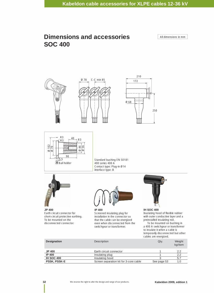
Cable connectors, premoulded screened separable 400 A SOC 400, 12-24 kV
Designation XLPE/EPR Conductor Bushing Weight diameter cross section type mm mm² kg/item
Angled connectors SOC 400-1 15.0-26.8 50-120* Plug-in Ø 14 5.6SOC 400-2 21.4-34.9 150-300 Plug-in Ø 14 6.0
Angled connector with capacitive test pointSOC 400-1 TP 15.0-26.8 50-120* Plug-in Ø 14 5.6SOC 400-2 TP 21.4-34.9 150-300 Plug-in Ø 14 6.0
* For 35 mm² contact us.
SOC 400Elbow connector.
• Cold-applied • No special tools • Premoulded for simple and safe installation• Minimal cable stripping • Active pressure• Complete kits• Few sizes• Long shelf life
SOC 400 TPElbow connector with capacitive test point.
Kabeldon cable accessories 12-36 kV
Note: For 3-core cables with common Cu-screen wires, a screen separation kit must be used. See page 53.
Kabeldon cable accessories for XLPE cables 12-36 kV
We reserve the right to alter the design and range of our products.32 Kabeldon 2009, edition 1
Standard bushing EN 50181400 series 400 AContact type: Plug-in Ø14Interface type: B
Ø 68
172
210 Ø 78 C-C min 85
250
R3
Ø 4
6
Ø 7
0Ø
102
115.5Bail holder
40R3R3
Ø 5
6
90
All dimensions in mmDimensions and accessoriesSOC 400
IP 400Screened insulating plug for installation in the connector so that the cable can be energized even when disconnected from the switchgear or transformer.
JP 400Earth circuit connector for short-circuit protective earthing. To be mounted on the disconnected connector.
Designation Description Qty. Weight kg/item JP 400 Earth circuit connector 1 2.2IP 400 Insulating plug 1 2.2IH SOC 400 Insulating hood 3 5.7PSSK, PSSK-E Screen separation kit for 3-core cable See page 53 1.0
IH SOC 400Inuslating hood of fl exible rubber with outer conductive layer and a preinstalled insulating rod. To be mounted on bushing in a 400 A switchgear or transformer to insulate it when a cable is temporarily disconnected but other cables are energized.
Kabeldon cable accessories for XLPE cables 12-36 kV
33Kabeldon 2009, edition 1 We reserve the right to alter the design and range of our products.
Accesso
ries XLP
E 12-36 kV
• Cold-applied • No special tools • Premoulded for simple and safe installation• Minimal cable stripping • Active pressure• Complete kits• Few sizes• Long shelf life
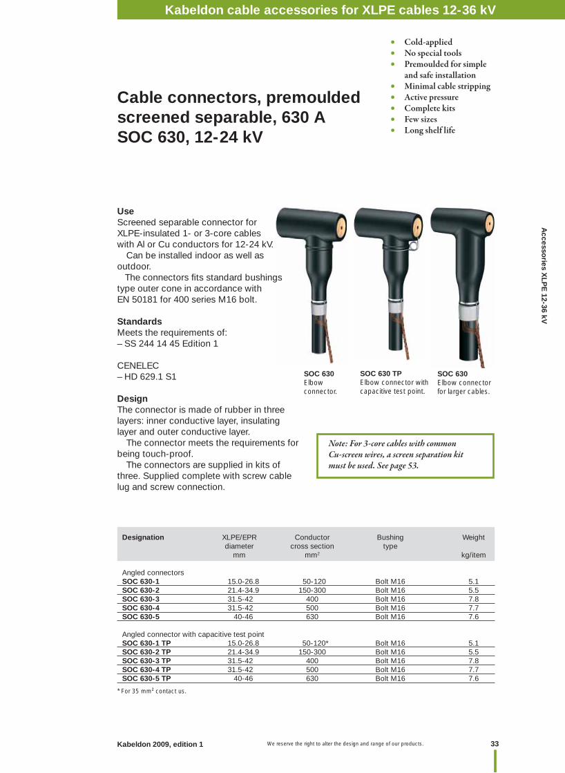
Cable connectors, premoulded screened separable, 630 A SOC 630, 12-24 kV
Designation XLPE/EPR Conductor Bushing Weight diameter cross section type mm mm2 kg/item
Angled connectors SOC 630-1 15.0-26.8 50-120 Bolt M16 5.1SOC 630-2 21.4-34.9 150-300 Bolt M16 5.5SOC 630-3 31.5-42 400 Bolt M16 7.8SOC 630-4 31.5-42 500 Bolt M16 7.7SOC 630-5 40-46 630 Bolt M16 7.6
Angled connector with capacitive test pointSOC 630-1 TP 15.0-26.8 50-120* Bolt M16 5.1 SOC 630-2 TP 21.4-34.9 150-300 Bolt M16 5.5SOC 630-3 TP 31.5-42 400 Bolt M16 7.8 SOC 630-4 TP 31.5-42 500 Bolt M16 7.7 SOC 630-5 TP 40-46 630 Bolt M16 7.6
* For 35 mm² contact us.
SOC 630Elbow connector.
SOC 630 TPElbow connector with capacitive test point.
Kabeldon cable accessories 12-36 kV
SOC 630Elbow connector for larger cables.
Note: For 3-core cables with common Cu-screen wires, a screen separation kit must be used. See page 53.
UseScreened separable connector forXLPE-insulated 1- or 3-core cables with Al or Cu conductors for 12-24 kV. Can be installed indoor as well as outdoor. The connectors fi ts standard bushings type outer cone in accordance with EN 50181 for 400 series M16 bolt.
StandardsMeets the requirements of:– SS 244 14 45 Edition 1
CENELEC– HD 629.1 S1
DesignThe connector is made of rubber in three layers: inner conductive layer, insulating layer and outer conductive layer. The connector meets the requirements for being touch-proof. The connectors are supplied in kits of three. Supplied complete with screw cable lug and screw connection.
Kabeldon cable accessories for XLPE cables 12-36 kV
We reserve the right to alter the design and range of our products.34 Kabeldon 2009, edition 1
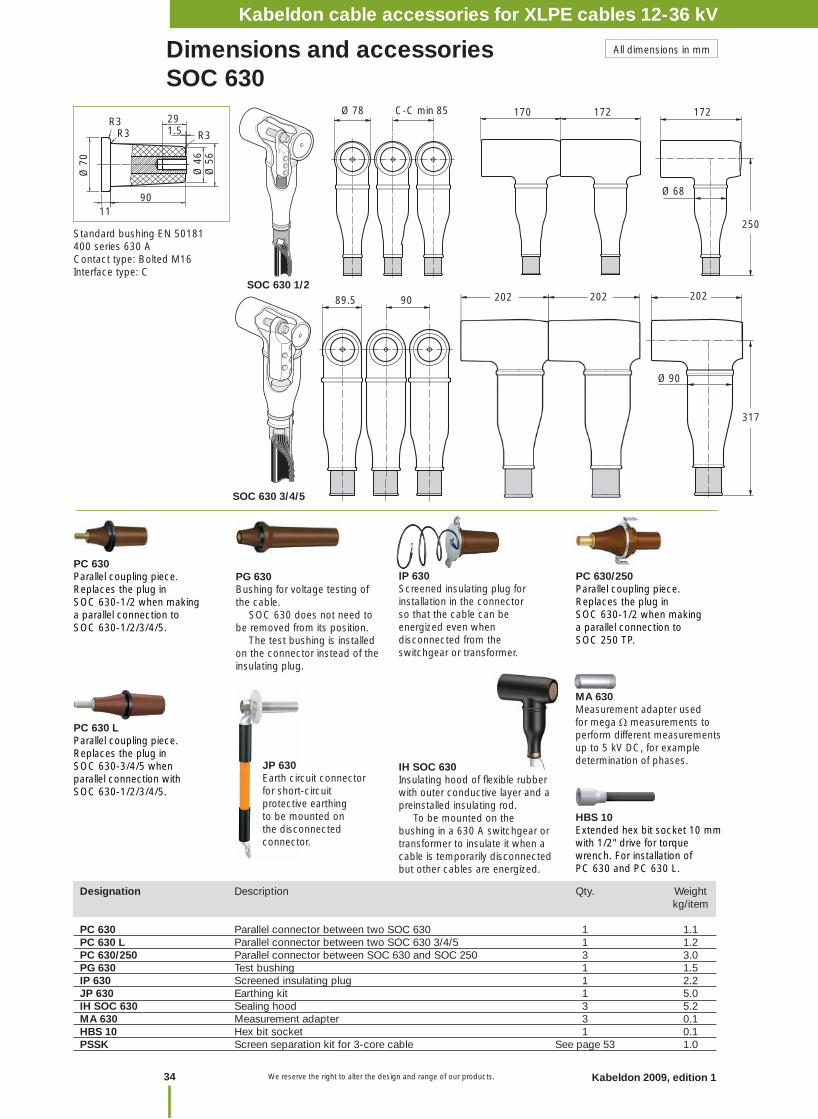
Dimensions and accessoriesSOC 630
PC 630Parallel coupling piece.Replaces the plug in SOC 630-1/2 when making a parallel connection to SOC 630-1/2/3/4/5.
PG 630Bushing for voltage testing of the cable. SOC 630 does not need to be removed from its position. The test bushing is installed on the connector instead of the insulating plug.
IP 630Screened insulating plug for installation in the connector so that the cable can be energized even when disconnected from the switchgear or transformer.
JP 630Earth circuit connector for short-circuit protective earthing to be mounted on the disconnected connector.
MA 630Measurement adapter used for mega measurements to perform different measurements up to 5 kV DC, for example determination of phases.
Designation Description Qty. Weight kg/item
PC 630 Parallel connector between two SOC 630 1 1.1PC 630 L Parallel connector between two SOC 630 3/4/5 1 1.2 PC 630/250 Parallel connector between SOC 630 and SOC 250 3 3.0PG 630 Test bushing 1 1.5IP 630 Screened insulating plug 1 2.2JP 630 Earthing kit 1 5.0IH SOC 630 Sealing hood 3 5.2MA 630 Measurement adapter 3 0.1HBS 10 Hex bit socket 1 0.1PSSK Screen separation kit for 3-core cable See page 53 1.0
All dimensions in mm
PC 630/250Parallel coupling piece.Replaces the plug in SOC 630-1/2 when making a parallel connection to SOC 250 TP.
Standard bushing EN 50181400 series 630 AContact type: Bolted M16Interface type: C
SOC 630 1/2
Ø 78 C-C min 85 172
Ø 68
172170
250
Ø 4
6Ø
56
R3R3
Ø 7
0
1190
R3 1.529
SOC 630 3/4/5
Ø 90
317
89.5 90 202202
IH SOC 630Insulating hood of fl exible rubber with outer conductive layer and a preinstalled insulating rod. To be mounted on the bushing in a 630 A switchgear or transformer to insulate it when a cable is temporarily disconnected but other cables are energized.
202
PC 630 LParallel coupling piece.Replaces the plug in SOC 630-3/4/5 when parallel connection with SOC 630-1/2/3/4/5.
HBS 10Extended hex bit socket 10 mm with 1/2" drive for torque wrench. For installation of PC 630 and PC 630 L.
Kabeldon cable accessories for XLPE cables 12-36 kV
35Kabeldon 2009, edition 1 We reserve the right to alter the design and range of our products.
Accesso
ries XLP
E 12-36 kV
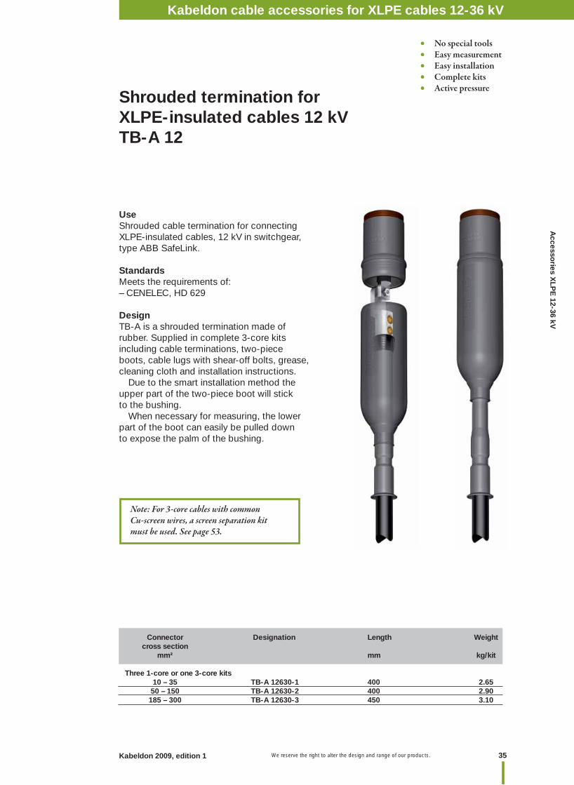
Shrouded termination for XLPE-insulated cables 12 kV TB-A 12
UseShrouded cable termination for connecting XLPE-insulated cables, 12 kV in switchgear, type ABB SafeLink.
StandardsMeets the requirements of:– CENELEC, HD 629
DesignTB-A is a shrouded termination made of rubber. Supplied in complete 3-core kits including cable terminations, two-piece boots, cable lugs with shear-off bolts, grease, cleaning cloth and installation instructions. Due to the smart installation method the upper part of the two-piece boot will stick to the bushing. When necessary for measuring, the lower part of the boot can easily be pulled down to expose the palm of the bushing.
Connector Designation Length Weight cross section mm² mm kg/kit
Three 1-core or one 3-core kits 10 – 35 TB-A 12630-1 400 2.65 50 – 150 TB-A 12630-2 400 2.90 185 – 300 TB-A 12630-3 450 3.10
• No special tools• Easy measurement • Easy installation• Complete kits• Active pressure
Note: For 3-core cables with common Cu-screen wires, a screen separation kit must be used. See page 53.
Kabeldon cable accessories for XLPE cables 12-36 kV
We reserve the right to alter the design and range of our products.36 Kabeldon 2009, edition 1
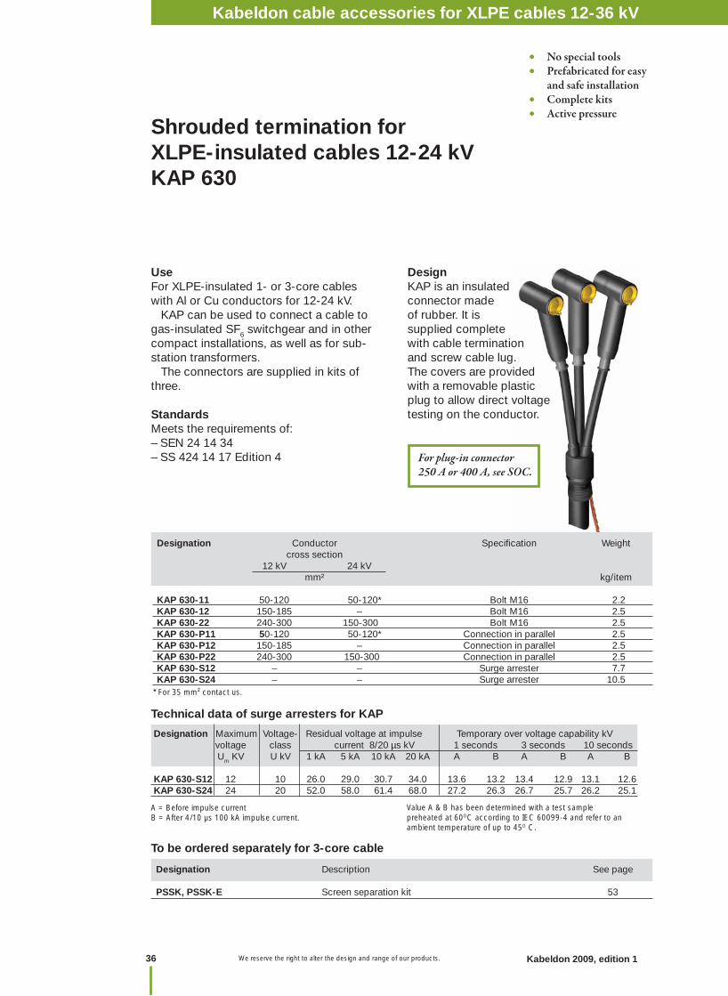
Shrouded termination for XLPE-insulated cables 12-24 kV KAP 630
UseFor XLPE-insulated 1- or 3-core cables with Al or Cu conductors for 12-24 kV. KAP can be used to connect a cable to gas-insulated SF6 switchgear and in other compact installations, as well as for sub-station transformers. The connectors are supplied in kits of three.
StandardsMeets the requirements of:– SEN 24 14 34– SS 424 14 17 Edition 4
Designation Conductor Specifi cation Weight cross section 12 kV 24 kV mm² kg/item
KAP 630-11 50-120 50-120* Bolt M16 2.2KAP 630-12 150-185 – Bolt M16 2.5 KAP 630-22 240-300 150-300 Bolt M16 2.5KAP 630-P11 50-120 50-120* Connection in parallel 2.5KAP 630-P12 150-185 – Connection in parallel 2.5KAP 630-P22 240-300 150-300 Connection in parallel 2.5 KAP 630-S12 – – Surge arrester 7.7KAP 630-S24 – – Surge arrester 10.5
* For 35 mm² contact us.
Designation Description See page PSSK, PSSK-E Screen separation kit 53
To be ordered separately for 3-core cable
• No special tools• Prefabricated for easy and safe installation• Complete kits• Active pressure
DesignKAP is an insulated connector made of rubber. It is supplied complete with cable termination and screw cable lug. The covers are provided with a removable plastic plug to allow direct voltage testing on the conductor.
Designation Maximum Voltage- Residual voltage at impulse Temporary over voltage capability kV voltage class current 8/20 µs kV 1 seconds 3 seconds 10 seconds Um KV U kV 1 kA 5 kA 10 kA 20 kA A B A B A B
KAP 630-S12 12 10 26.0 29.0 30.7 34.0 13.6 13.2 13.4 12.9 13.1 12.6KAP 630-S24 24 20 52.0 58.0 61.4 68.0 27.2 26.3 26.7 25.7 26.2 25.1
A = Before impulse currentB = After 4/10 µs 100 kA impulse current.
Technical data of surge arresters for KAP
Value A & B has been determined with a test sample preheated at 60OC according to IEC 60099-4 and refer to an ambient temperature of up to 45O C.
For plug-in connector 250 A or 400 A, see SOC.
Kabeldon cable accessories for XLPE cables 12-36 kV
37Kabeldon 2009, edition 1 We reserve the right to alter the design and range of our products.
Accesso
ries XLP
E 12-36 kV
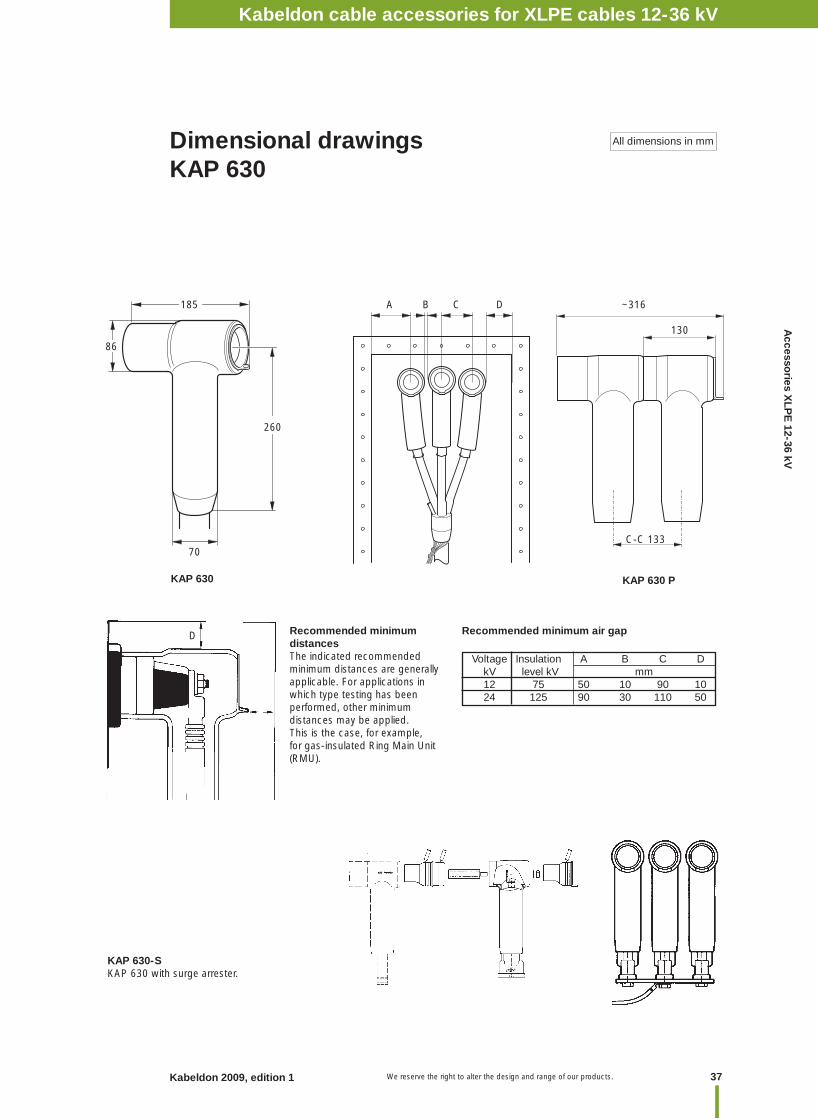
Dimensional drawingsKAP 630
All dimensions in mm
Recommended minimum distancesThe indicated recommended minimum distances are generally applicable. For applications in which type testing has been performed, other minimum distances may be applied. This is the case, for example, for gas-insulated Ring Main Unit (RMU).
Voltage Insulation A B C D kV level kV mm 12 75 50 10 90 10 24 125 90 30 110 50
Recommended minimum air gap
70
KAP 630
D
86
260
185
KAP 630 P
~316
130
C-C 133
KAP 630-SKAP 630 with surge arrester.
Kabeldon cable accessories 12-36 kV
A B C D
Kabeldon cable accessories for XLPE cables 12-36 kV

We reserve the right to alter the design and range of our products.38 Kabeldon 2009, edition 1
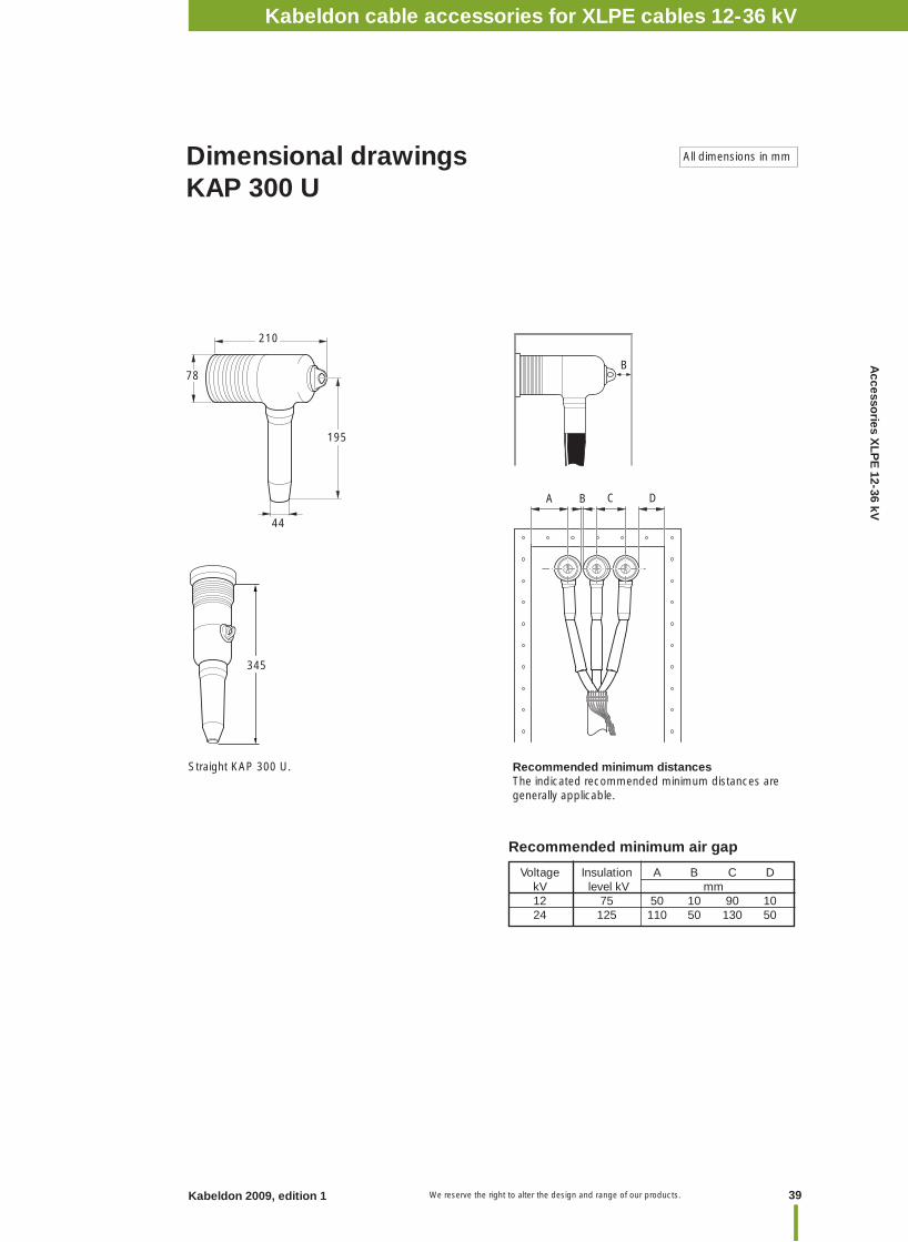
Insulating boot for 12-24 kV KAP 300 U
UseFor XLPE-insulated 1- or 3-core cables with Al or Cu conductors, for 12-24 kV. KAP 300 U is especially well suited for the renovation of, for example, oil-fi lled transformer boxes, when replacing paper-insulated cable with XLPE cable. An indoor termination type SOT (must be ordered separately) is installed together with KAP 300 U on the XLPE cable, thus insulating the connection point when the oil is drained from the cable box.KAP 300 U can also be mounted straight.
StandardsMeets the requirements of:– SEN 24 14 34– SS 424 14 17 Edition 4
DesignAn insulating boot made of rubber. The covers are fi tted with a removable plastic plug to allow direct voltage testing on the conductor. Termination and cable lug are not included.
NB. See dimensional drawings on the next page for minimum distance to earth.
Designation Conductor Specifi cation Weight cross section 12 -24 kV mm² kg/item
KAP 300 U 25-300 Bolt 2.0
Designation Description See page PSSK, PSSK-E Screen separation kit 53SKSB Screw cable lug 59SOT Cable termination 25
To be ordered separately for 3-core cable
• No special tools• Cold-applied
Kabeldon cable accessories for XLPE cables 12-36 kV
39Kabeldon 2009, edition 1 We reserve the right to alter the design and range of our products.
Accesso
ries XLP
E 12-36 kV
Dimensional drawingsKAP 300 U
All dimensions in mm
Recommended minimum distancesThe indicated recommended minimum distances are generally applicable.
Voltage Insulation A B C D kV level kV mm 12 75 50 10 90 10 24 125 110 50 130 50
Recommended minimum air gap
44
195
78
210
B
Kabeldon cable accessories 12-36 kV
CA DB
Straight KAP 300 U.
345
Kabeldon cable accessories for XLPE cables 12-36 kV
We reserve the right to alter the design and range of our products.40 Kabeldon 2009, edition 1
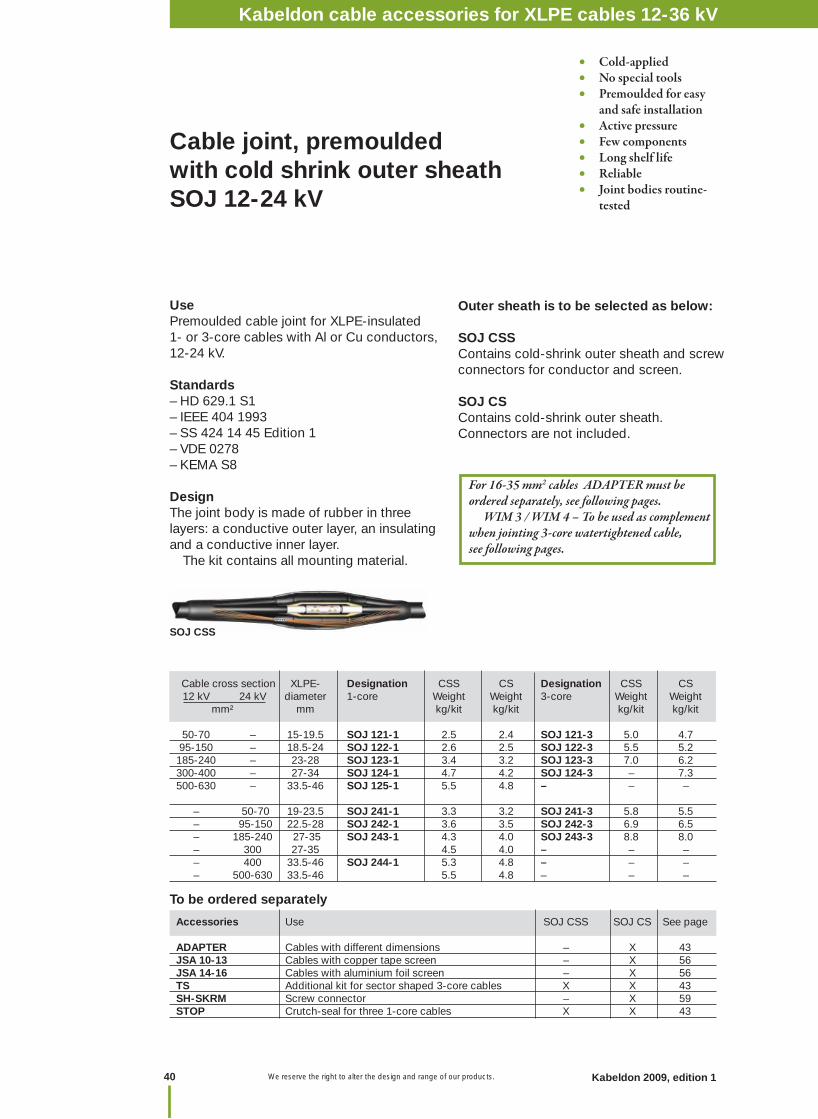
Cable joint, premoulded with cold shrink outer sheathSOJ 12-24 kV
UsePremoulded cable joint for XLPE-insulated 1- or 3-core cables with Al or Cu conductors, 12-24 kV.
Standards– HD 629.1 S1 – IEEE 404 1993– SS 424 14 45 Edition 1– VDE 0278– KEMA S8
DesignThe joint body is made of rubber in three layers: a conductive outer layer, an insulating and a conductive inner layer. The kit contains all mounting material.
Outer sheath is to be selected as below:
SOJ CSS Contains cold-shrink outer sheath and screw connectors for conductor and screen.
SOJ CS Contains cold-shrink outer sheath.Connectors are not included.
• Cold-applied• No special tools• Premoulded for easy and safe installation• Active pressure• Few components• Long shelf life• Reliable• Joint bodies routine- tested
Cable cross section XLPE- Designation CSS CS Designation CSS CS 12 kV 24 kV diameter 1-core Weight Weight 3-core Weight Weight mm² mm kg/kit kg/kit kg/kit kg/kit 50-70 – 15-19.5 SOJ 121-1 2.5 2.4 SOJ 121-3 5.0 4.7 95-150 – 18.5-24 SOJ 122-1 2.6 2.5 SOJ 122-3 5.5 5.2 185-240 – 23-28 SOJ 123-1 3.4 3.2 SOJ 123-3 7.0 6.2 300-400 – 27-34 SOJ 124-1 4.7 4.2 SOJ 124-3 – 7.3 500-630 – 33.5-46 SOJ 125-1 5.5 4.8 – – –
– 50-70 19-23.5 SOJ 241-1 3.3 3.2 SOJ 241-3 5.8 5.5 – 95-150 22.5-28 SOJ 242-1 3.6 3.5 SOJ 242-3 6.9 6.5 – 185-240 27-35 SOJ 243-1 4.3 4.0 SOJ 243-3 8.8 8.0 – 300 27-35 4.5 4.0 – – – – 400 33.5-46 SOJ 244-1 5.3 4.8 – – – – 500-630 33.5-46 5.5 4.8 – – –
To be ordered separately
Kabeldon cable accessories 12-36 kV
SOJ CSS
For 16-35 mm2 cables ADAPTER must be ordered separately, see following pages. WIM 3 / WIM 4 – To be used as complement when jointing 3-core watertightened cable, see following pages.
Accessories Use SOJ CSS SOJ CS See page ADAPTER Cables with different dimensions – X 43JSA 10-13 Cables with copper tape screen – X 56JSA 14-16 Cables with aluminium foil screen – X 56TS Additional kit for sector shaped 3-core cables X X 43SH-SKRM Screw connector – X 59STOP Crutch-seal for three 1-core cables X X 43
Kabeldon cable accessories for XLPE cables 12-36 kV
41Kabeldon 2009, edition 1 We reserve the right to alter the design and range of our products.
Accesso
ries XLP
E 12-36 kV
For 16-35 mm2 cables, ADAPTER must be ordered separately, see the table below!
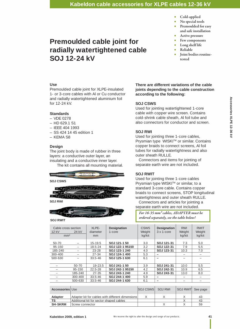
Premoulded cable joint for radially watertightened cable SOJ 12-24 kV
UsePremoulded cable joint for XLPE-insulated 1- or 3-core cables with Al or Cu conductor and radially watertightened aluminium foil for 12-24 kV.
Standards – VDE 0278– HD 629.1 S1 – IEEE 404 1993– SS 424 14 45 edition 1– KEMA S8
DesignThe joint body is made of rubber in three layers: a conductive outer layer, an insulating and a conductive inner layer. The kit contains all mounting material.
There are different variations of the cable joints depending to the cable construction according to the following:
SOJ CSWSUsed for jointing watertightened 1-core cable with copper wire screen. Contains cold-shrink cable sheath, Al foil tube and also connectors for conductor and screen.
SOJ RWIUsed for jointing three 1-core cables, Prysmian type WISKITM or similar. Contains copper braids to connect screens, Al foil tubes for radially watertightness and also outer sheath RULLE. Connectors and items for jointing of separate earth wire are not included.
SOJ RWITUsed for jointing three 1-core cables Prysmian type WISKITM or similar, to a standard 3-core cable. Contains copper braids to connect screens, STOP longitudinal watertightness and outer sheath RULLE. Connectors and articles for jointing a separate earth wire are not included.
Accessories Use SOJ CSWS SOJ RWI SOJ RWIT See page
Adapter Adapter kit for cables with different dimensions X X X 43TS Additional kit for sector shaped cables X 43SH-SKRM Screw connector X X 59
Cable cross section XLPE- Designation CSWS Designation RWI RWIT 12 kV 24 kV diameter 1-core Weight 3 x 1-core Weight Weight mm² mm kg/kit kg/kit kg/kit 50-70 – 15-19.5 SOJ 121-1 50 3.0 SOJ 121-31 7.3 5.0 95-150 – 18.5-24 SOJ 122-1 95150 3.2 SOJ 122-31 7.9 5.5 185-240 – 23-28 SOJ 123-1 240 4.0 SOJ 123-31 10.3 7.0 300-400 – 27-34 SOJ 124-1 400 5.3 – – – 500-630 – 33.5-46 SOJ 125-1 630 6.1 – – –
– 50-70 19-23.5 SOJ 241-1 50 3.9 SOJ 241-31 10.0 5.5 – 95-150 22.5-28 SOJ 242-1 95150 4.2 SOJ 242-31 10.9 6.5 – 185-240 27-35 SOJ 243-1 240 4.9 SOJ 243-31 13.0 8.0 – 300-400 33.5-46 SOJ 244-1 400 5.9 – – – – 500-630 33.5-46 SOJ 244-1 630 6.1 – – –
SOJ RWIT
SOJ CSWS
SOJ RWI
• Cold-applied• No special tools• Premoulded for easy and safe installation• Active pressure• Few components• Long shelf life• Reliable• Joint bodies routine- tested
Kabeldon cable accessories for XLPE cables 12-36 kV

We reserve the right to alter the design and range of our products.42 Kabeldon 2009, edition 1
Premoulded cable joint with or without outer sheath, RULLESOJ 12-24 kV
UsePremoulded cable joint for XLPE-insulated 1- or 3-core cables with Al or Cu conductor for 12-24 kV.
Standards – HD 629.1 S1 – SS 424 14 45 edition1– VDE 0278– KEMA S8– IEEE 404 1993
DesignThe joint body is made of rubber in three layers: a conductive outer layer, an insulating and a conductive inner layer. The kit contains all mounting material.
Outer sheath is to be selected as below:
SOJ RContains outer sheath RULLE, a two-layer tape of EPDM-rubber and mastic, which is wrapped around the joint. Connectors are not included.
SOJ SLSupplied without outer sheath. NB! An outer sheath approved by us must be added, for example type ARM. Connectors are not included.
Cable cross section XLPE- Designation R Designation SL Designation R Designation SL 12 kV 24 kV diameter 1-core Weight Weight 3-core Weight Weight mm² mm kg/kit kg/kit kg/kit kg/kit 50-70 – 15-19.5 SOJ 121-1 2.6 SOJ 121-1 SL 1.0 SOJ 121-3 4.7 SOJ 121-3 SL 2.0 95-150 – 18.5-24 SOJ 122-1 3.0 SOJ 122-1 SL 1.1 SOJ 122-3 5.6 SOJ 122-3 SL 2.3 185-240 – 23-28 SOJ 123-1 3.1 SOJ 123-1 SL 1.2 SOJ 123-3 6.4 SOJ 123-3 SL 2.7300-400 – 27-34 SOJ 124-1 4.3 SOJ 124-1 SL 1.6 SOJ 124-3 8.9 SOJ 124-3 SL 4.2 500-630 – 33.5-46 SOJ 125-1 5.9 SOJ 125-1 SL 2.2 – – – – – 50-70 19-23.5 SOJ 241-1 3.2 SOJ 241-1 SL 1.3 SOJ 241-3 6.2 SOJ 241-3 SL 2.8 – 95-150 22.5-28 SOJ 242-1 3.9 SOJ 242-1 SL 1.5 SOJ 242-3 7.0 SOJ 242-3 SL 3.4 – 185-300 27-35 SOJ 243-1 4.5 SOJ 243-1 SL 1.8 SOJ 243-3 9.1 SOJ 243-3 SL 4.5 – 400-630 33.5-46 SOJ 244-1 6.4 SOJ 244-1 SL 2.2 – – – –
Kabeldon cable accessories 12-36 kV
SOJ R
• Cold-applied• No special tools• Premoulded for easy and safe installation• Active pressure• Few components• Long shelf life• Reliable• Joint bodies routine- tested
For 16-35 mm2 cables ADAPTER must be ordered separately, see the table below! WIM 3 / WIM 4 – To be used as complement when jointing 3-core watertightened cable, see the table below.
Accessories Use SOJ R SOJ SL See page
Adapter Cables with different dimensions X X 43JSA 10-13 Cables with copper tape screen X X 56JSA 14-16 Cables with aluminium foil screen X X 56TS Additional kit for sector shaped 3-core cables X X 43WIM Diffusion seal X X 44ARM Armouring kit – X 57STOP Branch seal for three 1-core cables X – 43SH-SKRM Screw connector X X 59
Kabeldon cable accessories for XLPE cables 12-36 kV
43Kabeldon 2009, edition 1 We reserve the right to alter the design and range of our products.
Accesso
ries XLP
E 12-36 kV
Designation Fitting joint Minimum XLPE Weight conductor cross section diameter mm2 mm kg/item
ADAPTER 1* SOJ 121, 241 10 Minimum 10 0.1 ADAPTER 2 SOJ 122 50 15.0-19.5 0.1 ADAPTER 3 SOJ 123 95 18.5-24.0 0.1 SOJ 242 50 19.0-23.5 0.1 ADAPTER 4 SOJ 124 185 23.0-28.0 0.1 SOJ 243 95 22.5-28.0 0.1 ADAPTER 5 SOJ 125 300 27.0-34.0 0.1 SOJ 244 185 27.0-35.0 0.1ADAPTER 6 SOJ 125 185 23.0-28.0 0.1 SOJ 244 95 22.5-28.0 0.1
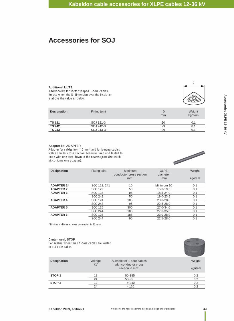
Accessories for SOJ
Adapter kit, ADAPTERAdapter for cables from 10 mm2 and for jointing cables with a smaller cross section. Manufactured and tested to cope with one step down to the nearest joint size (each kit contains one adapter).
* Minimum diameter over connector is 12 mm.
Designation Voltage Suitable for 1-core cables Weight kV with conductor cross section in mm2 kg/item
STOP 1 12 50-185 0.2 24 50-95 0.2STOP 2 12 > 240 0.2 24 > 120 0.2
Crutch seal, STOPFor sealing when three 1-core cables are jointed to a 3-core cable.
D
Designation Fitting joint D Weight mm kg/item TS 121 SOJ 121-3 20 0.1TS 242 SOJ 242-3 29 0.1 TS 243 SOJ 243-3 39 0.1
Additional kit TSAdditional kit for sector shaped 3-core cables, for use when the D-dimension over the insulation is above the value as below.
Kabeldon cable accessories for XLPE cables 12-36 kV
We reserve the right to alter the design and range of our products.44 Kabeldon 2009, edition 1
Accessories Type of jointing / cable type CSS CS R SL RWI RWIT See page
TS Additional kit for sector shaped 3-core cables X X X X X 43Adapter Cables with different dimensions X X X X X X 43STOP 3 x 1-core to a 3-core X 43WIM Radial watertightness cable X X X 44JSA 10-13 Cable with copper tape screen X X X 56JSA 14-16 Cable with aluminium foil screen only X X X 56ARM Armoured cable or when extra mechanical protection is required X 57SH-SKRM Screw connector X X X X X 59
To be ordered separately
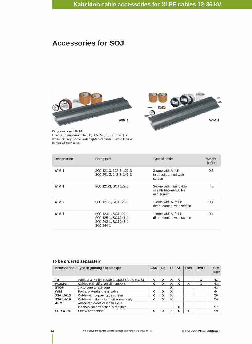
Diffusion seal, WIMUsed as complement to SOJ CS, SOJ CSS or SOJ R when jointing 3-core watertightened cables with diffussion barrier of aluminium.
Designation Fitting joint Type of cable Weight kg/kit
WIM 3 SOJ 121-3, 122-3, 123-3, 3-core with Al foil 0.5 SOJ 241-3, 242-3, 243-3 in direct contact with screen
WIM 4 SOJ 121-3, SOJ 122-3 3-core with inner cable 4.0 sheath between Al foil and screen
WIM 5 SOJ 121-1, SOJ 122-1 1-core with Al-foil in 0,4 direct contact with screen
WIM 6 SOJ 123-1, SOJ 124-1, 1-core with Al-foil in 0,4 SOJ 125-1, SOJ 241-1, direct contact with screen SOJ 242-1, SOJ 243-1, SOJ 244-1
Accessories for SOJ
WIM 3 WIM 4
Kabeldon cable accessories 12-36 kVKabeldon cable accessories for XLPE cables 12-36 kV
45Kabeldon 2009, edition 1 We reserve the right to alter the design and range of our products.
Accesso
ries XLP
E 12-36 kV
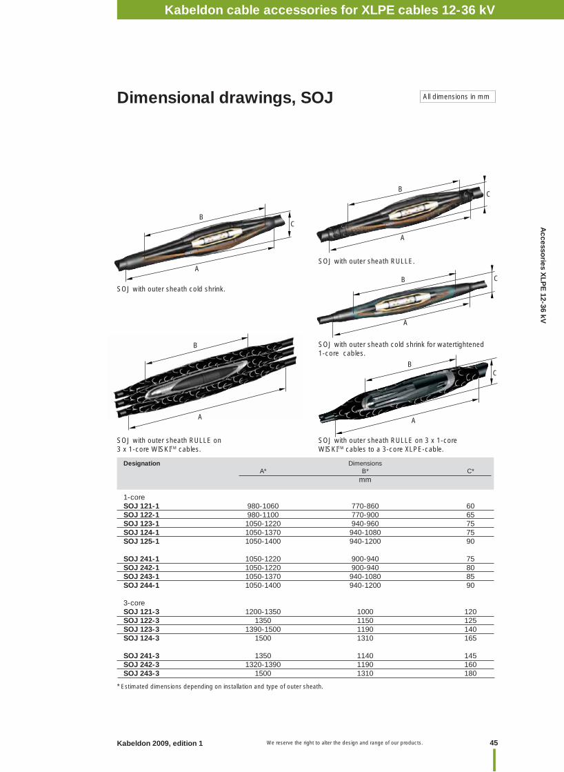
Dimensional drawings, SOJ All dimensions in mm
Designation Dimensions A* B* C* mm
1-coreSOJ 121-1 980-1060 770-860 60SOJ 122-1 980-1100 770-900 65SOJ 123-1 1050-1220 940-960 75SOJ 124-1 1050-1370 940-1080 75SOJ 125-1 1050-1400 940-1200 90 SOJ 241-1 1050-1220 900-940 75SOJ 242-1 1050-1220 900-940 80SOJ 243-1 1050-1370 940-1080 85SOJ 244-1 1050-1400 940-1200 90
3-core SOJ 121-3 1200-1350 1000 120SOJ 122-3 1350 1150 125SOJ 123-3 1390-1500 1190 140SOJ 124-3 1500 1310 165 SOJ 241-3 1350 1140 145SOJ 242-3 1320-1390 1190 160SOJ 243-3 1500 1310 180
* Estimated dimensions depending on installation and type of outer sheath.
SOJ with outer sheath cold shrink.
SOJ with outer sheath RULLE.
SOJ with outer sheath RULLE on 3 x 1-core WISKITM cables.
SOJ with outer sheath RULLE on 3 x 1-core WISKITM cables to a 3-core XLPE-cable.
SOJ with outer sheath cold shrink for watertightened 1-core cables.
B
A
BC
A
B
A
C
B
A
C
B
A
C
Kabeldon cable accessories for XLPE cables 12-36 kV
We reserve the right to alter the design and range of our products.46 Kabeldon 2009, edition 1
Cable joint, tapeSMXB 12-36 kV
Designation Weight Designation Weight kg/item kg/item
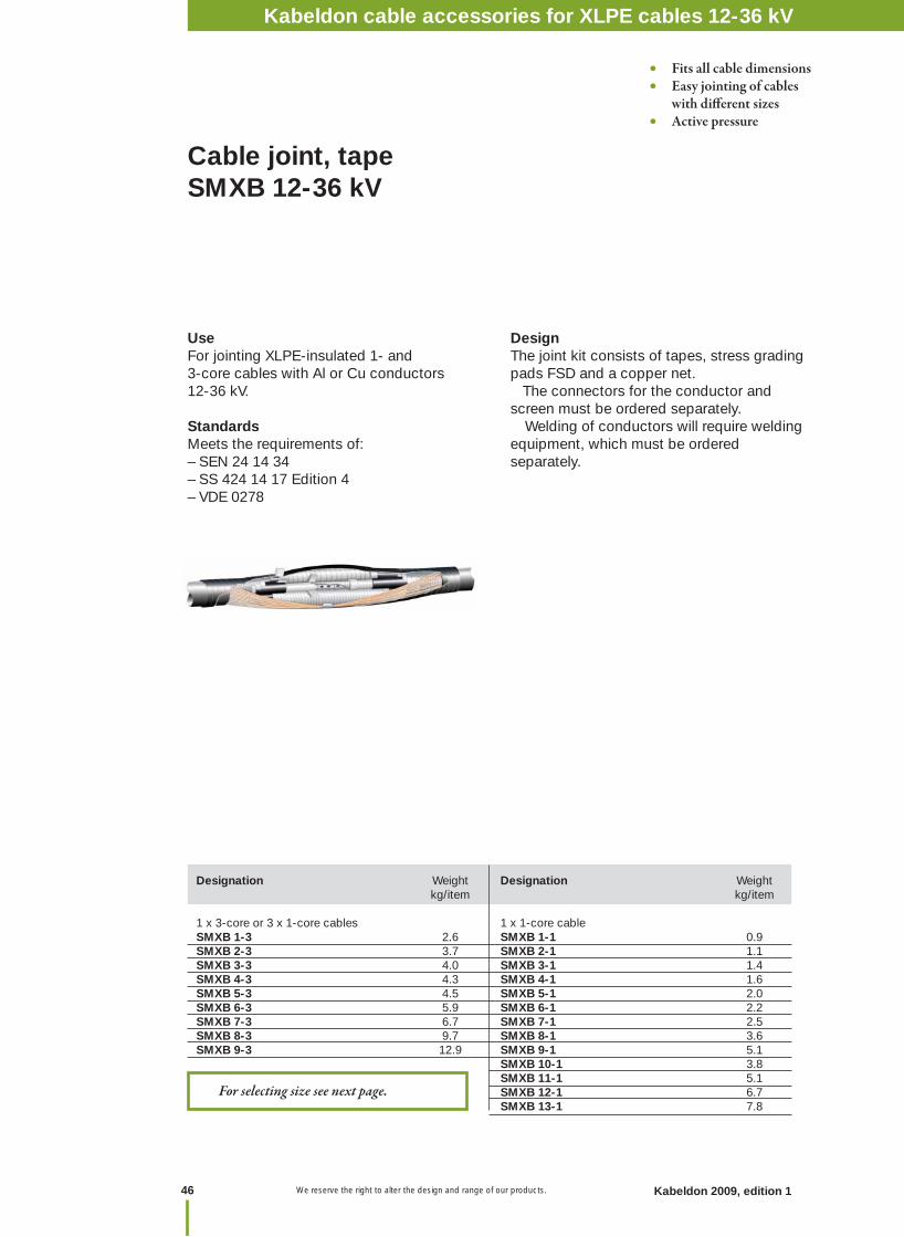
1 x 3-core or 3 x 1-core cables 1 x 1-core cableSMXB 1-3 2.6 SMXB 1-1 0.9 SMXB 2-3 3.7 SMXB 2-1 1.1 SMXB 3-3 4.0 SMXB 3-1 1.4SMXB 4-3 4.3 SMXB 4-1 1.6 SMXB 5-3 4.5 SMXB 5-1 2.0SMXB 6-3 5.9 SMXB 6-1 2.2SMXB 7-3 6.7 SMXB 7-1 2.5SMXB 8-3 9.7 SMXB 8-1 3.6 SMXB 9-3 12.9 SMXB 9-1 5.1 SMXB 10-1 3.8 SMXB 11-1 5.1 SMXB 12-1 6.7 SMXB 13-1 7.8
UseFor jointing XLPE-insulated 1- and3-core cables with Al or Cu conductors12-36 kV.
StandardsMeets the requirements of:– SEN 24 14 34– SS 424 14 17 Edition 4– VDE 0278
DesignThe joint kit consists of tapes, stress grading pads FSD and a copper net. The connectors for the conductor and screen must be ordered separately. Welding of conductors will require welding equipment, which must be ordered separately.
• Fits all cable dimensions• Easy jointing of cables with diff erent sizes• Active pressure
For selecting size see next page.
Kabeldon cable accessories 12-36 kVKabeldon cable accessories for XLPE cables 12-36 kV

47Kabeldon 2009, edition 1 We reserve the right to alter the design and range of our products.
Accesso
ries XLP
E 12-36 kV
Recommendation tables for SMXB
For compression of aluminium conductors
Voltage Insulation Cross section mm² thickness 10 25 35 50 70 95 120 150 185 240 300 400 500 630 kV mm
One 3-core or Cable joint SMXB No. three 1-core cables
12 3.4 1 1 1 1 1 2 2 2 3 3 6 7 7 8 24 5.5 2 3 4 4 4 5 5 6 6 6 8 8 8 9 One 1-core cable 36 8.0 – 10 10 10 10 10 10 10 11 11 11 11 11 12
Voltage Insulation Cross section mm² thickness 25 35 50 70 95 120 150 185 240 300 400 500 630 800 1200 kV mm One 3-core or Cable joint SMXB No. three 1-core cables 12 3.4 1 1 1 1 1 1 2 2 3 3 7 7 7 – – 24 5.5 3 3 3 3 3 5 5 5 6 6 7 8 8 – –One 1-core cable 36 8.0 10 10 10 10 10 10 10 11 11 11 11 11 11 13 13
For compression of copper conductors
For thermite welding of aluminium or copper conductors
Voltage Insulation Cross section mm² thickness 400 500 630 800 1000 1200 kV mm One 3-core or Cable joint SMXB No. three 1-core cables 12 3.4 7 7 7 – – – 24 5.5 8 8 8 – – – One 1-core cable 36 8.0 11 11 11 11 12 12
Kabeldon cable accessories for XLPE cables 12-36 kV

We reserve the right to alter the design and range of our products.48 Kabeldon 2009, edition 1
WIMDiffusion seal kits for restoring radial watertightness on cables with diffusion barrier of aluminium.
Designation Fitting joint Type of cable Weight kg/kit
WIM 1 SMXB 1-1, 2-1, 3-1, 4-1 1-core with Al foil 0.5
WIM 2 SMXB 5-1, 6-1, 7-1, 8-1, 9-1, 10-1, 11-1, 12-1 1-core with Al foil 0.5
WIM 3 SMXB 1-3, 2-3, 3-3, 4-3 3-core with Al foil 0.5 SMXB 5-3, 6-3 in direct contact with screen WIM 4 SMXB 1-3, 2-3, 4-3, 5-3 3-core with inner 4.0 sheath between Al foil and screen
WIM 3 WIM 4
Designation Description Connector Only crimp connectors can be used Welding equipment Welding of conductors
Accessories for SMXB
Designation Voltage Suitable for 1-core cables Weight with conductor cross kV section in mm² kg/item
STOP 1 12 50-185 0.2 24 50-95 0.2STOP 2 12 > 240 0.2 24 >120 0.2
STOPCrutch seal for sealing when 3 x 1-core cables are jointed to a 3-core cable.
To be ordered separately
Kabeldon cable accessories for XLPE cables 12-36 kV
49Kabeldon 2009, edition 1 We reserve the right to alter the design and range of our products.
Accesso
ries XLP
E 12-36 kV
Cable cabinet 250 A HDC 250
Designation XLPE- Conductor Dimensions Weight diameter cross section Height Width Depth mm mm² mm kg /unit
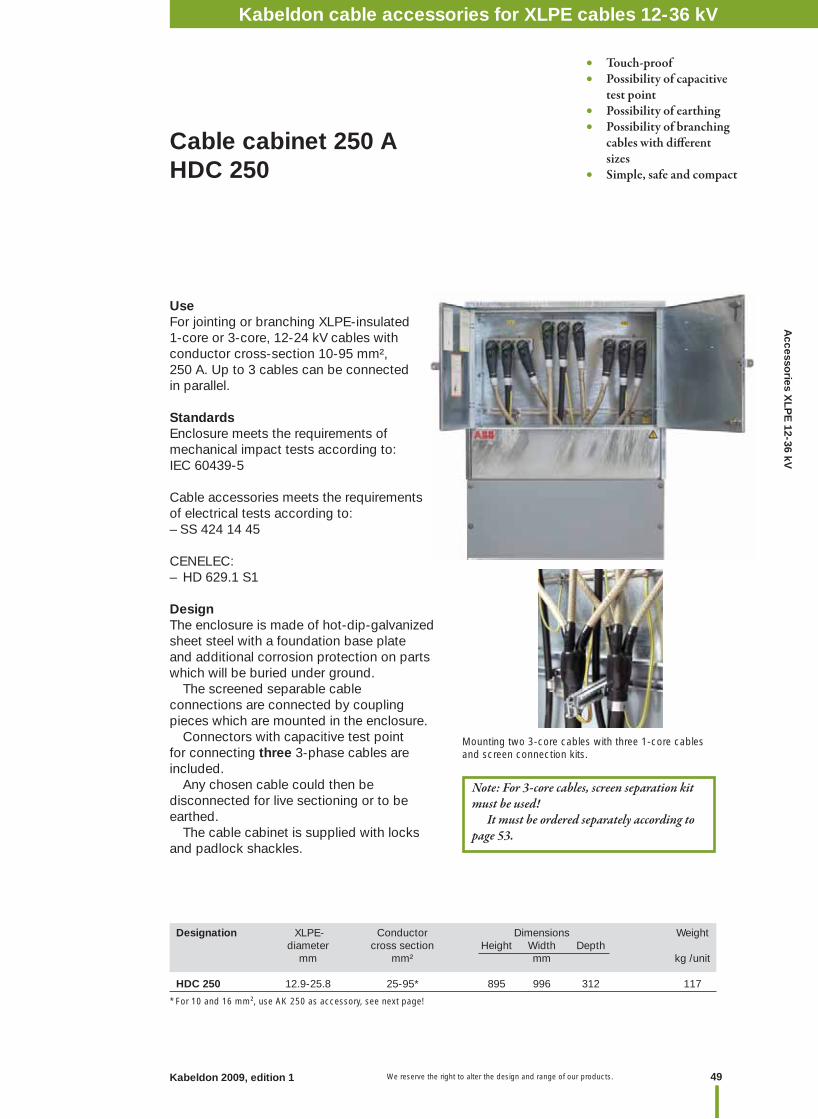
HDC 250 12.9-25.8 25-95* 895 996 312 117
UseFor jointing or branching XLPE-insulated 1-core or 3-core, 12-24 kV cables with conductor cross-section 10-95 mm², 250 A. Up to 3 cables can be connected in parallel.
StandardsEnclosure meets the requirements of mechanical impact tests according to:IEC 60439-5
Cable accessories meets the requirements of electrical tests according to:– SS 424 14 45
CENELEC:– HD 629.1 S1
DesignThe enclosure is made of hot-dip-galvanized sheet steel with a foundation base plate and additional corrosion protection on parts which will be buried under ground. The screened separable cable connections are connected by coupling pieces which are mounted in the enclosure. Connectors with capacitive test point for connecting three 3-phase cables are included. Any chosen cable could then be disconnected for live sectioning or to be earthed. The cable cabinet is supplied with locks and padlock shackles.
• Touch-proof• Possibility of capacitive test point• Possibility of earthing• Possibility of branching cables with diff erent sizes• Simple, safe and compact
Kabeldon cable accessories 12-36 kV
Note: For 3-core cables, screen separation kit must be used! It must be ordered separately according to page 53.
Mounting two 3-core cables with three 1-core cables and screen connection kits.
* For 10 and 16 mm², use AK 250 as accessory, see next page!
Kabeldon cable accessories for XLPE cables 12-36 kV

We reserve the right to alter the design and range of our products.50 Kabeldon 2009, edition 1
Accessories for cable cabinet HDC 250
Ø 13
35
UKRA 90Universal clamp.
MA 250Measurement adapter used for mega measurements and to perform different measurements up to 5 kV DC, for example determination of phases.
KA 250Transversal anchor bar.
PSSK: for cables with Cu-wire screen, heat-shrink.PSSK E: for Ericsson's cables with Al-wire screen, heat-shrink.
IH SOC 250 TPInsulating hood made of fl exible rubber with outer conductive layer and an already installed insulating hood. To be mounted at the bushing in HDC 250 for insulation when a cable is temporary disconnected and remaining cables are under voltage.
JP 250-HDCEarth circuit connector for short-circuit protective earthing. To be mounted on a disconnected connector. 3 pieces in a case.
AK 250Accessory kit for SOC 250, allowing installation on smaller cables with conductor cross section 10-16 mm2. The kit consists of three adapters and three inserts. Every insert is made of tinned copper and is clamped to the conductor with pliers before it is installed in the connector.
IP 250Screened insulating plug for installation in the connector so that the cable can be energized even when the connection is disconnected.
* Special screen separation for Ericsson’s 3-core cable with Al-wire screen.
Designation Description Qty Weight kit kg/unit
IP 250 Screened insulating plug 1 0.8JP 250-HDC Earthing circuit connector 3 3.0AK 250 Accessories kit for cables 10-16 mm² 3 2.2 IH SOC 250 TP Insulating hood 3 2.3MA 250 Measurement adapter 1 0.3KA 250 Busbar 1 0.5PSSK 1 heat shrink Screen separation kit for 3-core cable 10-70/12 kV, 10-35/24 kV 1 1.0PSSK 1 E heat shrink* Screen separation kit for 3-core cable 10-70/12 kV, 10-35/24 kV 1 1.0UKRA 90 Clamp for fi xing cables 1 0.23
Kabeldon cable accessories for XLPE cables 12-36 kV
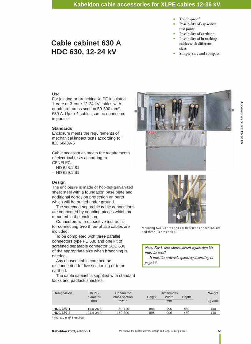
51Kabeldon 2009, edition 1 We reserve the right to alter the design and range of our products.
Accesso
ries XLP
E 12-36 kV
Cable cabinet 630 AHDC 630, 12-24 kV
Designation XLPE- Conductor Dimensions Weight diameter cross section Height Width Depth mm mm² * mm kg /unit
HDC 630-1 15.0-26.8 50-120 895 996 450 140HDC 630-2 21.4-34.9 150-300 895 996 450 140
• Touch-proof• Possibility of capacitive test point• Possibility of earthing• Possibility of branching cables with diff erent sizes• Simple, safe and compact
UseFor jointing or branching XLPE-insulated 1-core or 3-core 12-24 kV cables with conductor cross section 50-300 mm², 630 A. Up to 4 cables can be connected in parallel.
StandardsEnclosure meets the requirements of mechanical impact tests according to:IEC 60439-5
Cable accessories meets the requirements of electrical tests according to:CENELEC:– HD 628.1 S1– HD 629.1 S1
DesignThe enclosure is made of hot-dip-galvanized sheet steel with a foundation base plate and additional corrosion protection on parts which will be buried under ground. The screened separable cable connections are connected by coupling pieces which are mounted in the enclosure. Connectors with capacitive test point for connecting two three-phase cables are included. To be completed with three parallel connectors type PC 630 and one kit of screened separable connector SOC 630 of the appropriate size when branching is needed. Any chosen cable can then be disconnected for live sectioning or to be earthed. The cable cabinet is supplied with standard locks and padlock shackles.
Kabeldon cable accessories 12-36 kV
Note: For 3-core cables, screen separation kit must be used! It must be ordered separately according to page 53.
Mounting two 3-core cables with screen connection kits and three 1-core cables.
* 400-630 mm² if required.
Kabeldon cable accessories for XLPE cables 12-36 kV

We reserve the right to alter the design and range of our products.52 Kabeldon 2009, edition 1
Accessories for cable cabinet HDC 630
Designation Description Qty Weight a kit kg/unit
SOC 630-1 Screened separable connector for branching 3 2.2SOC 630-2 Screened separable connector for branching 3 2.2SOC 250 TP Connector with capacitive test point 3 2.2PC 630 For connecting of cable for branch seal 1 1.1 PC 630 L For connecting of cable for branch seal 1 1.4IP 630 Insulatated plug 1 0.8JP 630-HDC Earthing circuit connector 3 1.3MA 630 Measurement adapter 1 0.1JPA 630-HDC Earthing-for-work device 3 1.9PSSK 1 Screen separation 3-core cable 10-70/12 kV, 10-35/24 kV 1 1.0PSSK 2 Screen separation 3-core cable 95-300/12 kV, 50-300/24 kV 1 1.0PSSK 1 E * Screen separation 3-core cable 10-70/12 kV, 10-35/24 kV 1 1.0PSSK 2 E * Screen separation 3-core cable 95-300/12 kV, 50-300/24 kV 1 1.0PC 630/250 Parallel connector between SOC 630 and SOC 250 3 3.0HBS 10 Hex bit socket 1 0.1IH SOC 630 Insulating hood 3 5.2JPA V Tool for earthing-for-work device 1 1.8KA 630 Busbar, add two when using 1-core cables 1 0.8UKRA 90 Clamp for fi xing cables 1 0.23
PSSK: for cables with Cu-wire screen, heat shrink.PSSK E: for Ericsson's cables with Al-wire screen, heat shrink.
SOC 630Screened separable connector.
PC 630Parallel coupling piece.Replaces the plug in SOC 630-1 and -2 when making a parallel connection to SOC 630-1/2/3/4/5.
JP 630-HDCEarthing device for short-circuit protective earthing. To be mounted to disconnected connector. 3 pieces in a case.
JPA 630-HDCEarthing-for-work device. 3 pieces in a case.
KA 630Transversal anchor bar.
PC 630/250Connector for connecting a SOC 250, in parallel with a previously mounted SOC 630.
MA 630Measurement adapter used for mega measurements and to perform different measurements up to 5 kV DC, for determination of phases.
IH SOC 630Insulating sealing hood of fl exible rubber with outer conductive layer and an already installed insulating hood. To be installed in SOC instead of cable in order to temporarily insulating 630 A switchgear or transformer bushings.
IP 630Screened insulating plug for installation in the screened separable connector so that the cable can be energized even when the connector is disconnected from the switchgear or transformer.
SOC 250-TPScreened separable connector with possibility of capacitive test point. For connecting an additional cable for 250 A.
UKRA 90Universal clamp.
Ø 13
35
* Special screen separation for Ericsson’s 3-core cable with Al-wire screen.
JPA VTool for earthing-for-work device.
HBS 10Extended hex bit socket 10 mm with 1/2" drive for torque wrench. For installation of PC 630 and PC 630 L.
PC 630 LParallel coupling piece.Replaces the plug in SOC 630-3/4/5 when making a parallel connection to SOC 630-1/2/3/4/5.
Kabeldon cable accessories for XLPE cables 12-36 kV
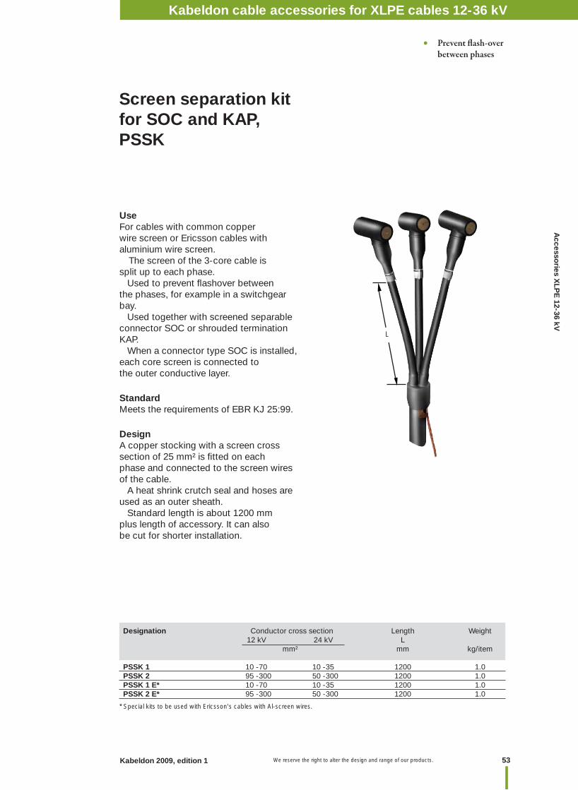
53Kabeldon 2009, edition 1 We reserve the right to alter the design and range of our products.
Accesso
ries XLP
E 12-36 kV
Designation Conductor cross section Length Weight 12 kV 24 kV L mm² mm kg/item PSSK 1 10 -70 10 -35 1200 1.0PSSK 2 95 -300 50 -300 1200 1.0PSSK 1 E* 10 -70 10 -35 1200 1.0PSSK 2 E* 95 -300 50 -300 1200 1.0
Screen separation kit for SOC and KAP,PSSK
• Prevent fl ash-over between phases
UseFor cables with common copper wire screen or Ericsson cables with aluminium wire screen. The screen of the 3-core cable is split up to each phase. Used to prevent fl ashover between the phases, for example in a switchgear bay. Used together with screened separable connector SOC or shrouded termination KAP. When a connector type SOC is installed, each core screen is connected to the outer conductive layer.
StandardMeets the requirements of EBR KJ 25:99.
DesignA copper stocking with a screen cross section of 25 mm² is fi tted on each phase and connected to the screen wires of the cable. A heat shrink crutch seal and hoses are used as an outer sheath. Standard length is about 1200 mm plus length of accessory. It can also be cut for shorter installation.
* Special kits to be used with Ericsson's cables with Al-screen wires.
L
Kabeldon cable accessories for XLPE cables 12-36 kV
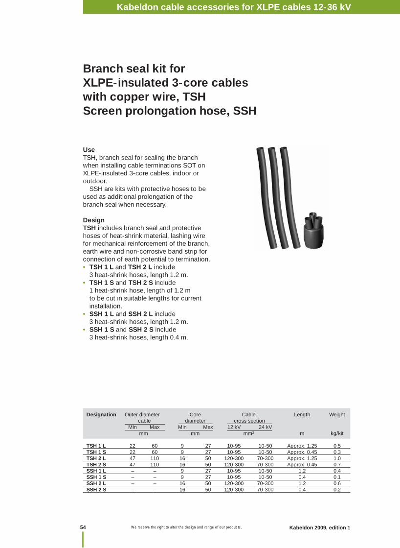
We reserve the right to alter the design and range of our products.54 Kabeldon 2009, edition 1
Branch seal kit for XLPE-insulated 3-core cables with copper wire, TSH Screen prolongation hose, SSH
UseTSH, branch seal for sealing the branch when installing cable terminations SOT on XLPE-insulated 3-core cables, indoor or outdoor. SSH are kits with protective hoses to be used as additional prolongation of the branch seal when necessary.
DesignTSH includes branch seal and protective hoses of heat-shrink material, lashing wire for mechanical reinforcement of the branch, earth wire and non-corrosive band strip for connection of earth potential to termination.• TSH 1 L and TSH 2 L include 3 heat-shrink hoses, length 1.2 m.• TSH 1 S and TSH 2 S include 1 heat-shrink hose, length of 1.2 m to be cut in suitable lengths for current installation.• SSH 1 L and SSH 2 L include 3 heat-shrink hoses, length 1.2 m.• SSH 1 S and SSH 2 S include 3 heat-shrink hoses, length 0.4 m.
Designation Outer diameter Core Cable Length Weight cable diameter cross section Min Max Min Max 12 kV 24 kV mm mm mm² m kg/kit
TSH 1 L 22 60 9 27 10-95 10-50 Approx. 1.25 0.5TSH 1 S 22 60 9 27 10-95 10-50 Approx. 0.45 0.3TSH 2 L 47 110 16 50 120-300 70-300 Approx. 1.25 1.0TSH 2 S 47 110 16 50 120-300 70-300 Approx. 0.45 0.7SSH 1 L – – 9 27 10-95 10-50 1.2 0.4SSH 1 S – – 9 27 10-95 10-50 0.4 0.1SSH 2 L – – 16 50 120-300 70-300 1.2 0.6SSH 2 S – – 16 50 120-300 70-300 0.4 0.2
Kabeldon cable accessories for XLPE cables 12-36 kV
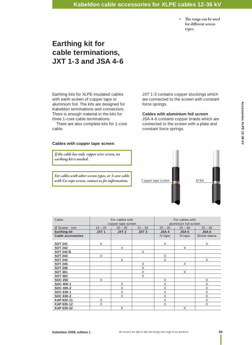
55Kabeldon 2009, edition 1 We reserve the right to alter the design and range of our products.
Accesso
ries XLP
E 12-36 kV
Earthing kits for XLPE-insulated cables with earth screen of copper tape or aluminium foil. The kits are designed for Kabeldon terminations and connectors. There is enough material in the kits for three 1-core cable terminations. There are also complete kits for 1-core cable.
Cables with copper tape screen
JXT 1-3 contains copper stockings which are connected to the screen with constant force springs.
Cables with aluminium foil screenJSA 4-6 contains copper braids which are connected to the screen with a plate and constant force springs.
If the cable has only copper wire screen, no earthing kit is needed.
Cable For cables with For cables with copper tape screen aluminium foil screenØ Screen mm 15 – 25 20 – 30 31 – 50 20 – 30 25 – 40 20 – 30Earthing kit JXT 1 JXT 2 JXT 3 JSA 4 JSA 5 JSA 6Cable accessories IV-tape IV-tape Shrink sleeve
SOT 241 X X XSOT 242 X X SOT 242 B X SOT 243 X X SOT 244 X X XSOT 245 X X SOT 246 X SOT 361 X X SOT 362 X SOC 250 X X XSOC 400-1 X X XSOC 400-2 X X XSOC 630-1 X X XSOC 630-2 X X XKAP 630-11 X X XKAP 630-12 X X XKAP 630-22 X X
Copper tape screen Al foil
Earthing kit for cable terminations, JXT 1-3 and JSA 4-6
• Th e range can be used for diff erent screen types
Kabeldon cable accessories 12-36 kV
For cables with other screen types, or 3-core cable with Cu-tape screen, contact us for information.
Kabeldon cable accessories for XLPE cables 12-36 kV
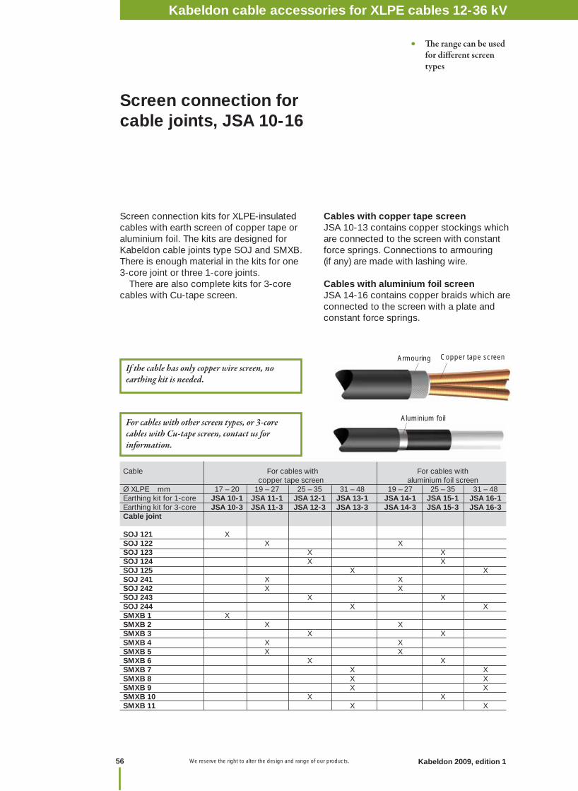
We reserve the right to alter the design and range of our products.56 Kabeldon 2009, edition 1
Screen connection kits for XLPE-insulated cables with earth screen of copper tape or aluminium foil. The kits are designed for Kabeldon cable joints type SOJ and SMXB. There is enough material in the kits for one 3-core joint or three 1-core joints. There are also complete kits for 3-core cables with Cu-tape screen.
Cables with copper tape screenJSA 10-13 contains copper stockings which are connected to the screen with constant force springs. Connections to armouring (if any) are made with lashing wire.
Cables with aluminium foil screenJSA 14-16 contains copper braids which are connected to the screen with a plate and constant force springs.
Cable For cables with For cables with copper tape screen aluminium foil screenØ XLPE mm 17 – 20 19 – 27 25 – 35 31 – 48 19 – 27 25 – 35 31 – 48Earthing kit for 1-core JSA 10-1 JSA 11-1 JSA 12-1 JSA 13-1 JSA 14-1 JSA 15-1 JSA 16-1Earthing kit for 3-core JSA 10-3 JSA 11-3 JSA 12-3 JSA 13-3 JSA 14-3 JSA 15-3 JSA 16-3Cable joint
SOJ 121 X SOJ 122 X X SOJ 123 X X SOJ 124 X X SOJ 125 X XSOJ 241 X X SOJ 242 X X SOJ 243 X X SOJ 244 X XSMXB 1 X SMXB 2 X X SMXB 3 X X SMXB 4 X X SMXB 5 X X SMXB 6 X X SMXB 7 X XSMXB 8 X XSMXB 9 X XSMXB 10 X X SMXB 11 X X
Screen connection for cable joints, JSA 10-16
• Th e range can be used for diff erent screen types
Aluminium foil
Armouring Copper tape screen
For cables with other screen types, or 3-core cables with Cu-tape screen, contact us for information.
If the cable has only copper wire screen, no earthing kit is needed.
Kabeldon cable accessories for XLPE cables 12-36 kV
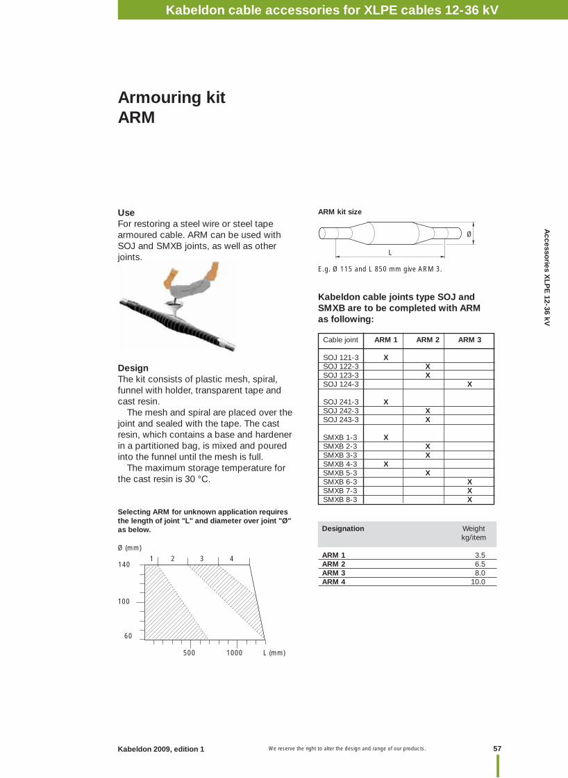
57Kabeldon 2009, edition 1 We reserve the right to alter the design and range of our products.
Accesso
ries XLP
E 12-36 kV
Selecting ARM for unknown application requires the length of joint "L" and diameter over joint "Ø" as below.
E.g. Ø 115 and L 850 mm give ARM 3.
ARM kit size
Armouring kitARM
Designation Weight kg/item
ARM 1 3.5ARM 2 6.5ARM 3 8.0ARM 4 10.0
Cable joint ARM 1 ARM 2 ARM 3
SOJ 121-3 X SOJ 122-3 XSOJ 123-3 XSOJ 124-3 X
SOJ 241-3 X SOJ 242-3 XSOJ 243-3 X
SMXB 1-3 XSMXB 2-3 XSMXB 3-3 XSMXB 4-3 XSMXB 5-3 XSMXB 6-3 XSMXB 7-3 XSMXB 8-3 X
500 1000 L (mm)
60
100
1401 2 3 4
Ø (mm)
Ø
L
Kabeldon cable joints type SOJ and SMXB are to be completed with ARM as following:
UseFor restoring a steel wire or steel tape armoured cable. ARM can be used with SOJ and SMXB joints, as well as other joints.
DesignThe kit consists of plastic mesh, spiral, funnel with holder, transparent tape and cast resin. The mesh and spiral are placed over the joint and sealed with the tape. The cast resin, which contains a base and hardener in a partitioned bag, is mixed and poured into the funnel until the mesh is full. The maximum storage temperature for the cast resin is 30 °C.
Kabeldon cable accessories 12-36 kVKabeldon cable accessories for XLPE cables 12-36 kV
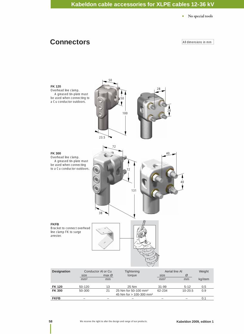
We reserve the right to alter the design and range of our products.58 Kabeldon 2009, edition 1
FK 120Overhead line clamp. A greased tin-plate must be used when connecting to a Cu conductor outdoors.
FK 300Overhead line clamp. A greased tin-plate must be used when connecting to a Cu conductor outdoors.
Connectors
Designation Conductor Al or Cu Tightening Aerial line Al Weight size max Ø torque size Ø mm² mm mm² mm kg/item FK 120 50-120 13 25 Nm 31-99 5-12 0.5FK 300 50-300 21 25 Nm for 50-100 mm² 62-234 10-20.5 0.9 45 Nm for > 100-300 mm²FKFB – – – – – 0.1
All dimensions in mm
• No special tools
FKFBBracket to connect overhead line clamp FK to surge arrester.
50
23.5
50
100
28
28
72
38
131
72
40
40
Kabeldon cable accessories 12-36 kVKabeldon cable accessories for XLPE cables 12-36 kV
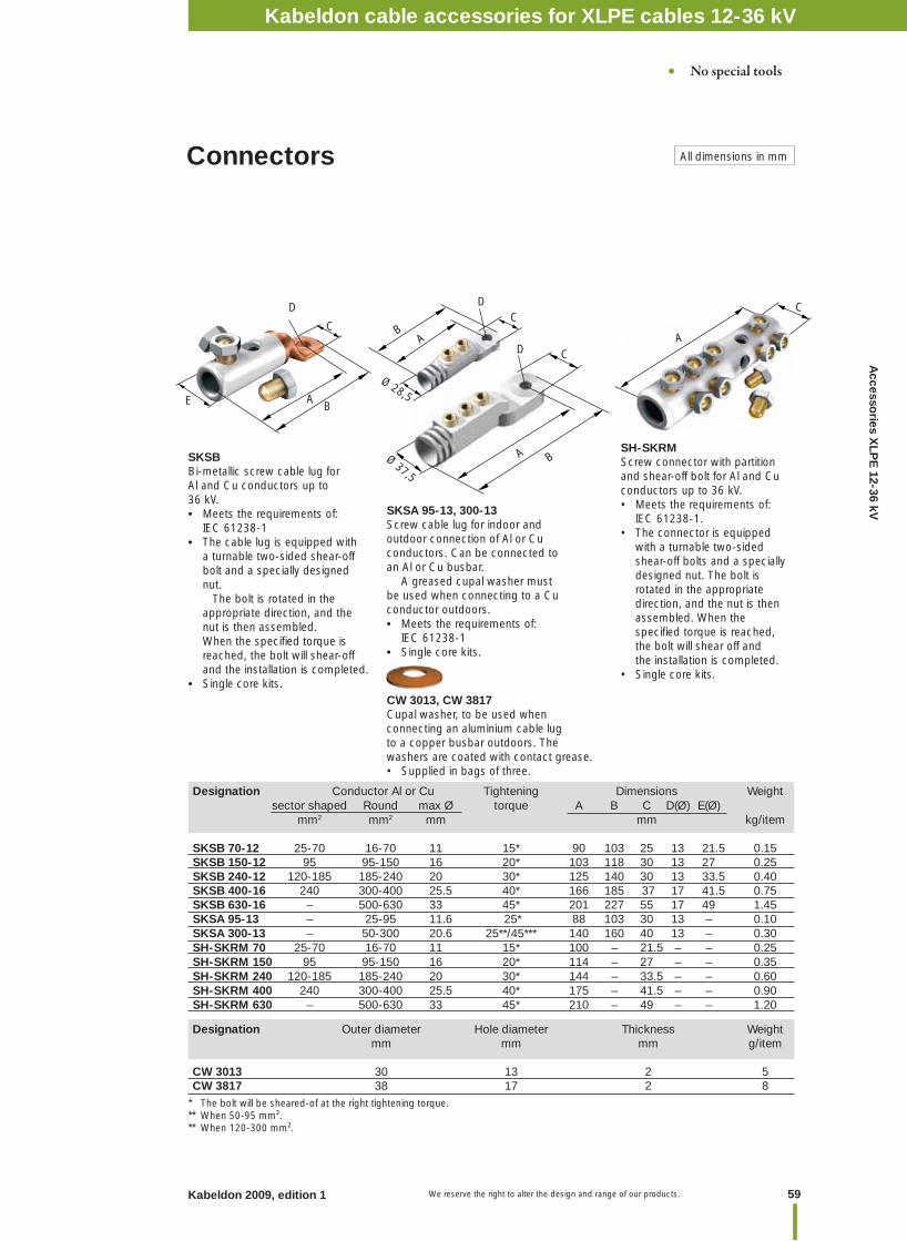
59Kabeldon 2009, edition 1 We reserve the right to alter the design and range of our products.
Accesso
ries XLP
E 12-36 kV
Designation Conductor Al or Cu Tightening Dimensions Weight sector shaped Round max Ø torque A B C D(Ø) E(Ø) mm2 mm2 mm mm kg/item SKSB 70-12 25-70 16-70 11 15* 90 103 25 13 21.5 0.15SKSB 150-12 95 95-150 16 20* 103 118 30 13 27 0.25SKSB 240-12 120-185 185-240 20 30* 125 140 30 13 33.5 0.40SKSB 400-16 240 300-400 25.5 40* 166 185 37 17 41.5 0.75SKSB 630-16 – 500-630 33 45* 201 227 55 17 49 1.45SKSA 95-13 – 25-95 11.6 25* 88 103 30 13 – 0.10SKSA 300-13 – 50-300 20.6 25**/45*** 140 160 40 13 – 0.30SH-SKRM 70 25-70 16-70 11 15* 100 – 21.5 – – 0.25SH-SKRM 150 95 95-150 16 20* 114 – 27 – – 0.35SH-SKRM 240 120-185 185-240 20 30* 144 – 33.5 – – 0.60SH-SKRM 400 240 300-400 25.5 40* 175 – 41.5 – – 0.90SH-SKRM 630 – 500-630 33 45* 210 – 49 – – 1.20
SKSA 95-13, 300-13Screw cable lug for indoor and outdoor connection of Al or Cu conductors. Can be connected to an Al or Cu busbar. A greased cupal washer must be used when connecting to a Cu conductor outdoors.• Meets the requirements of: IEC 61238-1• Single core kits.
Designation Outer diameter Hole diameter Thickness Weight mm mm mm g/item
CW 3013 30 13 2 5CW 3817 38 17 2 8
SH-SKRMScrew connector with partition and shear-off bolt for Al and Cu conductors up to 36 kV. • Meets the requirements of: IEC 61238-1.• The connector is equipped with a turnable two-sided shear-off bolts and a specially designed nut. The bolt is rotated in the appropriate direction, and the nut is then assembled. When the specifi ed torque is reached, the bolt will shear off and the installation is completed. • Single core kits.
CW 3013, CW 3817 Cupal washer, to be used when connecting an aluminium cable lug to a copper busbar outdoors. The washers are coated with contact grease. • Supplied in bags of three.
SKSB Bi-metallic screw cable lug for Al and Cu conductors up to 36 kV. • Meets the requirements of: IEC 61238-1• The cable lug is equipped with a turnable two-sided shear-off bolt and a specially designed nut. The bolt is rotated in the appropriate direction, and the nut is then assembled. When the specifi ed torque is reached, the bolt will shear-off and the installation is completed. • Single core kits.
Connectors All dimensions in mm
• No special tools
B
C
Ø 37,5
A
DA
C
Ø 28,5
C
AB
D
A
C
D
BE
* The bolt will be sheared-of at the right tightening torque.** When 50-95 mm².** When 120-300 mm².
Kabeldon cable accessories for XLPE cables 12-36 kV
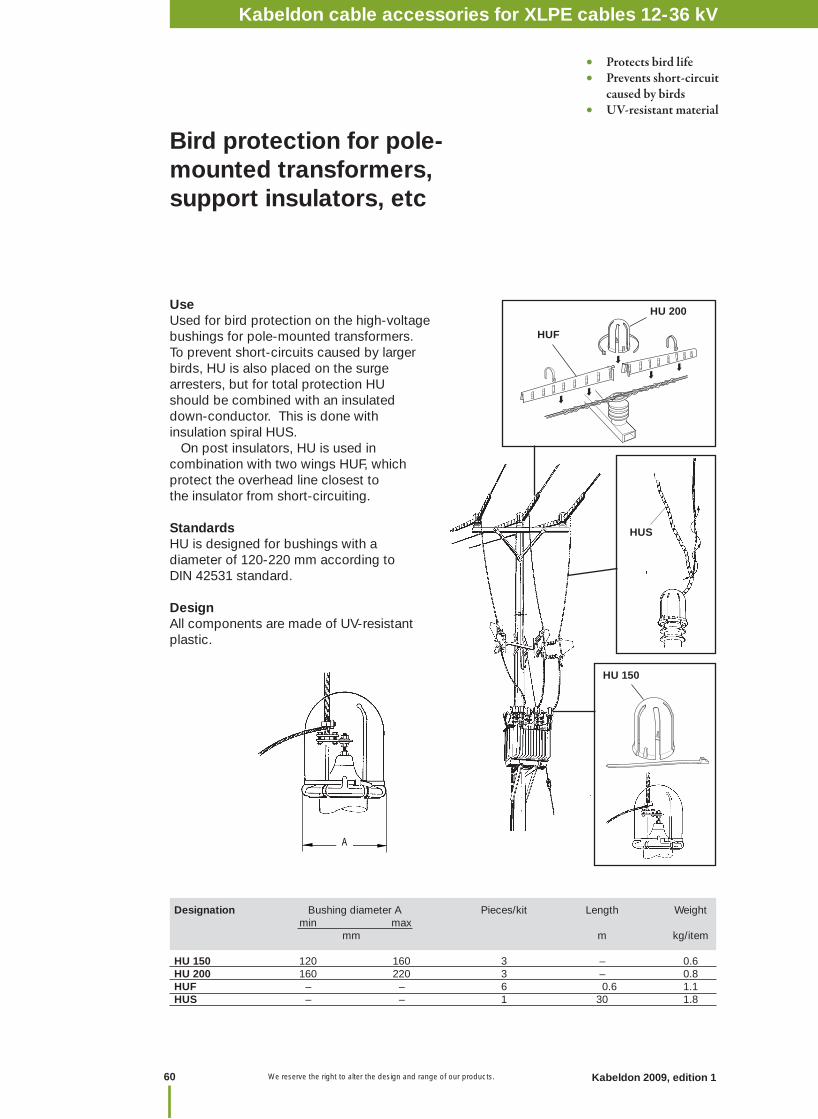
We reserve the right to alter the design and range of our products.60 Kabeldon 2009, edition 1
Bird protection for pole-mounted transformers, support insulators, etc
UseUsed for bird protection on the high-voltage bushings for pole-mounted transformers.To prevent short-circuits caused by larger birds, HU is also placed on the surge arresters, but for total protection HU should be combined with an insulated down-conductor. This is done with insulation spiral HUS. On post insulators, HU is used in combination with two wings HUF, which protect the overhead line closest to the insulator from short-circuiting.
StandardsHU is designed for bushings with a diameter of 120-220 mm according to DIN 42531 standard.
DesignAll components are made of UV-resistant plastic.
HU 150
HU 200
HUS
HUF
Designation Bushing diameter A Pieces/kit Length Weight min max mm m kg/item
HU 150 120 160 3 – 0.6 HU 200 160 220 3 – 0.8 HUF – – 6 0.6 1.1 HUS – – 1 30 1.8
• Protects bird life• Prevents short-circuit caused by birds• UV-resistant material
A
Kabeldon cable accessories for XLPE cables 12-36 kV
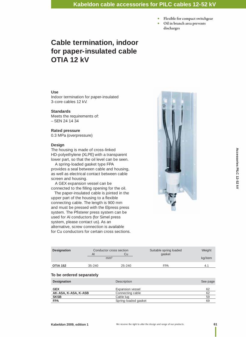
61Kabeldon 2009, edition 1 We reserve the right to alter the design and range of our products.
UseIndoor termination for paper-insulated3-core cables 12 kV.
StandardsMeets the requirements of:– SEN 24 14 34
Rated pressure0.3 MPa (overpressure)
DesignThe housing is made of cross-linked HD-polyethylene (XLPE) with a transparent lower part, so that the oil level can be seen. A spring-loaded gasket type FPA provides a seal between cable and housing, as well as electrical contact between cable screen and housing. A GEX expansion vessel can be connected to the fi lling opening for the oil. The paper-insulated cable is jointed in the upper part of the housing to a fl exible connecting cable. The length is 900 mm and must be pressed with the Elpress press system. The Pfi sterer press system can be used for Al conductors (for Simel press system, please contact us). As an alternative, screw connection is available for Cu conductors for certain cross sections.
Cable termination, indoor for paper-insulated cableOTIA 12 kV
Designation Description See page GEX Expansion vessel 62AK-ASA, K-ASA, K-ASB Connecting cable 62SKSB Cable lug 59FPA Spring-loaded gasket 69
To be ordered separately
Designation Conductor cross section Suitable spring loaded Weight Al Cu gasket mm² kg/item
OTIA 152 35-240 25-240 FPA 4.1
• Flexible for compact switchgear• Oil in branch area prevents discharges
Kabeldon cable accessories for PILC cables 12-52 kVA
ccessories P
ILC 12-52 kV
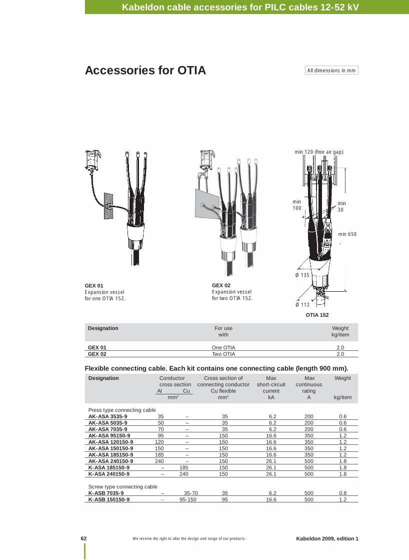
Kabeldon 2009, edition 1 We reserve the right to alter the design and range of our products.
GEX 01Expansion vessel for one OTIA 152.
Designation Conductor Cross section of Max Max Weight cross section connecting conductor short-circuit continuous Al Cu Cu fl exible current rating mm2 mm2 kA A kg/item
Press type connecting cableAK-ASA 3535-9 35 – 35 6.2 200 0.6 AK-ASA 5035-9 50 – 35 6.2 200 0.6 AK-ASA 7035-9 70 – 35 6.2 200 0.6 AK-ASA 95150-9 95 – 150 16.6 350 1.2 AK-ASA 120150-9 120 – 150 16.6 350 1.2 AK-ASA 150150-9 150 – 150 16.6 350 1.2 AK-ASA 185150-9 185 – 150 16.6 350 1.2 AK-ASA 240150-9 240 – 150 26.1 500 1.8 K-ASA 185150-9 – 185 150 26.1 500 1.8 K-ASA 240150-9 – 240 150 26.1 500 1.8 Screw type connecting cableK-ASB 7035-9 – 35-70 35 6.2 500 0.8 K-ASB 150150-9 – 95-150 95 16.6 500 1.2
Designation For use Weight with kg/item
GEX 01 One OTIA 2.0GEX 02 Two OTIA 2.0
GEX 02Expansion vessel for two OTIA 152.
Ø 112
min 30
Ø 135
min 120 (free air gap)
min 100
min 650
OTIA 152
Accessories for OTIA
Flexible connecting cable. Each kit contains one connecting cable (length 900 mm).
All dimensions in mm
62
Kabeldon cable accessories for PILC cables 12-52 kV
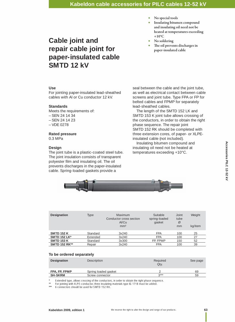
63Kabeldon 2009, edition 1 We reserve the right to alter the design and range of our products.
Designation Type Maximum Suitable Joint Weight Conductor cross section spring-loaded tube Al/Cu gasket Ø mm² mm kg/item SMTD 152 K Standard 3x240 FPA 100 25 SMTD 152 LK* Extended 3x240 FPA 100 27 SMTD 153 K Standard 3x300 FP, FPMP 150 52 SMTD 152 RK** Repair 3x240 FPA 100 39
Cable joint and repair cable joint for paper-insulated cable SMTD 12 kV
UseFor jointing paper-insulated lead-sheathed cables with Al or Cu conductor 12 kV.
StandardsMeets the requirements of:– SEN 24 14 34– SEN 24 14 23– VDE 0278
Rated pressure0.3 MPa
DesignThe joint tube is a plastic-coated steel tube. The joint insulation consists of transparent polyester fi lm and insulating oil. The oil prevents discharges in the paper-insulated cable. Spring-loaded gaskets provide a
To be ordered separately
* Extended type, allows crossing of the conductors, in order to obtain the right phase sequence.** For jointing with XLPE-conductor, three insulating materials type IG 1718 must be added.*** 6 connectors should be used for SMTD 152 RK.
seal between the cable and the joint tube, as well as electrical contact between cable screens and joint tube. Type FPA or FP for belted cables and FPMP for separately lead-sheathed cables. The length of the SMTD 152 LK and SMTD 153 K joint tube allows crossing of the conductors, in order to obtain the right phase sequence. The repair joint SMTD 152 RK should be completed with three extension cores, of paper- or XLPE-insulated cable (not included). Insulating bitumen compound and insulating oil need not be heated at temperatures exceeding +10°C.
• No special tools• Insulating bitumen compound and insulating oil need not be heated at temperatures exceeding +10°C• No soldering• Th e oil prevents discharges in paper-insulated cable
Designation Description Required See page Qty.
FPA, FP, FPMP Spring loaded gasket 2 69 SH-SKRM Screw connector 3*** 59
Kabeldon cable accessories for PILC cables 12-52 kVA
ccessories P
ILC 12-52 kV
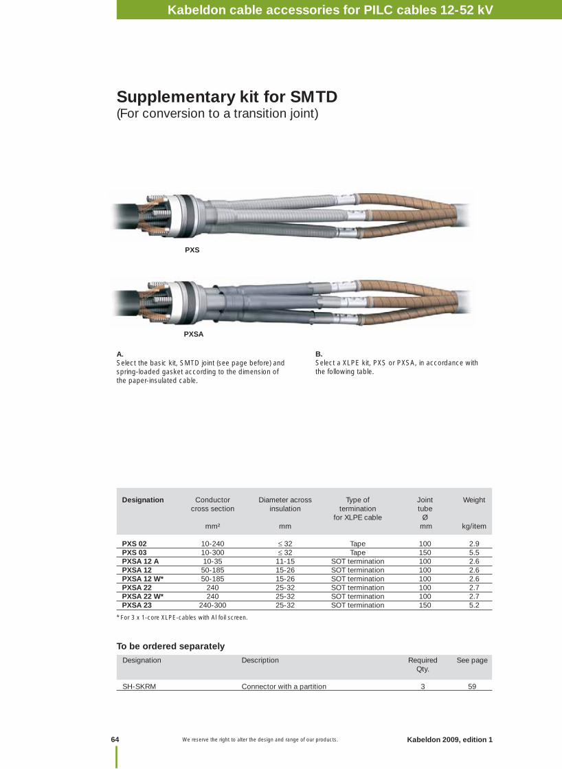
Kabeldon 2009, edition 1 We reserve the right to alter the design and range of our products.
Designation Description Required See page Qty.
SH-SKRM Connector with a partition 3 59
A. Select the basic kit, SMTD joint (see page before) and spring-loaded gasket according to the dimension of the paper-insulated cable.
To be ordered separately
Supplementary kit for SMTD(For conversion to a transition joint)
B. Select a XLPE kit, PXS or PXSA, in accordance with the following table.
Designation Conductor Diameter across Type of Joint Weight cross section insulation termination tube for XLPE cable Ø mm² mm mm kg/item
PXS 02 10-240 ≤ 32 Tape 100 2.9 PXS 03 10-300 ≤ 32 Tape 150 5.5 PXSA 12 A 10-35 11-15 SOT termination 100 2.6 PXSA 12 50-185 15-26 SOT termination 100 2.6 PXSA 12 W* 50-185 15-26 SOT termination 100 2.6PXSA 22 240 25-32 SOT termination 100 2.7 PXSA 22 W* 240 25-32 SOT termination 100 2.7PXSA 23 240-300 25-32 SOT termination 150 5.2
PXS
PXSA
* For 3 x 1-core XLPE-cables with Al foil screen.
64
Kabeldon cable accessories for PILC cables 12-52 kV
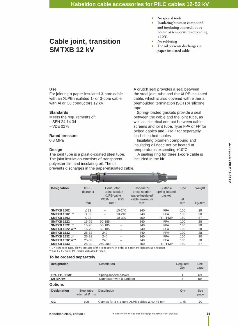
65Kabeldon 2009, edition 1 We reserve the right to alter the design and range of our products.
UseFor jointing a paper-insulated 3-core cable with an XLPE-insulated 1- or 3-core cablewith Al or Cu conductors 12 kV.
StandardsMeets the requirements of: – SEN 24 14 34– VDE 0278
Rated pressure0.3 MPa
DesignThe joint tube is a plastic-coated steel tube. The joint insulation consists of transparent polyester fi lm and insulating oil. The oil prevents discharges in the paper-insulated cable.
Designation XLPE- Conductor Conductor Suitable Tube Weight diameter cross section cross section spring-loaded XLPE-cable paper-insulated gasket PXSA PXS cable maximum Ø mm mm² mm² mm kg/item
SMTXB 1502 ≤ 32 – 10-240 240 FPA 100 28SMTXB 1502 L* ≤ 32 – 10-240 240 FPA 100 30SMTXB 1503 ≤ 32 – 10-300 300 FP, FPMP 150 57 SMTXB 1522 15-26 50-185 – 240 FPA 100 28 SMTXB 1522 L* 15-26 50-185 – 240 FPA 100 30 SMTXB 1522 W** 15-26 50-185 – 240 FPA 100 28 SMTXB 1532 25-32 240 – 240 FPA 100 28 SMTXB 1532 L* 25-32 240 – 240 FPA 100 30 SMTXB 1532 W** 25-32 240 – 240 FPA 100 28SMTXB 1533 25-32 240-300 – 300 FP, FPMP 150 57
Cable joint, transition SMTXB 12 kV
A crutch seal provides a seal between the steel joint tube and the XLPE-insulated cable, which is also covered with either a premoulded termination (SOT) or silicone tape. Spring-loaded gaskets provide a sealbetween the cable and the joint tube, as well as electrical contact between cable screens and joint tube. Type FPA or FP for belted cables and FPMP for separately lead-sheathed cables. Insulating bitumen compound and insulating oil need not be heated at temperatures exceeding +10°C. A sealing ring for three 1-core cable is included in the kit.
Designation Description Required See Qty. page
FPA, FP, FPMP Spring-loaded gasket 1 69SH-SKRM Connector with a partition 3 59
To be ordered separately
Options
• No special tools• Insulating bitumen compound and insulating oil need not be heated at temperatures exceeding +10°C• No soldering• Th e oil prevents discharges in paper-insulated cable
Designation Steel tube Description Qty. See internal Ø mm page
GC 100 Clamps for 3 x 1-core XLPE-cables Ø 40-45 mm 1 kit 70
* L = Extended type, allows crossing of the conductors, in order to obtain the right phase sequence.** For 3 x 1-core XLPE-cables with Al foil screen.
Kabeldon cable accessories for PILC cables 12-52 kVA
ccessories P
ILC 12-52 kV
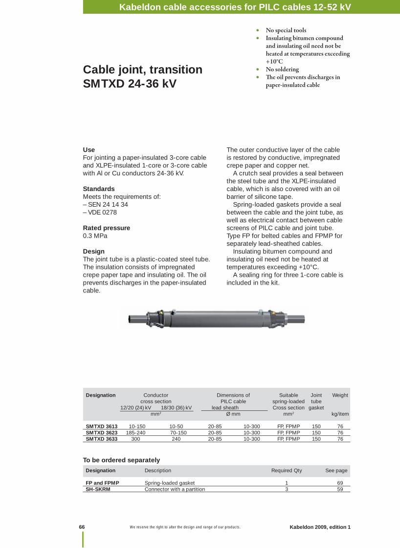
Kabeldon 2009, edition 1 We reserve the right to alter the design and range of our products.
Cable joint, transition SMTXD 24-36 kV
UseFor jointing a paper-insulated 3-core cable and XLPE-insulated 1-core or 3-core cable with Al or Cu conductors 24-36 kV.
StandardsMeets the requirements of:– SEN 24 14 34– VDE 0278
Rated pressure0.3 MPa
DesignThe joint tube is a plastic-coated steel tube. The insulation consists of impregnated crepe paper tape and insulating oil. The oil prevents discharges in the paper-insulated cable.
Designation Description Required Qty See page FP and FPMP Spring-loaded gasket 1 69SH-SKRM Connector with a partition 3 59
To be ordered separately
The outer conductive layer of the cable is restored by conductive, impregnated crepe paper and copper net. A crutch seal provides a seal between the steel tube and the XLPE-insulated cable, which is also covered with an oil barrier of silicone tape. Spring-loaded gaskets provide a sealbetween the cable and the joint tube, as well as electrical contact between cable screens of PILC cable and joint tube. Type FP for belted cables and FPMP for separately lead-sheathed cables. Insulating bitumen compound and insulating oil need not be heated at temperatures exceeding +10°C. A sealing ring for three 1-core cable is included in the kit.
Designation Conductor Dimensions of Suitable Joint Weight cross section PILC cable spring-loaded tube 12/20 (24) kV 18/30 (36) kV lead sheath Cross section gasket mm2 Ø mm mm2 kg/item SMTXD 3613 10-150 10-50 20-85 10-300 FP, FPMP 150 76 SMTXD 3623 185-240 70-150 20-85 10-300 FP, FPMP 150 76 SMTXD 3633 300 240 20-85 10-300 FP, FPMP 150 76
• No special tools• Insulating bitumen compound and insulating oil need not be heated at temperatures exceeding +10°C• No soldering• Th e oil prevents discharges in paper-insulated cable
66
Kabeldon cable accessories for PILC cables 12-52 kV

67Kabeldon 2009, edition 1 We reserve the right to alter the design and range of our products.
UseFor jointing paper-insulated 3-core cables with Al or Cu conductors 24-52 kV.
StandardsMeets the requirements of:– SEN 24 14 34– SEN 24 14 23
Rated pressure0.3 MPa
Cable joint for paper-insulated cable SMTA and SMTPA 24-52 kV
Designation Description Required See page Qty.
FP, FPA, FPMP Spring-loaded gasket 2 69SH-SKRM Screw connector 3 59
To be ordered separately
DesignThe joint tube is a plastic-coated steel tube. The insulation consists of impregnated crepe paper tape and insulating oil. The oil prevents discharges in the paper-insulated cable. The outer conductive layer of the cable is restored by conductive, impregnated crepe paper and copper net. Spring-loaded gaskets provide a sealbetween the cable and the joint tube, as well as electrical contact between cable screens and joint tube. Type FPA or FP for belted cables and FPMP for separately lead-sheathed cables. Insulating bitumen compound and insulating oil need not be heated at temperatures exceeding +10°C.
Designation Maximum conductor Diameter of Suitable Joint Weight cross section Al/Cu lead sheathed spring-loaded tube 24 kV 36 kV 52 kV min max gasket mm² mm kg/item
For belted cableSMTA 24362 3x120 3x70 – 12 63 FPA 100 25
For belted and separate lead-sheathed cableSMTPA 24523 3x300 3x240 3x150 20 85 FP/FPMP 150 62
• No special tools• Insulating bitumen compound and insulating oil need not be heated at temperatures exceeding +10°C• No soldering• Th e oil prevents discharges in paper-insulated cable
Kabeldon cable accessories for PILC cables 12-52 kVA
ccessories P
ILC 12-52 kV
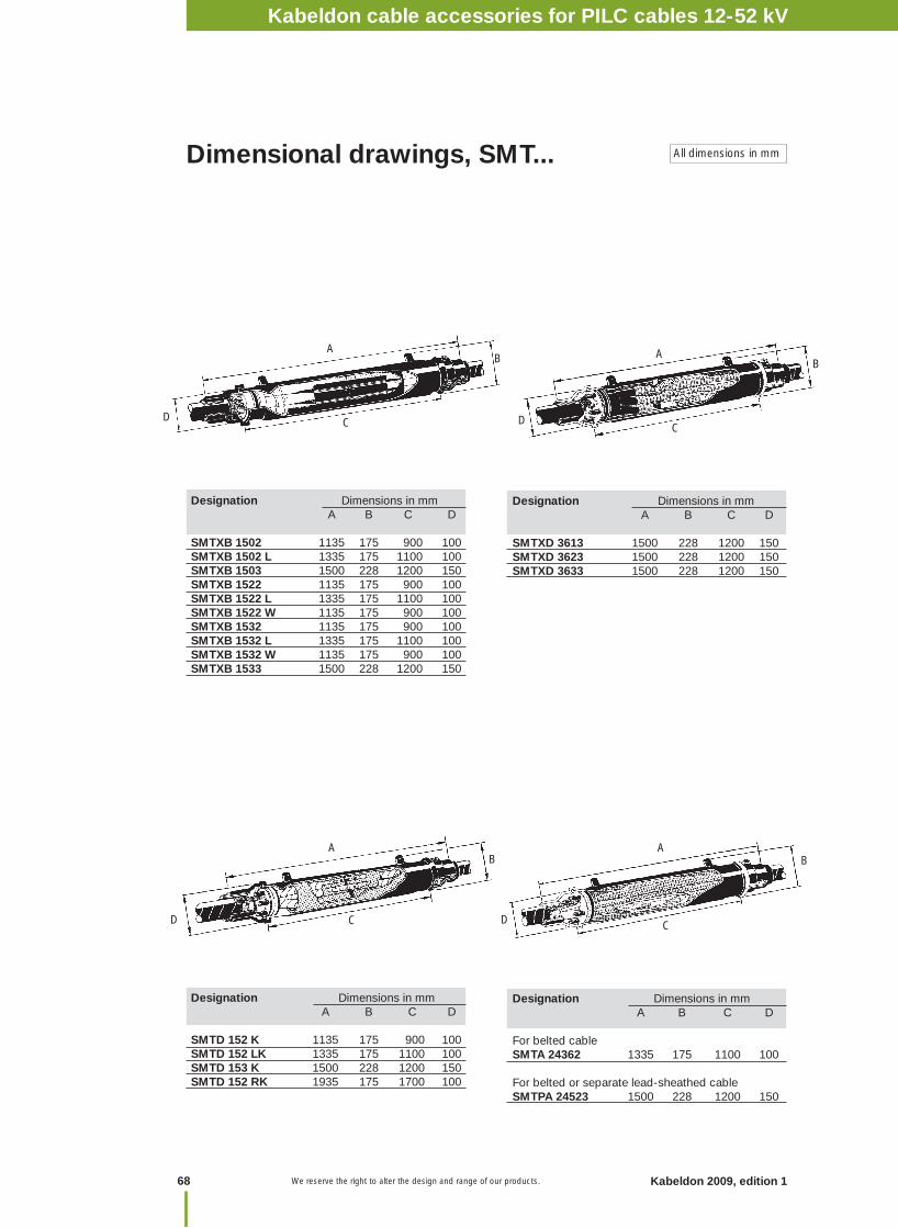
Kabeldon 2009, edition 1 We reserve the right to alter the design and range of our products.
Dimensional drawings, SMT...
Designation Dimensions in mm A B C D SMTXB 1502 1135 175 900 100 SMTXB 1502 L 1335 175 1100 100 SMTXB 1503 1500 228 1200 150 SMTXB 1522 1135 175 900 100 SMTXB 1522 L 1335 175 1100 100 SMTXB 1522 W 1135 175 900 100 SMTXB 1532 1135 175 900 100 SMTXB 1532 L 1335 175 1100 100 SMTXB 1532 W 1135 175 900 100 SMTXB 1533 1500 228 1200 150
AB
CD
Designation Dimensions in mm A B C D
SMTXD 3613 1500 228 1200 150 SMTXD 3623 1500 228 1200 150 SMTXD 3633 1500 228 1200 150
A
CD
B
AB
CD
Designation Dimensions in mm A B C D
SMTD 152 K 1135 175 900 100 SMTD 152 LK 1335 175 1100 100 SMTD 153 K 1500 228 1200 150SMTD 152 RK 1935 175 1700 100
Designation Dimensions in mm A B C D
For belted cableSMTA 24362 1335 175 1100 100
For belted or separate lead-sheathed cable SMTPA 24523 1500 228 1200 150
AB
D C
All dimensions in mm
68
Kabeldon cable accessories for PILC cables 12-52 kV
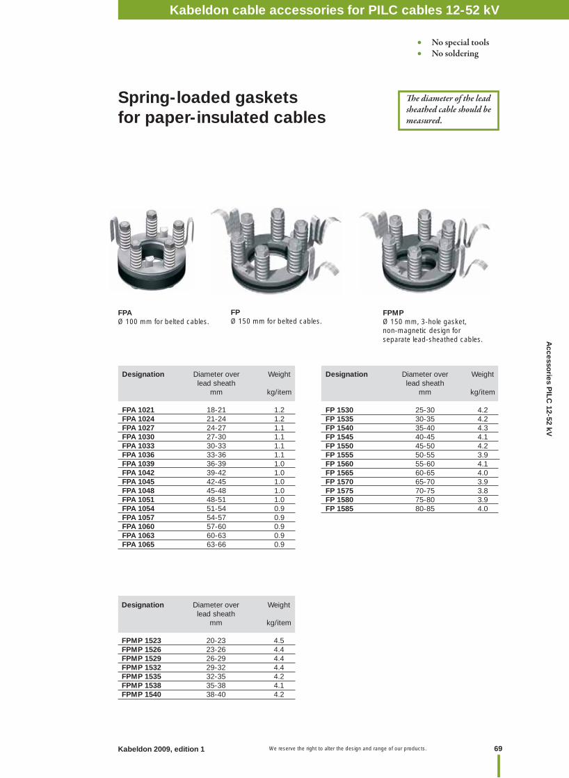
69Kabeldon 2009, edition 1 We reserve the right to alter the design and range of our products.
Spring-loaded gasketsfor paper-insulated cables
FPMPØ 150 mm, 3-hole gasket,non-magnetic design for separate lead-sheathed cables.
FPØ 150 mm for belted cables.
FPAØ 100 mm for belted cables.
Designation Diameter over Weight lead sheath mm kg/item
FPA 1021 18-21 1.2FPA 1024 21-24 1.2FPA 1027 24-27 1.1FPA 1030 27-30 1.1FPA 1033 30-33 1.1FPA 1036 33-36 1.1FPA 1039 36-39 1.0FPA 1042 39-42 1.0FPA 1045 42-45 1.0FPA 1048 45-48 1.0FPA 1051 48-51 1.0FPA 1054 51-54 0.9FPA 1057 54-57 0.9FPA 1060 57-60 0.9FPA 1063 60-63 0.9FPA 1065 63-66 0.9
Designation Diameter over Weight lead sheath mm kg/item FP 1530 25-30 4.2FP 1535 30-35 4.2FP 1540 35-40 4.3FP 1545 40-45 4.1FP 1550 45-50 4.2FP 1555 50-55 3.9FP 1560 55-60 4.1FP 1565 60-65 4.0FP 1570 65-70 3.9FP 1575 70-75 3.8FP 1580 75-80 3.9FP 1585 80-85 4.0
Designation Diameter over Weight lead sheath mm kg/item
FPMP 1523 20-23 4.5FPMP 1526 23-26 4.4FPMP 1529 26-29 4.4FPMP 1532 29-32 4.4FPMP 1535 32-35 4.2FPMP 1538 35-38 4.1FPMP 1540 38-40 4.2
Th e diameter of the lead sheathed cable should be measured.
No special tools No soldering
Kabeldon cable accessories for PILC cables 12-52 kVA
ccessories P
ILC 12-52 kV

Kabeldon 2009, edition 1 We reserve the right to alter the design and range of our products.
General accessories for paper-insulated cable joints and transition joints
RKM 402Funnel for oil fi lling.
Designation Use Length Width Thickness Weight m mm mm kg/item
GC SMTXB with Ø 100 joint tube Cable Ø 40-45 – – 0.72IA 1003 Paper-insulated cable joint – – – 0.13IA 2112 Paper-insulated cable joint 9 10 – 0.40 IA 2113 Paper-insulated cable joint 9 24 – 0.60IA 2502 For fi lling cable clamps 3 83 0.5 0.20 IA 2508 For fi lling cable clamps 14 200 0.5 1.40IA 2518 For fi lling cable clamps 10 83 0.5 0.50IA 2519 For fi lling cable clamps 14 100 0.5 0.75IKP – – – – 0.30RKM 402 For oil fi lling – – – 0.10
IA 2502 - 2519Bituminized paper for fi lling, for example in cable clamps.
IA 2112 - 2113Impregnated crepe paper tape.
IA 1003Stress controlling tape.
IKPImpregnated carbon crepe paper (conductive).
GCThe kit contains one sealing ring, screws and two roomy clamp halves for Ø 100 mm joint tubes. The clamps are made from glass fi bre reinforced polymer. The bolt and washer are moulded into the material. Used on the XLPE side of the transition joints; SMTXB 1502/1522/1532 when installing 1-core cables with an outer diameter greater than 40 mm.
70
Kabeldon cable accessories for PILC cables 12-52 kV
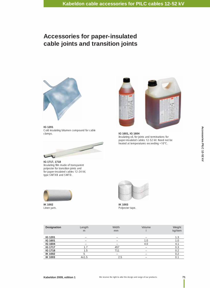
71Kabeldon 2009, edition 1 We reserve the right to alter the design and range of our products.
Designation Length Width Volume Weight m mm l kg/item
IG 1201 – – – 1.3IG 1601 – – 1.0 1.0IG 1604 – – 4.0 4.1IG 1717 1.7 457 – 0.3IG 1718 1.5 711 – 0.2IK 1002 5 – – 0.2IK 1003 4x1.5 2.5 – 0.1
IG 1601, IG 1604Insulating oil, for joints and terminations for paper-insulated cables 12-52 kV. Need not be heated at temperatures exceeding +10°C.
IG 1717, 1718Insulating fi lm made of transparent polyester for transition joints and for paper-insulated cables 12-24 kV, type SMTXB and SMTD.
IG 1201Cold insulating bitumen compound for cable clamps.
IK 1002Linen yarn.
IK 1003Polyester tape.
Accessories for paper-insulated cable joints and transition joints
Kabeldon cable accessories for PILC cables 12-52 kVA
ccessories P
ILC 12-52 kV
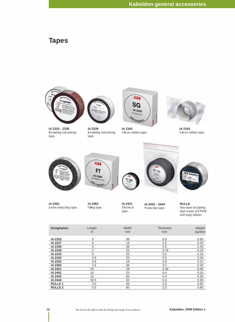
Tapes
IA 2333 - 2338Insulating vulcanizing tape.
IA 2342Silicon rubber tape.
IA 2339Insulating vulcanizing tape.
IA 2343Silicon rubber tape.
Designation Length Width Thickness Weight m mm mm kg/item IA 2333 9 38 0.8 0.50IA 2337 9 19 0.5 0.20IA 2338 9 38 0.5 0.40IA 2339 2 25 0.76 0.10IA 2342 9 25 0.5 0.16IA 2343 2.5 25 0.5 0.30IA 2352 4.5 19 0.8 0.10IA 2362 1.5 38 3.2 0.30IA 2421 10 19 0.18 0.06IA 2441 10 25 0.4 0.20IA 2443 10 50 0.4 0.30IA 2444 30.5 50 0.4 0.90RULLE 1 3.5 60 2.0 0.60RULLE 2 5.5 60 2.0 0.90
IA 2441 - 2444Protective tape.
IA 2421Electrical tape.
IA 2352Semiconducting tape.
IA 2362Filling tape.
RULLETwo-layer insulating tape made of EPDM and butyl rubber.
Kabeldon cable accessories 1 kVNotes
72 Kabeldon, 2009 Edition 1 We reserve the right to alter the design and range of our products.
Kabeldon general accessories

73Kabeldon 2009, edition 1 We reserve the right to alter the design and range of our products.
Designation Length Diameter Coarseness Weight m mm kg/item
IK 1105 1 – 100 0.1IK 1106 1 – 80 0.1IK 1107 1 – 120 0.1IK 1108 1 – 220 0.1IK 1109 1 – 400 0.1IK 1401 2 1.4 – 0.1IK 1405 5 1.4 – 0.1IK 1406 9.5 1.4 – 0.2IK 1407 6 1.0 – 0.2IK 1502 4 1.5 – 0.1IK 2221 – – – 0.03IK 2233 – – – 0.02
IK 2221Silicone grease, 25 g.
IK 2233Grease, type AP paste, 10 g.
IK 1405, IK 1406Lashing wire (tin-coated copper wire).
IK 1502Lashing wire (galvanized steel wire).
IK 1401, IK 1407Lashing wire (tin-coated copper wire).
IK 1105, 1106, 1107, 1108, 1109Abrasive cloth.
Other accessories
Kabeldon general accessories
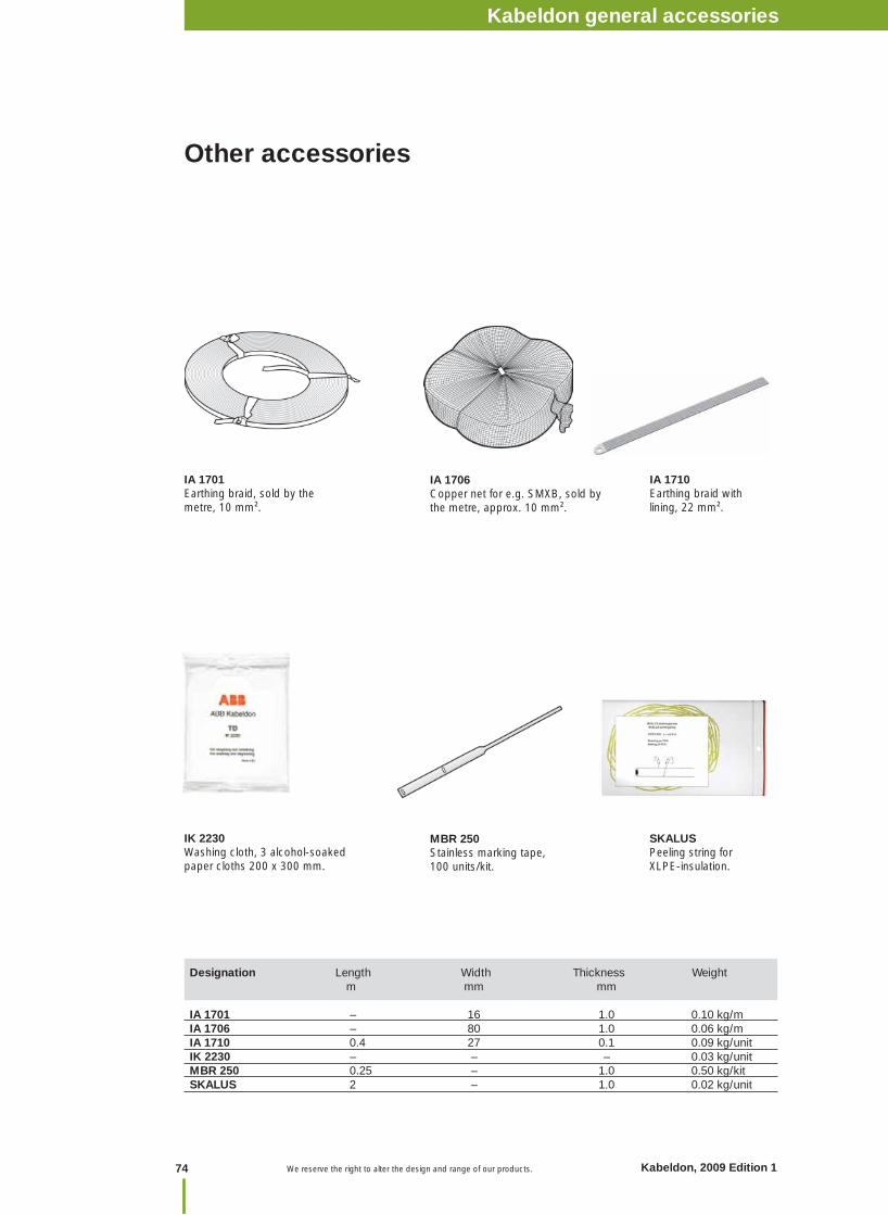
Designation Length Width Thickness Weight m mm mm
IA 1701 – 16 1.0 0.10 kg/m IA 1706 – 80 1.0 0.06 kg/m IA 1710 0.4 27 0.1 0.09 kg/unitIK 2230 – – – 0.03 kg/unitMBR 250 0.25 – 1.0 0.50 kg/kitSKALUS 2 – 1.0 0.02 kg/unit
MBR 250Stainless marking tape, 100 units/kit.
IA 1706Copper net for e.g. SMXB, sold by the metre, approx. 10 mm².
IA 1701Earthing braid, sold by the metre, 10 mm².
IA 1710Earthing braid with lining, 22 mm².
SKALUSPeeling string forXLPE-insulation.
IK 2230Washing cloth, 3 alcohol-soakedpaper cloths 200 x 300 mm.
Other accessories
Kabeldon cable accessories 1 kVNotes
74 Kabeldon, 2009 Edition 1 We reserve the right to alter the design and range of our products.
Kabeldon general accessories
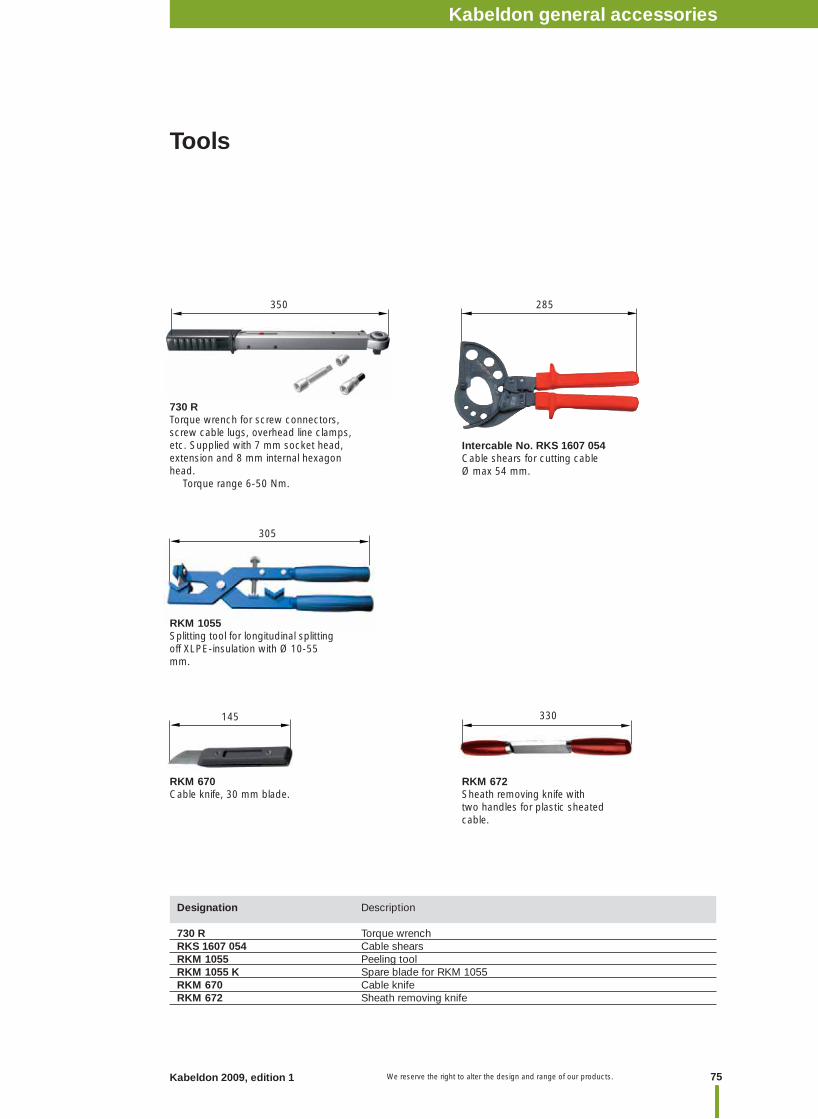
75Kabeldon 2009, edition 1 We reserve the right to alter the design and range of our products.
Tools
Designation Description 730 R Torque wrench RKS 1607 054 Cable shears RKM 1055 Peeling toolRKM 1055 K Spare blade for RKM 1055RKM 670 Cable knife RKM 672 Sheath removing knife
Intercable No. RKS 1607 054Cable shears for cutting cable Ø max 54 mm.
RKM 670Cable knife, 30 mm blade.
RKM 672Sheath removing knife with two handles for plastic sheated cable.
145 330
305
285350
730 RTorque wrench for screw connectors, screw cable lugs, overhead line clamps, etc. Supplied with 7 mm socket head, extension and 8 mm internal hexagon head. Torque range 6-50 Nm.
RKM 1055Splitting tool for longitudinal splitting off XLPE-insulation with Ø 10-55 mm.
Kabeldon general accessories
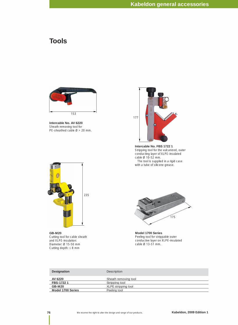
Designation Description AV 6220 Sheath removing tool FBS-1722 1 Stripping tool GB-M20 XLPE stripping tool Model 1700 Series Peeling tool
GB-M20Cutting tool for cable sheath and XLPE-insulation: Diameter: Ø 15-50 mmCutting depth: 8 mm
Intercable No. FBS 1722 1Stripping tool for the vulcanized, outer conducting layer of XLPE-insulated cable Ø 10-52 mm. The tool is supplied in a rigid case with a tube of silicone grease.
Intercable No. AV 6220Sheath removing tool for PE-sheathed cable Ø > 20 mm.
Model 1700 SeriesPeeling tool for strippable outer conductive layer on XLPE-insulated cable Ø 13-51 mm.
Tools
177153
235
175
Kabeldon cable accessories 1 kVNotes
76 Kabeldon, 2009 Edition 1 We reserve the right to alter the design and range of our products.
Kabeldon general accessories
77Kabeldon 2009, edition 1 We reserve the right to alter the design and range of our products. We reserve the right to alter the design and range of our products.
Kabeldon cable accessories 1 kVNotesKabeldon cable accessories 52-420 kV
Table of contentsCable accessories 52-420 kV
Page No.
Introduction cable accessories 52-420 kV ............................................................................ 78
Cable terminations, outdoor, porcelain APED 36-84/composite APED P 36 & 72 kV ......... 79
Cable terminations, outdoor porcelain APECB 84-420/composite APECB P 84-300 kV .... 82
Cable terminations, outdoor fl exible APSEA 52-72 kV ...................................................... 85
Cable terminations, APEGA GIS/TRF 84-420 kV .................................................................. 88
Cable joints, premoulded JS 52-123 kV, JX 52-123 kV ....................................................... 92
Cable joints, premoulded JS 245 kV, JX 245 kV .................................................................. 96
Cable joints, premoulded SMPGB, SMPGB-C, SMPGB BOX 145-170 kV ......................... 98
Cable joints, premoulded SMPGB 362-420 kV .................................................................. 101
Earth kits for cable terminations .......................................................................................... 103
Tools and oil ........................................................................................................................ 105
Cab
le accessories 52-420 kV
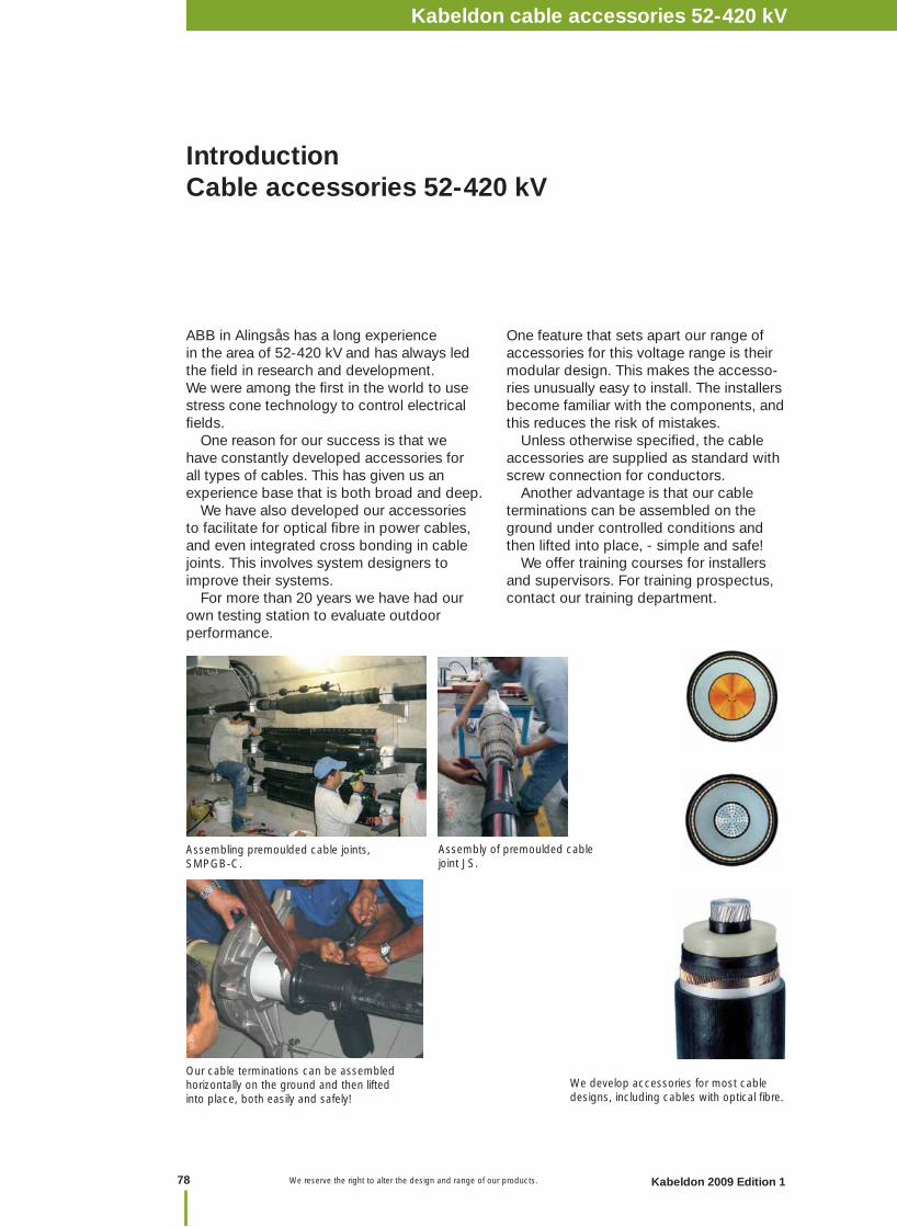
We reserve the right to alter the design and range of our products.
Introduction Cable accessories 52-420 kV
We develop accessories for most cable designs, including cables with optical fi bre.
ABB in Alingsås has a long experience in the area of 52-420 kV and has always led the fi eld in research and development. We were among the fi rst in the world to use stress cone technology to control electrical fi elds. One reason for our success is that we have constantly developed accessories for all types of cables. This has given us an experience base that is both broad and deep. We have also developed our accessories to facilitate for optical fi bre in power cables, and even integrated cross bonding in cable joints. This involves system designers to improve their systems. For more than 20 years we have had our own testing station to evaluate outdoor performance.
Assembling premoulded cable joints, SMPGB-C.
Our cable terminations can be assembled horizontally on the ground and then lifted into place, both easily and safely!
One feature that sets apart our range of accessories for this voltage range is their modular design. This makes the accesso-ries unusually easy to install. The installers become familiar with the components, and this reduces the risk of mistakes. Unless otherwise specifi ed, the cable accessories are supplied as standard with screw connection for conductors. Another advantage is that our cable terminations can be assembled on the ground under controlled conditions and then lifted into place, - simple and safe! We offer training courses for installers and supervisors. For training prospectus, contact our training department.
Assembly of premoulded cable joint JS.
Kabeldon cable accessories 1 kVNotes
78 Kabeldon 2009 Edition 1
Kabeldon cable accessories 52-420 kV
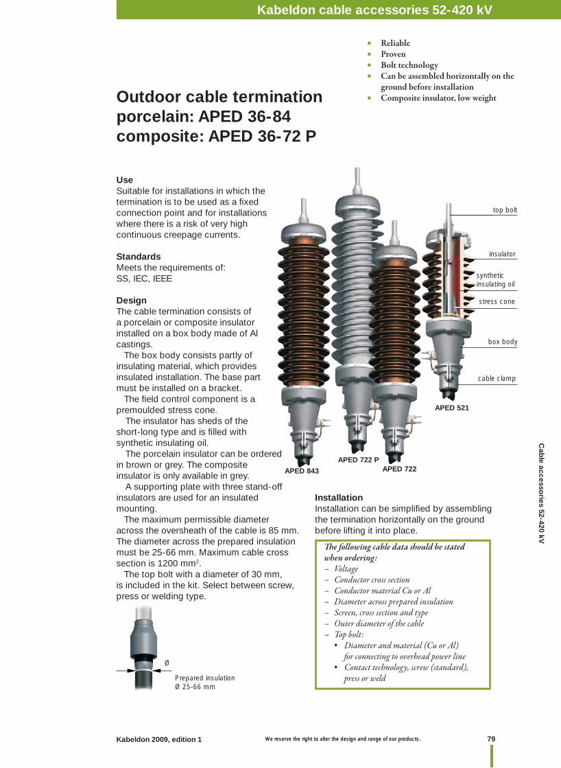
79Kabeldon 2009, edition 1 We reserve the right to alter the design and range of our products. We reserve the right to alter the design and range of our products.
Kabeldon cable accessories 1 kVNotesKabeldon cable accessories 52-420 kV
Outdoor cable termination porcelain: APED 36-84 composite: APED 36-72 P
Prepared insulationØ 25-66 mm
Th e following cable data should be stated when ordering:– Voltage– Conductor cross section– Conductor material Cu or Al– Diameter across prepared insulation– Screen, cross section and type– Outer diameter of the cable – Top bolt: • Diameter and material (Cu or Al) for connecting to overhead power line • Contact technology, screw (standard), press or weld
Ø
• Reliable• Proven• Bolt technology• Can be assembled horizontally on the ground before installation • Composite insulator, low weight
APED 843
APED 521
APED 722APED 722 P
top bolt
synthetic insulating oil
stress cone
box body
cable clamp
insulator
UseSuitable for installations in which the termination is to be used as a fi xed connection point and for installations where there is a risk of very high continuous creepage currents.
StandardsMeets the requirements of: SS, IEC, IEEE
DesignThe cable termination consists of a porcelain or composite insulator installed on a box body made of Al castings. The box body consists partly of insulating material, which provides insulated installation. The base part must be installed on a bracket. The fi eld control component is a premoulded stress cone. The insulator has sheds of the short-long type and is fi lled with synthetic insulating oil. The porcelain insulator can be ordered in brown or grey. The composite insulator is only available in grey. A supporting plate with three stand-off insulators are used for an insulated mounting. The maximum permissible diameter across the oversheath of the cable is 85 mm. The diameter across the prepared insulation must be 25-66 mm. Maximum cable cross section is 1200 mm2. The top bolt with a diameter of 30 mm, is included in the kit. Select between screw, press or welding type.
InstallationInstallation can be simplifi ed by assembling the termination horizontally on the ground before lifting it into place.
Cab
le accessories 52-420 kV
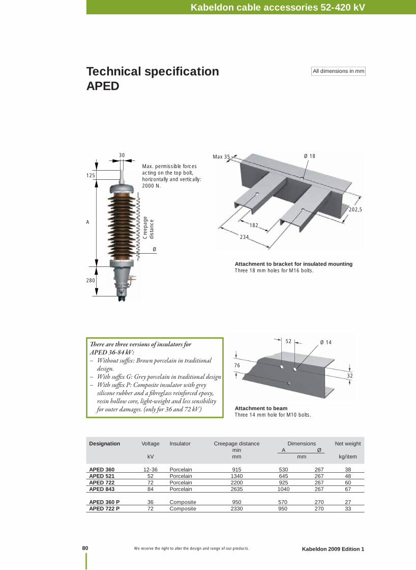
We reserve the right to alter the design and range of our products.
Designation Voltage Insulator Creepage distance Dimensions Net weight min A Ø kV mm mm kg/item APED 360 12-36 Porcelain 915 530 267 38APED 521 52 Porcelain 1340 645 267 48APED 722 72 Porcelain 2200 925 267 60APED 843 84 Porcelain 2635 1040 267 67
APED 360 P 36 Composite 950 570 270 27APED 722 P 72 Composite 2330 950 270 33
Technical specifi cationAPED
All dimensions in mm
Cre
epag
e di
stan
ce
280
125
A
30
Ø
32
76
52 Ø 14
Attachment to beamThree 14 mm hole for M10 bolts.
Attachment to bracket for insulated mountingThree 18 mm holes for M16 bolts.
Max. permissible forces acting on the top bolt, horizontally and vertically: 2000 N.
Th ere are three versions of insulators for APED 36-84 kV:– Without suffi x: Brown porcelain in traditional design.– With suffi x G: Grey porcelain in traditional design– With suffi x P: Composite insulator with grey silicone rubber and a fi breglass reinforced epoxy, resin hollow core, light-weight and less sensibility for outer damages. (only for 36 and 72 kV)
202,5
182
234
Max 35 Ø 18
Kabeldon cable accessories 1 kVNotes
80 Kabeldon 2009 Edition 1
Kabeldon cable accessories 52-420 kV
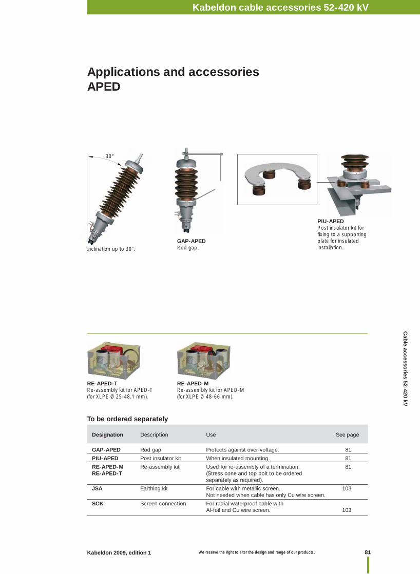
81Kabeldon 2009, edition 1 We reserve the right to alter the design and range of our products. We reserve the right to alter the design and range of our products.
Kabeldon cable accessories 1 kVNotesKabeldon cable accessories 52-420 kV
PIU-APEDPost insulator kit for fi xing to a supporting plate for insulated installation.
Applications and accessoriesAPED
GAP-APEDRod gap.
To be ordered separately
RE-APED-M Re-assembly kit for APED-M(for XLPE Ø 48-66 mm).
30°
Designation Description Use See page
GAP-APED Rod gap Protects against over-voltage. 81
PIU-APED Post insulator kit When insulated mounting. 81
RE-APED-M Re-assembly kit Used for re-assembly of a termination. 81RE-APED-T (Stress cone and top bolt to be ordered separately as required).
JSA Earthing kit For cable with metallic screen. 103 Not needed when cable has only Cu wire screen.
SCK Screen connection For radial waterproof cable with Al-foil and Cu wire screen. 103
RE-APED-TRe-assembly kit for APED-T(for XLPE Ø 25-48.1 mm).
Inclination up to 30°.
Cab
le accessories 52-420 kV

We reserve the right to alter the design and range of our products.
APECB 245-300 P
APECB 84
APECB 170
APECB 420
top bolt
stress cone
cable clamp
insulator
base part
synthetic insulating oil
When ordering, please state the following data:– Voltage– Conductor cross section, diameter– Diameter across prepared insulation– Screen, cross section and type (optical fi bres)– Outer diameter of cable– Insulator, porcelain or composite– Top bolt: • Diameter and material (Cu or Al) for connecting to overhead power line
Prepared insulation
Voltage XLPE-diameter Outer Ø mm sheath kV min max Ø mm
170 45.5 107 170 245 45.5 120 170 300 80 120 170 420 80 120 170
ØØ
APECB 245APECB 300APECB 420
APECB 84 APECB 145 APECB 170
Outdoor cable termination porcelain: APECB 84-420 composite: APECB 84-300 P
• Reliable• Proven• Bolt technology• Can be assembled horizontally on the ground before installation • Will fi t large cables• Low total weight• Integrated insulated installation• Few components
InstallationInstallation can be simplifi ed by assembling the termination horizontally on the ground before lifting it into place.
APECB 145 P
APECB 245-300
APECB 84 P
UseFor installations in which the termination is to be used as a fi xed connection point and in installations where there is a risk of very high continuous creepage currents.
StandardMeets the requirements of: SS, IEC, IEEE
DesignThe cable termination consists of a porcelain or composite insulator installed on a box body made of Al castings. The box body consists partly of insulating material, which provides insulated installation. The base part must be installed on a bracket. For 420 kV post-insulator kit must be used. The fi eld control component is a premoulded stress cone. The insulator has sheds of short-long type and is fi lled with synthetic insulating oil. The porcelain insulator can be ordered in brown or grey. The composite insulator is only available in grey for 84-300 kV. For the maximum permitted diameter across the oversheath of the cable and the diameter across prepared insulation, see the table below. A screw clamp in the top fi tting is used to connect the conductor to the top bolt. Top bolt and screw clamp are included in the kit.
Kabeldon cable accessories 1 kVNotes
82 Kabeldon 2009 Edition 1
Kabeldon cable accessories 52-420 kV
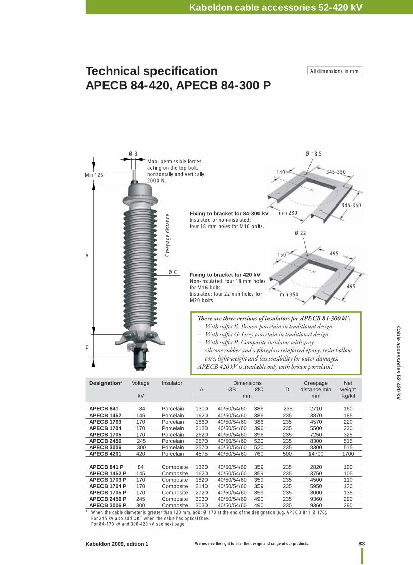
83Kabeldon 2009, edition 1 We reserve the right to alter the design and range of our products. We reserve the right to alter the design and range of our products.
Kabeldon cable accessories 1 kVNotesKabeldon cable accessories 52-420 kV
Designation* Voltage Insulator Dimensions Creepage Net A ØB ØC D distance min weight kV mm mm kg/kit APECB 841 84 Porcelain 1300 40/50/54/60 386 235 2710 160 APECB 1452 145 Porcelain 1620 40/50/54/60 386 235 3870 185APECB 1703 170 Porcelain 1860 40/50/54/60 386 235 4570 220 APECB 1704 170 Porcelain 2120 40/50/54/60 396 235 5500 230APECB 1705 170 Porcelain 2620 40/50/54/60 396 235 7250 325APECB 2456 245 Porcelain 2570 40/50/54/60 520 235 8300 515APECB 3006 300 Porcelain 2570 40/50/54/60 520 235 8300 515APECB 4201 420 Porcelain 4575 40/50/54/60 760 500 14700 1700
APECB 841 P 84 Composite 1320 40/50/54/60 359 235 2820 100APECB 1452 P 145 Composite 1620 40/50/54/60 359 235 3750 105 APECB 1703 P 170 Composite 1820 40/50/54/60 359 235 4500 110APECB 1704 P 170 Composite 2140 40/50/54/60 359 235 5950 120APECB 1705 P 170 Composite 2720 40/50/54/60 359 235 8000 135APECB 2456 P 245 Composite 3030 40/50/54/60 490 235 9360 290APECB 3006 P 300 Composite 3030 40/50/54/60 490 235 9360 290
Technical specifi cationAPECB 84-420, APECB 84-300 P
All dimensions in mm
* When the cable diameter is greater than 120 mm, add: Ø 170 at the end of the designation (e.g. APECB 841 Ø 170). For 245 kV also add OKT when the cable has optical fi bre. For 84-170 kV and 300-420 kV see next page!
Th ere are three versions of insulators for APECB 84-300 kV:– With suffi x B: Brown porcelain in traditional design.– With suffi x G: Grey porcelain in traditional design– With suffi x P: Composite insulator with grey silicone rubber and a fi breglass reinforced epoxy, resin hollow core, light-weight and less sensibility for outer damages.APECB 420 kV is available only with brown porcelain!
D
A
Ø B
Min 125
Cre
epag
e di
stan
ce
Ø C Fixing to bracket for 420 kVNon-insulated: four 18 mm holes for M16 bolts. Insulated: four 22 mm holes for M20 bolts.
495
Ø 22
min 350
495150
345-350
Ø 18,5
min 280
345-350140
Fixing to bracket for 84-300 kVInsulated or non-insulated: four 18 mm holes for M16 bolts.
Max. permissible forces acting on the top bolt, horizontally and vertically: 2000 N.
Cab
le accessories 52-420 kV
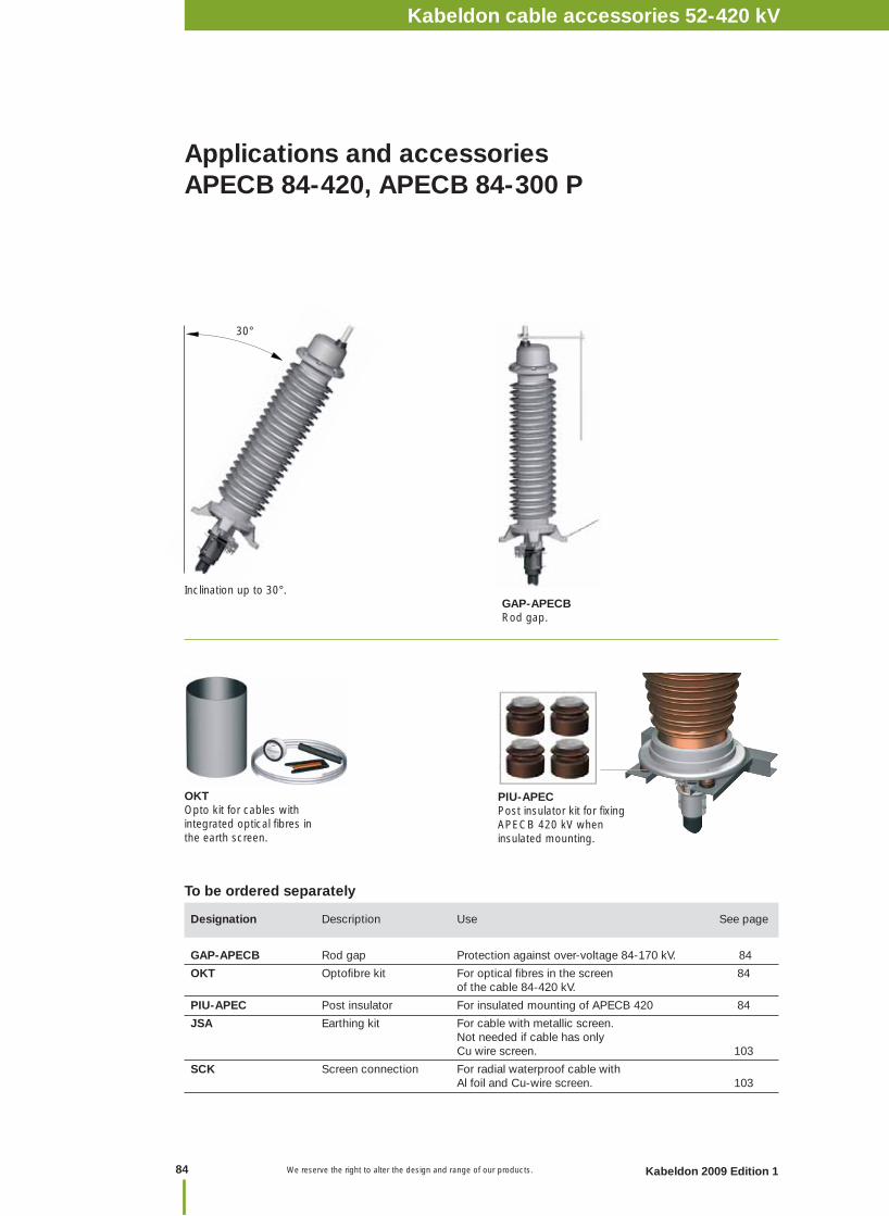
We reserve the right to alter the design and range of our products.
Applications and accessoriesAPECB 84-420, APECB 84-300 P
Designation Description Use See page
GAP-APECB Rod gap Protection against over-voltage 84-170 kV. 84
OKT Optofi bre kit For optical fi bres in the screen 84 of the cable 84-420 kV.
PIU-APEC Post insulator For insulated mounting of APECB 420 84
JSA Earthing kit For cable with metallic screen. Not needed if cable has only Cu wire screen. 103
SCK Screen connection For radial waterproof cable with Al foil and Cu-wire screen. 103
GAP-APECBRod gap.
To be ordered separately
OKTOpto kit for cables with integrated optical fi bres in the earth screen.
30°
Inclination up to 30°.
PIU-APECPost insulator kit for fi xing APECB 420 kV when insulated mounting.
Kabeldon cable accessories 1 kVNotes
84 Kabeldon 2009 Edition 1
Kabeldon cable accessories 52-420 kV
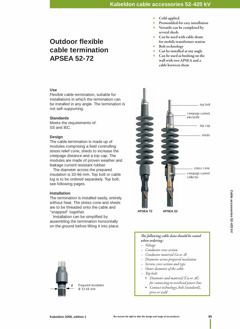
85Kabeldon 2009, edition 1 We reserve the right to alter the design and range of our products. We reserve the right to alter the design and range of our products.
Kabeldon cable accessories 1 kVNotesKabeldon cable accessories 52-420 kV
UseFlexible cable termination, suitable for installations in which the termination can be installed in any angle. The termination is not self-supporting.
StandardsMeets the requirements of:SS and IEC.
DesignThe cable termination is made up of modules comprising a fi eld controlling stress relief cone, sheds to increase the creepage distance and a top cap. The modules are made of proven weather and leakage current resistant rubber. The diameter across the prepared insulation is 33-66 mm. Top bolt or cable lug is to be ordered separately. Top bolt; see following pages.
InstallationThe termination is installed easily, entirely without heat. The stress cone and sheds are to be threaded onto the cable and "snapped" together. Installation can be simplifi ed by assembling the termination horizontally on the ground before lifting it into place.
Outdoor fl exible cable termination APSEA 52-72
stress cone
sheds
creepage current electrode
creepage current collector
Prepared insulationØ 33-66 mm
Th e following cable data should be stated when ordering:– Voltage– Conductor cross section– Conductor material Cu or Al– Diameter across prepared insulation– Screen, cross section and type– Outer diameter of the cable– Top bolt: • Diameter and material (Cu or Al) for connecting to overhead power line • Contact technology, bolt (standard), press or weld
top bolt
top cap
Ø
• Cold-applied• Premoulded for easy installation• Versatile can be completed by several sheds• Can be used with cable drum for mobile transformer station• Bolt technology• Can be installed at any angle • Can be used as bushing on the wall with two APSEA and a cable between them
APSEA 72 APSEA 52
Cab
le accessories 52-420 kV
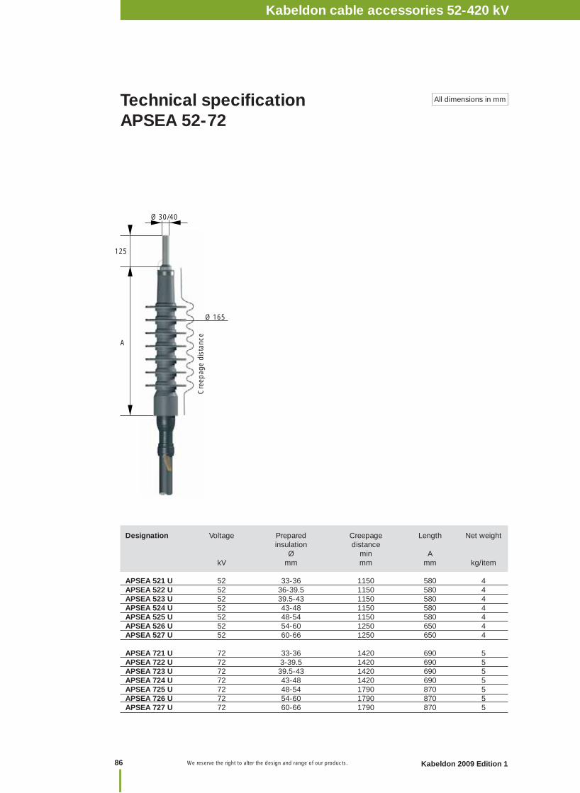
We reserve the right to alter the design and range of our products.
Designation Voltage Prepared Creepage Length Net weight insulation distance Ø min A kV mm mm mm kg/item
APSEA 521 U 52 33-36 1150 580 4APSEA 522 U 52 36-39.5 1150 580 4APSEA 523 U 52 39.5-43 1150 580 4APSEA 524 U 52 43-48 1150 580 4APSEA 525 U 52 48-54 1150 580 4APSEA 526 U 52 54-60 1250 650 4APSEA 527 U 52 60-66 1250 650 4
APSEA 721 U 72 33-36 1420 690 5APSEA 722 U 72 3-39.5 1420 690 5APSEA 723 U 72 39.5-43 1420 690 5APSEA 724 U 72 43-48 1420 690 5APSEA 725 U 72 48-54 1790 870 5APSEA 726 U 72 54-60 1790 870 5APSEA 727 U 72 60-66 1790 870 5
Technical specifi cationAPSEA 52-72
All dimensions in mm
125
A
Ø 30/40
Ø 165
Cre
epag
e di
stan
ce
Kabeldon cable accessories 1 kVNotes
86 Kabeldon 2009 Edition 1
Kabeldon cable accessories 52-420 kV
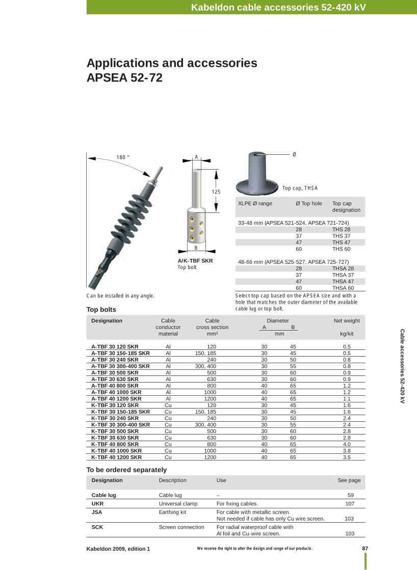
87Kabeldon 2009, edition 1 We reserve the right to alter the design and range of our products. We reserve the right to alter the design and range of our products.
Kabeldon cable accessories 1 kVNotesKabeldon cable accessories 52-420 kV
Applications and accessoriesAPSEA 52-72
Designation Cable Cable Diameter Net weight conductor cross section A B material mm² mm kg/kit
A-TBF 30 120 SKR Al 120 30 45 0.5A-TBF 30 150-185 SKR Al 150, 185 30 45 0.5A-TBF 30 240 SKR Al 240 30 50 0.8A-TBF 30 300-400 SKR Al 300, 400 30 55 0.8 A-TBF 30 500 SKR Al 500 30 60 0.9 A-TBF 30 630 SKR Al 630 30 60 0.9A-TBF 40 800 SKR Al 800 40 65 1.2A-TBF 40 1000 SKR Al 1000 40 65 1.2A-TBF 40 1200 SKR Al 1200 40 65 1.1K-TBF 30 120 SKR Cu 120 30 45 1.6K-TBF 30 150-185 SKR Cu 150, 185 30 45 1.6K-TBF 30 240 SKR Cu 240 30 50 2.4K-TBF 30 300-400 SKR Cu 300, 400 30 55 2.4K-TBF 30 500 SKR Cu 500 30 60 2.8 K-TBF 30 630 SKR Cu 630 30 60 2.8K-TBF 40 800 SKR Cu 800 40 65 4.0K-TBF 40 1000 SKR Cu 1000 40 65 3.8K-TBF 40 1200 SKR Cu 1200 40 65 3.5
A/K-TBF SKRTop bolt
180 °
Top bolts
B
A
125
XLPE Ø range Ø Top hole Top cap designation
33-48 mm (APSEA 521-524, APSEA 721-724) 28 THS 28 37 THS 37 47 THS 47 60 THS 60
48-66 mm (APSEA 525-527, APSEA 725-727) 28 THSA 28 37 THSA 37 47 THSA 47 60 THSA 60
Top cap, THSA
Ø
Select top cap based on the APSEA size and with a hole that matches the outer diameter of the available cable lug or top bolt.
Designation Description Use See page
Cable lug Cable lug – 59
UKR Universal clamp For fi xing cables. 107
JSA Earthing kit For cable with metallic screen. Not needed if cable has only Cu wire screen. 103
SCK Screen connection For radial waterproof cable with Al foil and Cu-wire screen. 103
To be ordered separately
Can be installed in any angle.
Cab
le accessories 52-420 kV

We reserve the right to alter the design and range of our products.
ØØ
Prepared insulation
Ø
APEGA 245APEGA 300APEGA 420
APEGA 170 APEGA 84
UseSuitable for installations where the termination is to be used as a fi xed connection point in gas-insulated switchgear, in transformers without a separate cable box or where the cable box is fi lled with transformer oil.
StandardsMeets the requirements of: SS, IEC, IEEE
DesignThe cable termination consists of an epoxy insulator standing on a base made of aluminium alloy. The fi eld controlling component is a stress cone made of rubber. The insulator is fi lled with synthetic insulating oil. A fl ange for insulated mounting is integrated in the epoxy insulator. A pressure ring is also included, see next page. For the maximum permissible diameter across the sheath of the cable and the diameter across the prepared cable insulation, see the table.
InstallationInstallation can be simplifi ed by assembling the termination horizontally on the ground before lifting it into place.
Cable termination for connection to gas-insulated switchgear (GIS) and transformers (TRF)APEGA 84-420
Th e following cable data should be stated when ordering:– Voltage– Conductor cross section– Conductor material Cu or Al– Diameter across prepared insulation– Screen, cross section and type (if optical fi bre)– Outer diameter of the cableType of connector:– Bolt (standard )– Weld (up to 170 kV)
• Reliable• Proven technique• Bolt technology • Can be assembled horizontally on the ground before installation • Flexible, fi ts big cables
Voltage Cable insulation Ø Oversheath min max Ø kV mm mm mm 84 25 66 85 170 45.5 100 150 245 73 120 160 300 73 120 160 420 73 120 160
APEGA 84
APEGA 245
APEGA 300
epoxy insulator
stress cone
box body
cable clamp
pressure ring
syntetic insulating oil
top fi tting
APEGA 170
APEGA 420
Kabeldon cable accessories 1 kVNotes
88 Kabeldon 2009 Edition 1
Kabeldon cable accessories 52-420 kV
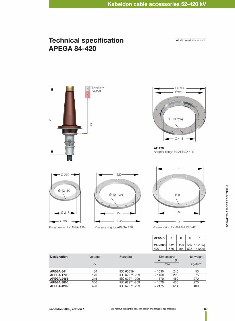
89Kabeldon 2009, edition 1 We reserve the right to alter the design and range of our products. We reserve the right to alter the design and range of our products.
Kabeldon cable accessories 1 kVNotesKabeldon cable accessories 52-420 kV
Designation Voltage Standard Dimensions Net weight A Ø kV mm kg/item APEGA 841 84 IEC 60859 ~ 1030 245 55APEGA 1703 170 IEC 62271-209 ~ 1460 298 75APEGA 2456 245 IEC 62271-209 ~ 1670 450 270APEGA 3006 300 IEC 62271-209 ~ 1670 450 270APEGA 4202 420 IEC 62271-209 ~ 2175 614 400
Technical specifi cationAPEGA 84-420
Pressure ring for APEGA 84.
All dimensions in mm
A
Pressure ring for APEGA 170.
Ø
Expansion vessel
AF 420Adapter fl ange for APEGA 420.
Pressure ring for APEGA 245-420.
APEGA a b c d
245-300 612 450 582 18 (16x)420 570 464 535 14 (20x)
Ø d
c
b
a
Ø 12 (8x)
Ø 270
Ø 217
Ø 300
Ø 19 (12x)
320
270
345
Ø 18 (20x)
Ø 640Ø 690
Ø 448
Cab
le accessories 52-420 kV

We reserve the right to alter the design and range of our products.
Technical specifi cation for connecting APEGA 84-420 to a transformer
Designation Voltage Dimensions Dimensions Weight standard A Ø kV mm kg/item APEGA 841 TRF 84 EN 50299 ~ 1150 245 55APEGA 1703 170 EN 50299 ~ 1580 298 75APEGA 245 245 EN 50299 ~ 1830 450 270APEGA 300 300 EN 50299 ~ 1830 450 270 APEGA 420 420 EN 50299 ~ 2335 614 400
AFT 1703Adapter fl ange for welding between APEGA 170 and transformer box.
32
Ø 370
8
Ø 220
Expansion vessel
A
Ø
CST 245-420Corona shield for installing APEGA 245-420 kV in transformer.
Designation Description Use
CST 84 Corona shield For installing APEGA 84 kV in transformerCST 170 Corona shield For installing APEGA 170 kV in transformer CST 245-420 Corona shield For installing APEGA 245-420 kV in transformerAFT 1703 Adapter fl ange Adapter fl ange to be welded between termination and transformer
To be ordered separately
CST 84, CST 170Corona shield for installing APEGA 84 kV and APEGA 170 kV in transformer.
Expansion vessel
A Ø
CST 84/CST 170
Dimension drawing for APEGA 245-420 kV.
Dimension drawing for APEGA 84-170 kV.
Kabeldon cable accessories 1 kVNotes
90 Kabeldon 2009 Edition 1
Kabeldon cable accessories 52-420 kV
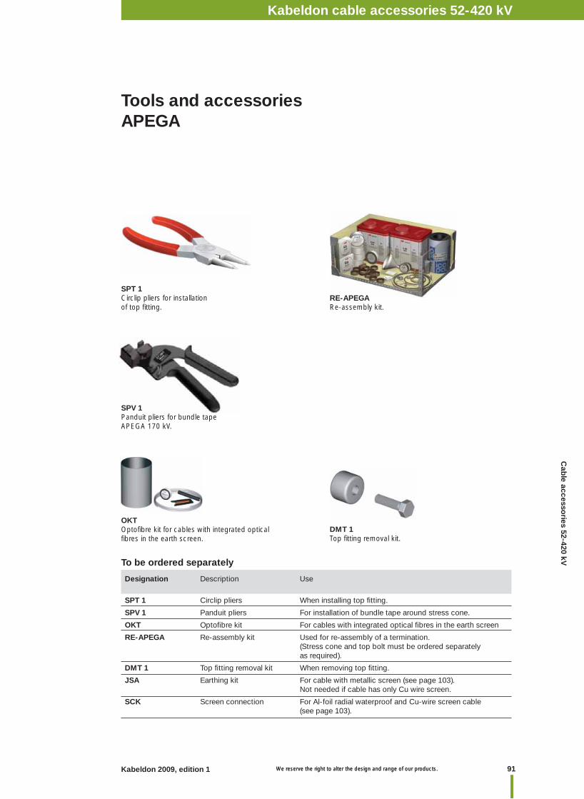
91Kabeldon 2009, edition 1 We reserve the right to alter the design and range of our products. We reserve the right to alter the design and range of our products.
Kabeldon cable accessories 1 kVNotesKabeldon cable accessories 52-420 kV
Tools and accessoriesAPEGA
Designation Description Use
SPT 1 Circlip pliers When installing top fi tting.
SPV 1 Panduit pliers For installation of bundle tape around stress cone.
OKT Optofi bre kit For cables with integrated optical fi bres in the earth screen
RE-APEGA Re-assembly kit Used for re-assembly of a termination. (Stress cone and top bolt must be ordered separately as required).
DMT 1 Top fi tting removal kit When removing top fi tting.
JSA Earthing kit For cable with metallic screen (see page 103). Not needed if cable has only Cu wire screen.
SCK Screen connection For Al-foil radial waterproof and Cu-wire screen cable (see page 103).
To be ordered separately
SPV 1Panduit pliers for bundle tapeAPEGA 170 kV.
RE-APEGARe-assembly kit.
DMT 1Top fi tting removal kit.
OKTOptofi bre kit for cables with integrated optical fi bres in the earth screen.
SPT 1Circlip pliers for installation of top fi tting.
Cab
le accessories 52-420 kV
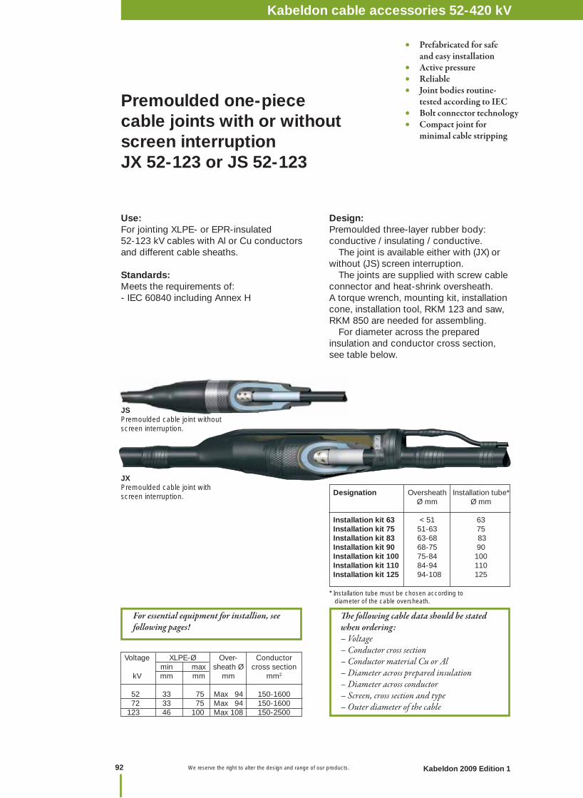
We reserve the right to alter the design and range of our products.
Th e following cable data should be stated when ordering:– Voltage– Conductor cross section– Conductor material Cu or Al– Diameter across prepared insulation– Diameter across conductor– Screen, cross section and type – Outer diameter of the cable
Premoulded one-piece cable joints with or without screen interruption JX 52-123 or JS 52-123
JSPremoulded cable joint without screen interruption.
Use:For jointing XLPE- or EPR-insulated 52-123 kV cables with Al or Cu conductors and different cable sheaths.
Standards:Meets the requirements of: - IEC 60840 including Annex H
• Prefabricated for safe and easy installation• Active pressure• Reliable• Joint bodies routine- tested according to IEC• Bolt connector technology• Compact joint for minimal cable stripping
Voltage XLPE-Ø Over- Conductor min max sheath Ø cross section kV mm mm mm mm2
52 33 75 Max 94 150-1600 72 33 75 Max 94 150-1600 123 46 100 Max 108 150-2500
For essential equipment for installion, see following pages!
JXPremoulded cable joint with screen interruption. Designation Oversheath Installation tube*
Ø mm Ø mm
Installation kit 63 < 51 63 Installation kit 75 51-63 75 Installation kit 83 63-68 83 Installation kit 90 68-75 90Installation kit 100 75-84 100Installation kit 110 84-94 110Installation kit 125 94-108 125
* Installation tube must be chosen according to diameter of the cable oversheath.
Design:Premoulded three-layer rubber body: conductive / insulating / conductive. The joint is available either with (JX) or without (JS) screen interruption. The joints are supplied with screw cable connector and heat-shrink oversheath.A torque wrench, mounting kit, installation cone, installation tool, RKM 123 and saw, RKM 850 are needed for assembling. For diameter across the prepared insulation and conductor cross section, see table below.
Kabeldon cable accessories 1 kVNotes
92 Kabeldon 2009 Edition 1
Kabeldon cable accessories 52-420 kV
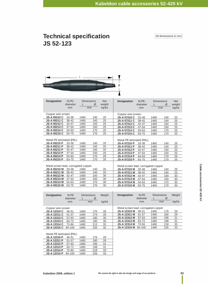
93Kabeldon 2009, edition 1 We reserve the right to alter the design and range of our products. We reserve the right to alter the design and range of our products.
Kabeldon cable accessories 1 kVNotesKabeldon cable accessories 52-420 kV
Designation XLPE- Dimensions Net diameter L Ø weight mm mm kg/kit
Copper wire screenJS-A 05210 C 33-38 1460 140 25JS-A 05211 C 38-42 1460 140 25JS-A 05212 C 42-47 1460 150 25JS-A 05213 C 47-54 1460 150 25JS-A 05214 C 54-63 1460 170 25JS-A 05215 C 63-75 1460 170 25
Metal-PE laminated (PAL)JS-A 05210 P 33-38 1460 140 25JS-A 05211 P 38-42 1460 140 25JS-A 05212 P 42-47 1460 150 25JS-A 05213 P 47-54 1460 150 25JS-A 05214 P 54-63 1460 170 25JS-A 05215 P 63-75 1460 170 25
Metal screen lead, corrugated copperJS-A 05210 M 33-38 1460 140 25JS-A 05211 M 38-42 1460 140 25JS-A 05212 M 42-47 1460 150 30JS-A 05213 M 47-54 1460 150 30JS-A 05214 M 54-63 1460 170 30JS-A 05215 M 63-75 1460 170 30
Technical specifi cationJS 52-123
All dimensions in mm
Designation XLPE- Dimensions Net diameter L Ø weight mm mm kg/kit
Copper wire screenJS-A 07210 C 33-38 1460 140 25JS-A 07211 C 38-42 1460 140 25JS-A 07212 C 42-47 1460 150 25JS-A 07213 C 47-54 1460 150 25JS-A 07214 C 54-63 1460 170 25JS-A 07215 C 63-75 1460 170 25
Metal-PE laminated (PAL)JS-A 07210 P 33-38 1460 140 25JS-A 07211 P 38-42 1460 140 25JS-A 07212 P 42-47 1460 150 25JS-A 07213 P 47-54 1460 150 25JS-A 07214 P 54-63 1460 170 25JS-A 07215 P 63-75 1460 170 25
Metal screen lead, corrugated copperJS-A 07210 M 33-38 1460 140 25JS-A 07211 M 38-42 1460 140 25JS-A 07212 M 42-47 1460 150 30JS-A 07213 M 47-54 1460 150 30JS-A 07214 M 54-63 1460 170 30JS-A 07215 M 63-75 1460 170 30
Designation XLPE Dimensions Weight diameter L Ø mm mm kg/kit
Copper wire screenJS-A 12310 C 46-51 1460 170 28JS-A 12311 C 51-57 1460 174 28JS-A 12312 C 57-63 1460 180 30JS-A 12313 C 63-72 1460 190 30JS-A 12314 C 72-84 1460 212 32JS-A 12315 C 84-100 1460 220 32
Metal-PE laminated (PAL)JS-A 12310 P 46-51 1460 176 29JS-A 12311 P 51-57 1460 180 29JS-A 12312 P 57-63 1460 195 31JS-A 12313 P 63-72 1460 198 31JS-A 12314 P 72-84 1460 218 33JS-A 12315 P 84-100 1460 226 33
Designation XLPE Dimensions Weight diameter L Ø mm mm kg/kit
Metal screen lead, corrugated copperJS-A 12310 M 46-51 1460 176 29JS-A 12311 M 51-57 1460 180 29JS-A 12312 M 57-63 1460 195 31JS-A 12313 M 63-72 1460 198 31JS-A 12314 M 72-84 1460 218 33JS-A 12315 M 84-100 1460 226 33
L
Ø
Cab
le accessories 52-420 kV
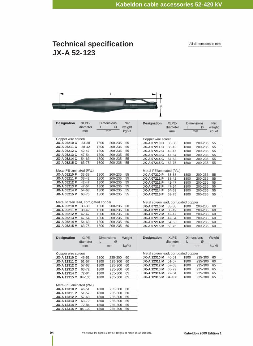
We reserve the right to alter the design and range of our products.
Designation XLPE- Dimensions Net diameter L Ø weight mm mm kg/kit
Copper wire screenJX-A 05210 C 33-38 1800 200-235 55 JX-A 05211 C 38-42 1800 200-235 55 JX-A 05212 C 42-47 1800 200-235 55JX-A 05213 C 47-54 1800 200-235 55JX-A 05214 C 54-63 1800 200-235 55JX-A 05215 C 63-75 1800 200-235 55
Metal-PE laminated (PAL)JX-A 05210 P 33-38 1800 200-235 55JX-A 05211 P 38-42 1800 200-235 55JX-A 05212 P 42-47 1800 200-235 55JX-A 05213 P 47-54 1800 200-235 55JX-A 05214 P 54-63 1800 200-235 55JX-A 05215 P 63-75 1800 200-235 55
Metal screen lead, corrugated copperJX-A 05210 M 33-38 1800 200-235 60JX-A 05211 M 38-42 1800 200-235 60JX-A 05212 M 42-47 1800 200-235 60JX-A 05213 M 47-54 1800 200-235 60JX-A 05214 M 54-63 1800 200-235 60JX-A 05215 M 63-75 1800 200-235 60
Designation XLPE- Dimensions Net diameter L Ø weight mm mm kg/kit
Copper wire screenJX-A 07210 C 33-38 1800 200-235 55JX-A 07211 C 38-42 1800 200-235 55JX-A 07212 C 42-47 1800 200-235 55JX-A 07213 C 47-54 1800 200-235 55JX-A 07214 C 54-63 1800 200-235 55JX-A 07215 C 63-75 1800 200-235 55
Metal-PE laminated (PAL)JX-A 07210 P 33-38 1800 200-235 55JX-A 07211 P 38-42 1800 200-235 55JX-A 07212 P 42-47 1800 200-235 55JX-A 07213 P 47-54 1800 200-235 55JX-A 07214 P 54-63 1800 200-235 55JX-A 07215 P 63-75 1800 200-235 55
Metal screen lead, corrugated copperJX-A 07210 M 33-38 1800 200-235 60JX-A 07211 M 38-42 1800 200-235 60JX-A 07212 M 42-47 1800 200-235 60JX-A 07213 M 47-54 1800 200-235 60JX-A 07214 M 54-63 1800 200-235 60JX-A 07215 M 63-75 1800 200-235 60
Designation XLPE Dimensions Weight diameter L Ø mm mm kg/kit
Copper wire screenJX-A 12310 C 46-51 1800 235-300 60JX-A 12311 C 51-57 1800 235-300 60JX-A 12312 C 57-63 1800 235-300 60JX-A 12313 C 63-72 1800 235-300 60JX-A 12314 C 72-84 1800 235-300 65JX-A 12315 C 84-100 1800 235-300 65
Metal-PE laminated (PAL)JX-A 12310 P 46-51 1800 235-300 60JX-A 12311 P 51-57 1800 235-300 60JX-A 12312 P 57-63 1800 235-300 65JX-A 12313 P 63-72 1800 235-300 65JX-A 12314 P 72-84 1800 235-300 65JX-A 12315 P 84-100 1800 235-300 65
Designation XLPE Dimensions Weight diameter L Ø mm mm kg/kit
Metal screen lead, corrugated copperJX-A 12310 M 46-51 1800 235-300 60JX-A 12311 M 51-57 1800 235-300 60JX-A 12312 M 57-63 1800 235-300 65JX-A 12313 M 63-72 1800 235-300 65JX-A 12314 M 72-84 1800 235-300 65JX-A 12315 M 84-100 1800 235-300 65
Technical specifi cationJX-A 52-123
All dimensions in mm
Ø
L
Kabeldon cable accessories 1 kVNotes
94 Kabeldon 2009 Edition 1
Kabeldon cable accessories 52-420 kV
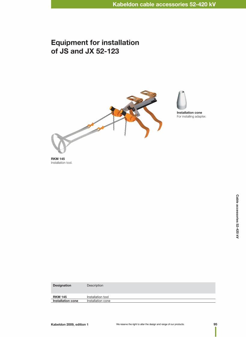
95Kabeldon 2009, edition 1 We reserve the right to alter the design and range of our products. We reserve the right to alter the design and range of our products.
Kabeldon cable accessories 1 kVNotesKabeldon cable accessories 52-420 kV
RKM 145Installation tool.
Equipment for installation of JS and JX 52-123
Designation Description
RKM 145 Installation tool Installation cone Installation cone
Installation coneFor installing adapter.
Cab
le accessories 52-420 kV
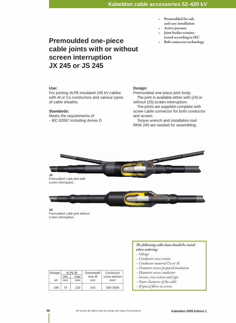
We reserve the right to alter the design and range of our products.
JXPremoulded cable joint with screen interruption.
Premoulded one-piece cable joints with or without screen interruptionJX 245 or JS 245
Voltage XLPE-Ø Oversheath Conductor min max max Ø cross section kV mm mm mm mm²
245 74 120 143 500-2500
Th e following cable data should be stated when ordering:– Voltage– Conductor cross section– Conductor material Cu or Al– Diameter across prepared insulation– Diameter across conductor– Screen, cross section and type – Outer diameter of the cable– If optical fi bres in screen
Use:For jointing XLPE-insulated 245 kV cables with Al or Cu conductors and various types of cable sheaths.
Standards:Meets the requirements of: - IEC 62067 including Annex D
• Premoulded for safe and easy installation• Active pressure• Joint bodies routine- tested according to IEC• Bolt connector technology
Design:Premoulded one-piece joint body. The joint is available either with (JX) or without (JS) screen interruption. The joints are supplied complete with screw cable connector for both conductor and screen. Torque wrench and installation toolRKM 245 are needed for assembling.
JSPremoulded cable joint without screen interruption.
Kabeldon cable accessories 1 kVNotes
96 Kabeldon 2009 Edition 1
Kabeldon cable accessories 52-420 kV
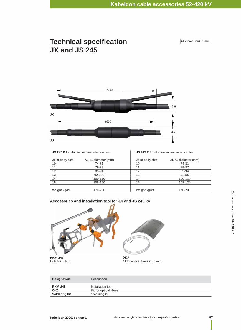
97Kabeldon 2009, edition 1 We reserve the right to alter the design and range of our products. We reserve the right to alter the design and range of our products.
Kabeldon cable accessories 1 kVNotesKabeldon cable accessories 52-420 kV
Technical specifi cation JX and JS 245
All dimensions in mm
JS 245 P for aluminium laminated cables
Joint body size XLPE-diameter (mm)10 74-81 11 79-87 12 85-94 13 92-102 14 100-11015 108-120
Weight kg/kit 170-200
JX 245 P for aluminium laminated cables
Joint body size XLPE-diameter (mm) 10 74-8111 79-87 12 85-94 13 92-102 14 100-110 15 108-120
Weight kg/kit 170-200
400
2730
JX
RKM 245Installation tool.
Designation Description RKM 245 Installation tool OKJ Kit for optical fi bresSoldering kit Soldering kit
OKJKit for optical fi bers in screen.
Accessories and installation tool for JX and JS 245 kV
2600
346
JS
Cab
le accessories 52-420 kV
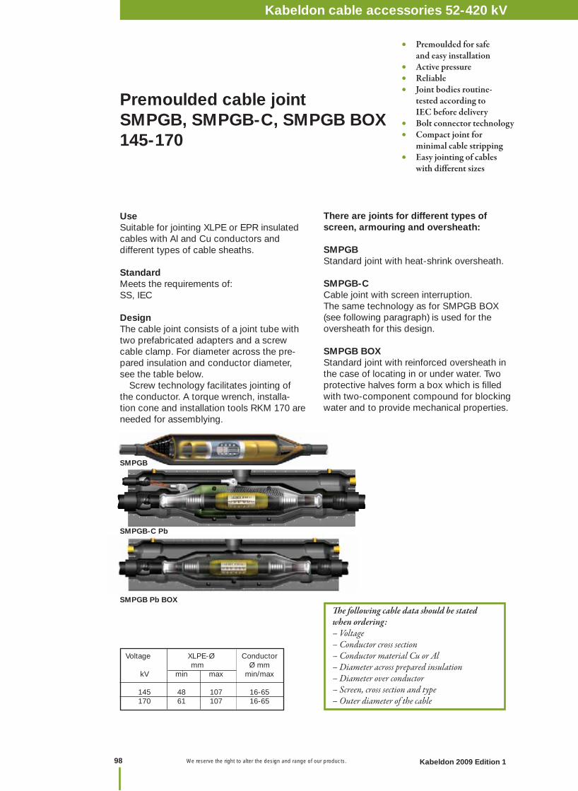
We reserve the right to alter the design and range of our products.
Premoulded cable joint SMPGB, SMPGB-C, SMPGB BOX145-170
Th e following cable data should be stated when ordering:– Voltage– Conductor cross section– Conductor material Cu or Al– Diameter across prepared insulation– Diameter over conductor– Screen, cross section and type– Outer diameter of the cable
• Premoulded for safe and easy installation• Active pressure• Reliable• Joint bodies routine- tested according to IEC before delivery• Bolt connector technology• Compact joint for minimal cable stripping• Easy jointing of cables with diff erent sizes
There are joints for different types of screen, armouring and oversheath:
SMPGB Standard joint with heat-shrink oversheath. SMPGB-C Cable joint with screen interruption.The same technology as for SMPGB BOX(see following paragraph) is used for the oversheath for this design. SMPGB BOX Standard joint with reinforced oversheath in the case of locating in or under water. Two protective halves form a box which is fi lled with two-component compound for blocking water and to provide mechanical properties.
UseSuitable for jointing XLPE or EPR insulated cables with Al and Cu conductors and different types of cable sheaths.
StandardMeets the requirements of: SS, IEC
DesignThe cable joint consists of a joint tube with two prefabricated adapters and a screw cable clamp. For diameter across the pre-pared insulation and conductor diameter, see the table below. Screw technology facilitates jointing of the conductor. A torque wrench, installa-tion cone and installation tools RKM 170 are needed for assemblying.
Voltage XLPE-Ø Conductor mm Ø mm kV min max min/max 145 48 107 16-65 170 61 107 16-65
SMPGB-C Pb
SMPGB Pb BOX
SMPGB
Kabeldon cable accessories 1 kVNotes
98 Kabeldon 2009 Edition 1
Kabeldon cable accessories 52-420 kV

99Kabeldon 2009, edition 1 We reserve the right to alter the design and range of our products. We reserve the right to alter the design and range of our products.
Kabeldon cable accessories 1 kVNotesKabeldon cable accessories 52-420 kV
Designation* Designation* Designation* Voltage XLPE Installation SMPGB SMPGB-C SMPGB diameter cone Standard Cross-bonding with BOX kV mm SMPGB 14501 – SMPGB 14501 BOX 145 48-51 4209.2384 SMPGB 14502 – SMPGB 14502 BOX 145 50-53 4209.2385 SMPGB 14503 – SMPGB 14503 BOX 145 52-56 4209.2386 SMPGB 14504 – SMPGB 14504 BOX 145 55-59 4209.2387 SMPGB 14505 – SMPGB 14505 BOX 145 58-62 4209.2388 SMPGB 14506 – SMPGB 14506 BOX 145 61-65 4209.2331 SMPGB 14507 – SMPGB 14507 BOX 145 63-68 4209.2332 SMPGB 14508 – SMPGB 14508 BOX 145 66-71 4209.2333 SMPGB 14509 – SMPGB 14509 BOX 145 69-76 4209.2334 SMPGB 14510 – SMPGB 14510 BOX 145 74-82 4209.2335 SMPGB 14511 – SMPGB 14511 BOX 145 80-91 4209.2336 SMPGB 14512 – SMPGB 14512 BOX 145 89-100 4209.2337 SMPGB 14513 – SMPGB 14513 BOX 145 98-107 4209.2400 SMPGB 1701 SMPGB-C 1701 SMPGB 1701 BOX 170 61-65 4209.2331 SMPGB 1702 SMPGB-C 1702 SMPGB 1702 BOX 170 63-68 4209.2332 SMPGB 1703 SMPGB-C 1703 SMPGB 1703 BOX 170 66-71 4209.2333 SMPGB 1704 SMPGB-C 1704 SMPGB 1704 BOX 170 69-76 4209.2334 SMPGB 1705 SMPGB-C 1705 SMPGB 1705 BOX 170 74-82 4209.2335 SMPGB 1706 SMPGB-C 1706 SMPGB 1706 BOX 170 80-91 4209.2336 SMPGB 1707 SMPGB-C 1707 SMPGB 1707 BOX 170 89-100 4209.2337 SMPGB 1708 SMPGB-C 1708 SMPGB 1708 BOX 170 98-107 4209.2400 * For lead-sheathed cable add Pb at the end of the type designation. For metal-PE laminated
cable with radial waterproofi ng, add PAL (e.g. SMPGB 1701 Pb, SMPGB 1701 PAL). For SMPGB with BOX; add Pb or PAL before BOX. For installation tool see next page.
Technical specifi cationSMPGB 145-170
All dimensions in mm
SMPGB L Ø mm 14501-14509 std 1300 20514510-14513 std 1950 20514501-14509 PAL 1600 21014510-14513 PAL 2250 21014501-14509 Pb 1620 245 14510-14513 Pb 2220 245
SMPGB Pb BOX
SMPGB
SMPGB-C Pb
B
B
SMPGB BOX L B/Ø mm14501-14505 Pb 1660 41014506-14513 Pb 1660 41014501-14513 PAL 1660 4101701-1704 Pb 1660 4101705-1708 Pb 1500 4101701-1704 PAL 1500 400
L
L
L
SMPGB-C L B/Ø mm1701-1704 Pb 1660 4101705-1708 Pb 1660 4101701-1704 PAL 1500 4001705-1708 PAL 2080 400
Ø
SMPGB L Ø mm 1701-1704 std 1300 2051705-1708 std 1950 2051701-1704 PAL 1600 2101705-1708 PAL 2250 2101701-1704 Pb 1650 2451705-1708 Pb 2220 245
Cab
le accessories 52-420 kV
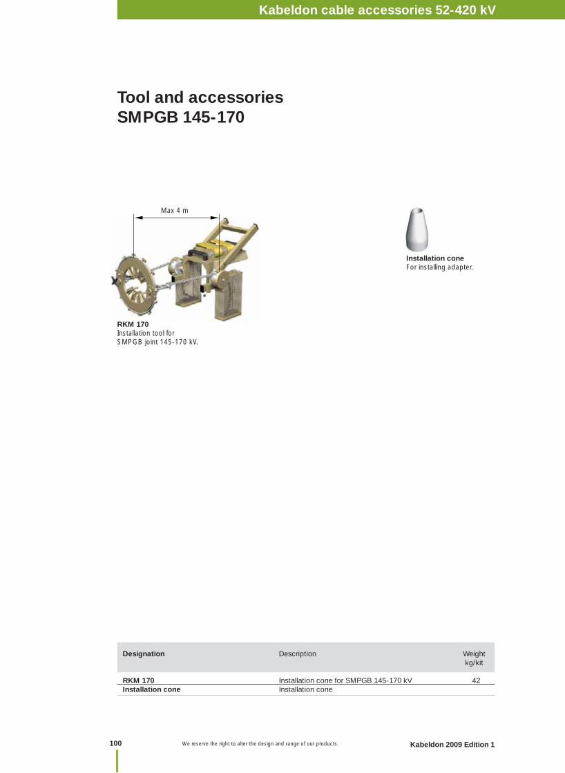
We reserve the right to alter the design and range of our products.
Tool and accessoriesSMPGB 145-170
Installation coneFor installing adapter.
Max 4 m
Designation Description Weight kg/kit RKM 170 Installation cone for SMPGB 145-170 kV 42 Installation cone Installation cone
RKM 170Installation tool for SMPGB joint 145-170 kV.
Kabeldon cable accessories 1 kVNotes
100 Kabeldon 2009 Edition 1
Kabeldon cable accessories 52-420 kV
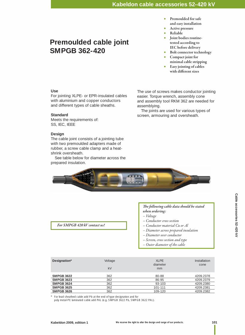
101Kabeldon 2009, edition 1 We reserve the right to alter the design and range of our products. We reserve the right to alter the design and range of our products.
Kabeldon cable accessories 1 kVNotesKabeldon cable accessories 52-420 kV
Designation* Voltage XLPE Installation diameter cone kV mm SMPGB 3622 362 80-88 4209.2378SMPGB 3623 362 86-95 4209.2379SMPGB 3624 362 93-103 4209.2380SMPGB 3625 362 101-111 4209.2381SMPGB 3626 362 109-120 4209.2382
* For lead sheathed cable add Pb at the end of type designation and for poly metal-PE laminated cable add PAL (e.g. SMPGB 3622 Pb, SMPGB 3622 PAL).
UseFor jointing XLPE- or EPR-insulated cables with aluminium and copper conductors and different types of cable sheaths.
StandardMeets the requirements of: SS, IEC, IEEE
DesignThe cable joint consists of a jointing tube with two premoulded adapters made of rubber, a screw cable clamp and a heat-shrink oversheath. See table below for diameter across the prepared insulation.
The use of screws makes conductor jointing easier. Torque wrench, assembly cone and assembly tool RKM 362 are needed for assemblying. The joints are used for various types of screen, armouring and oversheath.
Th e following cable data should be stated when ordering:– Voltage– Conductor cross section– Conductor material Cu or Al– Diameter across prepared insulation– Diameter over conductor– Screen, cross section and type– Outer diameter of the cable
Premoulded cable joint SMPGB 362-420
• Premoulded for safe and easy installation• Active pressure• Reliable• Joint bodies routine- tested according to IEC before delivery• Bolt connector technology• Compact joint for minimal cable stripping• Easy jointing of cables with diff erent sizes
For SMPGB 420 kV contact us!
Cab
le accessories 52-420 kV
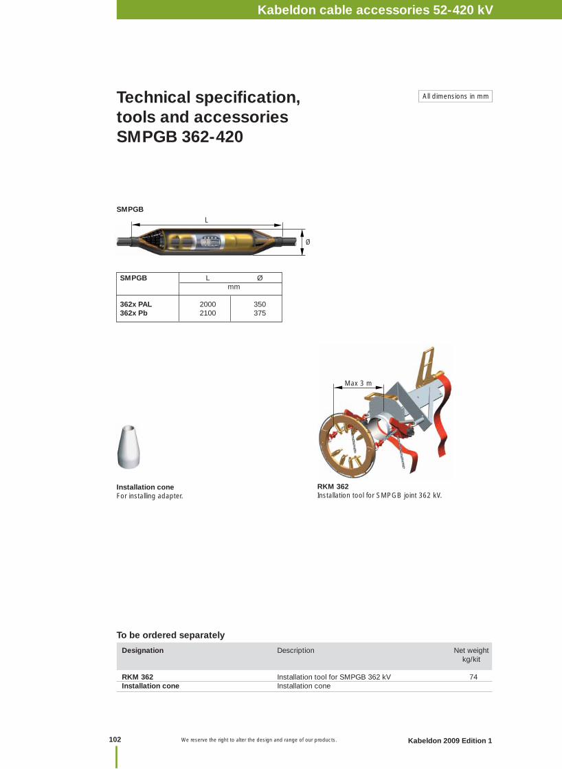
We reserve the right to alter the design and range of our products.
Technical specifi cation, tools and accessoriesSMPGB 362-420
SMPGB L Ø mm
362x PAL 2000 350362x Pb 2100 375
L
Ø
Installation coneFor installing adapter.
SMPGB
RKM 362Installation tool for SMPGB joint 362 kV.
Designation Description Net weight kg/kit RKM 362 Installation tool for SMPGB 362 kV 74Installation cone Installation cone
To be ordered separately
All dimensions in mm
Max 3 m
Kabeldon cable accessories 1 kVNotes
102 Kabeldon 2009 Edition 1
Kabeldon cable accessories 52-420 kV
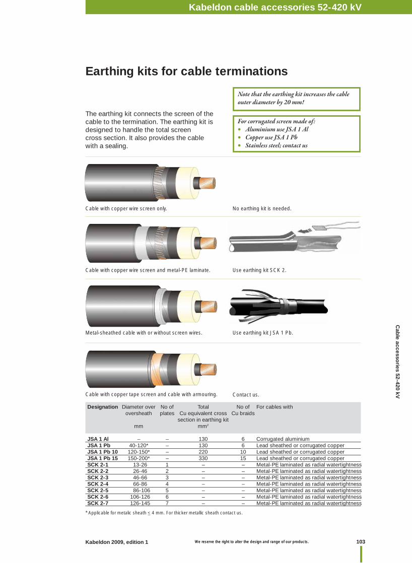
103Kabeldon 2009, edition 1 We reserve the right to alter the design and range of our products. We reserve the right to alter the design and range of our products.
Kabeldon cable accessories 1 kVNotesKabeldon cable accessories 52-420 kV
Designation Diameter over No of Total No of For cables with oversheath plates Cu equivalent cross Cu braids section in earthing kit mm mm2 JSA 1 Al – – 130 6 Corrugated aluminium JSA 1 Pb 40-120* – 130 6 Lead sheathed or corrugated copper JSA 1 Pb 10 120-150* – 220 10 Lead sheathed or corrugated copper JSA 1 Pb 15 150-200* – 330 15 Lead sheathed or corrugated copper SCK 2-1 13-26 1 – – Metal-PE laminated as radial watertightnessSCK 2-2 26-46 2 – – Metal-PE laminated as radial watertightnessSCK 2-3 46-66 3 – – Metal-PE laminated as radial watertightness SCK 2-4 66-86 4 – – Metal-PE laminated as radial watertightness SCK 2-5 86-106 5 – – Metal-PE laminated as radial watertightness SCK 2-6 106-126 6 – – Metal-PE laminated as radial watertightness SCK 2-7 126-145 7 – – Metal-PE laminated as radial watertightness
Earthing kits for cable terminations
The earthing kit connects the screen of the cable to the termination. The earthing kit is designed to handle the total screen cross section. It also provides the cable with a sealing.
Cable with copper wire screen only.
Cable with copper wire screen and metal-PE laminate.
Metal-sheathed cable with or without screen wires.
Cable with copper tape screen and cable with armouring.
For corrugated screen made of:• Aluminium use JSA 1 Al• Copper use JSA 1 Pb• Stainless steel; contact us
No earthing kit is needed.
Use earthing kit SCK 2.
Use earthing kit JSA 1 Pb.
Contact us.
Note that the earthing kit increases the cable outer diameter by 20 mm!
* Applicable for metalic sheath < 4 mm. For thicker metallic sheath contact us.
Cab
le accessories 52-420 kV

We reserve the right to alter the design and range of our products.
SKKBSKKB is a cross bonding kit for cables up to 170 kV. It can be mounted with advantage on already laid cable, where the load condition has changed and losses need to be reduced. Also gives the opportunity to optimize the cable system when cross-bonding can be chosen at a free position along the cable.
Accessories
Other dimensions on request.
Selection guide for ARMSelecting ARM for unknown applications requires the length of joint "L" and diameter over joint "Ø" as below:
E.g. Ø 115 and L 850 mm give ARM 3.
ARM kit size
The kit consists of plastic mesh, spiral, fun-nel with holder, transparent tape and cast resin. The mesh and spiral are placed over the joint and sealed with the tape. The cast resin, which contains base and hardener in a partitioned bag, is mixed and poured into the funnel until the mesh is full. The maximum storage temperature for the casting resin is 30 °C.
Designation Cable Ø Use
ARM – Armouring kit for armoured cableSKKB 5 PAL < 50 Al laminate as radially watertightnessSKKB 10 PAL 50-100 Al laminate as radially watertightnessSKKB 15 PAL 100-150 Al laminate as radially watertightnessSKKB 5 MET < 50 For metallic screen with or without Cu screen wiresSKKB 10 MET 50-100 For metallic screen with or without Cu screen wiresSKKB 15 MET 100-140 For metallic screen with or without Cu screen wiresSKKB 5 CUW < 50 Cu screenSKKB 10 CUW 50-100 Cu screenSKKB 15 CUW 100-150 Cu screen
All dimensions in mm
ARMFor restoring the armouring when jointing armoured cables.
Design:
Ø
L
500 1000 L (mm)
60
100
Ø (mm)
140
Kabeldon cable accessories 1 kVNotes
104 Kabeldon 2009 Edition 1
Kabeldon cable accessories 52-420 kV
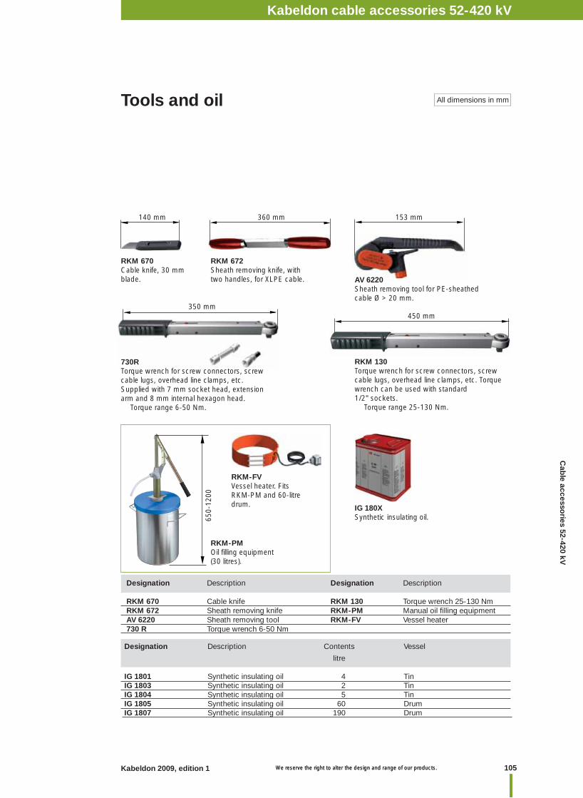
105Kabeldon 2009, edition 1 We reserve the right to alter the design and range of our products. We reserve the right to alter the design and range of our products.
Kabeldon cable accessories 1 kVNotesKabeldon cable accessories 52-420 kV
Tools and oil All dimensions in mm
AV 6220Sheath removing tool for PE-sheathed cable Ø > 20 mm.
RKM 670Cable knife, 30 mm blade.
RKM 672Sheath removing knife, with two handles, for XLPE cable.
140 mm 360 mm
350 mm
730RTorque wrench for screw connectors, screw cable lugs, overhead line clamps, etc. Supplied with 7 mm socket head, extension arm and 8 mm internal hexagon head. Torque range 6-50 Nm.
153 mm
450 mm
RKM 130Torque wrench for screw connectors, screw cable lugs, overhead line clamps, etc. Torque wrench can be used with standard 1/2" sockets. Torque range 25-130 Nm.
Designation Description Contents Vessel
litre
IG 1801 Synthetic insulating oil 4 TinIG 1803 Synthetic insulating oil 2 TinIG 1804 Synthetic insulating oil 5 TinIG 1805 Synthetic insulating oil 60 DrumIG 1807 Synthetic insulating oil 190 Drum
IG 180XSynthetic insulating oil.
RKM-FVVessel heater. Fits RKM-PM and 60-litre drum.
650-
1200
RKM-PMOil fi lling equipment (30 litres).
Designation Description Designation Description RKM 670 Cable knife RKM 130 Torque wrench 25-130 Nm RKM 672 Sheath removing knife RKM-PM Manual oil fi lling equipmentAV 6220 Sheath removing tool RKM-FV Vessel heater730 R Torque wrench 6-50 Nm
Cab
le accessories 52-420 kV
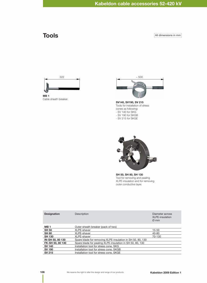
We reserve the right to alter the design and range of our products.
All dimensions in mmTools
Designation Description Diameter across XLPE-insulation Ø mm MB 1 Outer sheath breaker (pack of two)SH 50 XLPE-shaver 15-50SH 80 XLPE-shaver 40-80SH 130 XLPE-shaver 70-130IN-SH 50, 80 130 Spare blade for removing XLPE-insulation in SH 50, 80, 130 FK-SH 50, 80 130 Spare blade for pealing XLPE-insulation in SH 50, 80, 130SV 140 Installation tool for stress cone, SKG SV 190 Installation tool for stress cone, SKGB SV 215 Installation tool for stress cone, SKGE
SV140, SV190, SV 215Tools for installation of stress cones as following:- SV 140 for SKG- SV 190 for SKGB- SV 215 for SKGE
MB 1Cable sheath breaker.
~ 500322
SH 50, SH 80, SH 130Tool for removing and pealing XLPE-insulation and for removing outer conductive layer.
Kabeldon cable accessories 1 kVNotes
106 Kabeldon 2009 Edition 1
Kabeldon cable accessories 52-420 kV
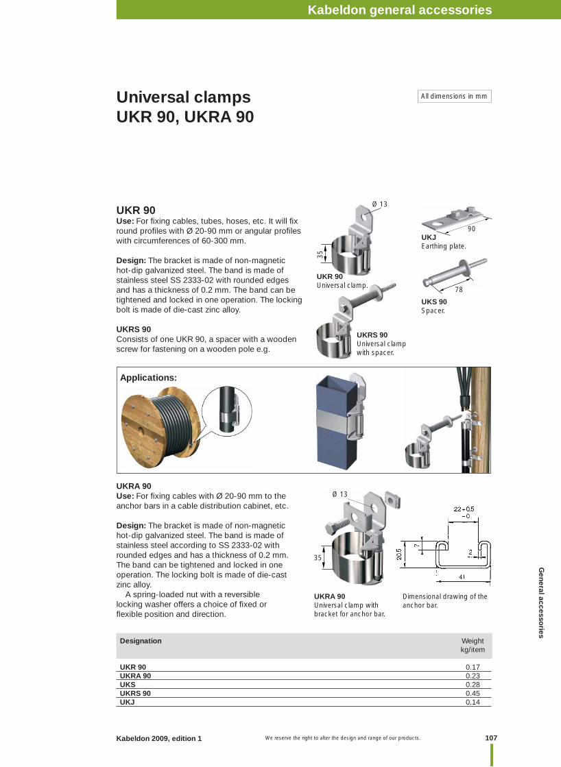
107Kabeldon 2009, edition 1 We reserve the right to alter the design and range of our products.
Dimensional drawing of the anchor bar.
UKR 90Use: For fi xing cables, tubes, hoses, etc. It will fi x round profi les with Ø 20-90 mm or angular profi les with circumferences of 60-300 mm.
Design: The bracket is made of non-magnetic hot-dip galvanized steel. The band is made of stainless steel SS 2333-02 with rounded edges and has a thickness of 0.2 mm. The band can be tightened and locked in one operation. The locking bolt is made of die-cast zinc alloy.
UKRS 90Consists of one UKR 90, a spacer with a wooden screw for fastening on a wooden pole e.g.
Universal clamps UKR 90, UKRA 90
Applications:
Designation Weight kg/item UKR 90 0.17UKRA 90 0.23UKS 0.28UKRS 90 0.45UKJ 0.14
UKRA 90Use: For fi xing cables with Ø 20-90 mm to the anchor bars in a cable distribution cabinet, etc.
Design: The bracket is made of non-magnetic hot-dip galvanized steel. The band is made of stainless steel according to SS 2333-02 with rounded edges and has a thickness of 0.2 mm. The band can be tightened and locked in one operation. The locking bolt is made of die-cast zinc alloy. A spring-loaded nut with a reversible locking washer offers a choice of fi xed or fl exible position and direction.
All dimensions in mm
Ø 13
35
90
Ø 13
35
78
UKR 90Universal clamp.
UKS 90Spacer.
UKJEarthing plate.
UKRS 90Universal clamp with spacer.
UKRA 90Universal clamp with bracket for anchor bar.
General accesso
riesKabeldon general accessories
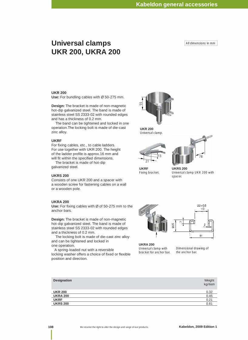
UKR 200Use: For bundling cables with Ø 50-275 mm.
Design: The bracket is made of non-magnetic hot-dip galvanized steel. The band is made of stainless steel SS 2333-02 with rounded edges and has a thickness of 0.2 mm. The band can be tightened and locked in one operation.The locking bolt is made of die-cast zinc alloy.
UKRFFor fi xing cables, etc., to cable ladders. For use together with UKR 200. The height of the ladder profi le is approx.16 mm and will fi t within the specifi ed dimensions. The bracket is made of hot-dip galvanized steel.
UKRS 200Consists of one UKR 200 and a spacer with a wooden screw for fastening cables on a wall or a wooden pole.
UKRA 200Use: For fi xing cables with Ø of 50-275 mm to the anchor bars.
Design: The bracket is made of non-magnetic hot-dip galvanized steel. The band is made of stainless steel SS 2333-02 with rounded edges and a thickness of 0.2 mm. The locking bolt is made of die-cast zinc alloy and can be tightened and locked in one operation. A spring-loaded nut with a reversible locking washer offers a choice of fi xed or fl exible position and direction.
UKR 200Universal clamp.
Universal clamps UKR 200, UKRA 200
Designation Weight kg/item UKR 200 0.32UKRA 200 0.45UKRF 0.21UKRS 200 0.81
UKRS 200Universal clamp UKR 200 with spacer.
UKRFFixing bracket.
All dimensions in mm
Dimensional drawing of the anchor bar.
55
21
13
55
78
UKRA 200Universal clamp with bracket for anchor bar.
Kabeldon cable accessories 1 kVNotes
108 Kabeldon, 2009 Edition 1 We reserve the right to alter the design and range of our products.
Kabeldon general accessories
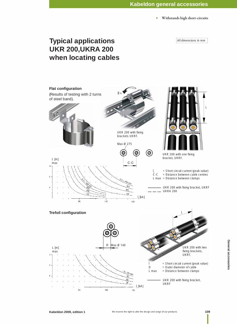
109Kabeldon 2009, edition 1 We reserve the right to alter the design and range of our products.
Typical applicationsUKR 200,UKRA 200when locating cables
All dimensions in mm
UKR 200 with fi xing brackets UKRF.
Trefoil confi guration
îs = Short circuit current (peak value)C-C = Distance between cable centresL max = Distance between clamps
UKR 200 with fi xing bracket, UKRFUKRA 200
î = Short circuit current (peak value)D = Outer diameter of cableL max = Distance between clamps
Max Ø 140
Max Ø 275
L [m]max
(Results of testing with 2 turns of steel band).
îs [kA]
îs [kA]
L [m]max
UKR 200 with two fi xing brackets, UKRF.
UKR 200 with one fi xing bracket, UKRF.
L
UKR 200 with fi xing bracket, UKRF
L
Flat confi guration
• Withstands high short-circuits
General accesso
riesKabeldon general accessories
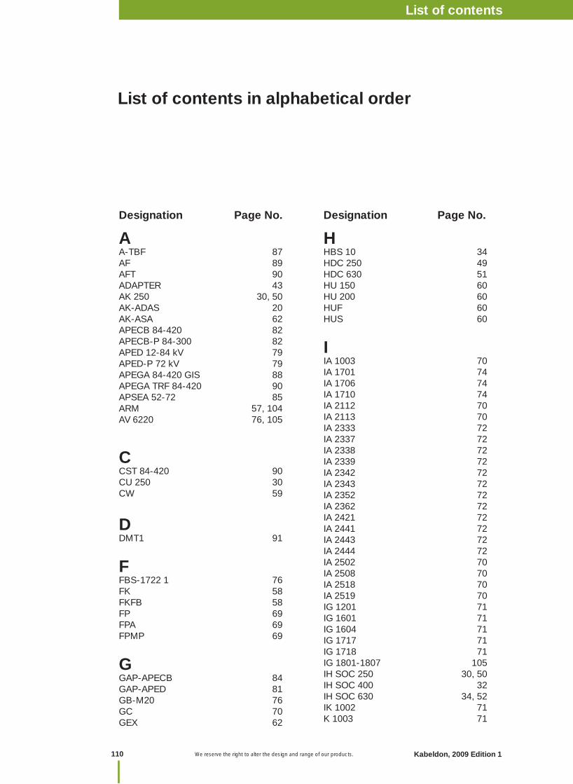
We reserve the right to alter the design and range of our products.
Designation Page No. Designation Page No.
AA-TBF 87AF 89AFT 90ADAPTER 43AK 250 30, 50AK-ADAS 20AK-ASA 62APECB 84-420 82APECB-P 84-300 82APED 12-84 kV 79APED-P 72 kV 79APEGA 84-420 GIS 88APEGA TRF 84-420 90APSEA 52-72 85ARM 57, 104AV 6220 76, 105
CCST 84-420 90CU 250 30CW 59
DDMT1 91
FFBS-1722 1 76FK 58FKFB 58FP 69FPA 69FPMP 69
GGAP-APECB 84GAP-APED 81GB-M20 76GC 70GEX 62
HHBS 10 34HDC 250 49HDC 630 51HU 150 60HU 200 60HUF 60HUS 60
IIA 1003 70IA 1701 74IA 1706 74IA 1710 74IA 2112 70IA 2113 70IA 2333 72IA 2337 72IA 2338 72IA 2339 72IA 2342 72IA 2343 72IA 2352 72IA 2362 72IA 2421 72IA 2441 72IA 2443 72IA 2444 72IA 2502 70IA 2508 70IA 2518 70IA 2519 70IG 1201 71IG 1601 71IG 1604 71IG 1717 71IG 1718 71IG 1801-1807 105IH SOC 250 30, 50IH SOC 400 32IH SOC 630 34, 52IK 1002 71K 1003 71
List of contents in alphabetical order
Kabeldon cable accessories 1 kVNotes
110 Kabeldon, 2009 Edition 1
List of contents
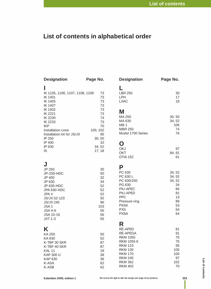
111Kabeldon 2009, edition 1 We reserve the right to alter the design and range of our products. 111 We reserve the right to alter the design and range of our products.
I IK 1105, 1106, 1107, 1108, 1109 73IK 1401 73IK 1405 73IK 1407 73IK 1502 73IK 2221 73IK 2230 74IK 2233 73IKP 70Installation cone 100, 102Installation kit for JS/JX 95IP 250 30, 50IP 400 32IP 630 34, 52IS 17, 18
JJP 250 30JP-250-HDC 50JP 400 32JP 630 34JP 630-HDC 52JPA 630-HDC 52JPA V 52JS/JX 52-123 92JS/JX 245 96JSA 1 103JSA 4-6 55JSA 10-16 56JXT 1-3 55
KKA 250 50KA 630 52K-TBF 30 SKR 87K-TBF 40 SKR 87KAL 11 19KAP 300 U 38KAP 630 36K-ASA 62K-ASB 62
LLBR 250 30LPH 17LXAC 18
MMA 250 30, 50MA 630 34, 52MB 1 106MBR 250 74Model 1700 Series 76
OOKJ 97OKT 84, 91OTIA 152 61
PPC 630 34, 52PC 630 L 34, 52PC 630/250 34, 52PG 630 34PIU-APEC 84PIU-APED 81PPC 13Pressure ring 89PSSK 53PXS 64PXSA 64
RRE-APED 81RE-APEGA 91RKM 1055 75RKM 1055 K 75RKM 123 95RKM 130 105RKM 170 100RKM 245 97RKM 362 102RKM 402 70
Designation Page No. Designation Page No.
List of contents in alphabetical order
Kabeldon cable accessories 1 kVList of contentsList o
f contents
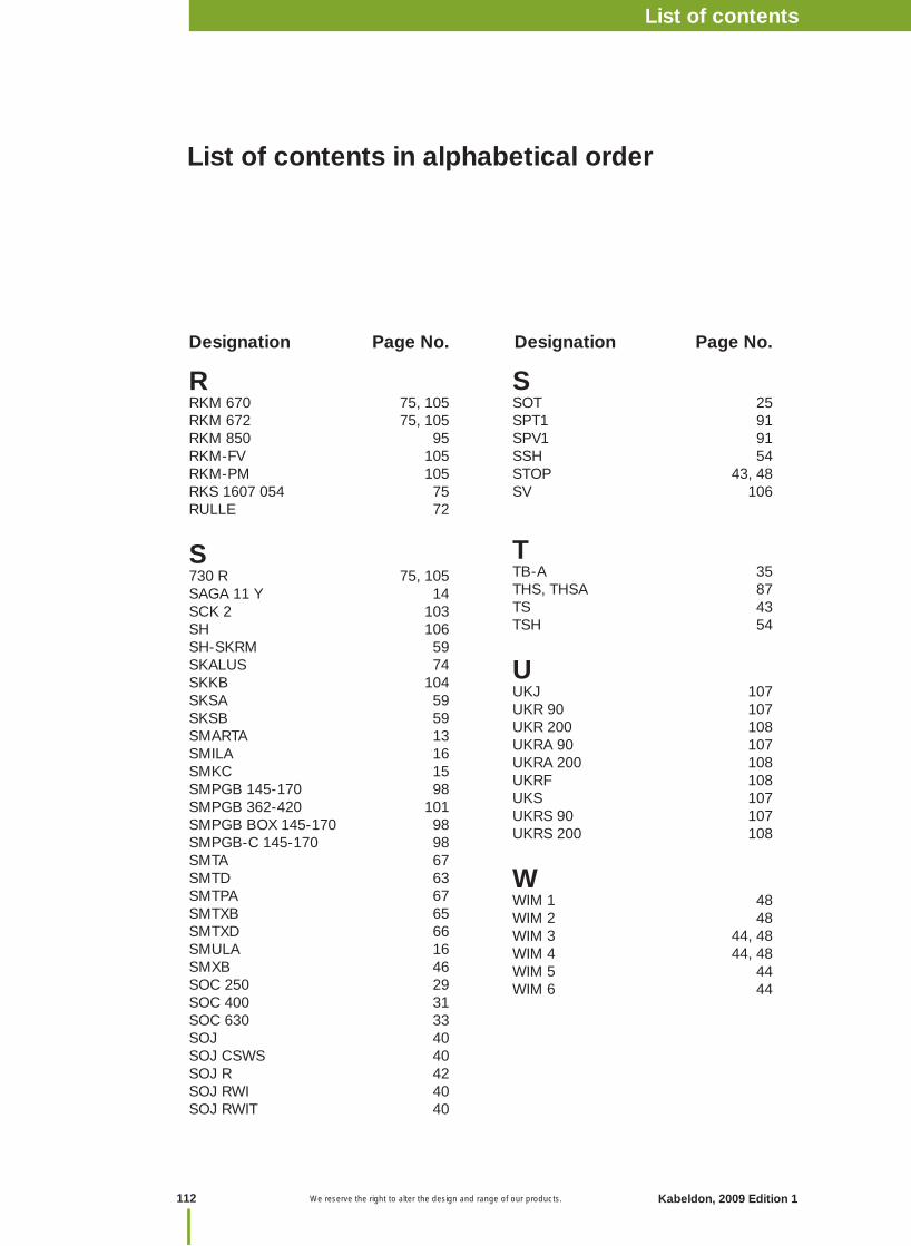
We reserve the right to alter the design and range of our products.
R RKM 670 75, 105 RKM 672 75, 105RKM 850 95RKM-FV 105RKM-PM 105RKS 1607 054 75RULLE 72
S730 R 75, 105SAGA 11 Y 14SCK 2 103SH 106SH-SKRM 59SKALUS 74SKKB 104SKSA 59SKSB 59SMARTA 13SMILA 16SMKC 15SMPGB 145-170 98SMPGB 362-420 101SMPGB BOX 145-170 98SMPGB-C 145-170 98SMTA 67SMTD 63SMTPA 67SMTXB 65SMTXD 66SMULA 16SMXB 46SOC 250 29SOC 400 31SOC 630 33SOJ 40 SOJ CSWS 40SOJ R 42SOJ RWI 40SOJ RWIT 40
Designation Page No. Designation Page No.
List of contents in alphabetical order
S SOT 25SPT1 91SPV1 91SSH 54STOP 43, 48SV 106
TTB-A 35THS, THSA 87TS 43 TSH 54
UUKJ 107UKR 90 107UKR 200 108UKRA 90 107UKRA 200 108UKRF 108UKS 107UKRS 90 107UKRS 200 108
WWIM 1 48WIM 2 48WIM 3 44, 48WIM 4 44, 48WIM 5 44WIM 6 44
Kabeldon cable accessories 1 kVNotes
112 Kabeldon, 2009 Edition 1
List of contents
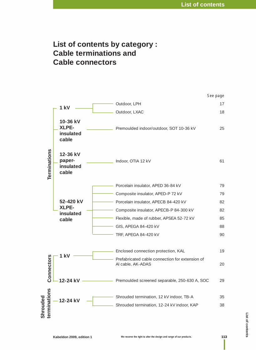
113Kabeldon 2009, edition 1 We reserve the right to alter the design and range of our products. 113 We reserve the right to alter the design and range of our products.
Term
inat
ions
See page
Outdoor, LPH 17
Outdoor, LXAC 18
Premoulded indoor/outdoor, SOT 10-36 kV 25
Indoor, OTIA 12 kV 61
Porcelain insulator, APED 36-84 kV 79
Composite insulator, APED-P 72 kV 79
Porcelain insulator, APECB 84-420 kV 82
Composite insulator, APECB-P 84-300 kV 82
Flexible, made of rubber, APSEA 52-72 kV 85
GIS, APEGA 84-420 kV 88
TRF, APEGA 84-420 kV 90
Enclosed connection protection, KAL 19
Prefabricated cable connection for extension of Al cable, AK-ADAS 20
Premoulded screened separable, 250-630 A, SOC 29
Shrouded termination, 12 kV indoor, TB-A 35
Shrouded termination, 12-24 kV indoor, KAP 38
List of contents by category :Cable terminations and Cable connectors
1 kV
12-36 kVpaper-insulated cable
10-36 kVXLPE-insulated cable
Co
nnec
tors 1 kV
12-24 kV
52-420 kVXLPE-insulated cable
12-24 kV
Shr
oud
ed
term
inat
ions
Kabeldon cable accessories 1 kVList of contentsList o
f contents
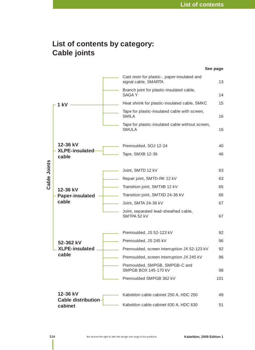
We reserve the right to alter the design and range of our products.
Cab
le J
oin
ts
See page
Cast resin for plastic-, paper-insulated and signal cable, SMARTA 13
Branch joint for plastic-insulated cable, SAGA Y 14
Heat shrink for plastic-insulated cable, SMKC 15
Tape for plastic-insulated cable with screen, SMILA 16
Tape for plastic-insulated cable without screen, SMULA 16
Premoulded, SOJ 12-24 40
Tape, SMXB 12-36 46
Joint, SMTD 12 kV 63
Repair joint, SMTD-RK 12 kV 63
Transition joint, SMTXB 12 kV 65
Transition joint, SMTXD 24-36 kV 66
Joint, SMTA 24-36 kV 67
Joint, separated lead-sheathed cable, SMTPA 52 kV 67
Premoulded, JS 52-123 kV 92
Premoulded, JS 245 kV 96
Premoulded, screen interruption JX 52-123 kV 92
Premoulded, screen interruption JX 245 kV 96
Premoulded, SMPGB, SMPGB-C and SMPGB BOX 145-170 kV 98
Premoulded SMPGB 362 kV 101
Kabeldon cable cabinet 250 A, HDC 250 49
Kabeldon cable cabinet 630 A, HDC 630 51
1 kV
12-36 kVXLPE-insulated cable
List of contents by category:Cable joints
12-36 kVPaper-insulated cable
52-362 kVXLPE-insulatedcable
12-36 kVCable distribution cabinet
Kabeldon cable accessories 1 kVNotes
114 Kabeldon, 2009 Edition 1
List of contents

115Kabeldon 2009, edition 1 We reserve the right to alter the design and range of our products. 115 We reserve the right to alter the design and range of our products.
Acc
esso
ries
See page
Screen separation kit, PSSK, PSSK-E 53
Branch seal for 3-core cable terminations 54
Earthing kit for terminations, JSA 4-6 and JXT 1-3 55
Screen connection for joints, JSA 10-16 56
Armouring kit, ARM 57
Overhead line clamp, FK 120 och FK 300 58
Screw cable lug, SKSA, SKSB 59
Screw connector, SH-SKRM 59
Spring-loaded gaskets, FPA, FP och FPMP 69
General accessories 70
Bird protection 60
Tapes 72
Other accessories 73
Tools 75
Earthing kits for cable terminations 103
Armouring kit, ARM 104
Tools and oil 105
UKR 90 107
UKRA 90 107
UKR 200 108
UKRA 200 108
List of contents by category:Accessories for cable accessories
Generalaccessories12-36 kV
Universal clamps
Accessories for cable accessories52-362 kV
Accessories forXLPE-insulated Cable accessories12-36 kV
Accessories for paper-insulatedcable accessories12-36 kV
Kabeldon cable accessories 1 kVList of contentsList o
f contents
Kabeldon cable accessories 1 kVNotes
IntroductionIntroductionKabeldon cable accessories 52-420 kVNotes

Kabeldon cable accessories 1 kVNotes

ABB ABKabeldonBox 531SE-441 15 Alingsås, SwedenTel: +46 322 770 00Fax: +46 322 770 01www.abb.se/kabeldon
® C
opyr
ight
200
9 A
BB
. All
right
s re
serv
ed.