Embed Size (px)
Citation preview
Kamina
RADIANT FLAME EFFECT GAS FIRE
Installation and Maintenance Instructions
Hand these instructions to the user
Model No’s FCRR10RN is for use on Natural Gas (G20) at a supplypressure of 20 mbar in G.B. / I.E.
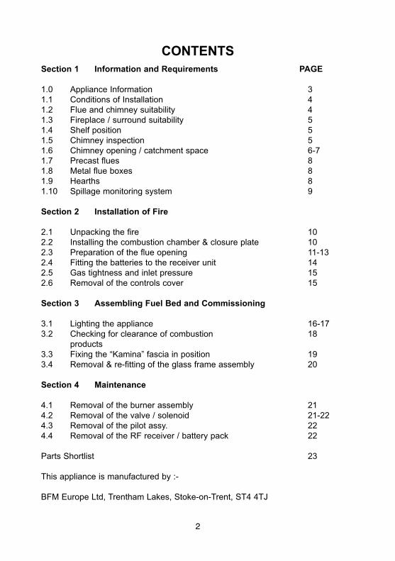
CONTENTSSection 1 Information and Requirements PAGE
1.0 Appliance Information 31.1 Conditions of Installation 41.2 Flue and chimney suitability 41.3 Fireplace / surround suitability 51.4 Shelf position 51.5 Chimney inspection 51.6 Chimney opening / catchment space 6-71.7 Precast flues 81.8 Metal flue boxes 81.9 Hearths 81.10 Spillage monitoring system 9
Section 2 Installation of Fire
2.1 Unpacking the fire 102.2 Installing the combustion chamber & closure plate 102.3 Preparation of the flue opening 11-132.4 Fitting the batteries to the receiver unit 142.5 Gas tightness and inlet pressure 152.6 Removal of the controls cover 15
Section 3 Assembling Fuel Bed and Commissioning
3.1 Lighting the appliance 16-173.2 Checking for clearance of combustion 18
products3.3 Fixing the “Kamina” fascia in position 193.4 Removal & re-fitting of the glass frame assembly 20
Section 4 Maintenance
4.1 Removal of the burner assembly 214.2 Removal of the valve / solenoid 21-224.3 Removal of the pilot assy. 224.4 Removal of the RF receiver / battery pack 22
Parts Shortlist 23
This appliance is manufactured by :-
BFM Europe Ltd, Trentham Lakes, Stoke-on-Trent, ST4 4TJ
2
SECTION 1INFORMATION AND REQUIREMENTS
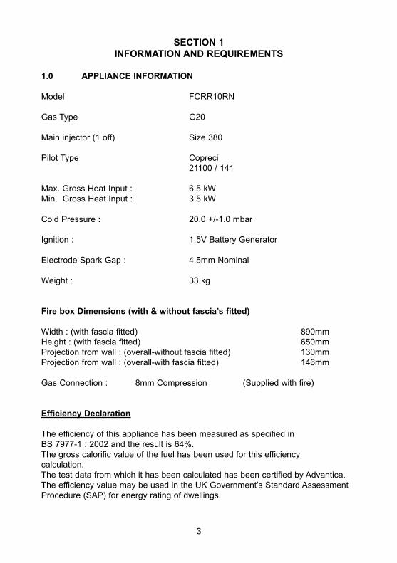
1.0 APPLIANCE INFORMATION
Model FCRR10RN
Gas Type G20
Main injector (1 off) Size 380
Pilot Type Copreci21100 / 141
Max. Gross Heat Input : 6.5 kWMin. Gross Heat Input : 3.5 kW
Cold Pressure : 20.0 +/-1.0 mbar
Ignition : 1.5V Battery Generator
Electrode Spark Gap : 4.5mm Nominal
Weight : 33 kg
Fire box Dimensions (with & without fascia’s fitted)
Width : (with fascia fitted) 890mmHeight : (with fascia fitted) 650mmProjection from wall : (overall-without fascia fitted) 130mmProjection from wall : (overall-with fascia fitted) 146mm
Gas Connection : 8mm Compression (Supplied with fire)
Efficiency Declaration
The efficiency of this appliance has been measured as specified inBS 7977-1 : 2002 and the result is 64%.The gross calorific value of the fuel has been used for this efficiencycalculation.The test data from which it has been calculated has been certified by Advantica.The efficiency value may be used in the UK Government’s Standard AssessmentProcedure (SAP) for energy rating of dwellings.
3
INSTALLATION REQUIREMENTS
1.1 CONDITIONS OF INSTALLATION
It is the law that all gas appliances are installed only by a GAS SAFE RegisteredInstaller, in accordance with these installation instructions and the Gas Safety(Installation and Use) Regulations 1998 as amended. Failure to install appliancescorrectly could lead to prosecution. It is in your own interest and that of safety tocomply with the law.
The installation must also be in accordance with all relevant parts of the Local andNational Building Regulations where appropriate, the Building Regulations(Scotland Consolidation) issued by the Scottish Development Department, and allapplicable requirements of the following British Standard Code of Practice.
1. B.S. 5871 Part 1 Installation of Radiant Convector Gas Fires2. B.S. 6891 Installation of Gas Pipework3. B.S. 5440 Parts 1 & 2 Installation of Flues and Ventilation4. B.S. 1251 Open fire place components5. B.S. 715 Metal flue pipes for gas appliances6. B.S. 6461 Part 1 Installation of Chimneys and flues7. B.S. E.N. 1858 Chinmeys Components & Concrete Flue Blocks8. I.S. 813 : 1996 Domestic Gas Installation (Republic of Ireland)
No purpose made additional ventilation is normally required for thisappliance, when installed in G.B. When Installing in I.E. please consultdocument I.S. 813 : 1996 Domestic Gas Installation, which is issued by theNational Standards Authority of Ireland. If installing in Northern Ireland,please consult local building regulations. Any purpose made ventilationmust be checked periodically to ensure that it is free from obstruction.
1.2 FLUE AND CHIMNEY SUITABILITY
This appliance is designed for use with conventional brick built or lined chimneysand fabricated flues. It is also suitable for use with pre-cast flue blocks conformingto BS EN 1858 and metal flue boxes conforming to BS 715. All flues mustconform to the following minimum dimensions.
Minimum diameter of circular flues 125 mm
Minimum effective height of all flue types 3 metres
Safe clearance of products must always be checked by carrying out a smokematch test as described.
4
1.3 FIREPLACE / SURROUND SUITABILITY
This fire can be installed with a fire surround in a conventional type installation(see page 11 for dimensional information) or without a fire surround, for a hang onthe wall type installation. It must not be installed directly onto carpet or othercombustible floor materials.The fire surround if installed must be manufactured from non-combustiblematerial and have a temperature rating of at least 150oc.If a heating appliance is fitted directly against a wall without the use of a firesurround or fire place all combustible material must be removed from behindthe Imagination fascia. Soft wall coverings such as blown vinyl, wall paperetc. will be affected by the rising hot air and scorching and / or discolorationwill result. Due consideration should be made to this when installing ordecorating.
1.4 SHELF POSITION
The fire may be fitted below a combustible shelf providing there is a minimumdistance of 200mm above the top of the fire and the shelf does not project morethan 150mm. If the shelf overhangs more than 150mm the distance between thefire and the shelf must be increased by 15mm for every 25mm of additionaloverhang over 150mm.
1.5 FLUE / CHIMNEY INSPECTION
Before commencing installation, a flue or chimney should be inspected to ensurethat all the following conditions are satisfied.
1. Check that the chimney / flue only serves one fire place and is clear of anyobstruction. Any dampers or register plates must be removed or locked inthe open position.
2. Brick/stone built chimneys or any chimney or flue which has been used foran appliance burning fuel other than gas must be thoroughly swept. Thebase of the chimney / flue must also be thoroughly cleared of debris etc.
3. Any under-floor air supply to the fire place must be completely sealed off.4. Ensure that the inside of the chimney / flue is in good condition along it’s
length and check that there is no leakage of smoke through the structureof the chimney during and after the smoke pellet test. With pre-cast fluesit is especially important to check the inside of the flue for extrudedcement / sealant protruding from the joints between the flueblocks. If present, these should be removed by rodding the fluebefore proceeding with the installation.
5. Using a smoke pellet, check that there is an up-draught in thechimney / flue and that the smoke can be seen issuing from theterminal / chimney pot outside.
5
There must be no leakage of smoke through the structure ofthe chimney during or after the smoke pellet test and it isimportant to check inside upstairs rooms adjacent to the chimney /flue. Check the chimney pot / terminal and general condition of thebrickwork or masonry. If the chimney or flue is in poor condition or ifthere is no up-draught do not proceed with the installation. If there is ahistory of down-draught conditions with the chimney / flue, a tested andcertificated flue terminal or cowl suitable for the relevant flue type shouldbe considered.
6. A spillage test must always be carried out during commissioning ofthe appliance.
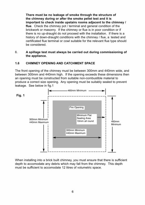
1.6 CHIMNEY OPENING AND CATCHMENT SPACE
The front opening of the chimney must be between 300mm and 440mm wide, andbetween 300mm and 440mm high. If the opening exceeds these dimensions thenan opening must be constructed from suitable non-combustible material toproduce a correct size opening. Any opening must be suitably sealed to preventleakage. See below in fig.1
When installing into a brick built chimney, you must ensure that there is sufficientdepth to accomodate any debris which may fall from the chimney. This depthmust be sufficient to accomodate 12 litres of volumetric space.
Fire Opening
300mm Minimum440mm Maximum
Fig. 1
300mm Minimum440mm Maximum
Minimum FlatSealing Area10mm all round
6
460mmMinimum
460mm Minimum
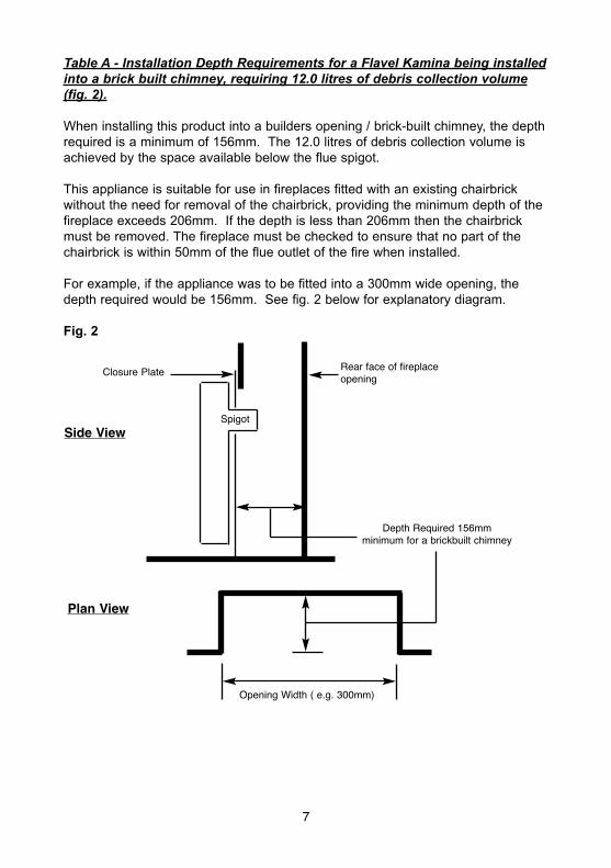
Table A - Installation Depth Requirements for a Flavel Kamina being installedinto a brick built chimney, requiring 12.0 litres of debris collection volume(fig. 2).
When installing this product into a builders opening / brick-built chimney, the depthrequired is a minimum of 156mm. The 12.0 litres of debris collection volume isachieved by the space available below the flue spigot.
This appliance is suitable for use in fireplaces fitted with an existing chairbrickwithout the need for removal of the chairbrick, providing the minimum depth of thefireplace exceeds 206mm. If the depth is less than 206mm then the chairbrickmust be removed. The fireplace must be checked to ensure that no part of thechairbrick is within 50mm of the flue outlet of the fire when installed.
For example, if the appliance was to be fitted into a 300mm wide opening, thedepth required would be 156mm. See fig. 2 below for explanatory diagram.
Fig. 2
7
Opening Width ( e.g. 300mm)
Depth Required 156mmminimum for a brickbuilt chimney
Rear face of fireplaceopening
Spigot
Closure Plate
Side View
Plan View
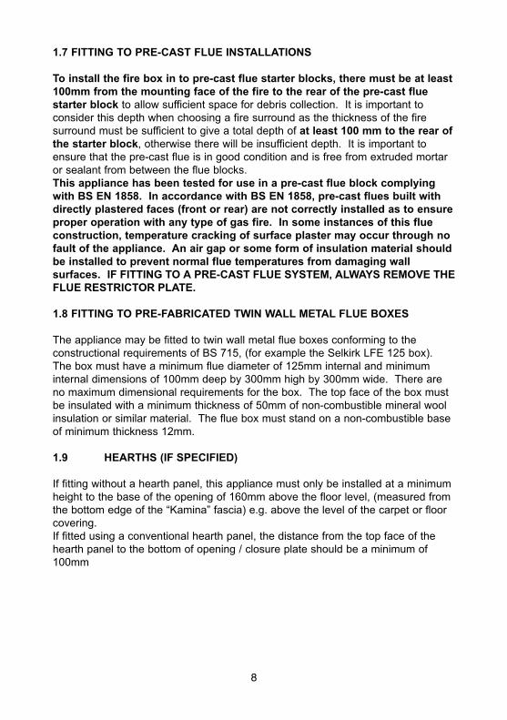
1.7 FITTING TO PRE-CAST FLUE INSTALLATIONS
To install the fire box in to pre-cast flue starter blocks, there must be at least100mm from the mounting face of the fire to the rear of the pre-cast fluestarter block to allow sufficient space for debris collection. It is important toconsider this depth when choosing a fire surround as the thickness of the firesurround must be sufficient to give a total depth of at least 100 mm to the rear ofthe starter block, otherwise there will be insufficient depth. It is important toensure that the pre-cast flue is in good condition and is free from extruded mortaror sealant from between the flue blocks.This appliance has been tested for use in a pre-cast flue block complyingwith BS EN 1858. In accordance with BS EN 1858, pre-cast flues built withdirectly plastered faces (front or rear) are not correctly installed as to ensureproper operation with any type of gas fire. In some instances of this flueconstruction, temperature cracking of surface plaster may occur through nofault of the appliance. An air gap or some form of insulation material shouldbe installed to prevent normal flue temperatures from damaging wallsurfaces. IF FITTING TO A PRE-CAST FLUE SYSTEM, ALWAYS REMOVE THEFLUE RESTRICTOR PLATE.
1.8 FITTING TO PRE-FABRICATED TWIN WALL METAL FLUE BOXES
The appliance may be fitted to twin wall metal flue boxes conforming to theconstructional requirements of BS 715, (for example the Selkirk LFE 125 box).The box must have a minimum flue diameter of 125mm internal and minimuminternal dimensions of 100mm deep by 300mm high by 300mm wide. There areno maximum dimensional requirements for the box. The top face of the box mustbe insulated with a minimum thickness of 50mm of non-combustible mineral woolinsulation or similar material. The flue box must stand on a non-combustible baseof minimum thickness 12mm.
1.9 HEARTHS (IF SPECIFIED)
If fitting without a hearth panel, this appliance must only be installed at a minimumheight to the base of the opening of 160mm above the floor level, (measured fromthe bottom edge of the “Kamina” fascia) e.g. above the level of the carpet or floorcovering.If fitted using a conventional hearth panel, the distance from the top face of thehearth panel to the bottom of opening / closure plate should be a minimum of100mm
8
1.10 SPILLAGE MONITORING SYSTEM
This appliance is fitted with an atmosphere sensing spillage monitoring system inthe form of an oxygen sensing pilot. This is designed to shut the fire off in theevent of a partial or complete blockage of the flue causing a build up ofcombustion products in the room in which the fire is operated. The following areimportant warnings relating to this spillage monitoring system :-
1) The spillage monitoring system must not be adjusted by the installer.
2) The spillage monitoring system must not be put out of operation.
3) When the spillage monitoring system is exchanged only a complete originalmanufacturers part may be fitted. It is not possible to replace individual parts onthe pilot system on this appliance, only a complete pilot assembly (including thethermocouple) may be fitted.
9
SECTION 2INSTALLATION OF FIRE
2.1 UNPACKING THE FIRE
Carefully lift the fire out of the carton. Remove the loose item packaging carefullyfrom the front of the appliance. Check the contents as listed :-
Packing Check List
1 off Combustion chamber and glass frame assembly1 off Loose items bag including :-
1 off Remote control handset1 off 6mm Allen key1 off each User instruction book and Installation book4 off 1.5V Batteries1 off Spigot & fitting screws1 off valve cover2 off M5 screws (to fit fascia to base brackets)
1 off Kamina Fascia1 off Closure Plate
2.2 INSTALLING THE COMBUSTION CHAMBER & CLOSURE PLATE
Establish which type of flue you are intending to install the fire in to :-
225 x 225mm (9 inch x 9 inch) brick built chimneys175mm (7 inch) diameter lined brick or stone flue, or insulated pre-fabricatedmetal flue box to B.S. 715.
When installing into 125mm (5 inch) diameter lined brick or stone flue, orinsulated pre-fabricated metal flue box to B.S. 715 and pre-cast flues therestrictor baffle must not be fitted.
A spillage test must always be carried out to check satisfactoryclearance of flue products, regardless of the type of flue theappliance is being fitted to.
PLEASE NOTE :- IF INSTALLING THIS PRODUCT INTO A HOLE IN THE WALLTYPE INSTALLATION IN WHICH THE FLUE TYPE IS PRE-CAST, SPECIALISTADVICE MUST BE OBTAINED FROM A STRUCTURAL ENGINEERREGARDING THE RE-POSITIONING OF THE STARTER BLOCKS.
UNDER NO CIRCUMSTANCES SHOULD THE FIRE BE RECESSED INTO THEGATHER BLOCK, OFFSET OR STRAIGHT FLUE BLOCKS.
10
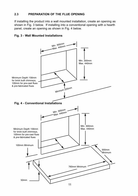
2.3 PREPARATION OF THE FLUE OPENING
If installing the product into a wall mounted installation, create an opening asshown in Fig. 3 below. If installing into a conventional opening with a hearthpanel, create an opening as shown in Fig. 4 below.
Fig. 3 - Wall Mounted Installations
Fig. 4 - Conventional Installations
Minmum225mm
Min. 300mm
Max. 440mm
Min. 300mmMax. 440mm
Min. 300mm
Max. 440mm
Min. 300mmMax. 440mm
100mm Minimum
50mm
300mmMinimum
11
760mm Minimum
Minimum Depth 156mmfor brick built chimneys,100mm for pre-cast flues& pre-fabricated flues
Minimum Depth 156mmfor brick built chimneys,100mm for pre-cast flues& pre-fabricated flues
Proceed as follows :-
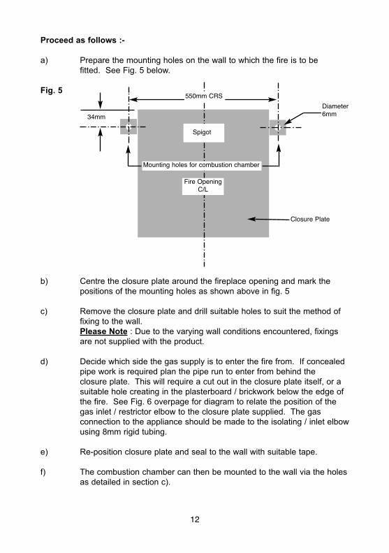
a) Prepare the mounting holes on the wall to which the fire is to befitted. See Fig. 5 below.
Fig. 5
b) Centre the closure plate around the fireplace opening and mark thepositions of the mounting holes as shown above in fig. 5
c) Remove the closure plate and drill suitable holes to suit the method offixing to the wall.Please Note : Due to the varying wall conditions encountered, fixingsare not supplied with the product.
d) Decide which side the gas supply is to enter the fire from. If concealedpipe work is required plan the pipe run to enter from behind theclosure plate. This will require a cut out in the closure plate itself, or asuitable hole creating in the plasterboard / brickwork below the edge ofthe fire. See Fig. 6 overpage for diagram to relate the position of thegas inlet / restrictor elbow to the closure plate supplied. The gasconnection to the appliance should be made to the isolating / inlet elbowusing 8mm rigid tubing.
e) Re-position closure plate and seal to the wall with suitable tape.
f) The combustion chamber can then be mounted to the wall via the holesas detailed in section c).
12
Spigot
Fire OpeningC/L
Closure Plate
34mm
550mm CRS
Mounting holes for combustion chamber
Diameter6mm
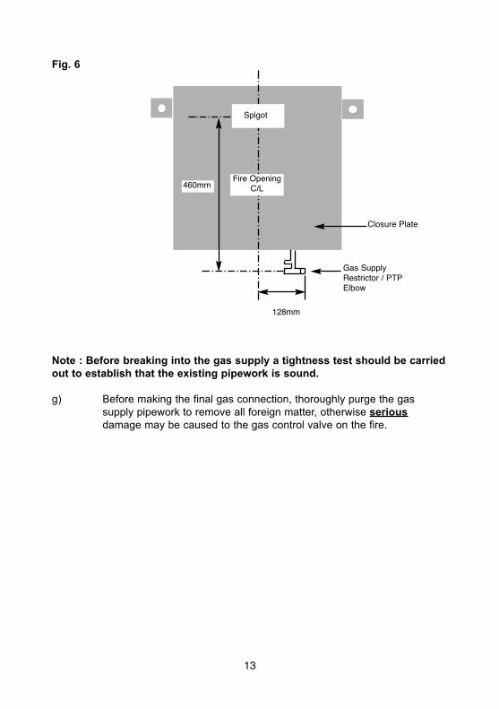
Fig. 6
Note : Before breaking into the gas supply a tightness test should be carriedout to establish that the existing pipework is sound.
g) Before making the final gas connection, thoroughly purge the gassupply pipework to remove all foreign matter, otherwise seriousdamage may be caused to the gas control valve on the fire.
13
Spigot
Fire OpeningC/L
Closure Plate
Gas SupplyRestrictor / PTPElbow
460mm
128mm
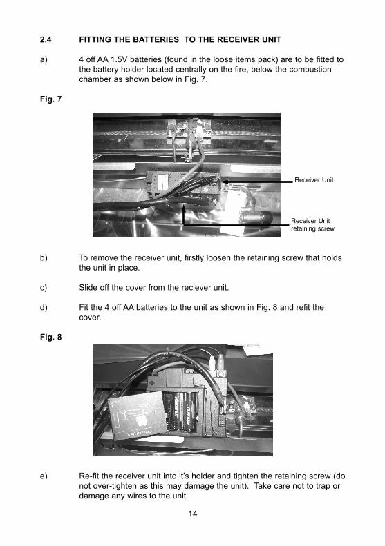
2.4 FITTING THE BATTERIES TO THE RECEIVER UNIT
a) 4 off AA 1.5V batteries (found in the loose items pack) are to be fitted tothe battery holder located centrally on the fire, below the combustionchamber as shown below in Fig. 7.
Fig. 7
b) To remove the receiver unit, firstly loosen the retaining screw that holdsthe unit in place.
c) Slide off the cover from the reciever unit.
d) Fit the 4 off AA batteries to the unit as shown in Fig. 8 and refit thecover.
Fig. 8
e) Re-fit the receiver unit into it’s holder and tighten the retaining screw (donot over-tighten as this may damage the unit). Take care not to trap ordamage any wires to the unit.
14
Receiver Unit
Receiver Unitretaining screw
2.5 GAS TIGHTNESS AND INLET PRESSURE
a) Remove the pressure test point screw from the inlet elbow and fit amanometer.
b) Turn on the main gas supply and carry out a gas tightness test.
c) Depress both the round buttons on the handset. The fire will thencommence its ignition sequence and will light to high. See page 15 / 16for full details of the operating method for the fire.
d) Check that the gas pressure is 20.0 mbar (+/- 1.0mbar) 8.0 in w.g.(+/-0.4 in w.g.)
e) Turn off the fire, remove the manometer and refit the pressure test pointscrew. Check the pressure test point screw for gas tightness with theappliance turned on using a suitable leak detection fluid or detector.
2.6 REMOVAL OF THE CONTROLS COVER
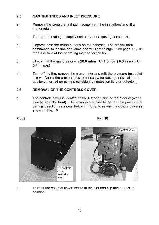
a) The controls cover is located on the left hand side of the product (whenviewed from the front). The cover is removed by gently lifting away in avertical direction as shown below in Fig. 9, to reveal the control valve asshown in Fig. 10
Fig. 9 Fig. 10
b) To re-fit the controls cover, locate in the slot and clip and fit back inposition.
15
Lift controlscoververticallyaway
Control valve
SECTION 3COMMISSIONING OF THE FIRE
3.1 LIGHTING THE APPLIANCE
a) The control valve is positioned on the left hand side of the fire whenviewed from the front.
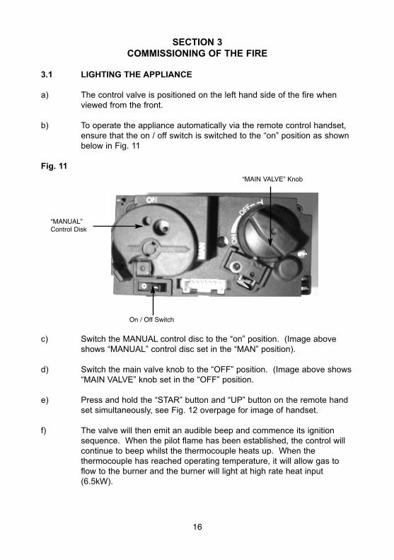
b) To operate the appliance automatically via the remote control handset,ensure that the on / off switch is switched to the “on” position as shownbelow in Fig. 11
Fig. 11
c) Switch the MANUAL control disc to the “on” position. (Image aboveshows “MANUAL” control disc set in the “MAN” position).
d) Switch the main valve knob to the “OFF” position. (Image above shows“MAIN VALVE” knob set in the “OFF” position.
e) Press and hold the “STAR” button and “UP” button on the remote handset simultaneously, see Fig. 12 overpage for image of handset.
f) The valve will then emit an audible beep and commence its ignitionsequence. When the pilot flame has been established, the control willcontinue to beep whilst the thermocouple heats up. When thethermocouple has reached operating temperature, it will allow gas toflow to the burner and the burner will light at high rate heat input(6.5kW).
16
On / Off Switch
“MANUAL”Control Disk
“MAIN VALVE” Knob
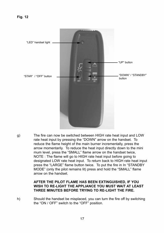
Fig. 12
g) The fire can now be switched between HIGH rate heat input and LOWrate heat input by pressing the “DOWN” arrow on the handset. Toreduce the flame height of the main burner incrementally, press thearrow momentarily. To reduce the heat input directly down to the minimum level, press the “SMALL” flame arrow on the handset twice,NOTE : The flame will go to HIGH rate heat input before going todesignated LOW rate heat input. To return back to HIGH rate heat inputpress the “LARGE” flame button twice. To put the fire in In “STANDBYMODE” (only the pilot remains lit) press and hold the “SMALL” flamearrow on the handset.
AFTER THE PILOT FLAME HAS BEEN EXTINGUISHED, IF YOUWISH TO RE-LIGHT THE APPLIANCE YOU MUST WAIT AT LEASTTHREE MINUTES BEFORE TRYING TO RE-LIGHT THE FIRE.
h) Should the handset be misplaced, you can turn the fire off by switchingthe “ON / OFF” switch to the “OFF” position.
17
“STAR” / “OFF” button
“UP” button
“DOWN” / “STANDBY”button
“LED” handset light
3.2 CHECKING FOR CLEARANCE OF COMBUSTION PRODUCTS
a) Close all doors and windows in the room.b) Light the fire and allow to run for approximately 5 minutes on high
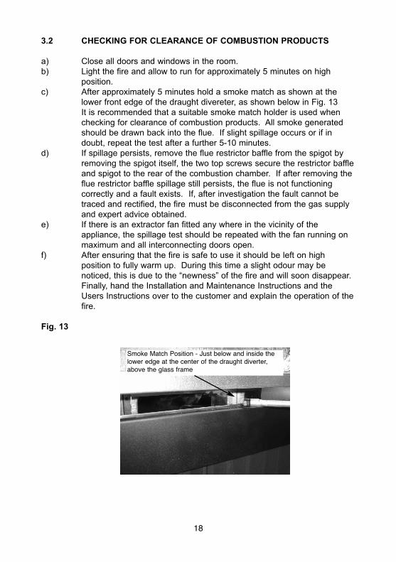
position.c) After approximately 5 minutes hold a smoke match as shown at the
lower front edge of the draught divereter, as shown below in Fig. 13It is recommended that a suitable smoke match holder is used whenchecking for clearance of combustion products. All smoke generatedshould be drawn back into the flue. If slight spillage occurs or if indoubt, repeat the test after a further 5-10 minutes.
d) If spillage persists, remove the flue restrictor baffle from the spigot byremoving the spigot itself, the two top screws secure the restrictor baffleand spigot to the rear of the combustion chamber. If after removing theflue restrictor baffle spillage still persists, the flue is not functioningcorrectly and a fault exists. If, after investigation the fault cannot betraced and rectified, the fire must be disconnected from the gas supplyand expert advice obtained.
e) If there is an extractor fan fitted any where in the vicinity of theappliance, the spillage test should be repeated with the fan running onmaximum and all interconnecting doors open.
f) After ensuring that the fire is safe to use it should be left on highposition to fully warm up. During this time a slight odour may benoticed, this is due to the “newness” of the fire and will soon disappear.Finally, hand the Installation and Maintenance Instructions and theUsers Instructions over to the customer and explain the operation of thefire.
Fig. 13
Smoke Match Position - Just below and inside thelower edge at the center of the draught diverter,above the glass frame
18
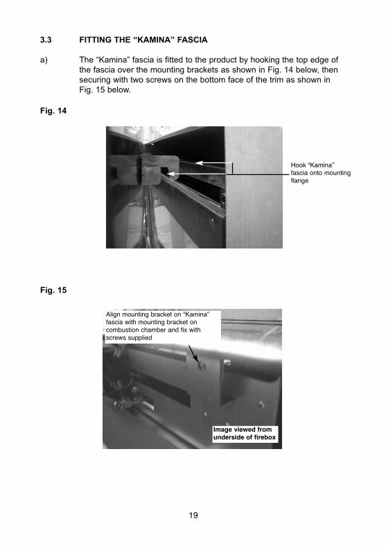
3.3 FITTING THE “KAMINA” FASCIA
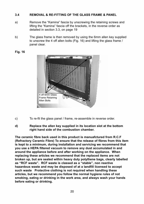
a) The “Kamina” fascia is fitted to the product by hooking the top edge ofthe fascia over the mounting brackets as shown in Fig. 14 below, thensecuring with two screws on the bottom face of the trim as shown inFig. 15 below.
Fig. 14
Fig. 15
Align mounting bracket on “Kamina”fascia with mounting bracket oncombustion chamber and fix withscrews supplied
Image viewed fromunderside of firebox
Hook “Kamina”fascia onto mountingflange
19
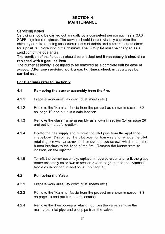
3.4 REMOVAL & RE-FITTING OF THE GLASS FRAME & PANEL
a) Remove the “Kamina” fascia by unscrewing the retaining screws andlifting the “Kamina” fascia off the brackets, in the reverse order asdetailed in section 3.3, on page 19
b) The glass frame is then removed by using the 6mm allen key suppliedto unscrew the 4 off allen bolts (Fig. 16) and lifting the glass frame /panel clear.
Fig. 16
c) To re-fit the glass panel / frame, re-assemble in reverse order.
d) Replace the allen key supplied in its location slot at the bottomright hand side of the combustion chamber.
The ceramic fibre back used in this product is manuafctured from R.C.F(Refractory Ceramic Fibre) To ensure that the release of fibres from this itemis kept to a minimum, during installation and servicing we recommend thatyou use a HEPA filtered vacuum to remove any dust accumulated in andaround the appliance before and after working on the appliance. Whenreplacing these articles we recommend that the replaced items are notbroken up, but are sealed within heavy duty polythene bags, clearly labelledas “RCF waste”. RCF waste is classed as a “stable”, non reactivehazardous waste and may be disposed of at a landfill licensed to acceptsuch waste Protective clothing is not required when handling thesearticles, but we recommend you follow the normal hygiene rules of notsmoking, eating or drinking in the work area, and always wash your handsbefore eating or drinking.
20
4 off 6mm GlassFrame RetainingAllen Bolts
SECTION 4MAINTENANCE
Servicing NotesServicing should be carried out annually by a competent person such as a GASSAFE registered engineer. The service should include visually checking thechimney and fire opening for accumulations of debris and a smoke test to checkfor a positive up-draught in the chimney. The ODS pilot must be changed as acondition of the guarantee.The condition of the fibreback should be checked and if necessary it should bereplaced with a genuine item.The burner assembly is designed to be removed as a complete unit for ease ofaccess. After any servicing work a gas tightness check must always becarried out.
For Diagrams refer to Section 2
4.1 Removing the burner assembly from the fire.
4.1.1 Prepare work area (lay down dust sheets etc.)
4.1.2 Remove the “Kamina” fascia from the product as shown in section 3.3on page 19 and put it in a safe location.
4.1.3 Remove the glass frame assembly as shown in section 3.4 on page 20and put it in a safe location.
4.1.4 Isolate the gas supply and remove the inlet pipe from the applianceinlet elbow. Disconnect the pilot pipe, ignition wire and remove the pilotretaining screws. Unscrew and remove the two screws which retain theburner brackets to the base of the fire. Remove the burner from itslocation, on the injector
4.1.5 To refit the burner assembly, replace in reverse order and re-fit the glassframe assembly as shown in section 3.4 on page 20 and the “Kamina”fascia as described in section 3.3 on page 19.
4.2 Removing the Valve
4.2.1 Prepare work area (lay down dust sheets etc.)
4.2.2 Remove the “Kamina” fascia from the product as shown in section 3.3on page 19 and put it in a safe location.
4.2.4 Remove the thermocouple retaing nut from the valve, remove themain pipe, inlet pipe and pilot pipe from the valve.
21
4.2.5 Remove the valve retaining screws and remove the valve. Re-assemblein reverse order and carry out a gas tightness test. Re-fit the “Kamina”fascia as described in section 3.3 on page 19.
4.3 Removing the Pilot Assembly.
Note : Because this appliance is fitted with an atmosphere sensing ‘Oxy-Pilot’ it is not possible to replace the thermocouple separately, because thethermocouple position is factory set to a tight tolerance. Any replacement ofparts on the pilot requires a complete new pilot assembly.
4.3.1 Prepare work area (lay down dust sheets etc.)
4.3.2 Remove the “Kamina” fascia from the product as shown in section 3.3on page 19 and put it in a safe location.
4.3.3 Remove the glass frame assembly as shown in section 3.4 on page 20and put it in a safe location.
4.3.4 Loosen the pilot nut and remove the two screws retaining the pilotassembly. Unscrew the thermocouple from the gas valve.
4.3.4 Re-assemble in reverse order and carry out a gas tightness test andre-fit the glass frame assembly as shown in section 3.4 on page 20 andthe “Kamina” fascia as described in section 3.3 on page 19.
4.4 Replacing the Batteries (Within the Radio Frequency Receiver)
4.4.1 Prepare work area (lay down dust sheets etc.)
4.4.2 Remove the “Kamina” fascia from the product as shown in section 3.3on page 19 and put it in a safe location.
4.4.3 The RF receiver is located in the centre of the product, below the burnerassembly. Unscrew the retaining screw and remove the RF receiver.Slide the battery cover off and replace the batteries as necessary.
4.4.4 Replace the “Kamina” fascia as described in section 3.3 on page 19.
4.4.5 Replace in reverse order and check correct operation of the appliance.
NB The handset uses one LR61 (9v) and should be replaced byremoving the cover on the rear of the handset.
ENSURE THE BATTERIES ARE CONNECTED TO THE CORRECT POLARITYPOSITVE (+), NEGATIVE (-)
22
PARTS SHORTLIST
Replacement of any other parts must be carried out by a competent person suchas a GAS SAFE registered gas installer. The part numbers of the replaceableparts are as follows, these are available from BFM Europe, contact details asshown below.
This appliance must only be used with the fascia supplied.
Gas Control Valve B-92200Handset B-159250Receiver B-153140Ignition Lead B-50380Thermocouple Interupter B-93310On / Off Switch & Supply Wires B-93320Ribbed Fibre Back B-92030Glass Panel B-92020
Due to our policy of continual improvement and development the exactaccuracy of illustrations and descriptions contained in this book cannot beguaranteed
Part No. B-148240Issue 2
BFM Europe Ltd.Trentham LakesStoke-on-TrentStaffordshireST4 4TJ
www.bfm-europe.com
Telephone - General Enquiries : (01782) 339000Telephone - Service : (0844) 7700169