Embed Size (px)
Citation preview
Architecture Steel Stahl Acier 21
21
Steel Stahl AcierArchitecture
ECCSCECMEKS
European Convention for Constructional SteelworkConvention Européenne de la Construction MétalliqueEuropäische Konvention für Stahlbau
Swiss ReOffice building
Tour de bureauxde la Swiss Re
Verwaltungs-gebäude Swiss Re
Architecture Steel Stahl Acier 21
ECCS N° 91-21ISBN 92-9147-000-80
All rights reserved.No part of this document may be reproduced withoutthe written authorisation of ECCS.
Tous droits réservés.Aucune partie de ce document ne peut être reproduitesans autorisation écrite de la CECM.
Alle Rechte vorbehalten.Kein Teil dieser Publikation darf ohne schriftlicheZustimmung der EKS in jedwelcher Form vervielfältigtwerden.
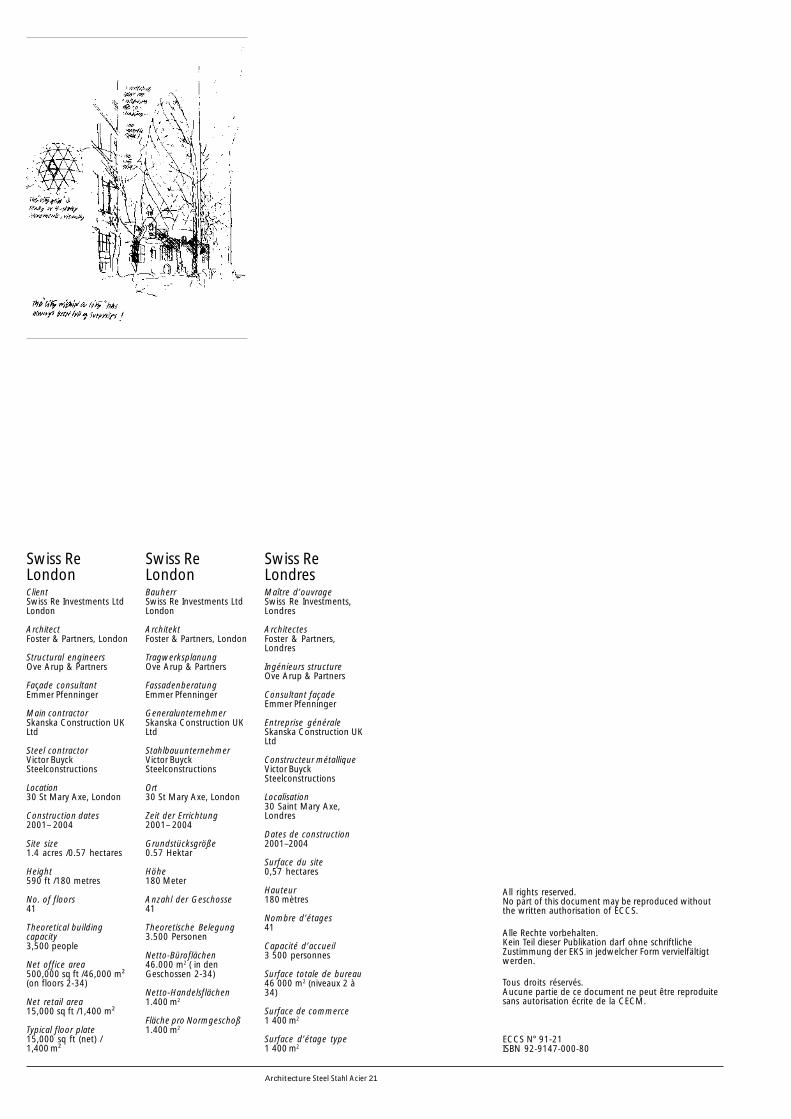
Swiss ReLondonClientSwiss Re Investments LtdLondon
ArchitectFoster & Partners, London
Structural engineersOve Arup & Partners
Façade consultantEmmer Pfenninger
Main contractorSkanska Construction UKLtd
Steel contractorVictor BuyckSteelconstructions
Location30 St Mary Axe, London
Construction dates2001– 2004
Site size1.4 acres /0.57 hectares
Height590 ft /180 metres
No. of floors41
Theoretical buildingcapacity3,500 people
Net office area500,000 sq ft /46,000 m²(on floors 2-34)
Net retail area15,000 sq ft /1,400 m²
Typical floor plate15,000 sq ft (net) /1,400 m²
Swiss ReLondresMaître d’ouvrageSwiss Re Investments,Londres
ArchitectesFoster & Partners,Londres
Ingénieurs structureOve Arup & Partners
Consultant façadeEmmer Pfenninger
Entreprise généraleSkanska Construction UKLtd
Constructeur métalliqueVictor BuyckSteelconstructions
Localisation30 Saint Mary Axe,Londres
Dates de construction2001–2004
Surface du site0,57 hectares
Hauteur180 mètres
Nombre d’étages41
Capacité d’accueil3 500 personnes
Surface totale de bureau46 000 m2 (niveaux 2 à34)
Surface de commerce1 400 m2
Surface d’étage type1 400 m2
Swiss ReLondonBauherrSwiss Re Investments LtdLondon
ArchitektFoster & Partners, London
TragwerksplanungOve Arup & Partners
FassadenberatungEmmer Pfenninger
GeneralunternehmerSkanska Construction UKLtd
StahlbauunternehmerVictor BuyckSteelconstructions
Ort30 St Mary Axe, London
Zeit der Errichtung2001– 2004
Grundstücksgröße0.57 Hektar
Höhe180 Meter
Anzahl der Geschosse41
Theoretische Belegung3.500 Personen
Netto-Büroflächen46.000 m2 ( in denGeschossen 2-34)
Netto-Handelsflächen1.400 m2
Fläche pro Normgeschoß1.400 m2
1Architecture Steel Stahl Acier 21
Introduction
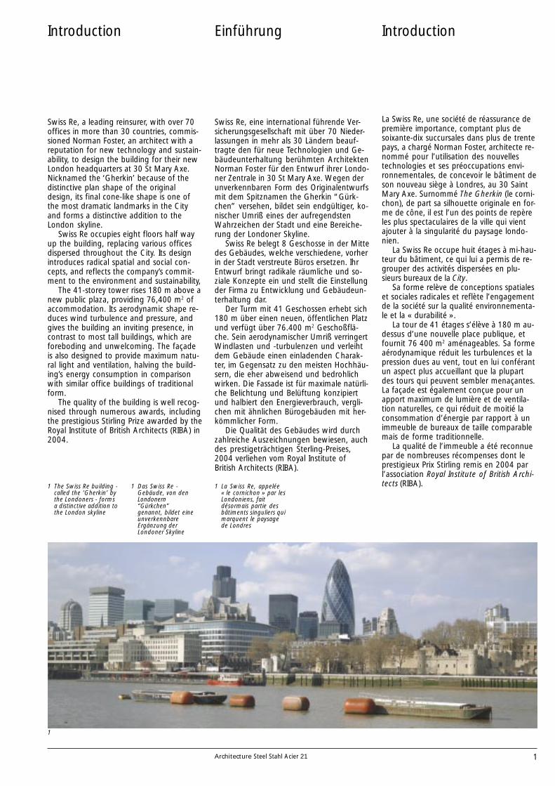
Swiss Re, a leading reinsurer, with over 70offices in more than 30 countries, commis-sioned Norman Foster, an architect with areputation for new technology and sustain-ability, to design the building for their newLondon headquarters at 30 St Mary Axe.Nicknamed the ‘Gherkin’ because of thedistinctive plan shape of the originaldesign, its final cone-like shape is one ofthe most dramatic landmarks in the Cityand forms a distinctive addition to theLondon skyline.
Swiss Re occupies eight floors half wayup the building, replacing various officesdispersed throughout the City. Its designintroduces radical spatial and social con-cepts, and reflects the company’s commit-ment to the environment and sustainability,
The 41-storey tower rises 180 m above anew public plaza, providing 76,400 m2 ofaccommodation. Its aerodynamic shape re-duces wind turbulence and pressure, andgives the building an inviting presence, incontrast to most tall buildings, which areforeboding and unwelcoming. The façadeis also designed to provide maximum natu-ral light and ventilation, halving the build-ing’s energy consumption in comparisonwith similar office buildings of traditionalform.
The quality of the building is well recog-nised through numerous awards, includingthe prestigious Stirling Prize awarded by theRoyal Institute of British Architects (RIBA) in2004.
1
1 The Swiss Re building -called the ‘Gherkin’ bythe Londoners - formsa distinctive addition tothe London skyline
La Swiss Re, une société de réassurance depremière importance, comptant plus desoixante-dix succursales dans plus de trentepays, a chargé Norman Foster, architecte re-nommé pour l’utilisation des nouvellestechnologies et ses préoccupations envi-ronnementales, de concevoir le bâtiment deson nouveau siège à Londres, au 30 SaintMary Axe. Surnommé The Gherkin (le corni-chon), de part sa silhouette originale en for-me de cône, il est l’un des points de repèreles plus spectaculaires de la ville qui vientajouter à la singularité du paysage londo-nien.
La Swiss Re occupe huit étages à mi-hau-teur du bâtiment, ce qui lui a permis de re-grouper des activités dispersées en plu-sieurs bureaux de la City.
Sa forme relève de conceptions spatialeset sociales radicales et reflète l’engagementde la société sur la qualité environnementa-le et la « durabilité ».
La tour de 41 étages s’élève à 180 m au-dessus d’une nouvelle place publique, etfournit 76 400 m2 aménageables. Sa formeaérodynamique réduit les turbulences et lapression dues au vent, tout en lui conférantun aspect plus accueillant que la plupartdes tours qui peuvent sembler menaçantes.La façade est également conçue pour unapport maximum de lumière et de ventila-tion naturelles, ce qui réduit de moitié laconsommation d’énergie par rapport à unimmeuble de bureaux de taille comparablemais de forme traditionnelle.
La qualité de l’immeuble a été reconnuepar de nombreuses récompenses dont leprestigieux Prix Stirling remis en 2004 parl’association Royal Institute of British Archi-tects (RIBA).
Introduction
1 La Swiss Re, appelée« le cornichon » par lesLondoniens, faitdésormais partie desbâtiments singuliers quimarquent le paysagede Londres
Swiss Re, eine international führende Ver-sicherungsgesellschaft mit über 70 Nieder-lassungen in mehr als 30 Ländern beauf-tragte den für neue Technologien und Ge-bäudeunterhaltung berühmten ArchitektenNorman Foster für den Entwurf ihrer Londo-ner Zentrale in 30 St Mary Axe. Wegen derunverkennbaren Form des Originalentwurfsmit dem Spitznamen the Gherkin “Gürk-chen” versehen, bildet sein endgültiger, ko-nischer Umriß eines der aufregendstenWahrzeichen der Stadt und eine Bereiche-rung der Londoner Skyline.
Swiss Re belegt 8 Geschosse in der Mittedes Gebäudes, welche verschiedene, vorherin der Stadt verstreute Büros ersetzen. IhrEntwurf bringt radikale räumliche und so-ziale Konzepte ein und stellt die Einstellungder Firma zu Entwicklung und Gebäudeun-terhaltung dar.
Der Turm mit 41 Geschossen erhebt sich180 m über einen neuen, öffentlichen Platzund verfügt über 76.400 m2 Geschoßflä-che. Sein aerodynamischer Umriß verringertWindlasten und -turbulenzen und verleihtdem Gebäude einen einladenden Charak-ter, im Gegensatz zu den meisten Hochhäu-sern, die eher abweisend und bedrohlichwirken. Die Fassade ist für maximale natürli-che Belichtung und Belüftung konzipiertund halbiert den Energieverbrauch, vergli-chen mit ähnlichen Bürogebäuden mit her-kömmlicher Form.
Die Qualität des Gebäudes wird durchzahlreiche Auszeichnungen bewiesen, auchdes prestigeträchtigen Sterling-Preises,2004 verliehen vom Royal Institute ofBritish Architects (RIBA).
Einführung
1 Das Swiss Re -Gebäude, von denLondonern“Gürkchen”genannt, bildet eineunverkennbareErgänzung derLondoner Skyline

2 Architecture Steel Stahl Acier 21
The site and planning
In 1992 the Baltic Exchange, the headquar-ters building of a global shipping companyand the last Edwardian trading floor in theCity of London, was severely damaged by aterrorist bomb. The extent of the damagewas so great that the planners had to aban-don their initial requirement for the rede-velopment to include restoration of the his-toric façade of the Exchange onto St MaryAxe.
A further consideration for the plannerswas that a number of banks and financialinstitutions were moving out of the City totake advantage of modern buildings withlarge floor plates. Such forms had not beenallowed within the City by the planners,forcing firms either to disperse their staffacross many sites or move into other partsof London, notably Docklands, where highquality offices were plentiful. When thiswas realised the City planners eased therestrictions.
2
2 Site plan
Site et planification
En 1992, le Baltic Exchange, siège d’une so-ciété internationale de transport et dernierparquet boursier de la City datant de l’épo-que édouardienne, a été sérieusement en-dommagé par une bombe lors d’un atten-tat terroriste. L’importance des dommagesétait telle que les responsables de la planifi-cation ont dû abandonner leur projet initialde rénovation qui comprenait la restaura-tion de la façade historique de la Bourse surSaint Mary Axe.
En outre, ils prirent en considération lefait que de nombreuses banques et institu-tions financières quittaient la City, pousséespar le besoin d’immeubles modernes avecde grands plateaux. Ce type d’immeubleétait jusqu’alors interdit dans la City, obli-geant les sociétés soit à disperser leurséquipes en plusieurs lieux, soit à déména-ger dans d’autres parties de Londres, enparticulier celle des Docklands où les im-meubles de bureaux de qualité étaientnombreux. Prenant conscience de ce phé-nomène, les responsables de la planifica-tion ont assoupli les contraintes s’appli-quant aux immeubles de la City.
2 Plan du site
Standort und Planung
Im Jahr 1992 wurde die Baltic Exchange,der Hauptsitz einer internationalen Schif-fahrtsgesellschaft und der letzte Handels-platz aus Edwardianischer Zeit durch einenterroristischen Anschlag schwer beschädigt.Das Ausmaß der Schäden war so hoch, daßdie Planer ihre ursprüngliche Vorstellungvon einem Wiederaufbau mit Rekonstrukti-on der historischen Fassade auf der St MaryAxe revidieren mußten.
Weiterhin mußten die Planer berücksich-tigen, daß mehrere Banken und Finanzfir-men die City verließen, um moderne Ge-bäude mit großen Geschoßebenen zu be-ziehen. Derlei Formen sind in der City nichtzugelassen, sodaß die Firmen gezwungenwaren, ihr Personal aufzuteilen, oder in an-dere Teile Londons, besonders in die Dock-lands, wo große Büroflächen mit hoherQualität zur Verfügung standen, umzusie-deln. Als dies geschehen war, haben dieStadtplaner die Restriktionen abge-schwächt.
2 Lageplan
3Architecture Steel Stahl Acier 21
3
4
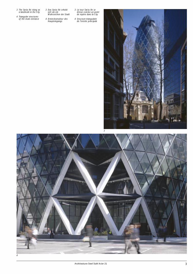
3 The Swiss Re rising asa landmark in the City
4 Triangular structuresof the main entrance
3 La tour Swiss Re sedresse comme un pointde repère dans la City
4 Structure triangulairede l’entrée principale
3 Das Swiss Re erhebtsich als einWahrzeichen der Stadt
4 Dreiecksstruktur desHaupteingangs

4 Architecture Steel Stahl Acier 21
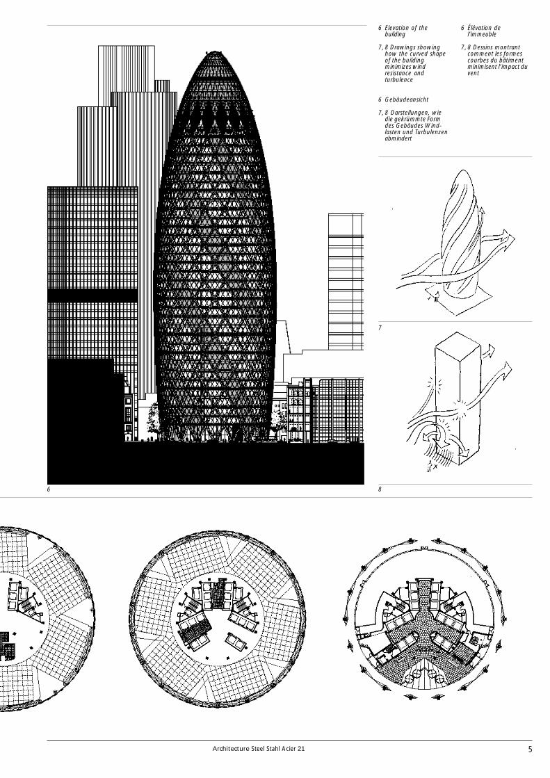
In the dense urban fabric of the City of Lon-don with its relatively narrow streets, the41-storey tower retains a surprisingly dis-crete presence. In contrast to other tallbuildings it barely imposes itself on visitorsin the immediate vicinity until they are di-rectly underneath it. The tower widens as itrises from the ground, then tapers towardsits apex, affording a less bulky appearancethan a conventional rectangular form. Theglass façade further emphasises the trans-parency with large plate glass windows atground level presenting an open aspect tothe visitor.
The building is circular in plan and meas-ures 56 m in diameter at its widest point,reducing to 49 m at ground level. This aero-dynamic form was developed on the basisof wind tunnel tests, and helps reduce un-pleasant wind turbulence associated withso many tall buildings. Reflections are alsoreduced and transparency is improved.
The majority of the building provides of-fice accommodation, divided into areas of16 m x 11 m and affording excellent viewsthroughout. The lower floors include publicshopping areas and at the very top there isa restaurant offering panoramic viewsacross the city. The traditional undergroundcar park is replaced by spaces for 170 cyclesand motorbikes, with changing rooms andshowers.
Form
5
5 The floor plans fromthe top to the entrancefloor
Forme
Dans le tissu urbain dense de la City de Lon-dres, avec ses rues relativement étroites, ladiscrétion de la tour de 41 étages a de quoisurprendre. Contrairement à d’autres tours,elle s’impose à peine aux visiteurs alentour,tant qu’ils ne sont pas à ses pieds. Elles’élargit en s’éloignant du sol, puis s’effilevers son sommet, ce qui lui donne une ap-parence moins massive que la forme rectan-gulaire conventionnelle. La façade de verrecontribue à cette discrétion avec ses gran-des surfaces vitrées au niveau du rez-de-chaussée qui donnent une impressiond’ouverture au visiteur.
Le plan de la tour est circulaire, son dia-mètre atteint 56 m à l’étage le plus grand etse réduit jusqu’à 49 m au rez-de-chaussée.Cette forme aérodynamique a été mise aupoint au cours des essais en soufflerie, ellepermet de réduire les désagréments dusaux turbulences du vent ressenties dans denombreuses constructions élevées. Elle di-minue également les reflets et améliore latransparence. La tour est principalementéquipée pour des plateaux de bureau de16 m x 11 m, jouissant tous d’une excellen-te vue sur l’extérieur. Les étages inférieurscomprennent un centre commercial et lesommet abrite un restaurant avec une vuepanoramique sur la ville. Le sous-sol habi-tuellement dédié au parking automobile,est une surface réservée aux bicyclettes etmotos – il peut en accueillir 170 –, équipéede vestiaires et de douches.
5 Plans de différentsniveaux, du sommet aurez-de-chaussée
Form
Im engen Londoner Stadtbild, mit seinenrelativ schmalen Straßen, bleibt der 41-ge-schossige Turm erstaunlich unauffällig. ImUnterschied zu anderen, höheren Gebäu-den stellt er sich selbst für Besucher in di-rekter Nachbarschaft erst dar, wenn sie sichdirekt darunter befinden. Der Turm verbrei-tert sich mit steigender Höhe und verjüngtsich dann zur Spitze und vermittelt so eineweniger massive Erscheinung als eine her-kömmliche, rechteckige Form. Die Glasfas-sade betont überdies die Transparenz mitgroßen Glasfenstern und vermittelt im Erd-geschoß dem Besucher einen offenen Ein-druck.
Das Gebäude ist im Grundriß kreisför-mig und hat an der breitesten Stelle einenDurchmesser von 56 m, der sich im Erdge-schoß auf 49 m verringert. Diese aerodyna-mische Form wurde aufgrund von Windka-nalversuchen entwickelt und reduziert un-angenehme Turbulenzen, wie sie bei so vie-len Hochhäusern auftreten. Auch werdenso Reflexionen vermieden und Transparenzgeschaffen.
Der größte Teil des Gebäudes bestehtaus Büroflächen, die in Zonen von 16 x 11m geteilt sind und die sehr gute Durchblik-ke ermöglichen. Die unteren Geschosse be-inhalten öffentliche Einkaufsflächen und inder Spitze ist ein Restaurant untergebracht,das einen Panoramaausblick über die Stadtermöglicht. Die traditionelle Tiefgaragewurde durch Flächen für 170 Fahr- und Mo-torräder, mit Duschen und Umkleideräu-men ersetzt.
5 Die Grundrisse von derSpitze bis zumErdgeschoß
5Architecture Steel Stahl Acier 21
8
6
7
8
6 Elevation of thebuilding
7, 8 Drawings showinghow the curved shapeof the buildingminimizes windresistance andturbulence
6 Élévation del’immeuble
7, 8 Dessins montrantcomment les formescourbes du bâtimentminimisent l’impact duvent
6 Gebäudeansicht
7, 8 Darstellungen, wiedie gekrümmte Formdes Gebäudes Wind-lasten und Turbulenzenabmindert
6 Architecture Steel Stahl Acier 21
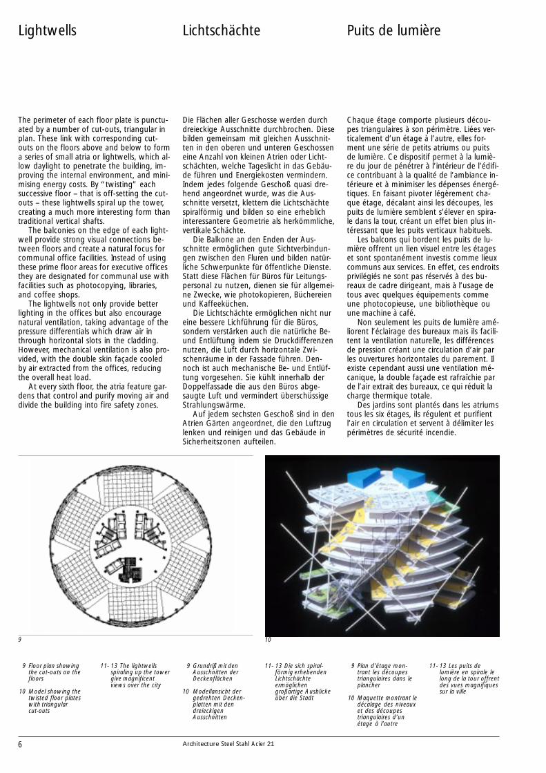
The perimeter of each floor plate is punctu-ated by a number of cut-outs, triangular inplan. These link with corresponding cut-outs on the floors above and below to forma series of small atria or lightwells, which al-low daylight to penetrate the building, im-proving the internal environment, and mini-mising energy costs. By “twisting” eachsuccessive floor – that is off-setting the cut-outs – these lightwells spiral up the tower,creating a much more interesting form thantraditional vertical shafts.
The balconies on the edge of each light-well provide strong visual connections be-tween floors and create a natural focus forcommunal office facilities. Instead of usingthese prime floor areas for executive officesthey are designated for communal use withfacilities such as photocopying, libraries,and coffee shops.
The lightwells not only provide betterlighting in the offices but also encouragenatural ventilation, taking advantage of thepressure differentials which draw air inthrough horizontal slots in the cladding.However, mechanical ventilation is also pro-vided, with the double skin façade cooledby air extracted from the offices, reducingthe overall heat load.
At every sixth floor, the atria feature gar-dens that control and purify moving air anddivide the building into fire safety zones.
Lightwells
9 10
9 Floor plan showingthe cut-outs on thefloors
10 Model showing thetwisted floor plateswith triangularcut-outs
11- 13 The lightwellsspiraling up the towergive magnificentviews over the city
Puits de lumière
Chaque étage comporte plusieurs décou-pes triangulaires à son périmètre. Liées ver-ticalement d’un étage à l’autre, elles for-ment une série de petits atriums ou puitsde lumière. Ce dispositif permet à la lumiè-re du jour de pénétrer à l’intérieur de l’édifi-ce contribuant à la qualité de l’ambiance in-térieure et à minimiser les dépenses énergé-tiques. En faisant pivoter légèrement cha-que étage, décalant ainsi les découpes, lespuits de lumière semblent s’élever en spira-le dans la tour, créant un effet bien plus in-téressant que les puits verticaux habituels.
Les balcons qui bordent les puits de lu-mière offrent un lien visuel entre les étageset sont spontanément investis comme lieuxcommuns aux services. En effet, ces endroitsprivilégiés ne sont pas réservés à des bu-reaux de cadre dirigeant, mais à l’usage detous avec quelques équipements commeune photocopieuse, une bibliothèque ouune machine à café.
Non seulement les puits de lumière amé-liorent l’éclairage des bureaux mais ils facili-tent la ventilation naturelle, les différencesde pression créant une circulation d’air parles ouvertures horizontales du parement. Ilexiste cependant aussi une ventilation mé-canique, la double façade est rafraîchie parde l’air extrait des bureaux, ce qui réduit lacharge thermique totale.
Des jardins sont plantés dans les atriumstous les six étages, ils régulent et purifientl’air en circulation et servent à délimiter lespérimètres de sécurité incendie.
9 Plan d’étage mon-trant les découpestriangulaires dans leplancher
10 Maquette montrant ledécalage des niveauxet des découpestriangulaires d’unétage à l’autre
11- 13 Les puits delumière en spirale lelong de la tour offrentdes vues magnifiquessur la ville
Die Flächen aller Geschosse werden durchdreieckige Ausschnitte durchbrochen. Diesebilden gemeinsam mit gleichen Ausschnit-ten in den oberen und unteren Geschosseneine Anzahl von kleinen Atrien oder Licht-schächten, welche Tageslicht in das Gebäu-de führen und Energiekosten vermindern.Indem jedes folgende Geschoß quasi dre-hend angeordnet wurde, was die Aus-schnitte versetzt, klettern die Lichtschächtespiralförmig und bilden so eine erheblichinteressantere Geometrie als herkömmliche,vertikale Schächte.
Die Balkone an den Enden der Aus-schnitte ermöglichen gute Sichtverbindun-gen zwischen den Fluren und bilden natür-liche Schwerpunkte für öffentliche Dienste.Statt diese Flächen für Büros für Leitungs-personal zu nutzen, dienen sie für allgemei-ne Zwecke, wie photokopieren, Büchereienund Kaffeeküchen.
Die Lichtschächte ermöglichen nicht nureine bessere Lichführung für die Büros,sondern verstärken auch die natürliche Be-und Entlüftung indem sie Druckdifferenzennutzen, die Luft durch horizontale Zwi-schenräume in der Fassade führen. Den-noch ist auch mechanische Be- und Entlüf-tung vorgesehen. Sie kühlt innerhalb derDoppelfassade die aus den Büros abge-saugte Luft und vermindert überschüssigeStrahlungswärme.
Auf jedem sechsten Geschoß sind in denAtrien Gärten angeordnet, die den Luftzuglenken und reinigen und das Gebäude inSicherheitszonen aufteilen.
Lichtschächte
9 Grundriß mit denAusschnitten derDeckenflächen
10 Modellansicht dergedrehten Decken-platten mit dendreieckigenAusschnitten
11- 13 Die sich spiral-förmig erhebendenLichtschächteermöglichengroßartige Ausblickeüber die Stadt

7Architecture Steel Stahl Acier 21
11
12 13
8 Architecture Steel Stahl Acier 21
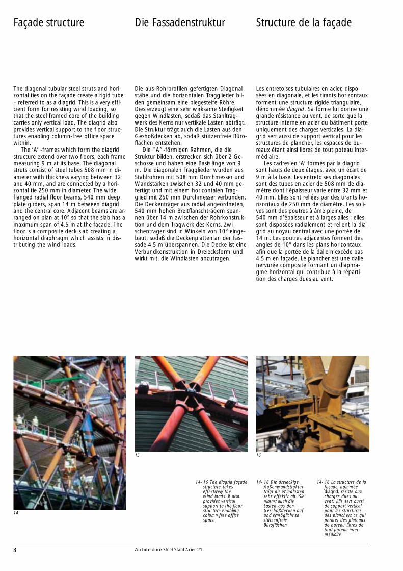
The diagonal tubular steel struts and hori-zontal ties on the façade create a rigid tube– referred to as a diagrid. This is a very effi-cient form for resisting wind loading, sothat the steel framed core of the buildingcarries only vertical load. The diagrid alsoprovides vertical support to the floor struc-tures enabling column-free office spacewithin.
The ‘A’ -frames which form the diagridstructure extend over two floors, each framemeasuring 9 m at its base. The diagonalstruts consist of steel tubes 508 mm in di-ameter with thickness varying between 32and 40 mm, and are connected by a hori-zontal tie 250 mm in diameter. The wideflanged radial floor beams, 540 mm deepplate girders, span 14 m between diagridand the central core. Adjacent beams are ar-ranged on plan at 10º so that the slab has amaximum span of 4.5 m at the façade. Thefloor is a composite deck slab creating ahorizontal diaphragm which assists in dis-tributing the wind loads.
Façade structure
14
15 16
14- 16 The diagrid façadestructure takeseffectively thewind loads. It alsoprovides verticalsupport to the floorstructure enablingcolumn free officespace
Structure de la façade
Les entretoises tubulaires en acier, dispo-sées en diagonale, et les tirants horizontauxforment une structure rigide triangulaire,dénommée diagrid. Sa forme lui donne unegrande résistance au vent, de sorte que lastructure interne en acier du bâtiment porteuniquement des charges verticales. La dia-grid sert aussi de support vertical pour lesstructures de plancher, les espaces de bu-reaux étant ainsi libres de tout poteau inter-médiaire.
Les cadres en ‘A’ formés par la diagridsont hauts de deux étages, avec un écart de9 m à la base. Les entretoises diagonalessont des tubes en acier de 508 mm de dia-mètre dont l’épaisseur varie entre 32 mm et40 mm. Elles sont reliées par des tirants ho-rizontaux de 250 mm de diamètre. Les soli-ves sont des poutres à âme pleine, de540 mm d’épaisseur et à larges ailes ; ellessont disposées radialement et relient la dia-grid au noyau central avec une portée de14 m. Les poutres adjacentes forment desangles de 10º dans les plans horizontauxafin que la portée de la dalle n’excède pas4,5 m en façade. Le plancher est une dallenervurée composite formant un diaphra-gme horizontal qui contribue à la réparti-tion des charges dues au vent.
14- 16 La structure de lafaçade, nomméediagrid, résiste auxcharges dues auvent. Elle sert ausside support verticalpour les structuresdes planchers ce quipermet des plateauxde bureau libres detout poteau inter-médiaire
Die Fassadenstruktur
Die aus Rohrprofilen gefertigten Diagonal-stäbe und die horizontalen Tragglieder bil-den gemeinsam eine biegesteife Röhre.Dies erzeugt eine sehr wirksame Steifigkeitgegen Windlasten, sodaß das Stahltrag-werk des Kerns nur vertikale Lasten abträgt.Die Struktur trägt auch die Lasten aus denGeshoßdecken ab, sodaß stützenfreie Büro-flächen entstehen.
Die “A”-förmigen Rahmen, die dieStruktur bilden, erstrecken sich über 2 Ge-schosse und haben eine Basislänge von 9m. Die diagonalen Tragglieder wurden ausStahlrohren mit 508 mm Durchmesser undWandstärken zwischen 32 und 40 mm ge-fertigt und mit einem horizontalen Trag-glied mit 250 mm Durchmesser verbunden.Die Deckenträger aus radial angeordneten,540 mm hohen Breitflanschträgern span-nen über 14 m zwischen der Rohrkonstruk-tion und dem Tragwerk des Kerns. Zwi-schenträger sind in Winkeln von 10° einge-baut, sodaß die Deckenplatten an der Fas-sade 4,5 m überspannen. Die Decke ist eineVerbundkonstruktion in Dreiecksform undwirkt mit, die Windlasten abzutragen.
14- 16 Die dreieckigeAußenwandstrukturträgt die Windlastensehr effektiv ab. Sienimmt auch dieLasten aus denGeschoßdecken aufund ermöglicht sostützenfreieBüroflächen
9Architecture Steel Stahl Acier 21
17
18
17, 18 Axonométrie1 Appuis diagonaux2 Nœuds3 Tirants4 Poutre de dalle avec
appui glissant5 Barres filetées pour le
réglage de ladilatation radiale
6 Plaques pour lafixation tangentielledes poutres
7 Poutre de dallesecondaire
8 Supports pour levitrage
17, 18 Axonometrie derKnoten
1 Diagonalstäbe2 Knoten3 Zugstab4 Deckenträger mit
gleitendem Anschluß5 Gewindestangen für
die Justierung vonLängenänderungen
6 Bleche für dentangentialen Anschlußder Träger
7 SekundäreDeckenträger
8 Tragelemente für dieVerglasung
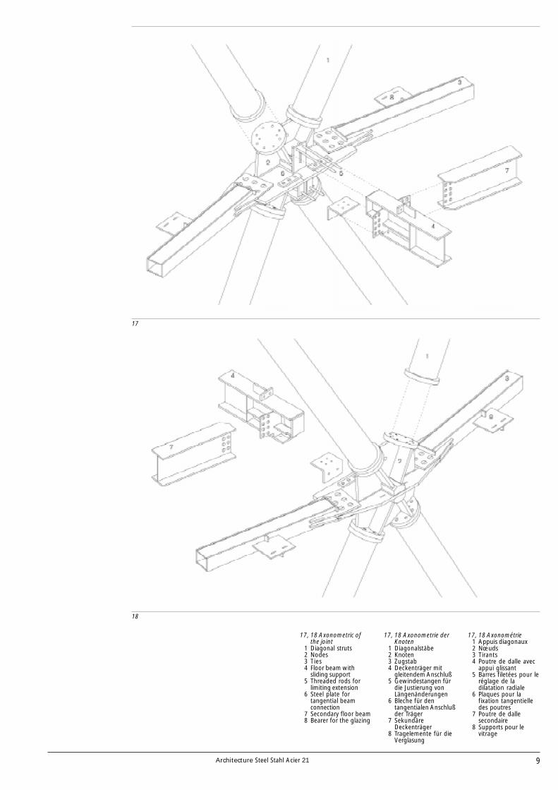
17, 18 Axonometric ofthe joint
1 Diagonal struts2 Nodes3 Ties4 Floor beam with
sliding support5 Threaded rods for
limiting extension6 Steel plate for
tangential beamconnection
7 Secondary floor beam8 Bearer for the glazing
10 Architecture Steel Stahl Acier 21
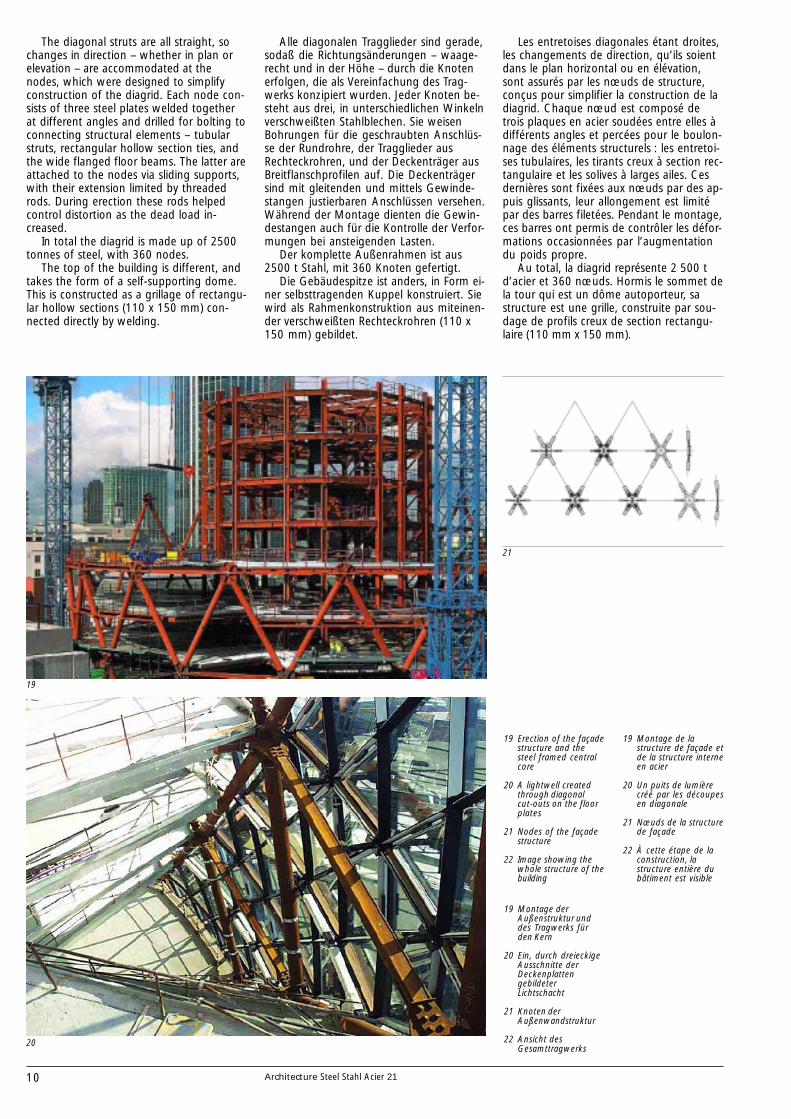
The diagonal struts are all straight, sochanges in direction – whether in plan orelevation – are accommodated at thenodes, which were designed to simplifyconstruction of the diagrid. Each node con-sists of three steel plates welded togetherat different angles and drilled for bolting toconnecting structural elements – tubularstruts, rectangular hollow section ties, andthe wide flanged floor beams. The latter areattached to the nodes via sliding supports,with their extension limited by threadedrods. During erection these rods helpedcontrol distortion as the dead load in-creased.
In total the diagrid is made up of 2500tonnes of steel, with 360 nodes.
The top of the building is different, andtakes the form of a self-supporting dome.This is constructed as a grillage of rectangu-lar hollow sections (110 x 150 mm) con-nected directly by welding.
19
20
21
19 Erection of the façadestructure and thesteel framed centralcore
20 A lightwell createdthrough diagonalcut-outs on the floorplates
21 Nodes of the façadestructure
22 Image showing thewhole structure of thebuilding
Les entretoises diagonales étant droites,les changements de direction, qu’ils soientdans le plan horizontal ou en élévation,sont assurés par les nœuds de structure,conçus pour simplifier la construction de ladiagrid. Chaque nœud est composé detrois plaques en acier soudées entre elles àdifférents angles et percées pour le boulon-nage des éléments structurels : les entretoi-ses tubulaires, les tirants creux à section rec-tangulaire et les solives à larges ailes. Cesdernières sont fixées aux nœuds par des ap-puis glissants, leur allongement est limitépar des barres filetées. Pendant le montage,ces barres ont permis de contrôler les défor-mations occasionnées par l’augmentationdu poids propre.
Au total, la diagrid représente 2 500 td’acier et 360 nœuds. Hormis le sommet dela tour qui est un dôme autoporteur, sastructure est une grille, construite par sou-dage de profils creux de section rectangu-laire (110 mm x 150 mm).
19 Montage de lastructure de façade etde la structure interneen acier
20 Un puits de lumièrecréé par les découpesen diagonale
21 Nœuds de la structurede façade
22 À cette étape de laconstruction, lastructure entière dubâtiment est visible
Alle diagonalen Tragglieder sind gerade,sodaß die Richtungsänderungen – waage-recht und in der Höhe – durch die Knotenerfolgen, die als Vereinfachung des Trag-werks konzipiert wurden. Jeder Knoten be-steht aus drei, in unterschiedlichen Winkelnverschweißten Stahlblechen. Sie weisenBohrungen für die geschraubten Anschlüs-se der Rundrohre, der Tragglieder ausRechteckrohren, und der Deckenträger ausBreitflanschprofilen auf. Die Deckenträgersind mit gleitenden und mittels Gewinde-stangen justierbaren Anschlüssen versehen.Während der Montage dienten die Gewin-destangen auch für die Kontrolle der Verfor-mungen bei ansteigenden Lasten.
Der komplette Außenrahmen ist aus2500 t Stahl, mit 360 Knoten gefertigt.
Die Gebäudespitze ist anders, in Form ei-ner selbsttragenden Kuppel konstruiert. Siewird als Rahmenkonstruktion aus miteinen-der verschweißten Rechteckrohren (110 x150 mm) gebildet.
19 Montage derAußenstruktur unddes Tragwerks fürden Kern
20 Ein, durch dreieckigeAusschnitte derDeckenplattengebildeterLichtschacht
21 Knoten derAußenwandstruktur
22 Ansicht desGesamttragwerks

11Architecture Steel Stahl Acier 21
22

12 Architecture Steel Stahl Acier 21
The façade is fully glazed with approximate-ly 5,500 triangular or diamond-shapedglass panels, which vary in size at each level.It uses double façade construction consist-ing of a double-glazed units on the exteriorand a single-glazed inner screen. The venti-lated cavity formed between these surfacesincorporates solar-control blinds and acts asa buffer zone between the outside and theoffices.
Fresh air is drawn in through openingsin the façade. This is then treated and dif-fused into the offices through suspendedceilings. Stale air from the offices is alsoexhausted into the cavity, and air movementis stimulated by large pressure differentials.Whilst this significantly reduces the needfor mechanical heating and cooling, air-conditioning is also incorporated.
The outside of the building consists of24,000 m2 of glass panes, with entrancesto the building through triangular open-ings at the base of the diagrid. Despite thedoubly curved form of the façade, there isonly one piece of curved glass on the build-ing – a lens-shaped cap at the very top. Thelightwells incorporate tinted glass on theinterior and so appear as dark ribbonswrapping round the building, and reflect-ing the diagonalised form of the perimeterstructure.
Double façade
23
24
23 Mounting of the glasspanels
24 Connection of thefaçade structure andfloor plates
1 Floor beam2 Fresh air intake3 Rectangular hollow
section tie4 Stale air exhaust5 Suspended ceiling
Façade double
La façade est entièrement vitrée et se com-pose d’environ 5 500 panneaux de verretriangulaires ou en losange dont les dimen-sions varient à chaque étage. La façade estdouble : un double vitrage à l’extérieur etune paroi intérieure à simple vitrage. Lacouche d’air ventilé entre ces surfaces estmunie d’un système d’occultation piloté parl’ensoleillement et sert de zone tampon en-tre les bureaux et l’extérieur.
L’air frais est aspiré par des ouverturesdans la façade. Il est ensuite conditionnépuis diffusé dans les bureaux au travers desplafonds suspendus. L’air vicié des bureauxest insufflé dans la cavité de façade etl’échange est facilité par de grands différen-tiels de pression. Cela réduit de manière si-gnificative les besoins en chauffage et enrefroidissement, même s’il existe aussi unsystème de conditionnement d’air.
La surface extérieure de l’immeuble estfaite de 24 000 m2 de panneaux de verre etles entrées sont ménagées dans des ouver-tures triangulaires à la base de la diagrid.Bien que la façade soit doublement incur-vée, le seul morceau de verre incurvé est ce-lui du sommet, en forme de lentille. Lespuits de lumière sont équipés en façade in-térieure de verre teinté et, tels des rubansfoncés, s’enroulent autour de la construc-tion et soulignent ainsi la diagonale de lastructure périphérique.
23 Montage despanneaux de verre
24 Raccordement de lastructure de façadeet des dalles deplancher
1 Solive2 Prise d’air frais3 Tirant creux de
section rectangulaire4 Évacuation d’air vicié5 Plafond suspendu
Die Doppelfassade
Die Fassade ist mit ca. 5.500 dreieckigenoder rautenförmigen Elementen voll ver-glast, welche in jeder Höhenlage verschie-dene Größen aufweisen. Sie ist eine Dop-pelfassade mit einer doppelt verglasten äu-ßeren und einer einfach verglasten innerenSchale. Der Zwischenraum, in welchemauch Sonnenblenden eingebaut sind, dientder Lüftung und bildet eine Pufferzone zwi-schen den Büros und der Außenatmosphä-re.
Frischluft wird durch Fassadenöffnungenangesaugt. Sie wird dann behandelt unddurch Öffnungen in den Unterdecken indie Büros verteilt. Abluft aus den Büroswird ebenfalls in den Fassadenhohlraumgeleitet und die Luftbewegung mittels ho-her Druckunterschiede erzeugt. Obwohldies den Bedarf an Heizung und Lüftungdeutlich mindert, ist dennoch eine Klimati-sierung eingebaut.
Die Fassade des Gebäudes besteht ausGlaselementen mit einer Fläche von24.000 m2, mit dreieckigen Öffnungen fürdie Eingänge im Erdgeschoß. Trotz derzweifach gekrümmten Fassade gibt es nurein Element mit gekrümmtem Glas – einelinsenförmige Kappe auf der Spitze. DieLichtbänder haben innen gefärbte Gläserund erscheinen so als dunkle Bänder, diesich um das Gebäude winden und so diediagonale Form der Außenstruktur unter-streichen.
23 Montage derGlaselemente
24 Anschluß der Fassadean die Decken
1 Deckenträger2 Frischlufteinlaß3 Quadratisches
Hohlprofil4 Abführung der Abluft5 Abgehängte
Unterdecke
12
4
5
3
13Architecture Steel Stahl Acier 21
25 26
27
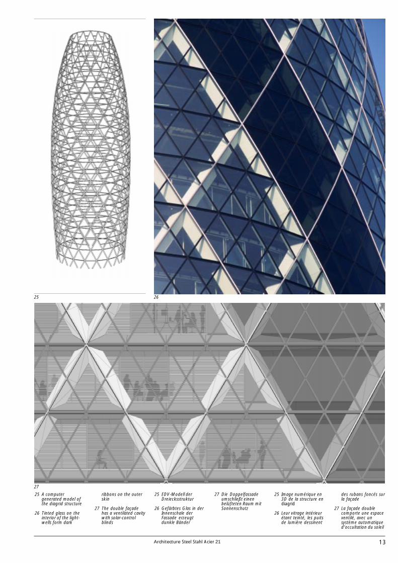
25 A computergenerated model ofthe diagrid structure
26 Tinted glass on theinterior of the light-wells form dark
ribbons on the outerskin
27 The double façadehas a ventilated cavitywith solar-controlblinds
25 Image numérique en3D de la structure endiagrid
26 Leur vitrage intérieurétant teinté, les puitsde lumière dessinent
des rubans foncés surla façade
27 La façade doublecomporte une espaceventilé, avec unsystème automatiqued’occultation du soleil
25 EDV-Modell derDreiecksstruktur
26 Gefärbtes Glas in derInnenschale derFassade erzeugtdunkle Bänder
27 Die Doppelfassadeumschließt einenbelüfteten Raum mitSonnenschutz
14 Architecture Steel Stahl Acier 21
28
29
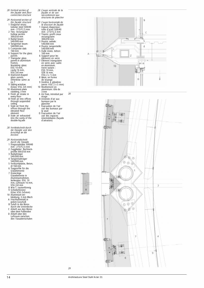
28 Coupe verticale de lafaçade et de sonraccordement auxstructures de plancher
29 Coupe horizontale dela structure de façade
1 Appuis diagonaux :tube d’acier 508/40mm - 273/12,5 mm
2 Tirants: profil creuxrectangulaire300/250 mm
3 Poutre radiale:540/300 mm
4 Poutre tangentielle:540/300 mm
5 Dalle mixte, béton:160 mm
6 Support pour leséléments en verre
7 Élément triangulaireen verre avec cadreen aluminium.Verre isolant :ESG 10 mm,SZR 16 mm,VSG 2 x 5 mm
8 Idem, en formede losange
9 Fenêtre à glissières(verre: VSG 2 x 5 mm)
10 Revêtement enaluminium: tôle de3 mm
A Air frais, introduit parétage
B Amenée d’air auxbureaux par leplancher
C Évacuation de l’airusé des bureaux parle seuil
D Évacuation de l’airusé des espacesintermédiaires (façaded’aération)
28 Vertikalschnitt durchdie Fassade und denAnschluß an dieDecken
29 Horizontalschnittdurch die Fassade
1 Diagonalstäbe 508/40mm - 273/12,5 mm
2 Zugglieder: Rechteck-profile 300/250 mm
3 Radialträger540/300 mm
4 Tangentialträger540/300 mm
5 Verbundplatte, Beton,d=160 mm
6 Tragprofile für dieGlaselemente
7 DreieckigeGlaselemente inAluminiumrahmen.Isolierglas: ESG 10mm, Luftraum 16 mm,VSG 2x5 mm
8 Wie 7, rautenförmig9 Schiebefenster
(Glas: VSG 2x5mm)10 Aluminium ver-
kleidung, 3 mm BlechA Frischlufteinlaß in
jedem GeschoßB Zuluft in die Büros
durch die UnterdeckeC Abluft aus den Büros
über dem FußbodenD Abluft über den
Luftraum zwischenden Fassadenschalen
28 Vertical section ofthe façade and floorconnection structure
29 Horizontal section ofthe façade structure
1 Diagonal struts:tubular steel 508/40mm - 273/12,5 mm
2 Ties: rectangularhollow section300/250 mm
3 Radial beam:540/300 mm
4 Tangential beam:540/300 mm
5 Composite slab:160 mm
6 Support for the glasspanels
7 Triangular glasspanels in aluminiumframes.Insulating glass:ESG 10 mm,cavity 16 mm,VSG 2x5 mm
8 Diamond shapedglass panels,otherwise same asno 7
9 Sliding window(Glass: VSG 2x5 mm)
10 Aluminium platecladding, 3 mm
A Fresh air intake inevery floor
B Fresh air into officesthrough suspendedceiling
C Stale air from theoffices through theelevated floorelement
D Stale air exhaustedinto the cavity of thedouble-façade
15Architecture Steel Stahl Acier 21
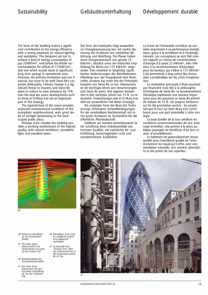
The form of the building makes a signifi-cant contribution to the energy efficiency,with a strong emphasis on natural lightingand ventilation. The designers set out toachieve a level of energy consumption ofjust 25kWh/m², well below the British rec-ommendation for offices of 175kWh/m²,and one which would result in significantlong term savings in operational costs.However, the primary motivation was not fi-nancial, but more to do with Swiss Re’s cor-porate philosophy. Climate change is a sig-nificant threat to insurers, and Swiss Replans to reduce its own emissions by 15%over the next ten years; developments suchas those at St Mary Axe are an importantpart of this strategy.
The tapered base of the tower providesimproved environmental conditions in theimmediate neighbourhood, with good lev-els of sunlight penetrating to the land-scaped public plaza.
Perhaps most notably the building pro-vides a working environment of the highestquality, with natural ventilation, wonderfullight, and excellent views.
Sustainability
30
31
30 Wind test simulationof the constructionmodel
31 The new towerblends well in theenvironment as a partof the London City
Développement durable
La forme de l’immeuble contribue de ma-nière importante à sa performance énergé-tique, grâce à la ventilation et à l’éclairagenaturels. Les concepteurs se sont fixé com-me objectif un niveau de consommationd’énergie d’à peine 25 kWh/m2, bien infé-rieur à la recommandation britanniquepour les bureaux qui s’élève à 175 kWh/m2.Cela permettrait à long terme des écono-mies considérables sur les coûts d’exploita-tion.
La motivation principale n’était pourtantpas financière mais liée à la philosophied’entreprise de Swiss Re. Le bouleversementclimatique représente une menace impor-tante pour les assureurs et Swiss Re prévoitde réduire de 15 % ses propres émissionssur les dix prochaines années ; les projetstels que la tour sur Saint Mary Axe contri-buent pour une part essentielle à cette stra-tégie.
La base fuselée de la tour améliore lesconditions environnementales de son voisi-nage immédiat, cela permet à la place pu-blique paysagée de bénéficier d’un bon ni-veau d’ensoleillement.
Le bâtiment est particulièrement remar-quable pour l’excellente qualité de l’envi-ronnement de travail qu’il offre, avec uneventilation naturelle, une lumière abondan-te et des points de vue superbes.
30 Simulation d’un essaien soufflerie à partird’un maquettenumérique
31 La nouvelle tours’intègre bien dansson environnement etfait maintenant partiede la City
Gebäudeunterhaltung
Die Form des Gebäudes trägt wesentlichzur Energieausnutzung bei; mit starker Be-tonung der Ausbeute von natürlicher Be-lichtung und Belüftung. Die Planer habeneinen Energieverbrauch von gerade 25KWh/m2, deutlich unter der britischen Emp-fehlung für Büros von 175 KWh/m2 ange-strebt. Dies resultiert in langfristig signifi-kanten Reduzierungen der Betriebskosten.Allerdings war der Hauptgrund kein finan-zieller, sondern hat mehr mit der Firmenphi-losophie von Swiss Re zu tun. Klimaschutzist ein wichtiges Motiv von Versicherungenund Swiss Re plant, ihre eigenen Emissio-nen in den nächsten Jahren um 15 % zu re-duzieren. Entwicklungen wie in St Mary Axesind ein wesentlicher Teil dieser Strategie.
Die verjüngte Form der Basis des Turmserzeugt verbesserte Umweltbedingungenfür die unmittelbare Nachbarschaft mit ei-ner guten Ausbeute an Sonnenlicht für dieöffentliche Platzlandschaft.
Vielleicht am meisten bemerkenswert istdie Schaffung eines Arbeitsumfelds vonhöchster Qualität, mit natürlicher Be- undEntlüftung, hervorragendem Licht undwunderschönen Ausblicken.
30 Windsimulation desKonstruktionsmodells
31 Der neue Turmharmoniert sehr gutmit seiner Umgebungals Teil der LondonerCity
16 Architecture Steel Stahl Acier 21
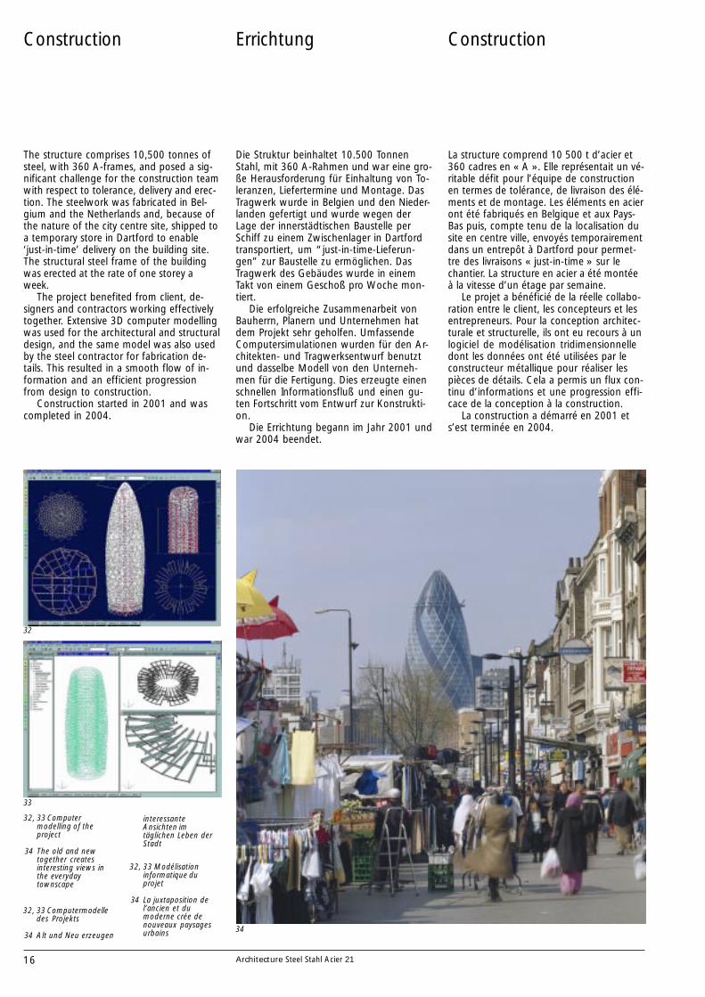
The structure comprises 10,500 tonnes ofsteel, with 360 A-frames, and posed a sig-nificant challenge for the construction teamwith respect to tolerance, delivery and erec-tion. The steelwork was fabricated in Bel-gium and the Netherlands and, because ofthe nature of the city centre site, shipped toa temporary store in Dartford to enable‘just-in-time’ delivery on the building site.The structural steel frame of the buildingwas erected at the rate of one storey aweek.
The project benefited from client, de-signers and contractors working effectivelytogether. Extensive 3D computer modellingwas used for the architectural and structuraldesign, and the same model was also usedby the steel contractor for fabrication de-tails. This resulted in a smooth flow of in-formation and an efficient progressionfrom design to construction.
Construction started in 2001 and wascompleted in 2004.
Construction
32
33
34
32, 33 Computermodelling of theproject
34 The old and newtogether createsinteresting views inthe everydaytownscape
Construction
La structure comprend 10 500 t d’acier et360 cadres en « A ». Elle représentait un vé-ritable défit pour l’équipe de constructionen termes de tolérance, de livraison des élé-ments et de montage. Les éléments en acieront été fabriqués en Belgique et aux Pays-Bas puis, compte tenu de la localisation dusite en centre ville, envoyés temporairementdans un entrepôt à Dartford pour permet-tre des livraisons « just-in-time » sur lechantier. La structure en acier a été montéeà la vitesse d’un étage par semaine.
Le projet a bénéficié de la réelle collabo-ration entre le client, les concepteurs et lesentrepreneurs. Pour la conception architec-turale et structurelle, ils ont eu recours à unlogiciel de modélisation tridimensionnelledont les données ont été utilisées par leconstructeur métallique pour réaliser lespièces de détails. Cela a permis un flux con-tinu d’informations et une progression effi-cace de la conception à la construction.
La construction a démarré en 2001 ets’est terminée en 2004.
32, 33 Modélisationinformatique duprojet
34 La juxtaposition del’ancien et dumoderne crée denouveaux paysagesurbains
Die Struktur beinhaltet 10.500 TonnenStahl, mit 360 A-Rahmen und war eine gro-ße Herausforderung für Einhaltung von To-leranzen, Liefertermine und Montage. DasTragwerk wurde in Belgien und den Nieder-landen gefertigt und wurde wegen derLage der innerstädtischen Baustelle perSchiff zu einem Zwischenlager in Dartfordtransportiert, um “just-in-time-Lieferun-gen” zur Baustelle zu ermöglichen. DasTragwerk des Gebäudes wurde in einemTakt von einem Geschoß pro Woche mon-tiert.
Die erfolgreiche Zusammenarbeit vonBauherrn, Planern und Unternehmen hatdem Projekt sehr geholfen. UmfassendeComputersimulationen wurden für den Ar-chitekten- und Tragwerksentwurf benutztund dasselbe Modell von den Unterneh-men für die Fertigung. Dies erzeugte einenschnellen Informationsfluß und einen gu-ten Fortschritt vom Entwurf zur Konstrukti-on.
Die Errichtung begann im Jahr 2001 undwar 2004 beendet.
Errichtung
32, 33 Computermodelledes Projekts
34 Alt und Neu erzeugen
interessanteAnsichten imtäglichen Leben derStadt
Architecture Steel Stahl Acier 20
European SteelInformationSources
Architecture Steel Stahl Acier is intended to providearchitects with a series of case studies of notablebuildings built with steel.
EditorECCS-European Convention for ConstructionalSteelwork
TextProfessor Roger Plank
TranslationsPeter Cziffer, GermanCedam, France
Design and lay outEsko Miettinen, architect
Photographs1,3,11-13,26,31,34, cover, back coverNigel Young/Foster and Partners16,22 Victor Buyck
DrawingsFoster and Partners
Printed byLibris 12/2005
AUSTRIA
ÖsterreichischerStahlbauverband *Wiedner Hauptstraße 63A-1045 Wien
Tel: +43 1 503 9474Fax: +43 1 503 9474 227
BELGIUM
Agoria *Diamant Building, Bld A. Reyers 80B-1030 Brussels
Tel: +32 2 706 7962Fax: +32 2 706 7966
Centre Information AcierStaalinfocentrum (CIA)Chaussée de Zellik 12, 1082 BruxellesZelliksesteenweg 12, 1082 Brussel
Tel: +32 2 509 1504Fax: +32 2 511 1281
CZECH REPUBLIC
Czech ConstructionalSteelwork Association *Ceskobratsrska 6, 702 00 Ostrava
Tel: +420 59 513 6026Fax: +420 59 513 6026
DENMARK
Dansk Stålinstitut *Gydevang 39-41, 3450 Allerød
Tel: +45 66 130 888Fax: +45 65 918 789
FINLAND
Technology Industriesof Finland *Eteläranta 10, FIN-00130 Helsinki
Tel: +358 9 192 31Fax: +358 9 624 462
Finnish ConstructionalSteelwork AssociationUnioninkatu 14, FIN-00130 Helsinki
Tel: +358 9 129 91Fax: +358 9 129 9214
FRANCE
Syndicat de la constructionmétallique de France(SCMF) *20, rue Jean-JaurèsF-92807 Puteaux Cedex
Tel: +33 1 47 74 66 15Fax: +33 1 40 90 08 60
Office technique pourl’utilisation de l’acier (OTUA)13, cours ValmyF-92070 Paris La Défense
Tel: +33 1 41 67 04 02Fax: +33 1 41 25 55 70
GERMANY
Deutscher Stahlbau-VerbandDSTV *Sohnstraße 65, D-40237 Düsseldorf
Tel: +49 211 6707 800Fax: +49 211 6707 820
ITALY
Associazione fra i Costruttoriin Acciaio Italiani *Viale Abruzzi 66, I-20131 Milano
Tel: +39 02 2951 3413Fax: +39 02 2952 9824
Promozione AcciaioPiazza Velasca 10, I-20122 Milano
Tel: +39 02 8631 3020Fax: +39 02 8631 3031
LUXEMBOURG
Arcelor SectionsCommercial *66 rue de LuxembourgL-4009 Esch/Alzette
Tel: +352 5313 3060Fax: +352 5313 3095
Centre belgo-luxembourgeoisInformation Acier (CIA)Chaussée de Zellik 12, 1082 BruxellesZelliksesteenweg 12, 1082 Brussel
Tel: +32 2 509 1504Fax: +32 2 511 1281
NETHERLANDS
SamenwerkendeNederlandse Staalbouw(SNS) *Boerhaavelaan 40, Postbus 190NL-2700 AD Zoetermeer
Tel: +31 79 353 1265Fax: +31 79 353 1365
NORWAY
Norsk Stalforbund/NorwegianSteel Association *P.O.Box 242, NO-1326 Lysaker
Tel: +47 6783 8600Fax: +47 6783 8601
PORTUGAL
Associação Portuguesa deConstrução Metálica e Mista(Cmm) *University of Coimbra,Polo II - Pinhal de MarrocosPT- 3030 Coimbra
Tel: +351 239 797 218Fax: +351 239 797 217
ROMANIA
Asociatia Producatorilor deConstructii Metalice DinRomania (APCMR) *1, Piata Iancu de HunedoaraRO- 2750 Hunedoara
Tel: +40 254 740 200Fax: +40 254 717 650
SLOVAKIA
Slovak Association of SteelConstructions (SASC)Radlinského 11, 813 68 Bratislava
Tel: +421 2 52 964 404Fax: +421 2 52 494 116
SLOVENIA
Institut za MetalneKonstrukcije *Mencingerjeva 7, SI-1000 Ljubljana
Tel: +386 1 280 21 02Fax: +386 1 280 21 51
SPAIN
Asociación para laConstrucción deEstructuras Metálicas *Plaça de la Unió, 1 Edificio B 1° 2a
ES-08190 Sant Cugat del Vallés
Tel: +34 93 589 3636Fax: +34 93 590 8249
APTAAsociación para laPromoción de las Tecnicasdel AceroPaseo de la Castellana 135Edificio Cuzco III, 3o BES-28046 Madrid
Tel: +34 91 567 0910Fax: +34 91 567 0911
SWEDEN
Swedish Institute ofSteel Construction *Box 27751, S-115 92 Stockholm
Tel: +46 8 661 0280Fax: +46 8 661 0305
SWITZERLAND
Stahlbau Zentrum Schweiz/Centre Suisse de laConstruction Métallique *Seefeldstraße 25, CH-8034 Zürich
Tel: +41 1 261 8980Fax: +41 1 262 0962
TURKEY
Turkish Constructional Steel-work Association (TUCSA) *Bayramaga Sokak No 20/A34662 Altunizade, Istanbul
Tel: +90 216 474 3135Fax: +90 216 474 3388
UNITED KINGDOM
British ConstructionalSteelwork Association *4 Whitehall Court - WestminsterLondon SW1A 2ES
Tel: +44 20 7839 8566Fax: +44 20 7976 1634
Corus Construction& IndustrialFrodingham HouseBrigg Road, ScunthorpeNorth Lincolnshire DN16 1BP
Tel: +44 1724 402 185Fax: +44 1724 404 224
Steel ConstructionInstitute (SCI)Silwood ParkBuckhurst RoadAscot, Berkshire SL5 7Qn
Tel: +44 1344 623 345Fax: +44 870 622 944
ECCS General SecretariatAvenue des Ombrages 32/20,B-1200 Brussels
Tel: +32 2 762 0429Fax: +32 2 762 0935
* ECCS Full Members
Architecture Steel Stahl Acier 21
ArchitectureSteel Stahl Acier
1 Brussimmo HouseBrussels, BelgiumSamyn and Partners
2 L’Oréal FactoryParis, FranceDenis Valode,Jean Pistre et associés
3 TAZ, Berlin, GermanyGerhard SpangenbergBrigitte Steinkilberg
4 RFB Building, AustriaCoop Himmelblau
5 The GuggenheimMuseumBilbao, SpainFrank O. Gehry andAssociates
Previously published ECCS Case Studies
6 Turku Academy of ArtFinlandLaiho-Pulkkinen-Raunio Architects
7 Dogan Printing CenterTurkeyTabanlioglu Architecture& Consulting
8 Terminal 3Copenhagen AirportDanmarkVilhelm Lauritzen A/S
9 Terminal 2F RoissyFrancePaul Andreu
10 The Reichstag Berlin,GermanySir Norman Foster
11 Service StationsHouten, The NetherlandsOrival area, BelgiumSamyn and PartnersService Station HietalahtiHelsinki, FinlandJuha Ilonen
12 Lucerne Cultural andConvention CentreSwitzerlandArchitectures Jean Nouvel
13 Office buildingPhoenixstraat 60,Delft, The NetherlandsCepezed b.v.
14 The Eden ProjectCornwall, UKNicholas Grimshaw &Partners
15 House R 128 Stuttgart,GermanyWerner Sobek
16 TGV stationsValence, Avignon,Aix-en Provence, FranceAgence des gares et AREP
17 Olympic StadiumIstanbul, TurkeyMichel Macary,Aymeric Zublena
18 Town hallAlphen aan den RijnThe Netherlands(EEA) Erick van Egeraatassociated architects
19 Double-skin façadesSanoma HouseSarc ArchitectsBaltic Sea TowerHelin & Co ArchitectsRadiolinjaTommila Architects
20 50 years of steelarchitecture in Europe
The Swiss Re tower has been created as anenvironmentally responsible building withnatural economy of form, fully sympatheticwith its urban context, and forming ahumanised workplace of the highestquality.
La tour Swiss Re a été conçue suivant unedémarche respectueuse de l’environnementaboutissant à une simplicité formelle, unetrès bonne intégration au contexte urbain,à un lieu de travail à dimension humaine detrès haute qualité.
Der Swiss Re Tower wurde als ein für dieUmwelt wesentliches Gebäude mit einernatürlichen Wirtschaftlichkeit der Form,einer völligen Übereinstimmung mit seinemurbanen Kontext und der Gestaltungmenschlicher Arbeitsplätze von höchsterQualität geschaffen.