Embed Size (px)
Citation preview
INL/EXT-05-00479
U.S. Department of Energy
FreedomCAR & Vehicle Technologies Program Advanced Vehicle Testing Activity
KATECH (Lithium Polymer) 4-Passenger NEV Range and Battery Testing Report
Donald Karner James Francfort
July 2005
Idaho National Laboratory Operated by Battelle Energy Alliance
INL/EXT-05-00479
U.S. Department of Energy FreedomCAR & Vehicle Technologies Program
Advanced Vehicle Testing Activity
KATECH (Lithium Polymer) 4-Passenger NEV Range and Battery Testing Report
Donald Karnera James Francfortb
July 2005
Idaho National Laboratory Transportation Technology Department
Idaho Falls, Idaho 83415
Prepared for the U.S. Department of Energy
Assistant Secretary for Energy Efficiency and Renewable Energy Under DOE Idaho Operations Office
Contract DE-AC07-05ID14517
a Electric Transportation Applications b Idaho National Laboratory
Disclaimer This document highlights work sponsored by agencies of the U.S. Government. Neither the U.S. Government nor any agency thereof, nor any of their employees, makes any warranty, express or implied, or assumes any legal liability or responsibility for the accuracy, completeness, or usefulness of any information, apparatus, product, or process disclosed, or represents that its use would not infringe privately owned rights. Reference herein to any specific commercial product, process, or service by trade name, trademark, manufacturer, or otherwise does not necessarily constitute or imply its endorsement, recommendation, or favoring by the U.S. Government or any agency thereof. The views and opinions of authors expressed herein do not necessarily state or reflect those of the U.S. Government or any agency thereof.
2
ABSTRACT
The U.S. Department of Energy’s (DOE’s) Advanced Vehicle Testing Activity (AVTA) received a Neighborhood Electric Vehicle (NEV) from the Korea Automotive Technology Institute (KATECH) for vehicle and battery characterization testing. The KATECH NEV (called the Invita) was equipped with a lithium polymer battery pack from Kokam Engineering. The Invita was to be baseline performance tested by AVTA’s testing partner, Electric Transportation Applications (ETA), at ETA’s contract testing facilities and test track in Phoenix, Arizona, to AVTA’s NEVAmerica testing specifications and procedures.
Before and during initial constant speed range testing, the Invita battery pack experienced cell failures, and the onboard charger failed. A Kokam-supplied off-board charger was used in place of the onboard charger to successfully perform a constant speed range test on the Invita. The Invita traveled a total of 47.9 miles in 1 hour 47 minutes, consuming 91.3 amp-hours and 6.19 kilowatt-hours.
The Kokam Engineering lithium polymer battery was also scheduled for battery pack characterization testing, including the C/3 energy capacity, dynamic stress, and peak power tests. Testing was stopped during the initial C/3 energy capacity test, however, because the battery pack failed to withstand cycling without cell failures. After the third discharge/charge sequence was completed, it was discovered that Cell 6 had failed, with a voltage reading of 0.5 volts. Cell 6 was replaced, and the testing sequence was restarted. After the second discharge/charge sequence was complete, it was discovered that Cell 1 had failed, with its voltage reading 0.2 volts. At this point it was decided to stop all battery pack testing. During the discharge cycles, the battery pack supplied 102.21, 94.34, and 96.05 amp-hours consecutively before Cell 6 failed. After replacing Cell 6, the battery pack supplied 98.34 and 98.11 amp-hours before Cell 1 failed.
The Idaho National Laboratory managed these testing activities for the AVTA, as part of DOE’s FreedomCAR and Vehicle Technologies Program.
3
CONTENTS
ABSTRACT.................................................................................................................................................. 3
1. INTRODUCTION.............................................................................................................................. 5
2. VEHICLE TESTING ......................................................................................................................... 6
3. CHARGER TESTING RESULTS ..................................................................................................... 7
4. CONSTANT SPEED RANGE TESTING DETAILS........................................................................ 9
5. KOKAM LITHIUM POLYMER BATTERY CHARACTERIZATION ........................................ 16
Appendix A—Vehicle Photographs............................................................................................................ 20
Appendix B—NEV America Technical Specifications.............................................................................. 26
4
KATECH (Lithium Polymer) 4-Passenger NEV Range and Battery Testing Report
1. INTRODUCTION
The U.S. Department of Energy’s (DOE’s) Advanced Vehicle Testing Activity (AVTA) received a Neighborhood Electric Vehicle (NEV) from the Korea Automotive Technology Institute (KATECH) for baseline performance testing. The KATECH NEV (called the Invita) was to be tested using the test specifications and procedures developed for AVTA’s NEVAmerica testing program. The NEVAmerica testing includes constant speed range, rough road, handling, braking, acceleration, and charger performance tests (http://avt.inl.gov/nev.shtml) specific to pure-electric vehicles classified as NEVs. NEVs are four-wheeled vehicles defined by the National Highway Traffic Safety Administration as subject to Federal Motor Vehicle Safety Standard No. 500 (49 CFR 571.500). Per FMVSS 500, NEVs have top speeds of between 20 and 25 mph and are defined as low speed vehicles (LSVs). While low speed vehicle is technically the correct term, NEV has become the term used by industry and fleets to refer to passenger vehicles subject to FMVSS 500.
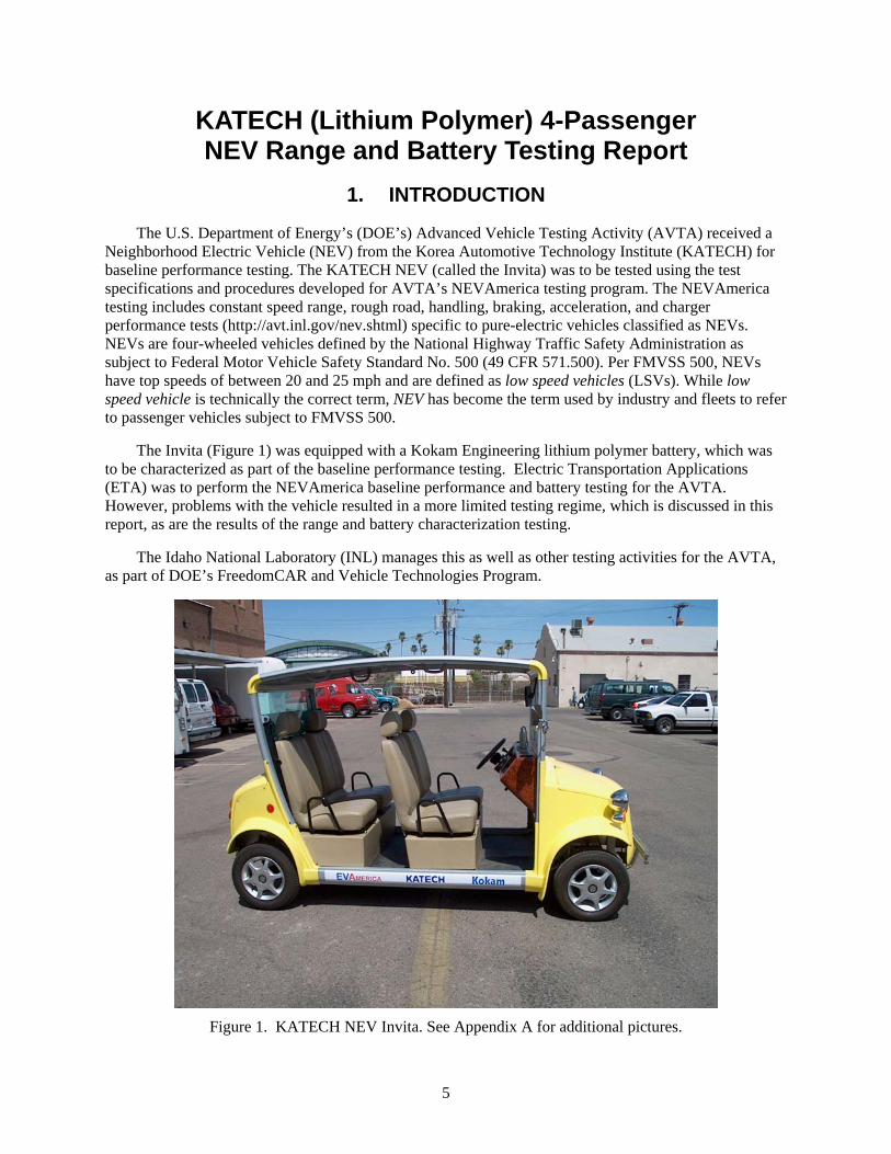
The Invita (Figure 1) was equipped with a Kokam Engineering lithium polymer battery, which was to be characterized as part of the baseline performance testing. Electric Transportation Applications (ETA) was to perform the NEVAmerica baseline performance and battery testing for the AVTA. However, problems with the vehicle resulted in a more limited testing regime, which is discussed in this report, as are the results of the range and battery characterization testing.
The Idaho National Laboratory (INL) manages this as well as other testing activities for the AVTA, as part of DOE’s FreedomCAR and Vehicle Technologies Program.
Figure 1. KATECH NEV Invita. See Appendix A for additional pictures.
5
2. VEHICLE TESTING
The Invita arrived at ETA’s facility in Phoenix, Arizona, on June 17, 2004, and it was immediately determined that Cell 7 of the 18-cell lithium polymer battery pack was damaged and needed to be replaced. After replacing Cell 7, the vehicle was driven and charged to cycle the battery pack in preparation for being shipped to the test track operated by the ETA contractor, Exponent, to begin the NEVAmerica baseline performance testing. Before testing, it was discovered that the software in the onboard charger was not performing as intended and was terminating the charge sequence when any one of the cells reached a predetermined voltage, thus not allowing the lower voltage cells to equalize. Because the battery state-of-charge (SOC) was in the 80% range at the end of a charge sequence, Kokam advised ETA to begin testing despite the flawed charging algorithm. On July 7th, the Invita was constant speed range tested to determine the official range of the vehicle. (During constant speed range testing, a NEV is driven on a banked track at top speed until it cannot maintain a speed of 18 mph. See http://avt.inel.gov/pdf/nev/ntp004.pdf for the constant speed range test procedure).
The constant speed range test was to be terminated when any of the cells reached 3.0 volts, as recommended by Kokam. The cells were monitored, with the results shown on a dashboard-mounted display that reported each cell’s voltage, the overall battery pack voltage, and SOC. Just over an hour into the constant speed range test, the voltages for Cells 2 and 16 began to fall more rapidly than the other cells, and by 34 miles Cell 2 had reached the 3.0-volt cutoff point. Because this range was considerably lower than what was expected, and the cells did not discharge evenly, the vehicle was taken out of the test program and brought back to ETA for analysis. After charging and discharging the battery pack, it was determined that Cell 2 did not have the amp-hour capacity of the other cells and would not be able to maintain the load requirements of the vehicle during range testing. Cell 16 was found to be consistently undercharged: when the onboard charger would terminate, it was always the lowest in voltage by up to 0.4 volts. Kokam agreed to send an off-board charger to be used to equalize the pack. The new charger successfully charged and equalized all 18 cells, and the vehicle was determined to be ready for constant speed range testing again. During preliminary range testing, however, Cell 2 proved to still lack capacity, so it was replaced.
During the official constant speed range test, the Invita was driven for 1 hour 47 minutes, consuming 91.3 amp-hours and 6.19 kilowatt-hours, while traveling a total of 47.9 miles. Cell 16 was the first cell to reach 3.0 volts, but the others were close behind; the cell’s voltages remained fairly close during the entire test. When comparing the range attained at Exponent to the range data provided by Kokam, it appears that the battery pack had either degraded or was not operating at full capacity. Therefore, it was decided to limit the vehicle testing to the above constant speed range test and the few tests already conducted, including acceleration time to 20 mph on a level grade (5 seconds), maximum speed attainable on a level grade (25 mph), and maximum grade attainable from a standing start at GVWR (24%). Appendix B presents these results and the vehicle’s specifications that were collected before the testing as curtailed.
6
3. CHARGER TESTING RESULTS
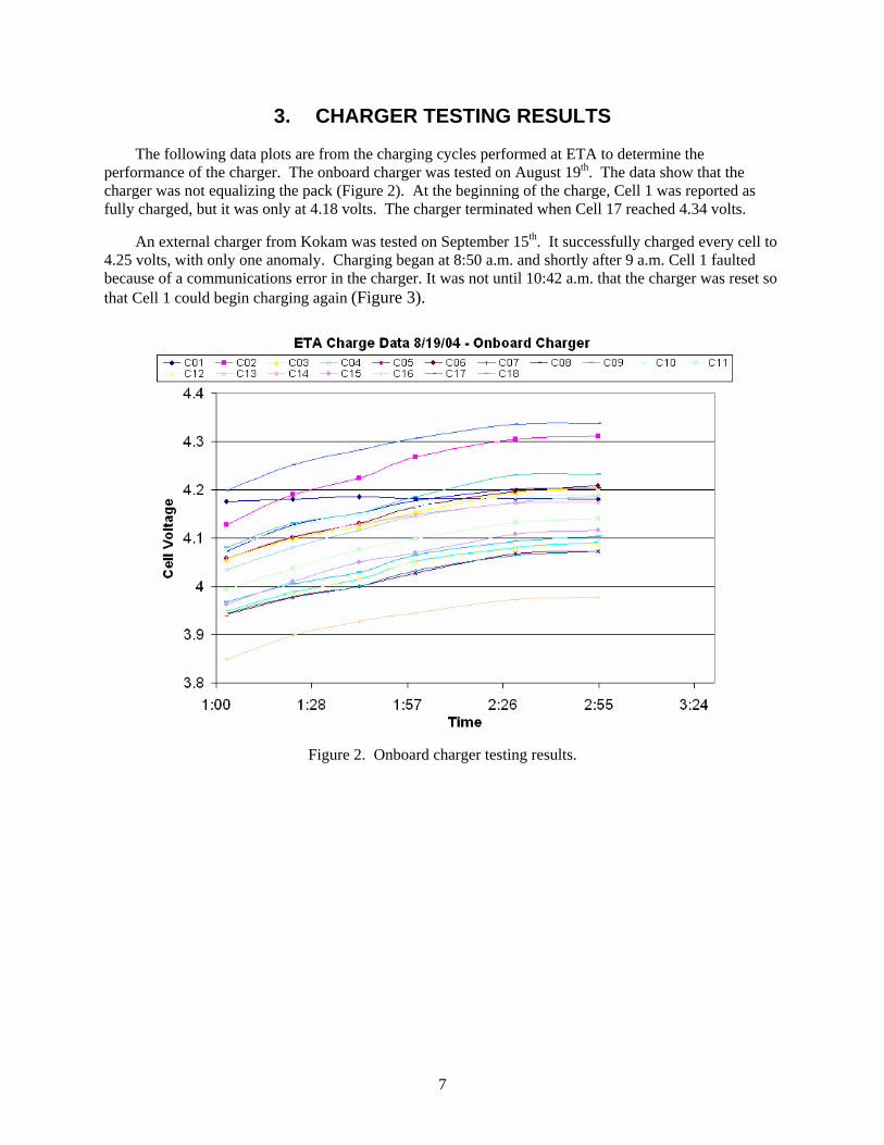
The following data plots are from the charging cycles performed at ETA to determine the performance of the charger. The onboard charger was tested on August 19th. The data show that the charger was not equalizing the pack (Figure 2). At the beginning of the charge, Cell 1 was reported as fully charged, but it was only at 4.18 volts. The charger terminated when Cell 17 reached 4.34 volts.
An external charger from Kokam was tested on September 15th. It successfully charged every cell to 4.25 volts, with only one anomaly. Charging began at 8:50 a.m. and shortly after 9 a.m. Cell 1 faulted because of a communications error in the charger. It was not until 10:42 a.m. that the charger was reset so that Cell 1 could begin charging again (Figure 3).
Figure 2. Onboard charger testing results.
7
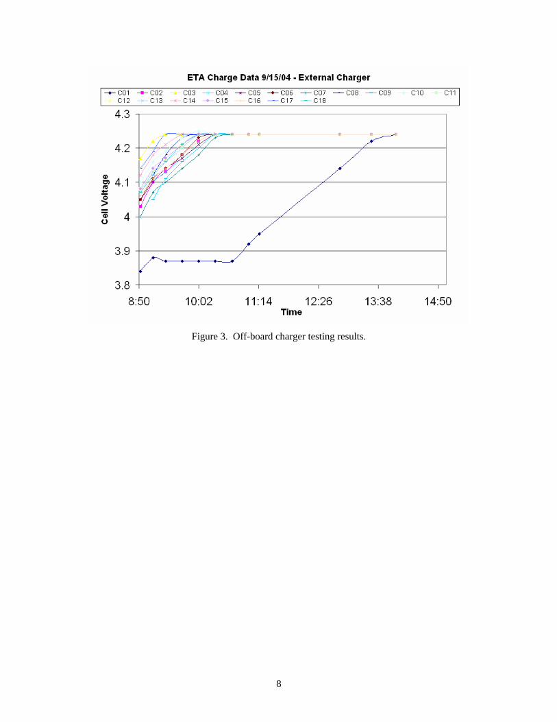
Figure 3. Off-board charger testing results.
8
4. CONSTANT SPEED RANGE TESTING DETAILS
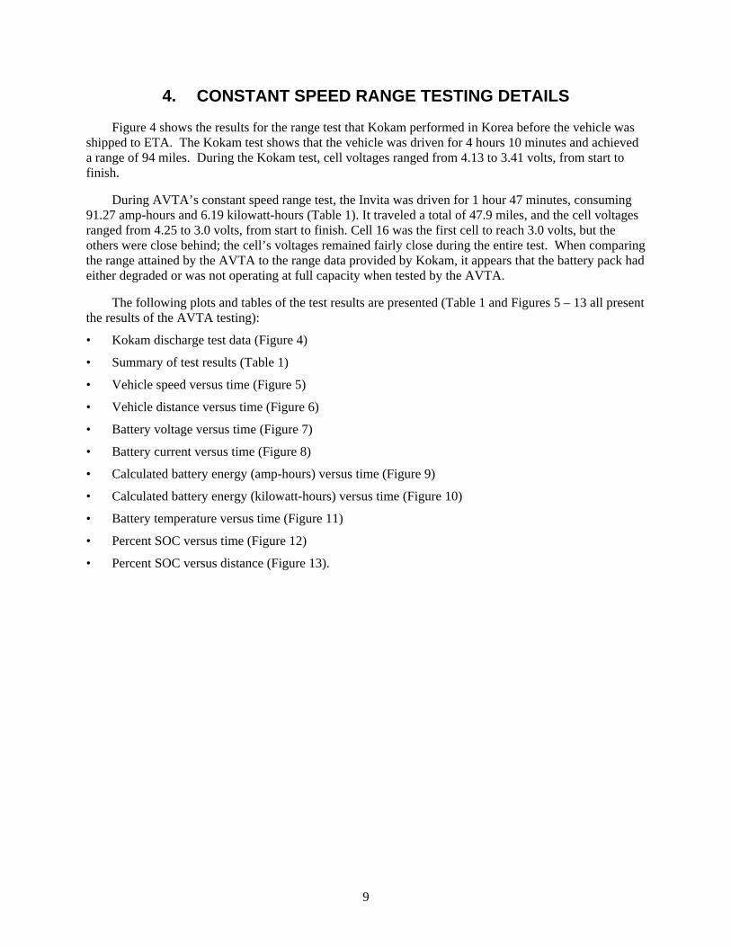
Figure 4 shows the results for the range test that Kokam performed in Korea before the vehicle was shipped to ETA. The Kokam test shows that the vehicle was driven for 4 hours 10 minutes and achieved a range of 94 miles. During the Kokam test, cell voltages ranged from 4.13 to 3.41 volts, from start to finish.
During AVTA’s constant speed range test, the Invita was driven for 1 hour 47 minutes, consuming 91.27 amp-hours and 6.19 kilowatt-hours (Table 1). It traveled a total of 47.9 miles, and the cell voltages ranged from 4.25 to 3.0 volts, from start to finish. Cell 16 was the first cell to reach 3.0 volts, but the others were close behind; the cell’s voltages remained fairly close during the entire test. When comparing the range attained by the AVTA to the range data provided by Kokam, it appears that the battery pack had either degraded or was not operating at full capacity when tested by the AVTA.
The following plots and tables of the test results are presented (Table 1 and Figures 5 – 13 all present the results of the AVTA testing):
• Kokam discharge test data (Figure 4)
• Summary of test results (Table 1)
• Vehicle speed versus time (Figure 5)
• Vehicle distance versus time (Figure 6)
• Battery voltage versus time (Figure 7)
• Battery current versus time (Figure 8)
• Calculated battery energy (amp-hours) versus time (Figure 9)
• Calculated battery energy (kilowatt-hours) versus time (Figure 10)
• Battery temperature versus time (Figure 11)
• Percent SOC versus time (Figure 12)
• Percent SOC versus distance (Figure 13).
9
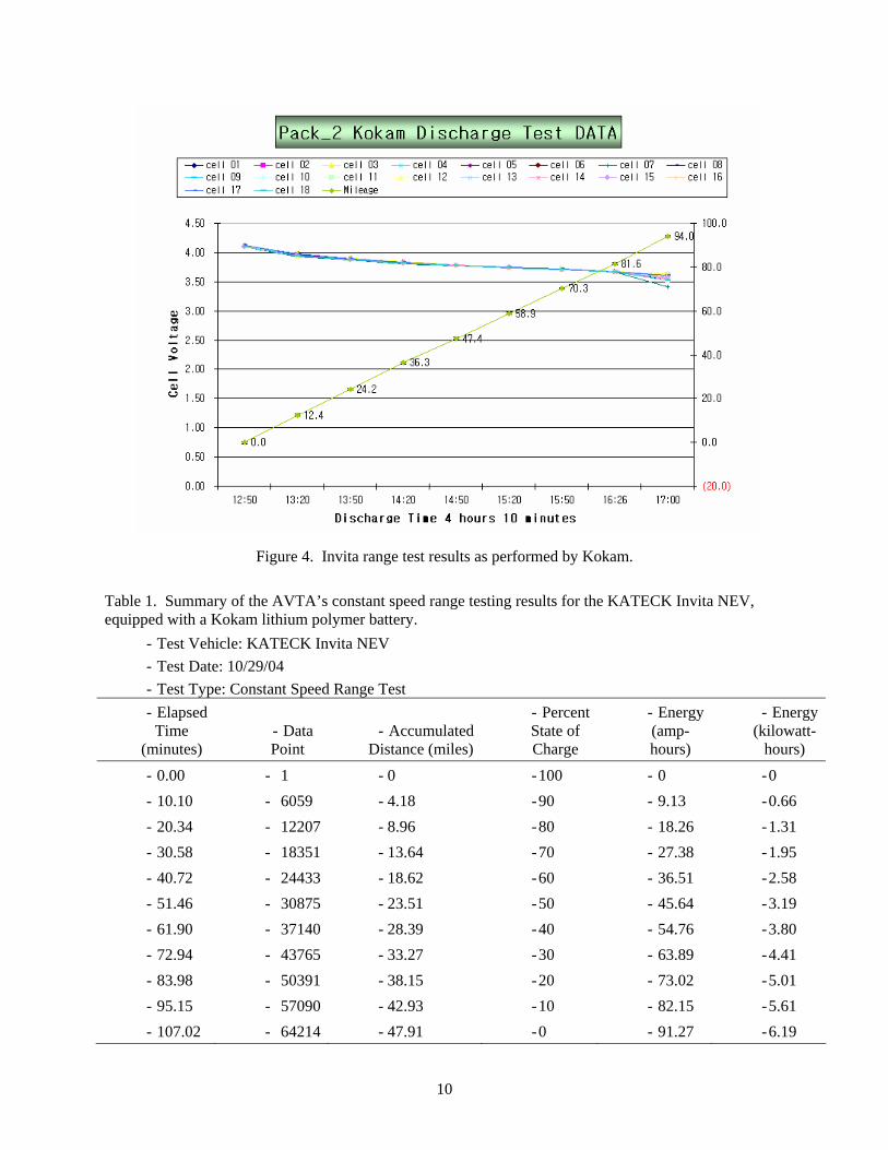
Figure 4. Invita range test results as performed by Kokam.
Table 1. Summary of the AVTA’s constant speed range testing results for the KATECK Invita NEV, equipped with a Kokam lithium polymer battery.
- Test Vehicle: KATECK Invita NEV - Test Date: 10/29/04 - Test Type: Constant Speed Range Test - Elapsed
Time (minutes)
- Data Point
- Accumulated Distance (miles)
- Percent State of Charge
- Energy (amp-hours)
- Energy(kilowatt-
hours)
- 0.00 - 1 - 0 - 100 - 0 - 0 - 10.10 - 6059 - 4.18 - 90 - 9.13 - 0.66 - 20.34 - 12207 - 8.96 - 80 - 18.26 - 1.31 - 30.58 - 18351 - 13.64 - 70 - 27.38 - 1.95 - 40.72 - 24433 - 18.62 - 60 - 36.51 - 2.58 - 51.46 - 30875 - 23.51 - 50 - 45.64 - 3.19 - 61.90 - 37140 - 28.39 - 40 - 54.76 - 3.80 - 72.94 - 43765 - 33.27 - 30 - 63.89 - 4.41 - 83.98 - 50391 - 38.15 - 20 - 73.02 - 5.01 - 95.15 - 57090 - 42.93 - 10 - 82.15 - 5.61 - 107.02 - 64214 - 47.91 - 0 - 91.27 - 6.19
10
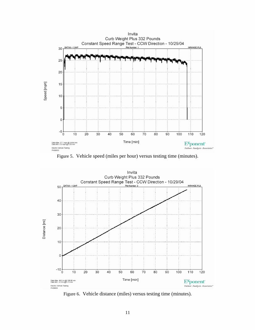
Figure 5. Vehicle speed (miles per hour) versus testing time (minutes).
Figure 6. Vehicle distance (miles) versus testing time (minutes).
11
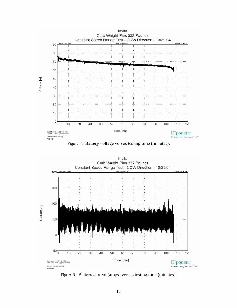
Figure 7. Battery voltage versus testing time (minutes).
Figure 8. Battery current (amps) versus testing time (minutes).
12
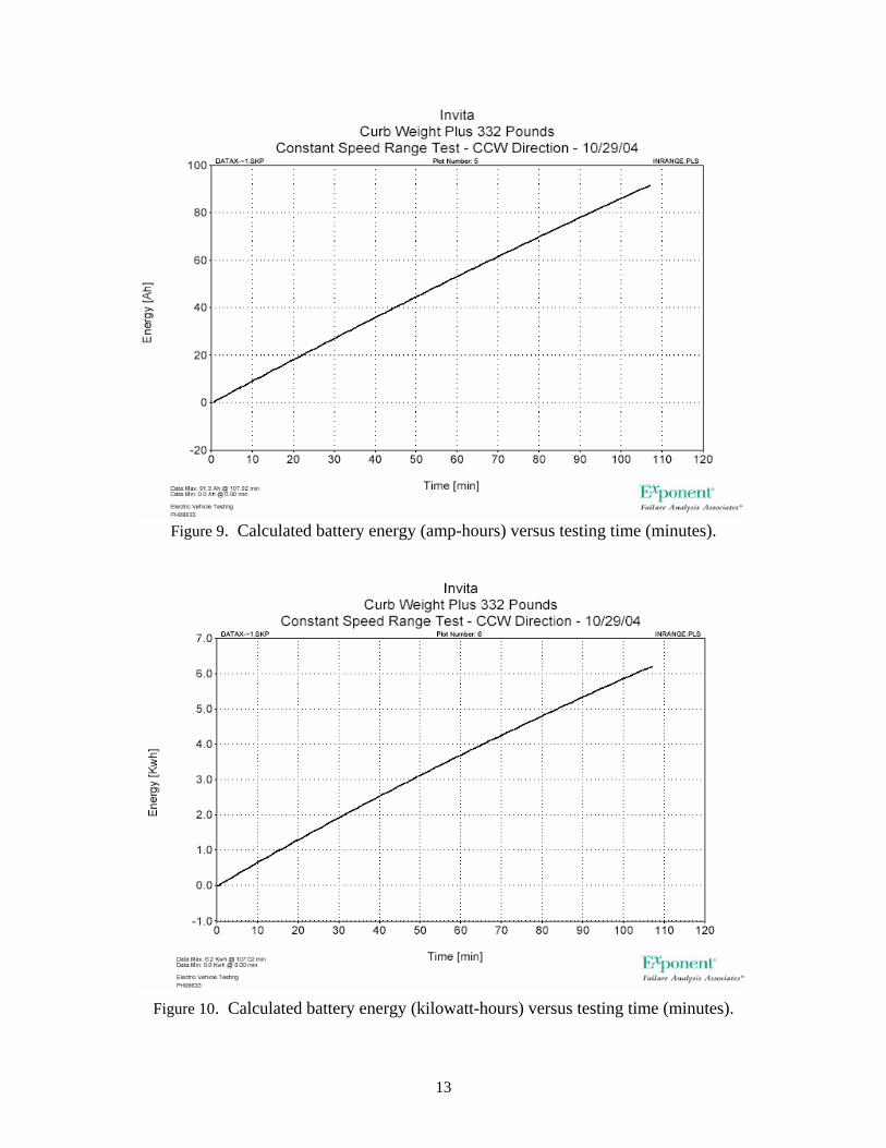
Figure 9. Calculated battery energy (amp-hours) versus testing time (minutes).
Figure 10. Calculated battery energy (kilowatt-hours) versus testing time (minutes).
13
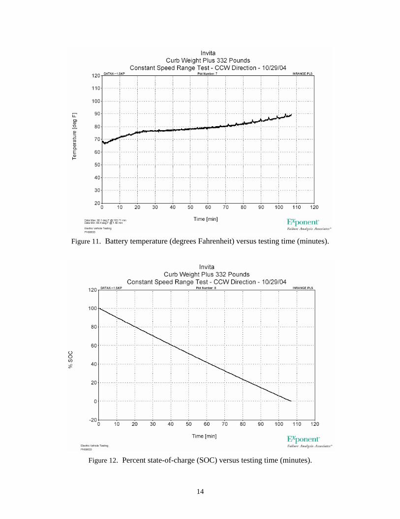
Figure 11. Battery temperature (degrees Fahrenheit) versus testing time (minutes).
Figure 12. Percent state-of-charge (SOC) versus testing time (minutes).
14
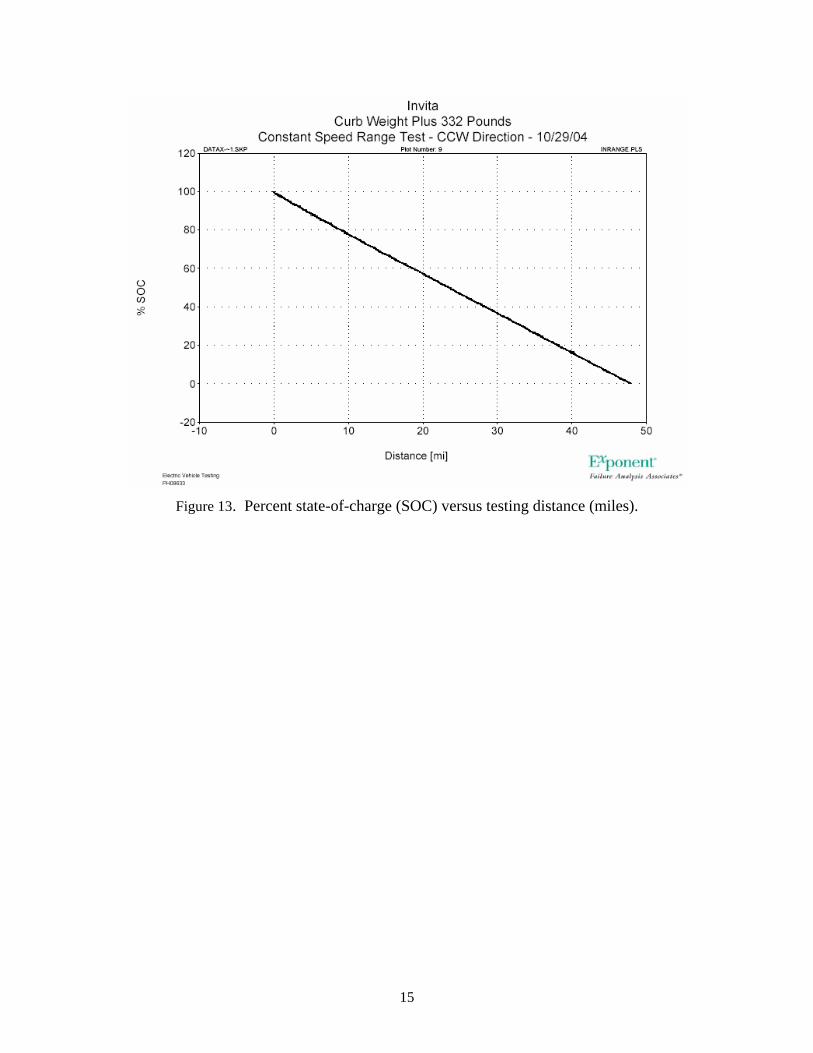
Figure 13. Percent state-of-charge (SOC) versus testing distance (miles).
15
5. KOKAM LITHIUM POLYMER BATTERY CHARACTERIZATION
Characterization testing of the lithium polymer battery began on Wednesday, February 16, 2005, consisting of three procedures: the C/3 energy capacity test, the dynamic stress test, and the peak power test. The C/3 energy capacity test was to determine the energy capacity of the pack by discharging it at 33 amps (C/3) from full charge (4.25 volts) to empty, or 2.7 volts per cell, repeating the process until the energy taken out was repeatable within 2%. Because the battery pack needed to be balanced and equalized by the Kokam charger, a computer-driven battery cycler (ABC 150) was programmed to charge the pack until it reached 73.8 volts, then the Kokam off-board charger was connected to the cells to fully charge them to 4.25 volts. Because the Kokam charger could only charge 13 cells at a time, cells 1–7 and 10–15 were charged first, then the remaining five cells were charged. After all the cells were fully charged, the battery cycler discharged the pack at 33.33 amps until the pack voltage dropped to 48.6 volts, at which point the battery cycler began charging the pack again for the next iteration. Once the energy removed was within 2% of the last two iterations, the test would be deemed complete.
The dynamic stress test was to follow the C/3 test. This test discharges the battery pack at varying power levels while monitoring the pack voltage, current, and temperature to determine how the pack responds to the changing load. The charging sequence of the test is identical to that of the C/3 energy capacity test, but only one cycle was called for by the test plan.
The peak power test was to discharge the pack at 425 amps for 30-second pulses and then reduce the discharge rate to 111 amps until 10% of the energy had been removed. The batter cycler was then to continue this process until either 100% of the pack’s energy had been removed or the pack’s voltage dropped below 48.6 volts. The charging sequence of the test is identical to that of the dynamic stress test.
The testing was stopped during the C/3 energy capacity test because the battery pack could not withstand cycling without cell failures. After the third discharge/charge sequence was completed on the battery cycler, it was discovered that Cell 6 had failed. Its voltage read 0.5 volts after the charge. The cell was replaced, and the testing sequence was started over. After the second discharge/charge sequence was complete, it was discovered that Cell 1 had failed, with its voltage reading 0.2 volts. At that point it was decided to stop all pack testing.
During the discharge cycles, the battery pack supplied 102.21, 94.34, and 96.05 amp-hours consecutively before Cell 6 failed. After replacing Cell 6, the battery pack supplied 98.34 and 98.11 amp-hours before Cell 1 failed. The battery testing was terminated after this failure.
Figure 14 describes the test setup and Table 2 the test plan for the Kokam lithium polymer battery pack testing.
16
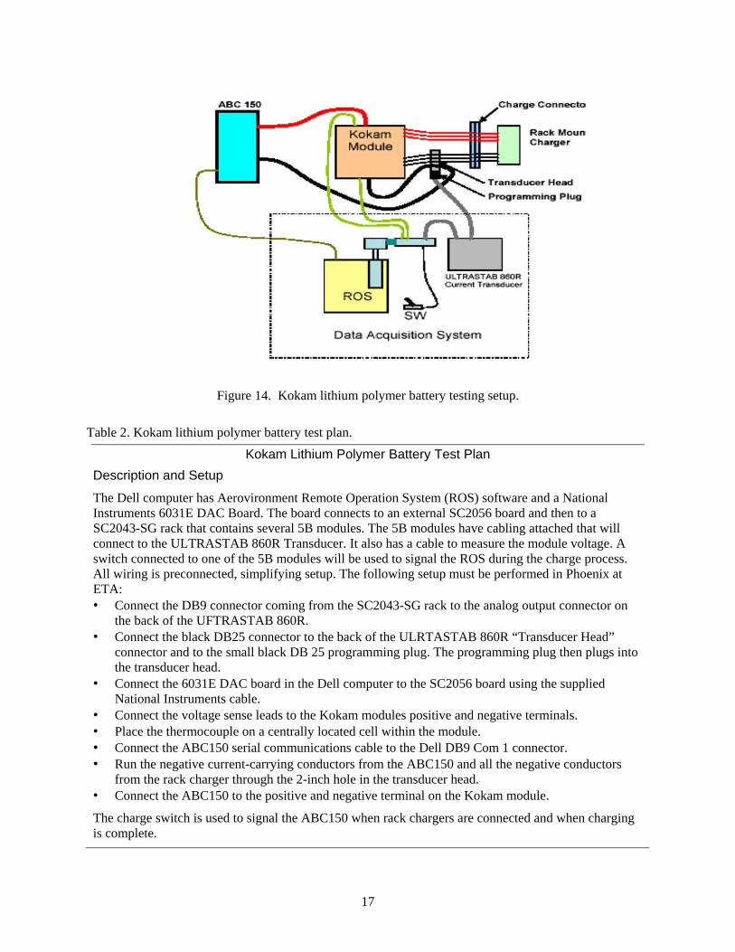
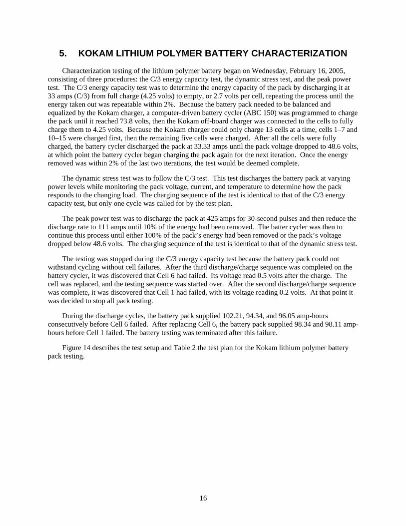
Figure 14. Kokam lithium polymer battery testing setup.
Table 2. Kokam lithium polymer battery test plan.
Kokam Lithium Polymer Battery Test Plan Description and Setup
The Dell computer has Aerovironment Remote Operation System (ROS) software and a National Instruments 6031E DAC Board. The board connects to an external SC2056 board and then to a SC2043-SG rack that contains several 5B modules. The 5B modules have cabling attached that will connect to the ULTRASTAB 860R Transducer. It also has a cable to measure the module voltage. A switch connected to one of the 5B modules will be used to signal the ROS during the charge process. All wiring is preconnected, simplifying setup. The following setup must be performed in Phoenix at ETA: • Connect the DB9 connector coming from the SC2043-SG rack to the analog output connector on
the back of the UFTRASTAB 860R. • Connect the black DB25 connector to the back of the ULRTASTAB 860R “Transducer Head”
connector and to the small black DB 25 programming plug. The programming plug then plugs into the transducer head.
• Connect the 6031E DAC board in the Dell computer to the SC2056 board using the supplied National Instruments cable.
• Connect the voltage sense leads to the Kokam modules positive and negative terminals. • Place the thermocouple on a centrally located cell within the module. • Connect the ABC150 serial communications cable to the Dell DB9 Com 1 connector. • Run the negative current-carrying conductors from the ABC150 and all the negative conductors
from the rack charger through the 2-inch hole in the transducer head. • Connect the ABC150 to the positive and negative terminal on the Kokam module.
The charge switch is used to signal the ABC150 when rack chargers are connected and when charging is complete.
17
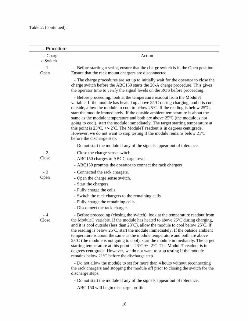
Table 2. (continued).
- Procedure - Charg
e Switch - Action
- 1 Open
- Before starting a script, ensure that the charge switch is in the Open position. Ensure that the rack mount chargers are disconnected.
- The charge procedures are set up to initially wait for the operator to close the charge switch before the ABC150 starts the 20-A charge procedure. This gives the operator time to verify the signal levels on the ROS before proceeding.
- Before proceeding, look at the temperature readout from the ModuleT variable. If the module has heated up above 25ºC during charging, and it is cool outside, allow the module to cool to below 25ºC. If the reading is below 25ºC, start the module immediately. If the outside ambient temperature is about the same as the module temperature and both are above 25ºC (the module is not going to cool), start the module immediately. The target starting temperature at this point is 23ºC, +/- 2ºC. The ModuleT readout is in degrees centigrade. However, we do not want to stop testing if the module remains below 21ºC before the discharge step.
- Do not start the module if any of the signals appear out of tolerance. - 2
Close - Close the charge sense switch. - ABC150 charges to ABCChargeLevel. - ABC150 prompts the operator to connect the rack chargers.
- 3 Open
- Connected the rack chargers. - Open the charge sense switch. - Start the chargers. - Fully charge the cells. - Switch the rack chargers to the remaining cells. - Fully charge the remaining cells. - Disconnect the rack charger.
- 4 Close
- Before proceeding (closing the switch), look at the temperature readout from the ModuleT variable. If the module has heated to above 25ºC during charging, and it is cool outside (less than 23ºC), allow the module to cool below 25ºC. If the reading is below 25ºC, start the module immediately. If the outside ambient temperature is about the same as the module temperature and both are above 25ºC (the module is not going to cool), start the module immediately. The target starting temperature at this point is 23ºC +/- 2ºC. The ModuleT readout is in degrees centigrade. However, we do not want to stop testing if the module remains below 21ºC before the discharge step.
- Do not allow the module to set for more than 4 hours without reconnecting the rack chargers and stopping the module off prior to closing the switch for the discharge steps.
- Do not start the module if any of the signals appear out of tolerance. - ABC 150 will begin discharge profile.
18
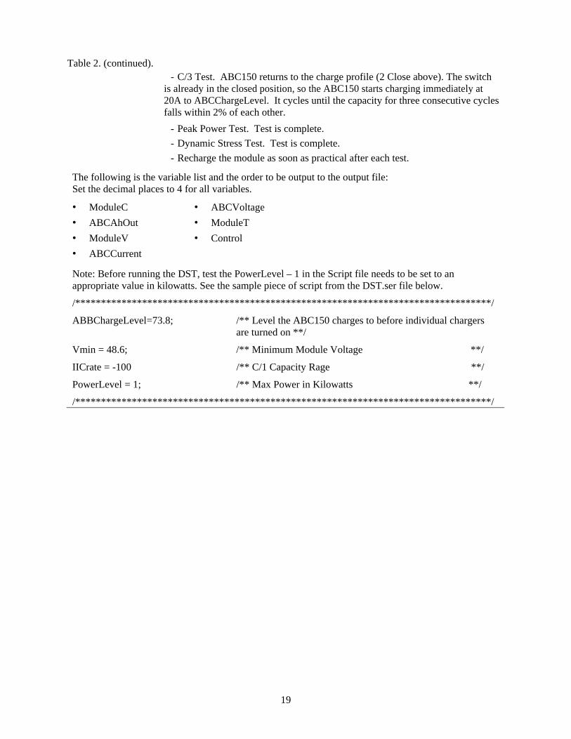
Table 2. (continued).
- C/3 Test. ABC150 returns to the charge profile (2 Close above). The switch is already in the closed position, so the ABC150 starts charging immediately at 20A to ABCChargeLevel. It cycles until the capacity for three consecutive cycles falls within 2% of each other.
- Peak Power Test. Test is complete. - Dynamic Stress Test. Test is complete. - Recharge the module as soon as practical after each test.
The following is the variable list and the order to be output to the output file: Set the decimal places to 4 for all variables.
• ModuleC • ABCVoltage • ABCAhOut • ModuleT • ModuleV • Control • ABCCurrent
Note: Before running the DST, test the PowerLevel – 1 in the Script file needs to be set to an appropriate value in kilowatts. See the sample piece of script from the DST.ser file below.
/*********************************************************************************/
ABBChargeLevel=73.8; /** Level the ABC150 charges to before individual chargers are turned on **/
Vmin = 48.6; /** Minimum Module Voltage **/
IICrate = -100 /** C/1 Capacity Rage **/
PowerLevel = 1; /** Max Power in Kilowatts **/
/*********************************************************************************/
19

Appendix A
Vehicle Photographs
20
Appendix A Vehicle Photographs
Figure A-1. Right quarter vehicle view.
Figure A-2. Front vehicle view.
21
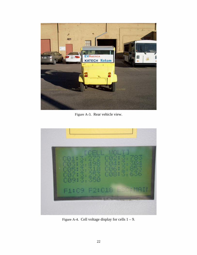
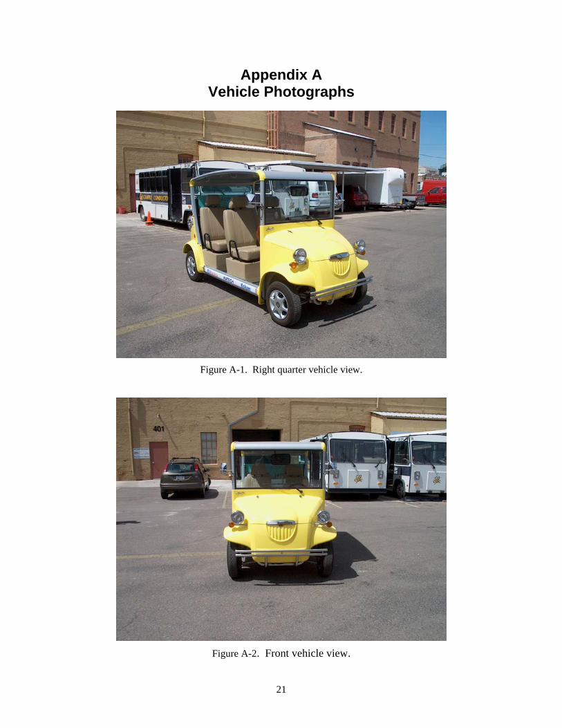
Figure A-3. Rear vehicle view.
Figure A-4. Cell voltage display for cells 1 – 9.
22
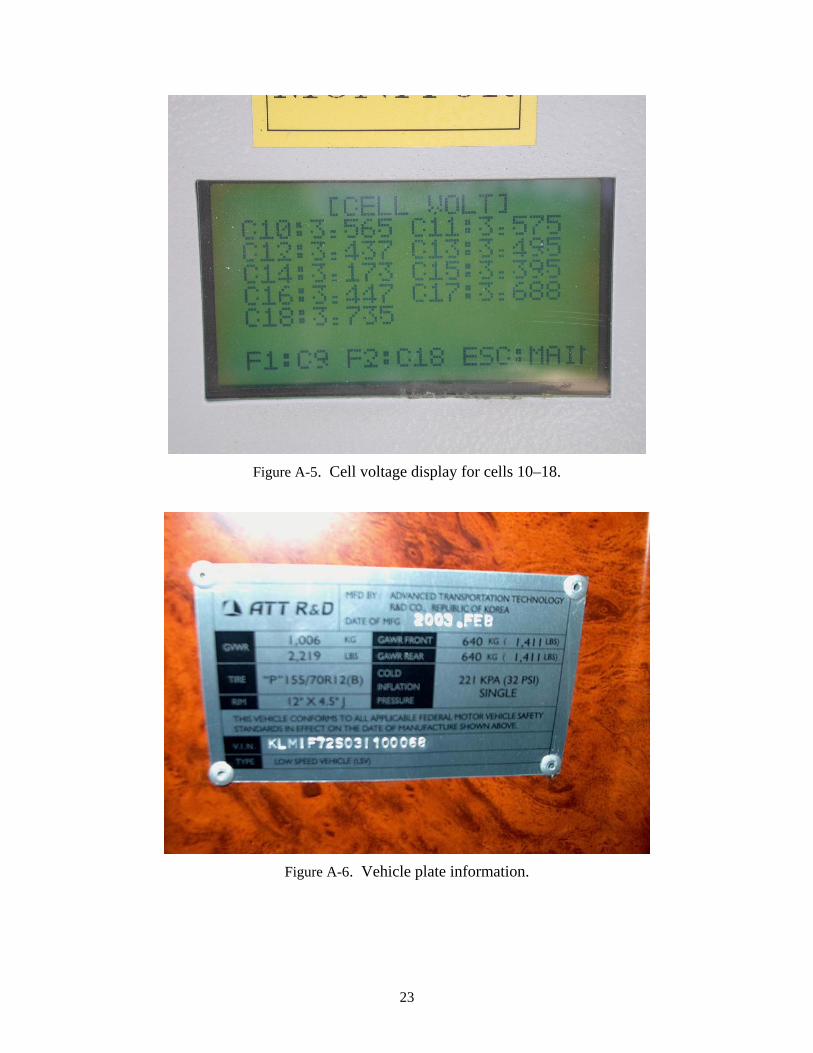
Figure A-5. Cell voltage display for cells 10–18.
Figure A-6. Vehicle plate information.
23
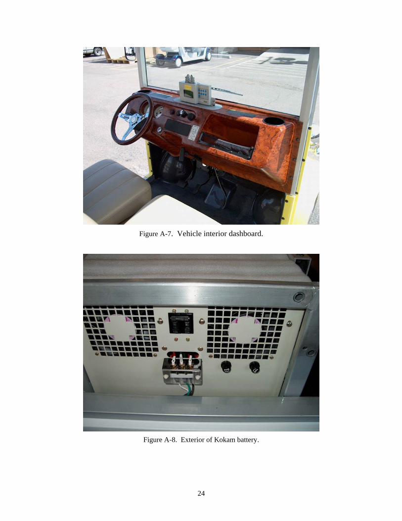
Figure A-7. Vehicle interior dashboard.
Figure A-8. Exterior of Kokam battery.
24
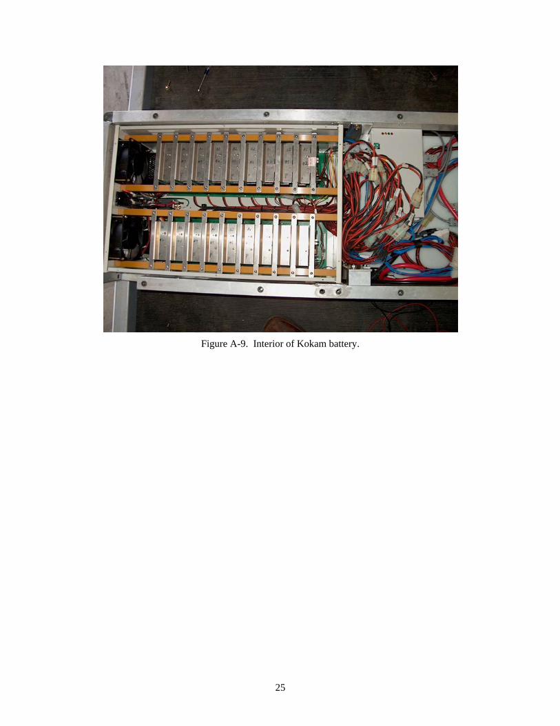
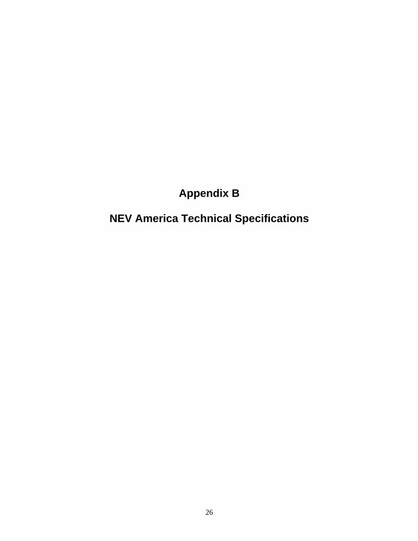
Figure A-9. Interior of Kokam battery.
25
Appendix B
NEV America Technical Specifications
26
Appendix B
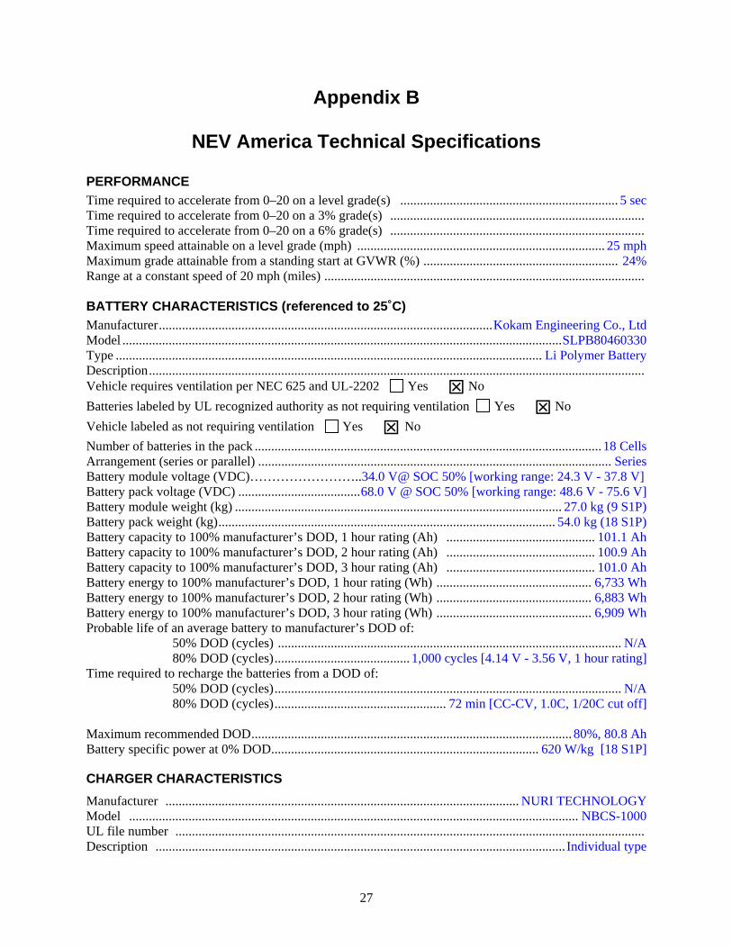
NEV America Technical Specifications
PERFORMANCE Time required to accelerate from 0–20 on a level grade(s) .................................................................. 5 sec Time required to accelerate from 0–20 on a 3% grade(s) ............................................................................. Time required to accelerate from 0–20 on a 6% grade(s) ............................................................................. Maximum speed attainable on a level grade (mph) ........................................................................... 25 mph Maximum grade attainable from a standing start at GVWR (%) ........................................................... 24% Range at a constant speed of 20 mph (miles) ................................................................................................. BATTERY CHARACTERISTICS (referenced to 25˚C) Manufacturer.....................................................................................................Kokam Engineering Co., Ltd Model .....................................................................................................................................SLPB80460330 Type ................................................................................................................................. Li Polymer Battery Description...................................................................................................................................................... Vehicle requires ventilation per NEC 625 and UL-2202 Yes No Batteries labeled by UL recognized authority as not requiring ventilation Yes No Vehicle labeled as not requiring ventilation Yes No Number of batteries in the pack ......................................................................................................... 18 Cells Arrangement (series or parallel) ........................................................................................................... Series Battery module voltage (VDC)……………………..34.0 V@ SOC 50% [working range: 24.3 V - 37.8 V] Battery pack voltage (VDC) .....................................68.0 V @ SOC 50% [working range: 48.6 V - 75.6 V] Battery module weight (kg) ................................................................................................... 27.0 kg (9 S1P) Battery pack weight (kg)...................................................................................................... 54.0 kg (18 S1P) Battery capacity to 100% manufacturer’s DOD, 1 hour rating (Ah) ............................................. 101.1 Ah Battery capacity to 100% manufacturer’s DOD, 2 hour rating (Ah) ............................................. 100.9 Ah Battery capacity to 100% manufacturer’s DOD, 3 hour rating (Ah) ............................................. 101.0 Ah Battery energy to 100% manufacturer’s DOD, 1 hour rating (Wh) ............................................... 6,733 Wh Battery energy to 100% manufacturer’s DOD, 2 hour rating (Wh) ............................................... 6,883 Wh Battery energy to 100% manufacturer’s DOD, 3 hour rating (Wh) ............................................... 6,909 Wh Probable life of an average battery to manufacturer’s DOD of:
50% DOD (cycles) ........................................................................................................ N/A 80% DOD (cycles)......................................... 1,000 cycles [4.14 V - 3.56 V, 1 hour rating]
Time required to recharge the batteries from a DOD of: 50% DOD (cycles)......................................................................................................... N/A 80% DOD (cycles).................................................... 72 min [CC-CV, 1.0C, 1/20C cut off]
Maximum recommended DOD................................................................................................. 80%, 80.8 Ah Battery specific power at 0% DOD................................................................................. 620 W/kg [18 S1P]
CHARGER CHARACTERISTICS
Manufacturer ........................................................................................................... NURI TECHNOLOGY Model ........................................................................................................................................ NBCS-1000 UL file number .............................................................................................................................................. Description ............................................................................................................................ Individual type
27
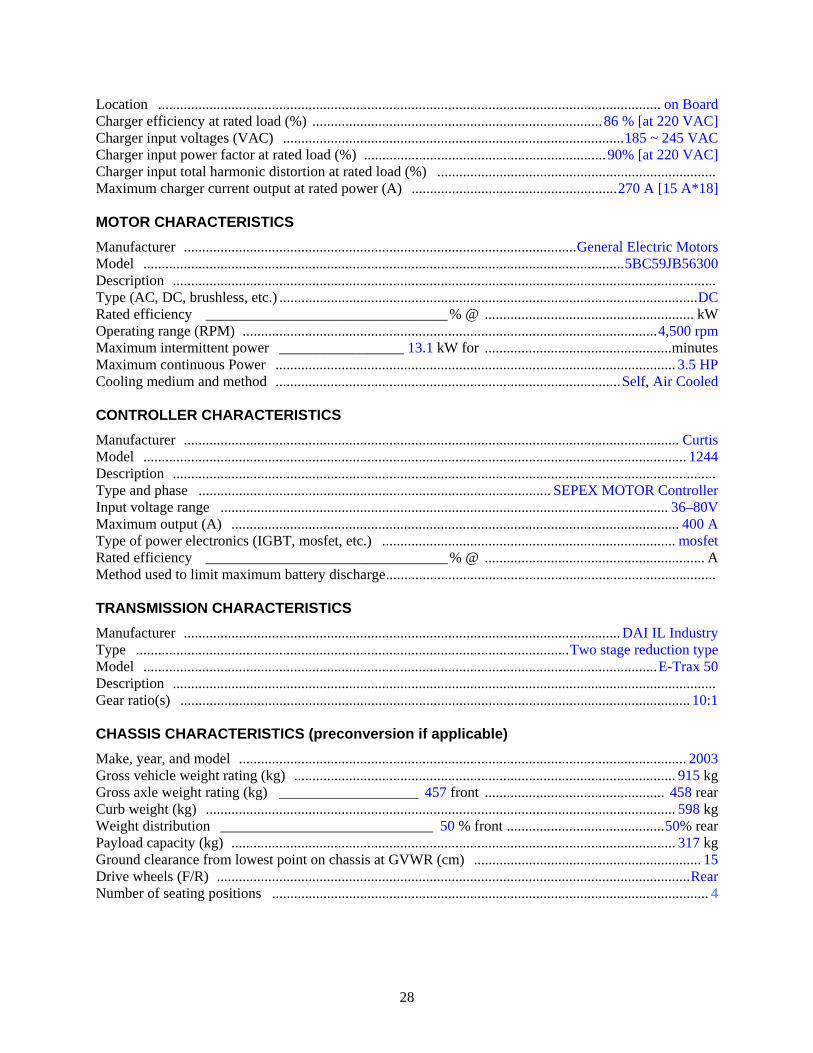
Location ......................................................................................................................................... on Board Charger efficiency at rated load (%) ...............................................................................86 % [at 220 VAC] Charger input voltages (VAC) .............................................................................................185 ~ 245 VAC Charger input power factor at rated load (%) ..................................................................90% [at 220 VAC] Charger input total harmonic distortion at rated load (%) ............................................................................ Maximum charger current output at rated power (A) ........................................................270 A [15 A*18] MOTOR CHARACTERISTICS
Manufacturer ...........................................................................................................General Electric Motors Model ...................................................................................................................................5BC59JB56300 Description .................................................................................................................................................... Type (AC, DC, brushless, etc.) ..................................................................................................................DC Rated efficiency _________________________________% @ ......................................................... kW Operating range (RPM) .................................................................................................................4,500 rpm Maximum intermittent power _________________ 13.1 kW for ...................................................minutes Maximum continuous Power ............................................................................................................. 3.5 HP Cooling medium and method ..............................................................................................Self, Air Cooled CONTROLLER CHARACTERISTICS
Manufacturer ....................................................................................................................................... Curtis Model .................................................................................................................................................... 1244 Description .................................................................................................................................................... Type and phase ................................................................................................ SEPEX MOTOR Controller Input voltage range .......................................................................................................................... 36–80V Maximum output (A) .......................................................................................................................... 400 A Type of power electronics (IGBT, mosfet, etc.) ................................................................................ mosfet Rated efficiency _________________________________% @ ............................................................ A Method used to limit maximum battery discharge.......................................................................................... TRANSMISSION CHARACTERISTICS Manufacturer ....................................................................................................................... DAI IL Industry Type ......................................................................................................................Two stage reduction type Model ............................................................................................................................................E-Trax 50 Description .................................................................................................................................................... Gear ratio(s) ........................................................................................................................................... 10:1 CHASSIS CHARACTERISTICS (preconversion if applicable) Make, year, and model .......................................................................................................................... 2003 Gross vehicle weight rating (kg) ........................................................................................................ 915 kg Gross axle weight rating (kg) ___________________ 457 front ................................................. 458 rear Curb weight (kg) ................................................................................................................................ 598 kg Weight distribution _____________________________ 50 % front ...........................................50% rear Payload capacity (kg) ......................................................................................................................... 317 kg Ground clearance from lowest point on chassis at GVWR (cm) .............................................................. 15 Drive wheels (F/R) .................................................................................................................................Rear Number of seating positions ....................................................................................................................... 4
28
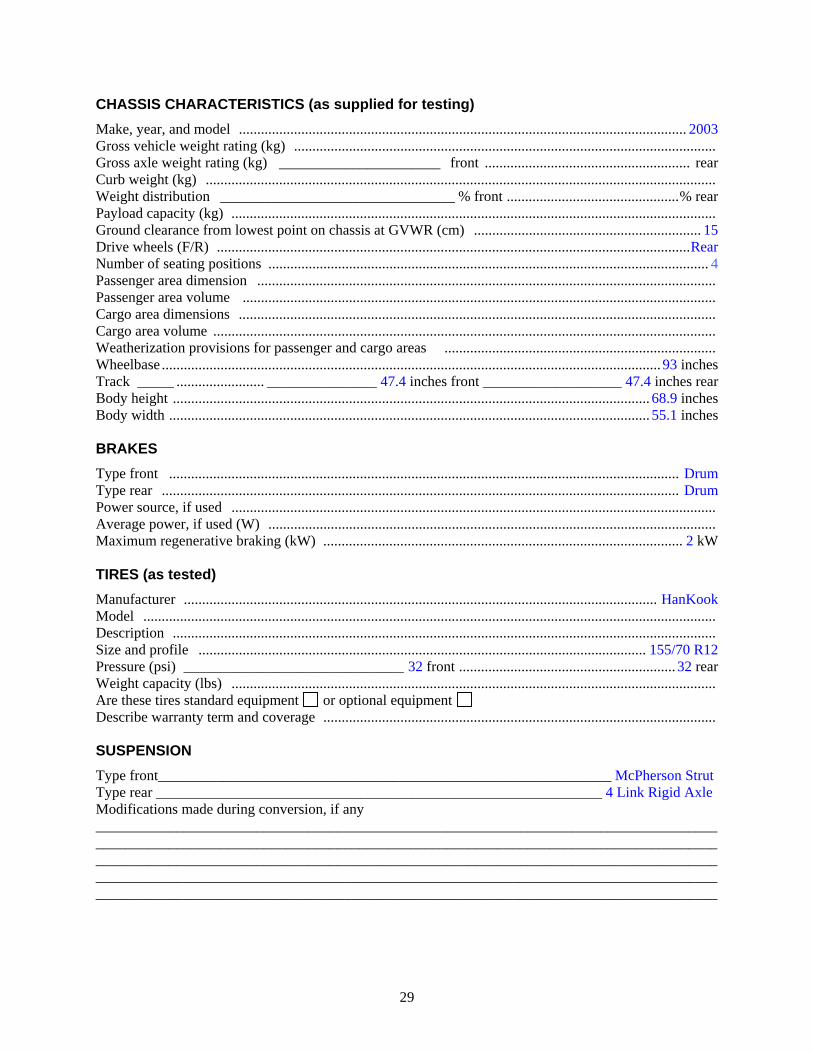
CHASSIS CHARACTERISTICS (as supplied for testing) Make, year, and model .......................................................................................................................... 2003 Gross vehicle weight rating (kg) ................................................................................................................... Gross axle weight rating (kg) ______________________ front ........................................................ rear Curb weight (kg) ........................................................................................................................................... Weight distribution ________________________________ % front ...............................................% rear Payload capacity (kg) .................................................................................................................................... Ground clearance from lowest point on chassis at GVWR (cm) .............................................................. 15 Drive wheels (F/R) .................................................................................................................................Rear Number of seating positions ........................................................................................................................ 4 Passenger area dimension ............................................................................................................................. Passenger area volume ................................................................................................................................. Cargo area dimensions .................................................................................................................................. Cargo area volume ......................................................................................................................................... Weatherization provisions for passenger and cargo areas .......................................................................... Wheelbase ........................................................................................................................................ 93 inches Track _____ ........................ _______________ 47.4 inches front ___________________ 47.4 inches rear Body height .................................................................................................................................. 68.9 inches Body width ................................................................................................................................... 55.1 inches BRAKES Type front ........................................................................................................................................... Drum Type rear ............................................................................................................................................. Drum Power source, if used .................................................................................................................................... Average power, if used (W) .......................................................................................................................... Maximum regenerative braking (kW) .................................................................................................. 2 kW TIRES (as tested) Manufacturer ................................................................................................................................. HanKook Model ............................................................................................................................................................ Description .................................................................................................................................................... Size and profile .......................................................................................................................... 155/70 R12 Pressure (psi) ______________________________ 32 front ........................................................... 32 rear Weight capacity (lbs) .................................................................................................................................... Are these tires standard equipment or optional equipment Describe warranty term and coverage ........................................................................................................... SUSPENSION
Type front______________________________________________________________ McPherson Strut Type rear _____________________________________________________________ 4 Link Rigid Axle Modifications made during conversion, if any _______________________________________________________________________________________________________________________________________________________________________________________________________________________________________________________________ __________________________________________________________________________________________________________________________________________________________________________
29
STEERING
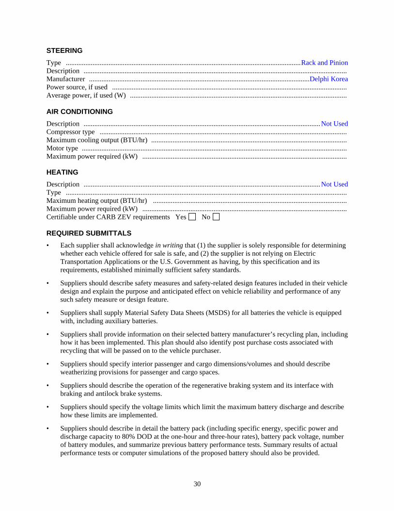
Type ....................................................................................................................................Rack and Pinion Description .................................................................................................................................................... Manufacturer ............................................................................................................................Delphi Korea Power source, if used .................................................................................................................................... Average power, if used (W) .......................................................................................................................... AIR CONDITIONING
Description ..................................................................................................................................... Not Used Compressor type ........................................................................................................................................... Maximum cooling output (BTU/hr) .............................................................................................................. Motor type ..................................................................................................................................................... Maximum power required (kW) ...................................................................................................................
HEATING
Description ..................................................................................................................................... Not Used Type .............................................................................................................................................................. Maximum heating output (BTU/hr) ............................................................................................................. Maximum power required (kW) ................................................................................................................... Certifiable under CARB ZEV requirements Yes No REQUIRED SUBMITTALS
• Each supplier shall acknowledge in writing that (1) the supplier is solely responsible for determining whether each vehicle offered for sale is safe, and (2) the supplier is not relying on Electric Transportation Applications or the U.S. Government as having, by this specification and its requirements, established minimally sufficient safety standards.
• Suppliers should describe safety measures and safety-related design features included in their vehicle design and explain the purpose and anticipated effect on vehicle reliability and performance of any such safety measure or design feature.
• Suppliers shall supply Material Safety Data Sheets (MSDS) for all batteries the vehicle is equipped with, including auxiliary batteries.
• Suppliers shall provide information on their selected battery manufacturer’s recycling plan, including how it has been implemented. This plan should also identify post purchase costs associated with recycling that will be passed on to the vehicle purchaser.
• Suppliers should specify interior passenger and cargo dimensions/volumes and should describe weatherizing provisions for passenger and cargo spaces.
• Suppliers should describe the operation of the regenerative braking system and its interface with braking and antilock brake systems.
• Suppliers should specify the voltage limits which limit the maximum battery discharge and describe how these limits are implemented.
• Suppliers should describe in detail the battery pack (including specific energy, specific power and discharge capacity to 80% DOD at the one-hour and three-hour rates), battery pack voltage, number of battery modules, and summarize previous battery performance tests. Summary results of actual performance tests or computer simulations of the proposed battery should also be provided.
30

• Suppliers should describe projected charge cycles at a specified level of discharge, how battery life is maximized, how end of life of each battery module and of the full battery pack is determined, and how battery temperature gradients are minimized.
• Suppliers shall indicate the depth of discharge below which the batteries should not be discharged. This should include the specific parameters the controller/inverter uses to prevent over discharge.
• Suppliers should describe how batteries are installed in the vehicle (including details of module connection), the method of installation and removal of the batteries (and the battery box, if required) for maintenance and repair, the time required for battery removal, and any special training, tools, or equipment required for battery removal.
• Suppliers shall provide verification of conformance to the requirements of Section 6.5 of UEV America Vehicle Technical Specification, Revision 2, January 1, 2003.
• Suppliers shall describe how battery boxes will be vented, to allow any battery gases to escape safely to atmosphere during and following normal or abnormal charging and operation of the vehicle. Suppliers shall provide a verification of conformance to SAE J1718 APR97 on Battery Gas Evolution.
• If a supplier provides a vehicle with parallel battery packs, the supplier should provide detailed information on the equipment and charging algorithms required to prevent the parallel strings from becoming unbalanced.
• Maintenance requirements for the propulsion batteries should be described and any associated cost(s) to the consumer/end user should be clearly defined.
• Suppliers should verify that the method(s) of charging and the charging algorithm(s) do not impact the battery warranties available to the end-user from either the vehicle supplier or the battery manufacturer, if the battery manufacturer warrants the battery.
• Suppliers should provide details on grounding and isolation methods.
• Suppliers should describe the type, size, and location of the point of the vehicle charging port.
• Suppliers should describe the following options, if available: - Passenger compartment heater - Air conditioning system - Occupant compartment preheating and precooling system - Cold weather range extension
• Vehicles shall be accompanied by nonproprietary manuals for parts, service, operation and maintenance, interconnection wiring diagrams, and schematics (with pricing for optional manuals).
31
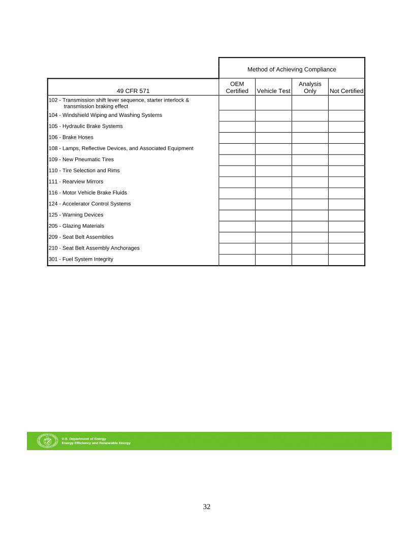
Method of Achieving Compliance
49 CFR 571
OEM Certified
Vehicle Test
Analysis Only
Not Certified
102 - Transmission shift lever sequence, starter interlock & transmission braking effect
104 - Windshield Wiping and Washing Systems 105 - Hydraulic Brake Systems 106 - Brake Hoses 108 - Lamps, Reflective Devices, and Associated Equipment 109 - New Pneumatic Tires 110 - Tire Selection and Rims 111 - Rearview Mirrors 116 - Motor Vehicle Brake Fluids 124 - Accelerator Control Systems 125 - Warning Devices 205 - Glazing Materials 209 - Seat Belt Assemblies 210 - Seat Belt Assembly Anchorages 301 - Fuel System Integrity
32