Embed Size (px)
Citation preview

Part 1
FCC Notes: This equipment generates, uses, and can radiate radio frequency energy and, if not installed and used in accordance with the instructions manual, may cause interference to radio communications. It has been tested and found to comply with limits for a Class A digital device pursuant to subpart J of Part 15 of FCC Rules, which are designed to provide reasonable protection against interference when operated in a commercial environment. Operation of this equipment in a residential area is likely to cause interference in which case the user at his own expense will be required to take whatever measures to correct the interference. Warranty Limits: Warranty terminates automatically when any person other than the authorized technicians opens the machine. The user should consult his/her dealer for the problem happened. Warranty voids if the user does not follow the instructions in application of this merchandise. The manufacturer is by no means responsible for any damage or hazard caused by improper application. About This Manual: Posiflex has made every effort for the accuracy of the content in this manual. However, Posiflex will assume no liability for any technical inaccuracies or editorial or other errors or omissions contained herein, nor for direct, indirect, incidental, consequential or otherwise damages, including without limitation loss of data or profits, resulting from the furnishing, performance, or use of this material. This information is provided “as is” and Posiflex Technologies, Inc. expressly disclaims any warranties, expressed, implied or statutory, including without limitation implied warranties of merchantability or fitness for particular purpose, good title and against infringement. The information in this manual contains only essential hardware concerns for general user and is subject to change without notice. Posiflex reserves the right to alter product designs, layouts or drivers without notification. The system integrator shall provide applicative notices and arrangement for special options utilizing this product. The user may find the most up to date information of the hardware from web sites: http://www.posiflex.com or http://www.posiflex.com.tw or http://www.posiflexusa.com All data should be backed-up prior to the installation of any drive unit or storage peripheral. Posiflex Technologies, Inc. will not be responsible for any loss of data resulting from the use, disuse or misuse of this or any other Posiflex product. All rights are strictly reserved. No part of this documentation may be reproduced, stored in a retrieval system, or transmitted in any form or by any means, electronic, mechanical, photocopying, or otherwise, without prior express written consent from Posiflex Technologies, Inc. the publisher of this documentation. © Copyright Posiflex Technologies, Inc. 2007 All brand and product names and trademarks are the property of their respective holders.
KB-4000 / KP-100 / SD-100 MULTIFUNCTION SECURITY DEVICE
USER’S MANUAL Rev.: C2
P/N: 19010900060
Part 2
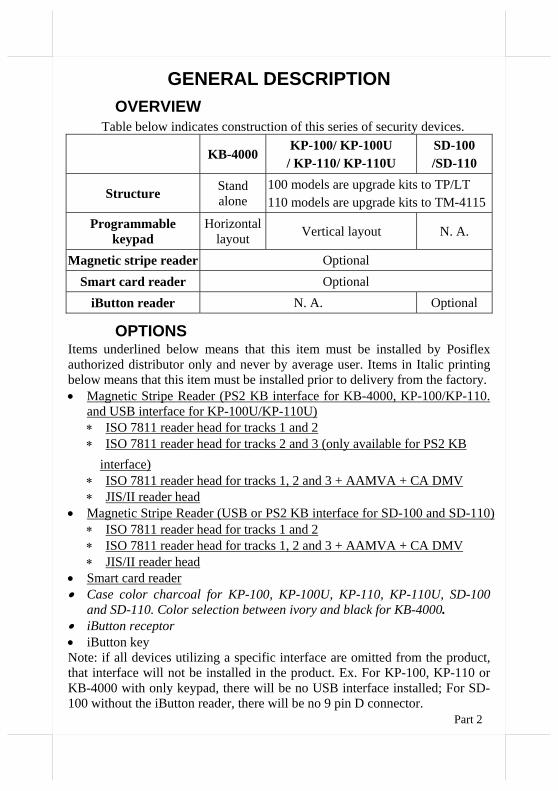
GENERAL DESCRIPTION OVERVIEW
Table below indicates construction of this series of security devices.
KB-4000KP-100/ KP-100U
/ KP-110/ KP-110U SD-100 /SD-110
Structure Stand alone
100 models are upgrade kits to TP/LT 110 models are upgrade kits to TM-4115
Programmable keypad
Horizontal layout Vertical layout N. A.
Magnetic stripe reader Optional
Smart card reader Optional iButton reader N. A. Optional
OPTIONS Items underlined below means that this item must be installed by Posiflex authorized distributor only and never by average user. Items in Italic printing below means that this item must be installed prior to delivery from the factory. • Magnetic Stripe Reader (PS2 KB interface for KB-4000, KP-100/KP-110.
and USB interface for KP-100U/KP-110U) ∗ ISO 7811 reader head for tracks 1 and 2 ∗ ISO 7811 reader head for tracks 2 and 3 (only available for PS2 KB
interface) ∗ ISO 7811 reader head for tracks 1, 2 and 3 + AAMVA + CA DMV ∗ JIS/II reader head
• Magnetic Stripe Reader (USB or PS2 KB interface for SD-100 and SD-110) ∗ ISO 7811 reader head for tracks 1 and 2 ∗ ISO 7811 reader head for tracks 1, 2 and 3 + AAMVA + CA DMV ∗ JIS/II reader head
• Smart card reader • Case color charcoal for KP-100, KP-100U, KP-110, KP-110U, SD-100
and SD-110. Color selection between ivory and black for KB-4000. • iButton receptor • iButton key Note: if all devices utilizing a specific interface are omitted from the product, that interface will not be installed in the product. Ex. For KP-100, KP-110 or KB-4000 with only keypad, there will be no USB interface installed; For SD-100 without the iButton reader, there will be no 9 pin D connector.
Part 3
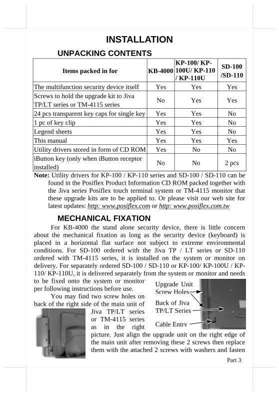
INSTALLATION UNPACKING CONTENTS
Items packed in for KB-4000KP-100/ KP-100U/ KP-110 / KP-110U
SD-100/SD-110
The multifunction security device itself Yes Yes Yes Screws to hold the upgrade kit to Jiva TP/LT series or TM-4115 series No Yes Yes
24 pcs transparent key caps for single key Yes Yes No 1 pc of key clip Yes Yes No Legend sheets Yes Yes No This manual Yes Yes Yes Utility drivers stored in form of CD ROM Yes No No iButton key (only when iButton receptor installed) No No 2 pcs
Note: Utility drivers for KP-100 / KP-110 series and SD-100 / SD-110 can be found in the Posiflex Product Information CD ROM packed together with the Jiva series Posiflex touch terminal system or TM-4115 monitor that these upgrade kits are to be applied to. Or please visit our web site for latest updates: http: www.posiflex.com or http: www.posiflex.com.tw
MECHANICAL FIXATION For KB-4000 the stand alone security device, there is little concern
about the mechanical fixation as long as the security device (keyboard) is placed in a horizontal flat surface not subject to extreme environmental conditions. For SD-100 ordered with the Jiva TP / LT series or SD-110 ordered with TM-4115 series, it is installed on the system or monitor on delivery. For separately ordered SD-100 / SD-110 or KP-100/ KP-100U / KP-110/ KP-110U, it is delivered separately from the system or monitor and needs to be fixed onto the system or monitor per following instructions before use.
You may find two screw holes on back of the right side of the main unit of
Jiva TP/LT series or TM-4115 series as in the right picture. Just align the upgrade unit on the right edge of the main unit after removing these 2 screws then replace them with the attached 2 screws with washers and fasten
Back of Jiva TP/LT Series
Upgrade Unit Screw Holes
Cable Entry
Part 4
them as indicated in the picture at above left.
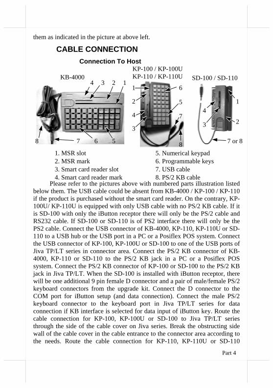
CABLE CONNECTION Connection To Host
Please refer to the pictures above with numbered parts illustration listed
below them. The USB cable could be absent from KB-4000 / KP-100 / KP-110 if the product is purchased without the smart card reader. On the contrary, KP-100U/ KP-110U is equipped with only USB cable with no PS/2 KB cable. If it is SD-100 with only the iButton receptor there will only be the PS/2 cable and RS232 cable. If SD-100 or SD-110 is of PS2 interface there will only be the PS2 cable. Connect the USB connector of KB-4000, KP-110, KP-110U or SD-110 to a USB hub or the USB port in a PC or a Posiflex POS system. Connect the USB connector of KP-100, KP-100U or SD-100 to one of the USB ports of Jiva TP/LT series in connector area. Connect the PS/2 KB connector of KB-4000, KP-110 or SD-110 to the PS/2 KB jack in a PC or a Posiflex POS system. Connect the PS/2 KB connector of KP-100 or SD-100 to the PS/2 KB jack in Jiva TP/LT. When the SD-100 is installed with iButton receptor, there will be one additional 9 pin female D connector and a pair of male/female PS/2 keyboard connectors from the upgrade kit. Connect the D connector to the COM port for iButton setup (and data connection). Connect the male PS/2 keyboard connector to the keyboard port in Jiva TP/LT series for data connection if KB interface is selected for data input of iButton key. Route the cable connection for KP-100, KP-100U or SD-100 to Jiva TP/LT series through the side of the cable cover on Jiva series. Break the obstructing side wall of the cable cover in the cable entrance to the connector area according to the needs. Route the cable connection for KP-110, KP-110U or SD-110
SD-100 / SD-110
1
2
4
3
7 or 8
KB-40001234
7 568
1. MSR slot 2. MSR mark 3. Smart card reader slot4. Smart card reader mark
5. Numerical keypad 6. Programmable keys 7. USB cable 8. PS/2 KB cable
1
2
3
4 7
5
6
8
KP-100 / KP-100UKP-110 / KP-110U
Part 5
through the cable cover area in similar manner and through the base of TM-4115 to the host PC or POS system.
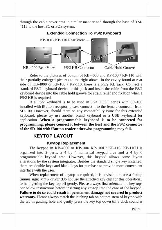
Extended Connection To PS/2 Keyboard
Refer to the pictures of bottom of KB-4000 and KP-100 / KP-110 with their partially enlarged pictures to the right above. In the cavity found at rear side of KB-4000 or KP-100 / KP-110, there is a PS/2 KB jack. Connect a standard PS/2 keyboard device to this jack and insert the cable from the PS/2 keyboard device into the cable hold groove for strain relief and fixation when a PS/2 KB is required.
If a PS/2 keyboard is to be used in Jiva TP/LT series with SD-100 installed with iButton receptor, please connect it to the female connector from SD-100. However, should there be any compatibility issue for this extended keyboard, please try use another brand keyboard or a USB keyboard for application. When a programmable keyboard is to be connected for programming, please connect it between the host and the PS/2 connector of the SD-100 with iButton reader otherwise programming may fail.
KEYTOP LAYOUT Keytop Replacement
The keypad in KB-4000 or KP-100/ KP-100U/ KP-110/ KP-110U is organized into 2 parts: a 4 by 4 numerical keypad area and a 4 by 6 programmable keypad area. However, this keypad allows some layout alterations by the system integrator. Besides the standard single key installed, there are double keys and blank keys for purchase to provide more convenient interface with the user.
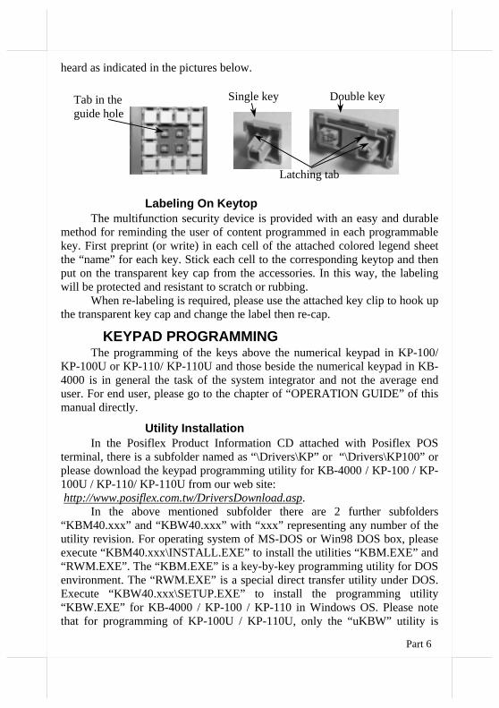
When replacement of keytop is required, it is advisable to use a flattop (minus sign) screw driver (Do not use the attached key clip for this operation.) to help getting the key top off gently. Please always first orientate the key tops per below instructions before inserting any keytop into the case of the keypad. Failure to do so could result in permanent damage not covered in product warranty. Please always match the latching tab on bottom stem of keytop with the tab in guiding hole and gently press the key top down till a click sound is
PS/2 KB Connector KB-4000 Rear View
KP-100 / KP-110 Rear View
Cable Hold Groove
Part 6
heard as indicated in the pictures below.
Labeling On Keytop The multifunction security device is provided with an easy and durable
method for reminding the user of content programmed in each programmable key. First preprint (or write) in each cell of the attached colored legend sheet the “name” for each key. Stick each cell to the corresponding keytop and then put on the transparent key cap from the accessories. In this way, the labeling will be protected and resistant to scratch or rubbing.
When re-labeling is required, please use the attached key clip to hook up the transparent key cap and change the label then re-cap.
KEYPAD PROGRAMMING The programming of the keys above the numerical keypad in KP-100/
KP-100U or KP-110/ KP-110U and those beside the numerical keypad in KB-4000 is in general the task of the system integrator and not the average end user. For end user, please go to the chapter of “OPERATION GUIDE” of this manual directly.
Utility Installation In the Posiflex Product Information CD attached with Posiflex POS
terminal, there is a subfolder named as “\Drivers\KP” or “\Drivers\KP100” or please download the keypad programming utility for KB-4000 / KP-100 / KP-100U / KP-110/ KP-110U from our web site: http://www.posiflex.com.tw/DriversDownload.asp.
In the above mentioned subfolder there are 2 further subfolders “KBM40.xxx” and “KBW40.xxx” with “xxx” representing any number of the utility revision. For operating system of MS-DOS or Win98 DOS box, please execute “KBM40.xxx\INSTALL.EXE” to install the utilities “KBM.EXE” and “RWM.EXE”. The “KBM.EXE” is a key-by-key programming utility for DOS environment. The “RWM.EXE” is a special direct transfer utility under DOS. Execute “KBW40.xxx\SETUP.EXE” to install the programming utility “KBW.EXE” for KB-4000 / KP-100 / KP-110 in Windows OS. Please note that for programming of KP-100U / KP-110U, only the “uKBW” utility is
Single key
Latching tab
Double key Tab in the guide hole
Part 7
applicable. Execute “uKBW_xxx\SETUP.EXE” to install the programming utility “uKBW.EXE”. After completion of the “Setup”, there will be a program group “Posiflex Tools” in the program files. Clicking the program “Posiflex Programmable Keyboard” in this group will activate the KBW.EXE for KB-4000 / KP-100 / KP-110. Clicking the program “Posiflex USB Programmable Keyboard” in this group will activate the uKBW.EXE for KP-100U / KP-110U.
Programming Preparation A normal keyboard may be required for inputting data in keypad
programming. If a PS/2 interface keyboard is to be used, please connect it to the extended PS/2 KB jack in the recessed cavity on back of KB-4000 / KP-100/ KP-110 as mentioned earlier. Please note that there must not be any other PS/2 device connected in between the KB-4000 / KP-100 / KP-110 and the PS/2 KB port of the host system in the keypad programming operation. For KP-100U/ KP-110U the normal keyboard can be connected to either the PS/2 KB port or an available USB port of the System according to the keyboard type.
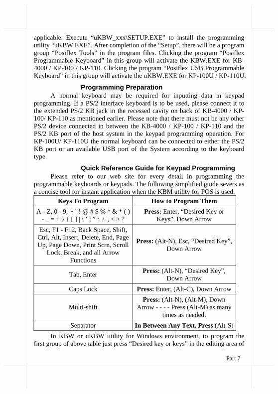
Quick Reference Guide for Keypad Programming Please refer to our web site for every detail in programming the
programmable keyboards or keypads. The following simplified guide severs as a concise tool for instant application when the KBM utility for POS is used.
Keys To Program How to Program Them A - Z, 0 - 9, ~ ` ! @ # $ % ^ & * ( )
- _ = + } { [ ] | \ ’ ; ” : /. , < > ? Press: Enter, “Desired Key or
Keys”, Down Arrow Esc, F1 - F12, Back Space, Shift, Ctrl, Alt, Insert, Delete, End, Page Up, Page Down, Print Scrn, Scroll
Lock, Break, and all Arrow Functions
Press: (Alt-N), Esc, “Desired Key”, Down Arrow
Tab, Enter Press: (Alt-N), “Desired Key”, Down Arrow
Caps Lock Press: Enter, (Alt-C), Down Arrow
Multi-shift Press: (Alt-N), (Alt-M), Down
Arrow - - - - Press (Alt-M) as many times as needed.
Separator In Between Any Text, Press (Alt-S)In KBW or uKBW utility for Windows environment, to program the
first group of above table just press “Desired key or keys” in the editing area of
Part 8
the selected key. To program the rest groups, please click the right button of mouse in the editing area and select from the pop-up menu. Please note that for KP-100U/ KP-110U, the “ Multi-Shift” and “Separator” are not applicable.
Hardware Limitation in Programming In case of “multiple combination key” application which means pressing
three or more keys at the same time to obtain certain data output from the keyboard, there could be some limitations inherent from the nature of keyboard structure. The CPU of keyboard detects the contact between the “horizontal” and “vertical” lines for each key press, recognizes which key is pressed and sends correspondent data to the host computer. When there are many keys pressed at the same time, and the pattern of the contacts coincides with some special relationship, there are chances that the CPU of keyboard be confused about exactly which keys are pressed. The system integrator may change the locations of the key-definition to prevent this once such confusion happens.
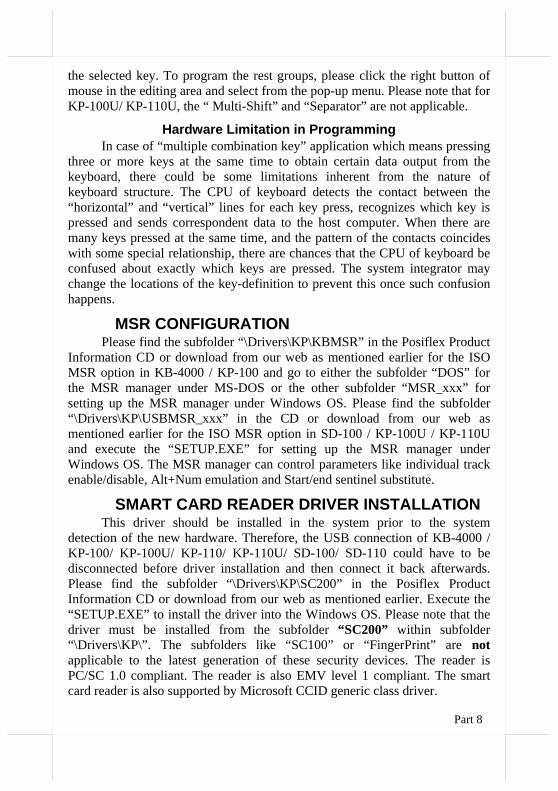
MSR CONFIGURATION Please find the subfolder “\Drivers\KP\KBMSR” in the Posiflex Product
Information CD or download from our web as mentioned earlier for the ISO MSR option in KB-4000 / KP-100 and go to either the subfolder “DOS” for the MSR manager under MS-DOS or the other subfolder “MSR_xxx” for setting up the MSR manager under Windows OS. Please find the subfolder “\Drivers\KP\USBMSR_xxx” in the CD or download from our web as mentioned earlier for the ISO MSR option in SD-100 / KP-100U / KP-110U and execute the “SETUP.EXE” for setting up the MSR manager under Windows OS. The MSR manager can control parameters like individual track enable/disable, Alt+Num emulation and Start/end sentinel substitute.
SMART CARD READER DRIVER INSTALLATION This driver should be installed in the system prior to the system
detection of the new hardware. Therefore, the USB connection of KB-4000 / KP-100/ KP-100U/ KP-110/ KP-110U/ SD-100/ SD-110 could have to be disconnected before driver installation and then connect it back afterwards. Please find the subfolder “\Drivers\KP\SC200” in the Posiflex Product Information CD or download from our web as mentioned earlier. Execute the “SETUP.EXE” to install the driver into the Windows OS. Please note that the driver must be installed from the subfolder “SC200” within subfolder “\Drivers\KP\”. The subfolders like “SC100” or “FingerPrint” are not applicable to the latest generation of these security devices. The reader is PC/SC 1.0 compliant. The reader is also EMV level 1 compliant. The smart card reader is also supported by Microsoft CCID generic class driver.
Part 9
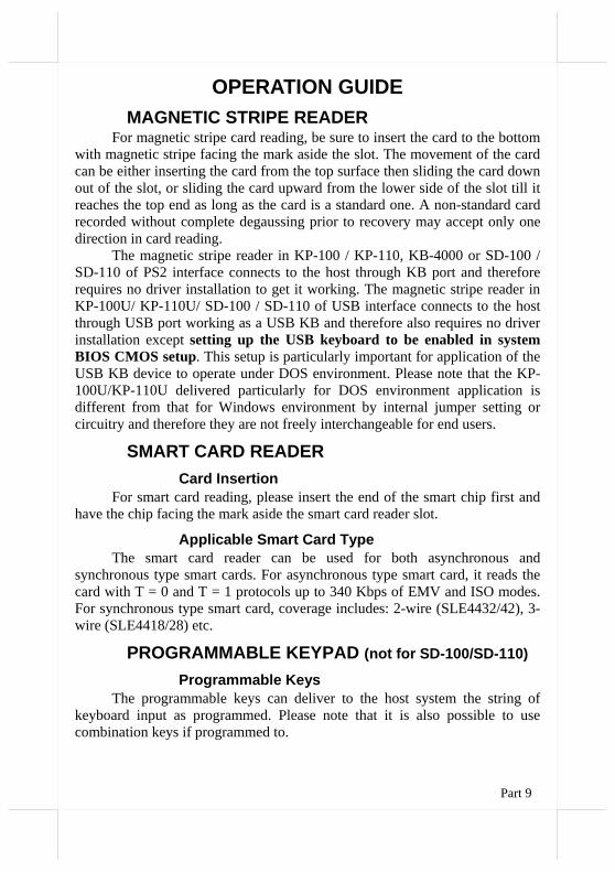
OPERATION GUIDE MAGNETIC STRIPE READER
For magnetic stripe card reading, be sure to insert the card to the bottom with magnetic stripe facing the mark aside the slot. The movement of the card can be either inserting the card from the top surface then sliding the card down out of the slot, or sliding the card upward from the lower side of the slot till it reaches the top end as long as the card is a standard one. A non-standard card recorded without complete degaussing prior to recovery may accept only one direction in card reading.
The magnetic stripe reader in KP-100 / KP-110, KB-4000 or SD-100 / SD-110 of PS2 interface connects to the host through KB port and therefore requires no driver installation to get it working. The magnetic stripe reader in KP-100U/ KP-110U/ SD-100 / SD-110 of USB interface connects to the host through USB port working as a USB KB and therefore also requires no driver installation except setting up the USB keyboard to be enabled in system BIOS CMOS setup. This setup is particularly important for application of the USB KB device to operate under DOS environment. Please note that the KP-100U/KP-110U delivered particularly for DOS environment application is different from that for Windows environment by internal jumper setting or circuitry and therefore they are not freely interchangeable for end users.
SMART CARD READER Card Insertion
For smart card reading, please insert the end of the smart chip first and have the chip facing the mark aside the smart card reader slot.
Applicable Smart Card Type The smart card reader can be used for both asynchronous and
synchronous type smart cards. For asynchronous type smart card, it reads the card with T = 0 and T = 1 protocols up to 340 Kbps of EMV and ISO modes. For synchronous type smart card, coverage includes: 2-wire (SLE4432/42), 3-wire (SLE4418/28) etc., SDA/I2C, 4403, 4433, 4404, 896
PROGRAMMABLE KEYPAD (not for SD-100/SD-110)
Programmable Keys The programmable keys can deliver to the host system the string of
keyboard input as programmed. Please note that it is also possible to use combination keys if programmed to.
Part 10
Numerical Keypad The numerical keypad is durably pre-marked. The numerical keypad is
not applicable in combination keys.
DOS Application Notice for KP-100U / KP-110U The keypad KP-100U/ KP-110U connects to the host through USB port
working as a USB KB and therefore also requires no driver installation except setting up the USB keyboard to be enabled in system BIOS CMOS setup. This setup is particularly important for application of the USB KB device to operate under DOS environment. Please note that the KP-100U / KP-110U delivered particularly for DOS environment application is different from that for Windows environment by internal jumper setting or circuitry and therefore they are not freely interchangeable for end users.
IBUTTON RECEPTOR (SD-100/SD-110 only) The iButton option can be programmed to communicate on either RS232
interface or PS/2 KB interface through Hyper Terminal configuration setup. Please refer to instruction on our web site for the detail. In general, this should be taken care of by the software in the way organized by the system integrator.
Each iButton receptor is delivered with 2 iButton keys attached. Each iButton key carries unique ID. Please approach your dealer for any additional iButton key required.
警告使用者 這是甲類的資訊產品,在居住的環
境中使用時,可能會造成射頻干
擾,在這種情況下,使用者會被要
求採取某些適當的對策。
T31454