Embed Size (px)
Citation preview
KBL1xxx Motor Controller Datasheet 1
KBL1xxx
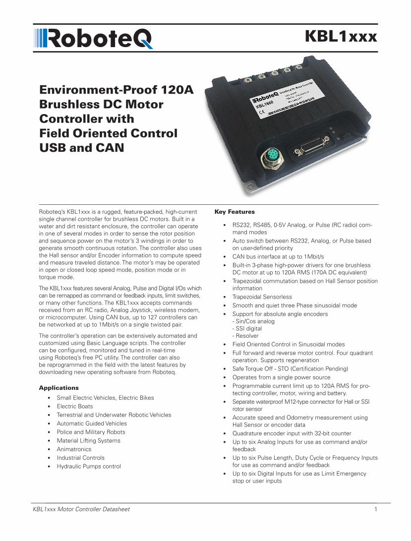
Roboteq’s KBL1xxx is a rugged, feature-packed, high-current single channel controller for brushless DC motors. Built in a water and dirt resistant enclosure, the controller can operate in one of several modes in order to sense the rotor position and sequence power on the motor’s 3 windings in order to generate smooth continuous rotation. The controller also uses the Hall sensor and/or Encoder information to compute speed and measure traveled distance. The motor’s may be operated in open or closed loop speed mode, position mode or in torque mode.
The KBL1xxx features several Analog, Pulse and Digital I/Os which can be remapped as command or feedback inputs, limit switches, or many other functions. The KBL1xxx accepts commands received from an RC radio, Analog Joystick, wireless modem, or microcomputer. Using CAN bus, up to 127 controllers can be networked at up to 1Mbit/s on a single twisted pair.
The controller’s operation can be extensively automated and customized using Basic Language scripts. The controller can be configured, monitored and tuned in real-time using Roboteq’s free PC utility. The controller can also be reprogrammed in the field with the latest features by downloading new operating software from Roboteq.
Applications
• Small Electric Vehicles, Electric Bikes• Electric Boats• Terrestrial and Underwater Robotic Vehicles• Automatic Guided Vehicles• Police and Military Robots• Material Lifting Systems• Animatronics• Industrial Controls• Hydraulic Pumps control
Key Features
• RS232, RS485, 0-5V Analog, or Pulse (RC radio) com-mand modes
• Auto switch between RS232, Analog, or Pulse based on user-defined priority
• CAN bus interface at up to 1Mbit/s• Built-in 3-phase high-power drivers for one brushless
DC motor at up to 120A RMS (170A DC equivalent)• Trapezoidal commutation based on Hall Sensor position
information• Trapezoidal Sensorless• Smooth and quiet three Phase sinusoidal mode • Support for absolute angle encoders
- Sin/Cos analog - SSI digital - Resolver
• Field Oriented Control in Sinusoidal modes • Full forward and reverse motor control. Four quadrant
operation. Supports regeneration• Safe Torque Off - STO (Certification Pending)• Operates from a single power source• Programmable current limit up to 120A RMS for pro-
tecting controller, motor, wiring and battery.• Separate waterproof M12-type connector for Hall or SSI
rotor sensor• Accurate speed and Odometry measurement using
Hall Sensor or encoder data• Quadrature encoder input with 32-bit counter• Up to six Analog Inputs for use as command and/or
feedback• Up to six Pulse Length, Duty Cycle or Frequency Inputs
for use as command and/or feedback• Up to six Digital Inputs for use as Limit Emergency
stop or user inputs
Environment-Proof 120ABrushless DC MotorController withField Oriented ControlUSB and CAN

2 KBL1xxx Motor Controller Datasheet Version 1.9 May 24, 2018
Orderable Product References
Reference Number of Channels Amps/Channel Volts FOC
KBL1660 1 120 60 Yes
• Two general purpose 40V, 1.5A output for brake release or accessories
• Custom scripting in Basic language. Execution speed 50000 lines per second
• Selectable min, max, center and deadband in Pulse and Analog modes
• Selectable exponentiation factors for each command inputs
• Trigger action if Analog, Pulse, Encoder or Hall counter capture are outside user selectable range (soft limit switches)
• Open loop or closed loop speed control operation• Closed loop position control with encoder, analog or
pulse/frequency feedback• PID control loop• Support for CANopen and two simplified CAN protocols• Configurable Data Logging of operating parameters on
RS232 Output for telemetry or analysis• Built-in Battery Voltage and Temperature sensors• Optional 12V backup power input for powering safely
the controller if the main motor batteries are discharged• Power Control wire for turning On or Off the controller
from external microcomputer or switch• No consumption by output stage when motors stopped• Regulated 5V output for powering encoders, sensors,
joysticks, RC radio, RF Modem or microcomputer
• Separate Programmable acceleration and deceleration for each motor
• Ultra-efficient 1.0 mOhm ON resistance MOSFETs• Auto stop if no motion is detected• Stall detection and selectable triggered action if Amps
is outside user-selected range• Short circuit protection with selectable sensitivity levels• Overvoltage and Undervoltage protection• Watchdog for automatic motor shutdown in case of
command loss• Overtemperature protection• Diagnostic LEDs• Efficient heat sinking using conduction bottom plate.
Operates without a fan in most application• Dust-proof and water-tight IP65 enclosure and connectors• Power wiring via heavy duty M4 terminals terminals• 5.50” (140mm) L, 4.45” W (113mm), 1.14” (29mm) H• -40o to +85o C operating environment• 440 g (0.96 lbs)• Easy configuration, tuning and monitor using provided
PC utility• Field upgradeable software for installing latest features
via the Internet

Power Wires Identifications and Connection
KBL1xxx Motor Controller Datasheet 3
Important Safety DisclaimerDangerous uncontrolled motor runaway condition can occur for a number of reasons, including, but not limited to: command or feedback wiring failure, configuration error, faulty firmware, errors in user script or user program, or controller hardware failure.
The user must assume that such failures can occur and must make their system safe in all conditions. Roboteq will not be liable in case of damage or injury as a result of product misuse or failure.
Power Wires Identifications and ConnectionPower connections are made through high current screw terminals. A waterproof 8-pin M12 female connector provides connection to Hall or SSI rotor sensor. Communication and user I/O are located on the DSub15 connector.
PwC VMOT U V W GND
STOEnable
PowerControl
Battery+ GND
USB
PowerStatus& COMLEDs
MotorSensors
I/O & Communication
Motor Connections
FIGURE 1. KBL1xxx Top View

4 KBL1xxx Motor Controller Datasheet Version 1.9 May 24, 2018
Figure 2, below, shows how to wire the controller and how to turn power On and Off.
Motor
RotorSensorsVMot
PwrCtrl
SW1 Main On/Off Switch 1A
F21A
Diode>20A
Resistor1K, 0.5W
+ -
SW2EmergencyContactor orCut-off Switch
F1
U
V
W
Hall/SSISinCosor Resolver
ConnectorSensors
I/O Connector
Ground
Ground
MainBattery
BackupBattery
Note 5 Do not Connect!
Note 1
2 etoN 3 etoN
U
V W
Note 4
FIGURE 2. Powering the Controller. Thick lines identify MANDATORY connections
Important Warning
Carefully follow the wiring instructions provided in the Power Connection section of the User Manual. The information on this datasheet is only a summary.
Mandatory ConnectionsIt is imperative that the controller is connected as shown in the above diagram in order to ensure a safe and trouble-free operation. All connections shown as thick black lines line are mandatory. The controller must be powered On/Off using switch SW1on the Power Control tab. Use a suitable high-current fuse F1 as a safety measure to prevent damage to the wiring in case of major controller malfunction.
Emergency Switch or ContactorThe battery must be connected in permanence to the controller’s VMot terminal via a high-power emergency switch or contactor SW2 as additional safety measure. The user must be able to deactivate the switch or con-tactor at anytime, independently of the controller state.
Precautions and Optional ConnectionsNote 1: Backup battery to ensure motor operation with weak or discharged batteries, connect a second battery to the Power Control wire/terminal via the SW1 switch.
Note 2: Use precharge 1K, 0.5W Resistor to prevent switch arcing.
Note 3: Insert a high-current diode to ensure a return path to the battery during regeneration in case the fuse is blown.
Motor Sensor Connector
KBL1xxx Motor Controller Datasheet 5
Note 4: Optionally ground the VMot input when the controller is Off if there is any concern that the motors could be made to spin and generate voltage in excess of the controller’s absolute max voltage rating.
Note 5: Beware not to create a path from the ground pins on the I/O connector and the battery minus terminal.
Controller MountingDuring motor operation, the controller will generate heat that must be dissipated. The published amps rating can only be fully achieved if adequate cooling is provided. Good conduction cooling can be achieved by mount-ing the controller to a metallic surface, such as the chassis, cabinet, etc.
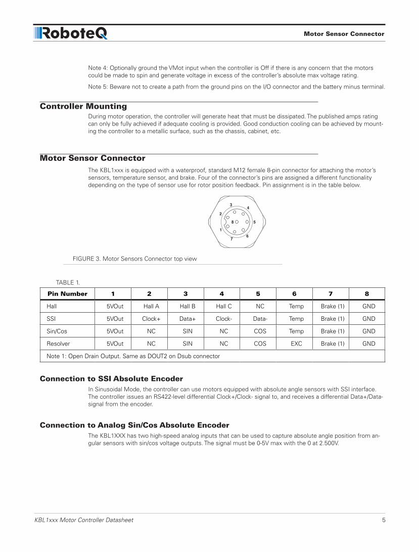
Motor Sensor ConnectorThe KBL1xxx is equipped with a waterproof, standard M12 female 8-pin connector for attaching the motor’s sensors, temperature sensor, and brake. Four of the connector’s pins are assigned a different functionality depending on the type of sensor use for rotor position feedback. Pin assignment is in the table below.
FIGURE 3. Motor Sensors Connector top view
TABLE 1.
Pin Number 1 2 3 4 5 6 7 8
Hall 5VOut Hall A Hall B Hall C NC Temp Brake (1) GND
SSI 5VOut Clock+ Data+ Clock- Data- Temp Brake (1) GND
Sin/Cos 5VOut NC SIN NC COS Temp Brake (1) GND
Resolver 5VOut NC SIN NC COS EXC Brake (1) GND
Note 1: Open Drain Output. Same as DOUT2 on Dsub connector
Connection to SSI Absolute EncoderIn Sinusoidal Mode, the controller can use motors equipped with absolute angle sensors with SSI interface. The controller issues an RS422-level differential Clock+/Clock- signal to, and receives a differential Data+/Data- signal from the encoder.
Connection to Analog Sin/Cos Absolute EncoderThe KBL1XXX has two high-speed analog inputs that can be used to capture absolute angle position from an-gular sensors with sin/cos voltage outputs. The signal must be 0-5V max with the 0 at 2.500V.

6 KBL1xxx Motor Controller Datasheet Version 1.9 May 24, 2018
Connecting ResolverResolver wiring is similar to a Sin/Cos sensor with the addition of an excitation signal. Diagram below shows the necessary connections.
Primary
Secondary 1 ASIN
ACOS
EXC
GNDSecondary 2
FIGURE 4. Resolver wiring
Commands and I/O ConnectionsConnection to RC Radio, Microcomputer, Joystick and other low current sensors and actuators is done via the 15-pin connector located in front of the controller. The functions of many pins vary depending on controller model and user configuration. Pin assignments are found in Table 2, below.
18
915
FIGURE 5. Connector Pin Locations
TABLE 2.
Connector Pin Power Dout Com RC Ana Dinput Enc Default Config
1 DOUT1 (1) Unused 9 DOUT2 (1)(6) Brake2 TxOut RS232Tx 10 RC ANA5 DIN5/STO1 (6) AnaCmd (3) 3 RxIn RS232Rx 11 485- RC4 ANA4 DIN4 Unused
4 RC1 ANA1 DIN1 ENCA (2) RCRadio1 12 485+ RC3 ANA3 DIN3 Unused5 GND 13 GND6 CANL CAN Low 14 5VOut7 CANH CAN High 15 RC6 ANA6 DIN6/STO2 (6) Unused8 RC2 ANA2 DIN2 ENCB (2) Unused
Note 1: Outputs are Open Drain. They pull to ground when on and float when off. Load must be connected between output and positive voltage.Note 2: Encoder input requires RC inputs 1 and 2 to be disabled. Encoder is disabled in factory default.Note 3: Analog command is disabled in factory default configuration.Note 5: Remove STO Jumper to enable Safe Torque Off functionalityNote 6: DOUT2 is replicated on the M12 connector

Motor Sensor Connector
KBL1xxx Motor Controller Datasheet 7
For use in environments where liquid particles or fine dust may present, the controller’s cover is shaped for DSub connectors with waterproof hoods. Product references EDAC 627-230-015-010 or Assmann A-DS15-HOOD-WP.
FIGURE 6. dsub15 waterproof shell
Default I/O ConfigurationThe controller can be configured so that practically any Digital, Analog and RC pin can be used for any purpose. The controller’s factory default configuration provides an assignment that is suitable for most applications.
The figure below shows how to wire the controller to an analog potentiometer, an RC radio, the RS232 port, and the Digital output to a motor brake solenoid. You may omit any connection that is not required in your ap-plication. The controller automatically arbitrates the command priorities depending on the presence of a valid command signal in the following order: 1-Serial, 2-RC Pulse, 3-None. If needed, use the Roborun+ PC Utility to change the pin assignments and the command priority order.
18
915
1
Pot
RS232
Brake ReleaseSafety Contactor
GroundTxOutRxIn
RC Ch1
FIGURE 7. Factory Default Pins Assignment

8 KBL1xxx Motor Controller Datasheet Version 1.9 May 24, 2018
Enabling Analog CommandsFor safety reasons, the Analog command mode is disabled by default. To enable the Analog mode, use the PC utility and set Analog in Command Priority 2 or 3 (leave Serial as priority 1). Note that by default the additional securities are enabled and will prevent the motor from starting unless the potentiometer is centered, or if the voltage is below 0.25V or above 4.75V. The drawing shows suggested assignment of Pot 1 to ANA1. Use the PC utility to enable and assign analog inputs.
CAN Bus OperationThe controller can interface to a standard CAN Bus network, using 4 possible protocols: Standard CANOpen, and three proprietary schemes (MiniCAN, RawCAN and RoboCAN). Please refer to the User Manual for details.
USB communicationUse USB only for configuration, monitoring and troubleshooting. USB is not a reliable communication method when used in a electrically noisy environments and communication will not always recover after it is lost with-out unplugging and replugging the connector, or restarting the controller. Always prefer RS232 communication when interfacing to a computer.
Status LEDs and Flashing PatternsThe controller is equipped with three LEDs. A Green Power LED, a Red/Green Status LED and a Yellow Com-munication LED.
After the controller is powered on, the Power LED will tun on, indicating that the controller is On. The Status LED will be flashing at a two second interval. The flashing pattern and color provides operating or exception status information.
RS232/USB Mode
Idle - Waiting for Command
RC Pulse Mode
Analog Mode
Under or Over Voltage
Power Stage Off
Short Detected
Overheat
FIGURE 8. Normal Operation Flashing Patterns
RS232/USB Mode
Idle - Waiting for Command
RC Pulse Mode
Analog Mode
Under or Over Voltage
Power Stage Off
Short Detected
Overheat
FIGURE 9. Exception or Fault Flashing Patterns
Safe Torque Off - STO (Certification Pending)
KBL1xxx Motor Controller Datasheet 9
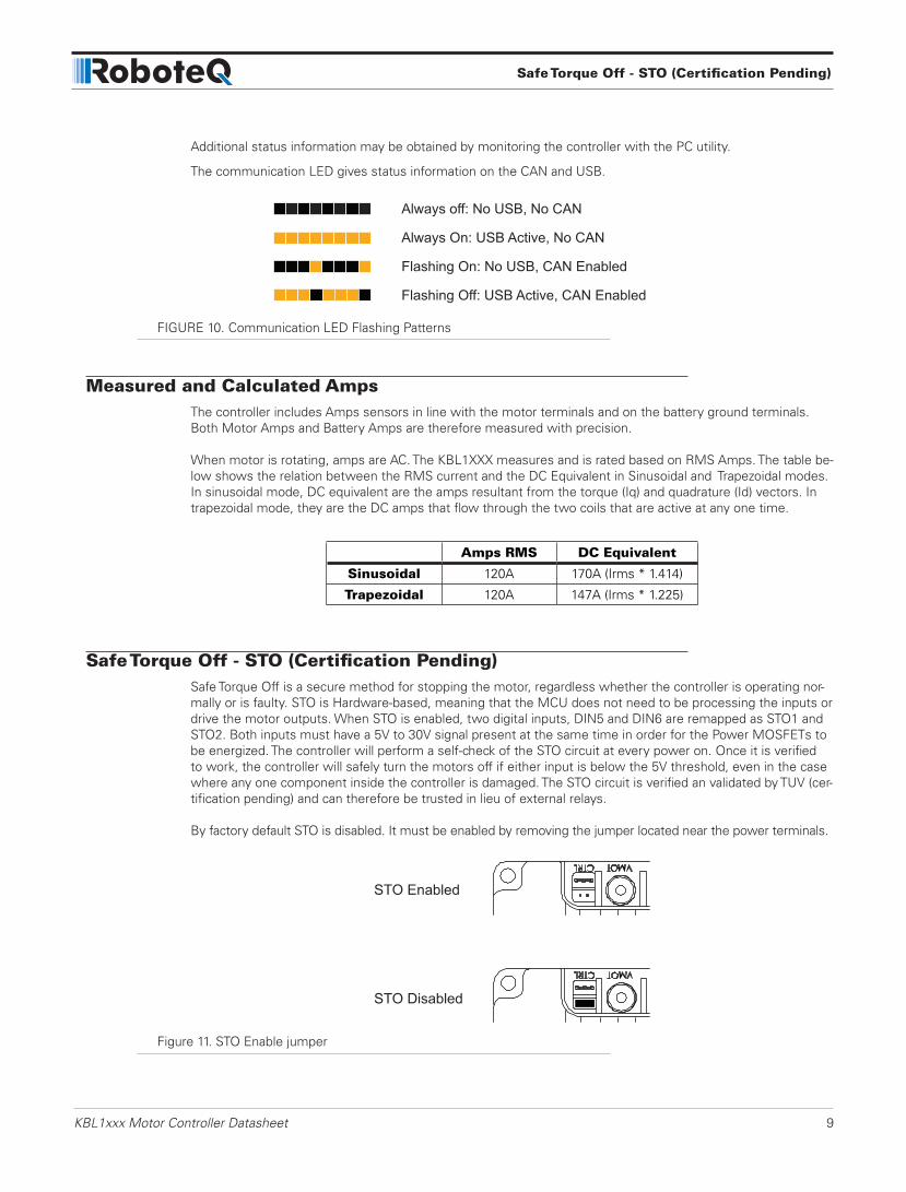
Additional status information may be obtained by monitoring the controller with the PC utility.
The communication LED gives status information on the CAN and USB.
Always off: No USB, No CAN
Always On: USB Active, No CAN
Flashing On: No USB, CAN Enabled
Flashing Off: USB Active, CAN Enabled
FIGURE 10. Communication LED Flashing Patterns
Measured and Calculated AmpsThe controller includes Amps sensors in line with the motor terminals and on the battery ground terminals. Both Motor Amps and Battery Amps are therefore measured with precision.
When motor is rotating, amps are AC. The KBL1XXX measures and is rated based on RMS Amps. The table be-low shows the relation between the RMS current and the DC Equivalent in Sinusoidal and Trapezoidal modes. In sinusoidal mode, DC equivalent are the amps resultant from the torque (Iq) and quadrature (Id) vectors. In trapezoidal mode, they are the DC amps that flow through the two coils that are active at any one time.
Amps RMS DC Equivalent
Sinusoidal 120A 170A (Irms * 1.414)
Trapezoidal 120A 147A (Irms * 1.225)
Safe Torque Off - STO (Certification Pending)Safe Torque Off is a secure method for stopping the motor, regardless whether the controller is operating nor-mally or is faulty. STO is Hardware-based, meaning that the MCU does not need to be processing the inputs or drive the motor outputs. When STO is enabled, two digital inputs, DIN5 and DIN6 are remapped as STO1 and STO2. Both inputs must have a 5V to 30V signal present at the same time in order for the Power MOSFETs to be energized. The controller will perform a self-check of the STO circuit at every power on. Once it is verified to work, the controller will safely turn the motors off if either input is below the 5V threshold, even in the case where any one component inside the controller is damaged. The STO circuit is verified an validated by TUV (cer-tification pending) and can therefore be trusted in lieu of external relays.
By factory default STO is disabled. It must be enabled by removing the jumper located near the power terminals.
STO Enabled
STO Disabled
Figure 11. STO Enable jumper

10 KBL1xxx Motor Controller Datasheet Version 1.9 May 24, 2018
Electrical Specifications
Absolute Maximum ValuesThe values in Table 3, below, should never be exceeded. Permanent damage to the controller may result.
TABLE 3.
Parameter Measure point Min Typ Max Units
Battery Leads Voltage Ground to VMot 62 Volts
Reverse Voltage on Battery Leads Ground to VMot -1 Volts
Power Control Voltage Ground to Pwr Control wire 62 Volts
Motor Leads Voltage Ground to U, V, W wires 62 (1) Volts
Digital Output Voltage Ground to Output pins 40 Volts
Analog and Digital Inputs Voltage Ground to any signal pin on 15-pin & Hall inputs
30 Volts
RS232 I/O pins Voltage External voltage applied to Rx/Tx pins
30 Volts
Case Temperature Case -40 85 ºC
Humidity Case 100 (2) %
Note 1: Maximum regeneration voltage in normal operation. Never inject a DC voltage from a battery or other fixed sourceNote 2: Non-condensing
Power Stage Electrical Specifications (at 25ºC ambient)
TABLE 4.
Parameter Measure point Min Typ Max Units
Battery Leads Voltage Ground to VMot 0 (1) 62 Volts
Motor Leads Voltage Ground to U, V, W wires 0 (1) 62 (2) Volts
Power Control Voltage 0 (1) 65 Volts
Minimum Operating Voltage 9 (3) Volts
Over Voltage protection range Ground to VMot 5 60 (4) 62 Volts
Under Voltage protection range Ground to VMot 0 5 (4) 62 Volts
Idle Current Consumption VMot or Pwr Ctrl wires 50 100 (5) 150 mA
ON Resistance (Excluding wire resis-tance)
VMot to U, V or W. Ground to U, V or W
1.5 mOhm
Max Current for 60s Motor current 120 (6) Amps
Continuous Max Current per channel Motor current 100 (7) Amps
Current Limit range Motor current 10 100 (8) 120 Amps
Stall Detection Amps range Motor current 10 120 (8) 120 Amps
Stall Detection timeout range Motor current 1 65000 (9) 65000 milliseconds

Safe Torque Off - STO (Certification Pending)
KBL1xxx Motor Controller Datasheet 11
Parameter Measure point Min Typ Max Units
Short Circuit Detection threshold (10) Between Motor wires or Between Motor wires and Ground
200 (11) 500 (11) Amps
Motor Acceleration/Deceleration range Motor Output 100 500 (12) 65000 milliseconds
Note 1: Negative voltage will cause a large surge current. Protection fuse needed if battery polarity inversion is possibleNote 2: Maximum regeneration voltage in normal operation. Never inject a DC voltage from a battery or other fixed sourceNote 3: Minimum voltage must be present on VMot or Power Control wireNote 4: Factory default value. Adjustable in 0.1V incrementsNote 5: Current consumption is lower when higher voltage is applied to the controller’s VMot or PwrCtrl wiresNote 6: Max value is determined by current limit setting. Duration is estimated and is dependent on ambient temperature cooling con-ditionNote 7: Estimate. Limited by heat-sink temperature. Current may be higher with better coolingNote 8: Factory default value. Adjustable in 0.1A incrementsNote 9: Factory default value. Time in ms that Stall current must be exceeded for detectionNote 10: Controller will stop until restarted in case of short circuit detectionNote 11: Sensitivity selectable by softwareNote 12: Factory default value. Time in ms for power to go from 0 to 100%
Command, I/O and Sensor Signals Specifications
TABLE 5.
Parameter Measure point Min Typ Max Units
Main 5V Output Voltage Ground to 5V pin on DSub15 4.7 4.9 5.1 Volts
5V Output Current 5V pin on DSub15 100 mA
Digital Output Voltage Ground to Output pins 40 Volts
Digital Output Current Output pins, sink current 1 Amps
Output On resistance Output pin to ground 0.75 1.5 Ohm
Output Short circuit threshold Output pin 1.05 1.4 1.75 Amps
Input Impedances AIN/DIN Input to Ground 53 kOhm
Digital Input 0 Level Ground to Input pins -1 1 Volts
Digital Input 1 Level Ground to Input pins 3 (1) 30 Volts
Analog Input Range Ground to Input pins 0 5.1 Volts
Analog Input Precision Ground to Input pins 0.5 %
Analog Input Resolution Ground to Input pins 1 mV
Pulse durations Pulse inputs 20000 10 us
Pulse repeat rate Pulse inputs 50 250 Hz
Pulse Capture Resolution Pulse inputs 1 us
Frequency Capture Pulse inputs 100 2000 Hz
Encoder count Internal -2.147 2.147 10^9 Counts
Encoder frequency Encoder input pins 1M(2) Counts/s
Note 1: STO lines active voltage is 5V min
Note 2: Encoder input requires RC inputs 1 and 2 to be disabled. Encoder is disabled in factory default

12 KBL1xxx Motor Controller Datasheet Version 1.9 May 24, 2018
Operating & Timing Specifications
TABLE 6.
Parameter Measure point Min Typ Max Units
Command Latency Command to output change 0 0.5 1 ms
PWM Frequency Motor outputs 10 16 (1) 20 kHz
Closed Loop update rate Internal 200 40 Hz
RS232 baud rate Rx & Tx pins 115200 (2) Bits/s
RS232 Watchdog timeout Rx pin 1 (3) 65000 ms
Note 1: May be adjusted with configuration program
Note 2: 115200, 8-bit, no parity, 1 stop bit, no flow control
Note 3: May be disabled with value 0
Scripting
TABLE 7.
Parameter Measure point Min Typical Max Units
Scripting Flash Memory Internal 32000 Bytes
Max Basic Language programs Internal 3000 Lines
Integer Variables Internal 4096 Words (1)
Boolean Variables Internal 8192 Symbols
Execution Speed Internal 50 000 100 000 Lines/s
Note 1: 32-bit words
Thermal Specifications
TABLE 8.
Parameter Measure point Min Typ Max Units
Board Temperature PCB -40 85 (1) ºC
Thermal Protection range PCB ºC
Thermal resistance Power MOSFETs to heats sink 1 ºC/W
Note 1: Thermal protection will protect the controller power
Note 2: Max allowed power out starts lowering at minimum of range, down to 0 at max of range
The KBL1xxx uses a conduction plate at the bottom of the board for heat extraction. For best results, attach firmly with thermal compound paste against a metallic chassis so that heat transfers to the conduction plate to the chassis. If no metallic surface is available, mount the controller on spacers so that forced or natural air flow can go over the plate surface to remove heat.
Safe Torque Off - STO (Certification Pending)
KBL1xxx Motor Controller Datasheet 13
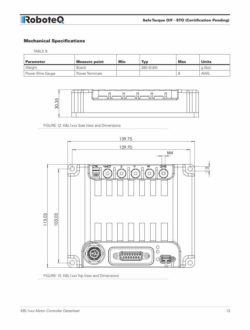
Mechanical Specifications
TABLE 9.
Parameter Measure point Min Typ Max Units
Weight Board 380 (0.84) g (lbs)
Power Wire Gauge Power Terminals 8 AWG
FIGURE 12. KBL1xxx Side View and Dimensions
M4
FIGURE 13. KBL1xxx Top View and Dimensions