Embed Size (px)
Citation preview

KE-436C
Please read this manual before using the machine.Please keep this manual within easy reach for quick reference.
ELECTRONIC LOCKSTITCH PATTERN TACKER WITH STEPPING FOOTAND PROGRAMMING FUNCTION
INSTRUCTION MANUAL
iKE-436C
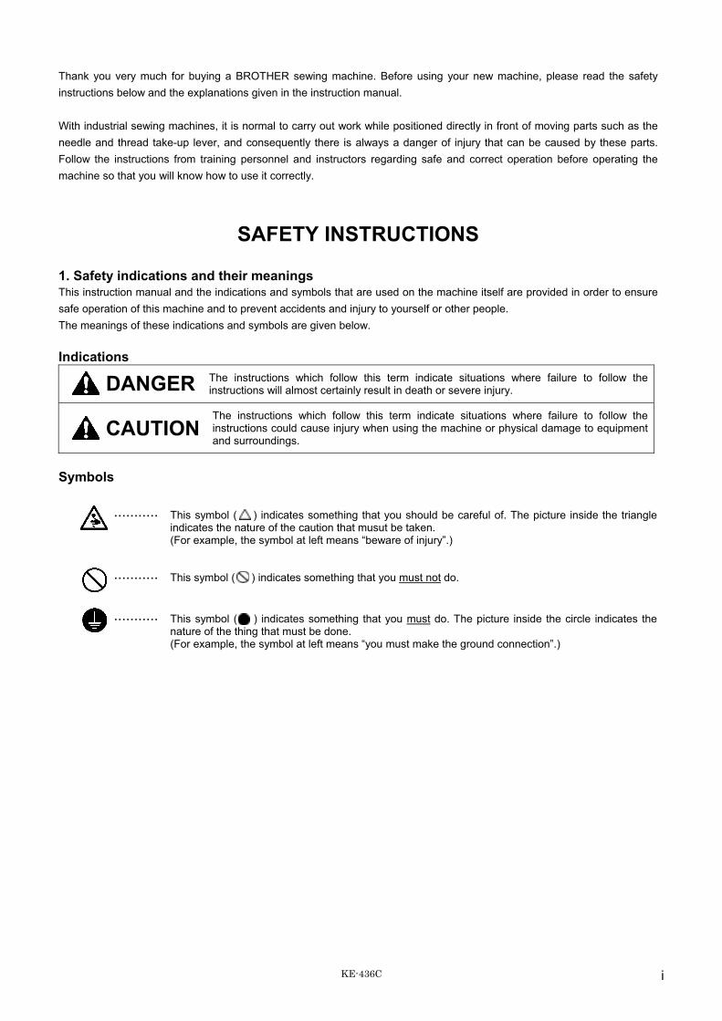
Thank you very much for buying a BROTHER sewing machine. Before using your new machine, please read the safety instructions below and the explanations given in the instruction manual.
With industrial sewing machines, it is normal to carry out work while positioned directly in front of moving parts such as the needle and thread take-up lever, and consequently there is always a danger of injury that can be caused by these parts. Follow the instructions from training personnel and instructors regarding safe and correct operation before operating the machine so that you will know how to use it correctly.
SAFETY INSTRUCTIONS
1. Safety indications and their meaningsThis instruction manual and the indications and symbols that are used on the machine itself are provided in order to ensure safe operation of this machine and to prevent accidents and injury to yourself or other people. The meanings of these indications and symbols are given below.
Indications
DANGER The instructions which follow this term indicate situations where failure to follow the instructions will almost certainly result in death or severe injury.
CAUTIONThe instructions which follow this term indicate situations where failure to follow the instructions could cause injury when using the machine or physical damage to equipment and surroundings.
Symbols
··········· This symbol ( ) indicates something that you should be careful of. The picture inside the triangle indicates the nature of the caution that musut be taken. (For example, the symbol at left means “beware of injury”.)
··········· This symbol ( ) indicates something that you must not do.
··········· This symbol ( ) indicates something that you must do. The picture inside the circle indicates the nature of the thing that must be done. (For example, the symbol at left means “you must make the ground connection”.)

ii KE-436C
2. Notes on safety
DANGERWait at least 5 minutes after turning off the power switch and disconnecting the power cord from the wall outlet beforeopening the face plate of the control box. Touching areas where high voltages are present can result in severe injury.
CAUTIONEnvironmental requirements
Use the sewing machine in an area which is free fromsources of strong electrical noise such as high-frequency welders.Sources of strong electrical noise may cause prob-lems with correct operation.Any fluctuations in the power supply voltage shouldbe within ±10% of the rated voltage for the machine.Voltage fluctuations which are greater than this maycause problems with correct operation.The power supply capacity should be greater than therequirements for the sewing machine’s electricalconsumption.Insufficient power supply capacity may cause prob-lems with correct operation.The pneumatic delivery capability should be greaterthan the requirements for the sewing machine’s totalair consumption.Insufficient pneumatic delivery capability may causeproblems with correct operation.
The ambient temperature should be within the rangeof 5°C to 35°C during use.Temperatures which are lower or higher than this maycause problems with correct operation.The relative humidity should be within the range of45% to 85% during use, and no dew formation shouldoccur in any devices.Excessively dry or humid environments and dew for-mation may cause problems with correct operation.Avoid exposure to direct sunlight during use.Exposure to direct sunlight may cause problems withcorrect operation.In the event of an electrical storm, turn off the powerand disconnect the power cord from the wall outlet.Lightning may cause problems with correct operation.
InstallationMachine installation should only be carried out by aqualified technician.Contact your Brother dealer or a qualified electricianfor any electrical work that may need to be done.The sewing machine weighs more than 56 kg. Theinstallation should be carried out by two or morepeople.Do not connect the power cord until installation iscomplete, otherwise the machine may operate if thefoot switch is depressed by mistake, which couldresult in injury.Hold the machine head with both hands when tilting itback or returning it to its original position.Furthermore, after tilting back the machine head, donot push the face plate side or the pulley side fromabove, as this could cause the machine head totopple over, which may result in personal injury ordamage to the machine.Be sure to connect the ground. If the ground connec-tion is not secure, you run a high risk of receiving aserious electric shock, and problems with correctoperation may also occur.
All cords should be secured at least 25 mm awayfrom any moving parts. Furthermore, do notexcessively bend the cords or secure them too firmlywith staples, otherwise there is the danger that fire orelectric shocks could occur.Install the belt covers to the machine head and motor.
If using a work table which has casters, the castersshould be secured in such a way so that they cannotmove.Be sure to wear protective goggles and gloves whenhandling the lubricating oil and grease, so that theydo not get into your eyes or onto your skin, otherwiseinflammation can result.Furthermore, do not drink the oil or eat the greaseunder any circumstances, as they can cause vomitingand diarrhoea.Keep the oil out of the reach of children.

iiiKE-436C
CAUTIONSewing
This sewing machine should only be used by opera-tors who have received the necessary training in safeuse beforehand.The sewing machine should not be used for anyapplications other than sewing.Be sure to wear protective goggles when using themachine.If goggles are not worn, there is the danger that if aneedle breaks, parts of the broken needle may enteryour eyes and injury may result.Set the needle to the needle up stop position beforeturning off the power.If this is not done, the wiper may strike the needle,which might cause the needle to break.Turn off the power switch at the following times,otherwise the machine may operate if the foot switchis depressed by mistake, which could result in injury.• When threading the needle• When replacing the needle and bobbin• When not using the machine and when leaving the
machine unattended
If using a work table which has casters, the castersshould be secured in such a way so that they cannotmove.Attach all safety devices before using the sewingmachine. If the machine is used without thesedevices attached, injury may result.Do not touch any of the moving parts or press anyobjects against the machine while sewing, as thismay result in personal injury or damage to themachine.If an error occurs in machine operation, or if abnormalnoises or smells are noticed, immediately turn off thepower switch. Then contact your nearest Brotherdealer or a qualified technician.If the machine develops a problem, contact yournearest Brother dealer or a qualified technician.
CleaningSet the needle to the needle up stop position beforeturning off the power.If this is not done, the wiper may strike the needle,which might cause the needle to break.Turn off the power switch before carrying outcleaning, otherwise the machine may operate if thefoot switch is depressed by mistake, which couldresult in injury.
Be sure to wear protective goggles and gloves whenhandling the lubricating oil and grease, so that theydo not get into your eyes or onto your skin, otherwiseinflammation can result.Furthermore, do not drink the oil or eat the greaseunder any circumstances, as they can cause vomitingand diarrhoea.Keep the oil out of the reach of children.
Maintenance and inspectionMaintenance and inspection of the sewing machineshould only be carried out by a qualified technician.Ask your Brother dealer or a qualified electrician tocarry out any maintenance and inspection of theelectrical system.Set the needle to the needle up stop position beforeturning off the power.If this is not done, the wiper may strike the needle,which might cause the needle to break.Turn off the power switch and disconnect the powercord from the wall outlet at the following times,otherwise the machine may operate if the foot switchis depressed by mistake, which could result in injury.• When carrying out inspection, adjustment and
maintenance• When replacing consumable parts such as the ro-
tary hookDisconnect the air hoses from the air supply and waitfor the needle on the pressure gauge to drop to “0”before carrying out inspection, adjustment and repairof any parts which use the pneumatic equipment.
If the power switch and air needs to be left on whencarrying out some adjustment, be extremely careful toobserve all safety precautions.
Hold the machine head with both hands when tilting itback or returning it to its original position.Furthermore, after tilting back the machine head, donot push the face plate side or the pulley side fromabove, as this could cause the machine head totopple over, which may result in personal injury ordamage to the machine.Use only the proper replacement parts as specifiedby Brother.If any safety devices have been removed, be abso-lutely sure to re-install them to their original positionsand check that they operate correctly before using themachine.Any problems in machine operation which result fromunauthorized modifications to the machine will not becovered by the warranty.
iv KE-436C
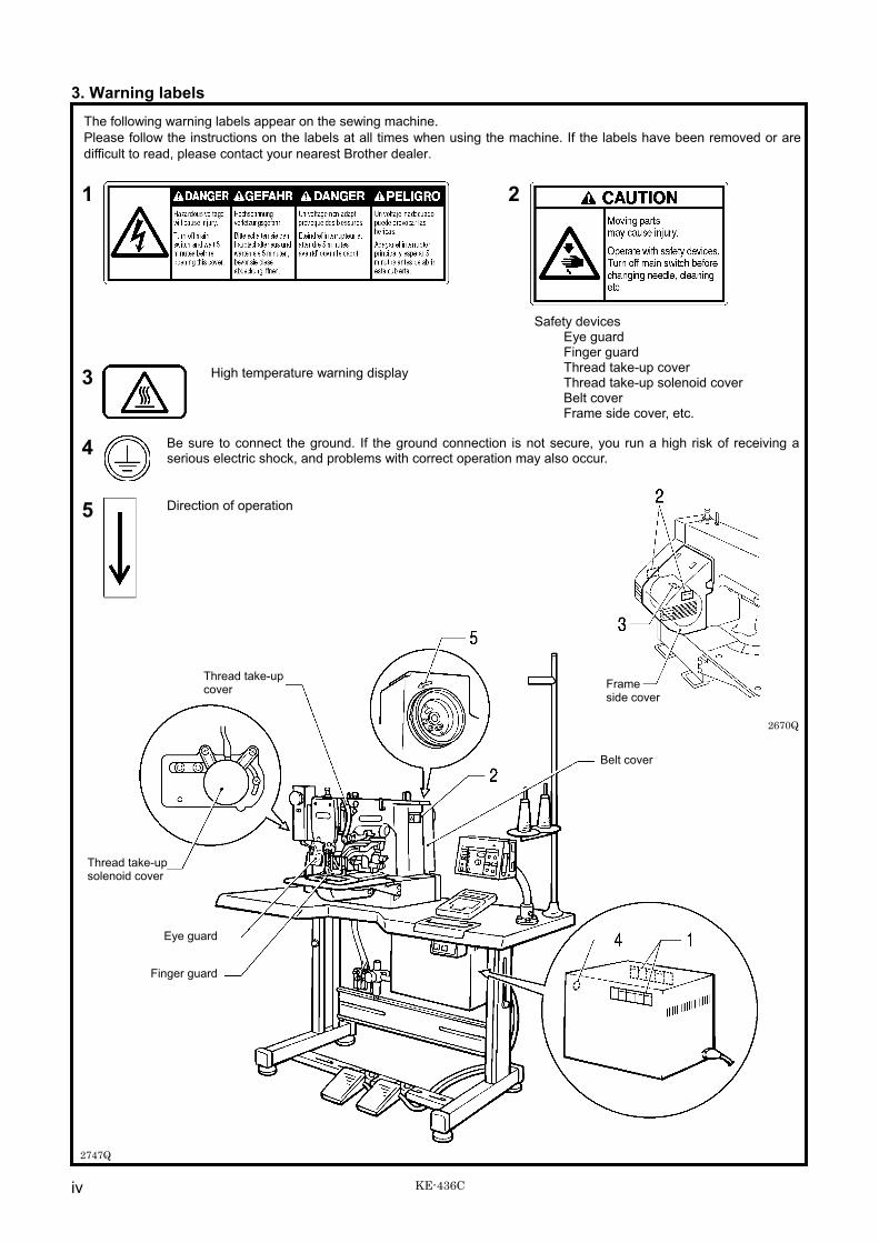
3. Warning labelsThe following warning labels appear on the sewing machine.Please follow the instructions on the labels at all times when using the machine. If the labels have been removed or aredifficult to read, please contact your nearest Brother dealer.
1 2
3 High temperature warning display
Safety devicesEye guardFinger guardThread take-up coverThread take-up solenoid coverBelt coverFrame side cover, etc.
4 Be sure to connect the ground. If the ground connection is not secure, you run a high risk of receiving aserious electric shock, and problems with correct operation may also occur.
5 Direction of operation
2747Q
2670Q
Thread take-upcover
Belt cover
Thread take-upsolenoid cover
Eye guard
Finger guard
Frameside cover
KE-436C
CONTENTS
1. NAME OF EACH PART............................... 1
2. SPECIFICATIONS ....................................... 2
2-1. Specifications ......................................................... 2
3.INSTALLATION............................................. 3
3-1. Power table............................................................. 33-2. Installing the control box......................................... 43-3. Installing the rubber cushions ................................. 53-4. Installing the oil pan................................................ 53-5. Installing the cushions ............................................ 53-6. Installing the switching plate ................................... 63-7. Installing the machine head .................................... 63-8. Installing the head rest ........................................... 73-9. Installing the liquid cooling tank, optional................ 73-10. Installing the operation panel................................ 73-11. Installing the programmer (option) .........................83-12. Connecting the ground wire.................................. 83-13. Connecting the cords.............................................93-14. Piping ..................................................................113-15. Installing the belt cover ........................................133-16. Installing the foot switch.......................................133-17. Installing the needle sub plate .............................143-18. Installing the spool stand .....................................153-19. Installing the eye guard........................................15
4. LUBRICATION............................................ 16
4-1. Lubrication points ..................................................16
5. USING THE OPERATION PANEL ............. 17
5-1. Explanation of panel..............................................175-2. Using the floppy disk .............................................195-3. Using the program R/W (Read/Write) switch .........215-4. Operating the foot switch.......................................225-5. Using the TEST switch
(Checking the sewing pattern)...............................225-6. Using the emergency stop switch ..........................235-7. Using the thread wiper switch................................235-8. Adjusting the sewing SPEED control .....................245-9. Changing the X-SCALE and Y-SCALE settings ....245-10. Using the bobbin thread counter..........................255-11. Using production counter.....................................265-12. Using single split mode........................................275-13. Shifting a stitch pattern ........................................28
6. CORRECT USE.......................................... 29
6-1. Selecting the needle and thread ............................296-2. Installing the needle...............................................296-3. Threading the upper thread ...................................296-4. Winding the lower thread.......................................306-5. Replacing the bobbin case and
threading the thread ..............................................31
6-6. Thread tension ...................................................... 31
7. SEWING ......................................................34
7-1. Before starting sewing........................................... 347-2. Sewing operation .................................................. 34
8. MAINTENANCE AND INSPECTION...........36
8-1. Checking the needle ............................................. 368-2. Cleaning the rotary hook ....................................... 368-3. Lubrication ............................................................ 378-4. Draining the oil ...................................................... 388-5. Cleaning the control box air inlet port.................... 388-6. Cleaning the air holes of belt
cover and frame side cover................................... 388-7. Cleaning the eye guard ......................................... 38
9. STANDARD ADJUSTMENTS .....................39
9-1. Adjusting the needle bar height............................. 399-2. Adjusting the needle bar lift amount ...................... 399-3. Adjusting the driver needle guard.......................... 409-4. Adjusting the needle clearance ............................. 409-5. Adjusting the shuttle race thread guide ................. 409-6. Adjusting the thread take-up amount .................... 419-7. Adjusting the movable knife .................................. 429-8. Adjusting the work clamp lift amount..................... 449-9. Work clamp adjustment......................................... 459-10. Changing the work clamp lift ............................... 459-11. Work clamp interchangeability ............................ 469-12. Adjusting the needle up stop position.................. 469-13. Adjusting the thread wiper................................... 479-14. Adjustment of air pressure .................................. 479-15. Checking the input sensor and DIP
switch input ......................................................... 489-16. Checking the input voltage.................................. 499-17. Clearing all memory settings............................... 49
10. DIP SWITCH..............................................50
10-1. Panel DIP switch functions.................................. 5010-2. DIP switches inside the control box..................... 51
11. CHANGING SPECIAL FUNCTIONSUSING THE MEMORY SWITCHES......... 52
12. SETTING THE WORK CLAMP MODE .....5612-1. Light work clamp ................................................. 57
13. TABLE OF ERROR CODES .....................58
14. GAUGE PARTS LIST ACCORDINGTO SUBCLASSES ....................................60
15. TROUBLESHOOTING ..............................63
16. OPTIONAL PARTS ...................................66

1. NAME OF EACH PART
1 KE-436C
1. NAME OF EACH PART
Safety devices;(1) Power switch (18) Finger guard(2) Control box (19) Eye guard(3) Operation panel (20) Thread take-up cover(4) Work clamp switch (21) Belt cover(5) Start switch (22) Frame side cover(6) Motor (23) Thread take-up solenoid cover(7) Programmer(8) Floppy drive(9) EMERGENCY STOP switch(10) Pulley(11) Spool stand(12) Thread take-up lever(13) Wiper solenoid cover(14) Thread wiper switch(15) Dip switch(16) Integrater(17) Solenoid valve
2672Q
2671Q

2. SPECIFICATIONS
2KE-436C
2. SPECIFICATIONS
2-1. Specifications
Stitch formation Single needle lock stitch
Maximum sewing speed 2,500 rpm (Pitch 3 mm)
Maximum pattern size 100 × 60 mm max.
Feed mechanism R-θ intermittent feed mechanism (pulse-motor driven mechanism)
Stitch length 0.1 - 10.0 mm
Number of stitches Variable
Maximum stitch number 20,000 stitches (One pattern)
Work clamp lifter Pneumatic type
Work clamp height 25 mm max.
Rotary hook Shuttle hook (shuttle hook 2, optional)
Wiper device Standard equipment
Thread trimmer device Standard equipment
Thread take-up device Standard equipment
Stepping foot lift amount 18 mm
Stepping foot stroke 0 mm, 3 - 8 mm
Safety device built-in stopping mechanism
Data storage method 3.5 floppy disk 2HD / 1.44MB, 2DD
Motor Three-phase 400W induction motor
Weights Machine head: 56 kg, Operation panel: 2.8 kg,Control box: 10 - 20 kg (depending on destination)
Power sourceSingle-phase 110, 220 - 230, 240V
3-phase 220 - 230, 380, 400VMaximum electric power consumption; 600VA
[Main use]Patterns up to a maximum size of 100 mm × 60 mm can be sewn.
For plain stitching of small articles, curtain darts, etc.Two-stage work clamp, light work clamp and inner clamping device (optional) can be used.
For attaching items, sewing labels, etc.

3. INSTALLATION
3 KE-436C
3. INSTALLATION
CAUTIONMachine installation should only be carried out by aqualified technician.Contact your Brother dealer or a qualified electricianfor any electrical work that may need to be done.The sewing machine head weighs more than 56 kg.The installation should be carried out by two or morepeople.Do not connect the power cord until installation iscomplete, otherwise the machine may operate if thefoot switch is depressed by mistake, which couldresult in injury.Hold the machine head with both hands when tilting itback or returning it to its original position.Furthermore, after tilting back the machine head, donot push the face plate side or the pulley side fromabove, as this could cause the machine head totopple over, which may result in personal injury ordamage to the machine.
All cords should be secured at least 25 mm awayfrom any moving parts. Furthermore, do notexcessively bend the cable or secure it too firmlystaples, otherwise there is the danger that fire orelectric shocks could occur.Be sure to connect the ground. If the groundconnection is not secure, you run the risk of receivinga serious electric shock, and problems with correctoperation may also occur.Install the belt covers to the machine head and motor.
3-1. Power table
Model code• Use the power table which has been specially designed for eachsewing machines.
* If using a commercially-available table, process it as shown inthe illustration below. Table/ legs assembly 127-P34-50001
Note:The thickness of the table should be at least 40 mm, and it should be strong enough to bear the weight and vibration of thesewing machine.If the distance A between the insides of the legs is less than 740 mm, move the control box installation position to the left(B = 247 mm).Check that the control box is at least 10 mm away from the leg. If the control box and leg are touching, it could cause thesewing machine to operate incorrectly.
1090Q

3. INSTALLATION
4KE-436C
3-2. Installing the control boxCheck that the IM sticker is attached to the side of the control box (in the position shown in the illustration).(KE series machine heads can only be used with control boxes which have the IM sticker attached.)
1. Remove the 12 screws (1), and then open the covers (panel mounting assembly (2) and main P.C. board mounting plate(3)).Note:
When opening the cover, hold it securely so that it does not fall down.2. Install the control box with the four accessory bolts (4), spacers (5), flat washers (6) and nuts (7) as shown in the illustration
above.* Use two nuts (7) at each installation location, and make sure that both nuts are tightened.
3. Close the covers (panel mounting assembly (2) and main P.C. board mounting plate (3)), and tighten them with the screws(1).* The main P.C. board mounting plate (3) will be opened again during “3-13. Connecting the cords”, so provisionally
tighten it with the screw (1).4. Install the power switch (8) with the two screws (9).5. Secure the power switch cord with the three staples (10).
2454Q
Spacers
Flat washers
Nuts

3. INSTALLATION
5 KE-436C
3-3. Installing the rubber cushionsInstall the rubber cushions (1) with the nails (2).* Install so that the head of the nail dose not protrude from
the rubber surface.
3-4. Installing the oil pan1. Insert the tabs of the oil pan (2) into the holes for the
cushions (1), and then secure it in place with the five nails(3) so that the oil pan (2) is not at an angle.
2. While pushing the oil pan (2) down from above, screw inthe oil container (4).
3-5. Installing the cushionsPlace the two cushions (1) into the holes in the work table sothat the notches are aligned with the tabs in the oil pan, andsecure them in place with the nails (2).* Install so that the head of the nail dose not protrude from
the rubber surface.
2489Q
2490Q
2491Q
2492Q
3. INSTALLATION
6KE-436C
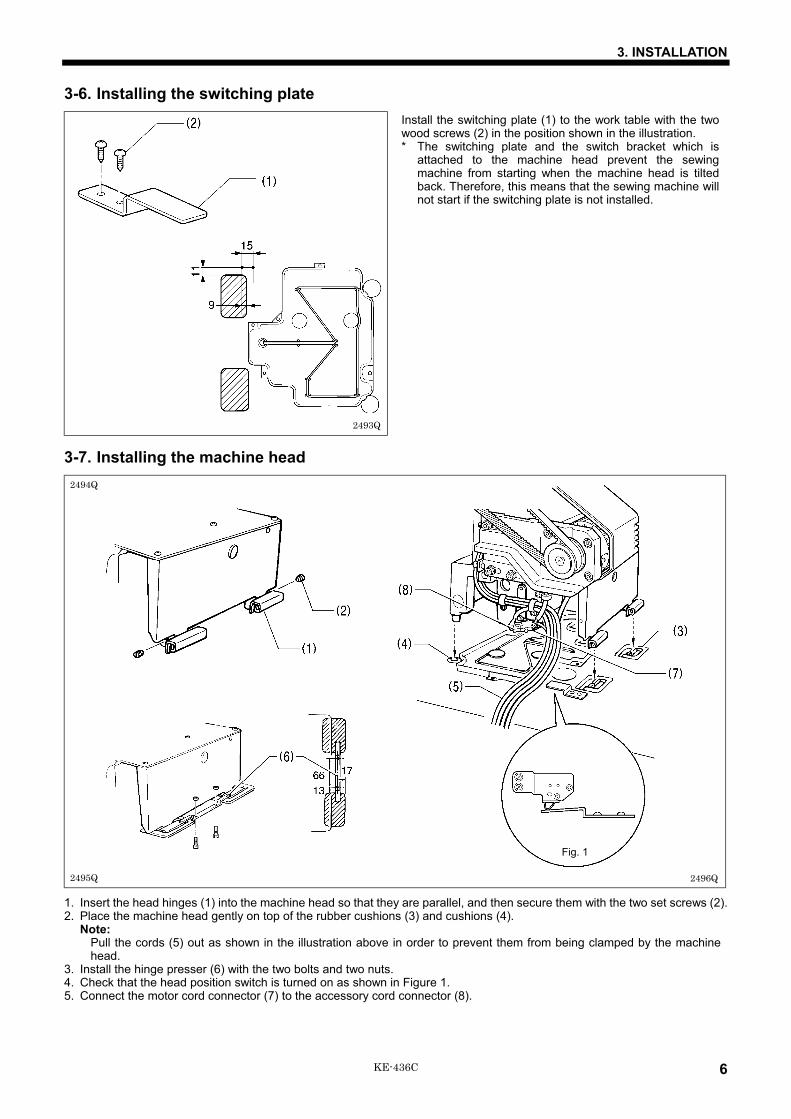
3-6. Installing the switching plateInstall the switching plate (1) to the work table with the twowood screws (2) in the position shown in the illustration.* The switching plate and the switch bracket which is
attached to the machine head prevent the sewingmachine from starting when the machine head is tiltedback. Therefore, this means that the sewing machine willnot start if the switching plate is not installed.
3-7. Installing the machine head
1. Insert the head hinges (1) into the machine head so that they are parallel, and then secure them with the two set screws (2).2. Place the machine head gently on top of the rubber cushions (3) and cushions (4).
Note:Pull the cords (5) out as shown in the illustration above in order to prevent them from being clamped by the machinehead.
3. Install the hinge presser (6) with the two bolts and two nuts.4. Check that the head position switch is turned on as shown in Figure 1.5. Connect the motor cord connector (7) to the accessory cord connector (8).
2493Q
2494Q
2495Q 2496Q
Fig. 1

3. INSTALLATION
7 KE-436C
3-8. Installing the head restTap the head rest (1) into the table hole.Note:
Tap the head rest securely into the table hole.
3-9. Installing the liquid cooling tank, optional1. Remove the rubber plug, and then push the liquid cooling
tank (1).2. Tighten it with the set screw (2).
3-10. Installing the operation panel1. Assemble the operation panel stand (1) and cushion A
(2). Then insert the bolts (4) together with the washers (3)into the three holes from above, and then tighten the nuts(5), washers (6) and cushion B (7) from below to securethe assembly.
Note:Tighten until the thickness of cushion B (7) becomesabout 1 mm.
2. Pass the cords of the control panel assembly through thehole in the operation panel stand (1).
3. Attach the rubber sheet (8) to the hole in the operationpanel stand (1) and then secure it with the bolt (9).
4. Insert the cord into the control box through the hole at theside of the box. Refer to “3-13. Connecting the cords” fordetails on connecting the cord.
5. Secure the cord with the staples (in five places).
2497Q
2498Q
2673Q

3. INSTALLATION
8KE-436C
3-11. Installing the programmer (option)1. Install the programmer support (2) to the work table with
the two screws (1).
2. Insert the programmer connector (4) securely into the leftside of the operation panel (3).
3-12. Connecting the ground wire
CAUTIONBe sure to connect the ground. If the ground connection is not secure, you run the risk of receiving a serious electricshock, and problems with correct operation may also occur.
2674Q
2675Q
2676Q
[Vertical]
[Flat]
2741Q
Connect to the power switch. However, theblack wire is insulated to the inside of thebox and is not used.
Connect to ground

3. INSTALLATION
9 KE-436C
3-13. Connecting the cords
2748Q
2502Q 2677Q 2678Q
3. INSTALLATION
10KE-436C
1. Gently tilt back the machine head.Note:
After tilting back the machine head, do not push the face side or the pulley side from above.2. Pass the cord bundle (1) from the machine head through the hole (2) in the work table.3. Gently return the machine head to its original position.4. Remove the six screws (3), and then open the control box cover (main P.C. board mounting plate (4)).
Note:When opening the cover, hold it securely so that it does not fall down.
5. Loosen the two screws (5), and then open the cord presser plate (6) in the direction of the white arrow and pass the cordbundle (1) through the opening.
6. Remove the screw (7), and then pass it through the terminal holes in the ground cord (8) from the machine head. Thenre-tighten the screw (7) so that the ground cord (8) is secured as shown in the illustration.
7. Remove the screw (9), and then pass it through the terminal hole in the ground cord (10) from the upper shaft motor andthe ground cord (11) from the operation panel. Then re-tighten the screw (9) so that the ground cords (10) and (11) aresecured as shown in the illustration.Note:
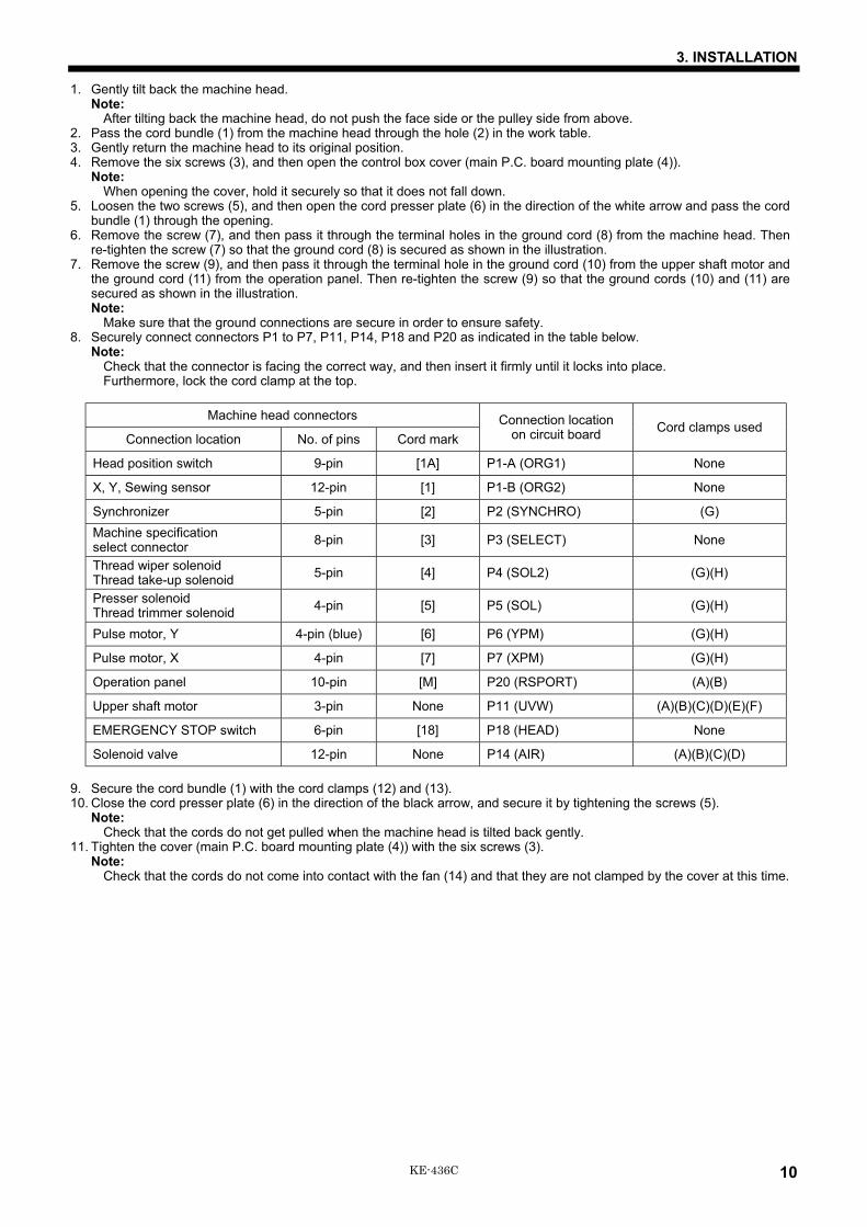
Make sure that the ground connections are secure in order to ensure safety.8. Securely connect connectors P1 to P7, P11, P14, P18 and P20 as indicated in the table below.
Note:Check that the connector is facing the correct way, and then insert it firmly until it locks into place.Furthermore, lock the cord clamp at the top.
Machine head connectors
Connection location No. of pins Cord markConnection location
on circuit board Cord clamps used
Head position switch 9-pin [1A] P1-A (ORG1) None
X, Y, Sewing sensor 12-pin [1] P1-B (ORG2) None
Synchronizer 5-pin [2] P2 (SYNCHRO) (G)Machine specificationselect connector 8-pin [3] P3 (SELECT) None
Thread wiper solenoidThread take-up solenoid 5-pin [4] P4 (SOL2) (G)(H)
Presser solenoidThread trimmer solenoid 4-pin [5] P5 (SOL) (G)(H)
Pulse motor, Y 4-pin (blue) [6] P6 (YPM) (G)(H)
Pulse motor, X 4-pin [7] P7 (XPM) (G)(H)
Operation panel 10-pin [M] P20 (RSPORT) (A)(B)
Upper shaft motor 3-pin None P11 (UVW) (A)(B)(C)(D)(E)(F)
EMERGENCY STOP switch 6-pin [18] P18 (HEAD) None
Solenoid valve 12-pin None P14 (AIR) (A)(B)(C)(D)
9. Secure the cord bundle (1) with the cord clamps (12) and (13).10. Close the cord presser plate (6) in the direction of the black arrow, and secure it by tightening the screws (5).
Note:Check that the cords do not get pulled when the machine head is tilted back gently.
11. Tighten the cover (main P.C. board mounting plate (4)) with the six screws (3).Note:
Check that the cords do not come into contact with the fan (14) and that they are not clamped by the cover at this time.

3. INSTALLATION
11 KE-436C
3-14. Piping
Connect air tubes in accordance with the identified numbers in the figure, and then bind them with some fastening bands. Besure not to crush the air tubes at that time.* Light work clamp mode can be used by changing over the air tube connections.
(Refer to “12. Setting the work clamp mode”.)
0433Q
Cylinder L
Stepping cylinder
Cylinder R
Upper knob
Lower knobSwitch
1092Q

3. INSTALLATION
12KE-436C
3-14-1. Installing the air unitMake sure that the air unit does not touch the control box or the work table leg.
<When installing to the underside of the work table>1. Remove the two screws (1) and the valve setting plate (2).2. Turn the valve setting plate (2) upside down, and install it to the underside of the work table using the two wood screws (3)
and washers (4) which are provided as accessories.* At this time, install the valve setting plate (2) in a position where it will not be in the way when using the machine. (The
recommended installation position is shown in Figure 1.)3. Install the ground cord (5) to the machine head.4. Install the air unit (6) to the valve setting plate (2) with two screws (1).5. Connect the air hose (7).6. Adjust the air pressure. (Refer to “9-14. Adjusting the air pressure”.)
<When installing to a beam>1. Make holes in the beam as shown in the illustration above. (Button hole diameter is 5.4 mm. The pitch is 50mm.)2. Install the air unit (8) to the beam with two accessory screws (9) and two bolts (10).3. Install the ground cord (11) to the machine head.4. Connect the air hose (12).5. Adjust the air pressure. (Refer to “9-14. Adjusting the air pressure”.)
3-14-2. Adjusting the speed controllerThe speeds at which the work clamps are raised and lowered can be adjusted by loosening or tightening the valve controlknobs. The speeds should be adjusted to speeds which are suitable for the intended application.• If the upper control knob is tightened, the raising speed becomes slower; if it is loosened, the raising speed becomes faster.• If the lower control knob is tightened, the lowering speed becomes slower; if it is loosened, the lowering speed becomes
faster.• When the power is turned off, the work clamps can be operated by pressing the switch.Note:
Adjust the control knobs so that the left and right work clamps both operate at the same speed. (Valve 1 and 2)Adjust the control knobs so that the stepping work clamp operates more quickly. (Valve 3)
2598Q
2680Q 1093Q
2681Q
Fig. 1
3. INSTALLATION
13 KE-436C
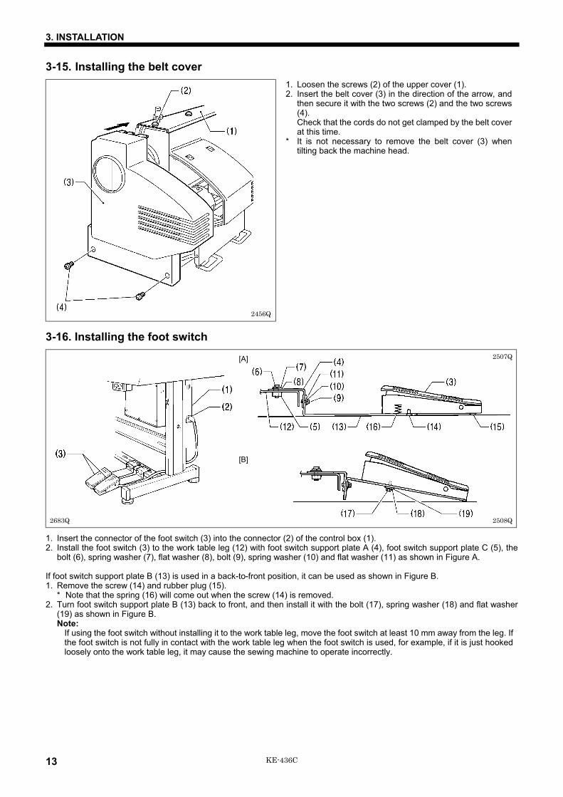
3-15. Installing the belt cover1. Loosen the screws (2) of the upper cover (1).2. Insert the belt cover (3) in the direction of the arrow, and
then secure it with the two screws (2) and the two screws(4).Check that the cords do not get clamped by the belt coverat this time.
* It is not necessary to remove the belt cover (3) whentilting back the machine head.
3-16. Installing the foot switch
1. Insert the connector of the foot switch (3) into the connector (2) of the control box (1).2. Install the foot switch (3) to the work table leg (12) with foot switch support plate A (4), foot switch support plate C (5), the
bolt (6), spring washer (7), flat washer (8), bolt (9), spring washer (10) and flat washer (11) as shown in Figure A.
If foot switch support plate B (13) is used in a back-to-front position, it can be used as shown in Figure B.1. Remove the screw (14) and rubber plug (15).
* Note that the spring (16) will come out when the screw (14) is removed.2. Turn foot switch support plate B (13) back to front, and then install it with the bolt (17), spring washer (18) and flat washer
(19) as shown in Figure B.Note:
If using the foot switch without installing it to the work table leg, move the foot switch at least 10 mm away from the leg. Ifthe foot switch is not fully in contact with the work table leg when the foot switch is used, for example, if it is just hookedloosely onto the work table leg, it may cause the sewing machine to operate incorrectly.
2456Q
2683Q
2507Q
2508Q
[B]
[A]

3. INSTALLATION
14KE-436C
3-17. Installing the needle sub plate1. Install the four needle sub plate supports (1) with the four
screws (2).
2. Insert the needle sub plate (3) from the front of themachine so that it is level.Note:
Insert the needle sub plate (3) so that the X feed levercap (4) sits on top of the needle sub plate (3).
3. Install the needle sub plate (3) with the four screws (5).4. Loosen the screws (2) and make fine adjustments to the
height of the needle sub plate (3) so that it is at the sameheight as the needle plate (6).
5. Provisionally secure the two auxiliary plate supports (7)with the washers (8) and the screws (9) and (10), andthen firmly tighten the screws (9) and (10) in that order.
2601Q
2599Q
2600Q

3. INSTALLATION
15 KE-436C
3-18. Installing the spool standAssemble the spool stand (1) while referring to the spoolstand instruction manual, and then install the spool stand (1)at the right side of the work table.
3-19. Installing the eye guard
CAUTIONAttach all safety devices before using the sewing machine.If the machine is used without these devices attached, injury may result.
Install the eye guard assy (1) to the face plate with the twoscrews (2).
2509Q
2684Q
4. LUBRICATION
16KE-436C
4. LUBRICATION
CAUTIONTurn off the power switch before starting lubricating, otherwise the machine may operate if the foot switch isdepressed by mistake, which could result in injury.Be sure to wear protective goggles and gloves when handling the lubricating oil and grease, so that they do not getinto your eyes or onto your skin, otherwise inflammation can result.Furthermore, do not drink the oil or eat the grease under any circumstances, as they can cause vomiting anddiarrhoea.Keep the oil out of the reach of children.
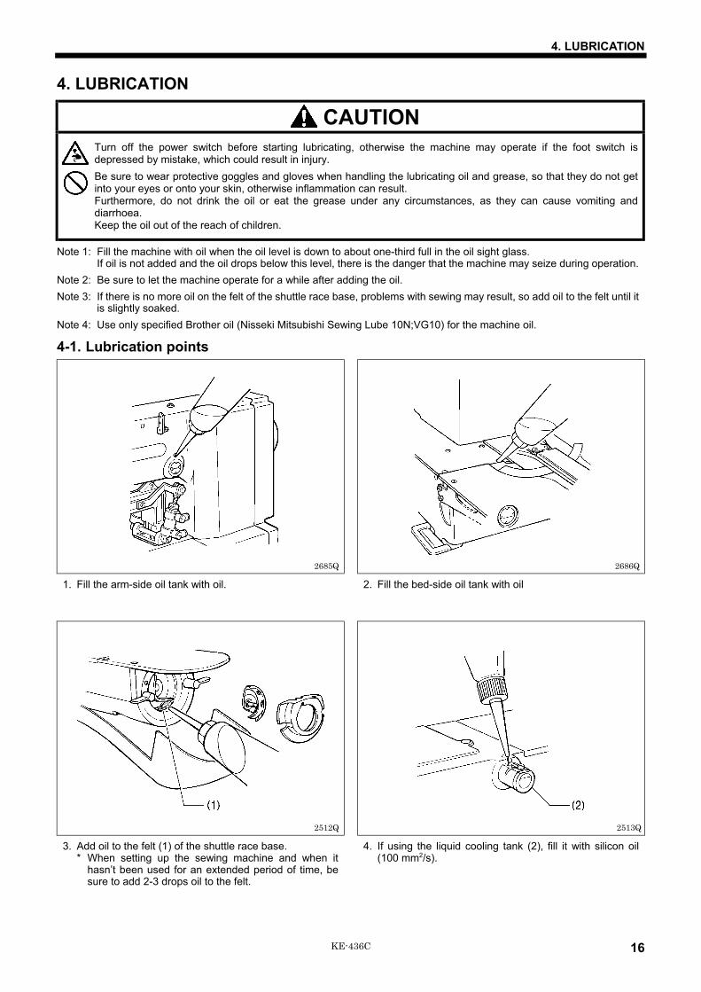
Note 1: Fill the machine with oil when the oil level is down to about one-third full in the oil sight glass.If oil is not added and the oil drops below this level, there is the danger that the machine may seize during operation.
Note 2: Be sure to let the machine operate for a while after adding the oil.Note 3: If there is no more oil on the felt of the shuttle race base, problems with sewing may result, so add oil to the felt until it
is slightly soaked.Note 4: Use only specified Brother oil (Nisseki Mitsubishi Sewing Lube 10N;VG10) for the machine oil.
4-1. Lubrication points
1. Fill the arm-side oil tank with oil. 2. Fill the bed-side oil tank with oil
3. Add oil to the felt (1) of the shuttle race base.* When setting up the sewing machine and when it
hasn’t been used for an extended period of time, besure to add 2-3 drops oil to the felt.
4. If using the liquid cooling tank (2), fill it with silicon oil(100 mm2/s).
2685Q 2686Q
2512Q 2513Q
5. USING THE OPERATION PANEL
17 KE-436C
5. USING THE OPERATION PANEL5-1. Explanation of panel
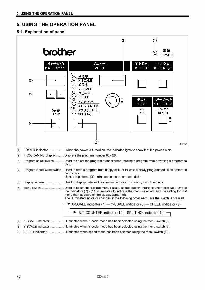
(1) POWER indicator................... When the power is turned on, the indicator lights to show that the power is on.
(2) PROGRAM No. display..........Displays the program number 00 - 99.
(3) Program select switch............Used to select the program number when reading a program from or writing a program todisk.
(4) Program Read/Write switch ...Used to read a program from floppy disk, or to write a newly programmed stitch pattern tofloppy disk.Up to ten patterns (00 - 99) can be stored on each disk.
(5) Display screen .......................Used to display data such as menus, errors and memory switch settings.
(6) Menu switch...........................Used to select the desired menu ( scale, speed, bobbin thread counter, split No.). One ofthe indicators (7) - (11) illuminates to indicate the menu selected, and the setting for thatmenu then appears on the display screen (5).The illuminated indicator changes in the following order each time the switch is pressed.
X-SCALE indicator (7) −− Y-SCALE indicator (8) −− SPEED indicator (9)
B.T. COUNTER indicator (10) SPLIT NO. indicator (11)
(7) X-SCALE indicator................. Illuminates when X-scale mode has been selected using the menu switch (6).
(8) Y-SCALE indicator................. Illuminates when Y-scale mode has been selected using the menu switch (6).
(9) SPEED indicator .................... Illuminates when speed mode has been selected using the menu switch (6).
2687Q

5. USING THE OPERATION PANEL
18KE-436C
(10) Bobbin Thread COUNTER..... Illuminates when bobbin thread counter mode has been selected using the menu switchindicator (6).
(11) SPLIT NO. indicator............... Illuminates when split No. mode has been selected using the menu switch (6).
(12) Dial ........................................The setting shown on the display screen (5) can be changed by turning this dial whilepressing the STEP BACK switch (17).
(13) Bobbin Thread SET switch. ...Used to store the number of work pieces displayed in the bobbin thread counter to floppydisk.
(14) Bobbin Thread CHANGE.......Used to continue sewing after replacing the bobbin thread.switch (An alarm will sound when the counter reads <000>. Sewing is not possible when the
counter reads <000>.) (Refer to “5-9. Using the bobbin thread counter”.)
(15) TEST switch...........................Used to move the feed mechanism only in order to confirm a programmed stitch pattern.
(16) TEST indicator .......................Lights when the TEST switch is pressed.
(17) STEP BACK switch................Used when winding a fresh bobbin, or when correcting a stitch pattern due to a broken(RESET switch) needle thread.
Also used to reset error displays.
2688Q
5. USING THE OPERATION PANEL
19 KE-436C
5-2. Using the floppy diskCompatible types of floppy disk
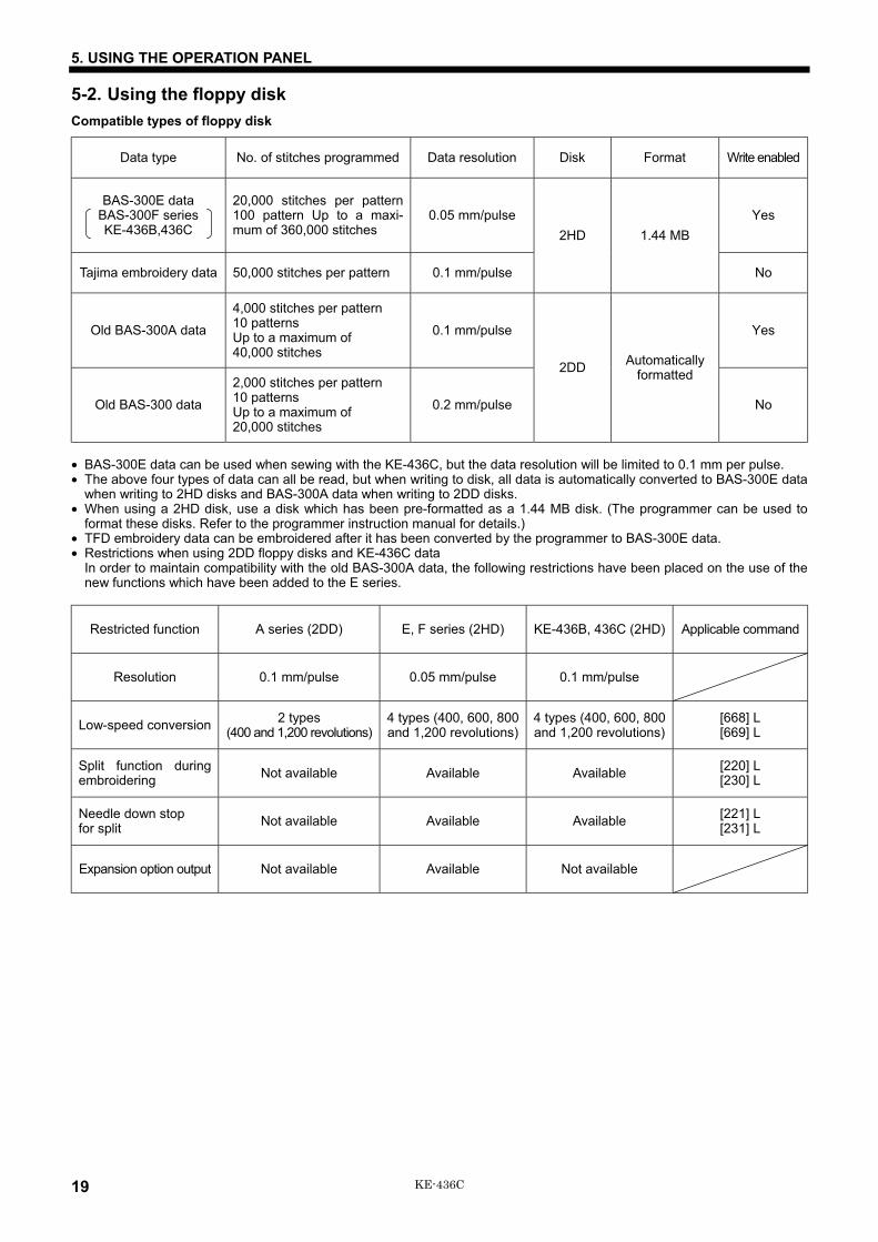
Data type No. of stitches programmed Data resolution Disk Format Write enabled
BAS-300E dataBAS-300F seriesKE-436B,436C
20,000 stitches per pattern100 pattern Up to a maxi-mum of 360,000 stitches
0.05 mm/pulse Yes
Tajima embroidery data 50,000 stitches per pattern 0.1 mm/pulse
2HD 1.44 MB
No
Old BAS-300A data
4,000 stitches per pattern10 patternsUp to a maximum of40,000 stitches
0.1 mm/pulse Yes
Old BAS-300 data
2,000 stitches per pattern10 patternsUp to a maximum of20,000 stitches
0.2 mm/pulse
2DD Automaticallyformatted
No
• BAS-300E data can be used when sewing with the KE-436C, but the data resolution will be limited to 0.1 mm per pulse.• The above four types of data can all be read, but when writing to disk, all data is automatically converted to BAS-300E data
when writing to 2HD disks and BAS-300A data when writing to 2DD disks.• When using a 2HD disk, use a disk which has been pre-formatted as a 1.44 MB disk. (The programmer can be used to
format these disks. Refer to the programmer instruction manual for details.)• TFD embroidery data can be embroidered after it has been converted by the programmer to BAS-300E data.• Restrictions when using 2DD floppy disks and KE-436C data
In order to maintain compatibility with the old BAS-300A data, the following restrictions have been placed on the use of thenew functions which have been added to the E series.
Restricted function A series (2DD) E, F series (2HD) KE-436B, 436C (2HD) Applicable command
Resolution 0.1 mm/pulse 0.05 mm/pulse 0.1 mm/pulse
Low-speed conversion 2 types(400 and 1,200 revolutions)
4 types (400, 600, 800and 1,200 revolutions)
4 types (400, 600, 800and 1,200 revolutions)
[668] L[669] L
Split function duringembroidering Not available Available Available [220] L
[230] L
Needle down stopfor split Not available Available Available [221] L
[231] L
Expansion option output Not available Available Not available

5. USING THE OPERATION PANEL
20KE-436C
Setting the floppy disk
1. Turn on the power switch (1). The POWER indicator (2) will illuminate and the machine model number will appear on thedisplay screen.
2. Hold the disk (3) with the label up and the metal shutter to the front, and insert the disk into the drive (4). It will click intoplace.
3. To eject the disk, press the eject button (5).
Note:• Slide the write protector (6) on the back of the disk up (the window opens) to lock the disk and prevent accidental
erasure of the disk contents.• Inserting the disk into the drive upside down or backwards may damage the drive and will prevent reading or writing of
data.• Be sure to store your disks away from any magnets or magnetic sources, including radios, televisions, telephones, and
other devices. Magnetism can erase or damage disk contents. Also, be careful to prevent exposure of the disk to oil ordust.
• Be sure to make a copy of the floppy disk containing sewing data and keep the master floppy disk.• When the R /W operation is not in operation, eject the floppy disk from the floppy disk drive and keep it in a case for
floppy disk only to prevent exposure of the disk to dust.• When the “E.4F” error (Reading error of sewing data) occurs very often;
1. Clean the floppy disk drive using the cleaning disk.2. Read the sewing data. If the “E.4F” error occurs again, the floppy disk may be damaged. In this case, clean the floppy
disk drive with the cleaning disk again.3. Read the sewing data from the master floppy disk and write it in a new floppy disk. Do not use any damaged floppy
disks again.
How to use the cleaning disk1. Insert the cleaning disk into the floppy disk drive.2. Select a program number (0-9), and press the “R / W” switch. If you select the same program number for cleaning every
time, the same location of the cleaning disk is used and the lifetime of the cleaning disk will become short. Next time youclean it, select a different number.
3. After the cleaning is completed, the “E.4F” error appears. The error appears because the cleaning disk has no data. This isnormal.
4. Cancel the error and eject the cleaning disk.
2689Q 2691Q2690Q
Unlocked writingpossible
Window open
Locked writingpossible
5. USING THE OPERATION PANEL
21 KE-436C
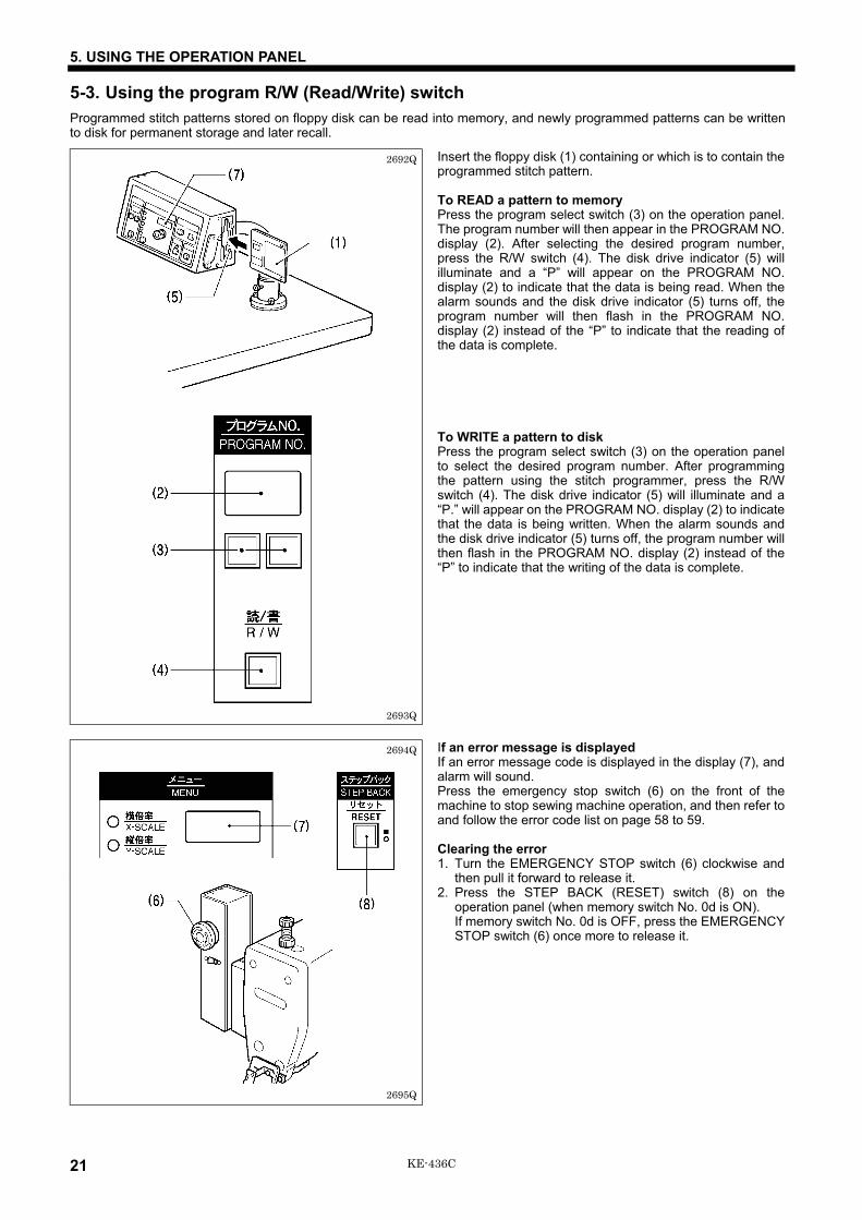
5-3. Using the program R/W (Read/Write) switchProgrammed stitch patterns stored on floppy disk can be read into memory, and newly programmed patterns can be writtento disk for permanent storage and later recall.
Insert the floppy disk (1) containing or which is to contain theprogrammed stitch pattern.
To READ a pattern to memoryPress the program select switch (3) on the operation panel.The program number will then appear in the PROGRAM NO.display (2). After selecting the desired program number,press the R/W switch (4). The disk drive indicator (5) willilluminate and a “P” will appear on the PROGRAM NO.display (2) to indicate that the data is being read. When thealarm sounds and the disk drive indicator (5) turns off, theprogram number will then flash in the PROGRAM NO.display (2) instead of the “P” to indicate that the reading ofthe data is complete.
To WRITE a pattern to diskPress the program select switch (3) on the operation panelto select the desired program number. After programmingthe pattern using the stitch programmer, press the R/Wswitch (4). The disk drive indicator (5) will illuminate and a“P.” will appear on the PROGRAM NO. display (2) to indicatethat the data is being written. When the alarm sounds andthe disk drive indicator (5) turns off, the program number willthen flash in the PROGRAM NO. display (2) instead of the“P” to indicate that the writing of the data is complete.
If an error message is displayedIf an error message code is displayed in the display (7), andalarm will sound.Press the emergency stop switch (6) on the front of themachine to stop sewing machine operation, and then refer toand follow the error code list on page 58 to 59.
Clearing the error1. Turn the EMERGENCY STOP switch (6) clockwise and
then pull it forward to release it.2. Press the STEP BACK (RESET) switch (8) on the
operation panel (when memory switch No. 0d is ON).If memory switch No. 0d is OFF, press the EMERGENCYSTOP switch (6) once more to release it.
2692Q
2693Q
2694Q
2695Q
5. USING THE OPERATION PANEL
22KE-436C
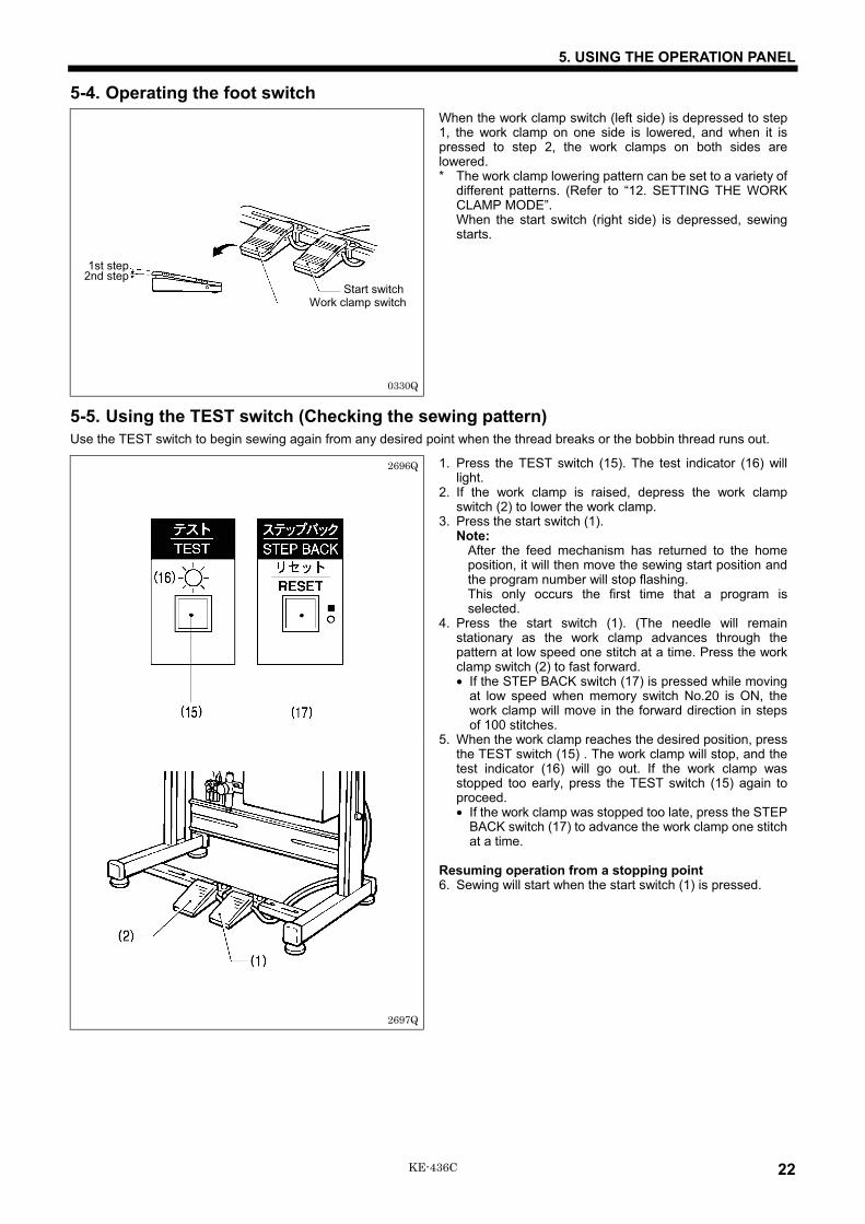
5-4. Operating the foot switchWhen the work clamp switch (left side) is depressed to step1, the work clamp on one side is lowered, and when it ispressed to step 2, the work clamps on both sides arelowered.* The work clamp lowering pattern can be set to a variety of
different patterns. (Refer to “12. SETTING THE WORKCLAMP MODE”.When the start switch (right side) is depressed, sewingstarts.
5-5. Using the TEST switch (Checking the sewing pattern)Use the TEST switch to begin sewing again from any desired point when the thread breaks or the bobbin thread runs out.
1. Press the TEST switch (15). The test indicator (16) willlight.
2. If the work clamp is raised, depress the work clampswitch (2) to lower the work clamp.
3. Press the start switch (1).Note:
After the feed mechanism has returned to the homeposition, it will then move the sewing start position andthe program number will stop flashing.This only occurs the first time that a program isselected.
4. Press the start switch (1). (The needle will remainstationary as the work clamp advances through thepattern at low speed one stitch at a time. Press the workclamp switch (2) to fast forward.• If the STEP BACK switch (17) is pressed while moving
at low speed when memory switch No.20 is ON, thework clamp will move in the forward direction in stepsof 100 stitches.
5. When the work clamp reaches the desired position, pressthe TEST switch (15) . The work clamp will stop, and thetest indicator (16) will go out. If the work clamp wasstopped too early, press the TEST switch (15) again toproceed.• If the work clamp was stopped too late, press the STEP
BACK switch (17) to advance the work clamp one stitchat a time.
Resuming operation from a stopping point6. Sewing will start when the start switch (1) is pressed.
0330Q
Start switch Work clamp switch
1st step2nd step
2697Q
2696Q
5. USING THE OPERATION PANEL
23 KE-436C
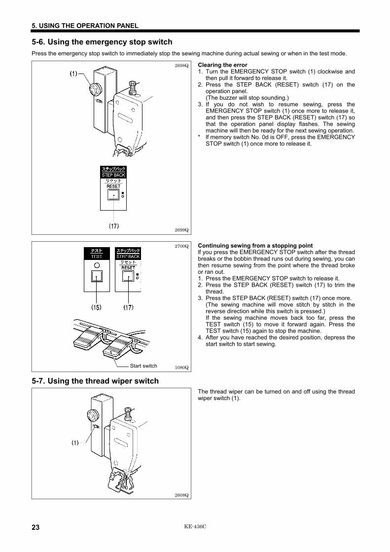
5-6. Using the emergency stop switchPress the emergency stop switch to immediately stop the sewing machine during actual sewing or when in the test mode.
Clearing the error1. Turn the EMERGENCY STOP switch (1) clockwise and
then pull it forward to release it.2. Press the STEP BACK (RESET) switch (17) on the
operation panel.(The buzzer will stop sounding.)
3. If you do not wish to resume sewing, press theEMERGENCY STOP switch (1) once more to release it,and then press the STEP BACK (RESET) switch (17) sothat the operation panel display flashes. The sewingmachine will then be ready for the next sewing operation.
* lf memory switch No. 0d is OFF, press the EMERGENCYSTOP switch (1) once more to release it.
Continuing sewing from a stopping pointlf you press the EMERGENCY STOP switch after the threadbreaks or the bobbin thread runs out during sewing, you canthen resume sewing from the point where the thread brokeor ran out.1. Press the EMERGENCY STOP switch to release it.2. Press the STEP BACK (RESET) switch (17) to trim the
thread.3. Press the STEP BACK (RESET) switch (17) once more.
(The sewing machine will move stitch by stitch in thereverse direction while this switch is pressed.)If the sewing machine moves back too far, press theTEST switch (15) to move it forward again. Press theTEST switch (15) again to stop the machine.
4. After you have reached the desired position, depress thestart switch to start sewing.
5-7. Using the thread wiper switchThe thread wiper can be turned on and off using the threadwiper switch (1).
2698Q
2699Q
2700Q
1080QStart switch
2608Q

5. USING THE OPERATION PANEL
24KE-436C
5-8. Adjusting the sewing SPEED controlThe sewing speed can be changed in steps of 100 rpm to the appropriate speeds for each stitch length setting.
1. Press the MENU switch (6) until the SPEED indicator (9)illuminates.
2. While pressing the STEP BACK switch (17), turn the dial(12) until the desired speed is displayed.• The display will change in steps of 10 rpm.
5-9. Changing the X-SCALE and Y-SCALE settings1. Press the MENU switch (6) until the X-SCALE indicator
(7) or the Y-SCALE indicator (8) illuminates.2. While pressing the STEP BACK switch (17), turn the dial
(12) until the desired ratio flashes on the display.• The scale setting is displayed as a percentage.
3. The program number will flash, and after the homeposition is detected the flashing will stop.
2701Q
2702Q

5. USING THE OPERATION PANEL
25 KE-436C
5-10. Using the bobbin thread counterSet the bobbin thread counter to display the number of pieces of the selected pattern which can be sewn with the amount ofthread on the bobbin to avoid running out of bobbin thread in the middle of a pattern.
1. Press the MENU switch (6) until the B.T. COUNTER indicator (10) illuminates.• The bobbin thread counter can be set to any number from <001> to <999>. If the counter is set to <000>, sewing
continues irrespective of the amount of bobbin thread remaining.2. While pressing the STEP BACK switch (17), turn the dial (12) to set the number of articles to be embroidered.3. Insert the floppy disk and press the bobbin thread SET switch (13). An alarm will beep twice. This will record the number of
work pieces shown in the counter (5) to the disk.4. The number shown in the counter (5) will decrease one each time the stitch pattern is completed. When the number of
patterns shown in the counter is sewn, the counter (5) will red <000>, and an alarm will sound.(The sewing machine will not start even if the start switch is pressed.)
5. Press the bobbin thread change switch (14) and replace the bobbin. The alarm will stop, and the number of work pieces setin step 3 will be displayed again in the counter (5).
2703Q

5. USING THE OPERATION PANEL
26KE-436C
5-11. Using production counterBoth PRO. NO. and B.T. COUNTER displays are available for the five-digit PRODUCTION counter.
1. While pressing the TEST switch (15), press the B.T.SET switch (13). The B.T. COUNTER indicator (10) and the SPLIT NO.indicator (11) will both illuminate, and the production counter value will appear on the program number display (2) and onthe display screen (5).• Press the B.T. CHANGE switch (14). The PRODUCTION counter will display <00000>.• The production counter can be set to a value between <00000> and <99999> by turning the dial (12) while pressing the
STEP BACK switch (17).2. Depress the start switch to start embroidering.3. Press the TEST switch (15) or the MENU switch (6). The TEST indicator (16) will switch off and the contents of each display
screen will return to the normal display.
2704Q
5. USING THE OPERATION PANEL
27 KE-436C
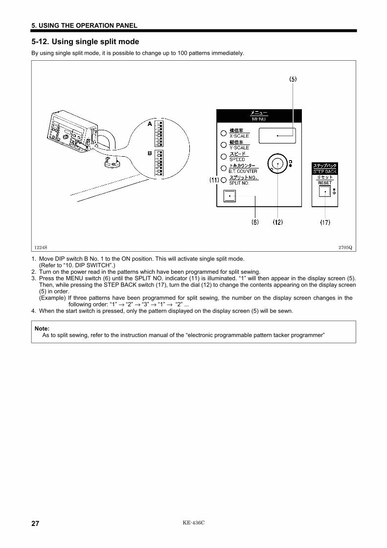
5-12. Using single split modeBy using single split mode, it is possible to change up to 100 patterns immediately.
1. Move DIP switch B No. 1 to the ON position. This will activate single split mode.(Refer to “10. DIP SWITCH”.)
2. Turn on the power read in the patterns which have been programmed for split sewing.3. Press the MENU switch (6) until the SPLIT NO. indicator (11) is illuminated. “1” will then appear in the display screen (5).
Then, while pressing the STEP BACK switch (17), turn the dial (12) to change the contents appearing on the display screen(5) in order.(Example) If three patterns have been programmed for split sewing, the number on the display screen changes in the
following order: “1” → “2” → “3” → “1” → “2” ...4. When the start switch is pressed, only the pattern displayed on the display screen (5) will be sewn.
Note:As to split sewing, refer to the instruction manual of the “electronic programmable pattern tacker programmer”
2705Q1224S

5. USING THE OPERATION PANEL
28KE-436C
5-13. Shifting a stitch pattern• Programs which have already been programmed can be moved up, down and to the left and right.
(However, such patterns will be reset if the power supply is turned off or the program number is changed.)• The feed position can be set to the any position desired.
1. After the program data has been read, depress the start switch to move the feed mechanism to the sewing start position. Ifyou carry out the following procedure while the program number display (2) is flashing (if the start switch has not beendepressed) → The feed position can be set to any position, but it will not be possible to move the stitch pattern.
2. Press the MENU switch (6) until the B.T. COUNTER indicator (10) illuminates.3. Press and hold the TEST switch (15) and press the R/W switch (4). The test indicator (16) will light, and < > will appear
in the counter (5).4. Press the MENU switch (6) so that either the X-SCALE indicator (7) or Y-SCALE indicator (8) illuminates.5. Turn the setting dial (12) to move the feed mechanism one pulse at a time.
• If the setting dial is turned counterclockwise while the X-SCALE indicator is illuminated, the feed mechanism will moveto the right.
• If the setting dial is turned clockwise while the X-SCALE indicator is illuminated, the feed mechanism will move to theleft.
• If the setting dial is turned counterclockwise while the Y-SCALE indicator is illuminated, the feed mechanism will moveup.
• If the setting dial is turned clockwise while the Y-SCALE indicator is illuminated, the feed mechanism will move down.6. When the TEST switch (15) is pressed after the above fine adjustments have been made, the TEST indicator (16) and
display window (5) will both switch off and movement of the stitch pattern will be completed.Note:
When moving the stitch pattern, the sewing start position can be moved to any desired point within the sewing area, butif the pattern goes outside the sewing area, an error will occur during sewing and you will not be able to sew the pattern.Give consideration to the pattern as a whole when moving it.
1227S2706Q
6. CORRECT USE
29 KE-436C
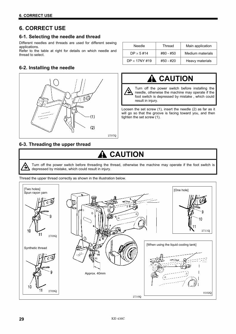
6. CORRECT USE6-1. Selecting the needle and threadDifferent needles and threads are used for different sewingapplications.Refer to the table at right for details on which needle andthread to select.
6-2. Installing the needle
CAUTIONTurn off the power switch before installing theneedle, otherwise the machine may operate if thefoot switch is depressed by mistake , which couldresult in injury.
Loosen the set screw (1), insert the needle (2) as far as itwill go so that the groove is facing toward you, and thentighten the set screw (1).
6-3. Threading the upper thread
CAUTIONTurn off the power switch before threading the thread, otherwise the machine may operate if the foot switch isdepressed by mistake, which could result in injury.
Thread the upper thread correctly as shown in the illustration below.
Needle Thread Main application
DP × 5 #14 #80 - #50 Medium materials
DP × 17NY #19 #50 - #20 Heavy materials
2707Q
Synthetic thread
[One hole]
2710Q0102Q
[Two holes]Spun rayon yarn
2708Q
Approx. 40mm
[When using the liquid cooling tank]
2709Q
2711Q

6. CORRECT USE
30KE-436C
6-4. Winding the lower thread
CAUTIONDo not touch any of the moving parts or press any objects against the machine while winding the lower thread, as thismay result in personal injury or damage to the machine.
1. Place the bobbin all the way onto the shaft.
2. Thread the thread as shown in the illustration atright, wind the thread around the bobbin severaltimes in the direction of the arrow, and thenpress the bobbin presser (1).
3. Turn on the power switch.(The POWER indicator on the operation panel willilluminate.)
4. Depress the start switch (2) to move the feed mechanism tothe sewing start.
5. Check that the needle is not touching the presser foot, andthen while pressing the STEP BACK switch (3), depress thestart switch (2) to start the machine. Keep depressing thestart switch (2) until the lower thread stops being woundonto the bobbin.
Release the STEP BACK switch (3) after the machine starts operating. If you release the startswitch before winding is completed, depress it once more while pressing and holding the STEPBACK switch (3).
6. The bobbin presser (1) will automatically return to its original position after a set amount of thread (80 - 90% ofthe bobbin capacity) has been wound on.
7. Release the foot switch (2).
<<If the thread winds onto the bobbin unevenly>>If the thread winds onto the bobbin unevenly, loosenthe nut (6) and turn the bobbin winder thread tensionstud (7) to adjust.* If the thread winds on as shown in A, turn the bobbin
winder thread tension stud (7) clockwise; if it winds onas shown in B, turn the bobbin winder thread tensionstud (7) counterclockwise.
8. Remove the bobbin,hook the thread ontothe knife (4), and thenpull the bobbin in thedirection of the arrowto cut the thread.
9. To wind more threadonto the bobbin, loosenthe set screw (5) andpull the bobbin presser(1) outward.
2530Q
2531Q
2532Q
Case A
Case B
2527Q
2712Q
2713Q

6. CORRECT USE
31 KE-436C
6-5. Replacing the bobbin case and threading the thread
CAUTIONTurn off the power switch before removing or inserting the bobbin case, otherwise the machine may operate if thefoot switch is depressed by mistake, which could result in injury.
1. Pull the shuttle race cover (1) toward you to open it.2. Insert a new bobbin into the bobbin case, and then pass the thread through the slot (2) and pull it out from the thread hole
(3). Check that the bobbin turns in the direction of the arrow when the thread is pulled at this time.3. Pass the thread through the lever thread hole (4), and then pull out approximately 30 mm of thread.
6-6. Thread tension6-6-1. Sewing conditions and thread tension
Medium materials Heavy materialsUse
Standard hook Large hook Standard hook Large hook
Upper thread #50 orequivalent ← #30 or
equivalent ←
Lower thread #60 orequivalent ← #50 or
equivalent ←
Upper thread tension (N) 0.6 - 0.9 1.0 - 1.3 1.2 - 1.6 1.4 - 1.8
Lower thread tension (N) 0.2 - 0.3 ← 0.2 - 0.3 ←
Thread take-up spring height (mm) 9 - 11 ← 9 - 11 ←
Thread take-up spring tension (N) 0.15 - 0.35 ← 0.4 - 0.6 ←
Pre-tension (N) 0.1 - 0.3 ← 0.3 - 0.5 ←
Needle DP × 5 #14 ← DP × 17NY #19 ←
The sewing conditions given in the above table may need to be changed depending on the article being sewn.
2610Q 2534Q
2535Q
30mm

6. CORRECT USE
32KE-436C
6-6-2. Guide to maximum sewing speedMax. sewing speed (rpm)
UseStandard hook Large hook
8 layers of denim 2,500 2,50012 layers of denim 2,300Ordinary materials 2,500 2,500
Note:The thread may break due to heat under some sewing conditions.If this happens, reduce the sewing speed, or use the liquid cooling tank (option).
6-6-3. Lower thread tensionAdjust the thread tension to the weakest possible tension byturning the thread tension nut (1) until the bobbin case willnot drop by its own weight while the thread end coming outof the bobbin case is held.
6-6-4. Upper thread tension
.
Turn the tension nut (1) (main tension) to adjust the tensionas appropriate for the material being sewn.Furthermore, turn the thread nut (2) (sub-tension) to adjustthe remaining length of upper thread to 35 - 40 mm, whenthe thread take-up lever is not used.
2536Q
Weaker Stronger
2714Q
Weaker Stronger
Weaker Stronger
6. CORRECT USE
33 KE-436C
6-6-5. Thread take-up spring height 6-6-6. Thread take-up spring tension
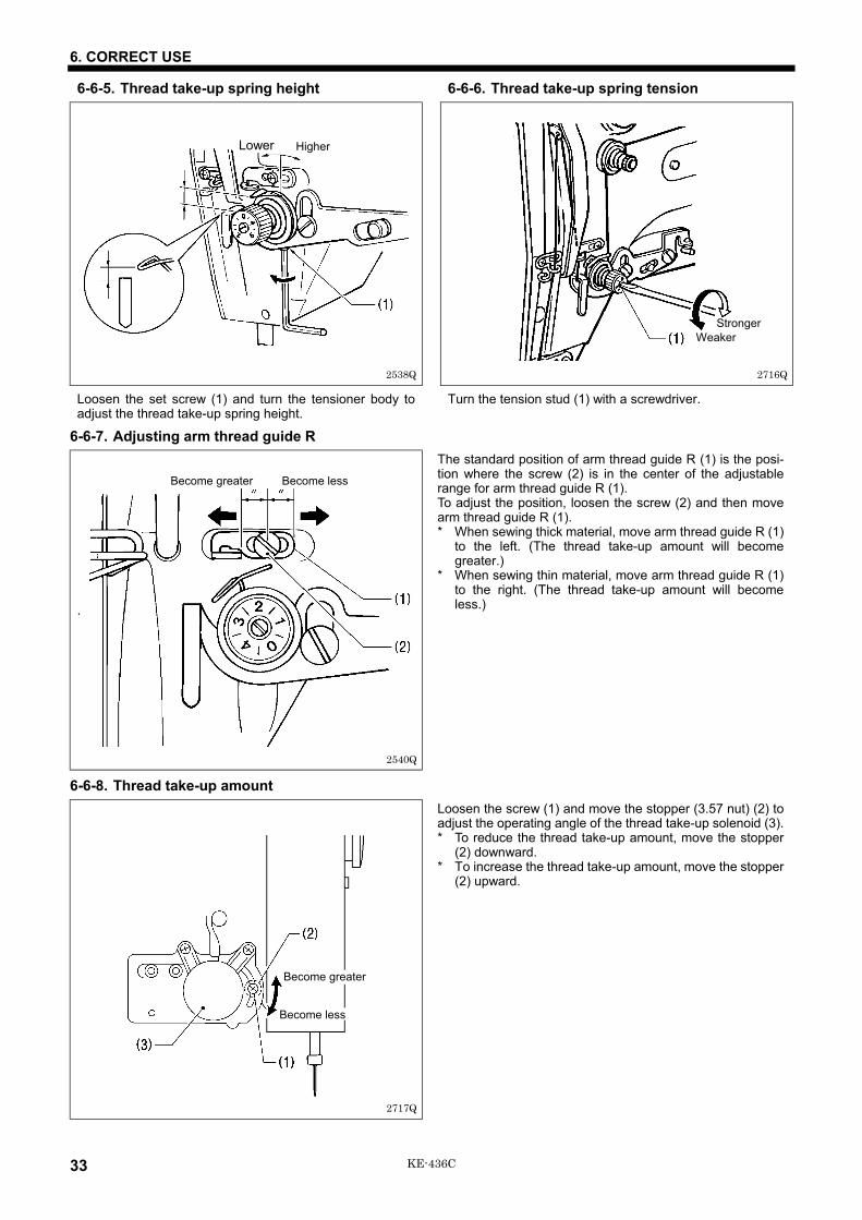
Loosen the set screw (1) and turn the tensioner body toadjust the thread take-up spring height.
Turn the tension stud (1) with a screwdriver.
6-6-7. Adjusting arm thread guide R
.
The standard position of arm thread guide R (1) is the posi-tion where the screw (2) is in the center of the adjustablerange for arm thread guide R (1).To adjust the position, loosen the screw (2) and then movearm thread guide R (1).* When sewing thick material, move arm thread guide R (1)
to the left. (The thread take-up amount will becomegreater.)
* When sewing thin material, move arm thread guide R (1)to the right. (The thread take-up amount will becomeless.)
6-6-8. Thread take-up amountLoosen the screw (1) and move the stopper (3.57 nut) (2) toadjust the operating angle of the thread take-up solenoid (3).* To reduce the thread take-up amount, move the stopper
(2) downward.* To increase the thread take-up amount, move the stopper
(2) upward.
2717Q
Become greater
Become less
2716Q2538Q
Lower Higher
Weaker Stronger
2540Q
Become greater Become less

7. SEWING
34KE-436C
7. SEWING
CAUTIONTurn off the power switch at the following times, otherwise the machine may operate if the foot switch is depressedby mistake, which could result in injury.
• When threading the needle• When replacing the needle and bobbin• When not using the machine and when leaving the machine unattendedDo not touch any of the moving parts or press any objects against the machine while sewing, as this may result inpersonal injury or damage to the machine.
Note:At the time of shipment from the factory, this sewing machine is set to not detect needle up errors. If you would like needleup errors to be detected, set memory switch No. 14 to ON.
7-1. Before starting sewing....Check that the needle bar is at its highest position. Turn themachine pulley so that the index mark (1) on the pulley isbetween the marks (2) on the belt cover.
* If the machine is started while the index mark (1) is notbetween these two marks (2), error message “E.22” willbe displayed.(only when memory switch No.14 is on)
7-2. Sewing operation1. Turn the power switch on.
(The power indicator on the operation panel will light.)2. Insert the floppy disk (1).3. Press the PRO. No. selection switch (2) to select the
desired program number.4. Press R/W switch (3).
• The floppy disk drive indicator will light and theprogram no. display (4) will show a “P” while the data isbeing read. When reading is completed, an alarm willsound and the indicator will go out, then the programno. display (4) will blink the program number.
2719Q2718Q
2462Q

7. SEWING
35 KE-436C
5. Step on the work clamp switch (6) to raise the workclamp.
6. Insert the work piece under the work clamp, and pressthe work clamp switch (6) to lower the clamp.
7. Press the start switch (7).Note:
The work clamp will return to the origin, and will thenadvance to the sewing start position and blinking willstop. This is only required the first time a program issewing.
8. Press the start switch (7) again to start sewing.9. After sewing is completed, the thread cutter will
automatically operate, then the work clamp will rise.
Note:When the power is turned on after once being turned off, the same pattern of sewing can be continued since the machinewill stores the sewing data from the last time.
2720Q
8. MAINTENANCE AND INSPECTION
36KE-436C
8. MAINTENANCE AND INSPECTION
CAUTIONTurn off the power switch before carrying out cleaning, otherwise the machine may operate if the foot switch isdepressed by mistake, which could result in injury.Be sure to wear protective goggles and gloves when handling the lubricating oil and grease, so that they do not getinto your eyes or onto your skin, otherwise inflammation can result.Furthermore, do not drink the oil or eat the grease under any circumstances, as they can cause vomiting anddiarrhoea. Keep the oil out of the reach of children.Wait until the motor has cooled down before cleaning the air holes.The motor may be hot immediately after it has been used, and it may cause burns if touched.
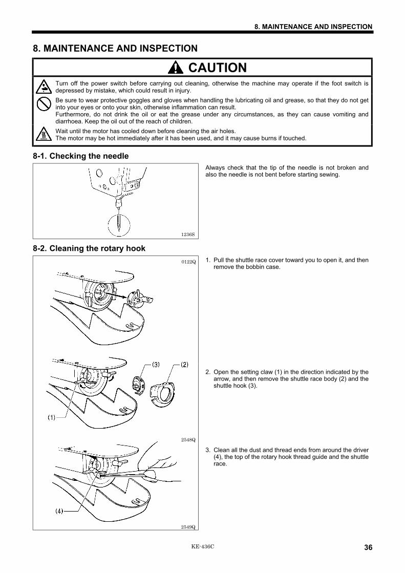
8-1. Checking the needleAlways check that the tip of the needle is not broken andalso the needle is not bent before starting sewing.
8-2. Cleaning the rotary hook1. Pull the shuttle race cover toward you to open it, and then
remove the bobbin case.
2. Open the setting claw (1) in the direction indicated by thearrow, and then remove the shuttle race body (2) and theshuttle hook (3).
3. Clean all the dust and thread ends from around the driver(4), the top of the rotary hook thread guide and the shuttlerace.
0122Q
2548Q
2549Q
1236S
8. MAINTENANCE AND INSPECTION
37 KE-436C
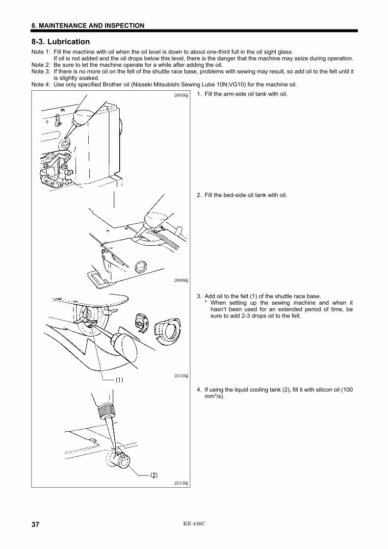
8-3. LubricationNote 1: Fill the machine with oil when the oil level is down to about one-third full in the oil sight glass.
If oil is not added and the oil drops below this level, there is the danger that the machine may seize during operation.Note 2: Be sure to let the machine operate for a while after adding the oil.Note 3: If there is no more oil on the felt of the shuttle race base, problems with sewing may result, so add oil to the felt until it
is slightly soaked.Note 4: Use only specified Brother oil (Nisseki Mitsubishi Sewing Lube 10N;VG10) for the machine oil.
1. Fill the arm-side oil tank with oil.
2. Fill the bed-side oil tank with oil.
3. Add oil to the felt (1) of the shuttle race base.* When setting up the sewing machine and when it
hasn’t been used for an extended period of time, besure to add 2-3 drops oil to the felt.
4. If using the liquid cooling tank (2), fill it with silicon oil (100mm2/s).
2685Q
2686Q
2513Q
2512Q
8. MAINTENANCE AND INSPECTION
38KE-436C
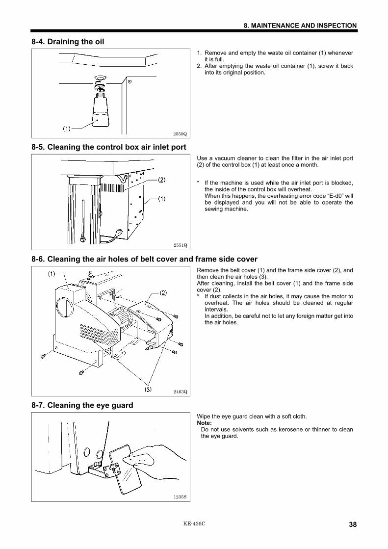
8-4. Draining the oil1. Remove and empty the waste oil container (1) whenever
it is full.2. After emptying the waste oil container (1), screw it back
into its original position.
8-5. Cleaning the control box air inlet portUse a vacuum cleaner to clean the filter in the air inlet port(2) of the control box (1) at least once a month.
* If the machine is used while the air inlet port is blocked,the inside of the control box will overheat.When this happens, the overheating error code “E-d0” willbe displayed and you will not be able to operate thesewing machine.
8-6. Cleaning the air holes of belt cover and frame side coverRemove the belt cover (1) and the frame side cover (2), andthen clean the air holes (3).After cleaning, install the belt cover (1) and the frame sidecover (2).* If dust collects in the air holes, it may cause the motor to
overheat. The air holes should be cleaned at regularintervals.In addition, be careful not to let any foreign matter get intothe air holes.
8-7. Cleaning the eye guardWipe the eye guard clean with a soft cloth.Note:
Do not use solvents such as kerosene or thinner to cleanthe eye guard.
2550Q
2551Q
2463Q
1235S

9. STANDARD ADJUSTMENTS
39 KE-436C
9. STANDARD ADJUSTMENTS
CAUTIONMaintenance and inspection of the sewing machineshould only be carried out by a qualified technician.Ask your Brother dealer or a qualified electrician tocarry out any maintenance and inspection of theelectrical system.Turn off the power switch and disconnect the powercord from the wall outlet at the following times,otherwise the machine may operate if the foot switchis depressed by mistake, which could result in injury.• When carring out inspection, adjustment and
maintenance• When replacing consumable parts such as the
rotary hook and knife
Hold the machine head with both hands when tilting itback or returning it to its original position.Furthermore, after tilting back the machine head, donot push the face plate side or the pulley side fromabove, as this could cause the machine head totopple over, which may result in personal injury ordamage to the machine.If the power switch and air need to be left on whencarrying out some adjustment, be extremely careful toobserve all safety precautions.If any safety devices have been removed, beabsolutely sure to re-install them to their originalpositions and check that they operate correctly beforeusing the machine.
9-1. Adjusting the needle bar height
Turn the machine pulley to move the needle bar to the lowest position. Then remove the rubber plug (2), loosen the set screw(3) and then move the needle bar up or down to adjust so that the second reference line from the bottom of the needle(reference line A) is aligned with the lower edge of the needle bar bush (1).* If using a DP × 5 needle, use the highest reference line (reference line a).
9-2. Adjusting the needle bar lift amount
Turn the machine pulley to raise the needle bar from the lowest position until the lowest reference line on the needle(reference line B) is aligned with the lower edge of the needle bar bush (1). Then loosen the screw (2) and move the driver (3)to adjust so that the tip of the rotary hook is aligned with the needle center line.
* If using a DP × 5 needle, use the second reference line from the top of the needle (reference line b).
2552Q 2721Q
2554Q 2464Q

9. STANDARD ADJUSTMENTS
40KE-436C
9-3. Adjusting the driver needle guard
Turn the machine pulley to align the tip of the rotary hook with the needle center line. Then loosen the set screw (2) and turnthe eccentric shaft (3) to adjust so that the driver needle guard (1) contacts the needle.If the needle contact pressure is too great, skipped stitches may occur. On the other hand, if the driver needle guard (1) is nottouching the needle, the tip of the inner rotary hook will obstruct the needle, resulting in an excessively high amount of friction.
9-4. Adjusting the needle clearance
Turn the machine pulley to align the tip of the rotary hook with the needle center line. Then loosen the set screw (1) and turnthe eccentric shaft (2) to adjust so that the clearance between the needle and the rotary hook is 0.01 - 0.08 mm.
9-5. Adjusting the shuttle race thread guide
Install the shuttle race thread guide (1) by pushing it in the direction of the arrow so that the needle groove is aligned with thecenter of the needle plate hole.Note:
If the shuttle race thread guide is in the wrong position, thread breakages, soiled thread or catching of the thread mayoccur.The position of the shuttle race thread guide is adjusted at the time of shipment from the factory. It should not be changed ifat all possible.
2558Q
Needle center line
Tip
0135Q 2555Q 2556Q
0138Q 2557Q
0.01 - 0.08mm

9. STANDARD ADJUSTMENTS
41 KE-436C
9-6. Adjusting the thread take-up amount
At the time of shipment from the factory, the thread take-up amount (stroke) of the thread take-up lever (1) is set to thestandard setting of 5 mm. You may need to adjust this setting depending on the sewing conditions to prevent the thread frompulling out at the sewing start.Adjustment method
Loosen the screw (2) and move the stopper (3.57 nut) (3) to adjust the operating angle of the thread take-up solenoid (4).* To reduce the thread take-up amount, move the stopper (3) downward.* To increase the thread take-up amount, move the stopper (3) upward.
Note:Do not increase the stroke of the thread take-up lever any more than is necessary.If the sub-thread tension is too high, the needle thread length may become too short and the thread may come out of theneedle. Furthermore, if the sub-thread tension is too weak, the needle thread length may become too long and theunderside of the article being sewn may become untidy.
2722Q2559Q
Thread take-up amount (stroke)
Become greater
Become less

9. STANDARD ADJUSTMENTS
42KE-436C
9-7. Adjusting the movable knife
1. Remove the top cover (1) while making this adjustment.2. Press down on the plunger (2) of the thread trimming solenoid as shown in the illustration, and fit the roller (3) into the
groove of the thread trimmer cam (4).3. In this condition, turn the machine pulley to align the position of the roller (3) with the mark on the thread trimmer cam (4).
4. Loosen the nut (6) and move the connecting rod lever (7) to the left or right to adjust so that the V section AA is aligned withthe index mark BB on the needle plate when in this condition (the procedure 3.) and the movable knife (5) is pushed to themachine pulley side so that there is no play.
2723Q 2561Q
Mark
2562Q 2563Q

9. STANDARD ADJUSTMENTS
43 KE-436C
9-7-1. Replacing the movable knife and fixed knife
1. Open the large shuttle hook cover, remove the bolts (1) and the feed plate (2).2. Remove the two screws (3) and the two screws (4), and then remove the needle plate (5).3. Remove the thread trimmer connecting rod (6) from the connecting rod lever pin (7).
4. Remove the movable knife (8) and replace it with a new one. At this time, check that the movable knife (8) and the fixedknife (9) cut the thread cleanly. If necessary, adjust by using the appropriate movable knife washer (10) (supplied asaccessories).* Apply grease to the outside of the collar (11) at this time.
5. Install the fixed knife (9) at a distance of 0.5 mm from the needle hole plate (12).6. Place the thread trimming connecting rod (6) onto the connecting rod lever pin (7), and then install to the needle plate (5).
2615Q 2485Q
2946Q 2947Q
9. STANDARD ADJUSTMENTS
44KE-436C
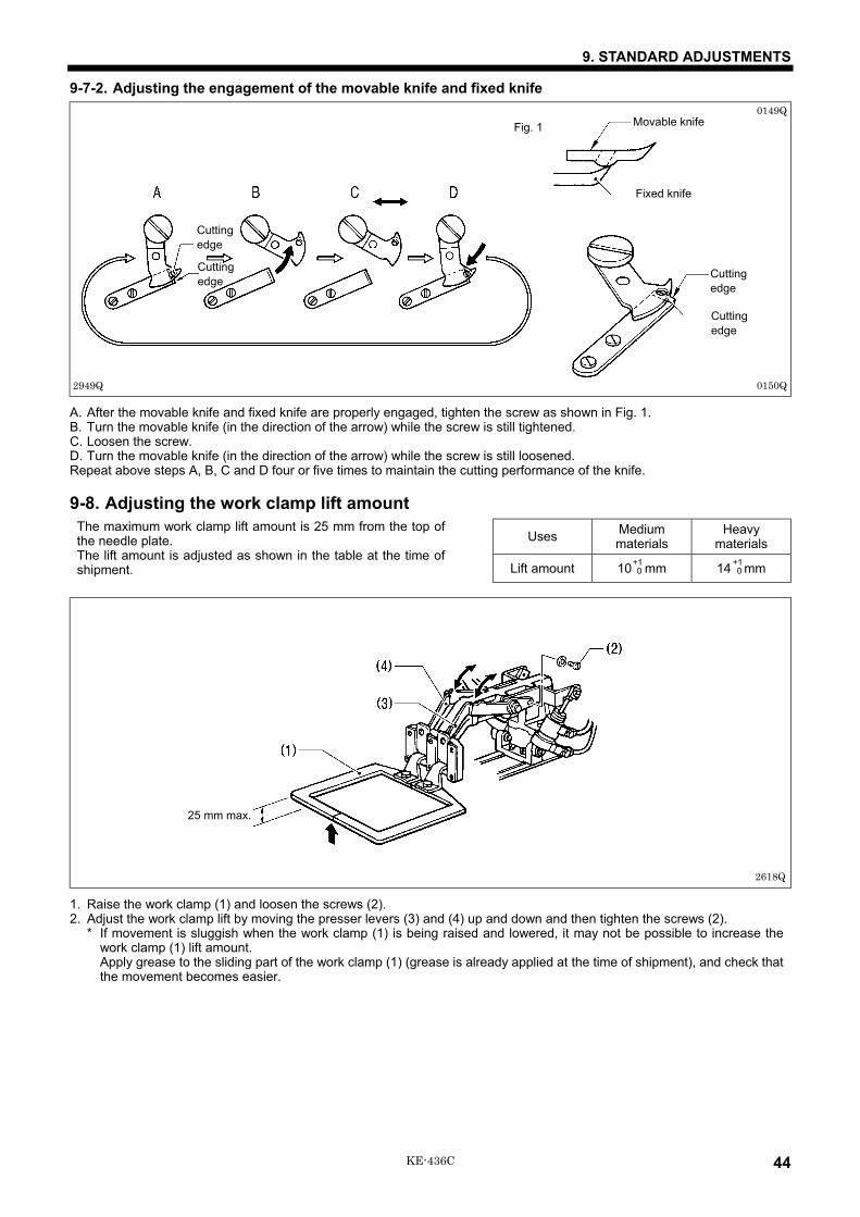
9-7-2. Adjusting the engagement of the movable knife and fixed knife
A. After the movable knife and fixed knife are properly engaged, tighten the screw as shown in Fig. 1.B. Turn the movable knife (in the direction of the arrow) while the screw is still tightened.C. Loosen the screw.D. Turn the movable knife (in the direction of the arrow) while the screw is still loosened.Repeat above steps A, B, C and D four or five times to maintain the cutting performance of the knife.
9-8. Adjusting the work clamp lift amount
Uses Mediummaterials
Heavymaterials
The maximum work clamp lift amount is 25 mm from the top ofthe needle plate.The lift amount is adjusted as shown in the table at the time ofshipment. Lift amount 10 mm 14 mm
1. Raise the work clamp (1) and loosen the screws (2).2. Adjust the work clamp lift by moving the presser levers (3) and (4) up and down and then tighten the screws (2).
* If movement is sluggish when the work clamp (1) is being raised and lowered, it may not be possible to increase thework clamp (1) lift amount.Apply grease to the sliding part of the work clamp (1) (grease is already applied at the time of shipment), and check thatthe movement becomes easier.
+1 0
+1 0
2618Q
25 mm max.
0149QFig. 1 Movable knife
Fixed knife
0150Q
Cuttingedge
Cuttingedge
2949Q
Cuttingedge
Cuttingedge

9. STANDARD ADJUSTMENTS
45 KE-436C
9-9. Work clamp adjustmentTurn the pulley to hand to lower the work clamp to the down position, and then proceed with the steps below.
1. Loosen screw (1), set the bottom of the work clamp (2)lightly against the work piece, and then tighten screw (1).Note:
If the work clamp is lowered too far, the work piece willshift when sewing. Also, if the work clamp is too high,skipped stitches may occur.
2. Turn the pulley by hand, and make sure the needle entersthe center of the needle hole in the work clamp (2). If theneedle is not aligned with the center of the needle hole,remove cap (3), loosen screw (4), and turn the work camp(presser bar) to adjust.
9-10. Changing the work clamp liftStandard work clamp (1) lift is 3 mm (max. 8 mm).
Adjusting work clamp lift to 3 - 5 mm1. Loosen the screw (2) and open the stepping cover (3).2. Loosen the nut (4) and adjust the stepping work clamp connecting rod (5) position.
* When the stepping work clamp connecting rod is raised, the lift will increase. When lowered, the lift will decrease.Adjusting work clamp lift to 5 - 8 mm
1. Turn the upper shaft to set the work clamp to its lowest point. Loosen the screw (9) of stepping work clamp arm (R) (8).Adjust the clearance between the presser bar lifter (6) and the presser bar bush (7) to 0.5 - 1 mm.
2. Loosen the nut (4) and adjust the stepping work clamp connecting rod (5) position.* When the stepping work clamp connecting rod is raised, the lift will increase. When lowered, the lift will decrease.
If vertical movement of the work clamp is not required1. Remove the face plate (10).2. Remove the stud screw (11) and re-attach the stepping
connecting rod (12) to the upper screw hole (14) of thestepping work clamp arm (F) (13).
2625Q
2627Q2626Q
3 - 5mmIncrease
Decrease
2483Q
0.5 - 1mm
2628Q 2629Q
9. STANDARD ADJUSTMENTS
46KE-436C
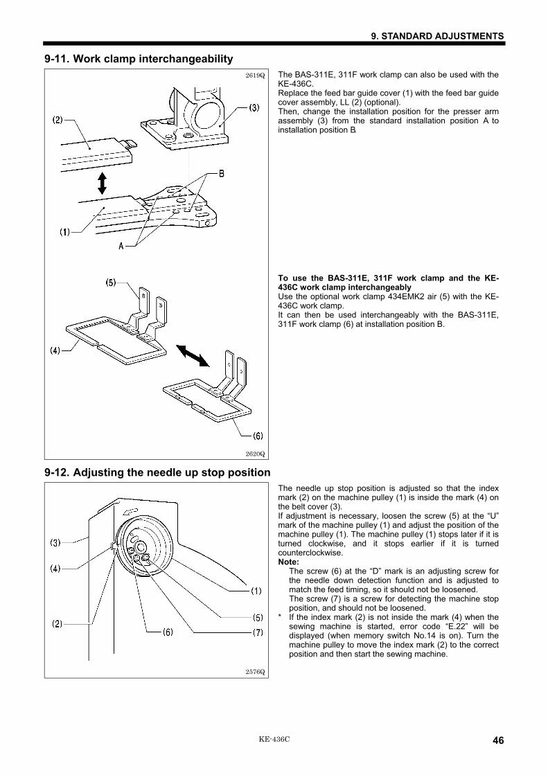
9-11. Work clamp interchangeabilityThe BAS-311E, 311F work clamp can also be used with theKE-436C.Replace the feed bar guide cover (1) with the feed bar guidecover assembly, LL (2) (optional).Then, change the installation position for the presser armassembly (3) from the standard installation position A toinstallation position B.
To use the BAS-311E, 311F work clamp and the KE-436C work clamp interchangeablyUse the optional work clamp 434EMK2 air (5) with the KE-436C work clamp.It can then be used interchangeably with the BAS-311E,311F work clamp (6) at installation position B.
9-12. Adjusting the needle up stop positionThe needle up stop position is adjusted so that the indexmark (2) on the machine pulley (1) is inside the mark (4) onthe belt cover (3).If adjustment is necessary, loosen the screw (5) at the “U”mark of the machine pulley (1) and adjust the position of themachine pulley (1). The machine pulley (1) stops later if it isturned clockwise, and it stops earlier if it is turnedcounterclockwise.Note:
The screw (6) at the “D” mark is an adjusting screw forthe needle down detection function and is adjusted tomatch the feed timing, so it should not be loosened.The screw (7) is a screw for detecting the machine stopposition, and should not be loosened.
* If the index mark (2) is not inside the mark (4) when thesewing machine is started, error code “E.22” will bedisplayed (when memory switch No.14 is on). Turn themachine pulley to move the index mark (2) to the correctposition and then start the sewing machine.
2620Q
2619Q
2576Q
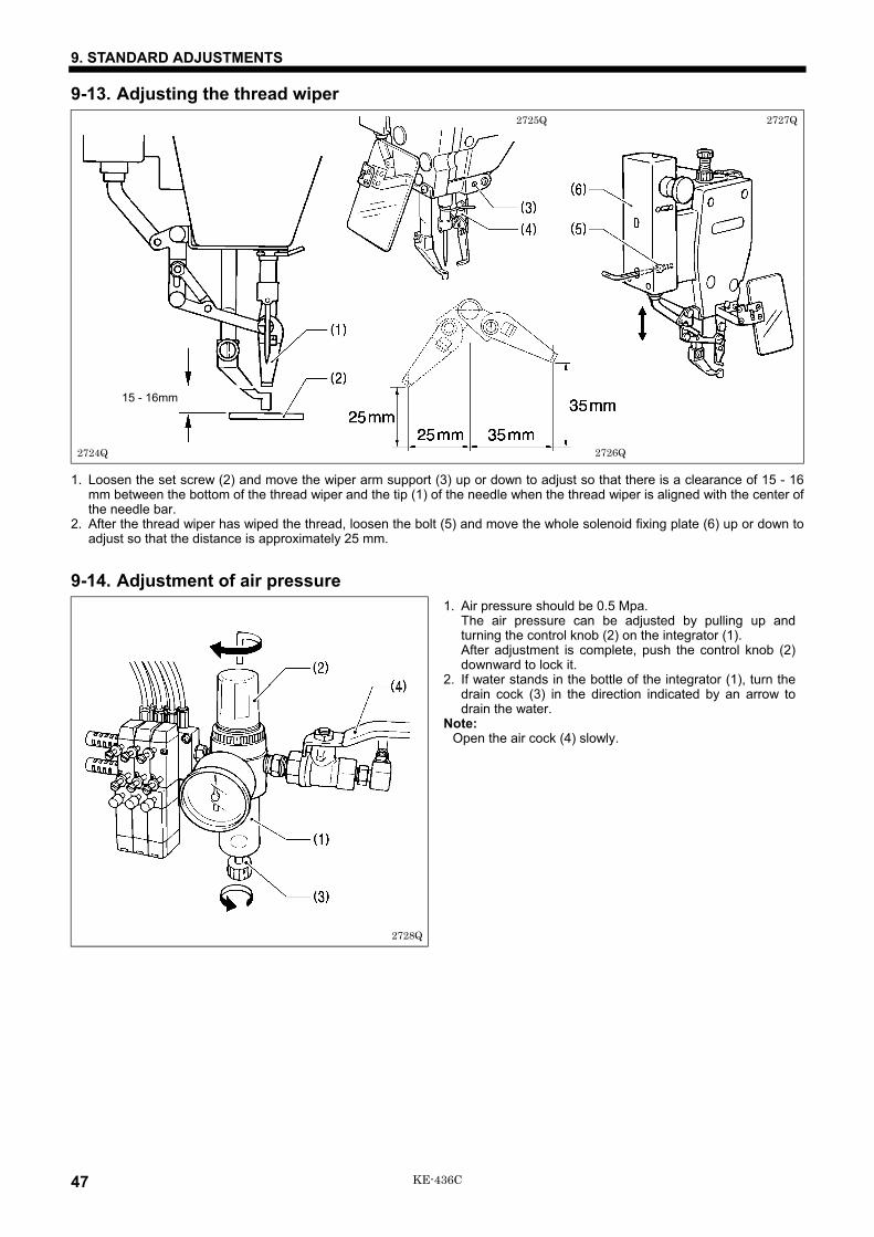
9. STANDARD ADJUSTMENTS
47 KE-436C
9-13. Adjusting the thread wiper
1. Loosen the set screw (2) and move the wiper arm support (3) up or down to adjust so that there is a clearance of 15 - 16mm between the bottom of the thread wiper and the tip (1) of the needle when the thread wiper is aligned with the center ofthe needle bar.
2. After the thread wiper has wiped the thread, loosen the bolt (5) and move the whole solenoid fixing plate (6) up or down toadjust so that the distance is approximately 25 mm.
9-14. Adjustment of air pressure1. Air pressure should be 0.5 Mpa.
The air pressure can be adjusted by pulling up andturning the control knob (2) on the integrator (1).After adjustment is complete, push the control knob (2)downward to lock it.
2. If water stands in the bottle of the integrator (1), turn thedrain cock (3) in the direction indicated by an arrow todrain the water.
Note:Open the air cock (4) slowly.
2724Q
2727Q
15 - 16mm
2725Q
2726Q
2728Q
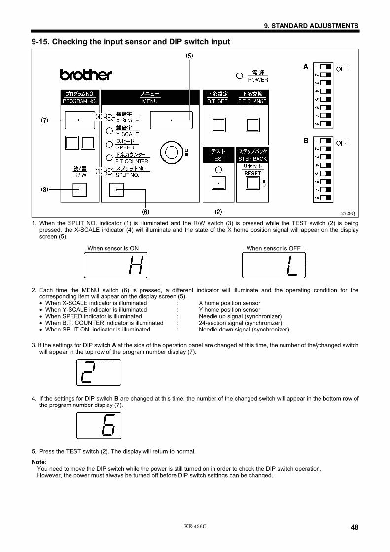
9. STANDARD ADJUSTMENTS
48KE-436C
9-15. Checking the input sensor and DIP switch input
1. When the SPLIT NO. indicator (1) is illuminated and the R/W switch (3) is pressed while the TEST switch (2) is beingpressed, the X-SCALE indicator (4) will illuminate and the state of the X home position signal will appear on the displayscreen (5).
When sensor is ON When sensor is OFF
2. Each time the MENU switch (6) is pressed, a different indicator will illuminate and the operating condition for thecorresponding item will appear on the display screen (5).• When X-SCALE indicator is illuminated : X home position sensor• When Y-SCALE indicator is illuminated : Y home position sensor• When SPEED indicator is illuminated : Needle up signal (synchronizer)• When B.T. COUNTER indicator is illuminated : 24-section signal (synchronizer)• When SPLIT ON. indicator is illuminated : Needle down signal (synchronizer)
3. If the settings for DIP switch A at the side of the operation panel are changed at this time, the number of they̌changed switchwill appear in the top row of the program number display (7).
4. If the settings for DIP switch B are changed at this time, the number of the changed switch will appear in the bottom row ofthe program number display (7).
5. Press the TEST switch (2). The display will return to normal.
Note:You need to move the DIP switch while the power is still turned on in order to check the DIP switch operation.However, the power must always be turned off before DIP switch settings can be changed.
2729Q

9. STANDARD ADJUSTMENTS
49 KE-436C
9-16. Checking the input voltage1. Turn on the power switch.2. Press the menu switch (1) until the X-SCALE indicator (2) illuminates.
3. While pressing the TEST switch (3), press the R/W switch (4).
4. If the input voltage is normal, the input voltage conditions will be shown in the display as indicated in the table below.
200-V specifications 090 - 110
220-V specifications 100 - 120“100” is displayed when the input voltage is 200 V.
230-V specifications 105 - 125
100-V, 380-V, 400-V 100 - 120
“110” is displayed when the input voltage is100 V (for 100-V specs.), 380 V (for 380-V specs.),400 V (for 400-V specs.).
5. Press the TEST switch (3) once more to return the display to the normal condition.
9-17. Clearing all memory settingsIf the sewing machine stops operating normally, the cause may be that an incorrect memory setting may have been made bymeans of the memory switch, for instance. In such cases, carry out the following procedure to clear the memory, and alsocheck the DIP switch settings.While pressing the R/W switch (1), turn on the power. This will clear all of the memory setting.Note:
This operation causes memory switch settings to be returned to their initial settings, and also clears all contents of thememory such as user programs.
2730Q
2731Q
2732Q

10. DIP SWITCH
50KE-436C
10. DIP SWITCHNote:
When changing DIP switch, the power must be off.
10-1. Panel DIP switch functions
DIP switch A
Switch Motion when set to ON
DIPA-1 Presser does not automatically lift after sewingis completed.
DIPA-2 Pedal mode is switched.
See “12. Setting the pressermode”
DIPA-3 −
DIPA-4 −
DIPA-5 After sewing is completed, work clamp does not automatically rise. (only in split mode)
DIPA-6 Clamping force output is produced. (Inner clamping device available as an option)
DIPA-7 −
DIPA-8 Thread breakage detector device is activated (available as an option).
DIP switch B
Switch Motion when set to ON
DIPB-1 Single split mode activated
DIPB-2 −
DIPB-3 Thread is not trimmed after an emergency stop.
DIPB-4 Needle cooler output is produced. (Needle cooler available as an option)
DIPB-5
When a rotating-type thread breakage detector device is used, detection precision is increasedfrom 8 to 14.When a fiber-type thread breakage detector device is used, detection precision is increasedfrom 5 to 10.
DIPB-6 Fiber-type thread breakage detector device is ON, and DIP switch A-8 is ON (available as anoption).
DIPB-7 −
DIPB-8 −
1086Q
All DIP switches are set to OFF at the time of shipment.
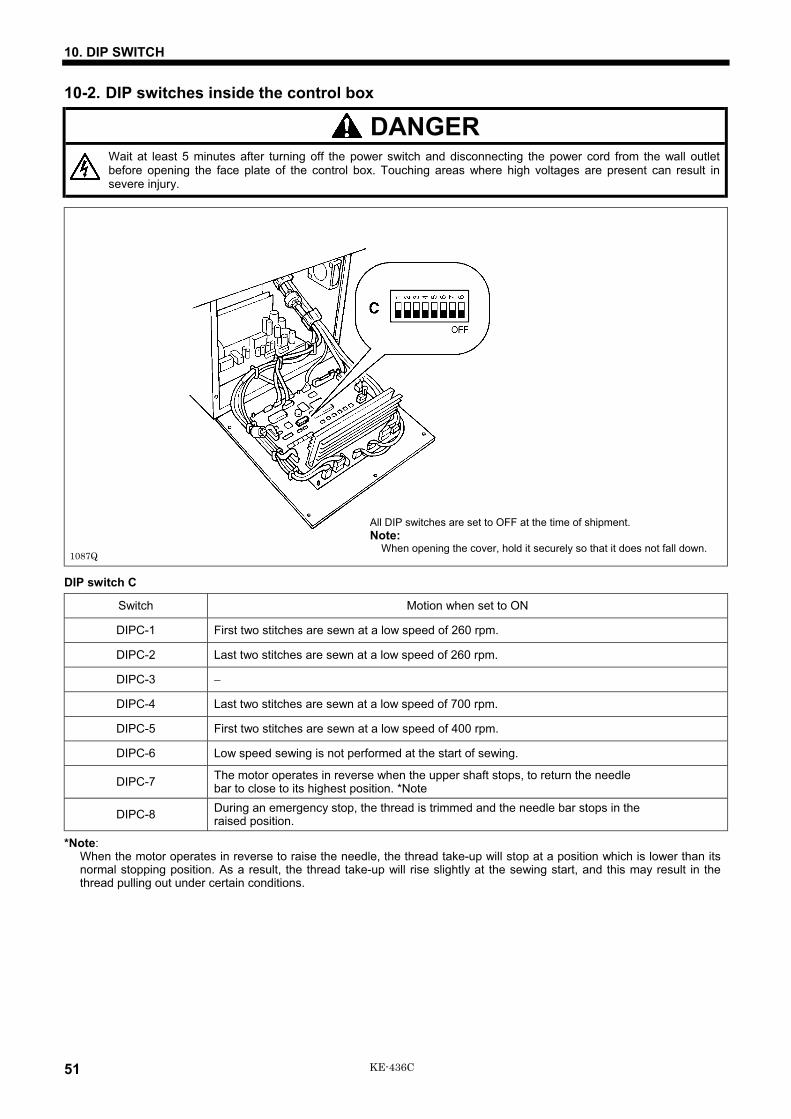
10. DIP SWITCH
51 KE-436C
10-2. DIP switches inside the control box
DANGERWait at least 5 minutes after turning off the power switch and disconnecting the power cord from the wall outletbefore opening the face plate of the control box. Touching areas where high voltages are present can result insevere injury.
DIP switch C
Switch Motion when set to ON
DIPC-1 First two stitches are sewn at a low speed of 260 rpm.
DIPC-2 Last two stitches are sewn at a low speed of 260 rpm.
DIPC-3 −
DIPC-4 Last two stitches are sewn at a low speed of 700 rpm.
DIPC-5 First two stitches are sewn at a low speed of 400 rpm.
DIPC-6 Low speed sewing is not performed at the start of sewing.
DIPC-7 The motor operates in reverse when the upper shaft stops, to return the needlebar to close to its highest position. *Note
DIPC-8 During an emergency stop, the thread is trimmed and the needle bar stops in theraised position.
*Note:When the motor operates in reverse to raise the needle, the thread take-up will stop at a position which is lower than itsnormal stopping position. As a result, the thread take-up will rise slightly at the sewing start, and this may result in thethread pulling out under certain conditions.
1087Q
All DIP switches are set to OFF at the time of shipment.Note:
When opening the cover, hold it securely so that it does not fall down.

11. CHANGING SPECIAL FUNCTIONS USING THE MEMORY SWITCHES
52KE-436C
11. CHANGING SPECIAL FUNCTIONS USING THE MEMORY SWITCHESThe functions of the switches on the operation panel can be changed to carry out special functions.Note:
After changing the memory switch settings, press the power switch to turn the power off and then back on again.
1. Turn on the power switch.2. While pressing the TEST switch (1), press the STEP BACK switch (2) to switch to setting mode.3. Press the program select switch (4) so that the number displayed on the display screen (3) matches the switch number (00 -
3F) for the function that you would like to select from the table.4. Press the STEP BACK switch (2) to switch the setting appearing in the display screen (5) from OFF to ON.
If pressed once more:
If the B.T. CHANGE switch (6) is pressed at this time, all memory switch settings will be changed to OFF.5. Press the TEST switch (1). The display will return to normal.Note:
The following steps set the memory switch settings separately for each program number.6. Once the program data has been read from the floppy disk, change to memory switch setting mode and then press the B.T.
SET switch (7). The buzzer will sound twice, and the current memory switch settings will be written to the floppy disk.
2733Q
1287S
1286S
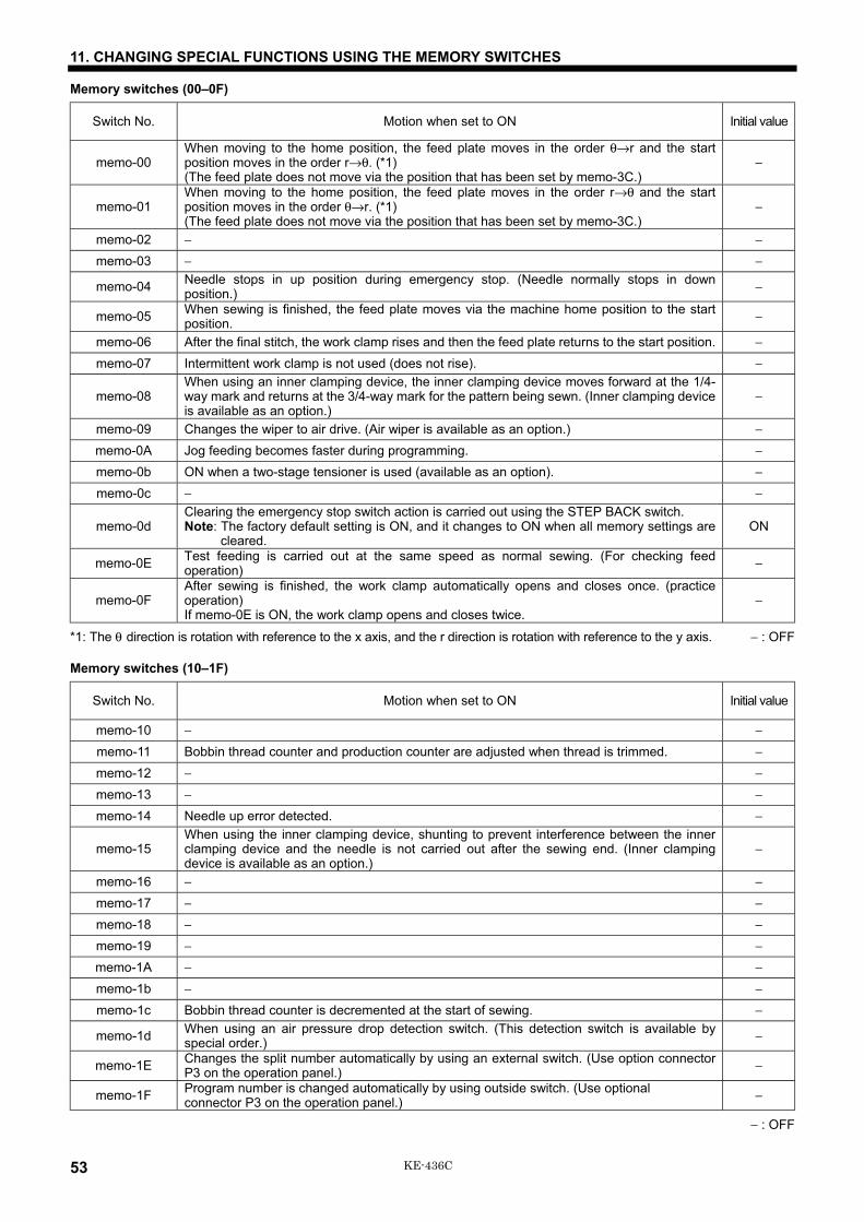
11. CHANGING SPECIAL FUNCTIONS USING THE MEMORY SWITCHES
53 KE-436C
Memory switches (00–0F)
Switch No. Motion when set to ON Initial value
memo-00When moving to the home position, the feed plate moves in the order θ→r and the startposition moves in the order r→θ. (*1)(The feed plate does not move via the position that has been set by memo-3C.)
−
memo-01When moving to the home position, the feed plate moves in the order r→θ and the startposition moves in the order θ→r. (*1)(The feed plate does not move via the position that has been set by memo-3C.)
−
memo-02 − −
memo-03 − −
memo-04 Needle stops in up position during emergency stop. (Needle normally stops in downposition.) −
memo-05 When sewing is finished, the feed plate moves via the machine home position to the startposition. −
memo-06 After the final stitch, the work clamp rises and then the feed plate returns to the start position. −
memo-07 Intermittent work clamp is not used (does not rise). −
memo-08When using an inner clamping device, the inner clamping device moves forward at the 1/4-way mark and returns at the 3/4-way mark for the pattern being sewn. (Inner clamping deviceis available as an option.)
−
memo-09 Changes the wiper to air drive. (Air wiper is available as an option.) −
memo-0A Jog feeding becomes faster during programming. −
memo-0b ON when a two-stage tensioner is used (available as an option). −
memo-0c − −
memo-0dClearing the emergency stop switch action is carried out using the STEP BACK switch.Note: The factory default setting is ON, and it changes to ON when all memory settings are
cleared.ON
memo-0E Test feeding is carried out at the same speed as normal sewing. (For checking feedoperation) −
memo-0FAfter sewing is finished, the work clamp automatically opens and closes once. (practiceoperation)If memo-0E is ON, the work clamp opens and closes twice.
−
*1: The θ direction is rotation with reference to the x axis, and the r direction is rotation with reference to the y axis. − : OFF
Memory switches (10–1F)
Switch No. Motion when set to ON Initial value
memo-10 − −
memo-11 Bobbin thread counter and production counter are adjusted when thread is trimmed. −
memo-12 − −
memo-13 − −
memo-14 Needle up error detected. −
memo-15When using the inner clamping device, shunting to prevent interference between the innerclamping device and the needle is not carried out after the sewing end. (Inner clampingdevice is available as an option.)
−
memo-16 − −
memo-17 − −
memo-18 − −
memo-19 − −
memo-1A − −
memo-1b − −
memo-1c Bobbin thread counter is decremented at the start of sewing. −
memo-1d When using an air pressure drop detection switch. (This detection switch is available byspecial order.) −
memo-1E Changes the split number automatically by using an external switch. (Use option connectorP3 on the operation panel.) −
memo-1F Program number is changed automatically by using outside switch. (Use optionalconnector P3 on the operation panel.) −
− : OFF

11. CHANGING SPECIAL FUNCTIONS USING THE MEMORY SWITCHES
54KE-436C
Memory switches (20 - 2F)
Switch No. Motion when set to ON Initial value
memo-20 During feed test operation, jump feeding 100 stitches at a time is possible using the STEPBACK switch. −
memo-21 After the home position is detected and the machine moves to the sewing start position, thework clamp rises automatically. −
memo-22 − −
memo-23 − −
memo-24 − −
memo-25 The enlargement and reduction ratio settings at the operation panel are fixed at the valueswhen memo-25 was set to ON. −
memo-26 Thread trimming is not carried out. −
memo-27 The sewing speed setting at the opration panel is fixed at the value when memo-27 was setto ON. −
memo-28 Set to ON when using the thread take-up device. ONmemo-29 Work clamp lifting and lower thread winding before home position detection are disabled. −
memo-2A − −
memo-2b − −
memo-2c − −
memo-2d − −
memo-2E − −
memo-2F When the input voltage is being checked, the display shows the temperature of the heat sinkon the main circuit board instead of the voltage. −
− : OFF

11. CHANGING SPECIAL FUNCTIONS USING THE MEMORY SWITCHES
55 KE-436C
Memory switches (30 - 3F)Turn the dial while pressing the STEP BACK switch to change the values.
Switch No. Possible setting range Units Initial value Explanation
memo-30 1 - 999 × 10ms 10 Time until feed mechanism starts moving after work clamphas lifted.
memo-31 1 - 5 − 4 Changes the feed speed.1 (Fast) ←→ 5 (Slow)
memo-32 3 - 7 − 3
Changes the possible sewing speed for a given stitch length.3 (Fast) ←→ 7 (Slow)3 (2,500/3 mm), 4 (2,300/3 mm), 5 (2,000/3 mm),6 (1,800/3 mm), 7 (1,200/3 mm)
memo-33 1 - 10 × 7.5° 5 Changes the feed timing.1 (Fast) ← 5 (Standard) → 10 (Slow)
memo-34 1 - 5 stitch 1 Number of low-speed stitches sewn at 400 rpm at sewingstart.
memo-35 3 - 9 × 100rpm 4 Changes the sewing start speed for the number of stitchesspecified by memo-34.
memo-36 − − − −
memo-37 0 - 3 − 0
Automatically corrects the gear speed when reading 2DDdisks.0: No automatic correction1: Read as BAS-311A data2: Read as BAS-326A data3: Read as BAS-341A, 342A dataex. Read BAS-326A data by KE-436C → Set memo-37=2.
memo-38 − − − −
memo-39 0 - 11 − 0
Changes the reference point for enlargement and reductionusing the operation panel.0, 1: Center of work clamp,2: Upper-left corner of work clamp,3: Lower-left corner of work clamp,4: Upper-right corner of work clamp,5: Lower-right corner of work clamp, 6: Sewing start point,7: Sewing end point, 8: Upper-left corner of sewing pattern,9: Lower-left corner of sewing pattern,10: Upper-right corner of sewing pattern,11: Lower-right corner of sewing pattern
memo-3A 1 - 3 − 2
Changes the speed limit for the given sewing pitch when themaximum speed remains constant.1: Speed limit is increased for the given sewing pitch and the
sewing speed for that pitch is increased.2: Standard3: Speed limit is decreased for the given sewing pitch and the
sewing speed for thet pitch is decreased.Note:If sewing slippage occurs in places where a large sewingpitch is used, reduce the setting to 3.Furthermore, sewing slippage may occur in some cases ifsetting 1 is used.
memo-3b 0 - 13 − 0
Changes the work clamp operating mode. (When set to “0”,the mode is selected according to the settings for DIPswitches A-1 and A-2.) Refer to “12. Setting the work clampmode” for details on the setting values.
memo-3c 0 - 4 − 0
Changes the path taken when moving from the machinehome position to the start position.0: Across inside of work clamp, 1: Top-left, 2: Bottom-left,3: Bottom-right, 4: Top-right
memo-3d − − − −
memo-3E − − − −
memo-3F − − − −

12. SETTING THE WORK CLAMP MODE
56KE-436C
12. SETTING THE WORK CLAMP MODEThrough the combination of DIP switches A-1 and A-2 on the operation panel, presser motions can be set as follows:When memo-3b = 0 (initial value)
DIPA-1 DIPA-2 Pedal specifications Raising the presser at the sewing end
− − Two pedals Presser is raised automatically, then it is lowered by pressing thepedal. (factory default settings)
ON − Two pedals Presser is kept lifted while the presser pedal is pressed.
− ON Single pedal Presser is raised automatically.
ON ON Single pedal Presser is raised by pressing the pedal.
Special memo-3b settings for pneumatic specifications
memo-3b Pedal specifications Raising the presser at the sewing end
5 Two pedals
Left presser drops when presser pedal is at the 1st step, and right presser dropswhen presser pedal is at the 2nd step.Raising is carried out in the reverse order.* Setting used when using the light work clamp function (Refer to “12-1. Light work
clamp”.)
6 Two pedalsRight presser drops when presser pedal is at the 1st step, and left presser dropswhen presser pedal is at the 2nd step.Raising is carried out in the reverse order.
7 Two pedalsThe left/right operating sequence changes alternately for each item sewn whenusing two-pedal operation.Starts with right → left.
8 Three pedals(Option)
The left pedal is used to raise and lower the left presser, and the right (center) pedalis used to raise and lower the right presser.The start (right) pedal is used to start sewing.Furthermore, when DIP switch A-2 is at ON, and if one presser is already lowered,pressing the start pedal causes the other presser to be lowered and then sewingstarts.
9 Two pedalsWhen the presser pedal is depressed to the 1st step, both left and right pressers areraised simultaneously.When it is pressed to the 2nd step, sewing starts.
10 Two pedalsWhen the start pedal is depressed, both left and right pressers are loweredsimultaneously.When the start pedal is released, sewing starts.
11 Three pedals(Option)
The left pedal raises and lowers the left and right work clamps, and the right pedal(center) detects the home position.The start (right) pedal is used to start sewing.Furthermore, both work clamps are lowered when DIP switch A-2 is ON, and thestepping foot is also lowered at the same time.
12 Three pedals(Option)
The left pedal raises and lowers the left work clamp, and the right pedal (center)detects the home position.When the start pedal (right side) is depressed for a short time (200 ms), the rightwork clamp is lowered, and when it is depressed for a longer time the right workclamp is lowered and then sewing starts.Furthermore, the right work clamp is lowered when DIP switch A-2 is ON, and thestepping foot is also lowered at the same time.
13 Two pedals Two-pedal operation raises and lowers the left and right work clampssimultaneously, and the stepping foot is lowered at the sewing start.
When memo-3b has been used to make a special setting, DIP switches A-1 and A-2 function as follows.• When DIP switch A-1 is at ON, the pressers are not raised automatically at the sewing end.• DIP switch A-2 is ignored except when memo-3b = 8, 11, 12.

12. SETTING THE WORK CLAMP MODE
57 KE-436C
12-1. Light work clampFor pneumatic specifications, the hose connections can be changed so that the pressers are made to lower gently when thepresser pedal is depressed to the 1st step, and firmly when the presser pedal is depressed to the 2nd step. This makes iteasier to carry out position matching when attaching small articles such as labels.[Memory switch setting]Set memo-3b to 5 for two-pedal mode so that the pressers lower in the order of left then right for the standard hoseconnection. (Refer to “11. Changing special functions using the memory switches”.)< Hose connections for light work clamp operation by both pressers >
[How to use]1. Depress the presser pedal to the 1st step to lower the pressers and apply a light pressure. You can then position small
articles such as labels at this time.2. After checking that everything is positioned correctly, depress the presser pedal to the 2nd step to firmly clamp the article
being sewn.3. Press the start pedal to start sewing.<Other hose connections and corresponding operations>The hoses can be connected in combinations other than the one shown above so that only one side of the presser operatesin light work clamp mode.
Cylinder connectorsBranch and plugconnectors A B C D
Operation when presser pedal is depressed to the 1st step
Branch: 1B, 2APlug: 1A, 2B 1B 2A 1B 2A
Both pressers operate in light work clamp mode(example shown above)
Branch: 1BPlug: 2B 1B 2A 1B 1A Only left presser lowers, and it lowers in light work clamp mode
Branch: 1BPlug: 2B 1B 1A 1B 2A
Only right presser lowers , and it lowers in light work clampmode
Branch: 2APlug: 1A 1B 2A 2B 2A
Both pressers lower, but only left presser lowers in light workclamp mode
Branch: 2APlug: 1A 2B 2A 1B 2A
Both pressers lower, but only right presser lowers in light workclamp mode
1088Q
Branch
Plug

13. TABLE OF ERROR CODES
58KE-436C
13. TABLE OF ERROR CODES
DANGERWait at least 5 minutes after turning off the power switch and disconnecting the power cord from the wall outletbefore opening the face plate of the control box. Touching areas where high voltages are present can result insevere injury.
If a malfunction should occur with the sewing machine, a buzzer will sound and an error code will appear in the displaywindow. Follow the remedy procedure to eliminate the cause of the problem.
Code Cause Remedy
E.10 Emergency stop switch was pressed.Turn the EMERGENCY STOP switch clockwise to releasethe lock, and then press the STEP BACK (RESET) switchto reset the error.
E.11 Emergency stop switch was pressed duringsewing.
Turn the EMERGENCY STOP switch clockwise to releasethe lock, and then press the STEP BACK (RESET) switchto reset the error. You can then press the STEP BACK(RESET) switch to repeat the sewing.
E.12 Emergency stop switch is activated or itsconnection is not correct. Turn off power and check it.
E.13 Defective connection of model selectionconnector. Turn off power and check connector P3.
E.14 Foot switch was depressed, or connection of footswitch is defective. Turn off power and check it.
E.15 Start switch was depressed, or connection of startswitch is defective. Turn off power and check it.
E.16 Machine head was tilted back. Turn off power and tilt machine head back.
E.17 Operation panel switch was depressed whenpower was turned on. Turn off power and check it.
E.20Motor malfunctions or synchronizer is notconnected correctly. Or thermostat inside sewingmachine motor has operated.
Turn off power, and then turn the machine pulley to checkif the machine has locked up. Check the synchronizerconnection, and connectors P11, P12 and P13.Check if the sewing machine motor has overheated.
E.21 Motor malfunctioned. Turn off power and check ground wire connection.
E.22 Needle up stop position error. Turn pulley to align timing mark with that on belt cover.
E.30 Data exceeds available sewing area due to resizeratio. Adjust resize ratio.
E.31 Stitch length exceeds 10mm due to resize ratio. Adjust resize ratio.
E.32 No end code in sewing data. Input end code, or change program No.
E.40 Floppy disk is not inserted or operation panelcable is not securely connected.
Insert a floppy disk. If floppy disk is already inserted, turnoff the power and check the connections of cords insidethe operation panel.
E.41 Invalid program No., or no data. Change program No.
E.43 Different floppy disk! Use original floppy disk.
E.4F Error occurred during floppy disk data reading. Replace the floppy disk and repeat the operation.
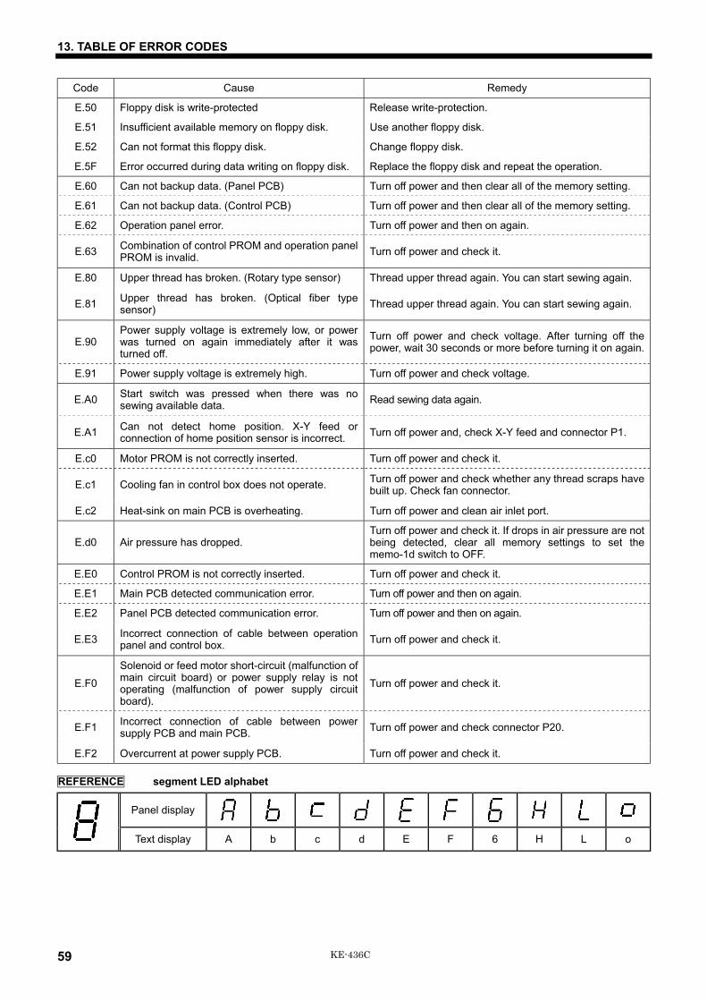
13. TABLE OF ERROR CODES
59 KE-436C
Code Cause Remedy
E.50 Floppy disk is write-protected Release write-protection.
E.51 Insufficient available memory on floppy disk. Use another floppy disk.
E.52 Can not format this floppy disk. Change floppy disk.
E.5F Error occurred during data writing on floppy disk. Replace the floppy disk and repeat the operation.
E.60 Can not backup data. (Panel PCB) Turn off power and then clear all of the memory setting.
E.61 Can not backup data. (Control PCB) Turn off power and then clear all of the memory setting.
E.62 Operation panel error. Turn off power and then on again.
E.63 Combination of control PROM and operation panelPROM is invalid. Turn off power and check it.
E.80 Upper thread has broken. (Rotary type sensor) Thread upper thread again. You can start sewing again.
E.81 Upper thread has broken. (Optical fiber typesensor) Thread upper thread again. You can start sewing again.
E.90Power supply voltage is extremely low, or powerwas turned on again immediately after it wasturned off.
Turn off power and check voltage. After turning off thepower, wait 30 seconds or more before turning it on again.
E.91 Power supply voltage is extremely high. Turn off power and check voltage.
E.A0 Start switch was pressed when there was nosewing available data. Read sewing data again.
E.A1 Can not detect home position. X-Y feed orconnection of home position sensor is incorrect. Turn off power and, check X-Y feed and connector P1.
E.c0 Motor PROM is not correctly inserted. Turn off power and check it.
E.c1 Cooling fan in control box does not operate. Turn off power and check whether any thread scraps havebuilt up. Check fan connector.
E.c2 Heat-sink on main PCB is overheating. Turn off power and clean air inlet port.
E.d0 Air pressure has dropped.Turn off power and check it. If drops in air pressure are notbeing detected, clear all memory settings to set thememo-1d switch to OFF.
E.E0 Control PROM is not correctly inserted. Turn off power and check it.
E.E1 Main PCB detected communication error. Turn off power and then on again.
E.E2 Panel PCB detected communication error. Turn off power and then on again.
E.E3 Incorrect connection of cable between operationpanel and control box. Turn off power and check it.
E.F0
Solenoid or feed motor short-circuit (malfunction ofmain circuit board) or power supply relay is notoperating (malfunction of power supply circuitboard).
Turn off power and check it.
E.F1 Incorrect connection of cable between powersupply PCB and main PCB. Turn off power and check connector P20.
E.F2 Overcurrent at power supply PCB. Turn off power and check it.
REFERENCE segment LED alphabet
Panel display
Text display A b c d E F 6 H L o

14. GAUGE PARTS LIST ACCORDING TO SUBCLASSES
60KE-436C
14. GAUGE PARTS LIST ACCORDING TO SUBCLASSESThe following are standard gauge parts according to each specification.(In the following table, parts marked with are common with the LK3-B430E; parts with are common with the BAS-311F.)
SpecificationPart name Medium materials Heavy materials Extra heavy materials
Needle hole plate(φ2.2)
S49980-001 FM(φ2.6)
S10212-101 E
Bobbin case assy159610-301 A 152690-401 B
S59221-001 LC
154339-101 A 154340-101 BTensionspring
S48664-001 AN
Screw154341-001
S16492-101 LA
159612-001 A 154342-001 BSpring, anti-spin
S15667-001 LA
Bobbin159613-051 154663-001 B
S44633-001 LAN
152685-903 A 152687-902 BShuttle hook,W/BOX
S59161-991 LF S59162-991 LG
Shuttle race body
152682-101 A 152686-101 B
Spring tension
104525-001 107606-001 S06548-001 C
Spring
145519-001 144588-001 B

14. GAUGE PARTS LIST ACCORDING TO SUBCLASSES
61 KE-436C
SpecificationPart name Medium materials Heavy materials Extra heavy materials
Thread guide, needlebar
S41222-101 B S02438-001 A S02439-001 B
Needle assy
107415-414 S37928-419 145646-425
NeedleDP × 5 #14107415-014
DP × 17NY #19S37928-019
DP × 17 #25145646-025
434ESF-2RS46544-001
Work clamp
−−434ESF-2LS46545-001
−−
Feed plate
−− 434ESF-2S44942-001 −−
<Gauge parts>The following are provided as optional gauge parts.Each work clamp pair is used in combination with the feed plate directly below them.• Work clamps R, L and feed plate
1 2 3 4
R 153493-001 S23377-001 (519) S27836-001 (895) 156085-001 (M)
L 153498-001 S23378-001 (519) S27837-001 (895) 156086-001 (M)
Workclamp
153503-001 S23379-001 (519) S27838-001 (895) 156087-001 (M)
Feed plate

14. GAUGE PARTS LIST ACCORDING TO SUBCLASSES
62KE-436C
5 6
R 156082-001 (L) 156088-001 (S)
L 156083-001 (L) 156089-001 (S)
Workclamp
156084-001 (L) 156090-001 (S)
Feedplate
• Gauge assy, 434E MK2
S54984-001
• Needle hole plate
A S10211-001 AF S51449-001 BZ S41013-001 D S29997-001 E S10212-101 ED S30925-001
F S10213-001 FD S30926-001 FM S49980-001 H S30450-001 L S25127-001 M S34348-001
3 S40217-001
Home position standard plate
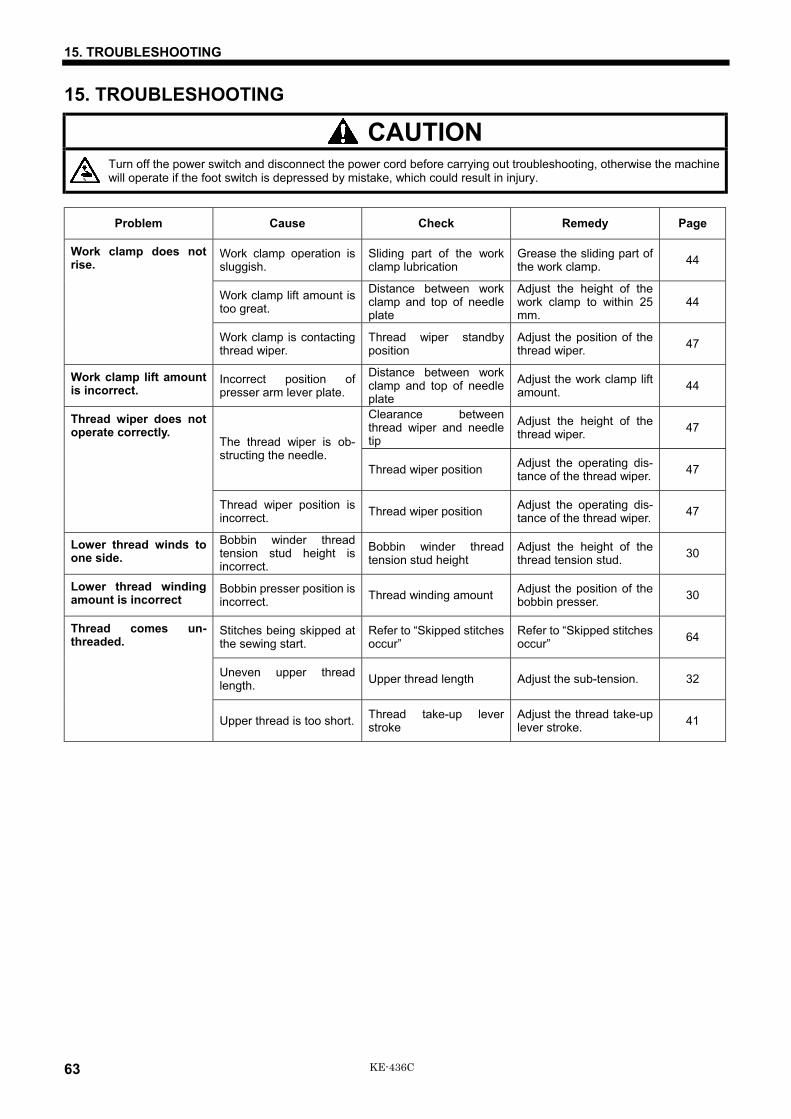
15. TROUBLESHOOTING
63 KE-436C
15. TROUBLESHOOTING
CAUTIONTurn off the power switch and disconnect the power cord before carrying out troubleshooting, otherwise the machinewill operate if the foot switch is depressed by mistake, which could result in injury.
Problem Cause Check Remedy Page
Work clamp operation issluggish.
Sliding part of the workclamp lubrication
Grease the sliding part ofthe work clamp. 44
Work clamp lift amount istoo great.
Distance between workclamp and top of needleplate
Adjust the height of thework clamp to within 25mm.
44
Work clamp does notrise.
Work clamp is contactingthread wiper.
Thread wiper standbyposition
Adjust the position of thethread wiper. 47
Work clamp lift amountis incorrect.
Incorrect position ofpresser arm lever plate.
Distance between workclamp and top of needleplate
Adjust the work clamp liftamount. 44
Clearance betweenthread wiper and needletip
Adjust the height of thethread wiper. 47
The thread wiper is ob-structing the needle.
Thread wiper position Adjust the operating dis-tance of the thread wiper. 47
Thread wiper does notoperate correctly.
Thread wiper position isincorrect. Thread wiper position Adjust the operating dis-
tance of the thread wiper. 47
Lower thread winds toone side.
Bobbin winder threadtension stud height isincorrect.
Bobbin winder threadtension stud height
Adjust the height of thethread tension stud. 30
Lower thread windingamount is incorrect
Bobbin presser position isincorrect. Thread winding amount Adjust the position of the
bobbin presser. 30
Stitches being skipped atthe sewing start.
Refer to “Skipped stitchesoccur”
Refer to “Skipped stitchesoccur” 64
Uneven upper threadlength. Upper thread length Adjust the sub-tension. 32
Thread comes un-threaded.
Upper thread is too short. Thread take-up leverstroke
Adjust the thread take-uplever stroke. 41
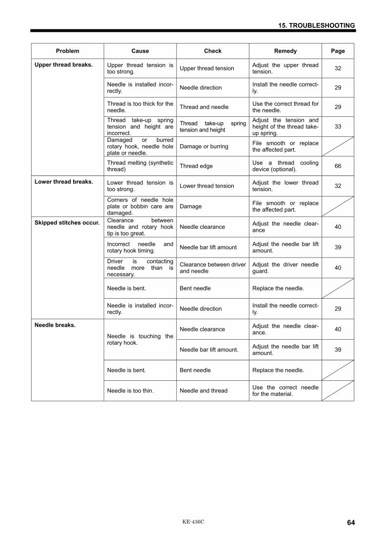
15. TROUBLESHOOTING
64KE-436C
Problem Cause Check Remedy Page
Upper thread tension istoo strong. Upper thread tension Adjust the upper thread
tension. 32
Needle is installed incor-rectly. Needle direction Install the needle correct-
ly. 29
Thread is too thick for theneedle. Thread and needle Use the correct thread for
the needle. 29
Thread take-up springtension and height areincorrect.
Thread take-up springtension and height
Adjust the tension andheight of the thread take-up spring.
33
Damaged or burredrotary hook, needle holeplate or needle.
Damage or burring File smooth or replacethe affected part.
Upper thread breaks.
Thread melting (syntheticthread) Thread edge Use a thread cooling
device (optional). 66
Lower thread tension istoo strong. Lower thread tension Adjust the lower thread
tension. 32Lower thread breaks.
Corners of needle holeplate or bobbin care aredamaged.
Damage File smooth or replacethe affected part.
Clearance betweenneedle and rotary hooktip is too great.
Needle clearance Adjust the needle clear-ance 40
Incorrect needle androtary hook timing. Needle bar lift amount Adjust the needle bar lift
amount. 39
Driver is contactingneedle more than isnecessary.
Clearance between driverand needle
Adjust the driver needleguard. 40
Needle is bent. Bent needle Replace the needle.
Skipped stitches occur.
Needle is installed incor-rectly. Needle direction Install the needle correct-
ly. 29
Needle clearance Adjust the needle clear-ance. 40
Needle is touching therotary hook.
Needle bar lift amount. Adjust the needle bar liftamount. 39
Needle is bent. Bent needle Replace the needle.
Needle breaks.
Needle is too thin. Needle and thread Use the correct needlefor the material.

15. TROUBLESHOOTING
65 KE-436C
Problem Cause Check Remedy Page
Movable knife is bent. Movable knife blade Replace the movableknife. 43
Fixed knife is blunt. Fixed knife blade Sharpen or replace thefixed knife. 43
Shuttle race thread guideposition
Adjust the position of theshuttle race thread guide. 40
Movable knife dose notpick up the thread.
Needle bar lift amount Adjust the needle bar liftamount. 39
The movable knife doesnot pick up the threadbecause of skippedstitches at the sewingend.
Skipped stitches at sew-ing end
Refer to “Skipped stitchesoccur”. 64
Movable knife position isincorrect. Movable knife position Adjust the position of the
movable knife. 42
Upper thread is nottrimmed.
Sub-tension is too weak. Sub-tension Turn the sub-tension nutto adjust the tension. 32
Thread take-up springtension and height areincorrect.
Thread take-up springtension and height
Adjust the tension andheight of the thread take-up spring.
33
Incorrect needle androtary hook timing. Needle bar lift amount Adjust the needle bar lift
amount. 39
Thread jamming.
Shuttle race thread guideis not separating thethreads.
Shuttle race thread guideposition
Adjust the position of theshuttle race thread guide. 40
Shuttle race thread guideis separating the threadsinsufficiently.
Shuttle race thread guideposition
Adjust the position of theshuttle race thread guide. 40
Upper thread is not prop-erly tight. Upper thread tension Adjust the upper thread
tension. 32
Uneven upper threadlength. Upper thread length Adjust the sub-tension. 32
Poor seam finish onreverse side of mate-rial.
Upper thread is too long. Thread take-up leverstroke
Adjust the thread take-uplever stroke. 41
Upper thread tension istoo weak. Upper thread tension Adjust the upper thread
tension. 32
Lower thread tension istoo weak. Lower thread tension Adjust the lower thread
tension. 32
Incorrect thread tight-ness.
Thread take-up springtension and height areincorrect.
Thread take-up springtension and height
Adjust the tension andheight of the thread take-up spring.
33
Head position switch cordconnection
Check if the cord isdisconnected. 9, 10
Switching plate position Adjust the position of theswitching plate. 6
Machine does notoperate when power isturned on and footswitch is depressed. Head position switch
does not work.
Head position switch isbroken.
Replace the head posi-tion switch.
16. OPTIONAL PARTS
66KE-436C
16. OPTIONAL PARTSTwo-step foot switch This is a pedal-type foot switch.
Liquid cooling tank This helps to prevent thread breakages caused by friction whenusing synthetic threads.Fill the tank with silicone oil (100 mm2/s).
Three-pedal foot switch The switch has an independent left work clamp switch (left side),right work clamp switch (center) and start switch (right side).
Work clamp plate, OT Use according to particular sewing needs in order to provide aneven clamping force.
Programmer assy Used to create sewing patterns for the KE-436C. It can also be usedto display error messages.
Thread breakage detector device Available as rotary type or fiber type, stops sewing when a threadbreakage is detected and warns the operator.
Needle cooler device This is a pneumatic-type needle cooler which prevents the threadbreaking due to heat. It is particularly useful when sewing thickermaterials at high sewing speeds.
Air wiper device The thread wiper is driven by a pneumatic cylinder.
2-step thread tension device Allows the upper thread tension to be switched between twosettings at any position desired by using the programmer.
*Refer to the separate Parts Book for details.

INSTRUCTION MANUAL
15-1, Naeshiro-cho, Mizuho-ku, Nagoya 467-8561, Japan. Phone: 81-52-824-2177
Printed in Japan 118-P34S91P34-102
2002.10.B(1)