Embed Size (px)
Citation preview

©DOMETIC - 2004 All rights reserved - Printed in Italy -
No part of this manual may be reproduced, copied or transmitted inany form or by any means without prior written permission fromDOMETIC.
Figures, descriptions, references and technical data contained in thismanual are given as mere example and are not binding.
In pursuing a policy of constant product and safety improvement,DOMETIC reserves the right to effect changes at any time withoutundertaking to give prior notice or to update this manual every time.
Keep this document for future reference.

“The product is warranted in accordance with the enforced Law and regulations implementing the Direc-tive 1999/44/EC.”
The Manufacturer’s warranty does not extend to Product failures, defects or damage arising from and/orattributable to a wrong installation.
The Consumer is entitled to let the Product be installed by an authorised dealer, not bound by Dometic.The warranty extends to failures or defects in the gen-sets which shall become apparent within thewarranty period. The warranty shall cease to have effect if, during the two-year warranty period, the gen-
set is used for more than 1,000 hours or if the recommended service schedule is not completed.

Index
1 General information1.1 Purpose of the manual......................................................... 41.2 Data Plate ........................................................................... 41.3 Safety............................................................................. 51.4 Noise.................................................................................... 51.5 Description of the generator................................................ 61.6 Recommendations for use................................................... 61.7 Fuel................................................................................... 61.8 Operating description.......................................................... 71.9 External control panel........ .................................................. 81.10 Internal control panel........ .................................................. 81.11 Technical data...................................................................... 91.12 Display messages .................................. .......................... 101.13 Routine maintenance........................................................... 111.14 Oil level check...................................................................... 11
2 Installation instructions2.1 Instructions for fixing the generator.................................... 122.2 Instructions for installing the exhaust terminal................... 142.3 Instructions for installing the fuel tank............................... 172.4 Instructions for the electrical connection........................... 18
3 Troubleshooting, maintenance, recycling3.1 Faults, causes, solutions.................................................... 203.2 Checks - nature and service intervals.................................. 213.3 Extraordinary maintenance.................................................. 22
TEC 30 wiring diagram....................................................... 24TEC 30 wiring diagram - 2 TEC in parallel........................ 25TEC 30 spare parts table..................................................... 26
Operation, Maintenance andInstallation manualGenerator
GB
I
D
FHandleiding voor bediening,onderhoud en installatieGenerator
NLManual de instrucciones para el uso, la manutencióny la instalación
Generador E
Livrete de instruções para uso, manutençãoe instalaçãoGerador
PHandbok för drift, underhåll ochinstallationGenerator SKäyttö-, huolto- jaasennusohjeGeneraattori
FINBrukerveiledning og manualtil vedlikehold og installasjonGenerator N
DK
Libretto istruzioni per l’uso, la manutenzione el’installazioneGeneratore
Bedienungs- undWartungsanleitungGenerator
Mise en route, entretien etinstallationGenerateur
Brugervejledning og manualtil vedligeholdelse og installation
Generaattori

TEC 30 4 user’s manual
GB1.1 Purpose of the manual
This manual has been made up by the Manufacturer and is an integratedpart of the generator’s equipment.The information, if respected, will guarantee the correct use of thegenerator.The part of the manual reserved for the users is indicated by the symbol while the part reserved for the experts installing the generator isindicated by the symbol
The following symbols have been used to highlight some parts of thetext:
The operation can be dangerous.
Useful suggestions.
Information on the protection of the environment.
1.2 Data Plate
1 General information
Manufacturer�s data
Conformity marking
Model/Serial numberYear of manufacture
Technical data
Manufactured by WTA v.Virgilio,3 Forlì-Italy
E13
PRODUCT No. MODEL SERIAL
958 500 221 TEC 30 xxxxxxxx
Date 2003Voltage V230Frequency Hz 50Power Factor Cos 1Weight Kg 69.5
Output max W2900Output W2500D.C. 12V A 10

user’s manual TEC 305
GB
• To prevent fire hazards and to keep the generator in an efficientworking condition, do not close the same in a case or an enclosedspace such as an alcove but install it in a well-ventilated area.
• Keep children and animals away from the generator when it isrunning, as it can heat up and cause burns and injuries, bothdirectly and through the systems it is supplying.
• Learn how to turn the generator off quickly and how to use thecontrols. Never leave the generator in the hands of people whoare not trained to use it.
• The generator must only be used with the generator door closed.• Keep flammable substances away from the generator such as
for example: petrol, paints, solvents etc.• Make sure that the hot parts of the generator do not come into
contact with materials that could catch fire.• Fill the generator with fuel in a well-ventilated area with the
generator turned off. Petrol is highly flammable and can explode.• Never overfill the fuel tank. There should not be fuel in the tank
filling throat. Check that the cap is tightly closed.• If you spill any fuel, clean it up thoroughly and wait for the fumes
to evaporate before starting the engine.
The company Dometic is not responsible for any damage caused bygenerator malfunctions.
1.3 Safety
The generator is installed in a closed casing. Therefore, there is nodanger of accidental contacts with moving parts or wires under voltage.The door is fitted with a key lock which shall be kept out of reach bychildren or non-authorised people.
Warning• Check the generator before using it every time. In this way it is
possible to prevent accidents or damage to the motor.
• Exhaust gases contain carbon monoxide, an extremely poisonousgas, which is odourless and colourless. Avoid inhaling exhaustgases. Do not run the engine of the generator in a closed garageor room without very good ventilations.
• Do not touch the generator or the connections with wet hands.• Do not replace fuses or thermal cutouts with others of a higher
amperage.• Any checks carried out on the electric parts should be done by
authorised personnel with the engine turned off.• Install the generator in a stable area. Do not incline the generator
by more than 20° with respect to the vertical plane.• Sudden braking or acceleration, or curves taken abruptly with the
vehicle can cause problems in the pumping system of the generatorand make it stall.
• When storing the generator up for a long period of time, start it atleast once every 30 days and leave it running for at least 15minutes.
• Leave the generator on for a few minutes without charge afteruse before switching it off.
The generator is made to meet the safety regulations indicated in thedeclaration of conformity.
1.4 Noise
The generator has been tested for noise emissions at the qualifiedindependent laboratory DNV Modulo Uno which has issued the EEC-certificate based on EC-DIRECTIVE 2000/14.
GUARANTEED AND MEASURED SOUND POWER LEVEL:
TEC30 ..................................................................... LwA 85
---------------------------------------------------------------------------------SOUND POWER LEVEL measured from 7mt .... dB(A) 60
General information 1

TEC 30 6 user’s manual
GB1.5 Description of the generator
WarningThe TEC 30 generator has been designed and produced to be usedonly on caravans, motor homes and commercial vehicles.Therefore it has not been designed to be used on other types of vehiclesor on any kind of watercraft. The company Dometic, as it is impossibleto envisage every possible use and type of installation, declines anyresponsibility for every type of use and installation which is not explicitlymentioned.
The generator has been designed to produce alternating current at230V and 50 Hz, capable of supplying power to various systems.Therefore it is fitted with an inverter, so that it can supply systems thatare very sensitive to the quality of the energy supplied, such as personalcomputers for example.The generator is installed in a sheet metal steel casing which is insulatedand soundproofed with special soundproofing materials.
1.6 Recommandations for use
To use the generator in the best way it is a good idea to pay attention toeven small overloads, which if prolonged, will cause the protectivethermal cutouts to trip.When running in it is important not to put the new engine under a loadthat exceeds 70 % of the nominal load, at least for the first 50 workinghours; then we recommend a normal use of the generator with a loadequal to roughly 3/4 of the maximum declared continuous load, this inorder to prolong the life of the generator and maximize efficiency.When the generator is hot we recommend starting by pushing the startbutton briefly, while when the generator is cold hold the start buttondown for longer.
1 General information
1.7 Fuel
All diesel oils which satisfy the following specifications are suitable:
EN 590 orDIN 51601 - DK orBS 2869 A1 / A2 orASTM D975 -1D / 2D
At temperatures below 0°C, winter-grade fuel should be used or paraffinadded to the fuel well in advance.
tneibmatsewoLnehwerutarepmet
)C°(ni,gnitrats
:roftnetnocniffaraP
remmuSleuf
retniWleuf
01-a0 %02 -
51-a01- %03 -
02-a51- %05 %02
N.B.To facilitate the start up of the generator with low temperatures, thepreheating glow plug available (accessory AG165) may be installed.

user’s manual TEC 307
GB
General information 1
INVERTERCONTROL CARD
(C)
INTERNALCONTROL
PANEL(D)
ALTERNATORUNIT
(B)
ENGINE (A)
EXTERNALCONTROL
PANEL(F)
TERMINALBOARD (E)
1.8 Operation description
The main elements of the TEC 30 generator are: an engine (a), a permanent magnet alternator (b), an inverter (c), an internal control panel (d), aterminal board (e) and an external control panel (f).When the engine runs it drives the alternator to which it is solidly connected, which in turn generates alternating current that supplies the inverter.The inverter “converts” the voltage supplied into a higher quality, perfectly stable voltage of 230 V and 50Hz supply.The terminals, the socket where the extension of the external control panel is connected and the safety switch are located on the internal controlpanel.
The external control panel is equipped with:
- buttons to start and stop the generator- a back lit LCD screen showing the main electrical
properties, an indicator shows that the generator isworking properly and an hour counter is also displayed.In the case of problem the alarm messages are dis-played on this screen.
- LED indicators indicate low levels of petrol and oil.

TEC 30 8 user’s manual
GB1.9 External control panel
1 General information
Operation description
MAIN SWITCH: turns the panel on/stops the generatorSTART BUTTON : starts the generatorPETROL INDICATOR : indicates that you are using the fuel reserveOIL INDICATOR : indicates a low oil level and the engine automatically stopsEMERGENCY STOP SWITCH: stops the generator immediately in an emergencyCUT OUT SWITCH: continuous current thermal cut out protection
1.10 Internal control panel
EMERGENCYSTOP SWITCH
CUT OUT SWITCH
MAIN SWITCH
STARTBUTTON PETROL
INDICATOR
OILINDICATOR
DISPLAY
VOLTAGEDELIVERED
BATTERY’S DCVOLTAGE
POWER DELIVEREDWORKING HOURS
GENERATORSTATUS

user’s manual TEC 309
GB
NOITPIRCSED NOITPIRCSED NOITPIRCSED NOITPIRCSED NOITPIRCSED ERUSAEMFOTINU ERUSAEMFOTINU ERUSAEMFOTINU ERUSAEMFOTINU ERUSAEMFOTINU EULAV EULAV EULAV EULAV EULAV
DEILPPUSEGATLOV DEILPPUSEGATLOV DEILPPUSEGATLOV DEILPPUSEGATLOV DEILPPUSEGATLOV VVVVV %01±032 %01±032 %01±032 %01±032 %01±032
REWOPSUOUNITNOCXAM REWOPSUOUNITNOCXAM REWOPSUOUNITNOCXAM REWOPSUOUNITNOCXAM REWOPSUOUNITNOCXAM WWWWW %5±0052 %5±0052 %5±0052 %5±0052 %5±0052
YCNEUQERF YCNEUQERF YCNEUQERF YCNEUQERF YCNEUQERF zHzHzHzHzH %1±05 %1±05 %1±05 %1±05 %1±05
REWOPTNERRUCTCERID REWOPTNERRUCTCERID REWOPTNERRUCTCERID REWOPTNERRUCTCERID REWOPTNERRUCTCERID A/V A/V A/V A/V A/V 01/21 01/21 01/21 01/21 01/21
DHT DHT DHT DHT DHT %%%%% 11111
NOITPMUSNOC NOITPMUSNOC NOITPMUSNOC NOITPMUSNOC NOITPMUSNOC h/PH/g h/PH/g h/PH/g h/PH/g h/PH/g 012/002 012/002 012/002 012/002 012/002
THGIEW THGIEW THGIEW THGIEW THGIEW gkgkgkgkgk 5.96 5.96 5.96 5.96 5.96
1.11 Technical data
General information 1
462
542
506
40297
406
484
TEC 30 10 user’s manual
GB1.12 Table describing the alarm messages appearing on the display
1 General information
EGASSEMDEYALPSID EGASSEMDEYALPSID EGASSEMDEYALPSID EGASSEMDEYALPSID EGASSEMDEYALPSID NOITPIRCSED NOITPIRCSED NOITPIRCSED NOITPIRCSED NOITPIRCSEDROTARENEG ROTARENEG ROTARENEG ROTARENEG ROTARENEGRUOIVAHEB
SNOITCA SNOITCA SNOITCA SNOITCA SNOITCA
YRETTABWOL eulavmuminimehtwolebsiegatlovyrettabehttahtsetacidnI.rotarenegehttratsotyrassecen
tonseodrotarenegehT.trats
ehtfoycneiciffeehtkcehCehtgnitratserofebyrettab
.rotareneg
EGNAHCLIOehtforetnuocruohehtemityrevesraeppaegassemsihTehtegnahcottes-erplavretniecivresehtsehcaerenihcam
.lioenigne
otseunitnocrotarenegehT.nur
)22.pees(lioehtegnahCehtgnitratsererofeb
ehtgnidlohybrotareneg.regnolrofnwodnottubtrats
LEUFON .evreserleufehtgnisuerauoytahtsetacidnIotseunitnocrotarenegehT
.nur.leufeR
TRELALIO .knatlioehtnilioeromonsierehT .spotsrotarenegehT .)11egapees(pulliF
!TRELAROTARENEGehtnehwecnatsnirofdeyalpsidsiti;egassemmralalareneGdnaevitcefedsi)rotompets(elttorhtrotterubracehtfognirkcehc
deepsrotomehtkcehctonnaceludom011Meht.spotsrotarenegehT
noelbatgnitoohselbuorTeeSmelborpehtfI.02egapehtotsserdda,stsisrep.ertnececivrestseraen
!DAOLREVO .smetsysdeilppusehtfodaolrevotuptuonasetacidnI
dnaspotsretrevniehTregnolonsiegatlov
enigneehttub,deilppustcerrocarofnurotseunitnoc
.straplanretniehtfognilooc
,daoldetcennocehtecudeRloocotsetunimwefatiaw
ehtpotS.rotarenegehtnwodniamehtgnisserpybenigne
tratsernehT.nottubhctiws.rotarenegeht
TIUCRICTROHS .smetsysdeilppusehtfotrohstuptuonasetacidnI
dnaspotsretrevniehTregnolonsiegatlov
enigneehttub,deilppustcerrocarofnurotseunitnoc
.straplanretniehtfognilooc
detcennocehtllakcehCsetunimwefatiaw,smetsys.rotarenegehtnwodloocotgnisserpybenigneehtpotS
.nottubhctiwsniameht
ERUTAREPMETREVO .daolrevolamrehtafotneveehtnideyalpsidsiegassemsihT
dnaspotsretrevniehTregnolonsiegatlovenigneehT.deilppus
tcerrocarofnurotseunitnoc,straplanretniehtfogniloocegassemehtdnaspotsneht
TRATSER“sideyalpsid.”?NEG
,nwodloocrotarenegehtteLdnasetunimwefatiaw
.tinuehttratser
ENIGNEREWOPWOL .retrevniehtotdeilppusegatlovehtfonoitcuderaslangiS .spotsrotarenegehTdaoldetcennocehtecudeR
.rotarenegehttratserdna
?NEGTRATSER .rotarenegehtfopotsynaretfasraeppaegassemsihT .spotsrotarenegehTehttratserdnaffonruT
.rotareneg
LACNEGsetacidnidnapu-tratsrotarenegehttasraeppaegassemsihTrotarenegehT.pu-tratsynagnidecerpesahpnoitarbilaceht
.teytnerrucecudorptonseod
tubnurrotarenegehT.deilppustonsiegatlov
.sdnoceswefatiaW
TIAWNEG .rehtoehtdnatpmettatratsenoneewtebdeyalpsidegasseM .nurtonrotarenegehTseogegassemehtlitnutiaW
wenagnitpmettaerofebffo.trats
NONEG .gninnursirotarenegehttahtsetacidnI
FFONEG nurtonrotarenegehttahtsetacidnI .nurtonrotarenegehTuoyfinottubtratsehthsuP
rotarenegehttratserottnaw

user’s manual TEC 3011
GB1.13 Routine maintenance
To perform these checks you should open the door of the generatortaking the following precautions:
The generator must not be running and all of the parts must be cold.
Set the safety switch on the internal control panel to “O” (OFF).Disconnect the positive pole (+) of the vehicle�s battery
IMPORTANT: Use only genuine spare parts. The generator mayget damaged if other than genuine parts having a different qualitystandard are used.
IMPORTANT:Remember to reconnect the positive pole (+) of the vehicle�s batteryand set the switch back to “I” (ON) once you have finished the checks.
1.14 Checking the oil level
Remove the oil filler and clean the dipstick with a cloth.Refit by screwing the dipstick.Remove the dipstick and check that the oil level is between the two(min. and max.) marks.Add oil if necessary through the filler. Use only the oil recommended bythe manufacturer!
Refit the plug.
IMPORTANT:Perform all of the checks making sure the generator is in a horizontalposition.
General information 1

TEC 30 12 user’s manual
GB2.1 Instructions for fixing the generator
WarningMake sure there is enough space around the casing of the generator for cooling, leaving at least 70 mm of free space between the casing and thesurrounding walls or parts. If the air intake of the generator remains behind a wheel of the vehicle, make sure that in the case of rain the wheel willnot spray water onto or into the generator taking preventing measures if necessary (ex. antispray guards).There are two different installation solutions to mount your generator unit: outdoor hanging installation (A TYPE) or installation in a separatecompartment (B TYPE).An “A TYPE” installation may be preferable for the following: smaller overall dimensions, quick installation, ease of access for ordinary and ex-traordinary maintenance. A “B TYPE” installation instead allows for further soundproofing of the generator unit compartment.
For “A TYPE” installation (hanging installation) the generator unit is fitted with item AG129 (available upon request) consisting of hanging brackets(ref. no. AG129/ST) and a bent exhaust pipe (ref. no. 4205), as shown in the figure. Dismount the hanging brackets and reassemble them upsidedown (see figure).Use the pre-printed cardboard sheet supplied with the package as a shape template to secure AG129/ST brackets onto the supporting wall.Secure the generator unit onto the hanging brackets with the vibration dampers supplied.Mount the bent exhaust pipe and secure the flexible connecting pipe with clamps to the additional muffler
2 Installation instructions
A TypeAG129
AG129/ST
shape template
INS
TAL
LA
TIO
N T
YP
E B
(insid
e a
co
mp
artm
en
t)
fixin
gh
ole
sfix
ing
ho
les
fixin
gh
ole
s
AG129
Dra
in H
ole
Dra
inH
ole
SEE USER'S M
AN
UA
LREM
OVE TH
IS CA
RTON
AFTER IN
STALLATIO
N
INS
TAL
LA
TIO
N T
YP
E A
(ha
ng
up
un
de
rne
at)
FRONT
TOP
INS
TA
LL
AT
ION
TY
PE
B(in
sid
e a
co
mp
artm
en
t)
fixin
gh
ole
sfix
ing
ho
les
fixin
gh
ole
s AG129
Dra
in H
ole
Dra
inH
ole
SEE USER
'S MA
NU
AL
INS
TA
LL
AT
ION
TY
PE
A(h
an
g u
p u
nd
ern
ea
t)
FRONT
TOP
INSTALLATION TYPE B(inside a compartment)
fixingholes fixing
holes
AG129
Drain Hole
DrainHole
SEE USER'S MANUAL
INSTALLATION TYPE A(hang up underneat)
FRONT
TOP
4205

user’s manual TEC 3013
GB
~ 3 x R MIN = 240
AG163
R80 MIN
B TypeAG164
4209
3013
In “B TYPE” installation the generator unit is fitted with item AG164 – available upon request – consisting of a gasket (ref. no. 3013) and a straightextended exhaust pipe (ref. no. 4209) as shown in the figure below.An airtight separate compartment must be prepared inside the vehicle. This compartment may also be soundproofed.Use the pre-printed card-board sheet supplied with the package as a shape template to pierce the air vent openings.Secure the self-adhesive gasket. The gasket is needed to convoy hot exhaust gases out of the compartment.Remove the screws from the generator unit bottom and insert the two flange nuts to secure the generator unit bottom in the inner position (asshown in the figure). This will allow to loosen the unit bottom for ease of ordinary maintenance of the generator unit.Mount the straight exhaust pipe and secure the flexible connecting pipe with clamps to the additional muffler.Ensure that the flexible connection pipe is not overbent once secured. The minimum bending radius should be the same as recommended inthe figure.
Warning: to allow for proper cooling of the generator unit, maintain a minimum 70mm between the generator unit and the surroundingwalls. Pierce an air vent opening on top of the compartment facing outward door of minimum 240 cm2.. Ensure not to obstruct air intake andexhaust ports or to let exhaust gases flow in.
shape template
INS
TAL
LA
TIO
N T
YP
E B
(insid
e a
co
mp
artm
en
t)
fixin
gh
ole
sfix
ing
ho
les
fixin
gh
ole
sAG129
Dra
in H
ole
Dra
inH
ole
SEE USER'S M
AN
UA
LREM
OVE TH
IS CA
RTON
AFTER IN
STALLATIO
N
INS
TAL
LA
TIO
N T
YP
E A
(ha
ng
up
un
de
rne
at)
FRONT
TOP
INS
TA
LL
AT
ION
TY
PE
B(in
sid
e a
co
mp
artm
en
t)
fixin
gh
ole
sfix
ing
ho
les
fixin
gh
ole
s AG129
Dra
in H
ole
Dra
inH
ole
SEE USER
'S MA
NU
AL
INS
TA
LL
AT
ION
TY
PE
A(h
an
g u
p u
nd
ern
ea
t)
FRONT
TOP
INSTALLATION TYPE B(inside a compartment)
fixingholes fixing
holes
AG129
Drain Hole
DrainHole
SEE USER'S MANUAL
INSTALLATION TYPE A(hang up underneat)
FRONT
TOP
Installation instructions 2

TEC 30 14 user’s manual
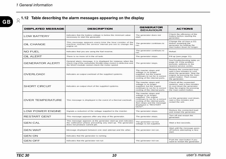
GB 2.2 Instructions for installing the exhaust system
We recommend positioning the elbow of the exhaust pipe in line with the length of the casing (as shown in the figure) so more vibrations can beabsorbed.Use the exhaust extension (AG125) to extend the position of the muffler. Fix the exhaust extension to the vehicle using flexible elements to reducevibrations (extension fixing is avalaible as accessory upon request - Ref. AG163).The accessory AG134 is available upon request to improve the soundproof.
WARNINGDo not make any sharp bends in the hose which could obstruct the exhaust gas. EXTENSION FIXING
AG163 (OPTIONAL)
MUFFLEREXHAUST
EXTENSIONAG125
TEC 30
AG134 (OPTIONAL)
2 Installation instructions

user’s manual TEC 3015
GB Instructions for installing the exhaust system
AG163
Installation instructions 2
TEC 30 16 user’s manual
GB Instructions for installing the exhaust system
AG163
AG163
AG163
2 Installation instructions

user’s manual TEC 3017
GBGenerator TEC30 is equipped as standard with an electric pump for pumping fuel. The following should be done.
The fuel tank should be installed with the tank basis at a maximum depth of 1.5 meters below the lower edge of thegenerator box. For safety reasons ensure not to mount the generator box top edge higher than the tank top edge.
TANK MAXIMUM LOWER EDGE
TANK MAXIMUM TOP EDGE
Instructions for the installation of the tank
Max 1.5m
Installation instructions 2
3m

TEC 30 18 user’s manual
GB2.3 Instructions for the electrical connection
The Dometic generator is a source of alternate 230V 50Hz tension,able to cope with various power needs.
WarningYou will have to install a relay or commutator in the vehicle�s electricalsystem (ex. the accessory AG 102) in order to prevent damaging thegenerator when the external mains is connected; in this case we suggestconnecting the generator so that it has priority over the external mainsnetwork.
Electric wiring must be effected in conformity with the existing lawsand regulations in force in the user’s country.For correct installation performed by the final user, use preventive tech-nical assistance by your seller or by a skilled technician.
For the 230 V use a cable of a standard cross-section as shown in thetable; insert it in the casing through the cable guide and connect it tothe terminals. Connect the earth wire.
Electrical connection of the battery charger
Use a cable finding the correct section in the chart on the right.Connect the cable to the connecting terminal and to the positive poleof the battery to be charged.Should the battery be others than that used to start the generator, thenconnect the negative pole of this battery to the proper mass point ofthe generator (see picture on page 19).NB:The negative pole of the battery should be grounded with thevehicle’s frame.
2 Installation instructions
mmnoitces-ssorC mmnoitces-ssorC mmnoitces-ssorC mmnoitces-ssorC mmnoitces-ssorC 22222
V032 V032 V032 V032 V032)selbacrewop(
mmnoitces-ssorC mmnoitces-ssorC mmnoitces-ssorC mmnoitces-ssorC mmnoitces-ssorC 22222
V21 V21 V21 V21 V21)regrahcyrettab(
mmnoitces-ssorC mmnoitces-ssorC mmnoitces-ssorC mmnoitces-ssorC mmnoitces-ssorC 22222
m6otpuhtgneL m6otpuhtgneL m6otpuhtgneL m6otpuhtgneL m6otpuhtgneL)noitcennocyrettab(
mmnoitces-ssorC mmnoitces-ssorC mmnoitces-ssorC mmnoitces-ssorC mmnoitces-ssorC 22222
m6>htgneL m6>htgneL m6>htgneL m6>htgneL m6>htgneL)noitcennocyrettab(
5.2 5.2 5.2 5.2 5.2 5.2 5.2 5.2 5.2 5.2 6161616161 5252525252
External controlpanel socket
Emergency stop switch
Socket fortank floatwire
12 V plugfor batterycharger
Earth wire230 Vplug
Cut out switch

user’s manual TEC 3019
GBBattery connection
To start the generator, connect it to the positive pole of the vehicle�sbattery with a sheathed cable of a suitable cross-section as shown inthe table. The ground cable must have the same cross-section and beconnected or as shown in the figure to the side or from the inserts tothe frame of the vehicle. Make sure that the contact is good. If necessaryremove paint or rust from the surface of the frame and protect theconnection with grease.To protect the DC wiring use a 100Amp fuse closed to the plus pole ofthe battery.
External control panel connection
Choose the desired position inside the vehicle, use the extension lead(supplied) to connect the external control panel to the internal controlpanel of the generator.
Installation instructions 2
(+) Pluspole
(-) negativepole
Inserts

TEC 30 20 user’s manual
GB
SO
LUT
ION
The
emer
genc
yst
opsw
itch
isno
tto
ON
The
star
ter
isno
tpow
ered
up
The
elec
tric
alca
bles
are
brok
en
The
gene
rato
rea
rth
wire
(or
fuse
)is
brok
en
No
fuel
Che
ckth
elo
adsu
pplie
d
No
fuel
rece
ived
from
inje
ctor
s
The
air
filte
ris
dirt
y
The
Air
inta
kes
are
obst
ruct
ed
Inve
rter
isda
mag
ed
Load
over
2.5
kW
Low
batte
rych
arge
The
star
ter
shaf
tis
dirt
y
Ele
ctric
pum
pun
fed/
outo
ford
er
Too
muc
hoi
lin
the
engi
ne
CAUSE
By ope ra ting the m a in sw itch, thepa ne l does not sw itch on
By pushing the sta rt button, thege ne ra tor doe s not sta rt (the sta rtingm otor doe s not run)
The sta rting m otor runs but thege ne ra tor doe s not sta rt
The ge ne ra tor te nds to sta ll
The ge ne ra tor runs but it doe s notproduce current
The ge ne ra tor sta rts, the n stops anddispla y “ge nera tor a lle rt” m e ssage
The produced current oscilla tes
3.1 Faults, causes and solutions
3 Troubleshooting, maintenance, recycling
Operations to be carriedout by the user
Operations to be carried outby qualified technicians

user’s manual TEC 3021
GB3.2 Check list and time intervals
Troubleshooting, maintenance, recycling 3
trahcecnanetniaM trahcecnanetniaM trahcecnanetniaM trahcecnanetniaM trahcecnanetniaM deriuqerkrowecnanetniaM deriuqerkrowecnanetniaM deriuqerkrowecnanetniaM deriuqerkrowecnanetniaM deriuqerkrowecnanetniaM
51-8 51-8 51-8 51-8 51-8 ro,sruohgnitarepo51-8yrevEputratsyliadhcaeerofeb
levelliokcehC.enozekatniriagniloocdnanoitsubmockcehC
052 052 052 052 052
sruohgnitarepo052yrevE (lioenigneegnahC raeyaecnotsaeltaesacynanI ).secnaraelcevlavtsujdadnakcehC
.aerariagniloocnaelC.snoitcennocwercskcehC
.tsuahxeroftresnihsemnaelC
005 005 005 005 005 sruohgnitarepo005yrevE .tnemeleretlifleufegnahC.ecnanetniamrenaelcriaepyt-yrD
0001 0001 0001 0001 0001 0001yrevE sruohgnitarepo retliflioehtnaelC
raeyaecnO tniopgnixiffoorp-noitarbiV

TEC 30 22 user’s manual
GB
ImportantOld oil moust not be disposed of in the environment, but left to astation specialised in the disposal and/or recycling of the same,respecting the laws in the country where the operations are carriedout.
Use oil recommended for 4-stroke Diesel engines of these types:CCMC-D4-D5-PD2 or API-CD-CE-CF-CG or SHPD (this indication ison the oil can).SAE 10W-30 oil is recommended for general use at all temperatures.If you use monograde oil, choose the appropriate viscosity on thebasis of the average temperature of the place where the generator isinstalled.To drain the old oil easier you should run the generator for roughly 3/5minutes, in this way the oil is more fluid and will drain better throughthe drain tube when you remove the drain plug. Refill the generatorwith oil of the recommended type, through the oil filler.The quantity of oil is:
0.9 Litres
3.3 Extraordinary maintenance
For some maintenance operations there is the possibility of pulling thegenerator out by sliding the entire bottom of the generator on the guidesfixed to the sidewalls of the casing. To set the generator basis freeloosen the harness and unscrew the 4 fastening screws. The generatorunit will be extractable by ¾ of its depth. To come to a completeextraction put the generator basis on firm ground to protect it againstpossible falls and unscrew the 2 limit stop screws. Alternatively tightenthe generator basis inserting screws in inner position.
Changing the oilWarning
• Hot oil can burn your skin!• Check the oil level with the engine turned off.
3 Troubleshooting, maintenance, recycling
Fixingscrew
Oil drain plug
Limit stop screw
122
104
86
68
50
32
14
-4
-22
-40
50
40
30
20
10
0
-10
-20
-30
-40
˚F ˚C
5W/3
0
5W/4
0
10W 10
W/3
0
10W
/40
15W
/40
20W
/20 30
40
OIL : SAE
Internal position
user’s manual TEC 3023
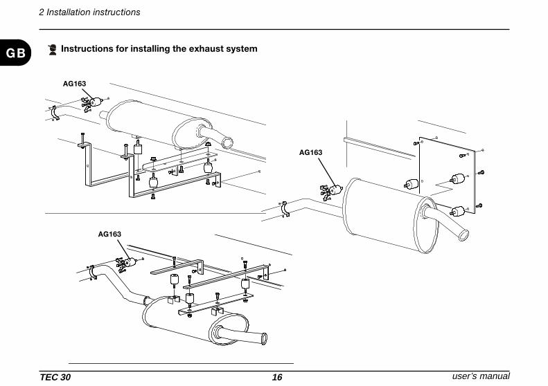
GBAir filter maintenance
WarningDo not use diesel or solvents with a low evaporation point to clean theair filter element as it could catch fire or explode.
ImportantIf the air filter is dirty this reduces the flow of air to the engine. Therefore,to prevent malfunctions we recommend checking the state of thefilter periodically, and more often if you are using the TEC 30 inparticularly dusty areas.Never use the engine without the air filter. The engine would wearquickly.
Operations:Remove the air cleaner cover.Unscrew and remove knurled nut and take off air cleaner element.Clean the filter compartment and the cover.Dirt and other foreign bodies must not be allowed to enter the engine'sair inlet points.The filter cartridge should either be renewed or, depending upon thedegree of contamination, cleaned, or checked, as follows:
Troubleshooting, maintenance, recycling 3
Cleaning the filter cartridgeDry contaminationUse compressed air to blow through the filter cartridge from the inside outwards, until no further dirt emerges.Important ! The pressure must not exceed 5 bar.
Moist or oily contaminationRenew the filter cartridge.
Checking the filter cartridgeCheck filter cartridge's gasket surface for damage, Check the filter cartridge for cracks or any other type of damage to the paper filter byholding it inclined towards the light or by shining a light source through it.Important ! The slightest damage to the paper filter rules out it being used any longer. Re-assemble the filter cartridge in the reverse order ofwork.

TEC 30 24 user’s manual
GB
TEC 30 WIRING DIAGRAM
MOTORE HATZ
DIESEL
2019
17
1312
8
7
29
28
27
26
14
9
11
+
2 3
98
654
1110 12
1
7
N OW
KN
58 7 6 2 14 3
2312
T
11 10 9
E
GR
E
BLU
YE
LB
LA
BR
O
RE
D
VIO
LP
IN
GR
EW
HI ET EEK Y L CW
22
GR
EY
YELLOW
YELLOW
RE
D
BLA
CK
RED
BLACK
BLACK
OR
AN
GE
WH
ITE
WH
ITE
+-
+
10 M
P
PUMP
+ + + + +
-
BR
OW
N
OR
AN
GE
PIN
K
+
PINKORANGE
125 3464 3 2 16 5
R3R3 R2 R2 R1R1
RG
YE
YE
LLO
WY
ELL
OW
821
4
1 432
1
BLU
6
25EY
GR
1 2 1 432 5
2
BLU
5
87
65
13
24
65
87
13
24
CYAN
CYAN
CYAN
RED
WHITE
WHITE
6
99
15
BLACKBLACK
RED
B
230
230
12
161
18
ER
DNL L O
9
PI
812 11
B B
10
VI
KAC
KU
E LET
L
4567
BA
CK
3
BLU
EN
EN
WK WO
GR
BRBLA
YE
L EOC L
E YR
E
WH
IG
RDT E
TV
IOLE
7810 9 123456
PIN
K
2
1
3
24
2
DESCRIPTION
1 THREE-PHASE WINDING
2 AUXILIARY WINDING
3 AUXILIARY WINDING
4 INVERTER MODULE
5 9-PIN CONNECTOR
6 12V REGULATOR
7 0/1 EMERGENCY STOP SWITCH
8 PRESSURE CONTROL DEVICE
9 START RELAY
10 STARTING MOTOR
11 9-PIN CONNECTOR
12 HATZ 6-PIN CONNECTOR M
13 HATZ 6-PIN CONNECTOR F
14 INTERNAL CONTROL PANEL
15 THERMAL SWITCH
16 INTERFACE MODULE
17 ELECTROSTOP
18 12-PIN CONNECTOR
19 PREHEATING GLOW PLUG
20 TEMPERATURE SENSOR
21 2-PIN CONNECTOR
22 VEHICLE CONTROL PANEL
23 12-PIN CONNECTOR
24 AUXILIARY WINDING
25 CYLINDRICAL CONNECTOR
26 PREHEATING RELAY
27 PUMP RELAY
28 MOTOR START RELAY
29 4-PIN CONNECTOR
user’s manual TEC 3025
GB
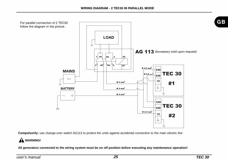
WIRING DIAGRAM - 2 TEC30 IN PARALLEL MODE
#2
TEC 30
TEC 30
#1
230
AG 1133R3 A2
R4 4 A1
230
230
230
12
R11
2 R2
12
Ø 2.5 mm2
Ø 4 mm2
Ø 4 mm2
Ø 4 mm2
Ø 2.5 mm2
Ø 2.5 mm2
Compulsorily: use change-over switch AG113 to protect the units against accidental connection to the main electric line
WARNING!
All generators connected to the wiring system must be on off position before executing any maintenance operation!
LOAD
MAINS
BATTERY
For parallel connection of 2 TEC30follow the diagram in the picture .
(Accessory sold upon request)

TEC 30 26 user’s manual
GB
TEC 30 SPARE PARTS TABLE
3457
59
60
12
15
14
13
12
11
10
89
8
1
40
38
21
24
17 16
5
22 6 26
27
31
30 29 28
4
3
2
7
3739
51
56
53
54
55
52
46 49
44
19
78
42
36
2379
43
3320
35
41
45
A
A
4748
65
63
64
62 66
67
75
76
61
77
68
69 70 71 69
72
74
73
5857
AG129 AG164 OPTIONAL OPTIONAL
AG163
AG165
OPTIONAL
25
18
50
32
accessory accessory

user’s manual TEC 3027
GB
TEC 30 SPARE PARTS TABLE
1 1B20V ENGINE
2 STATOR
3 ROTOR
4 INVERTER
5 12V REGULATOR
6 INTERNAL CONTROL PANEL CARD
7 STATOR CENTRING PLATE
8 MEDIUM SPACER
9 LOW SPACER
10 HIGH SPACER
11 FAN FIXING PLATE
12 FAN
13 SPACER
14 COVER ENGINE
15 FAN FIXING PLATE
16 COVER
17 LIMIT STOP LOCK
18 INVERTER SUPPORT PLATE
19 CASING DOOR
20 BUSH
21 CABLE GUIDE
22 THERMAL CUTOUT
23 CASING BASE
24 SPACER
25 INVERTER SUPPORT PLATE
26 RELAY
27 SUPPORT PLATE INT. CONTROL PANEL
28 CABLE GUIDE
29 TERMINAL
30 TERMINAL
31 BIPOLAR SWITCH
32 CONTROL PANEL
33 VIBRATION DAMPERS
34 EXHAUST EXTENSION
35 GENERATOR CASING
36 BUSH
37 DRILLED SCREW
38 WASHER
39 OIL PIPE
40 EXHAUST PIPE
41 VIBRATION DAMPERS
42 BUSH
43 WIRE WOOL
44 HOSE CLAMP
45 FUEL PUMP
46 CONTROL PANEL EXTENSION
47 WASHER
48 NUT
49 WIRING
50 CABLE GUIDE
51 EXHAUST PIPE GASKET
52 COMPLETE CONTROL PANEL
53 CONTROL PANEL CARD
54 CONTROL PANEL BOX
55 CONTROL PANEL STICKER
56 INT. CONTROL PANEL STICKER
5 7 H O S E C L A M P
5 8 S IL E N C E R
5 9 V IB R A TIO N D A M P E R
6 0 S IL E N C E R F IXIN G B R A C K E T
6 1 C O M P L E TE S IL E N C E R
6 2 A TY P E IN S TA L L A TIO N K IT
6 3 S P A C E R
6 4 B R A C K E T
6 5 C U R V E D E XH A U S T P IP E
6 6 B TY P E IN S TA L L A TIO N K IT
6 7 E XH A U S T P IP E E XTE N S IO N
6 8 G A S K E T
6 9 H O S E C L A M P
7 0 V IB R A TIO N D A M P E R
7 1 S IL E N C E R
7 2 E XTE N S IO N F IXIN G
7 3 H O S E C L A M P
7 4 V IB R A TIO N D A M P E R
7 5 P R E H E A TIN G G L O W P L U G K IT
7 6 R E A L Y
7 7 P R E H E A TIN G G L O W P L U G
7 8 L O C K
7 9 G A S K E T
![Maskindiagnostik Driftsäkerhet och Underhåll [Kompatibilitetsläge] · 2011-09-26 · 2011-09-26 2 Avhjälpande underhåll, AU, Immediate maintenance – Underhåll som utförs](https://img.pdfslide.net/doc/110x75/5e47636de7d3f171954ddb92/maskindiagnostik-driftskerhet-och-underhll-kompatibilitetslge-2011-09-26.jpg)