Embed Size (px)
Citation preview

USSC 1
King/Ashley Pellet Stove
Please read this entire manual before installation and use of this appliance. Failure to follow these instructions could result in property damage, bodily injury, or even death.
Contact your local building or fire officials about restrictions and installation inspection requirements in your area.
Save these instructions.
Owner’s Manual
UNITED STATES STOVE COMPANY • 227 INDUSTRIAL PARK ROAD • SOUTH PITTSBURG, TENNESSEE 37380 • WWW.USSTOVE.COM
FOR TECHNICAL ASSISTANCE: PHONE: (800) 750-2723 FAX: (423) 837-2109
Part No.: 851641
UNITED STATES STOVE COMPANY“Keeping North America Warm Since 1869”
models 5500/5500M/5500XL
CSSUCOMPANY
UNITED STATES STOVE
5500M
5500XL
5500
E
2 USSC
TABLE OF CONTENTS ..............................................................................................2SAFETy PrECAuTiONS ...........................................................................................3SPECiFiCATiONS .......................................................................................................4 HeatingSpecifications .....................................................................................4 Dimensions ......................................................................................................4 ElectricalSpecifications ...................................................................................4 FuelConsiderations .........................................................................................4 SafetyandEPACompliance ............................................................................4iNSTALLATiON ..........................................................................................................5 InstallationOptions ..........................................................................................5 FloorProtection ...............................................................................................5 Clearances ......................................................................................................6 VentingRequirements .....................................................................................7 MaximumVentingDistance .............................................................................7 PelletVentType ...............................................................................................7 PelletVentInstallation .....................................................................................7 PelletVentTermination ....................................................................................7 VentTerminationClearances ...........................................................................8 ThroughtheWallInstallation ...........................................................................9 ThroughtheRoof/CeilingInstallation...............................................................9 OutsideAirSupply .........................................................................................10 SpecialMobileHomeRequirements .............................................................10uNdErSTANdiNg yOur STOvE ........................................................................... 11CONTrOL PANEL OvErviEw ................................................................................12OPErATiON ........................................................................................................13-15 UnitPreparation .............................................................................................13 PerformingInitialTest ....................................................................................13 Performinga“DryRun” ..................................................................................13 Start-UpProcedure ........................................................................................14 ShutDownProcedure ....................................................................................14 DailyOperation ..............................................................................................15 SafetyandConvenienceFeatures ................................................................15MAiNTENANCE ...................................................................................................15-16 ExhaustSystem .............................................................................................15 InteriorChambers ..........................................................................................16 AshDisposal ..................................................................................................16 CheckandCleantheHopper ........................................................................16 MainDoorGaskets ........................................................................................16 BlowerMotors ................................................................................................16 PaintedSurfaces ...........................................................................................16 Glass ..............................................................................................................16 Fall Start-Up ...................................................................................................16 SpringShutDown ..........................................................................................16 YearlyServicing .............................................................................................16TrOuBLE ShOOTiNg .............................................................................................17ErrOr COdES & diSPLAy iNdiCATOrS .............................................................18rEPAir PArTS diAgrAM/LiST ........................................................................19-21wiriNg diAgrAM ...................................................................................................22
Table of Contents

USSC 3
Safety PrecautionsIMPORTANT:Readthisentiremanualbeforeinstallingand operating this product. Failure to do somayresultinpropertydamage,bodilyinjury,orevendeath.Properinstallationofthisstoveiscrucialforsafeandefficientoperation.
Install vent at clearances specified by the ventmanufacturer.
Donotconnectthepelletventtoaventservinganyotherapplianceorstove.
Donot install a fluedamper in theexhaust ventingsystemofthisunit.
Useofoutsideairisnotrequiredforthisunit.
Contact your local building officials to obtain apermitand informationonanyadditional installationrestrictionsorinspectionrequirementsinyourarea.
Do not throw thismanual away. Thismanual hasimportant operating andmaintenance instructionsthatyouwillneedatalatertime.Alwaysfollowtheinstructionsinthismanual.
Thisappliance is designed for the use of pelletizedfuelthat meet or exceed the standard set by the Pellet FuelInstitute(PFI). The use of other fuels will void warranty.
Never use gasoline, gasoline-type lantern fuel,kerosene, charcoal lighter fluid, or similar liquids tostartor’freshenup’afireinthisstove.Keepallsuchliquidswellawayfromthestovewhileitisinuse.
Aworkingsmokedetectormustbeinstalledinthesameroomasthisproduct.
Donotunplugthestoveifyoususpectamalfunction.TurntheON/OFFSWITCHto”OFF’andcontactyourdealer.
Yourstoverequiresperiodicmaintenanceandcleaning(see”MAINTENANCE”).Failuretomaintainyourstovemayleadtoimproperand/orunsafeoperation.
Disconnect the power cord before performing anymaintenance!NOTE:TurningtheON/OFFSwitchto”OFF”doesnotdisconnectallpowertotheelectricalcomponentsofthestove.
Nevertrytorepairorreplaceanypartofthestoveun-lessinstructionsfordoingsoaregiveninthismanual.Allotherworkshouldbedonebyatrainedtechnician.
Do not operate your stovewith the viewing dooropen. Theaugerwill not feed pellets under thesecircumstancesandasafetyconcernmayarisefromsparksorfumesenteringtheroom.
Allow the stove to cool before performing anymaintenanceorcleaning. Ashesmustbedisposedinametalcontainerwithatightfittinglid.Theclosedcontainer of ashes should be placed on a non-combustiblesurfaceorontheground,wellawayfromallcombustiblematerials,pendingfinaldisposal.
Theexhaustsystemshouldbecheckedmonthlyduringtheburningseasonforanybuild-upofsootorcreosote.
Donottouchthehotsurfacesofthestove.Educateallchildrenonthedangersofahigh-temperaturestove.Youngchildrenshouldbesupervisedwhentheyareinthesameroomasthestove.
Thehopperandstovetopwillbehotduringoperation;therefore,youshouldalwaysusesometypeofhandprotectionwhenrefuelingyourstove.
Apowersurgeprotector isrequired.Thisunitmustbe plugged into a 110 - 120V, 60 Hz groundedelectricaloutlet.Donotuseanadapterplugorseverthegroundingplug.Donot route theelectricalcordunderneath, in front of, or over theheater. Donotroute thecord in foot trafficareasorpinchthecordunderfurniture.
Theheaterwillnotoperateduringapoweroutage.Ifapoweroutagedoesoccur,checktheheaterforsmokespillageandopenawindowifanysmokespills intotheroom.
The feed doormust be closed and sealed duringoperation.
Never block free airflow through the open vents oftheunit.
Keepforeignobjectsoutofthehopper.
Themovingpartsofthisstovearepropelledbyhightorqueelectricmotors.Keepallbodypartsawayfromtheaugerwhilethestoveispluggedintoanelectricaloutlet.Thesemovingpartsmaybegintomoveatanytimewhilethestoveispluggedin.
Donotplaceclothingorotherflammableitemsonornearthisstove.
When installed in amobile home, the stovemustbegroundeddirectlytothesteelchassisandboltedto the floor. WARNING—THISUNITMUSTNOTBE INSTALLED IN THE BEDROOM (per HUDrequirements). CAUTION—THE STRUCTURALINTEGRITYOFTHEMOBILEHOMEFLOOR,WALL,ANDCEILING/ROOFMUSTBEMAINTAINED.
Thisapplianceisnotintendedforcommercialuse.
*Thisapplianceisafreestandingheater.Itisnotintendedtobeattachedtoanytypeofducting.Itisnotafurnace.
4 USSC
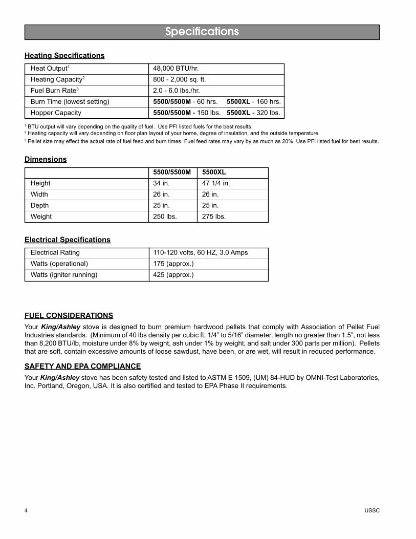
Specifications
HeatOutput1 48,000BTU/hr.Heating Capacity2 800-2,000sq.ft.Fuel Burn Rate3 2.0-6.0lbs./hr.BurnTime(lowestsetting) 5500/5500M-60hrs. 5500XL -160hrs.HopperCapacity 5500/5500M-150lbs. 5500XL-320lbs.
Heating Specifications
5500/5500M 5500XLHeight 34in. 471/4in.Width 26 in. 26 in.Depth 25 in. 25 in.Weight 250lbs. 275lbs.
Dimensions
1BTUoutputwillvarydependingonthequalityoffuel.UsePFIlistedfuelsforthebestresults.2Heatingcapacitywillvarydependingonfloorplanlayoutofyourhome,degreeofinsulation,andtheoutsidetemperature.3Pelletsizemayeffecttheactualrateoffuelfeedandburntimes.Fuelfeedratesmayvarybyasmuchas20%.UsePFIlistedfuelforbestresults.
Electrical Rating 110-120volts,60HZ,3.0AmpsWatts(operational) 175(approx.)Watts(igniterrunning) 425(approx.)
Electrical Specifications
FuEL CONSidErATiONSYourKing/Ashley stove is designed toburnpremiumhardwoodpellets thatcomplywithAssociationofPelletFuelIndustriesstandards.(Minimumof40lbsdensitypercubicft,1/4”to5/16”diameter,lengthnogreaterthan1.5”,notlessthan8,200BTU/lb,moistureunder8%byweight,ashunder1%byweight,andsaltunder300partspermillion).Pelletsthataresoft,containexcessiveamountsofloosesawdust,havebeen,orarewet,willresultinreducedperformance.
SAFETy ANd EPA COMPLiANCEYourKing/Ashley stove hasbeensafetytestedandlistedtoASTME1509,(UM)84-HUDbyOMNI-TestLaboratories,Inc.Portland,Oregon,USA.ItisalsocertifiedandtestedtoEPAPhaseIIrequirements.
USSC 5
iNSTALLATiON OPTiONSRead this entire manual before you install and use your King/Ashley stove. Failure to follow instructions may result in property damage, bodily injury, or even death!
(See specific installation details for clearances and other installation requirements)
AFreestanding Unit—supportedbypedestal/legsandplacedonanon-combustiblefloorsurfaceincompliancewithclearancerequirementsforafreestandingstoveinstallation.
AnAlcove Unit—supportedbypedestal/legsandplacedonanon-combustiblefloorsurfaceincompliancewithclearancerequirementsforanalcoveinstallation.
YourKing/Ashley stovemaybeinstalledtocodeineitheraconventionalormobile home (seeSPECIALMOBILEHOMEREQUIREMENTS).
ItisrecommendedthatonlyaauthorizedtechnicianinstallyourKing/Ashley stove,preferablyanNFIcertifiedspecialist.
Installation
iMPrOPEr iNSTALLATiON: Themanufacturerwillnotbeheldresponsiblefordamagecausedbythemalfunc-tionofastoveduetoimproperventingorinstallation.Call(800)750-2723and/orconsultaprofessionalinstallerifyouhaveanyquestions.
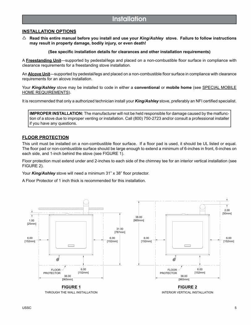
FLOOr PrOTECTiONThisunitmustbeinstalledonanon-combustiblefloorsurface.Ifafloorpadisused,itshouldbeULlistedorequal.Thefloorpadornon-combustiblesurfaceshouldbelargeenoughtoextendaminimumof6-inchesinfront,6-inchesoneachside,and1-inchbehindthestove(seeFIGURE1).
Floorprotectionmustextendunderand2-inchestoeachsideofthechimneyteeforaninteriorverticalinstallation(seeFIGURE2).
YourKing/Ashley stovewillneedaminimum31”x38”floorprotector.
AFloorProtectorof1inchthickisrecommendedforthisinstallation.
6 USSC
Installation
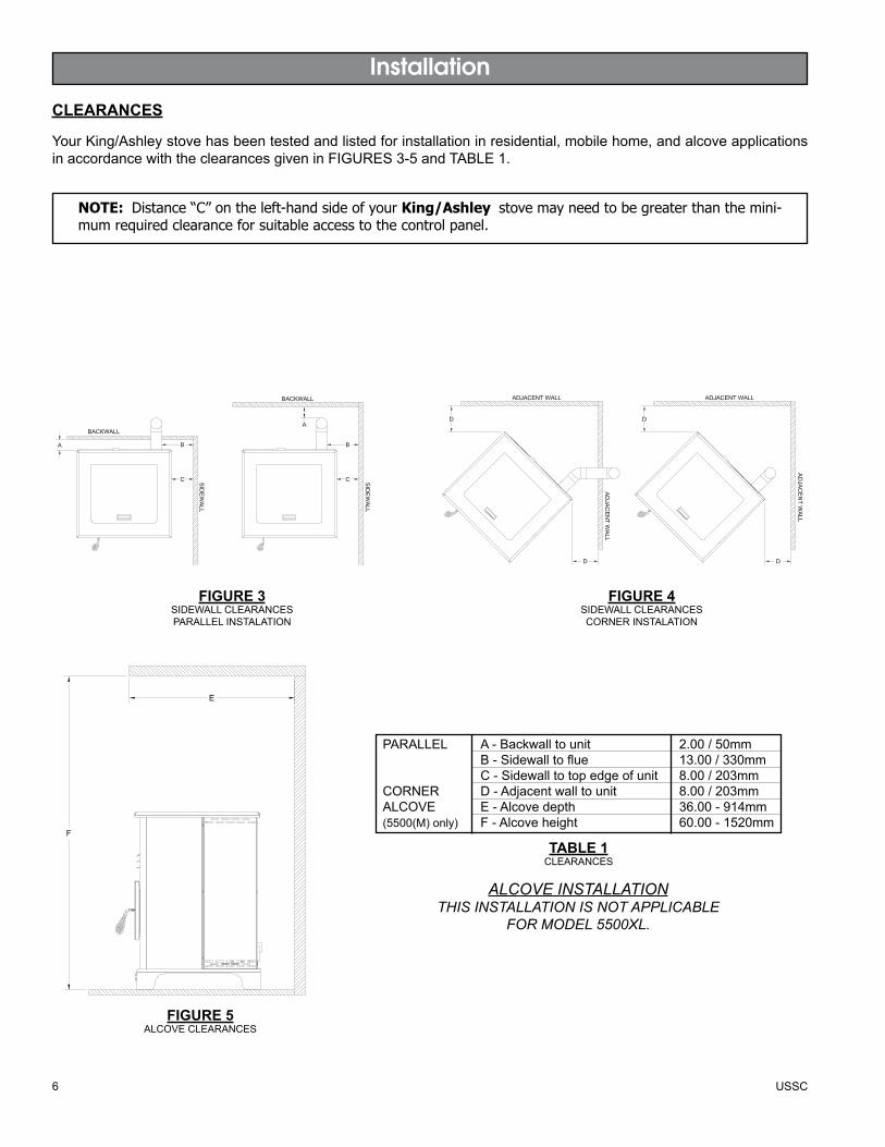
CLEArANCES
YourKing/Ashleystovehasbeentestedandlistedforinstallationinresidential,mobilehome,andalcoveapplicationsinaccordancewiththeclearancesgiveninFIGURES3-5andTABLE1.
NOTE: Distance “C” on the left-hand side of your King/Ashley stove may need to be greater than the mini-mum required clearance for suitable access to the control panel.
FigurE 3SIDEWALLCLEARANCESPARALLELINSTALATION
FigurE 4SIDEWALLCLEARANCESCORNERINSTALATION
FigurE 5ALCOVECLEARANCES
PARALLEL A-Backwalltounit 2.00/50mm B-Sidewalltoflue 13.00/330mm C-Sidewalltotopedgeofunit 8.00/203mmCORNER D-Adjacentwalltounit 8.00/203mmALCOVE E-Alcovedepth 36.00-914mm(5500(M)only) F-Alcoveheight 60.00-1520mm
TABLE 1CLEARANCES
ALCOVE INSTALLATIONTHIS INSTALLATION IS NOT APPLICABLE
FOR MODEL 5500XL.
USSC 7
Installation
vENTiNg rEquirEMENTSInstall vent at clearances specified by the vent manufacturer.
Do not connect the pellet vent to a vent serving any other appliance or stove.
Do not install a flue damper in the exhaust venting system of this unit.
Thefollowinginstallationguidelinesmustbefollowedtoensureconformitywithboththesafetylistingofthisstoveandtolocalbuildingcodes.
IMPORTANT! Thisunitisequippedwithanegativedraftsystemthatpullsairthroughtheburnpotandpushestheexhaustoutofthedwelling.Ifthisunitisconnectedtoafluesystemotherthanthewayexplainedinthismanual,itwillnotfunctionproperly.
MAXiMuM vENTiNg diSTANCEInstallationMUSTincludeatleast3-feetofverticalpipeoutsidethehome.Thiswillcreatesomenaturaldrafttoreducethepossibilityofsmokeorodorduringapplianceshutdownandkeepexhaustfromcausinganuisanceorhazardbyexposingpeopleorshrubstohightemperatures.Themaximumrecommendverticalventingheightis12-feetfor3-inchtype“PL”vent.TotallengthofhorizontalventMUSTNOTexceed4-feet.Thiscouldcausebackpressure.Usenomorethan180degreesofelbows(two90-degreeelbows,ortwo45-degreeandone90-degreeelbow,etc.)tomaintainadequatedraft.
PELLET vENT TyPEAULlisted3-inchor4-inchtype“PL”pelletventexhaustsystemmustbeusedforinstallationandattachedtothepipeconnectorprovidedonthebackofthestove(usea3-inchto4-inchadapterfor4-inchpipe).ConnectionatbackofstovemustbesealedusingHi-TempRTV.Use4-inchventiftheventheightisover12-feetoriftheinstallationisover2,500feetabovesealevel.
WerecommendtheuseofSimpsonDura-Vent®orMetal-Fab®pipe(ifyouuseotherpipe,consultyourlocalbuildingcodesand/orbuildinginspectors).DonotuseType-BGasVentpipeorgalvanizedpipewiththisunit.Thepelletventpipeisdesignedtodisassembleforcleaningandshouldbecheckedseveraltimesduringtheburningseason.Pelletventpipeisnotfurnishedwiththeunitandmustbepurchasedseparately.
PELLET vENT iNSTALLATiONTheinstallationmustincludeaclean-outteetoenablecollectionofflyashandtopermitperiodiccleaningoftheexhaustsystem.90-degreeelbowsaccumulateflyashandsoottherebyreducingexhaustflowandperformanceofthestove.Eachelboworteereducesdraftpotentialby30%to50%.
Alljointsintheventsystemmustbefastenedbyatleast3screws,andalljointsmustbesealedwithHi-TempRTVsiliconesealanttobeairtight.Theareawheretheventpipepenetratestotheexteriorofthehomemustbesealedwithsiliconeorothermeanstomaintainthevaporbarrierbetweentheexteriorandtheinteriorofthehome.
Ventsurfacescangethotenoughtocauseburnsiftouchedbychildren.Noncombustibleshieldingorguardsmayberequired.
PELLET vENT TErMiNATiONDonotterminatetheventinanenclosedorsemi-enclosedarea,suchas;carport,garage,attic,crawlspace,underasundeckorporch,narrowwalkway,oranyotherlocationthatcanbuildupaconcentrationoffumes.
Theterminationmustexhaustabovetheoutsideairinletelevation.
Theterminationmustnotbelocatedwhereitwillbecomepluggedbysnoworothermaterials.
Donotterminatetheventingintoanexistingchimney.
8 USSC
Installation
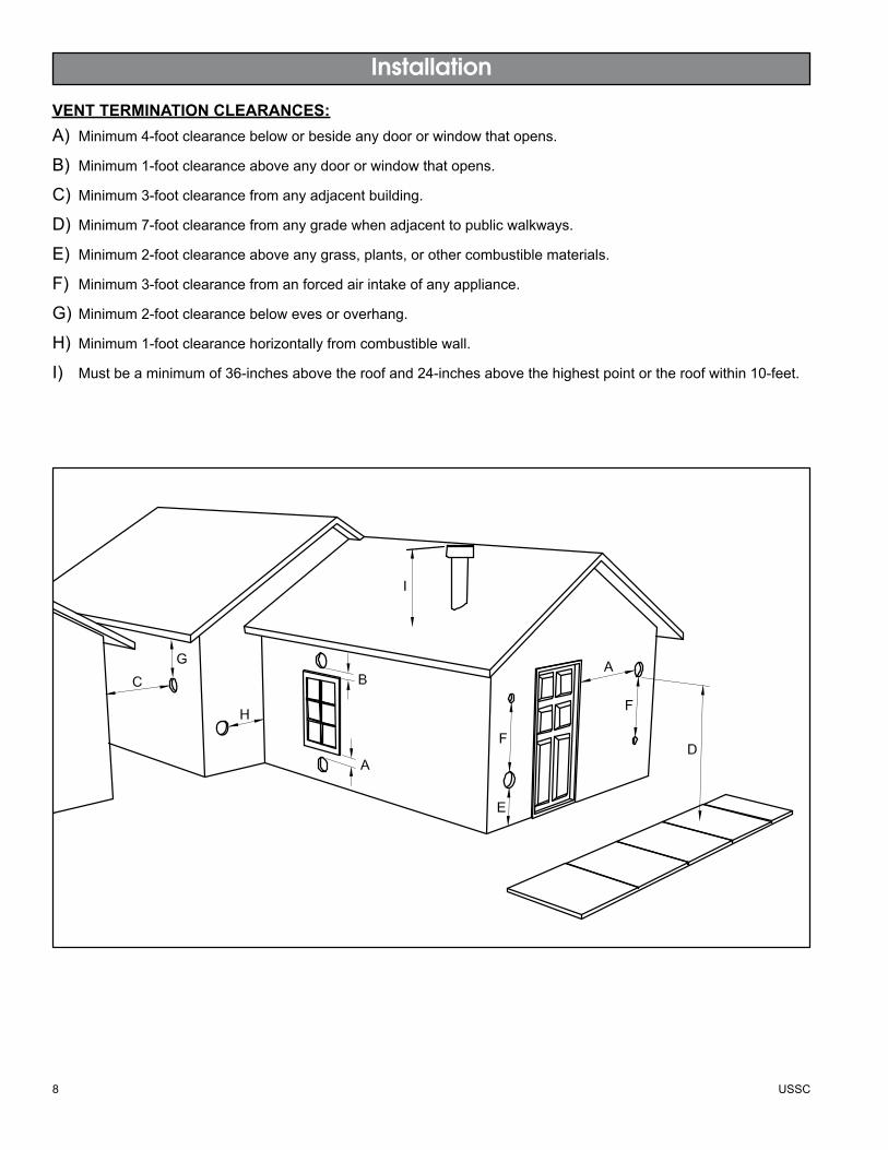
vENT TErMiNATiON CLEArANCES:A) Minimum4-footclearancebeloworbesideanydoororwindowthatopens.
B) Minimum1-footclearanceaboveanydoororwindowthatopens.
C) Minimum3-footclearancefromanyadjacentbuilding.
D) Minimum7-footclearancefromanygradewhenadjacenttopublicwalkways.
E) Minimum2-footclearanceaboveanygrass,plants,orothercombustiblematerials.
F) Minimum3-footclearancefromanforcedairintakeofanyappliance.
G)Minimum2-footclearancebelowevesoroverhang.
H) Minimum1-footclearancehorizontallyfromcombustiblewall.
I) Mustbeaminimumof36-inchesabovetheroofand24-inchesabovethehighestpointortheroofwithin10-feet.
G
USSC 9
Installation
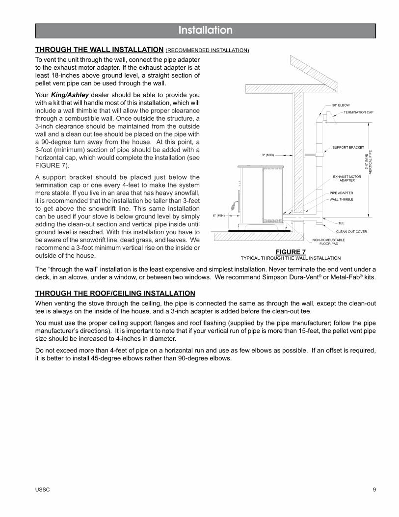
ThrOugh ThE wALL iNSTALLATiON (RECOMMENDEDINSTALLATION)Toventtheunitthroughthewall,connectthepipeadaptertotheexhaustmotoradapter.Iftheexhaustadapterisatleast18-inchesabovegroundlevel,astraightsectionofpelletventpipecanbeusedthroughthewall.
YourKing/Ashleydealershouldbeabletoprovideyouwithakitthatwillhandlemostofthisinstallation,whichwillincludeawallthimblethatwillallowtheproperclearancethroughacombustiblewall.Onceoutsidethestructure,a3-inchclearanceshouldbemaintainedfromtheoutsidewallandacleanoutteeshouldbeplacedonthepipewitha90-degree turnaway fromthehouse. At thispoint,a3-foot(minimum)sectionofpipeshouldbeaddedwithahorizontalcap,whichwouldcompletetheinstallation(seeFIGURE7).
A support bracket should be placed just below theterminationcaporoneevery4-feettomakethesystemmorestable.Ifyouliveinanareathathasheavysnowfall,itisrecommendedthattheinstallationbetallerthan3-feetto get above the snowdrift line.This same installationcanbeusedifyourstoveisbelowgroundlevelbysimplyaddingtheclean-outsectionandverticalpipeinsideuntilgroundlevelisreached.Withthisinstallationyouhavetobeawareofthesnowdriftline,deadgrass,andleaves.Werecommenda3-footminimumverticalriseontheinsideoroutsideofthehouse.
The“throughthewall”installationistheleastexpensiveandsimplestinstallation.Neverterminatetheendventunderadeck,inanalcove,underawindow,orbetweentwowindows.WerecommendSimpsonDura-Vent®orMetal-Fab®kits.
ThrOugh ThE rOOF/CEiLiNg iNSTALLATiONWhenventingthestovethroughtheceiling,thepipeisconnectedthesameasthroughthewall,excepttheclean-outteeisalwaysontheinsideofthehouse,anda3-inchadapterisaddedbeforetheclean-outtee.
Youmustusetheproperceilingsupportflangesandroofflashing(suppliedbythepipemanufacturer;followthepipemanufacturer’sdirections).Itisimportanttonotethatifyourverticalrunofpipeismorethan15-feet,thepelletventpipesizeshouldbeincreasedto4-inchesindiameter.
Donotexceedmorethan4-feetofpipeonahorizontalrunanduseasfewelbowsaspossible.Ifanoffsetisrequired,itisbettertoinstall45-degreeelbowsratherthan90-degreeelbows.
FigurE 7TYPICALTHROUGHTHEWALLINSTALLATION
10 USSC
Installation
OuTSidE Air SuPPLy (optional)Dependingonyourlocationandhomeconstruction,outsideairmaybenecessaryforoptimalperformance.
Metalpipe(solidorflexible)mustbeusedfortheoutsideairinstallation.PVCpipeisNOTapprovedandshouldNEVERbeused.
Awindshieldovertheterminationoftheoutsideairpipeora90-degreeelboworbendawayfromtheprevailingwindsMUSTbeusedwhenanoutsideairpipeisinstalledthroughthesideofabuilding.TheoutsideairterminationMUSTbeatleast1-footawayfromtheexhaustsystemtermination.
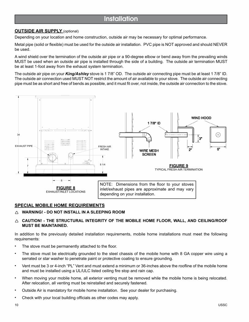
TheoutsideairpipeonyourKing/Ashley stoveis17/8”OD.Theoutsideairconnectingpipemustbeatleast17/8”ID.TheoutsideairconnectionusedMUSTNOTrestricttheamountofairavailabletoyourstove.Theoutsideairconnectingpipemustbeasshortandfreeofbendsaspossible,anditmustfitover,notinside,theoutsideairconnectiontothestove.
NOTE: Dimensions from the floor to your stovesinlet/exhaust pipesare approximateandmay varydependingonyourinstallation.
FigurE 9TYPICALFRESHAIRTERMINATION
FigurE 8EXHAUST/INLETLOCATIONS
SPECiAL MOBiLE hOME rEquirEMENTSWARNING! - DO NOT INSTAll IN A SlEEPING ROOM
CAUTION! - THE STRUCTURAl INTEGRITy OF THE MObIlE HOME FlOOR, WAll, AND CEIlING/ROOF MuST BE MAiNTAiNEd.
In addition to the previously detailed installation requirements,mobile home installationsmustmeet the followingrequirements:
Thestovemustbepermanentlyattachedtothefloor.
Thestovemustbeelectricallygroundedtothesteelchassisofthemobilehomewith8GAcopperwireusingaserratedorstarwashertopenetratepaintorprotectivecoatingtoensuregrounding.
Ventmustbe3or4-inch“PL”Ventandmustextendaminimumor36-inchesabovetherooflineofthemobilehomeandmustbeinstalledusingaUL/ULClistedceilingfirestopandraincap.
Whenmovingyourmobilehome,allexteriorventingmustberemovedwhilethemobilehomeisbeingrelocated.Afterrelocation,allventingmustbereinstalledandsecurelyfastened.
OutsideAirismandatoryformobilehomeinstallation.Seeyourdealerforpurchasing.
Checkwithyourlocalbuildingofficialsasothercodesmayapply.
•
•
•
•
•
•
USSC 11
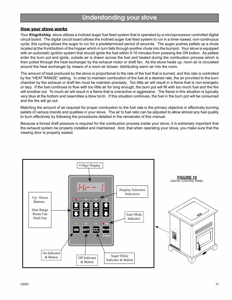
How your stove worksYourKing/Ashley stoveutilizesainclinedaugerfuelfeedsystemthatisoperatedbyamicroprocessorcontrolleddigitalcircuitboard.Thedigitalcircuitboardallowstheinclinedaugerfuelfeedsystemtoruninatimer-based,non-continuouscycle;thiscyclingallowstheaugertorunforapredeterminedperiodofseconds.Theaugerpushespelletsupachutelocatedatthefront/bottomofthehopperwhichinturnfallsthroughanotherchuteintotheburnpot.Yourstoveisequippedwithanautomaticignitionsystemthatshouldignitethefuelwithin5-10minutesfrompressingtheONbutton.Aspelletsentertheburnpotandignite,outsideairisdrawnacrossthefuelandheatedduringthecombustionprocesswhichisthenpulledthroughtheheatexchangerbytheexhaustmotorordraftfan.Asthestoveheatsup,roomairiscirculatedaroundtheheatexchangerbymeansofaroomairblower,distributingwarmairintotheroom.
Theamountofheatproducedbythestoveisproportionaltotherateofthefuelthatisburned,andthisrateiscontrolledbythe“HEATRANGE”setting.Inordertomaintaincombustionofthefuelatadesiredrate,theairprovidedtotheburnchamberbytheexhaustordraftfanmustbemaintainprecisely.Toolittleairwillresultinaflamethatisnon-energeticorlazy.Ifthefuelcontinuestoflowwithtoolittleairforlongenough,theburnpotwillfillwithtoomuchfuelandthefirewillsmotherout.Tomuchairwillresultinaflamethatisoveractiveoraggressive.Theflameinthissituationistypicallyveryblueatthebottomandresemblesablowtorch.Ifthissituationcontinues,thefuelintheburnpotwillbeconsumedandthefirewillgoout.
Matchingtheamountofairrequiredforpropercombustiontothefuelrateistheprimaryobjectiveineffectivelyburningpelletsofvariousbrandsandqualitiesinyourstove.Theairtofuelratiocanbeadjustedtoallowalmostanyfuelqualitytoburneffectivelybyfollowingtheproceduresdetailedintheremainderofthismanual.
Becauseaforceddraftpressureisrequiredforthecombustionprocessinsideyourstove,itisextremelyimportantthattheexhaustsystembeproperlyinstalledandmaintained.And,thatwhenoperatingyourstove,youmakesurethattheviewingdoorisproperlysealed.
Understanding your stove
4 Digit Display
Up / DownButtons :
Heat RangeRoom FanDraft Fan
Auto ModeIndicator
Auger DelayIndicator & ButtonOff Indicator
& Button
On Indicator& Button
FigurE 10DIGITALCONTROLPANEL

12 USSC
Control Panel Overview
ON/OFFPressingthe“ON”buttononthecontrolpanelwillbeginthestart-upsequencefortheheater.Fuelwillbegintofeedthroughtheaugerfeedsystemafter3minutes.Pressingandholdingthe“ON”buttonwillrotatetheaugercontinuouslyuntilbuttonisreleased,whichfeedsadditionalfuel.Pressingthe“OFF”buttononthecontrolpanelwillcausetheheatertoenteritsshut-downsequence.Thefuelfeedsystemwillstoppullingfuelfromthehopperand,oncethefiregoesoutandtheheatercoolsdown,thefanswillstoprunning.hEAT rANgEPressingthe“HeatRange”arrows,upordown,willadjusttheamountoffuelbeingdeliveredtotheburnpot.drAFT FANThedraftfan(exhaust)willcomeonassoonasthe“ON”buttonispressed.Thefanwillautomaticallyadjustitsspeedinaccordancetotheheatrangesetting.However,thisspeedcanbemanuallyoperatedbypressingthe“DraftFan”arrowsupordown.“DraftFan”whenpressed,thedisplaywillshow“Df-A”,whichisautomatic.Pressthearrowsagaintoadjustfanspeed.Whentheheaterisinthemanualmode,theoptionalthermostatwillnotproperlycontroltheunit.WhenadjustingtheDraftFansetting,tryonly1settingaboveorbelowtheheatsetting.Itisbettertoleavethestoveintheautomaticmode.rOOM FANTheroomfanwillcomeononcetheunithasreachedoperatingtemperature.Bypressingthe“RoomFan”buttons,thedisplaywillshow“Rf-A”whichisautomaticor“Rf-1”through“Rf-9”formanualsettings.Inautomode,theroomfan’sspeedwillautomaticallybeadjustedinaccordancewiththeheatrangesetting.Bypressingthe“RoomFan”uparrow,youcanadjustthefanspeedsettingupto“Rf-9”.Theroomfanmustoperateatalevelgreaterthanorequaltotheheatrangesetting.AuX-USEDTORETURNTHESTOVETOTHEFACTORYSETTINGSToreturnthestovetoit’soriginalfactorysettings,pressandholdtheAUXUPandAUXDOWNbuttonssimultaneouslyfor3seconds.AugEr dELAyThe“AugerDelay”buttoncanbeusedtopauserotationoftheAugerforapprox.1minute.Thiscanbecancelledbypressingthe“ON”button.The“AugerDelay”isnormallyusedonlyduringthestartupcycletoslowthefueldeliverydownduringtheinitialignition.MOdEThe“Mode”buttonisusedtoswitchbetweenmanualandautomaticmode.Wheninautomode,thefansandaugerwilloperateatpresetintervalsunlesschangedmanuallyusingthebuttonsmentionedabove.Wheninmanualmode,thedraftfan(exhaust)willoperateatfullspeed(100%).Duringnormaloperation,theunitisconstantlymonitoredforproblems.Intheeventofanerrorcondition,theunitwillstopandanerrorwillbedisplayed.Seethelistoferrorcodesfoundattheendofthismanual.
TurningtheheaterON/OFF,aswellasadjustmentsforthefuelfeedrateandroomfanspeedareperformedbypressingtheappropriatebutton(s)onthecontrolpanelwhichislocatedonthelowerleft-handsideofyourheater.Thisunitcanbechangedbetweenanautomaticoperationoramanualoperation.Thecontrollercomesdefaultintheautomaticmode.
•
•
•
•
•
•
•
USSC 13
uNiT PrEPArATiONAftercarefullyunpackingandreadingtheinstructionsforinstallingyourstove,youwillneedtoperformthefollowingsteps:
Attachtheincludedspringhandletothedoorhandlebyscrewingitoninarespectivelocation.
Attachtheelectricalcordtothebackofthestovefirst;thenplugitintoa110-voltoutlet(anoutletsurgeprotectorishighlyrecommended).
PErFrOMiNg AN iNTiAL TESTThistestisusedatthefactorywherethestovesareassembledtotestthefunctionalityofthecontrolandthestovebeforetheunitisshipped.Toperformthistest,pressandholdtheOFFandAUGERDELAYbuttonssimultaneouslyfor3seconds.Toadvancethroughthetest,pressanykeyunlessotherwisenotedintheteststep.
ExhaustFanOutputTest–Thedisplaywillshow“drft”.Theexhaustfanisturnedonfullthenreducedtoaleveljustabovethetypicalminimumpressureswitchsetting.TheONLEDindicateswhetherthepressuresensorisdetected.Ifthepressureswitchisnotdetected,thefanrampstofullonfortwosecondsthenreturnstothepreviouslyestablishedlevelifthepressureswitchcloses.IftheDraftFanFuseisnotblownandthefusedetectioncircuitisfunctioning,theDraftFanLEDwillbelitandtheotherthreetoprowLEDswillbeoff.RoomFanOutputTest-Thedisplaywillshow“rfan”.Theroomfanisturnedonfull.IftheRoomFanFuseisnotblownandthefusedetectioncircuitisfunctioning,theRoomFanLEDwillbelitandtheotherthreetoprowLEDswillbeoff.IgnitorOutputTest-Thedisplaywillshow“ignt”.Theignitormotoristurnedonfull.IftheIgnitor(AUX)Fuseisnotblownandthefusedetectioncircuitisfunctioning,theAuxLEDwillbelitandtheotherthreetoprowLEDswillbeoff.AugerOutputTest-Thedisplaywillshow“augr”.Theaugermotoristurnedonfull.IftheAugerFuseisnotblownandthefusedetectioncircuitisfunctioning,theHeatRangeLEDwillbelitandtheotherthreetoprowLEDswillbeoff.HopperSwitchTest–Thedisplaywillshow“hppr”.The“ON”LEDislit.Ifthehopperswitchisopen(lidisopen),the“HEATRANGE”LEDwillturnon.Ifthelidisclosed,the“HEATRANGE”LEDwillbeoff.ThermostatInputTest–Thedisplaywillshow“stat”.Ifthethermostat inputisclosed,theONLEDwill turnon,otherwiseitwillbeoff.FluegasThermistorTest–ThedisplaywillshowthefluegastemperatureindegreesF.ACFrequencyTest-DisplaysthemeasuredACFrequencyinhertzfollowedbytheletter‘H’.WatchdogReset–Thewatchdogtimeristestedtoensurethattheboardcanbereset.Themessage“BYE”isdisplayeduntilthewatchdogresetstheboard.
•
•
Operation
1.)
2.)
3.)
4.)
5.)
6.)
7.)8.)9.)
PErFOrMiNg A “dry ruN”Performa“dryrun”onyourstovepriortomakingtheexhaust/inletconnectionsandstartingyourstoveforthefirsttime.
CheckthatthereisNOfuelorANYforeignmaterialinthehopperorburn-pot.
Checkthattheviewingdoorandhopperlidissecurelyclosed.
Pressthe“ON”buttononthecontrolpanel.VerifythattheONLEDislit(blinking)andthedisplayshowsHR-1.AlsotheLEDabovetheHEATRANGEandtheAUTOMODEindicatorshouldbelit.IfanyotherLED’sarelitorflashing,consultthe“DisplayIndicators”inthismanual.
Youshouldheartheexhaust(draft)fanrunningimmediatelyandtheaugershouldbeginturningcontinuouslyfor1minute.
Theautofuelignitor(locatedinsidethebackwalloftheburnpot)shouldbegintoglowred/orangeafter3minutes.
TheRoomFanwillnotoperateatthistimesincetheunitmustreachafactorypresettemperature.
DONOTopentheviewingdoor,theauto-start igniter willgetveryhotduringthistest.Thestovewillautomaticallyshutdownafterapproximately23minutes.
1.)
2.)
3.)
4.)
5.)
6.)
14 USSC
ShuT dOwN PrOCEdurE
Pressthe“OFF” buttononthecontrolpadtoputthestoveinshutdownmode.Atthistime,theredlightabovethepadwillilluminate.Oncethisisdone,theaugerwillstopfeedingpellets,butthedistributionblowerandexhaustblowerwillcontinuetooperate.Whentheinternaltemperatureoftheunitdropsbelowthefactorypresettemperature,thedistributionblowerandexhaustblowerwillceasetooperate.Theredlightwillthenshutoffandtheunitwillbecompletelyshutdown.
Thehottertheunitisduringitsoperation,thelongeritwilltakeforthestovetocompletetheshutdowncycle.Ifthestovestaysonformorethan2hoursafterpressingthe“OFF” buttonandyouaresurethatthefireisout,thestovecanbeunpluggedfromtheoutlet.Afterapproximately10seconds,theunitcanbere-connectedtothepowersourceandthecontrolboardwillbereset.
Operation
STArT-uP PrOCEdurENever use gasoline, gasoline-type lantern fuel, kerosene, charcoal lighter fluid, or similar liquids to start or “freshen up” a fire in this stove. Keep all such liquids well away from the stove while it is in use.
Verifythatthehopperiscleanandfreeofforeignmatter.
Verifythatalloftherequiredexhaust/inletconnectionshavebeenmadeinaccordancewiththismanualandthatthestoveispluggedintoanoutlet(anoutletsurgeprotectorishighlyrecommended).
Fillthehopperwithwoodpellets;donotallowanypartofthebagoranyotherforeignmaterialintothehopper,asthismayjamtheauger.
Ensurethatallpelletmatterisclearedfromthehopperseatingsurface.
Closethehopperlid.The unit WIll NOT feed fuel with the hopper lid open.
Makesurethattheviewingdoorissecurelyclosed(thesafetypressureswitchwillnotallowthestovetofeedfuelifthereisnodraftpressureinsidethestove).
Pressthe“ON” buttononthecontrolpadandsetthe“hEAT SETTiNg” toyourdesiredsetting.
Thestovewillbegintofeedfuelandtheauto-start igniter willignitethefuelinapproximately5minutes.
Onceaconsistentflamehasbeenestablished,youcanadjustthe“HEATRANGE”and“BLOWERSPEED”onthecon-trolpadtoyourdesiredsettings.(Note:Thedistributionblowerwillnotfunctionuntiltheheatexchangerinthestovereachesthefactorypresettemperature).
1.)
2.)
3.)
4.)
5.)
6.)
7.)
8.)
First Fire: Adjustthe“hEAT rANgE” and“BLOwEr SPEEd” toa“3” settingandallowthestovetooperateinthismannerforapproximatelythree(3)hours(ormoreifnecessary),allowingthestoveto“cureout”asthepaintandoilsfromthemanufacturingprocessburnoff.Werecommendthatyouopen
doorsandwindowsinyourhomeduringthisprocess.Adjustsettingtodesiredsetting.
WARNING: Never shut down this unit by unplugging it from the power source.
USSC 15
Maintenance
Operation
dAiLy OPErATiONThe hopper and stove top will be hot during operation; therefore, you should always use some type of hand protection when refueling your stove.
Never place your hand near the auger while the stove is in operation.
Thisunitshouldbefilledwhenthehopperleveldropsbelow3-inches.
Intheeventofapower outage,thestoveWILLNOTfunction.Itisveryimportantthatunitbeventedproperly(withoutsideair),asthenaturaldraftisneededtoclearthesmokefromthestoveduringapoweroutage.Iftheunitwas“ON” whenthepoweroutageoccurred,oneofthefollowingwilltakeplace:
Ifthestoveisstillwarm,itwillresumefeedingfuelandcontinuetooperatenormally.Ifthefirehasgoneout,youwillhavetopressthe“OFF” buttonandthenthe“ON” buttonagaintobeginanewstart-upsequence.
Ifthestovehascooled-off,itwillresettoits“OFF” condition.Atthispoint,youmaypressthe“ON” buttonandtheunitwillbeginanewstart-upsequence.
NOTE:Theunitwillalsoshutdownintheeventofanexhaustblowerfailure;ifthisisthecase,theunitwillnotre-startandyoumustcontactCustomerServiceat(800)750-2723.
SAFETy ANd CONvENiENCE FEATurESYourKing/Ashley incorporatesasafety pressure switch thathelpsensurethateverythingisinproperworkingorderbeforefeedingfueltotheburnpot.Becausethestoveworksusinganinduceddraftpressure,thestovewillnotcontinuetooperateiftheviewingdoorisleftopen;oriftheexhaustblowerfailsortheexhaustsystemisblocked.
Thetemperature limit control willpreventyourstovefromoperatingatabnormallyhightemperatures.Shouldthestovetemperaturebegintoapproachthefactorypre-setlimit,thetemperaturelimitcontrolwillautomaticallyslowdowntheaugerfeedrateuntilthetemperaturereturnstoanormalcondition.Eventhoughtheheaterwilloperateonsetting“5”(HI),werecommendtooperateyourheateronthissettingforonlyashortperiodoftime.(1houretc.)
YourKing/Ashley stovealsoincludesanauto-start igniter asastandardfeature.Theuseofotherfirestartermaterials(woodchips,startergel,etc.)isnotnecessary.Bysimplypressingthe“ON”buttononthedigitalcontrolpanel,yourstovewillbegintofeedfuelandautomaticallystartwithin5minutes.
1.)
2.)
Failure to clean and maintain this unit as indicated can result in poor performance and safety hazards.
Unplug your stove’s electrical cord prior to removing the back panel or opening the exhaust system for any inspection, cleaning, or maintenance work.
Never perform any inspections, cleaning, or maintenance on a hot stove.
Do not operate stove with broken glass , leakage of flue gas may result.
EXhAuST SySTEMThebyproductsofcombustioncontainsmallparticlesofflyash.Flyashwillcollectintheexhaustventingsystemandrestricttheflowoffluegases.Incompletecombustion,suchasduringstartup,shutdown,orincorrectoperationofthestovewillleadtosootformationwhichwillcollectintheexhaustsystem.Therefore,itisimportantthattheexhaustsystembeinspected and cleaned at least monthly duringtheburningseason.
Checkthecleanoutteesperiodicallytodeterminetherequiredcleaningschedule.3or4-inchchimneybrushesareavailableforchimneycleaning.Iftheexhaustsystemoroutsideairpipeshavescreensonthem,frequentlycleanthescreen.Apluggedscreenwillshutoffcombustionairandcauseafiretodieorburnpoorly.

16 USSC
iNTEriOr ChAMBErS
Periodicallyremoveandcleantheburnpotandtheareainsidetheburnpothousing.Inparticularitisadvisabletocleanouttheholesintheburnpottoremoveanybuildupthatmaypreventairfrommovingthroughtheburnpotfreely.Removethetwo(2)platesoneachsideoftheburnpothousingandcleanoutthatrearchamber.
Ifavacuumisusedtocleanyourstove,wesuggestusingavacuumdesignedforashremoval.Someregularvacuumcleaner(i.e.shopvacs)mayleakashintotheroom.
ASh diSPOSAL
Ashesshouldbeplacedinametalcontainerwithatightfittinglid.Theclosedcontainerofashesshouldbeplacedonanoncombustiblefloororontheground,wellawayfromallcombustiblematerials,pendingfinaldisposal.Iftheashesaredisposedofbyburialinsoilorotherwiselocallydispersed,theyshouldberetainedintheclosedcontaineruntilallcindershavebeenthoroughlycooled.
CHECK AND ClEAN THE HOPPER
Checkthehopperperiodicallytodetermineifthereisanysawdustorpelletsthatarestickingtothehoppersurface.Cleanasneeded.
DOOR AND GlASS GASKETS
Inspectthemaindoorandglasswindowgasketsperiodically.Themaindoormayneedtoberemovedtohavefrayed,broken,orcompactedgasketsreplacedbyyourAuthorized“King/Ashley”Dealer.Theglassgaskethasagapatthebottomfortheairwash.
BLOwEr MOTOrS
Cleantheairholesonthemotorsofboththeexhaustanddistributionblowersannually.Removetheexhaustblowerfromtheexhaustductandcleanouttheinternalfanbladesaspartofyourfallstart-up.
PAiNTEd SurFACES
Paintedsurfacesmaybewipeddownwithadampcloth.Ifscratchesappear,oryouwishtorenewyourpaint,contactyourAuthorized“King/Ashley”Dealertoobtainacanofsuitablehigh-temperaturepaint.
gLASS
Werecommendusingahighqualityglasscleaner.Shouldabuildupofcreosoteorcarbonaccumulate,youmaywishtouse000steelwoolandwatertocleantheglass.Intheeventyouneedtoreplacetheglass,onlyhightemperatureceramicglassofthecorrectsizeandthicknessmaybeused.ContactyourAuthorized“King/Ashley”Dealertoobtainthisglass.
FALL STArT uP
Priortostartingthefirstfireoftheheatingseason,checktheoutsideareaaroundtheexhaustandairintakesystemsforobstructions.Cleanandremoveanyflyashfromtheexhaustventingsystem.Cleananyscreensontheexhaustsystemandontheoutsideairintakepipe.Turnallofthecontrolsonandmakesurethattheyareworkingproperly.Thisisalsoagoodtimetogivetheentirestoveagoodcleaningthroughout.
SPriNg ShuTdOwN
Afterthelastburninthespring,removeanyremainingpelletsfromthehopperandtheaugerfeedsystem.Scoopoutthepelletsandthenruntheaugeruntilthehopperisemptyandpelletsstopflowing(thiscanbedonebypressingthe“ON” buttonwiththeviewingdooropen).Vacuumoutthehopper.Thoroughlycleantheburnpot,andfirebox.Itmaybedesirabletospraytheinsideofthecleanedhopperwithanaerosolsiliconesprayifyourstoveisinahighhumidityarea.Theexhaustsystemshouldbethoroughlycleaned.
yEArLy SErviCiNg
AyearlyservicingandcleaningbyyourAuthorized“King/Ashley”Dealerisrecommended.Afeemaybechargedforthisservice.
Maintenance
USSC 17
Trouble Shooting
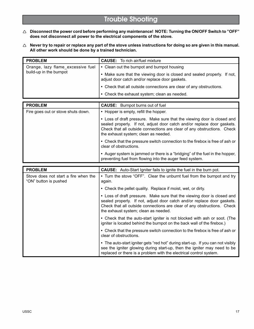
Disconnect the power cord before performing any maintenance! NOTE: Turning the ON/OFF Switch to ”OFF” does not disconnect all power to the electrical components of the stove.
Never try to repair or replace any part of the stove unless instructions for doing so are given in this manual. All other work should be done by a trained technician.
PrOBLEM CAuSE:Torichair/fuelmixtureOrange, lazy flame_excessive fuelbuild-upintheburnpot
• Cleanouttheburnpotandburnpothousing
• Makesurethattheviewingdoorisclosedandsealedproperly.Ifnot,adjustdoorcatchand/orreplacedoorgaskets.
• Checkthatalloutsideconnectionsareclearofanyobstructions.
• Checktheexhaustsystem;cleanasneeded.
PrOBLEM CAuSE:BurnpotburnsoutoffuelFiregoesoutorstoveshutsdown. • Hopperisempty,refillthehopper.
• Lossofdraftpressure.Makesurethattheviewingdoorisclosedandsealedproperly. If not, adjustdoor catchand/or replacedoorgaskets.Checkthatalloutsideconnectionsareclearofanyobstructions.Checktheexhaustsystem;cleanasneeded.
• Checkthatthepressureswitchconnectiontothefireboxisfreeofashorclearofobstructions.
• Augersystemisjammedorthereisa“bridging”ofthefuelinthehopper,preventingfuelfromflowingintotheaugerfeedsystem.
PrOBLEM CAuSE:Auto-StartIgniterfailstoignitethefuelintheburnpot.Stovedoesnot start a firewhen the“ON”buttonispushed
• Turnthestove“OFF”.Cleartheunburntfuelfromtheburnpotandtryagain.
• Checkthepelletquality.Replaceifmoist,wet,ordirty.
• Lossofdraftpressure.Makesurethattheviewingdoorisclosedandsealedproperly. If not, adjustdoor catchand/or replacedoorgaskets.Checkthatalloutsideconnectionsareclearofanyobstructions.Checktheexhaustsystem;cleanasneeded.
• Check that theauto-start igniter isnotblockedwithashorsoot. (Theigniterislocatedbehindtheburnpotonthebackwallofthefirebox.)
• Checkthatthepressureswitchconnectiontothefireboxisfreeofashorclearofobstructions.
• Theauto-startignitergets“redhot”duringstart-up.Ifyoucannotvisiblysee the igniterglowingduringstart-up, then the ignitermayneed tobereplacedorthereisaproblemwiththeelectricalcontrolsystem.
18 USSC
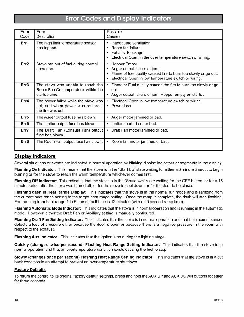
ErrorCodeErr1
Err2
Err3
Err4
Err5Err6Err7
Err8
ErrorDescrptionThehighlimittemperaturesensorhastripped.
Stoveranoutoffuelduringnormaloperation.
The stovewas unable to reach theRoomFanOntemperaturewithinthestartuptime.Thepowerfailedwhilethestovewashot, andwhen powerwas restored,thefirewasout.TheAugeroutputfusehasblown.TheIgnitoroutputfusehasblown.TheDraft Fan (Exhaust Fan) outputfusehasblown.TheRoomFanoutputfusehasblown.
PossibleCauses• Inadequateventilation.• Roomfanfailure.• ExhaustBlockage.• ElectricalOpenintheovertemperatureswitchorwiring.• HopperEmpty.• Augeroutputfailureorjam.• Flameoffuelqualitycausedfiretoburntooslowlyorgoout.• ElectricalOpeninlowtemperatureswitchorwiring.• FlameorFuelqualitycausedthefiretoburntooslowlyorgo out.• AugeroutputfailureorjamHopperemptyonstartup.• ElectricalOpeninlowtemperatureswitchorwiring.• Powerloss
• Augermotorjammedorbad.• Ignitorshortedoutorbad.• DraftFanmotorjammedorbad.
• Roomfanmotorjammedorbad.
Display IndicatorsSeveralsituationsoreventsareindicatedinnormaloperationbyblinkingdisplayindicatorsorsegmentsinthedisplay:Flashing On Indicator:Thismeansthatthestoveisinthe“StartUp”statewaitingforeithera3minutetimeouttobeginburningorforthestovetoreachthewarmtemperaturewhichevercomesfirst.Flashing Off Indicator:Thisindicatesthatthestoveisinthe“Shutdown”statewaitingfortheOFFbutton,orfora15minuteperiodafterthestovewasturnedoff,orforthestovetocooldown,orforthedoortobeclosed.Flashing dash in Heat Range Display:Thisindicatesthatthestoveisinthenormalrunmodeandisrampingfromthecurrentheatrangesettingtothetargetheatrangesetting.Oncetherampiscomplete,thedashwillstopflashing.Forrampingfromheatrange1to5,thedefaulttimeis12minutes(witha90secondramptime).Flashing Automatic Mode Indicator:Thisindicatesthatthestoveisinnormaloperationandisrunningintheautomaticmode.However,eithertheDraftFanorAuxiliarysettingismanuallyconfigured.Flashing Draft Fan Setting Indicator:Thisindicatesthatthestoveisinnormaloperationandthatthevacuumsensordetectsalossofpressureeitherbecausethedoorisopenorbecausethereisanegativepressureintheroomwithrespecttotheexhaust.
Flashing Aux Indicator: Thisindicatesthattheignitorisonduringthelightingstage.
Quickly (changes twice per second) Flashing Heat Range Setting Indicator: This indicatesthatthestoveis innormaloperationandthatanovertemperatureconditionexistscausingthefueltostop.
Slowly (changes once per second) Flashing Heat Range Setting Indicator: Thisindicatesthatthestoveisinacutbackconditioninanattempttopreventanovertemperatureshutdown.
Factory DefaultsToreturnthecontroltoitsoriginalfactorydefaultsettings,pressandholdtheAUXUPandAUXDOWNbuttonstogetherforthreeseconds.
Error Codes and Display Indicators

USSC 19
13
5
11
10
110
1210
6
12
78
2
4
3
9
9
9
Parts Diagram/List models 5500, 5500M & 5500XL
113
2
15
64
7
98
10
12
Item Part No. Title Qty.1 25490 DoorWeldment 12 891166 CeramicGlass 13 891188 GlassRetainer,Top 14 891186 GlassRetainer,Bottom 15 25517 Handle,Door 16 891168 Latch,Door 17 88082 3/4”RopeGasket 4.3ft
PARTSLISTItem Part No. Title Qty.8 88087 GlassGasket 3.75ft9 83297 8-32HexNut 310 83547 Washer 311 83903 Spring 112 83546 5/16x18HexJambNut 213 891167 SpringHandle 1
Item Part No. Title Qty.1 25507 FeedDoor 12 25492 Handle,Door 13 83506 3/8x11/4RollPin 14 891067 DoorGlassw/AshleyLogo 15 88066 5/8”RopeGasket 4.5ft6 88087 GlassGasket(1x13/16) 3.5ft7 25520 BottomGlassRetainer 18 25521 TopGlassRetainer 1
PARTSLISTItem Part No. Title Qty.9 83278 Washer 410 83202 MachineScrew 411 89574 SpringHandle 112 25393 Retainer,Glass(AlternateFor7&8) 1N/S 25080MB DoorLatch 1N/S 83508 5/16-18x1-3/4Bolt 1N/S 83338 5/16-18Lock-Nut 1N/S-NotShown
Model 5500
Model 5500M/5500Xl
20 USSC
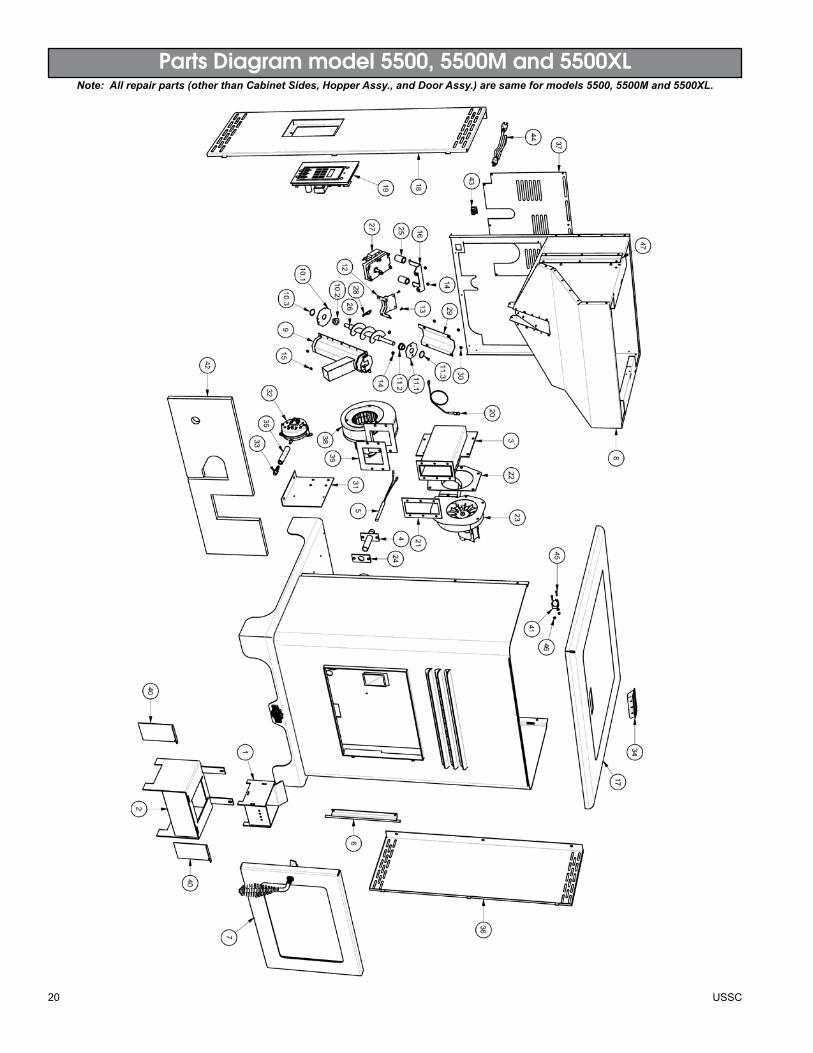
Parts Diagram model 5500, 5500M and 5500XLNote: All repair parts (other than Cabinet Sides, Hopper Assy., and Door Assy.) are same for models 5500, 5500M and 5500XL.

USSC 21
Parts List model 5500/5500M/5500XL
Item Part No. Title Qty.1 86624 BurnpotAssembly 12 86625 HousingAssy,Burnpot 13 86628 Weldment,ExhaustDuct 14 86633 Weldment,IgniterTube 15 80481 IgniterCartridge 16 25506 Weldment,DoorHinge 17 69512 DoorAssembly 18 69518 HopperAssembly(5500) 1- 69522 HopperAssembly(5500XL) 19 891164 WeldmentAugerHousing 110 69513 Assy.,BushingRetainerBottom 110.1 891190 Plate,BottomBushing 110.2 891132 Bushing 110.3 83534 Retaining Ring 111 69514 Assy.,BushingRetainerTop 111.1 891189 Plate,TopBushing 111.2 891132 Bushing 111.3 83534 Retaining Ring 112 891161 Weld.,Bot.PlateRetainer 113 83543 6-32x3/8MachineScrew 214 83356 10-32HexNut 415 83299 6-32HexNut 216 891195 Bracket,DriveMotor 117 25498 Weldment,TopLid 118 25511 Weld,LeftSideCabinet(5500) 1- 25515 Weld,LeftSideCabinet(5500XL) 119 80558 CircuitBoardAssembly 120 80480 Thermistor 121 88117 Gasket,ExhaustDuct 122 88100 Gasket,ExhaustBlower 1
PARTSLISTItem Part No. Title Qty.23 80473 Blower,Exhaust 124 88118 Gasket,IgniterFlange 125 891169 Hose,Heater 1.5in26 891141 Auger 127 80488 DriveMotor 128 83529 Hairpin 129 891180 Cover,Auger 130 83297 8-32HexNut 431 891187 Bracket,PressureSwitch/PCB 132 80549 PressureSwitch 133 89586 Nipple 134 891148 Handle,Plastic 135 891121 SiliconeTube 3in.36 25512 Side,RightCabinet(5500) 1- 25516 Side,RightCabinet(5500XL) 137 25510 Panel,Access 138 80472 Blower,Distribution 139 88106 Gasket,DistributionBlower 140 25513 Cleanout,Ash 241 80491 Microswitch 142 88119 Insulation,Blanket 243 80462 Receptacle,3Prong 144 80461 PowerSupplyCord 145 83516 #4-40MachineScrew 246 83542 #4-40NylonLockNut 247 89390A RubberGrommet 1N/S 80548 WiringHarness 1
22 USSC
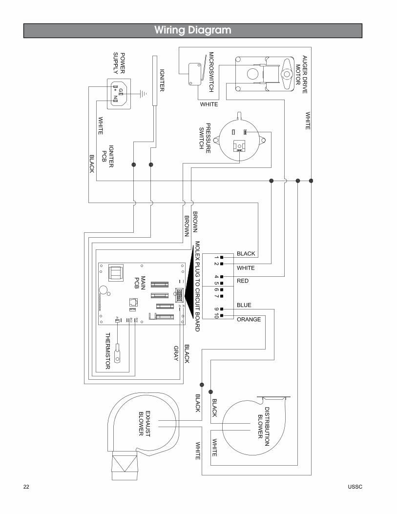
Wiring Diagram
GR
AY
BLA
CK
USSC 23
Notes

24 USSC
This manual will help you obTain efficienT, dependable ser-vice from your KinG or ashley, and enable you To order repair
parTs correcTly.
Keep This manual in a safe place for fuTure reference.
when wriTinG, always Give The full model number which is on The nameplaTe aTTached To The heaTer.
when orderinG repair parTs, always Give The followinG infor-maTion as shown in This lisT:
1. The parT number
2. The parT descripTion
3. The model number: 5500 5500m 5500Xl
4. The serial number:____________________
How to order repair parts
united states stove company227 industrial park road
p.o. box 151south pittsburg, Tn 37380
(800) 750-2723www.ussTove.com
CSSUCOMPANY
UNITED STATES STOVE


![THE INDIAN DIVORCE ACT, 1869 INDIAN DIVORCE ACT, 1869 Preamble 1 - DIVORCE ACT, 1869 THE INDIAN DIVORCE ACT, 18691 [Act, No. 4 of 1869] [26th February, 1869] PREAMBLE An Act to amend](https://img.pdfslide.net/doc/110x75/5aae50507f8b9a3a038bffdb/the-indian-divorce-act-indian-divorce-act-1869-preamble-1-divorce-act-1869.jpg)