Embed Size (px)
Citation preview
K126-102-001-012KELOWNA Flightcraft Ltd.
MAINTENANCE MANUAL SUPPLEMENT
SAMPLECL-415 AUTOPILOT AND FMS INSTALLATION
AUTOMATIC FLIGHT CONTROL SYSTEM – DESCRIPTION AND OPERATION
1. Description and Operation
Refer to Figure 1.
A. Automatic Flight Control System (AFCS) – Description
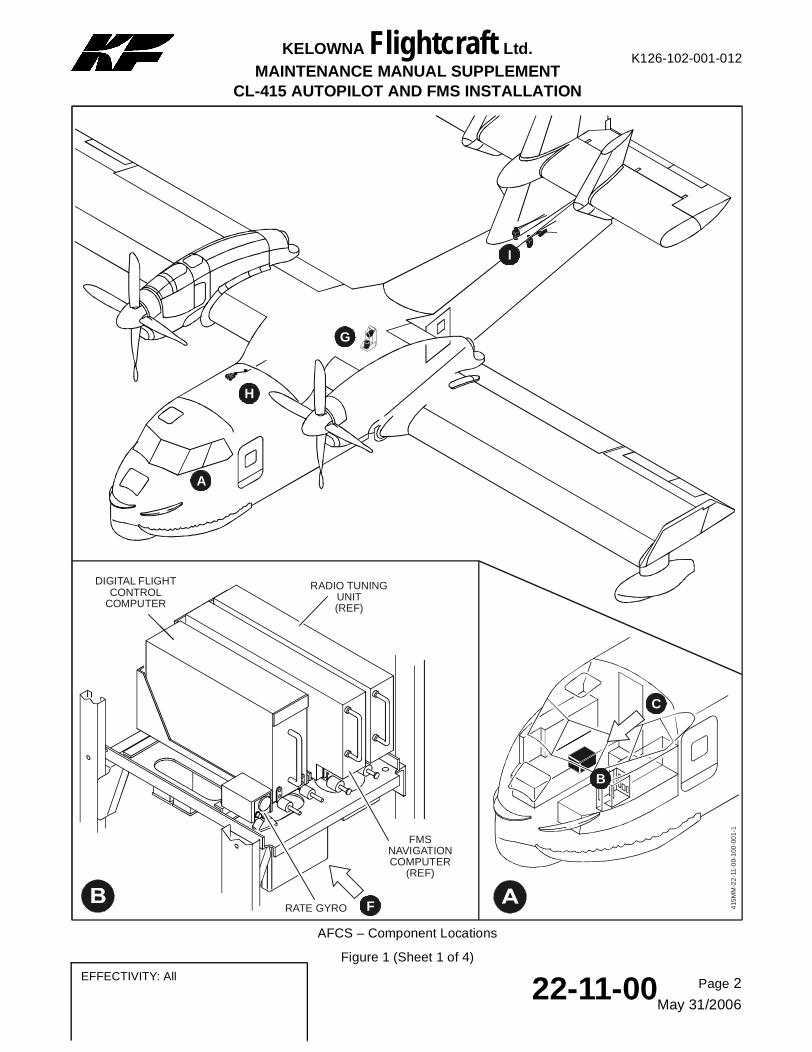
The automatic flight control system (AFCS) provides aircraft stabilization and automatic flight path control. The AFCS is integrated with existing aircraft systems and equipment but can be completely isolated from them. The AFCS has these major components:
– One digital flight control computer
– One autopilot controller
– One autopilot transfer switching Ledex
– One AFCS mode select panel
– One rate gyro
– Two scaling transformers, one for pitch and one for roll
– One normal accelerometer
– One lateral accelerometer
– One air data sensor (Refer to Chapter 34-18-00 of this Supplement)
– Two AFCS annunciator panels
– Two D/S-100 digital-to-analogue adapters
– One elevator servo
– One aileron servo
– One rudder servo
– Two touch-control-steering (TCS) switches
– Two autopilot disconnect (AP DISC) switches.
(1) Digital Flight Control Computer
The digital flight control computer (DFCC) processes data about the aircraft’s actual attitude compared to the desired attitude. The data is processed as a function of the selected flight mode to produce pitch, roll, and yaw outputs to the autopilot servos, and pitch and roll steering commands for the flight director. In addition to the modes selectable on the autopilot controller, the DFCC can produce heading, long-range navigation, and altitude-hold outputs to the flight director. The DFCC processes analogue inputs into digital data, and then converts the digital computations into analogue outputs.
The DFCC is installed on a mounting tray located on the autopilot equipment rack (FS 214, WL 144, BL 19R).
Page 1
May 31/200622-11-00 EFFECTIVITY: All
SAMPLE
Page 2
May 31/200622-11-00
EFFECTIVITY: All
K126-102-001-012KELOWNA Flightcraft Ltd.
MAINTENANCE MANUAL SUPPLEMENTCL-415 AUTOPILOT AND FMS INSTALLATION
C
B
H
A
I
DIGITAL FLIGHT CONTROL
COMPUTER
RADIO TUNING UNIT(REF)
RATE GYRO F
G
415
MM
-22
-11-
00-
100
-00
1-1
FMS NAVIGATION COMPUTER
(REF)
AFCS – Component Locations
Figure 1 (Sheet 1 of 4)

SAMPLE
Page 3
May 31/200622-11-00 EFFECTIVITY: All
K126-102-001-012KELOWNA Flightcraft Ltd.
MAINTENANCE MANUAL SUPPLEMENTCL-415 AUTOPILOT AND FMS INSTALLATION
D
AFCS MODE SELECTOR
FLIGHT MANAGEMENT SYSTEM CDU
(REF)
FLIGHT CONTROL PANEL(REF)
AUTOPILOT CONTROLLER
ON
STBY
HDG
LNAV
ALT
STBY
ON
ON
FUEL
DATA
TUNE
PREV
NEXT
PWRDIM
ENTER BACK +/-
NAV
DTO
FPL
VNAV
LIST
MENU
MSG
PERF
A B C D E F G
H I J K L M N
O P Q R S T U
V W X Y
1 2 3
4 5 6
7 8 9
0Z
DEPARTURE RW POS
ACTIVE FLIGHT PLANORIGIN SPD CMD
RW08R KPHX 250/ .75M038º 199NM
GUP 00 + 40 — / FL410
— / FL410040º 506NM
*LL05 01 + 41
ELEVATOREMERG
EMERGMAN
MODE
MANUAL
TRIM
RESETDISC
FAILOFF
HILO
RTC PRESSURE PRESSURE
MANUAL
TRIM TRIM
MANUAL
HILO
DISC
RESET
Q TEST
LEFT
RIGHT
RUDDER AILERONLEFT
RIGHT
MODE MODE
COUPLESOFTRIDE
TRI
M
1 2 ON
AP YD
TURNDESCEND
CLIMB
PITCH
DN
UP
AFCS ANNUNCIATOR
C
NOTE:PILOT PANEL SHOWN, COPILOT PANEL SIMILAR.
AIRSPEED INDICATOR
(REF)
ELECTRONIC ATTITUDE DIRECTOR
INDICATOR(REF)
ENCODER ALTIMETER
(REF)
FAILAPOFF
YDOFF
UP DN
TRIMAFCS
FMS ANNUNCIATOR
(REF)
E
E
D
415
MM
-22-
11-0
0-1
00
-00
1-2
AFCS – Component Locations
Figure 1 (Sheet 2 of 4)
SAMPLE
Page 4
May 31/200622-11-00
EFFECTIVITY: All
K126-102-001-012KELOWNA Flightcraft Ltd.
MAINTENANCE MANUAL SUPPLEMENTCL-415 AUTOPILOT AND FMS INSTALLATION
UP
NO. 1SCALING
TRANSFORMERNO. 2
SCALING TRANSFORMER
NO. 2DIGITAL-TO-ANALOGUE
CONVERTER
NO. 1DIGITAL-TO-ANALOGUE
CONVERTER
AFCSTRANSFER LEDEX
AURAL ALERTER(REF)
AFCS MAINTENANCE PANEL
FUEL FLOW CONVERTER
(REF)
UP
NORMAL ACCELEROMETER
LATERAL ACCELEROMETER
415M
M-2
2-11
-00
-10
0-0
01-3
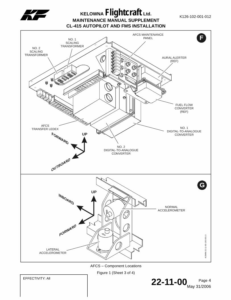
AFCS – Component Locations
Figure 1 (Sheet 3 of 4)
SAMPLE
Page 5
May 31/200622-11-00 EFFECTIVITY: All
K126-102-001-012KELOWNA Flightcraft Ltd.
MAINTENANCE MANUAL SUPPLEMENTCL-415 AUTOPILOT AND FMS INSTALLATION
H
I
UP
UP
AILERON SERVO
ELEVATOR SERVO
RUDDER SERVO
415
MM
-22-
11-0
0-1
00
-00
1-4
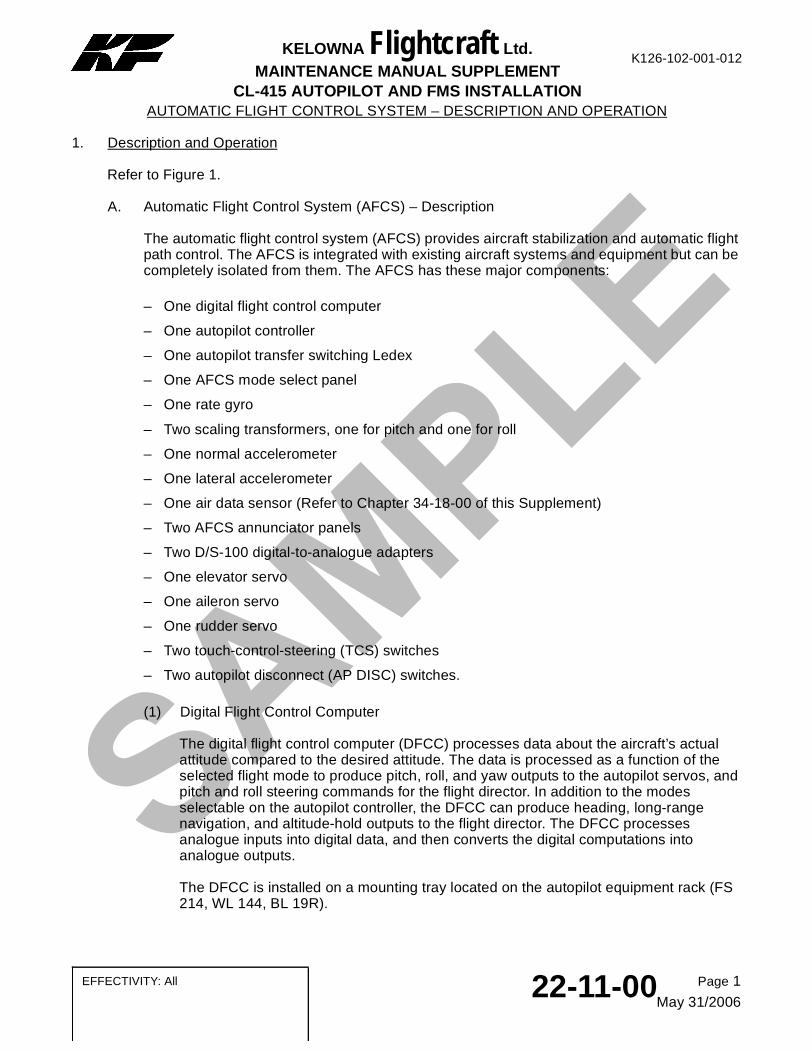
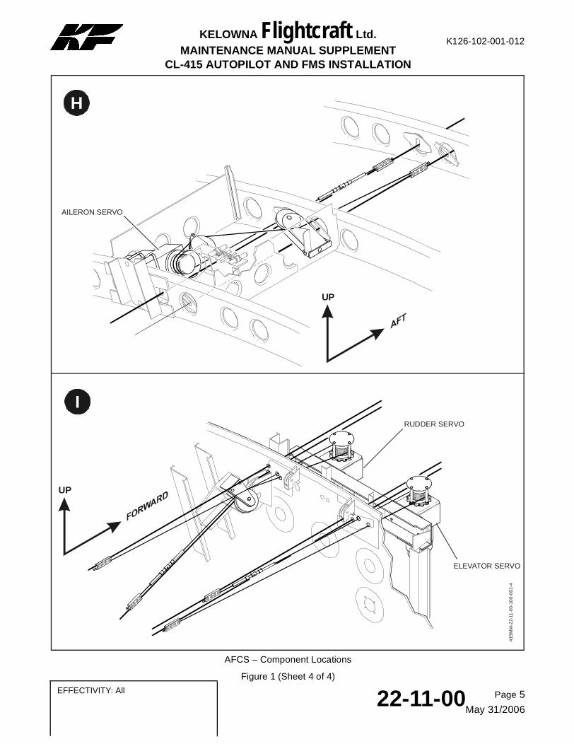
AFCS – Component Locations
Figure 1 (Sheet 4 of 4)
K126-102-001-012KELOWNA Flightcraft Ltd.
MAINTENANCE MANUAL SUPPLEMENT
SAMPLECL-415 AUTOPILOT AND FMS INSTALLATION
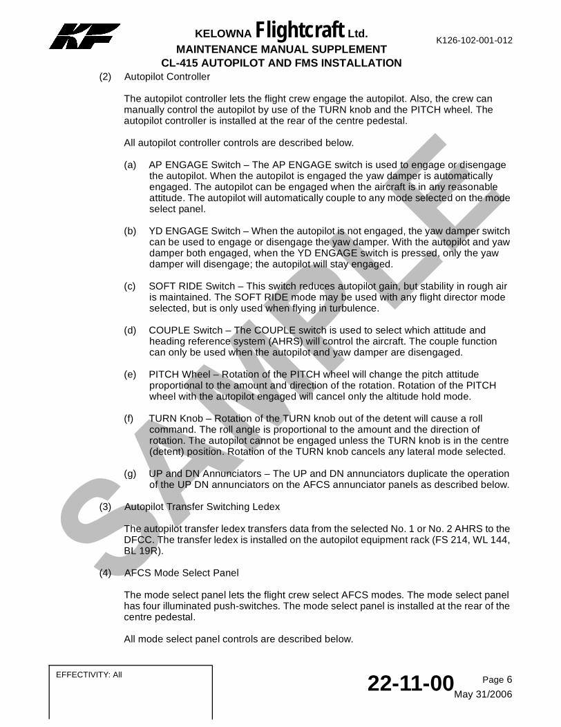
(2) Autopilot Controller
The autopilot controller lets the flight crew engage the autopilot. Also, the crew can manually control the autopilot by use of the TURN knob and the PITCH wheel. The autopilot controller is installed at the rear of the centre pedestal.
All autopilot controller controls are described below.
(a) AP ENGAGE Switch – The AP ENGAGE switch is used to engage or disengage the autopilot. When the autopilot is engaged the yaw damper is automatically engaged. The autopilot can be engaged when the aircraft is in any reasonable attitude. The autopilot will automatically couple to any mode selected on the mode select panel.
(b) YD ENGAGE Switch – When the autopilot is not engaged, the yaw damper switch can be used to engage or disengage the yaw damper. With the autopilot and yaw damper both engaged, when the YD ENGAGE switch is pressed, only the yaw damper will disengage; the autopilot will stay engaged.
(c) SOFT RIDE Switch – This switch reduces autopilot gain, but stability in rough air is maintained. The SOFT RIDE mode may be used with any flight director mode selected, but is only used when flying in turbulence.
(d) COUPLE Switch – The COUPLE switch is used to select which attitude and heading reference system (AHRS) will control the aircraft. The couple function can only be used when the autopilot and yaw damper are disengaged.
(e) PITCH Wheel – Rotation of the PITCH wheel will change the pitch attitude proportional to the amount and direction of the rotation. Rotation of the PITCH wheel with the autopilot engaged will cancel only the altitude hold mode.
(f) TURN Knob – Rotation of the TURN knob out of the detent will cause a roll command. The roll angle is proportional to the amount and the direction of rotation. The autopilot cannot be engaged unless the TURN knob is in the centre (detent) position. Rotation of the TURN knob cancels any lateral mode selected.
(g) UP and DN Annunciators – The UP and DN annunciators duplicate the operation of the UP DN annunciators on the AFCS annunciator panels as described below.
(3) Autopilot Transfer Switching Ledex
The autopilot transfer ledex transfers data from the selected No. 1 or No. 2 AHRS to the DFCC. The transfer ledex is installed on the autopilot equipment rack (FS 214, WL 144, BL 19R).
(4) AFCS Mode Select Panel
The mode select panel lets the flight crew select AFCS modes. The mode select panel has four illuminated push-switches. The mode select panel is installed at the rear of the centre pedestal.
All mode select panel controls are described below.
Page 6
May 31/200622-11-00
EFFECTIVITY: All
K126-102-001-012KELOWNA Flightcraft Ltd.
MAINTENANCE MANUAL SUPPLEMENT
SAMPLECL-415 AUTOPILOT AND FMS INSTALLATION
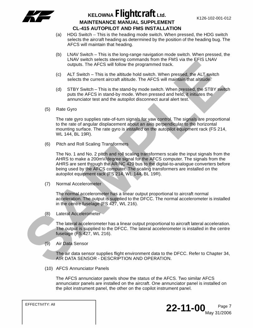
(a) HDG Switch – This is the heading mode switch. When pressed, the HDG switch selects the aircraft heading as determined by the position of the heading bug. The AFCS will maintain that heading.
(b) LNAV Switch – This is the long-range navigation mode switch. When pressed, the LNAV switch selects steering commands from the FMS via the EFIS LNAV outputs. The AFCS will follow the programmed track.
(c) ALT Switch – This is the altitude hold switch. When pressed, the ALT switch selects the current aircraft altitude. The AFCS will maintain that altitude.
(d) STBY Switch – This is the stand-by mode switch. When pressed, the STBY switch puts the AFCS in stand-by mode. When pressed and held, it initiates the annunciator test and the autopilot disconnect aural alert test.
(5) Rate Gyro
The rate gyro supplies rate-of-turn signals for yaw control. The signals are proportional to the rate of angular displacement about an axis perpendicular to the horizontal mounting surface. The rate gyro is installed on the autopilot equipment rack (FS 214, WL 144, BL 19R).
(6) Pitch and Roll Scaling Transformers
The No. 1 and No. 2 pitch and roll scaling transformers scale the input signals from the AHRS to make a 200mV/degree signal for the AFCS computer. The signals from the AHRS are sent through the ARINC 429 bus to the digital-to-analogue converters before being used by the AFCS computer. The scaling transformers are installed on the autopilot equipment rack (FS 214, WL 144, BL 19R).
(7) Normal Accelerometer
The normal accelerometer has a linear output proportional to aircraft normal acceleration. The output is supplied to the DFCC. The normal accelerometer is installed in the centre fuselage (FS 427, WL 216).
(8) Lateral Accelerometer
The lateral accelerometer has a linear output proportional to aircraft lateral acceleration. The output is supplied to the DFCC. The lateral accelerometer is installed in the centre fuselage (FS 427, WL 216).
(9) Air Data Sensor
The air data sensor supplies flight environment data to the DFCC. Refer to Chapter 34, AIR DATA SENSOR - DESCRIPTION AND OPERATION.
(10) AFCS Annunciator Panels
The AFCS annunciator panels show the status of the AFCS. Two similar AFCS annunciator panels are installed on the aircraft. One annunciator panel is installed on the pilot instrument panel, the other on the copilot instrument panel.
Page 7
May 31/200622-11-00 EFFECTIVITY: All
K126-102-001-012KELOWNA Flightcraft Ltd.
MAINTENANCE MANUAL SUPPLEMENT
SAMPLECL-415 AUTOPILOT AND FMS INSTALLATION
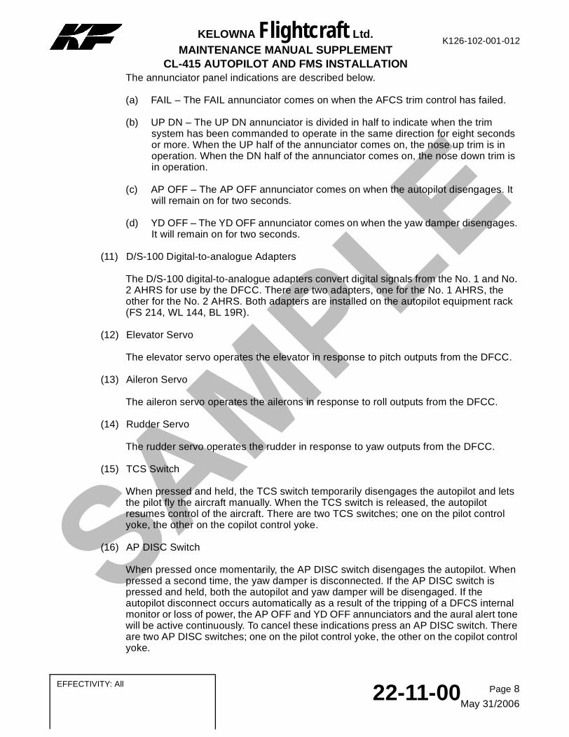
The annunciator panel indications are described below.
(a) FAIL – The FAIL annunciator comes on when the AFCS trim control has failed.
(b) UP DN – The UP DN annunciator is divided in half to indicate when the trim system has been commanded to operate in the same direction for eight seconds or more. When the UP half of the annunciator comes on, the nose up trim is in operation. When the DN half of the annunciator comes on, the nose down trim is in operation.
(c) AP OFF – The AP OFF annunciator comes on when the autopilot disengages. It will remain on for two seconds.
(d) YD OFF – The YD OFF annunciator comes on when the yaw damper disengages. It will remain on for two seconds.
(11) D/S-100 Digital-to-analogue Adapters
The D/S-100 digital-to-analogue adapters convert digital signals from the No. 1 and No. 2 AHRS for use by the DFCC. There are two adapters, one for the No. 1 AHRS, the other for the No. 2 AHRS. Both adapters are installed on the autopilot equipment rack (FS 214, WL 144, BL 19R).
(12) Elevator Servo
The elevator servo operates the elevator in response to pitch outputs from the DFCC.
(13) Aileron Servo
The aileron servo operates the ailerons in response to roll outputs from the DFCC.
(14) Rudder Servo
The rudder servo operates the rudder in response to yaw outputs from the DFCC.
(15) TCS Switch
When pressed and held, the TCS switch temporarily disengages the autopilot and lets the pilot fly the aircraft manually. When the TCS switch is released, the autopilot resumes control of the aircraft. There are two TCS switches; one on the pilot control yoke, the other on the copilot control yoke.
(16) AP DISC Switch
When pressed once momentarily, the AP DISC switch disengages the autopilot. When pressed a second time, the yaw damper is disconnected. If the AP DISC switch is pressed and held, both the autopilot and yaw damper will be disengaged. If the autopilot disconnect occurs automatically as a result of the tripping of a DFCS internal monitor or loss of power, the AP OFF and YD OFF annunciators and the aural alert tone will be active continuously. To cancel these indications press an AP DISC switch. There are two AP DISC switches; one on the pilot control yoke, the other on the copilot control yoke.
Page 8
May 31/200622-11-00
EFFECTIVITY: All
K126-102-001-012KELOWNA Flightcraft Ltd.
MAINTENANCE MANUAL SUPPLEMENT
SAMPLECL-415 AUTOPILOT AND FMS INSTALLATION
B. Automatic Flight Control System – Operation
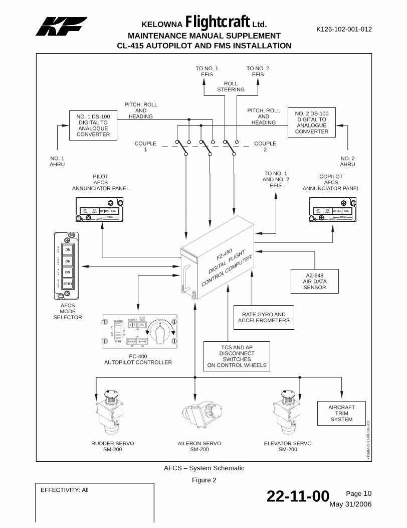
Refer to Figure 2.
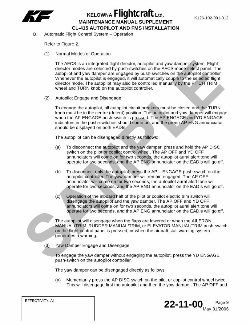
(1) Normal Modes of Operation
The AFCS is an integrated flight director, autopilot and yaw damper system. Flight director modes are selected by push-switches on the AFCS mode select panel. The autopilot and yaw damper are engaged by push-switches on the autopilot controller. Whenever the autopilot is engaged, it will automatically couple to the selected flight director mode. The autopilot may also be controlled manually by the PITCH TRIM wheel and TURN knob on the autopilot controller.
(2) Autopilot Engage and Disengage
To engage the autopilot, all autopilot circuit breakers must be closed and the TURN knob must be in the centre (detent) position. The autopilot and yaw damper will engage when the AP ENGAGE push-switch is pressed. The AP ENGAGE and YD ENGAGE indicators in the push-switches should come on, and the green AP ENG annunciator should be displayed on both EADIs.
The autopilot can be disengaged directly as follows:
(a) To disconnect the autopilot and the yaw damper, press and hold the AP DISC switch on the pilot or copilot control wheel. The AP OFF and YD OFF annunciators will come on for two seconds, the autopilot aural alert tone will operate for two seconds, and the AP ENG annunciator on the EADIs will go off.
(b) To disconnect only the autopilot, press the AP – ENGAGE push-switch on the autopilot controller. The yaw damper will remain engaged. The AP OFF annunciator will come on for two seconds, the autopilot aural alert tone will operate for two seconds, and the AP ENG annunciator on the EADIs will go off.
(c) Operation of the inboard half of the pilot or copilot electric trim switch will disengage the autopilot and the yaw damper. The AP OFF and YD OFF annunciators will come on for two seconds, the autopilot aural alert tone will operate for two seconds, and the AP ENG annunciator on the EADIs will go off.
The autopilot will disengage when the flaps are lowered or when the AILERON MANUAL/TRIM, RUDDER MANUAL/TRIM, or ELEVATOR MANUAL/TRIM push-switch on the flight control panel is pressed, or when the aircraft stall warning system generates a warning.
(3) Yaw Damper Engage and Disengage
To engage the yaw damper without engaging the autopilot, press the YD ENGAGE push-switch on the autopilot controller.
The yaw damper can be disengaged directly as follows:
(a) Momentarily press the AP DISC switch on the pilot or copilot control wheel twice. This will disengage first the autopilot and then the yaw damper. The AP OFF and
Page 9
May 31/200622-11-00 EFFECTIVITY: All
SAMPLE
Page 10
May 31/200622-11-00
EFFECTIVITY: All
K126-102-001-012KELOWNA Flightcraft Ltd.
MAINTENANCE MANUAL SUPPLEMENTCL-415 AUTOPILOT AND FMS INSTALLATION
NO. 1 DS-100DIGITAL TO ANALOGUE
CONVERTER
NO. 2 DS-100DIGITAL TO ANALOGUE
CONVERTER
FAILAPOFF
YDOFF
UP DN
TRIMAFCS
ON
STBY
HDG
LNAV
ALT
STBY
ON
ON
FAILAPOFF
YDOFF UP DN
TRIMAFCS
AZ-648AIR DATA SENSOR
COUPLESOFTRIDE
TRI
M
1 2 ON
AP YD
TURNDESCEND
CLIMB
PITCH
DN
UP
PITCH, ROLL AND
HEADINGPITCH, ROLL
AND HEADING
NO. 1 AHRU
NO. 2 AHRU
TO NO. 1 EFIS
TO NO. 2 EFIS
ROLLSTEERING
COUPLE1
COUPLE2
RATE GYRO ANDACCELEROMETERS
TO NO. 1 AND NO. 2
EFIS
AIRCRAFTTRIM
SYSTEM
RUDDER SERVOSM-200
AILERON SERVOSM-200
ELEVATOR SERVOSM-200
PC-400AUTOPILOT CONTROLLER
AFCSMODE
SELECTOR
PILOTAFCS
ANNUNCIATOR PANEL
COPILOTAFCS
ANNUNCIATOR PANEL
TCS AND AP DISCONNECT
SWITCHESON CONTROL WHEELS
415
MM
-22
-11-
00-
100
-00
2
AFCS – System Schematic
Figure 2
K126-102-001-012KELOWNA Flightcraft Ltd.
MAINTENANCE MANUAL SUPPLEMENT
SAMPLECL-415 AUTOPILOT AND FMS INSTALLATION
YD OFF annunciators will come on for two seconds, the autopilot aural alert tone will operate for two seconds, and the AP ENG annunciator on the EADI will go off.
(b) Press the YD ENGAGE push-switch on the autopilot controller. The YD OFF annunciator will come on for two seconds and the autopilot aural alert tone will operate for two seconds.
(4) Basic Attitude and Heading Hold
When the autopilot is engaged with no flight director modes selected, pitch attitude and heading are held. If roll attitude is less than 6 degrees, the autopilot will command wings level, then heading hold.
When the TURN knob on the autopilot controller is rotated, the autopilot will command a roll attitude that is proportional to the amount of TURN knob rotation. When the TURN knob is rotated out of the detent position with the autopilot engaged, all the lateral flight director modes will be cancelled.
When the PITCH TRIM wheel on the autopilot controller is rotated, the autopilot will command a pitch attitude change proportional to the amount of pitch wheel movement and the rate of pitch wheel movement. When the PITCH TRIM wheel is rotated with the autopilot engaged, altitude hold (ALT) will be cancelled.
The SOFT RIDE push-switch on the autopilot controller reduces the autopilot gain. The SOFT RIDE mode may be used with any flight director mode selected, but is only used when flying in turbulence. SOFT RIDE is automatically cancelled if the autopilot is disengaged.
(5) Flight Director Coupling
When engaged, the autopilot automatically couples to any flight director mode that is selected.
(6) Touch Control Steering (TCS) With Autopilot Coupled to Flight Director
The TCS allows the pilot to override autopilot modes (by disengaging the pitch and roll servos) in the two ways that follow.
(a) In attitude or altitude hold (ALT), with a TCS switch pressed and held, the TCS synchronizes the hold references. When the TCS switch is released, the new reference is held.
(b) In HDG or LNAV mode, with a TCS switch pressed and held, the TCS allows corrective or supervisory override without mode disengagement. When the TCS switch is released, the autopilot will recouple to the selected mode.
(7) Heading Select Mode (HDG)
The heading select mode is used to turn toward and to maintain a magnetic heading. In the HDG mode, the flight control computer provides inputs to the flight director to command a turn to the heading indicated by the heading bug on the EHSI.
Page 11
May 31/200622-11-00 EFFECTIVITY: All
K126-102-001-012KELOWNA Flightcraft Ltd.
MAINTENANCE MANUAL SUPPLEMENT
SAMPLECL-415 AUTOPILOT AND FMS INSTALLATION
To select the HDG mode, rotate the pilot HDG knob to set the EHSI heading bug to the desired heading, then press the HDG push-switch on the AFCS mode selector. The mode is annunciated as HDG in green on the top left side of the EADI.
NOTE: When the autopilot controller couple switch is set to 1, the pilot EFIS is used to set the heading bug. When the couple switch is set to 2, the copilot EFIS is used to set the heading bug.
NOTE:The heading select signal is gain programmed as a function of airspeed. The bank angle limit is 25 degrees in the heading select mode.
To cancel the HDG mode, press the HDG, LNAV or STBY push-switch on the AFCS mode selector, or select HDG REV to an invalid HDG source. Also, if the TURN knob is rotated when the autopilot is engaged, the HDG mode will be cancelled.
(8) FMS Steering Mode (LNAV)
The FMS steering mode uses the FMS as the navigation source. The LNAV mode can be flown when a valid FMS flight plan is entered. To select the LNAV mode press the FMS push-switch on the EFIS display controller, then press the LNAV push-switch on the AFCS mode selector. LNAV, in green, will be annunciated in the upper left portion of the EADI. The flight director and autopilot will use the FMS-supplied steering command via the EFIS LNAV outputs to capture and track the FMS course.
NOTE:There is no FMS LNAV ARM mode.The HDG mode is cancelled immediately on selection of LNAV.
To cancel LNAV mode, press the LNAV, HDG or STBY push-switch on the AFCS mode selector, select an alternate NAV source, or select HDG REV to an invalid HDG source.
(9) Pitch Attitude Hold Mode
The pitch attitude hold mode is the basic vertical flight director mode. It is activated when a flight director lateral (roll) mode is selected without an accompanying vertical (pitch) mode. There is no permanent annunciation for pitch hold mode except the basic AP ENG annunciation whenever the autopilot is engaged. The pitch command on the EADI provides the pilot with a pitch reference corresponding to the pitch attitude existing at the moment the lateral mode was selected. This pitch reference can be changed by using TCS to maneuver to a new altitude and then releasing the TCS switch.
When the autopilot is engaged, the reference pitch attitude can be changed as function of the PITCH TRIM wheel on the autopilot controller. Pitch attitude hold is superseded by the selection of ALT mode.
(10) Altitude Hold (ALT) Mode
The altitude hold mode is a vertical axis flight director mode used to maintain a barometric altitude reference. The altitude reference is supplied from the air data sensor. The vertical command for altitude hold is displayed on the flight director pitch command cue on the EADI.
Page 12
May 31/200622-11-00
EFFECTIVITY: All
K126-102-001-012KELOWNA Flightcraft Ltd.
MAINTENANCE MANUAL SUPPLEMENT
SAMPLECL-415 AUTOPILOT AND FMS INSTALLATION
To select altitude hold press the ALT push-switch on the AFCS mode selector. At this time, the ALT annunciator is displayed in green on the EADI and the AFCS mode select panel ALT indicator comes on. The vertical axis of the flight director will maintain the aircraft pressure altitude at the time of mode selection. The reference altitude may be changed by using TCS to maneuver to a new altitude and then releasing the TCS switch.
NOTE:There is no barometric correction to the air data sensor. A change in altimeter setting at the pilot or copilot station will not be reflected in the autopilot reference altitude.
To cancel the ALT hold mode, press the ALT or STBY push-switch on the AFCS mode selector, or if the autopilot is engaged, rotate the PITCH TRIM wheel on the autopilot controller.
(11) BITE Test
When power is first applied to the AFCS, the DFCC does a BITE-test of the system. If all parts of the system are serviceable, the system will operate normally. If there are any faults in the system, the STBY push-switch indicator on the AFCS mode select panel will flash continuously.
(12) Self-test
To do a self-test of the autopilot annunciators, press and hold the STBY push-switch on the AFCS mode select panel. All autopilot annunciators will come on for 5 seconds, after which all annunciators will go off and the autopilot disconnect tone will sound.
Page 13
May 31/200622-11-00 EFFECTIVITY: All

SAMPLE