Embed Size (px)
Citation preview
DEKRA Certification B.V.
?R. SchullerCertification Manager Page 1/3
©Integral publication of this certificate and adjoining reports is allowed. This Certificate may only be reproducedin its entirety and without any change.
DEKRA Certification B.V. Meander 1051, 6825 MJ Arnhem P.O. Box 5185, 6802 ED Arnhem The NetherlandsT +31 88 96 83000 F +31 88 96 83100 www.dekra-certification.com Registered Arnhem 09085396
CERTIFICATE(1) EC-Type Examination(2) Equipment and protective systems intended for use in
potentially explosive atmospheres - Directive 94/9/EC
(3) EC-Type Examination Certificate Number: KEMA 02ATEX1090 X Issue Number: 7
(4) Equipment: Two Wire Proximity Sensors Type ...-….-.Y1.-….. / ….
(5) Manufacturer: Hans Turck GmbH & Co. KG
(6) Address: Witzlebenstrasse 7, 45472 Mülheim an der Ruhr, Germany
(7) This equipment and any acceptable variation thereto is specified in the schedule to this certificate and thedocuments therein referred to.
(8) DEKRA Certification B.V., notified body number 0344 in accordance with Article 9 of the Council Directive 94/9/ECof 23 March 1994, certifies that this equipment has been found to comply with the Essential Health and SafetyRequirements relating to the design and construction of equipment and protective systems intended for use inpotentially explosive atmospheres given in Annex II to the directive.
The examination and test results are recorded in confidential test report number NL/KEM/ExTR06.0032/04.
(9) Compliance with the Essential Health and Safety Requirements has been assured by compliance with:
EN 60079-0 : 2012 + A11 EN 60079-11 : 2012
(10) If the sign ”X” is placed after the certificate number, it indicates that the equipment is subject to special conditionsfor safe use specified in the schedule to this certificate.
(11) This EC-Type Examination Certificate relates only to the design, examination and tests of the specified equipmentaccording to the Directive 94/9/EC. Further requirements of the directive apply to the manufacturing process andsupply of this equipment. These are not covered by this certificate.
(12) The marking of the equipment shall include the following:
II 1G Ex ia IIC T4 … T6 Ga orII 2G Ex ia IIC T4 … T6 Gb and / orII 1D Ex ia IIIC T95 °C or T115 °C Da
This certificate is issued on 8 April 2016 and, as far as applicable, shall be revised before the date of cessation of presumption of conformity of (one of) the standards mentioned above as communicated in the Official Journal of the European Union.
(13) SCHEDULE
(14) to EC-Type Examination Certificate KEMA 02ATEX1090 X Issue No. 7
Page 2/3
Form 100Version 5 (2013-07)
(15) Description
Two Wire Proximity Sensors Type ...-….-.Y1.-….. / …. are used for initiation of signalling or switching functions on a preset distance value being reached.The model code of the range of Two Wire Proximity Sensors Type ...-….-.Y1.-….. / …. is characterised as shown in table 1 of annex 1
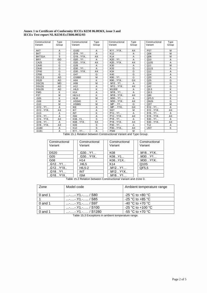
The range of Two Wire Proximity Sensors Type ...-….-.Y1.-….. / …. consists of various constructional variants classified into ten Type Groups.The identification of the applicable Type Group is related to the Constructional Variant and can be determined from table 15.1 of annex 1.
Category II 1 G only applies to the Constructional Variants shown in table 15.2 of annex 1.
Ambient temperature range -25 °C to +70 °C for all models, with the exceptions shown in table 15.3 of annex 1.
The temperature class of the different Sensor models, depending on ambient temperature, Ii and Pi, can be determined from tables 15.4, 15.6, 15.8, 15.10 and 15.12 (see annex 1), using table 15.1 in annex 1 for the type group designation.
For potentially explosive atmospheres caused by the presence of combustible dust, the maximum surface temperature for the Two Wire Proximity Sensors in Type Groups AX and GX is T115 °C and for all other Two Wire Proximity Sensors is T95 °C at a maximum ambient temperature of 70 °C.
Electrical data
See annex 1.
Installation instructions
The instructions provided with the equipment shall be followed in detail to assure safe operation.
(16) Test Report
No. NL/KEM/ExTR06.0032/04.
(17) Special conditions for safe use
For the ambient temperature range, see (15).
For use in an area requiring equipment with EPL Ga: If part of the enclosure is made of plastic and the projected surface area is greater than 4 cm² for apparatus of group IIC, 25 cm² for apparatus of group IIB or 50 cm² for apparatus of group IIA, the sensor is accompanied with a warning to avoid static charging. In this case, precautions have to be taken that the risk of electrostatic charging of the enclosure is excluded.
(13) SCHEDULE
(14) to EC-Type Examination Certificate KEMA 02ATEX1090 X Issue No. 7
Page 3/3
Form 100Version 5 (2013-07)
For use in an area requiring equipment with EPL Gb, for group IIC:If part of the enclosure is made of plastic and the projected surface area is greater than 20 cm², the sensor is accompanied with a warning to avoid static charging. In this case precautions have to be taken that the risk of electrostatic charging of the enclosure is excluded.
The Two Wire Proximity Sensors used in a potentially explosive atmospheres caused by the presence of combustible dust, must be mounted in such a way that they are protected against impact.
(18) Essential Health and Safety Requirements
Covered by the standards listed at (9).
(19) Test documentation
As listed in Test Report No. NL/KEM/ExTR06.0032/04.
Annex 1 to Certificate of Conformity IECEx KEM 06.0036X, issue 4
Annex 1 to IECEx Test report NL/KEM/ExTR06.0032/04
Annex 1 to KEMA 02ATEX1090 X, issue 7
Page 1 of 5 Form 124
Version 2 (2013-07)
DEKRA Certification B.V. Meander 1051, 6825 MJ Arnhem P.O. Box 5185, 6802 ED Arnhem The Netherlands
T +31 88 9683000 F +31 88 9683100 www.dekra-certification.com Registered Arnhem 09085396
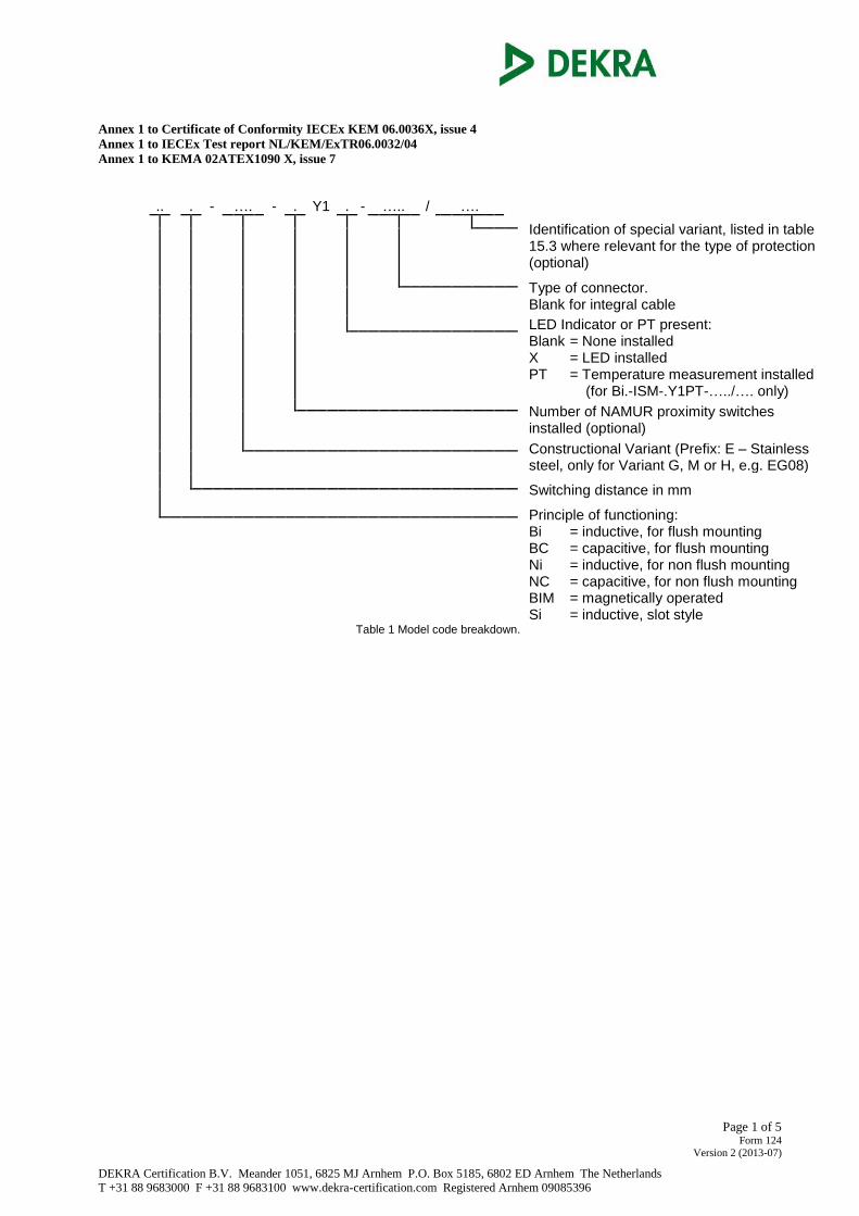
Type .. . - …. - . Y1 . - ….. / ….
Identification of special variant, listed in table 15.3 where relevant for the type of protection (optional)
Type of connector. Blank for integral cable
LED Indicator or PT present: Blank = None installed X = LED installed PT = Temperature measurement installed (for Bi.-ISM-.Y1PT-…../…. only)
Number of NAMUR proximity switches installed (optional)
Constructional Variant (Prefix: E – Stainless steel, only for Variant G, M or H, e.g. EG08)
Switching distance in mm
Principle of functioning: Bi = inductive, for flush mounting BC = capacitive, for flush mounting Ni = inductive, for non flush mounting NC = capacitive, for non flush mounting BIM = magnetically operated Si = inductive, slot style
Table 1 Model code breakdown.
Annex 1 to Certificate of Conformity IECEx KEM 06.0036X, issue 3 and
IECEx Test report NL/KEM/ExTR06.0032/03
Page 2 of 5
Constructional Variant
Type Group
Constructional Variant
Type Group
Constructional Variant
Type Group
Constructional Variant
Type Group
AKT A .G182 A K11…Y1X.. AX PST M
BKT S .G19…Y1… A K12 A Q06 M
BKT31A S .G19…Y1X.. AX K14 A Q08 M
BRY GD .G20…Y1… A K20…Y1… A Q10 A
CA25 G .G20…Y1X.. AX K20…Y1X.. AX Q10S A
CA40 G .G28 A K30 A Q11 M
CK40 G .G30…Y1… A K33 G Q11S A
CP40 G .G30…Y1X.. AX K34 G Q12 A
CP80 G .G47 G K40 G Q14 A
DS13,5 AD .GS880 M K90…Y1… G Q20 A
DS20 AD .H04 K K90…Y1X.. GX Q25 G
DSC26 MD .H08 M .M12…Y1… A Q30 G
DSU26 AD .H12 A .M12…Y1X.. AX Q42 G
DSU35 AD .H6,5 K M12EE A Q5.5 K
FMG K H14 A .M18…Y1… A Q6.5 K
FST M H6,5-2 K .M18…Y1X.. AX Q80 G
.G05 K HLM M .M30…Y1… A QF5,5 K
.G08 M .HS540 K .M30…Y1X.. AX QN26 G
.G10 M .HS865 M .MP …Y1… G QST M
.G12…Y1… A IKE A .MP …Y1X.. GX S12…Y1… A
.G12…Y1X.. AX IKT A NST M S12…Y1X.. AX
.G13 A INT K P12…Y1… A S18…Y1… A
.G14…Y1… A ISM A P12…Y1X.. AX S18…Y1X.. AX
.G14…Y1X.. AX K08...Y1... S P18…Y1… A S30…Y1… A
.G18…Y1… A K08…Y1X.. SX P18…Y1X.. AX S30…Y1X.. AX
.G18…Y1X.. AX K09 S P30…Y1… A T12 A
.G180 A K10 S P30…Y1X.. AX UNT K
.G181 A K11…Y1… A PSM M
Table 15.1 Relation between Constructional Variant and Type Group.
Constructional Variant
Constructional Variant
Constructional Variant
Constructional Variant
DS20 .G30…Y1… K08 .M18…Y1X..
G05 .G30…Y1X.. K08...Y1... .M30…Y1…
G08 H14 K08...Y1X.. .M30…Y1X..
.G12…Y1… .H6,5 K14 Q10S
.G12…Y1X.. H6,5-2 .M12…Y1… QF5,5
.G18…Y1… INT .M12…Y1X..
.G18…Y1X.. ISM .M18…Y1… Table 15.2 Relation between Constructional Variant and Zone 0.
Zone
Model code
Ambient temperature range
0 and 1 ...-….-.Y1.-….. / S80 -25 °C to +80 °C
1 ...-….-.Y1.-….. / S85 -25 °C to +85 °C
0 and 1 ...-….-.Y1.-….. / S97 -40 °C to +70 °C
1 ...-….-.Y1.-….. / S100 -25 °C to +100 °C
0 and 1 ...-….-.Y1.-….. / S1280 -55 °C to +70 °C Table 15.3 Exceptions in ambient temperature range.
Annex 1 to Certificate of Conformity IECEx KEM 06.0036X, issue 3 and
IECEx Test report NL/KEM/ExTR06.0032/03
Page 3 of 5
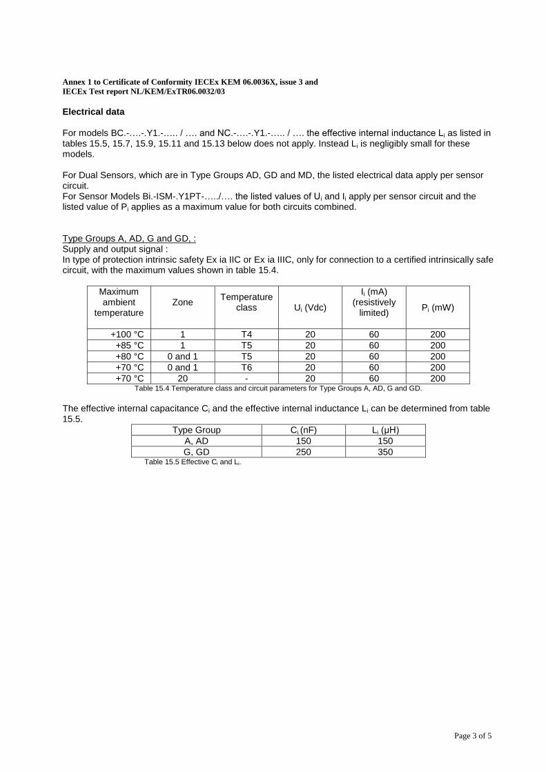
Electrical data For models BC.-….-.Y1.-….. / …. and NC.-….-.Y1.-….. / …. the effective internal inductance Li as listed in tables 15.5, 15.7, 15.9, 15.11 and 15.13 below does not apply. Instead Li is negligibly small for these models. For Dual Sensors, which are in Type Groups AD, GD and MD, the listed electrical data apply per sensor circuit. For Sensor Models Bi.-ISM-.Y1PT-…../…. the listed values of Ui and Ii apply per sensor circuit and the listed value of Pi applies as a maximum value for both circuits combined. Type Groups A, AD, G and GD, : Supply and output signal : In type of protection intrinsic safety Ex ia IIC or Ex ia IIIC, only for connection to a certified intrinsically safe circuit, with the maximum values shown in table 15.4.
Maximum ambient
temperature
Zone
Temperature class
Ui (Vdc)
Ii (mA) (resistively
limited)
Pi (mW)
+100 °C 1 T4 20 60 200
+85 °C 1 T5 20 60 200
+80 °C 0 and 1 T5 20 60 200
+70 °C 0 and 1 T6 20 60 200
+70 °C 20 - 20 60 200 Table 15.4 Temperature class and circuit parameters for Type Groups A, AD, G and GD.
The effective internal capacitance Ci and the effective internal inductance Li can be determined from table 15.5.
Type Group Ci (nF) Li (μH)
A, AD 150 150
G, GD 250 350 Table 15.5 Effective Ci and Li.
Annex 1 to Certificate of Conformity IECEx KEM 06.0036X, issue 3 and
IECEx Test report NL/KEM/ExTR06.0032/03
Page 4 of 5
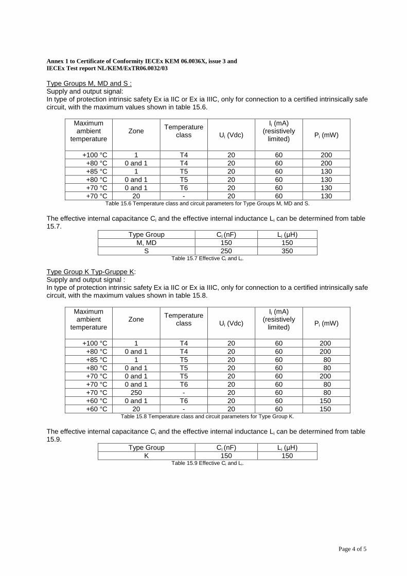
Type Groups M, MD and S : Supply and output signal: In type of protection intrinsic safety Ex ia IIC or Ex ia IIIC, only for connection to a certified intrinsically safe circuit, with the maximum values shown in table 15.6.
Maximum ambient
temperature
Zone
Temperature class
Ui (Vdc)
Ii (mA) (resistively
limited)
Pi (mW)
+100 °C 1 T4 20 60 200
+80 °C 0 and 1 T4 20 60 200
+85 °C 1 T5 20 60 130
+80 °C 0 and 1 T5 20 60 130
+70 °C 0 and 1 T6 20 60 130
+70 °C 20 - 20 60 130 Table 15.6 Temperature class and circuit parameters for Type Groups M, MD and S.
The effective internal capacitance Ci and the effective internal inductance Li can be determined from table 15.7.
Type Group Ci (nF) Li (μH)
M, MD 150 150
S 250 350 Table 15.7 Effective Ci and Li.
Type Group K Typ-Gruppe K: Supply and output signal : In type of protection intrinsic safety Ex ia IIC or Ex ia IIIC, only for connection to a certified intrinsically safe circuit, with the maximum values shown in table 15.8.
Maximum ambient
temperature
Zone
Temperature class
Ui (Vdc)
Ii (mA) (resistively
limited)
Pi (mW)
+100 °C 1 T4 20 60 200
+80 °C 0 and 1 T4 20 60 200
+85 °C 1 T5 20 60 80
+80 °C 0 and 1 T5 20 60 80
+70 °C 0 and 1 T5 20 60 200
+70 °C 0 and 1 T6 20 60 80
+70 °C 250 - 20 60 80
+60 °C 0 and 1 T6 20 60 150
+60 °C 20 - 20 60 150 Table 15.8 Temperature class and circuit parameters for Type Group K.
The effective internal capacitance Ci and the effective internal inductance Li can be determined from table 15.9.
Type Group Ci (nF) Li (μH)
K 150 150 Table 15.9 Effective Ci and Li.
Annex 1 to Certificate of Conformity IECEx KEM 06.0036X, issue 3 and
IECEx Test report NL/KEM/ExTR06.0032/03
Page 5 of 5
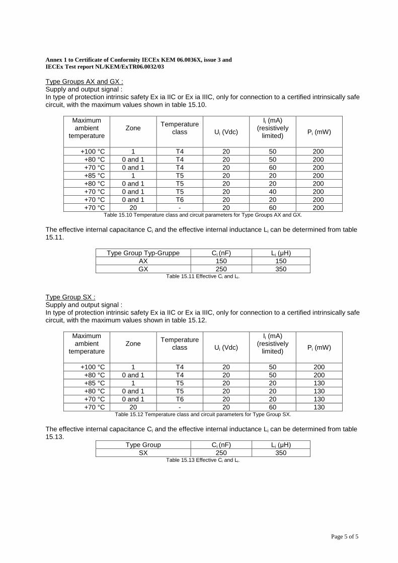
Type Groups AX and GX : Supply and output signal : In type of protection intrinsic safety Ex ia IIC or Ex ia IIIC, only for connection to a certified intrinsically safe circuit, with the maximum values shown in table 15.10.
Maximum ambient
temperature
Zone
Temperature class
Ui (Vdc)
Ii (mA) (resistively
limited)
Pi (mW)
+100 °C 1 T4 20 50 200
+80 °C 0 and 1 T4 20 50 200
+70 °C 0 and 1 T4 20 60 200
+85 °C 1 T5 20 20 200
+80 °C 0 and 1 T5 20 20 200
+70 °C 0 and 1 T5 20 40 200
+70 °C 0 and 1 T6 20 20 200
+70 °C 20 - 20 60 200 Table 15.10 Temperature class and circuit parameters for Type Groups AX and GX.
The effective internal capacitance Ci and the effective internal inductance Li can be determined from table 15.11.
Type Group Typ-Gruppe Ci (nF) Li (μH)
AX 150 150
GX 250 350 Table 15.11 Effective Ci and Li.
Type Group SX : Supply and output signal : In type of protection intrinsic safety Ex ia IIC or Ex ia IIIC, only for connection to a certified intrinsically safe circuit, with the maximum values shown in table 15.12.
Maximum ambient
temperature
Zone
Temperature class
Ui (Vdc)
Ii (mA) (resistively
limited)
Pi (mW)
+100 °C 1 T4 20 50 200
+80 °C 0 and 1 T4 20 50 200
+85 °C 1 T5 20 20 130
+80 °C 0 and 1 T5 20 20 130
+70 °C 0 and 1 T6 20 20 130
+70 °C 20 - 20 60 130 Table 15.12 Temperature class and circuit parameters for Type Group SX.
The effective internal capacitance Ci and the effective internal inductance Li can be determined from table 15.13.
Type Group Ci (nF) Li (μH)
SX 250 350 Table 15.13 Effective Ci and Li.


![A wake up-call_-_what_can_and_does_go_wrong_with_your_401(k)_pl[1]](https://img.pdfslide.net/doc/110x75/55b6054abb61ebf5438b460c/a-wake-up-call-whatcananddoesgowrongwithyour401kpl1.jpg)