Embed Size (px)
Citation preview

Operating manual • English
Käyttöohje • Suomi
Bruksanvisning • Svenska
Bruksanvisning • Norsk
Brugsanvisning • Dansk
Gebrauchsanweisung • Deutsch
Gebruiksaanwijzing • Nederlands
Manuel d’utilisation • Français
Manual de instrucciones • Español
Instrukcja obsługi • Polski
Инструкции по эксплуатации • По-русски
EN
FI
SV
NO
DA
DE
NL
FR
ES
PL
RU
Kempomat 2500, 3200, 4200

Operating manualenglish
Kem
pom
at 2
500,
320
0, 4
200
/ © K
empp
i Oy
/ 094
6
EN
COntents
1. preFaCe ......................................................................................31.1 General .................................................................................................................................................................31.2 Product introduction .................................................................................................................................31.3 General Safety Instructions ...................................................................................................................3
2. installatiOn OF the pOwer sOurCe ..................................62.1 Siting the machine ......................................................................................................................................62.2 Connection to the mains supply .......................................................................................................62.3 Mounting of the mains cable ..............................................................................................................62.4 Welding and return current cables ..................................................................................................7
3. use OF wireFeeder ..................................................................83.1 Parts of wire feed mechanism .............................................................................................................83.2 Installation of the wire feed system .............................................................................................103.3 Installation of wire feed ........................................................................................................................103.4 Mounting of MIG welding gun ........................................................................................................113.5 Mounting and locking of wire reel ...............................................................................................113.6 Automatic wire feed to gun ...............................................................................................................123.7 Adjustment of tightness of wire reel brake ............................................................................123.8 Shielding gas ................................................................................................................................................13
4. OperatiOn and use OF pOwer sOurCe ............................ 144.1 Kempomat panels .....................................................................................................................................144.2 Wire feed panel ...........................................................................................................................................154.3 Wire feeder unit ..........................................................................................................................................154.4 Main switches and pilot lamps ........................................................................................................164.5 Adjustment for arc roughness .........................................................................................................174.6 Operation of cooling fan ......................................................................................................................17
5. COntrOl panels and adjustments ................................ 175.1 Wire feed speed potentiometer .....................................................................................................175.2 Burn back time ............................................................................................................................................175.3 KMW timer functions ..............................................................................................................................18
6. aCCessOries ............................................................................ 186.1 KMW sync ........................................................................................................................................................196.2 Installation and mounting of KMW sync ..................................................................................19
7. OperatiOn disturbanCes ................................................... 20
8. regular maintenanCe OF the equipment .................... 208.1 Cables .................................................................................................................................................................208.2 Power source ................................................................................................................................................208.3 Disposal of the machine .......................................................................................................................21
9. Ordering numbers .............................................................. 21
10. teChniCal data ..................................................................... 22
11. warrantY pOliCY .................................................................. 24
2
Kem
pom
at 2
500,
320
0, 4
200
/ © K
empp
i Oy
/ 094
6
EN
1. preFaCe
1.1 generalCongratulations on choosing the Kempomat™ equipment. Used correctly, Kemppi products can significantly increase the productivity of your welding, and provide years of economical service. This operating manual contains important information on the use, maintenance and safety of your Kemppi product. The technical specifications of the equipment can be found at the end of the manual. Please read the manual carefully before using the equipment for the first time. For your own safety and that of your working environment, pay particular attention to the safety instructions in the manual.For more information on Kemppi products, contact Kemppi Oy, consult an authorised Kemppi dealer, or visit the Kemppi web site at www.kemppi.com.The specifications presented in this manual are subject to change without prior notice.
important notesItems in the manual that require particular attention in order to minimise damage and personal harm are indicated with the ’NOTE!’ notation. Read these sections carefully and follow their instructions.
1.2 prOduCt intrOduCtiOnThe power sources Kempomat 3200 and 4200 are compact MIG welding machines, designed for heavy industrial use. Kempomat 2500 is compact MIG welding machine, designed for repair shops and light and heavy industrial use.
power sourceSupply voltage of the Kempomat 2500 power source is 3~ 230 V/400 V. Supply voltage of the Kempomat 3200 power source is 3~ 230 V/400 V. Welding voltage adjustment is in 10-steps. Adjustment for voltage of power source is in 40-steps.In Kempomat 4200 product range there are different units for mains voltages 3~ 230 and 400 V. The welding voltage adjustment for 230 V power source is made in 32 steps, 400V power source in 56-steps. The Volt/Ampere metering unit MSD 1 (available as accessory) displays voltage or welding current.
wire feeder unitThe wire feeder unit is a fixed unit in the equipment for air-cooled guns. Kempomat 2500 is equipped with 2 wheel wire drive mechanism, Kempomat 3200 and 4200 are equipped with 4 wheel wire drive mechanism. Accessory unit KMW sync is needed for connection and use of push-pull guns.
1.3 general saFetY instruCtiOnsKemppi welding equipments conform to international safety standards. Safety is an important issue in equipment design and manufacturing. Therefore, Kemppi welding solutions are unparalleled in safety. There are, however, always certain hazards involved in using welding equipment. Therefore, to ensure your personal safety and the safety of your working environment, carefully read the safety instructions below and respect them.
use of personal protective equipment• The arc and its reflecting radiation damage unprotected eyes. Shield your eyes and
face appropriately before you start welding or observe welding. As the welding current increases, the welding face screen lens darkness should also increase.
• Arc radiation and spatters burn unprotected skin. Always wear protective gloves, clothing and footwear when welding.
• Always wear hearing protection if the ambient noise level exceeds the allowable limit (e.g., 85 dB).
3
Kem
pom
at 2
500,
320
0, 4
200
/ © K
empp
i Oy
/ 094
6
EN
general operating safety• Exercise caution when handling parts heated during welding. For example, the tip of
the welding torch or gun, and the end of the welding rod and the work piece. The temperature of items burn unprotected skin.
• Never wear any welding device on the shoulder during welding and never suspend it by the carrying strap during welding.
• Do not expose the machine to high temperatures, as this may cause damage.• Keep intermediate and earth return cables as close to each other as possible throughout
their length. Straighten any loops in the cables as this limits inductive effects on welding performance. This also minimizes your exposure to harmful magnetic fields, which may, for example, interfere with a pacemaker.
• Do not wrap the welding cables around your body.• In environments classified as dangerous, only use S-marked welding equipments with
a safe idle voltage level. These work environments include, for example, humid, hot or small spaces, where the user may be directly exposed to the surrounding conductive materials.
spatter and fire safety• Welding is always classified as hot work, so pay particular attention to the fire safety
regulations during welding and after it.• Remember that fire can break out from sparks, even several hours after the welding work
is completed.• Protect the environment from welding spatter. Remove combustible materials, such as
flammable liquid from the welding vicinity, and supply the welding site with adequate fire fighting equipment.
• In special welding jobs, be prepared for hazards such as fire or explosion when welding inside enclosed work spaces, such as tanks and vessels. Ensure you have authority to work.
• Never direct the sparks or cutting spray of a grinder toward the welding machine or flammable materials.
• Beware of hot objects or spatter falling on the machine when working above. Welding in flammable or explosive sites is absolutely forbidden.
general electric safety• Only connect the welding machine to an earthed electric network. Note the
recommended mains fuse size. • Do not take the welding machine inside a container, vehicle or similar work piece unless
authorized to do so.• Do not place the welding machine on a wet surface and do not work on a wet surface. • Do not allow the mains cable to be directly exposed to water.• Ensure cables or welding torches are not squashed by heavy objects and that they are
not exposed to sharp edges or a hot work piece.• Make sure that faulty and damaged welding torches are changed immediately as they
may cause electrocution or fire.• Remember that the cable, plugs and other electric devices may be installed or replaced
only by an electrical contractor or engineer authorized to perform such operations.• Turn off the welding machine when it is not in use.
welding power circuit• Insulate yourself from the welding circuit by using dry and undamaged protective
clothing.• Never touch the work piece and welding rod, welding wire, welding electrode or contact
tip at the same time.• Do not put the welding torch or ground cable on the welding machine or other electric
equipment.
welding fumes• Ensure proper ventilation and avoid inhaling the fumes.• Ensure a sufficient supply of fresh air, particularly in closed spaces. You can also ensure
an adequate supply of clean breathing air by using a filtered fresh-air mask.
4
Kem
pom
at 2
500,
320
0, 4
200
/ © K
empp
i Oy
/ 094
6
EN
• Take extra precautions when working on metals or surface-treated materials containing, for example, lead, cadmium, zinc, mercury or beryllium.
transportation, lifting and suspension• Never pull or lift the machine by the welding torch or other cables. Always use the lifting
points or handles designed for that purpose.• Only use a transport unit designed for the equipment. Try to transport the machine in an
upright position, if possible.• Never lift a gas cylinder and the welding machine at the same time. There are separate
provisions for gas cylinder transportation.• Never use a welding machine when suspended unless the suspension device has been
designed and approved for that particular purpose.• Do not exceed the maximum allowable load of suspension beams or the transportation
trolley of welding equipment. It is recommended that the wire coil be removed during lifting or transportation.
environment• Welding equipment is not recommended for use in rain or snow - see manual. Protect
the equipment against rain and strong sunlight. Always store the machine in a dry and clean space.
• Protect the machine from sand and dust during use and in storage. The recommended operating temperature range is -20 to +40 °C. The machine’s operation efficiency decreases and it becomes more prone to damage if used in temperatures in excess of 40 °C.
• Place the machine so that it is not exposed to hot surfaces, sparks or spatter. • Make sure the airflow to and from the machine is unrestricted.• EMC classification of this product is class A in accordance with electromagnetic
compatibility standards CISPR 11 and IEC 60974-10, and therefore the product is designed to be used in an industrial environment only.
WARNING: This class A equipment is not intended for use in residential locations where the electrical power is provided by a public low-voltage supply system. In those locations it may be difficult to ensure the electromagnetic compatibility due to conducted and radiated disturbances.
• Arc welding equipments cause electromagnetic disturbance. To minimize the harmful effects, strictly use the equipment according to the operating manual and other recommendations.
gas bottles and pneumatic devices• Adhere to the instructions for handling pneumatic devices and gas bottles.• Make sure that gas bottles are used and stored in properly ventilated spaces. • A leaking gas bottle may replace the breathable air, causing suffocation.• Before use, make sure that the gas bottle contains gas suitable for the intended welding
purpose.• Always fix the gas bottle securely in an upright position, against a bottle wall rack or
purpose-made bottle cart.• Never move a gas bottle when the regulator or flow adjuster is in place. Replace the
valve cover during transportation. Close the bottle valve after use.
disclaimerWhile every effort has been made to ensure that the information contained in this guide is accurate and complete, no liability can be accepted for any errors or omissions. Kemppi reserves the right to change the specification of the product described at any time without prior notice. Do not copy, record, reproduce or transmit the contents of this guide without prior permission from Kemppi.
5
Kem
pom
at 2
500,
320
0, 4
200
/ © K
empp
i Oy
/ 094
6
EN
2. installatiOn OF the pOwer sOurCe
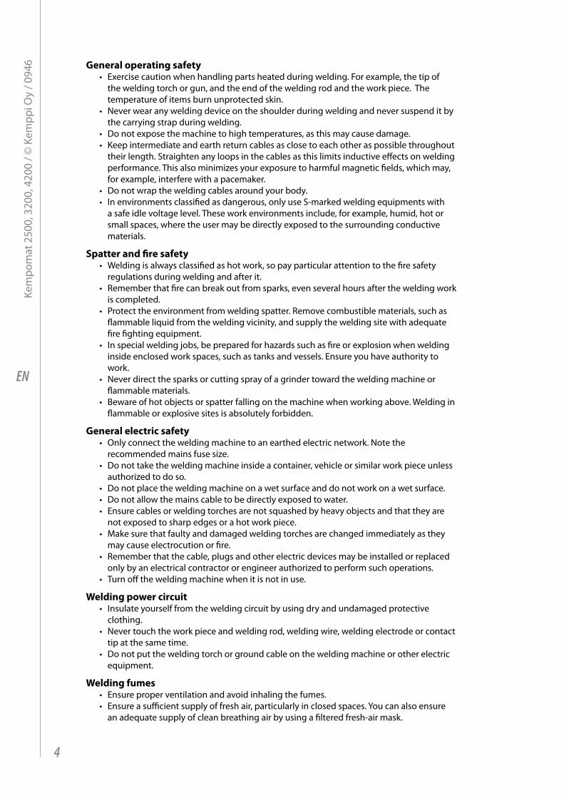
2.1 siting the maChineSite the machine on a stationary, horizontal, dry and clean base from which there doesn´t come any dust etc. into inlet air through the rear grate. Ensure the free circulation of the cooling air.
• Degree of protection IP23S of the machine allows at its maximum the water jet coming in 60° angle to hit machine´s outer covering. See to that the machine is positioned away from the line of the particle spray, created by grinding tools etc.
• There must be free space in front of the machine as well as at the rear of the machine to allow good circulation of the cooling air through the machine.
• Protect the machine against straight rain and in circumstances over 25 °C against direct sunshine.
60 °
max. 15 °
2.2 COnneCtiOn tO the mains supplYConnection and change of the mains cable and the plug must be carried out only by a competent electrician. Remove for the mounting of the mains cable the left side plate, seen from the front of the power source.
The Kempomat power source is equipped with 5 m supply cable without plug. The mains cable is according to the marking H07RN-F of the norm CENELEC HD22. The mains cable must be changed if it doesn´t meet local regulations.
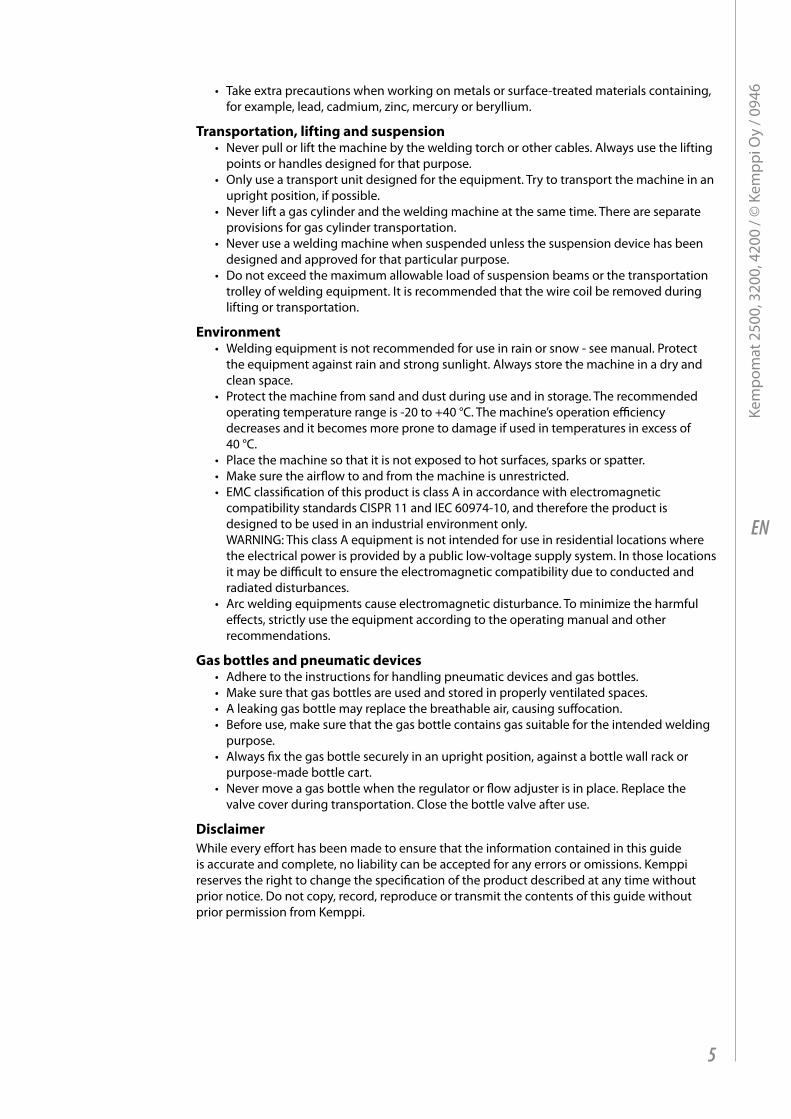
2.3 mOunting OF the mains CableThe cable is entered into the machine through the inlet ring on the rear wall of the machine and locked with a cable clamp (05).
The phase conductors of the cable are coupled to connectors L1, L2 and L3. The earth protection coloured green-yellow is coupled to connector marked with earth protection symbol . If you are using 5-conductor cable, you must cut the zero conductor to the level of the cable´s protective shield.
In cables of S type there is protective grounding conductor coloured green-yellow.
L1L2L3
Kempomat 2500 3200 4200Connection voltage 230 V 400 V 230 V 400 V 230 V 400 V
Connection cable 4G2.5 (5 m) 4G2.5 (5 m) 4G2.5 (5 m) 4G2.5 (5 m) 4G6.0 (5 m) 4G2.5 (5 m)
Fuse, delayed 16 A 10 A 20 A 16 A 25 A 16 A
6
Kem
pom
at 2
500,
320
0, 4
200
/ © K
empp
i Oy
/ 094
6
EN
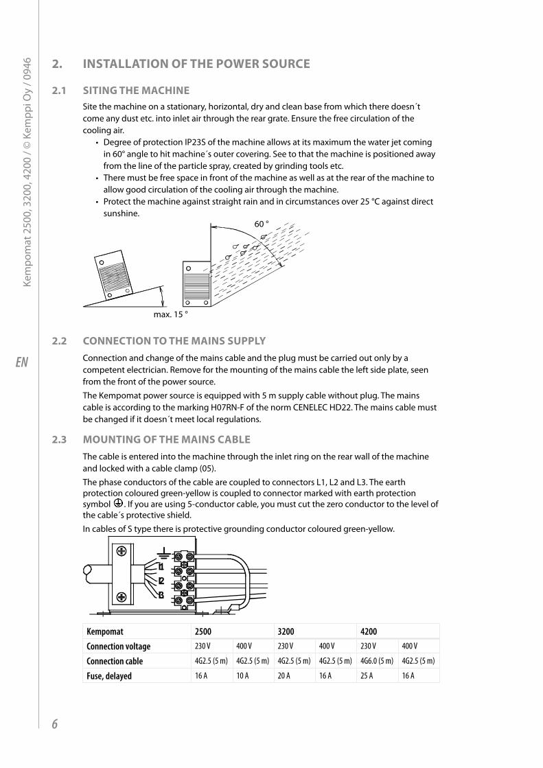
Change of mains voltage / Kempomat 2500, 3200Connection and change of the mains cable and the plug must be carried out only by a competent electrician.
230 V201204203206205202
230 V
T002
400 V
230 V
0
201204203206205202
400 V
400 V
T002
400 V
230 V
0
Connection 3~ 230 or 3~ 400 V of mains voltageBy delivery from the factory the Kempomat 3200 and 2500 machine has been connected for mains voltage 3~ 400 V. In order to change the mains voltage in the Kempomat 2500/3200 machine, remove the side plate of the machine. Change the connections according to the enclosed diagram. You find the corresponding wiring diagram on the instruction label, which is under terminal block.
NOTE! The Kempomat 4200 machine has the connection for only one mains voltage!
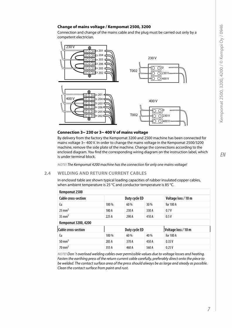
2.4 welding and return Current CablesIn enclosed table are shown typical loading capacities of rubber insulated copper cables, when ambient temperature is 25 °C and conductor temperature is 85 °C.
Kempomat 2500Cable cross-section Duty cycle ED Voltage loss / 10 mCu 100 % 60 % 30 % for 100 A
25 mm² 180 A 230 A 330 A 0.7 V
35 mm² 225 A 290 A 410 A 0.5 V
Kempomat 3200, 4200
Cable cross-section Duty cycle ED Voltage loss / 10 mCu 100 % 60 % 40 % for 100 A
50 mm² 285 A 370 A 450 A 0.35 V
70 mm² 355 A 460 A 560 A 0.25 V
NOTE! Don´t overload welding cables over permissible values due to voltage losses and heating. Fasten the earthing press of the return current cable carefully, preferably direct onto the piece to be welded. The contact surface area of the press should always be as large and steady as possible. Clean the contact surface from paint and rust.
7
Kem
pom
at 2
500,
320
0, 4
200
/ © K
empp
i Oy
/ 094
6
EN
3. use OF wireFeeder
3.1 parts OF wire Feed meChanism
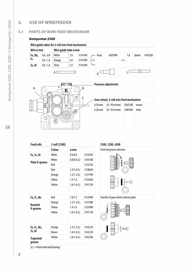
Kempomat 2500
Wire guide tubes for 2-roll wire feed mechanismWire ø mm Wire guide tube ø mmFe, Mc, Fc
0,6...0,8 White 1,0 3134140 brass 4285900 1,8 plastic 4102283
0,9...1,6 Orange 2,0 3133700
Ss, Al 0,8...1,6 Silver 2,5 3134290
A. B. C.
A. B.
C.
Pressure adjustment
Gear wheel, 2-roll wire feed mechanismø 28 mm (0–18 m/min) 4265240 muovi
ø 28 mm (0–18 m/min) 4287860 teräs
Feed rolls 2-roll (2500) 2500, 3200, 4200Colour ø mm Feed roll groove selection
Fe, Ss, Al
Plain V-groove
White 0.6/0.8 3133810
White 0.8/0.8 (L) 3143180
Red 3133210
Red 1.0/1.0 (L) 3138650
Orange 1.2/1.2 (L) 3137390
Yellow 1.4-1.6 3133820
Yellow 1.6/1.6 (L) 3141120
Fe, Fc, Mc
Knurled V-groove
Red 1.0/1.2 3133940 Transfer of gear wheel selector plate
Orange 1.2/1.2 (L) 3137380
Yellow 1.4-1.6 3133990
Yellow 1.6/1.6 (L) 3141130
Fe, Fc, Mc, Ss, Al
Trapezoid groove
Orange 1.2/1.2 (L) 3142210
Brown 1.4/1.4 (L) 3142220
Yellow 1.6/1.6 (L) 3142200
(L) = Fitted with ball bearings
8
Kem
pom
at 2
500,
320
0, 4
200
/ © K
empp
i Oy
/ 094
6
EN
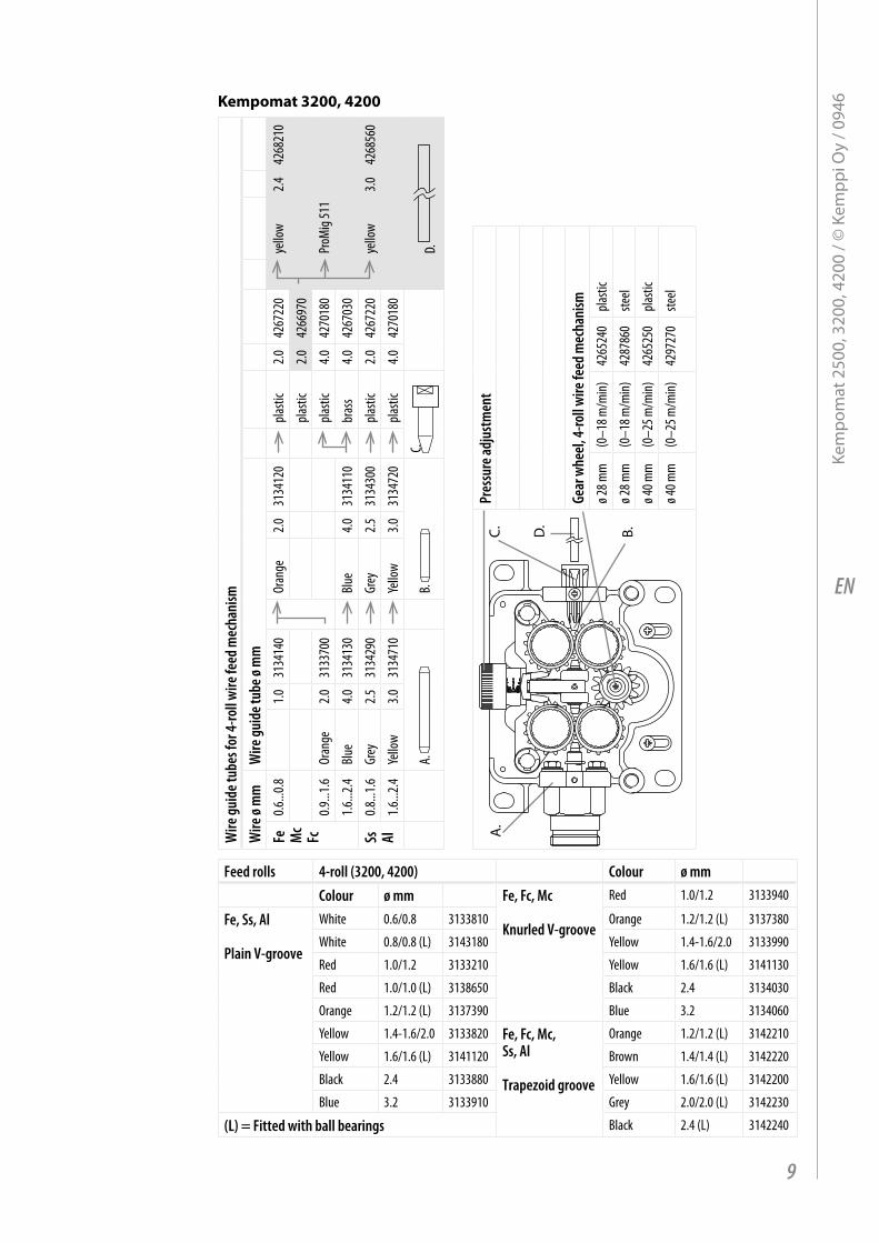
Kempomat 3200, 4200
Wire
guid
e tub
es fo
r 4-ro
ll wire
feed
mec
hani
smW
ire ø
mm
Wire
guid
e tub
e ø m
mFe M
cFc
0.6...0
.81.0
3134
140
Oran
ge2.0
3134
120
plasti
c2.0
4267
220
yello
w2.4
4268
210
plasti
c2.0
4266
970
0.9...1
.6Or
ange
2.031
3370
0pla
stic
4.042
7018
0Pr
oMig
511
1.6...2
.4Bl
ue4.0
3134
130
Blue
4.031
3411
0br
ass
4.042
6703
0
Ss Al0.8
...1.6
Grey
2.531
3429
0Gr
ey2.5
3134
300
plasti
c2.0
4267
220
yello
w3.0
4268
560
1.6...2
.4Ye
llow
3.031
3471
0Ye
llow
3.031
3472
0pla
stic
4.042
7018
0
A.
B.
C. D.
A.
C. D.
B.
Pres
sure
adju
stmen
t
Gear
whe
el, 4-
roll w
ire fe
ed m
echa
nism
ø 28 m
m(0
–18 m
/min)
4265
240
plasti
c
ø 28 m
m(0
–18 m
/min)
4287
860
steel
ø 40 m
m(0
–25 m
/min)
4265
250
plasti
c
ø 40 m
m(0
–25 m
/min)
4297
270
steel
Feed rolls 4-roll (3200, 4200) Colour ø mmColour ø mm Fe, Fc, Mc
Knurled V-groove
Red 1.0/1.2 3133940
Fe, Ss, Al
Plain V-groove
White 0.6/0.8 3133810 Orange 1.2/1.2 (L) 3137380
White 0.8/0.8 (L) 3143180 Yellow 1.4-1.6/2.0 3133990
Red 1.0/1.2 3133210 Yellow 1.6/1.6 (L) 3141130
Red 1.0/1.0 (L) 3138650 Black 2.4 3134030
Orange 1.2/1.2 (L) 3137390 Blue 3.2 3134060
Yellow 1.4-1.6/2.0 3133820 Fe, Fc, Mc, Ss, Al
Trapezoid groove
Orange 1.2/1.2 (L) 3142210
Yellow 1.6/1.6 (L) 3141120 Brown 1.4/1.4 (L) 3142220
Black 2.4 3133880 Yellow 1.6/1.6 (L) 3142200
Blue 3.2 3133910 Grey 2.0/2.0 (L) 3142230
(L) = Fitted with ball bearings Black 2.4 (L) 3142240
9
Kem
pom
at 2
500,
320
0, 4
200
/ © K
empp
i Oy
/ 094
6
EN
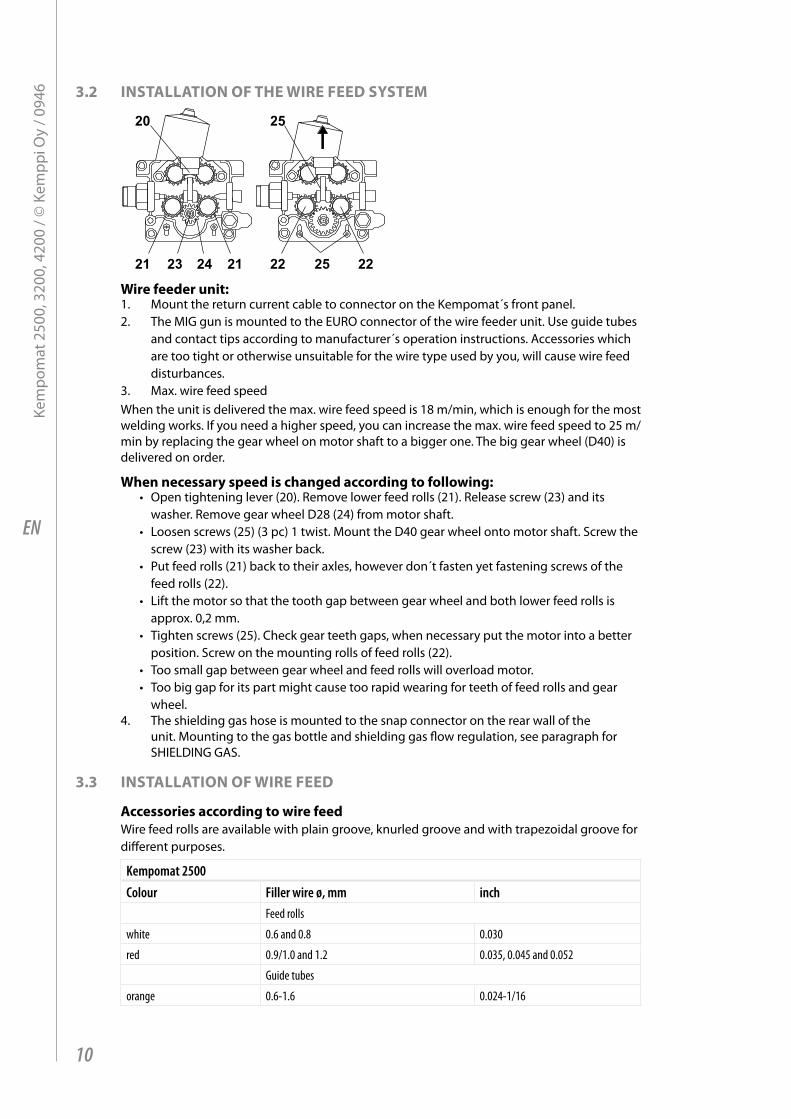
3.2 installatiOn OF the wire Feed sYstem
wire feeder unit:1. Mount the return current cable to connector on the Kempomat´s front panel.2. The MIG gun is mounted to the EURO connector of the wire feeder unit. Use guide tubes
and contact tips according to manufacturer´s operation instructions. Accessories which are too tight or otherwise unsuitable for the wire type used by you, will cause wire feed disturbances.
3. Max. wire feed speedWhen the unit is delivered the max. wire feed speed is 18 m/min, which is enough for the most welding works. If you need a higher speed, you can increase the max. wire feed speed to 25 m/min by replacing the gear wheel on motor shaft to a bigger one. The big gear wheel (D40) is delivered on order.
when necessary speed is changed according to following:• Open tightening lever (20). Remove lower feed rolls (21). Release screw (23) and its
washer. Remove gear wheel D28 (24) from motor shaft.• Loosen screws (25) (3 pc) 1 twist. Mount the D40 gear wheel onto motor shaft. Screw the
screw (23) with its washer back.• Put feed rolls (21) back to their axles, however don´t fasten yet fastening screws of the
feed rolls (22).• Lift the motor so that the tooth gap between gear wheel and both lower feed rolls is
approx. 0,2 mm.• Tighten screws (25). Check gear teeth gaps, when necessary put the motor into a better
position. Screw on the mounting rolls of feed rolls (22).• Too small gap between gear wheel and feed rolls will overload motor.• Too big gap for its part might cause too rapid wearing for teeth of feed rolls and gear
wheel.4. The shielding gas hose is mounted to the snap connector on the rear wall of the
unit. Mounting to the gas bottle and shielding gas flow regulation, see paragraph for SHIELDING GAS.
3.3 installatiOn OF wire Feed
accessories according to wire feedWire feed rolls are available with plain groove, knurled groove and with trapezoidal groove for different purposes.
Kempomat 2500Colour Filler wire ø, mm inch
Feed rolls
white 0.6 and 0.8 0.030
red 0.9/1.0 and 1.2 0.035, 0.045 and 0.052
Guide tubes
orange 0.6-1.6 0.024-1/16
10
Kem
pom
at 2
500,
320
0, 4
200
/ © K
empp
i Oy
/ 094
6
EN
Kempomat 3200, 4200Colour Filler wire ø, mm inch
Feed rolls
white 0.6 and 0.8 0.030
red 0.9/1.0 and 1.2 0.035, 0.045 and 0.052
yellow 1.4, 1.6 and 2.0 1/16 and 5/64
Guide tubes
orange 0.6-1.6 0.024-1/16
Feed roll with plain groove:Universal feed roll for welding of all kinds of wires
Feed rolls with knurled groove:Special feed roll for cored wires and steel wires
Feed rolls with trapezoidal groove:Special feed roll for aluminium wiresWire feed rolls have two grooves for different filler wire diameters. Correct wire groove is selected by moving selecting washer from one side to another in feed roll.Feed rolls and wire guide tubes have colour codes in order to make identification easier.By delivery Kempomat is equipped with red feed rolls with plain groove and with orange wire guide tubes for welding filler wires 0.9 - 1.2 mm (0.035”, 0.045” and 0.052”).
3.4 mOunting OF mig welding gunIn order to ensure trouble-free welding check in operation instructions of gun used by you that wire guide tube and contact tip of gun are according to manufacturer´s recommendation suitable to be used for wire feed diameter and type in question. Too tight a wire guide tube might cause for wire feeder unit a bigger stress than normally as well as disturbances in wire feed.Screw snap connector of gun tight that there won´t come any voltage losses on connecting surface.A loose connection will heat gun and wire feeder unit.
NOTE! Make sure that the welding gun in your use is designed for max. welding current needed by you! Never use a damaged welding gun!
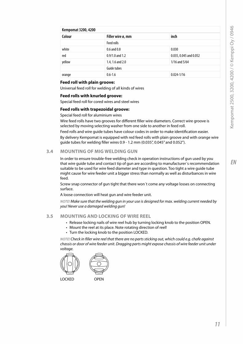
3.5 mOunting and lOCKing OF wire reel• Release locking nails of wire reel hub by turning locking knob to the position OPEN.• Mount the reel at its place. Note rotating direction of reel!• Turn the locking knob to the position LOCKED.
NOTE! Check in filler wire reel that there are no parts sticking out, which could e.g. chafe against chassis or door of wire feeder unit. Dragging parts might expose chassis of wire feeder unit under voltage.
LOCKED OPEN
11
Kem
pom
at 2
500,
320
0, 4
200
/ © K
empp
i Oy
/ 094
6
EN
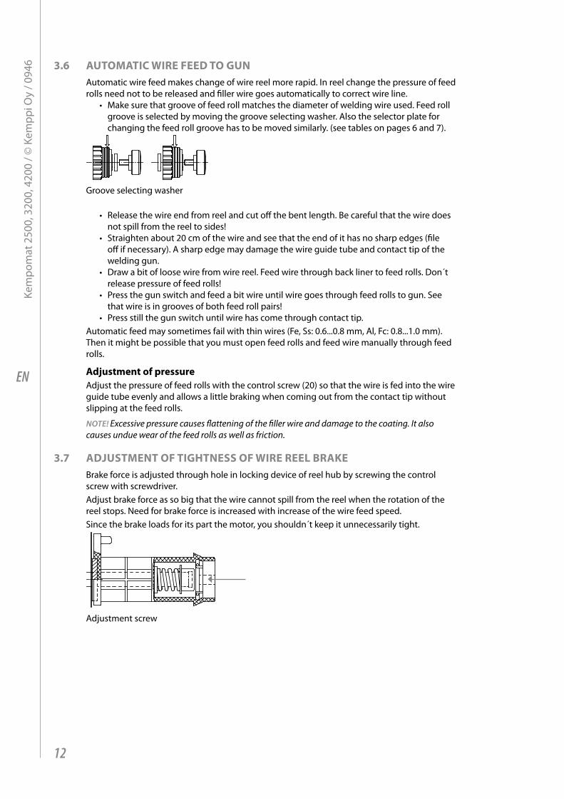
3.6 autOmatiC wire Feed tO gunAutomatic wire feed makes change of wire reel more rapid. In reel change the pressure of feed rolls need not to be released and filler wire goes automatically to correct wire line.
• Make sure that groove of feed roll matches the diameter of welding wire used. Feed roll groove is selected by moving the groove selecting washer. Also the selector plate for changing the feed roll groove has to be moved similarly. (see tables on pages 6 and 7).
Groove selecting washer
• Release the wire end from reel and cut off the bent length. Be careful that the wire does not spill from the reel to sides!
• Straighten about 20 cm of the wire and see that the end of it has no sharp edges (file off if necessary). A sharp edge may damage the wire guide tube and contact tip of the welding gun.
• Draw a bit of loose wire from wire reel. Feed wire through back liner to feed rolls. Don´t release pressure of feed rolls!
• Press the gun switch and feed a bit wire until wire goes through feed rolls to gun. See that wire is in grooves of both feed roll pairs!
• Press still the gun switch until wire has come through contact tip.Automatic feed may sometimes fail with thin wires (Fe, Ss: 0.6...0.8 mm, Al, Fc: 0.8...1.0 mm). Then it might be possible that you must open feed rolls and feed wire manually through feed rolls.
adjustment of pressureAdjust the pressure of feed rolls with the control screw (20) so that the wire is fed into the wire guide tube evenly and allows a little braking when coming out from the contact tip without slipping at the feed rolls.
NOTE! Excessive pressure causes flattening of the filler wire and damage to the coating. It also causes undue wear of the feed rolls as well as friction.
3.7 adjustment OF tightness OF wire reel braKeBrake force is adjusted through hole in locking device of reel hub by screwing the control screw with screwdriver.Adjust brake force as so big that the wire cannot spill from the reel when the rotation of the reel stops. Need for brake force is increased with increase of the wire feed speed.Since the brake loads for its part the motor, you shouldn´t keep it unnecessarily tight.
Adjustment screw
12
Kem
pom
at 2
500,
320
0, 4
200
/ © K
empp
i Oy
/ 094
6
EN
3.8 shielding gasAs MIG shielding gas is used carbon dioxide, mixed gases and argon. Shielding gas flow rate is defined by welding current size. Typical rate of gas in welding of steel is 8-15 l / min.
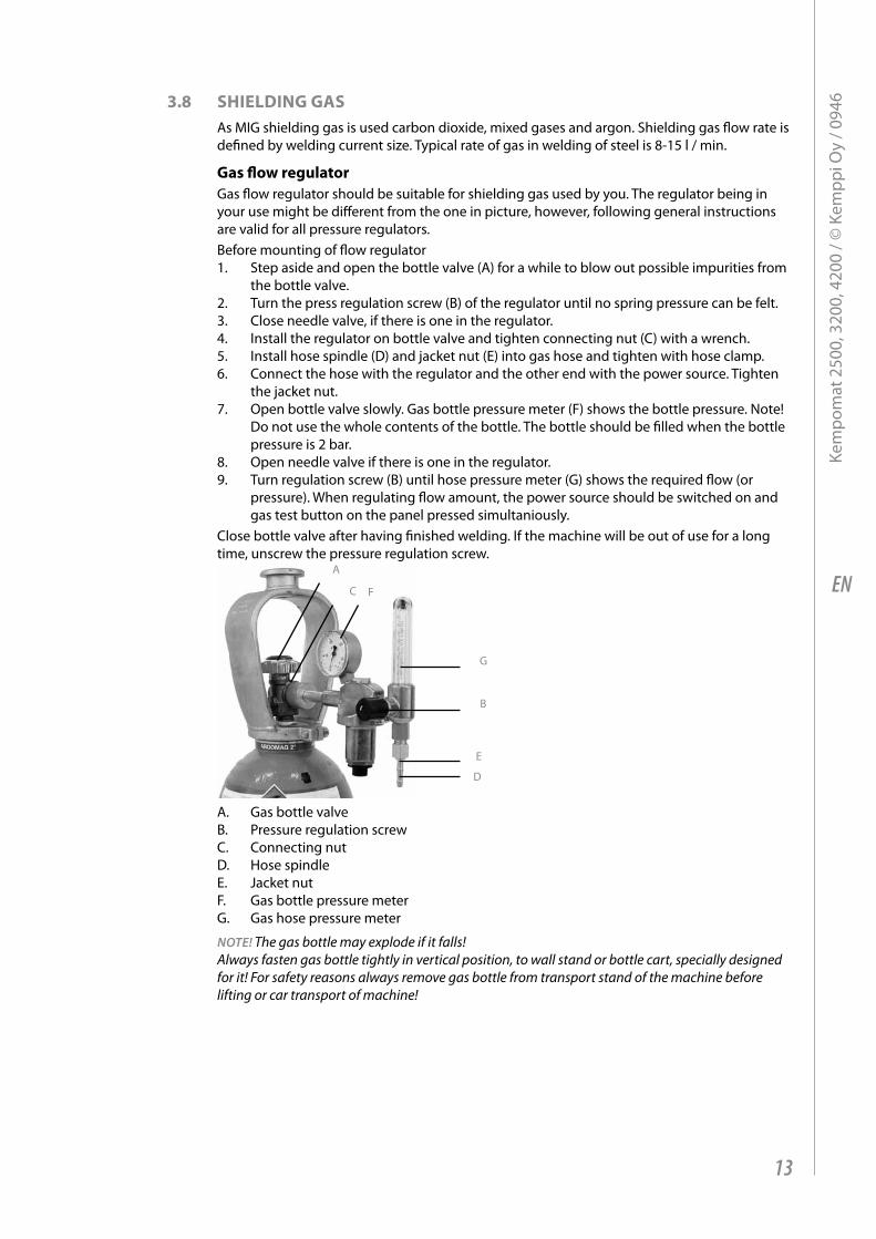
gas flow regulatorGas flow regulator should be suitable for shielding gas used by you. The regulator being in your use might be different from the one in picture, however, following general instructions are valid for all pressure regulators.Before mounting of flow regulator1. Step aside and open the bottle valve (A) for a while to blow out possible impurities from
the bottle valve.2. Turn the press regulation screw (B) of the regulator until no spring pressure can be felt. 3. Close needle valve, if there is one in the regulator.4. Install the regulator on bottle valve and tighten connecting nut (C) with a wrench.5. Install hose spindle (D) and jacket nut (E) into gas hose and tighten with hose clamp.6. Connect the hose with the regulator and the other end with the power source. Tighten
the jacket nut.7. Open bottle valve slowly. Gas bottle pressure meter (F) shows the bottle pressure. Note!
Do not use the whole contents of the bottle. The bottle should be filled when the bottle pressure is 2 bar.
8. Open needle valve if there is one in the regulator.9. Turn regulation screw (B) until hose pressure meter (G) shows the required flow (or
pressure). When regulating flow amount, the power source should be switched on and gas test button on the panel pressed simultaniously.
Close bottle valve after having finished welding. If the machine will be out of use for a long time, unscrew the pressure regulation screw.
E
B
D
C
A
F
G
A. Gas bottle valveB. Pressure regulation screwC. Connecting nutD. Hose spindleE. Jacket nutF. Gas bottle pressure meterG. Gas hose pressure meter
NOTE! The gas bottle may explode if it falls! Always fasten gas bottle tightly in vertical position, to wall stand or bottle cart, specially designed for it! For safety reasons always remove gas bottle from transport stand of the machine before lifting or car transport of machine!
13
Kem
pom
at 2
500,
320
0, 4
200
/ © K
empp
i Oy
/ 094
6
EN
4. OperatiOn and use OF pOwer sOurCe
4.1 KempOmat panels
1. 13.
14.
15.
16.
2.
3.
4.
5.
6.
7.8.
9.
10.
11.
12.
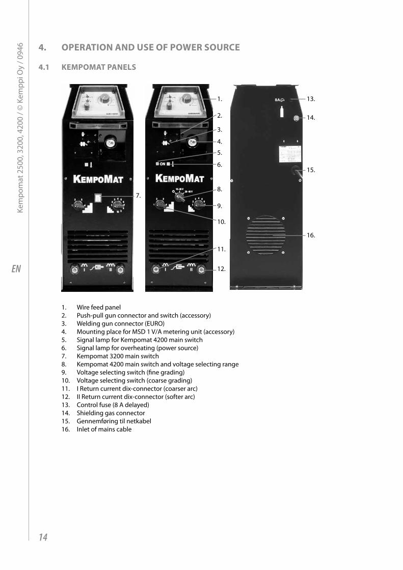
1. Wire feed panel2. Push-pull gun connector and switch (accessory)3. Welding gun connector (EURO)4. Mounting place for MSD 1 V/A metering unit (accessory)5. Signal lamp for Kempomat 4200 main switch6. Signal lamp for overheating (power source)7. Kempomat 3200 main switch8. Kempomat 4200 main switch and voltage selecting range9. Voltage selecting switch (fine grading)10. Voltage selecting switch (coarse grading)11. I Return current dix-connector (coarser arc)12. II Return current dix-connector (softer arc)13. Control fuse (8 A delayed)14. Shielding gas connector15. Gennemføring til netkabel16. Inlet of mains cable
14
Kem
pom
at 2
500,
320
0, 4
200
/ © K
empp
i Oy
/ 094
6
EN
4.2 wire Feed panel
Kempomat 2500
1.
2.
1. Adjustment potentiometer for wire feed2. KMW timer, continuous/hold, continuous/spot/cycle arc, welding spot or cycle time
Kempomat 3200, 4200
1.
2.
1. Adjustment potentiometer for wire feed2. KMW timer, continuous/hold, continuous/spot/cycle arc welding, spot or cycle time
4.3 wire Feeder unit
SS Fe
ø
Al
1 10
8
654
32
7
9
BURN-BACK
WIRE INCH
1.
2.
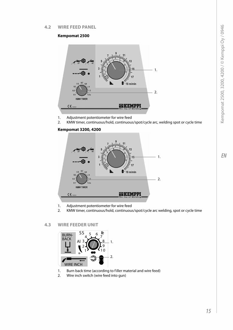
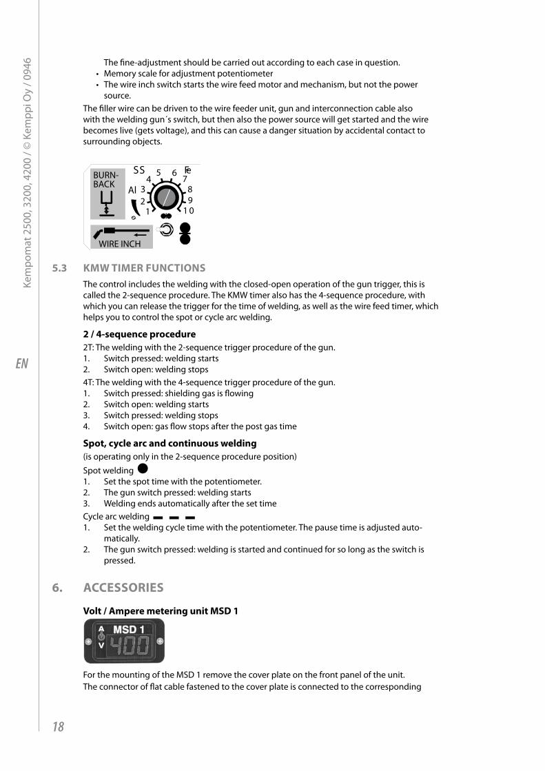
1. Burn back time (according to f iller material and wire feed)2. Wire inch switch (wire feed into gun)
15
Kem
pom
at 2
500,
320
0, 4
200
/ © K
empp
i Oy
/ 094
6
EN
4.4 main switChes and pilOt lamps
main switch (Kempomat 2500 and 3200)In zero position all control and welding current circuits of the equipment are dead (without voltage). In position I the control circuits of the machine become live (get voltage). The primary and welding circuits are dead, if the welding mode has not been started with the gun trigger.
main switch (Kempomat 4200)In zero position all control and welding current circuits of the equipment are dead (without voltage). In positions 15 - 28 V and 28 - 48 V the control circuits and cooling fan of the equipment get voltage. The primary and welding circuits are dead, if the welding mode has not been started with the gun trigger.Always switch on and switch off the machine from the main switch. Never use the mains plug for switching on or switching off the units and equipment!
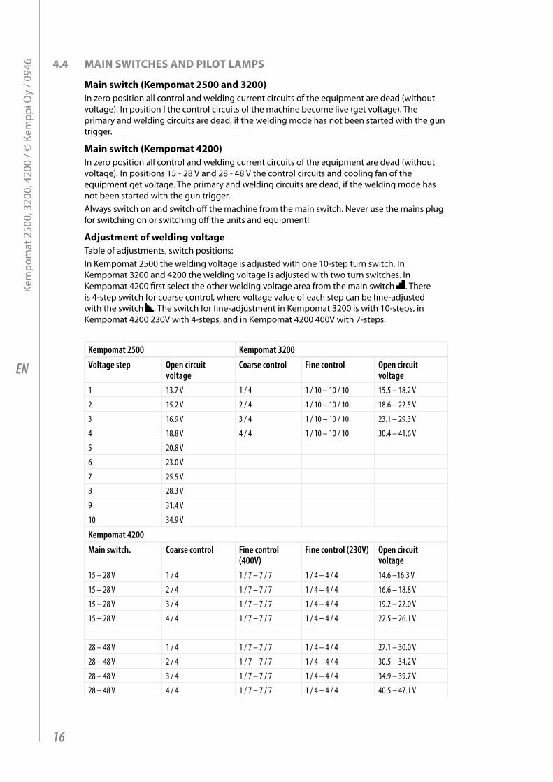
adjustment of welding voltageTable of adjustments, switch positions:In Kempomat 2500 the welding voltage is adjusted with one 10-step turn switch. In Kempomat 3200 and 4200 the welding voltage is adjusted with two turn switches. In Kempomat 4200 first select the other welding voltage area from the main switch . There is 4-step switch for coarse control, where voltage value of each step can be fine-adjusted with the switch . The switch for fine-adjustment in Kempomat 3200 is with 10-steps, in Kempomat 4200 230V with 4-steps, and in Kempomat 4200 400V with 7-steps.
Kempomat 2500 Kempomat 3200Voltage step Open circuit
voltageCoarse control Fine control Open circuit
voltage1 13.7 V 1 / 4 1 / 10 – 10 / 10 15.5 – 18.2 V
2 15.2 V 2 / 4 1 / 10 – 10 / 10 18.6 – 22.5 V
3 16.9 V 3 / 4 1 / 10 – 10 / 10 23.1 – 29.3 V
4 18.8 V 4 / 4 1 / 10 – 10 / 10 30.4 – 41.6 V
5 20.8 V
6 23.0 V
7 25.5 V
8 28.3 V
9 31.4 V
10 34.9 V
Kempomat 4200Main switch. Coarse control Fine control
(400V)Fine control (230V) Open circuit
voltage15 – 28 V 1 / 4 1 / 7 – 7 / 7 1 / 4 – 4 / 4 14.6 –16.3 V
15 – 28 V 2 / 4 1 / 7 – 7 / 7 1 / 4 – 4 / 4 16.6 – 18.8 V
15 – 28 V 3 / 4 1 / 7 – 7 / 7 1 / 4 – 4 / 4 19.2 – 22.0 V
15 – 28 V 4 / 4 1 / 7 – 7 / 7 1 / 4 – 4 / 4 22.5 – 26.1 V
28 – 48 V 1 / 4 1 / 7 – 7 / 7 1 / 4 – 4 / 4 27.1 – 30.0 V
28 – 48 V 2 / 4 1 / 7 – 7 / 7 1 / 4 – 4 / 4 30.5 – 34.2 V
28 – 48 V 3 / 4 1 / 7 – 7 / 7 1 / 4 – 4 / 4 34.9 – 39.7 V
28 – 48 V 4 / 4 1 / 7 – 7 / 7 1 / 4 – 4 / 4 40.5 – 47.1 V
16
Kem
pom
at 2
500,
320
0, 4
200
/ © K
empp
i Oy
/ 094
6
EN
pilot lamps of the machine report about electric function:The green pilot lamp indicating that the machine is ready for operation is always illuminated, when the machine is connected to mains voltage and you have selected welding voltage range from the main switch.The yellow pilot lamp for thermal protection is illuminated, when thermal protection of the welding circuit has released due to overheating. The protection releases if the power source is continuously loaded over rated values or the cooling air circulation has been obstructed.The cooling fan is cooling down the machine and after the pilot lamp has switched off, the machine is again ready for welding from the gun trigger.
Control fuseOn the rear plate of the power source the fuse 8 A delayed is the short-circuit protection. Use the fuse size and type according to markings. Damage caused by a wrong type fuse is not covered by the guarantee. If the fuse is blowing again, send the unit to service.
4.5 adjustment FOr arC rOughness Arc roughness is adjusted by connecting the return current cable to the applicable one of the two dix-connectors on the front plate.The connector marked with symbol I gives a rougher arc, which is used for welding of thin sheets and ferrous metals by 0.6 - 1.0 mm wires and especially with CO² shielding gas. The connector marked with symbol II is suitable for thicker wires and especially for aluminium and stainless materials. The most suitable roughness is, however, most dependent on the welding case. You will find the best position by testing the different positions.
4.6 OperatiOn OF COOling FanThe cooling fan on the rear plate of the Kempomat machine is started and stopped according to use. The cooling fan is started after ca. 15 s after weld start and stopped after ca. 10 min after weld end or release of the overheat protection.
NOTE! The fan is intaking air from rear plate side! Don´t switch off the unit with the main switch before the cooling fan has automatically stopped. By open circuit the cooling fan does not get started.
5. COntrOl panels and adjustments
5.1 wire Feed speed pOtentiOmeterThe wire feed speed is adjusted steplessly with the potentiometer on the front panel, see the paragraph Panels. The potentiometer has the memory scale for max. speeds of 18 m/min and 25 m/min. See the section Installation of wire feed equipment, paragraph 3. Max. wire feed speed.
5.2 burn baCK timeDifferent filler materials and shielding gases behave in different ways in the welding end, so that you should switch off the welding current with a delay, which is suitable for wire feed stopping according to the welding case.If you try to end welding with an unsuitable burn back time, the wire will burn in the contact tip, there will be too big “balloon” at the wire end, or the wire will stick at the ending point.
Factors influencing on the delay:The wire feed speed has a significant influence on required burn back time. By low wire feed speeds always select the short burn back time.
• Melting of aluminium is much quicker than by steel-base materials, so that the burn back time is clearly shorter.
• Steel and especially filler wires require longer time than the stainless materials.• Thicker filler wires require longer time. Also by increase of wire feed speed the required
time should be longer. In the instruction label are given starting points for adjustment.
17
Kem
pom
at 2
500,
320
0, 4
200
/ © K
empp
i Oy
/ 094
6
EN
The fine-adjustment should be carried out according to each case in question.• Memory scale for adjustment potentiometer• The wire inch switch starts the wire feed motor and mechanism, but not the power
source.The filler wire can be driven to the wire feeder unit, gun and interconnection cable also with the welding gun´s switch, but then also the power source will get started and the wire becomes live (gets voltage), and this can cause a danger situation by accidental contact to surrounding objects.
SS Fe
ø
Al
1 10
8
654
32
7
9
BURN-BACK
WIRE INCH
5.3 Kmw timer FunCtiOnsThe control includes the welding with the closed-open operation of the gun trigger, this is called the 2-sequence procedure. The KMW timer also has the 4-sequence procedure, with which you can release the trigger for the time of welding, as well as the wire feed timer, which helps you to control the spot or cycle arc welding.
2 / 4-sequence procedure2T: The welding with the 2-sequence trigger procedure of the gun.1. Switch pressed: welding starts2. Switch open: welding stops4T: The welding with the 4-sequence trigger procedure of the gun.1. Switch pressed: shielding gas is flowing2. Switch open: welding starts3. Switch pressed: welding stops4. Switch open: gas flow stops after the post gas time
spot, cycle arc and continuous welding (is operating only in the 2-sequence procedure position)
Spot welding 1. Set the spot time with the potentiometer.2. The gun switch pressed: welding starts3. Welding ends automatically after the set timeCycle arc welding 1. Set the welding cycle time with the potentiometer. The pause time is adjusted auto-
matically.2. The gun switch pressed: welding is started and continued for so long as the switch is
pressed.
6. aCCessOries
Volt / ampere metering unit msd 1
For the mounting of the MSD 1 remove the cover plate on the front panel of the unit. The connector of flat cable fastened to the cover plate is connected to the corresponding
18
Kem
pom
at 2
500,
320
0, 4
200
/ © K
empp
i Oy
/ 094
6
EN
connector of the MSD 1. From the metering unit you can with lever switch select momentary display for either voltage or current. By open circuit only voltage value is displayed, because there is no welding current present.
The voltage value is the voltage between the unit´s welding connectors or terminal voltage. The value of the open circuit voltage has not very much importance for the welding, so that the display of the metering unit is adjusted according to the welding situation. The display of the open circuit voltage differs 1 - 2 V from the true voltage. During welding the terminal voltage is varying and the arc voltage differs from the terminal voltage due to cable etc. losses. Accuracy of voltage true value in respect to real value is ±4.0 % ±0.2 V by welding values according to the norm. Accuracy of current true value in respect to real value is ±2.5 % ±2 A.
The metering unit doesn´t show wire feed values. The MSD 1 doesn´t need any calibration in the Kempomat units. The switch positions: V = voltage display, A = current display.
6.1 Kmw sYnCThe push-pull gun is most often used for feed of thin aluminium wires, when over 5 m reach is required. You can connect the gun equipped with the EURO adaptor to the KMW sync unit. The push-pull gun´s potentiometer is connected to amphenol connector, mounted onto front wall of the Kempomat. You can connect to this connector also some other potentiometer, which has suitable values for it. With the unit´s switch you can select the Kempomat operation or the push-pull gun operation. Concerning the right connections in the gun, contact your KEMPPI dealer.
6.2 installatiOn and mOunting OF Kmw sYnCIn the accessories of the KMW timer are included electronics card, potentiometer knob, switch protections, flat cable and fastening screws.1. Remove the side plate as well as frame and panel cover plate of the wire feed panel.2. Remove protective knobs of the holes on the panel plate.3. Mount the KMW timer electronics card in such a way that the switch levers and
potentiometer axle penetrate through the holes.4. Mount the protective caps of the switches above the levers.5. Fasten the card to back edge of the base with two screws. Don´t tighten unnecessarily
much. Mount the panel cover plate with its frame back at its place.6. Turn the potentiometer axle into clockwise direction to extreme position. Mount the
potentiometer knob onto axle in such a way that the dial line shows the reading more than 1.5 s. Check that the knob can be turned freely and that in the other extreme position the dial line shows the value less than 0.1 s. Correct if necessary. Mount the knob cap.
7. Connect one connector of the flat cable to the KMW timer card connector.8. Connect the other connector of the flat cable to connector for KMW timer on the control
card A001. 9. Fasten the side plate back at its place.
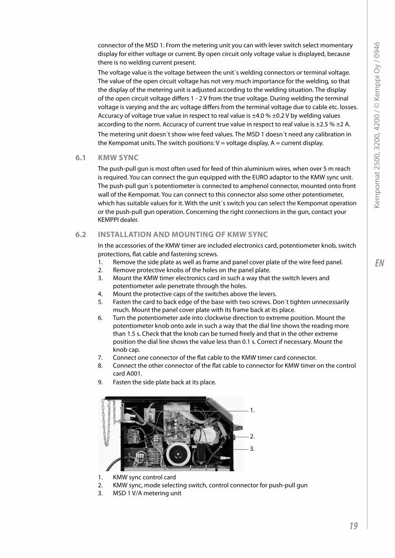
1.
2.
3.
1. KMW sync control card2. KMW sync, mode selecting switch, control connector for push-pull gun3. MSD 1 V/A metering unit
19
Kem
pom
at 2
500,
320
0, 4
200
/ © K
empp
i Oy
/ 094
6
EN
7. OperatiOn disturbanCesThe amount of use and the working environment should be taken into consideration when planning the frequency of maintenance of the Kempomat. Careful use and preventive maintenance will help to ensure trouble-free operation. The following maintenance operations should be carried out at least every six months.
wire feed:• The wear of the grooves of the feed rolls. Excessive wear of grooves causes problems in
wire feed.• The wear of the wire guide tubes of the wire feeder unit. Badly worn feed rolls and wire
guide tubes should be dis carded.• The wire guide tube should be set as near the feed rolls as possible, but not touching
them and the wire must follow a straight line from the end of the tube to the groove of the feed roll.
• Reel brake adjustment.• Electric connections *Oxidized couplings must be cleaned. *Loose couplings must be tightened.
Clean dust and dirt from the equipment.When using compressed air, always protect your eyes with proper eye protection.
8. regular maintenanCe OF the equipmentKemppi service repair shops make regular maintenance according to the agreement.The major points in the maintenance procedure are listed as follows:
• Cleaning of the machine• Checking and maintenance of the welding tools• Checking of connectors, switches and potentiometers• Checking of electric connections• Metering units checking• Checking of mains cable and plug• Damaged parts or parts in bad connection are replaced by new ones• Maintenance testing. Operation and performance values of the equipment are checked,
and adjusted when necessary by means of test equipment.The amount of use and the working environment should be taken into consideration when planning the frequency of maintenance of the machine. Careful use and preventive maintenance will help to ensure trouble-free operation.
8.1 CablesCheck the condition of welding and connection cables daily. Do not use faulty cables!Make sure that the mains connection cables in use are safe and according to regulations!The repair and mounting of mains connection cables should be carried out only by an authorized electrician.
8.2 pOwer sOurCe
NOTE! Disconnect the plug of the power source from the mains socket before removing the cover plate.
Check at least every 6 months (twice a year):• Electric connections of the unit - clean the oxidized parts and tighten the loosened ones.• NOTE! You must know correct tension torques before starting the repair of the joints.• Clean the inner parts of the machine from dust and dirt e.g. with soft brush and vacuum
cleaner.• Do not use compressed air. Do not use pressure washing device!• There is a risk that dirt is packed even more tightly into gaps of components!• Only authorized electrician shall carry out repairs to the machines.
20
Kem
pom
at 2
500,
320
0, 4
200
/ © K
empp
i Oy
/ 094
6
EN
8.3 dispOsal OF the maChine
Do not dispose of electrical equipment with normal waste!In observance of European Directive 2002/96/EC on waste electrical and electronic equipment, and its implementation in accordance with national law, electrical equipment that has reached the end of its life must be collected separately and taken to an appropriate environmentally responsible recycling facility. The owner of the equipment is obliged to deliver a decommissioned unit to a regional collection centre, per the instructions of local authorities or a Kemppi representative. By applying this European Directive you will improve the environment and human health.
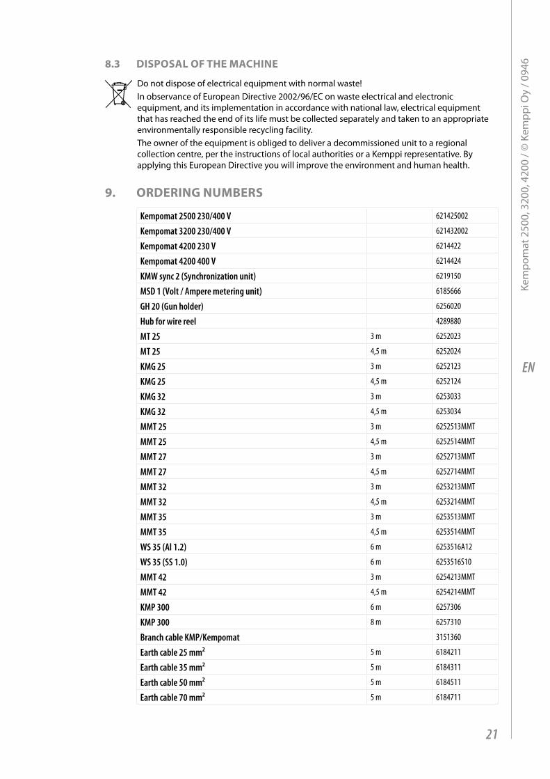
9. Ordering numbers
Kempomat 2500 230/400 V 621425002
Kempomat 3200 230/400 V 621432002
Kempomat 4200 230 V 6214422
Kempomat 4200 400 V 6214424
KMW sync 2 (Synchronization unit) 6219150
MSD 1 (Volt / Ampere metering unit) 6185666
GH 20 (Gun holder) 6256020
Hub for wire reel 4289880
MT 25 3 m 6252023
MT 25 4,5 m 6252024
KMG 25 3 m 6252123
KMG 25 4,5 m 6252124
KMG 32 3 m 6253033
KMG 32 4,5 m 6253034
MMT 25 3 m 6252513MMT
MMT 25 4,5 m 6252514MMT
MMT 27 3 m 6252713MMT
MMT 27 4,5 m 6252714MMT
MMT 32 3 m 6253213MMT
MMT 32 4,5 m 6253214MMT
MMT 35 3 m 6253513MMT
MMT 35 4,5 m 6253514MMT
WS 35 (Al 1.2) 6 m 6253516A12
WS 35 (SS 1.0) 6 m 6253516S10
MMT 42 3 m 6254213MMT
MMT 42 4,5 m 6254214MMT
KMP 300 6 m 6257306
KMP 300 8 m 6257310
Branch cable KMP/Kempomat 3151360
Earth cable 25 mm² 5 m 6184211
Earth cable 35 mm² 5 m 6184311
Earth cable 50 mm² 5 m 6184511
Earth cable 70 mm² 5 m 6184711
21
Kem
pom
at 2
500,
320
0, 4
200
/ © K
empp
i Oy
/ 094
6
EN
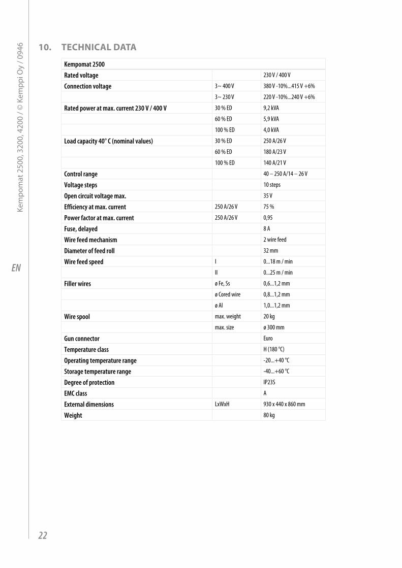
10. teChniCal data
Kempomat 2500Rated voltage 230 V / 400 V
Connection voltage 3~ 400 V 380 V -10%...415 V +6%
3~ 230 V 220 V -10%...240 V +6%
Rated power at max. current 230 V / 400 V 30 % ED 9,2 kVA
60 % ED 5,9 kVA
100 % ED 4,0 kVA
Load capacity 40° C (nominal values) 30 % ED 250 A/26 V
60 % ED 180 A/23 V
100 % ED 140 A/21 V
Control range 40 – 250 A/14 – 26 V
Voltage steps 10 steps
Open circuit voltage max. 35 V
Efficiency at max. current 250 A/26 V 75 %
Power factor at max. current 250 A/26 V 0,95
Fuse, delayed 8 A
Wire feed mechanism 2 wire feed
Diameter of feed roll 32 mm
Wire feed speed I 0...18 m / min
II 0...25 m / min
Filler wires ø Fe, Ss 0,6...1,2 mm
ø Cored wire 0,8...1,2 mm
ø Al 1,0...1,2 mm
Wire spool max. weight 20 kg
max. size ø 300 mm
Gun connector Euro
Temperature class H (180 °C)
Operating temperature range -20...+40 °C
Storage temperature range -40...+60 °C
Degree of protection IP23S
EMC class A
External dimensions LxWxH 930 x 440 x 860 mm
Weight 80 kg
22
Kem
pom
at 2
500,
320
0, 4
200
/ © K
empp
i Oy
/ 094
6
EN
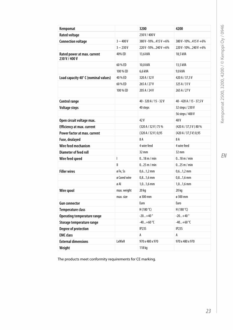
Kempomat 3200 4200Rated voltage 230 V / 400 V
Connection voltage 3 ~ 400 V 380 V -10%...415 V +6% 380 V -10%...415 V +6%
3 ~ 230 V 220 V -10%...240 V +6% 220 V -10%...240 V +6%
Rated power at max. current 230 V / 400 V
40% ED 13,6 kVA 18,5 kVA
60 % ED 10,0 kVA 13,5 kVA
100 % ED 6,6 kVA 9,0 kVA
Load capacity 40° C (nominal values) 40 % ED 320 A / 32 V 420 A / 37,5 V
60 % ED 265 A / 27 V 325 A / 31 V
100 % ED 205 A / 24 V 265 A / 27 V
Control range 40 - 320 A / 15 - 32 V 40 - 420 A / 15 - 37,5 V
Voltage steps 40 steps 32 steps / 230 V
56 steps / 400 V
Open circuit voltage max. 42 V 48 V
Efficiency at max. current (320 A / 32 V ) 75 % (420 A / 37,5 V ) 80 %
Power factor at max. current (320 A / 32 V ) 0,95 (420 A / 37,5 V) 0,95
Fuse, dealayed 8 A 8 A
Wire feed mechanism 4 wire feed 4 wire feed
Diameter of feed roll 32 mm 32 mm
Wire feed speed I 0...18 m / min 0...18 m / min
II 0...25 m / min 0...25 m / min
Filler wires ø Fe, Ss 0,6...1,2 mm 0,6...1,2 mm
ø Cored wire 0,8...1,6 mm 0,8...1,6 mm
ø Al 1,0...1,6 mm 1,0...1,6 mm
Wire spool max. weight 20 kg 20 kg
max. size ø 300 mm ø 300 mm
Gun connector Euro Euro
Temperature class H (180 °C) H (180 °C)
Operating temperature range -20...+40 ° -20...+40 °
Storage temperature range -40...+60 °C -40...+60 °C
Degree of protection IP23S IP23S
EMC class A A
External dimensions LxWxH 970 x 480 x 970 970 x 480 x 970
Weight 118 kg
The products meet conformity requirements for CE marking.
23
Kem
pom
at 2
500,
320
0, 4
200
/ © K
empp
i Oy
/ 094
6
EN
11. warrantY pOliCYKemppi Oy provides a warranty for products manufactured and sold by the company if defects in materials or workmanship occur. Warranty repairs are to be carried out only by an authorised Kemppi Service Agent. Packing, shipping, and insurance are at the orderer’s expense.The warranty starts on the date of purchase. Spoken promises not included in the terms of warranty are not binding on the warrantor.
limitations of the warrantyThe following conditions are not covered under the terms of warranty: defects arising from normal wear and tear, non-compliance with operation and maintenance instructions, overloading, negligence, connection to incorrect or faulty supply voltage (including voltage surges outside equipment specifications), incorrect gas pressure, anomalies or failures in the electric network, transport or storage damage, and fire or damage due to forces of nature. This warranty does not cover direct or indirect travel costs, daily allowances, or accommodation related to warranty service.The warranty does not cover welding torches and their consumables, feeder drive rolls,and feeder guide tubes. Direct or indirect damage caused by a defective product is not covered under the warranty. The warranty becomes void if modifications are made to the machine that are not approved by the manufacturer or if non-original spare parts are used in repairs. The warranty is also voided if repairs are carried out by a repair agent not authorised by Kemppi.
undertaking warranty repairsWarranty defects must be reported to Kemppi or an authorised Kemppi Service Agent without delay.Before a warranty repair is undertaken, the customer must present proof of warranty or otherwise prove the validity of the warranty in writing. The proof must indicate the date of purchase and the manufacturing number of the unit to be repaired. The parts replaced under the terms of this warranty remain the property of Kemppi and must be returned to Kemppi if requested.After a warranty repair, the warranty of the machine or equipment, repaired or replaced, shall be continued to the end of the original warranty period.
24
Kem
pom
at 2
500,
320
0, 4
200
/ © K
empp
i Oy
/ 094
6


www.kemppi.com 1922000 0946
KEMPPI OYHennalankatu 39PL 13FIN-15801 LAHTIFINLANDTel +358 3 899 11Telefax +358 3 899 [email protected]
Kotimaan myynti:Tel +358 3 899 11Telefax +358 3 734 [email protected]
KEMPPI SVERIGE ABBox 717S-194 27 UPPLANDS VÄSBYSVERIGETel +46 8 590 783 00Telefax +46 8 590 823 [email protected]
KEMPPI NORGE A/SPostboks 2151, PostterminalenN-3103 TØNSBERGNORGETel +47 33 346000Telefax +47 33 [email protected]
KEMPPI DANMARK A/SLiterbuen 11DK-2740 SKOVLUNDEDANMARKTel +45 4494 1677Telefax +45 4494 [email protected]
KEMPPI BENELUX B.V.Postbus 5603NL-4801 EA BREDANEDERLANDTel +31 765717750Telefax +31 [email protected]
KEMPPI (UK) LtdMartti Kemppi BuildingFraser RoadPriory Business ParkBEDFORD, MK44 3WHENGLANDTel +44 (0)845 6444201Telefax +44 (0)845 [email protected]
KEMPPI FRANCE S.A.S.65 Avenue de la Couronne des Prés78681 EPONE CEDEXFRANCETel +33 1 30 90 04 40Telefax +33 1 30 90 04 [email protected]
KEMPPI GmbHOtto-Hahn-Straße 14D-35510 BUTZBACHDEUTSCHLANDTel +49 6033 88 020Telefax +49 6033 72 [email protected]
KEMPPI SPÓŁKA Z O.O.Ul. Borzymowska 3203-565 WARSZAWAPOLANDTel +48 22 7816162Telefax +48 22 [email protected]
KEMPPI AUSTRALIA PTY LTD.13 Cullen PlaceP.O. Box 5256, Greystanes NSW 2145SMITHFIELD NSW 2164 AUSTRALIATel. +61 2 9605 9500Telefax +61 2 9605 [email protected]
OOO KEMPPIPolkovaya str. 1, Building 6127018 MOSCOWRUSSIATel +7 495 739 4304Telefax +7 495 739 [email protected]
ООО КЕМППИул. Полковая 1, строение 6127018 МоскваTel +7 495 739 4304Telefax +7 495 739 [email protected]
KEMPPI, TRADING (BEIJING) COMPANY, LIMITEDRoom 420, 3 Zone, Building B,No.12 Hongda North Street,Beijing Economic Development Zone,100176 BeijingCHINATel +86-10-6787 6064+86-10-6787 1282Telefax +86-10-6787 [email protected]
肯倍贸易(北京)有限公司中国北京经济技术开发区宏达北路12号创新大厦B座三区420室 (100176)电话: +86-10-6787 6064+86-10-6787 1282传真: +86-10-6787 [email protected]
KEMPPI INDIA PVT LTDLAKSHMI TOWERSNew No. 2/770, First Main Road, KAZURA Gardens, Neelangarai, CHENNAI - 600 041 TAMIL NADUTel +91-44-4567 1200Telefax +91-44-4567 [email protected]