Embed Size (px)
Citation preview
1
MIKE NAVARRE
BOROUGH MAYOR
ADDENDUM NO. 1 This addendum consists of 97 pages
TO: All Bid Packet Holders FROM: Kenai Peninsula Borough – Purchasing & Contracting DATE: February 22, 2013 SUBJECT: Invitation To Bid – ITB13-027 Central Peninsula Hospital Radiology Department Renovation REVISED DUE DATE: March 14, 2013, by no later than 2:00 pm
NOTICE TO BIDDERS Bidders must acknowledge receipt of this Addendum in the appropriate place on the bid form. Failure to do so may result in the disqualification or rejection of the bid. BID DUE DATE The bid due date has been rescheduled. Bids will be due March 14, 2013 no later than 2:00 PM. Note: Date for final questions will be extended to February 28, 2013. Note: Mechanical and Electrical affected by this addendum were replaced in their entirety to help for clarity. All changes should be minor in nature. Note: A minor amount of asbestos flooring and lead abatement is added by this addendum. Note: Information in his addendum takes precedence over original information. All other provisions of the document remain unchanged.
KENAI PENINSULA BOROUGH Purchasing and Contracting
144 North Binkley Street ● Soldotna, Alaska 99669-7520 Toll-free within the Borough: 1-800-478-4441, Ext. 2260
PHONE: (907) 714-2260 ● FAX: (907) 714-2373 www.borough.kenai.ak.us
2
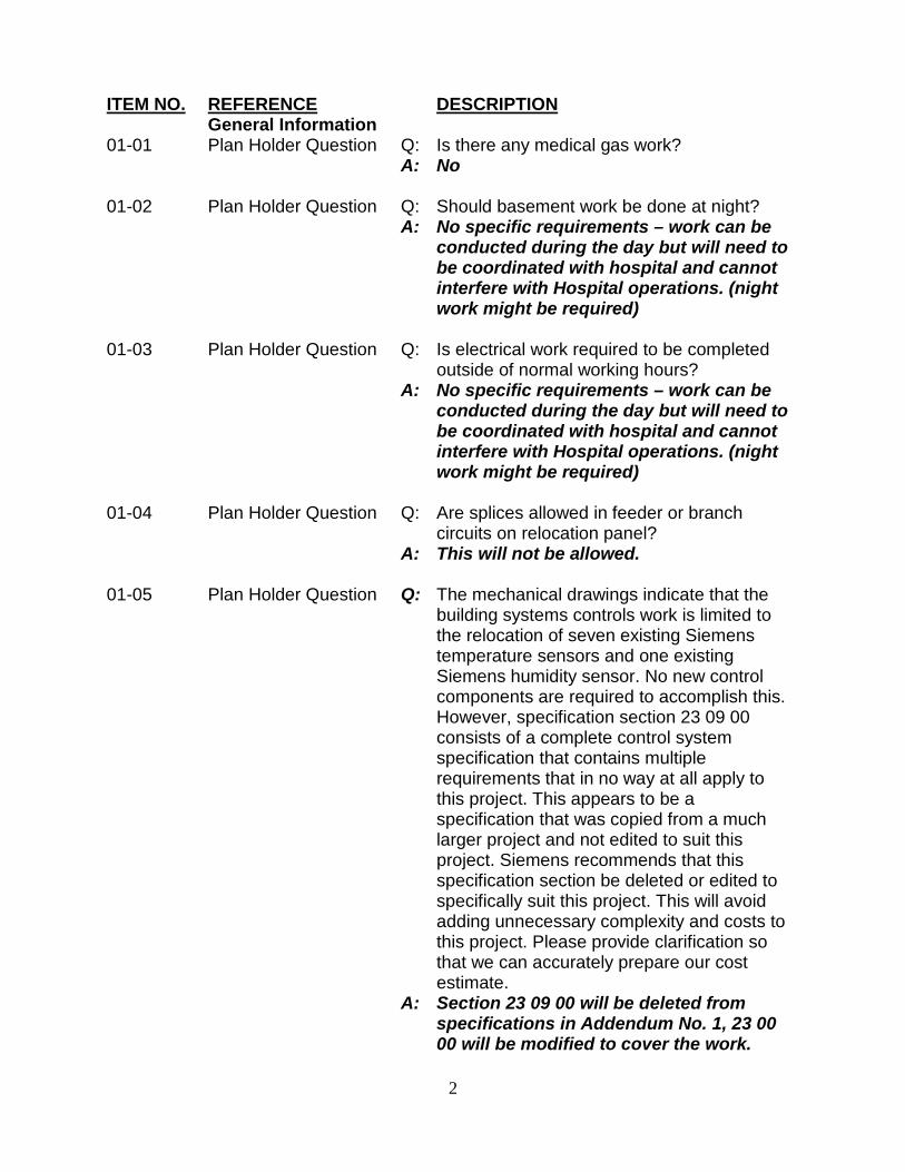
ITEM NO. REFERENCE DESCRIPTION General Information 01-01 Plan Holder Question Q: Is there any medical gas work? A: No 01-02 Plan Holder Question Q: Should basement work be done at night? A: No specific requirements – work can be
conducted during the day but will need to be coordinated with hospital and cannot interfere with Hospital operations. (night work might be required)
01-03 Plan Holder Question Q: Is electrical work required to be completed
outside of normal working hours? A: No specific requirements – work can be
conducted during the day but will need to be coordinated with hospital and cannot interfere with Hospital operations. (night work might be required)
01-04 Plan Holder Question Q: Are splices allowed in feeder or branch
circuits on relocation panel? A: This will not be allowed.
01-05 Plan Holder Question Q: The mechanical drawings indicate that the
building systems controls work is limited to the relocation of seven existing Siemens temperature sensors and one existing Siemens humidity sensor. No new control components are required to accomplish this. However, specification section 23 09 00 consists of a complete control system specification that contains multiple requirements that in no way at all apply to this project. This appears to be a specification that was copied from a much larger project and not edited to suit this project. Siemens recommends that this specification section be deleted or edited to specifically suit this project. This will avoid adding unnecessary complexity and costs to this project. Please provide clarification so that we can accurately prepare our cost estimate.
A: Section 23 09 00 will be deleted from specifications in Addendum No. 1, 23 00 00 will be modified to cover the work.
3
01-06 Plan Holder Question Q: We're missing page 1 from section 283111. The section starts on the 2nd page, and the sheet before it is blank in the pdf on your site. Please let me know if you have this sheet.
A: Section 28311 has been re-issued in its entirety in Addendum No. 1
01-07 Plan Holder Question Q: We’re missing Appendix 2 Radiation
Shielding Report from the Specifications. A: See Item 1.01.
END OF ADDENDUM NO. 1
PBS Engineering and Environmental 02 82 00 - 1 ASBESTOS ABATEMENT Central Peninsula Hospital 19 February 2013 Radiation Department Renovation Soldotna, Alaska
SECTION 02 82 00
ASBESTOS ABATEMENT PART 1 - GENERAL 1.1 SCOPE
A. This section covers the removal and disposal, or other impact, of asbestos-containing materials (ACMs) from Central Peninsula Hospital in Soldotna, Alaska as necessary to accomplish the Work as defined by these Specifications.
B. Contractor shall provide all labor, materials, equipment, services, permits and insurance required
to complete asbestos abatement procedures as indicated in this Specification.
C. Section 02 80 00 – Facilities Remediation indicates the extent of known asbestos-containing materials (ACMs) to be removed or impacted in areas of the Work. The methods acceptable are described both there and in this Specification Section.
D. The Contractor shall refer to the Hazardous Materials Inspection Report which lists suspect
materials sampled at the Central Peninsula Hospital. The Contractor shall ensure that a copy of this report is made available to and retained on the project site by all subcontractors.
1.2 RELATED WORK
A. Work performed under this specification section shall be governed by all related specification sections, including, but not limited to, the following:
1. Division 0, Contract Requirements; 2. Division 1, General Requirements; 3. Division 2, Existing Conditions: 4. Division 23, Heating, Ventilation and Air Conditioning (HVAC on drawings); 5. Division 26, Electrical (on drawings);
1.3 DEFINITIONS
A. Authorized Visitor: The Owner or designated representative, or a representative of any regulatory or other agency having jurisdiction over the project, and having required training, medical, fit test, etc.
B. Clean: Free of all visible three-dimensional dust, debris, particulate and residue, either asbestos-
containing or non-asbestos.
PBS Engineering and Environmental 02 82 00 - 2 ASBESTOS ABATEMENT Central Peninsula Hospital 19 February 2013 Radiation Department Renovation Soldotna, Alaska
C. Environmental Consultant: Environmental consultant specializing in asbestos abatement designated by the Owner.
D. Independent Testing Laboratory for Contractor Personnel Samples: A laboratory financially
independent from and hired by the Contractor which is either AIHA-accredited for asbestos with demonstrated proficiency via the AIHA PAT program, or has analysts proficient in the AIHA AAR program for air sample analysis.
E. Isolated Work Area: Regulated asbestos work area utilizing a Negative Pressure Enclosure as
defined by applicable regulations.
F. Non-isolated Work Area: Regulated asbestos work area that does not require a Negative Pressure Enclosure according to applicable regulations.
G. Owner’s Representative: Representatives designated by the Owner, or designated employees of
the Owner.
H. Work Area: A regulated area where asbestos abatement activities are performed; isolated from non-work areas by containment barriers, decontamination enclosure systems and warning signs.
1.4 DOCUMENTS INCORPORATED BY REFERENCE
A. The current issue of each document shall govern. Where conflict among requirements or with these Specifications exists, the most stringent requirements shall apply.
1. U.S. Environmental Protection Agency National Emissions Standards for Hazardous Air
Pollutants (NESHAP). (Code of Federal Regulations Title 40, Part 61, Subparts A and B.) 2. U.S. Department of Labor Occupational Safety and Health Administration (OSHA):
a. Title 29 Code of Federal Regulations Section 1910.1001--General Industry Standard
For Asbestos, and as amended by CFR (Vol. 51 #119) June 20, 1986. b. Title 29 Code of Federal Regulations Section 1910.134--General Industry Standard
For Respiratory Protection. c. Title 29 Code of Federal Regulations Section 1910 et al.--Occupational Exposure to
Asbestos; Final Rule. d. Title 29 Code of Federal Regulations 1926.1101--Construction Standard for Asbestos. e. Title 29 Code of Federal Regulations Section 1910.2--Access to Employee Exposure
and Medical. f. Title 29 Code of Federal Regulations Section 1910.1200--Hazard Communication. g. Title 29 Code of Federal Regulations Part 1926 – Construction Regulation, and as
amended by CFR (Vol. 51 #119) June 20, 1986.
3. Alaska Administrative Code (AAC), Title 8 Labor and Workforce Development, Chapter 61 Occupational Safety and Health.
PBS Engineering and Environmental 02 82 00 - 3 ASBESTOS ABATEMENT Central Peninsula Hospital 19 February 2013 Radiation Department Renovation Soldotna, Alaska
4. Environmental Protection Agency 40 CFR Part 763, AHERA, Asbestos-Containing Materials in Schools; Final Rule and Notice.
5. National Institute for Occupational Safety and Health (NIOSH), 30 CFR, Part II, Respirators.
6. American National Standards Institute (ANSI) NY; ANSI Standard Z 88.2-1980 “American National Standards Practice for Respiratory Protection”, latest edition.
7. American National Standards Institute (ANSI) NY; ANSI Publication Z9.2-79 “Fundamentals Governing the Design and Operation of Local Exhaust Systems”, latest edition.
8. CERCLA, Comprehensive Environmental Response, Compensation, and Liability Act (42 U.S.C. 9601 et.seq.).
9. RCRA, Resource Conservation and Recovery Act.
10. International Building Code (U.B.C.), latest edition, regulations as applicable.
11. Electrical work shall be performed in accordance with the National Electrical Code and as specified elsewhere.
12. All ordinances, regulations, or rules pertaining to asbestos, including its storage, transportation, and disposal.
1.5 SUBMITTALS AND NOTICES
A. Contractors shall provide one electronic copy in portable digital format (pdf) set of submittals as indicated below for review by the Owner and Environmental Consultant. Following receipt of review comments from the Owner and Environmental Consultant, submit electronic set of the revised submittals to the Owner. No asbestos-related work will be permitted prior to submittals being approved by the Environmental Consultant. Allow ten (10) days for review.
B. Additional requirements for submittals are also described in other sections of these specifications.
The requirements in this section pertain to asbestos-containing materials removal.
C. Contractors shall submit the following information prior to commencing work:
1. Statement of Qualifications: Contractor shall demonstrate the ability to perform hazardous materials abatement activities by submitting a list of references that can attest to the quality of work performed by the Contractor. Include names and locations of at least three (3) successfully completed asbestos removal projects of a similar scope and contract value, with name and phone number of project owner.
PBS Engineering and Environmental 02 82 00 - 4 ASBESTOS ABATEMENT Central Peninsula Hospital 19 February 2013 Radiation Department Renovation Soldotna, Alaska
2. Contractor must identify any citations levied against the Contractor by any federal, state or local government agencies for violations related to asbestos abatement within the last two (2) years. The General Contractor will replace any contractor disqualified under this provision at no cost to the Owner.
3. If requested by the Owner, Contractor shall submit additional evidence of successful completion of prior abatement projects, in the form of air monitoring data taken during and after completions of previous projects.
4. Contractor shall supply a copy of their state of Alaska asbestos abatement contractor’s
license.
5. Work Plan: Include a detailed plan of the procedures proposed for use in complying with the requirements, including a description of all special equipment, techniques, and methods to be used on the Project. Include in the plan a Work Area-specific schedule and identify of the Contractor's proposed independent testing laboratory to collect and analyze initial personnel exposure monitoring. Also include specific information relating to handling, transport and disposal of asbestos-containing waste. Identify any disposal site at which any waste material generated during the project will be disposed and furnish evidence of all necessary government approvals to dispose of the waste.
6. Air Monitoring: Submit information pertaining to the proposed Air Monitoring Program for this project. Air monitoring shall include employee exposure monitoring per OSHA requirements. (The Owner will facilitate pre-abatement, work area, HEPA exhaust and post-abatement monitoring.) This information shall include the name(s) of any on-site Industrial Hygiene Technician working under the foreman's supervision, types of equipment, sampling schedule, procedures, calibration record keeping, name and address of proposed Independent Testing Laboratory, and evidence of analyst's NIOSH 582 course completion and AIHA PAT program participation.
7. Worker Training: Submit evidence that all employees performing asbestos-related work have received proper training as required by 29 CFR 1910.10101 and 40 CFR Part 763, Subpart E Appendix C: EPA Model Accreditation Plan. Evidence may be in the form of a written statement attesting to the training status of employees performing asbestos-related work, with a principal of the firm as signatory. Make available immediately on request by the Owner or its agents copies of individual workers’ training certifications.
8. Written Respirator Program and Fit Testing: Submit evidence indicating that the Contractor’s written respirator program is in compliance with all parts of 29 CFR 1910.134, 29 CFR 1910.1001 and 29 CFR 1926.1101. Evidence may be in the form of a written statement attesting to the compliance status of the firm’s respiratory program, with a principal of the firm as signatory.

PBS Engineering and Environmental 02 82 00 - 5 ASBESTOS ABATEMENT Central Peninsula Hospital 19 February 2013 Radiation Department Renovation Soldotna, Alaska
9. Notifications and Policies: Submit copy of all required notifications and permits obtained by the contractor (OSHA, NESHAPS) and copies of all types of specified bonds and insurance. Amend notifications or re-notify for multi-phase activities as required by regulations.
10. Asbestos Supervisor: Submit the name, Asbestos Supervisor Certification and resume of experience of the assigned on-site foreman. At a minimum, the foreman shall have successfully completed a supervisor training course in compliance with 40 CFR Part 763 Subpart E, Appendix C: EPA Model Accreditation Plan (MAP), and shall be qualified as a competent person per 29 CFR 1926.1101. References and work on similar projects will also be reviewed. The Owner and the Environmental Consultant reserve the right to reject the foreman from the work at any time during the project. The Contractor shall then submit another on-site foreman for approval as described above.
11. Materials and Equipment: Submit Material Safety Data Sheets for all materials and equipment to be used on the project.
D. Daily Job Submittals
1. Personal Air Monitoring: Submit copies of all personal air monitoring data sheets, chain-of-
custody and analytical results to the Owner and Environmental Consultant on a daily basis prior to end of work shift following sample collection (24-hour turnaround).
2. Daily Logs: Submit daily logs to the Owner and Environmental Consultant daily, within 24 hours of completion of the work shift. Daily logs shall indicate the date, time, identity, company or agency represented, and reason for entry of all persons entering the work area. Daily logs shall also indicate the type, amount and location(s) of all ACMs removed. a. Daily logs are to include a thorough description of: all regulated work areas, types of
worker protection in use, all engineering controls utilized, removal methods, water containerization types, cleaning methods, and post-removal work area conditions.
E. Post-Job Submittals shall be delivered to the Environmental Consultant within 30-days of
completion of work and shall include the following:
1. Certification: Provide written certification from the Abatement Contractor's Project Manager or Supervisor that Contractor has fully inspected the work area and completed work in strict accordance with the Specifications.
2. Air Monitoring: Submit documentation of all employee personal air monitoring results relative to OSHA respiratory protection level compliance. Include copies of all air monitoring data sheets, chain-of-custody documentation and analysis reports for sampling conducted at the site.
PBS Engineering and Environmental 02 82 00 - 6 ASBESTOS ABATEMENT Central Peninsula Hospital 19 February 2013 Radiation Department Renovation Soldotna, Alaska
3. Project Record Documents: Provide project records including documentation of all contract changes, and copies of worksite entry log books, safety logs, sign-in sheets, and supervisor's daily field reports.
4. Disposal Manifests: Submit copies of all asbestos waste disposal transportation and disposal manifests including signed receipts from the landfill, and chain-of-custody.
1.6 PERSONNEL PROTECTION
A. Training
1. Prior to commencement of work, Contractor shall ensure all workers have been trained as specified in OSHA 29 CFR 1926.1101 and 8 AAC 61.600.
2. The Contractor shall provide and post decontamination, respirator, and work procedures for abatement crew.
B. Personnel Protective Equipment for Asbestos Removal - Provide protective clothing and
equipment per 29 CFR 1926.1101. Contractor is to provide appropriate protective coveralls and boots for all authorized visitors.
1.7 AIR MONITORING BY CONTRACTOR
A. Industrial Hygienist: An Independent Testing Laboratory shall be retained by the Contractor for personnel PCM sample analysis. All analysis shall be performed by an Industrial Hygienist. The Hygienist must be experienced and trained in asbestos sampling and analysis. At a minimum, documentation of prior asbestos sampling and analysis experience, plus satisfactory completion of the NIOSH 582 course or equivalent will be required. Air sample collection may be performed by an Industrial Hygienist or the Contractor's foreman at the Contractor's option. The Contractor shall perform sampling and analysis of air samples for asbestos in compliance with 29 CFR 1926.1101, Appendix A-OSHA reference method, or equivalent.
B. Sample Documentation: Documentation shall be kept for each filter sample procured as to worker
sampled, social security number, activity, work area location, date and time taken, volume of air drawn through filter, pump identification number and calibration. Documentation shall indicate in what areas tests were taken and shall clearly indicate the specified maximum allowable fiber levels for each area tested. Report all data on copies of Asbestos Air Sampling Data Form bound in these Specifications or similar approved form within 48 hours. Fill in all information on every form. Submit chain-of-custody records along with all samples.
C. Analysis Procedures: The samples shall be collected on 25 mm filters and analyzed within 12
hours using the membrane filter method at 400-450x magnification with phase contrast illumination--NIOSH Analytical Method No. 7400, or equivalent--for laboratory and field analysis. The analyst shall sign and submit permanent records of all samples analyzed directly to the Environmental Consultant. The Independent Testing Laboratory shall seal the unused portion

PBS Engineering and Environmental 02 82 00 - 7 ASBESTOS ABATEMENT Central Peninsula Hospital 19 February 2013 Radiation Department Renovation Soldotna, Alaska
of all filters in airtight containers so that individual samples can be re-analyzed at a later date if necessary. The containers shall be clearly labeled with Project Name and Sample Number and shall become property of the Owner at work completion at the Owner's request.
D. Controls: The Contractor's testing laboratory shall submit sample analysis results, chain-of-
custody and equipment calibration records to the Environmental Consultant within 24 hours of collection.
E. Contractor's Sampling During Abatement
1. Sample Collection: Air monitoring shall be performed to determine worker exposure during
the period of asbestos abatement in each work area. Begin sampling when asbestos removal commences. Samples are to be taken where Class I or II work is being conducted during each 8-hour work shift until abatement is complete. The Owner will facilitate pre-abatement, work area, HEPA exhaust and post-abatement air monitoring.
2. Most Contaminated Worker: The Contractor shall determine which worker(s) in each work area is probably experiencing the most severe exposure. 8-hour TWA and 30-minute excursion samples shall be collected on this worker(s). This worker shall wear a personal sampling pump and the sample shall be drawn from the breathing zone of this worker.
3. The number of air samples collected shall be in accordance with the Contractor's approved work plan, however, collect a minimum of one sample per work area daily.
1.8 AIR MONITORING BY OWNER
A. Industrial Hygienist: The Owner will retain an experienced Industrial Hygienist/ Environmental Consultant to collect and analyze pre-abatement, work area, HEPA exhaust and post-abatement asbestos air samples. Documentation of sample results will be forwarded to the Contractor as appropriate.
B. Sampling and analysis of asbestos samples shall be performed in compliance with 29 CFR Part
1926.1101, Appendix A--OSHA reference method, or equivalent.
C. The Owner reserves the right to monitor Contractor's performance via air samples on abatement workers in addition to the Contractor's air monitoring.
1.9 OWNER OCCUPANCY
A. The area of abatement shall be occupied only by properly trained and protected workers, and the Environmental Consultant, during abatement activities. Coordinate phasing of abatement areas to comply with occupancy requirements as defined elsewhere.
PBS Engineering and Environmental 02 82 00 - 8 ASBESTOS ABATEMENT Central Peninsula Hospital 19 February 2013 Radiation Department Renovation Soldotna, Alaska
1.10 WORKING HOURS
A. Submit proposed work schedule to Owner for approval in conjunction with submittals required by this Section. The Owner reserves the right to restrict and curtail any operations which are considered, at the Owner's sole determination, to generate such noise or activities as to interfere with facility operations. Any revisions to the approved work schedule shall be submitted in writing to the Owner a minimum of 48 hours prior to the desired change in schedule.
1.11 PERMITS AND NOTIFICATIONS
A. The Contractor is responsible for obtaining all permits and notifications as required for the completion of the work by OSHA, EPA and any other permitting agency having jurisdiction over the Work included herein.
1.12 PERSONNEL TRAINING
A. All personnel accomplishing removal of asbestos-containing materials shall have received the minimum training as required by the 29 CFR 1910.1011 and 29 CFR 2916.1101 for the work to be performed. At a minimum, the supervisor shall be the bearer of a current "Certified Asbestos Supervisor Certificate" issued by the Environmental Protection Agency or authorized delegate.
1.13 LIABILITY
A. The Contractor is an independent contractor and not an employee of the Owner, Architect or Environmental Consultant. The Owner, Architect and the Environmental Consultant shall have no liability to the Contractor or any third persons for Contractor's failure to faithfully perform and follow the provisions of these Specifications and the requirements of the governing agencies. Notwithstanding the failure of the Owner, Architect or the Environmental Consultant to discover a violation by the Contractor of any of the provisions of these Specifications, or to require the Contractor to fully perform and follow any of them, such failure shall not constitute a waiver of any of the requirements of these Specifications which shall remain fully binding upon the Contractor.
B. Contractor warrants that in complying with the Specifications of this contract it is not infringing on any patents, or rights of others in any process, procedure, methodology or equipment and agrees to indemnify and hold harmless the Owner, Architect and Environmental Consultant from any claims or losses arising from any challenge to the use by Contractor or of any process, procedure, methodology or equipment in fulfilling this contract.
1.14 SUBCONTRACTORS
PBS Engineering and Environmental 02 82 00 - 9 ASBESTOS ABATEMENT Central Peninsula Hospital 19 February 2013 Radiation Department Renovation Soldotna, Alaska
A. Subcontractors employed by the Contractor shall be bound to all the work and safety standards specified. Subcontractor's personnel shall meet requirements as specified, and shall be supervised by the Contractor during performance of this work.
1.15 QUALITY ASSURANCE
A. On-Site Observation
1. Pre-Removal: Prior to commencing asbestos-related activities, Contractor Supervisor shall perform observations regarding: demarcation of regulated area, installation of critical barriers, integrity of negative pressure enclosures, waste load-out facilities, and other conditions affecting abatement work. Documentation of pre-removal observations and any corrections shall be included in the Contractor’s daily log or other appropriate report.
2. Observation: At the discretion of the Owner, Environmental Consultant may perform observations regarding: integrity of isolation barriers, decontamination facilities, worker protection, Contractor's air monitoring program, performance of abatement operations, and conformance to the Specification, EPA and OSHA regulations.
3. Post Removal: Environmental Consultant shall perform visual inspections after the removal of asbestos-containing materials is complete. Criteria for cleanliness of work areas will be according to the definition of “clean” as described in this Section. Schedule post-removal visual inspections with the Owner a minimum of 48-hours prior to the desired inspection. Post-removal air monitoring will be completed within 4-hours of acceptable post-removal visual inspection.
4. Stop Work: Environmental Consultant shall notify the Contractor in writing to stop work if the Owner determines that work practices are in violation of regulations, these Specifications or work is endangering workers or occupants of the building. The Contractor shall continue work when conditions and actions are corrected and when written authorization is received from the Owner.
B. Air Monitoring
1. Notification: If, at any time during the work, analysis of an air sample taken by the
Contractor, Owner, or Environmental Consultant indicates a fiber concentration in excess of the Control Limits outlined below, the Industrial Hygienist who analyzed the air sample shall immediately notify the Contractor's Foreman, the Environmental Consultant, the Owner and other workers, employees, occupants, etc. in affected area(s).
2. Control Limits: Limit airborne fiber concentrations as determined by PCM analysis to the
following maximum allowable fiber concentrations:
a. Outside all regulated areas: 0.01 f/cc b. HEPA Exhaust: 0.01 f/cc c. Inside Non-isolated Regulated Work Area: 0.1 f/cc
PBS Engineering and Environmental 02 82 00 - 10 ASBESTOS ABATEMENT Central Peninsula Hospital 19 February 2013 Radiation Department Renovation Soldotna, Alaska
d. Inside Isolated Regulated Work Area: 0.1 f/cc
3. Procedures: Immediately upon being notified of fiber concentration in excess of the applicable Control Limit, the Contractor shall perform the following steps in the order presented, at no additional cost to the Owner:
a. Stop abatement work and identify source of high fiber counts. b. Corrective Actions: Immediately correct containment breaches, pressure differential
changes and potential cause of high fiber counts. Clean the affected area(s), finishes and items considered to be contaminated (as directed by the Environmental Consultant).
c. Clean the affected area using wet methods and HEPA vacuuming. d. Re-sample air until fiber counts are determined to be below the specified maximum
levels. e. Secure and repair containment barriers, repair or add equipment. f. Modify work procedures, and make other changes to reduce fiber counts.
4. Resume work and air monitoring.
5. Additional Costs: The Contractor shall be responsible for costs of any testing, cleanup,
repair, down time loss, etc. that is a result of the Contractor's negligence, poor maintenance of isolated areas, failed post-abatement sampling and improper procedures.
C. Performance: Work shall be performed in a skillful manner representing industry standards.
Environmental Consultant shall require Contractor to remove from the work site employees and subcontractors the Environmental Consultant deems incompetent, careless or objectionable.
PART 2 - PRODUCTS 2.1 PROTECTIVE CLOTHING AND EQUIPMENT
A. Protective Clothing: Provide approved clothing per 29 CFR 1926.1101 for all workers and all official representatives of the Owner, State or other governmental entity, and the Environmental Consultant who may require such clothing.
2.2 MATERIALS
A. Disposal containers shall be suitable to receive and retain any asbestos-containing or contaminated materials until disposal at an approved site. The containers shall be labeled with waterproof print and permanent adhesive in accordance with WAC Chapter 296-62-07721, OSHA, DOT and EPA regulations. Permanently mark the label with the date the material was collected for disposal, the name of the waste generator, the name and affiliation of the certified asbestos supervisor, and the location at which the waste was generated. Containers must be both airtight and watertight, and have hard top, bottom and sides.
PBS Engineering and Environmental 02 82 00 - 11 ASBESTOS ABATEMENT Central Peninsula Hospital 19 February 2013 Radiation Department Renovation Soldotna, Alaska
B. Encapsulants (Sealants): Encapsulants shall be rated as "Acceptable" using the test method described in the EPA document published as National Technical Information Service report PB
C. Plastic Sheeting: Plastic sheeting shall be fire retardant in compliance with applicable fire codes,
minimum 6-mil in thickness.
D. Solvents: Solvents used for removal of adhesives, sealants or caulkings from substrate(s) shall be acceptable for installation of replacement materials.
PART 3 - EXECUTION 3.1 WORK AREA PREPARATION
A. Performance: Contractor shall perform the following procedures in the order in which they are presented for work according to the approved work plan.
1. Coordinate shut down of HVAC systems with Owner. Seal HVAC openings with two
separate layers of plastic sheeting.
2. Restrict access to work area and post warning signs. Do not perform abatement work in an occupied area.
3. Completely pre-clean any visible accumulation of asbestos debris in work area using HEPA vacuum equipment or wet cleaning methods.
4. Set up a worker decontamination enclosure system satisfying requirements of OSHA 1926.1101. Once this system is installed and abatement commences, it shall be utilized in the specified manner for the ingress and egress of only personnel. All personnel shall sign the Worksite Entry Logbook each time they pass in or out of the modified decontamination enclosure system.
5. Install HEPA air-purifying equipment pressure differential fan system. Discharge from air-purifying equipment shall be ducted outside the building unless prior approval from the Owner has been obtained.
6. Remove or protect any finishes, furniture or equipment to remain in the work area. Do not remove any items attached or fixed to ACMs until all required critical barriers and engineering controls are in place.
7. Cover walls and other objects in work area with plastic sheeting as applicable. Seal openings as necessary to establish negative pressure or install required control barriers.
8. Have emergency cleanup equipment and supplies, including HEPA vacuum, amended water, disposal bags, mop, buckets, towels and sponges, on hand prior to start of abatement work.
PBS Engineering and Environmental 02 82 00 - 12 ASBESTOS ABATEMENT Central Peninsula Hospital 19 February 2013 Radiation Department Renovation Soldotna, Alaska
9. Post entry/exit sign in sheet at designated work area entry.
B. Compliance: No asbestos abatement work shall occur unless the work area has been found
acceptable by the Environmental Consultant.
C. Isolated work area enclosure system maintenance. The Contractor shall be responsible for daily documentation of the following:
1. Prior to the first use and at the beginning of each shift during abatement work, negative
pressure enclosures (NPEs/containments) shall be given a complete visual inspection by the Contractor's shift foreman. This shall include inspection of the HEPA air-purification system and associated filters. A smoke tube test by the shift foreman shall then be made of the worker decontamination enclosure system and other critical areas to verify that the isolated area is under negative air pressure. Work shall not begin until the inspection is completed and all defects have been repaired. Documentation of daily inspections is to be included in the Contractor’s daily logs or other appropriate report.
2. Periodic inspections shall be made during each shift to ensure proper functioning of the enclosure and HEPA pressure differential system to prevent visible emissions.
3.2 SELECTIVE DEMOLITION TO ACCESS MATERIALS TO BE ABATED
A. Contractor shall only perform demolition that is described in Construction Documents. Demolition required to access asbestos materials that is not indicated on demolition plans will not be performed until approval from Owner has been received. Contractor shall coordinate selective demolition with work of Section 02 41 19, Selective Structure Demolition.
3.3 REMOVAL/IMPACT OF ASBESTOS-CONTAINING MATERIALS
A. Perform all asbestos related work and comply with the general safety and health provisions in conformance with 29 CFR 1910.1001 and 29 CFR 1910.20, respectively. Remove and properly dispose of all asbestos-containing materials indicated to be removed in the Contract Documents in accordance with general work practices, and work practices for removal and encapsulation as specified in 40 CFR Part 61, 29 CFR 1926.1101, and other appropriate work procedures approved by the Environmental Protection Agency (EPA).
B. Contractor shall apply spray coat of amended water to asbestos materials to be removed. Keep
material damp during entire removal process. A fine mist of water shall be continuously applied to all materials being removed.
C. Contractor shall maintain a safe and uncluttered work site including staging area, work area,
worker decontamination system, and waste load-out area. All waste is to be properly containerized and labeled at the end of each work shift.
PBS Engineering and Environmental 02 82 00 - 13 ASBESTOS ABATEMENT Central Peninsula Hospital 19 February 2013 Radiation Department Renovation Soldotna, Alaska
D. Contractor shall make available at all times all regulated areas for inspection by the Environmental Consultant. At no time shall access to regulated areas be restricted to any authorized personnel.
E. Schedule post-removal inspection by the Environmental Consultant to occur following removal
of all asbestos-containing materials specified and all three-dimensional debris and dust.
F. Glovebag Abatement: Glovebag work shall be as follows. All removal using the glovebag method shall be performed strictly according to regulations, manufacturer's printed instructions, and as demonstrated by the manufacturer's representative or as further specified in this section. Glovebage abatement in hallways and work areas where other trades and Owner are operating shall be performed within mini-enclosures. A minimum of two workers are required during glovebag operations. Workers are not to smoke or wear hand or wrist jewelry while using glove bags.
1. Contractor shall coordinate with the Owner to ensure the shutoff of all sources of heat to ob-
jects to be worked on. Do no work on objects above 150º F.
2. Contractor shall install port for hose of HEPA vacuum to create reduced pressure inside glove bag. Installing of fresh air intake and/or bridging to prevent collapse of bag are ac-ceptable. Contractor shall use the smoke test method to check for leaks in each glovebag.
3. During the removal phase, Contractor shall utilize amended water to reduce potential for airborne fibers.
4. After completion of insulation removal and cleaning, but prior to removal of glove bag, Contractor shall apply a single "tack" coat of penetrating encapsulant to surface of pipe and any remaining non-asbestos insulation, within the glove bag.
5. After the pipe has been encapsulated, but prior to removal of glove bag, Contractor shall thoroughly wash the upper chamber of the glove bag and seal the contents of the bag in the lower chamber.
6. Contractor shall remove all contaminated air in the glovebag using a HEPA vacuum.
7. Contractor shall promptly double-bag the glove bag after removal is complete, place into a sealed container and remove to the bag holding enclosure.
8. Contractor shall not reuse glovebag, slide glovebag or join multiple glovebags to perform additional removal.
9. Asbestos-containing material remaining in wall and floor penetrations shall be wetted and placed in asbestos waste bag. Area shall be HEPA vacuum cleaned.
PBS Engineering and Environmental 02 82 00 - 14 ASBESTOS ABATEMENT Central Peninsula Hospital 19 February 2013 Radiation Department Renovation Soldotna, Alaska
G. Mastic Removal Solvents: Contractor is responsible for determining proper use of mastic removal solvents in relation to potentially varying substrate conditions. Inspection of all substrates prior to mastic removal is the responsibility of the Contractor, and any substrates that become contaminat-ed with dissolved mastic will disposal as ACM at no cost to the Owner. Contractor is to immedi-ately notify the Owner of any substrate conditions that may not be appropriate for use of mastic removal solvent.
1. Perform small test areas using solvent removal on flooring mastic as necessary to determine
compatibility with substrates. Substrates will vary and may consist of porous topping mate-rial that will absorb solvent.
2. Any topping materials or coatings contaminated with solvent/mastic are to be removed and
replaced at no cost to the Owner.
3. Ensure compatibility of replacement materials with any solvents used. 4. Use of solvent is strictly at the discretion of the Contractor. Utilize alternative methods for
mastic removal as warranted by substrate conditions or replacement flooring compatibility issues at no cost to the Owner.
3.4 DISPOSAL
A. Regulations: The Contractor shall determine current waste handling, transportation, and disposal regulations for the work site and for each waste disposal landfill. The Contractor must comply with these regulations and U.S. Department of Transportation, EPA and any other State or local codes, regulations or ordinances.
B. Material being transported to the pre-designated disposal site shall be double-bagged in sealed containers.
C. Waste Load-Out: Contractor shall coordinate activities to ensure that all asbestos-containing
waste is properly containerized and removed from all work areas prior to the end of each work shift. Contractor shall prevent the accumulation of waste containers within work areas and shall ensure that all waste containers are stored in lockable, properly sealed storage container(s) approved by the Owner at the end of each work shift.
1. Protect stored items and finishes located in areas of waste load-out and entry/egress. 2. Utilize waste load-out routes and times as defined in the pre-approved Work Plan.
D. Transport: Contractor shall remove decontaminated containers from site within ten calendar days
after collection for disposal at a waste disposal site operated in accordance with the provisions of 40 CFR 61.156. Notify disposal site in advance of delivery to ensure immediate disposal. Maintain chain-of-custody until accepted by the landfill.
PBS Engineering and Environmental 02 82 00 - 15 ASBESTOS ABATEMENT Central Peninsula Hospital 19 February 2013 Radiation Department Renovation Soldotna, Alaska
E. Submit disposal receipts and chain-of custody for waste within thirty (30) days of receipt of waste by landfill. Contractor shall make available all disposal manifests and receipts upon request from the Environmental Consultant or Owner.
END OF SECTION 02 82 00

SA 12 085 KENAI PENINSULA BOROUGH 2/20/2013
CPH – RADIOLOGY DEPARTMENT RENOVATION [ADD #1]
00 09 10 - 1 Addenda 1
SECTION 00 09 10
ADDENDA
ADDENDUM NUMBER 1
DATE: February 20, 2013
PROJECT: Kenai Peninsula Borough, CPH Radiology Department Renovation
PROJECT NUMBER: 12085
TO: Planholders
This addendum forms a part of the Contract Documents and modifies the Bid Set: Documents dated February 20th,
2013 with amendments and additions noted below. This Addendum consists of seven (7) pages:
CHANGES TO THE SPECIFICATIONS
Item
No.
Reference
Description
1.01 Section 00 01 10
Table of Contents
a. Add item 00 09 10 – Addendum 1
b. Add item 01 11 01 – Summary of Work – Regulated
Materials
c. Add item 02 80 00 – Facilities Remediation
d. Add item 02 82 00 – Asbestos Abatement
e. Add item 02 83 00 – Lead-Related Activities
f. Remove item 23 09 00 – Instrumentation and Control for
HVAC
g. Add item 26 24 16 – Panelboards
h. Add item 28 16 01 – Security Access Control System
i. Add item Appendix 2 – Radiation Shielding Report
1.02 Section 01 10 00
Summary of Work
a. Revise Paragraph 1.6 K to read as follows:
“Asbestos or asbestos-containing materials and lead or
lead-containing materials are located within area of
work. Locations of known hazardous materials are
indicated on drawings. The Contractor is responsible for
removal and disposal of all hazardous materials indicated
on drawings or encountered during construction.”
1.03 Section 01 11 01
Summary of Work –
Regulated Materials
a. Add new section, per attached.
1.04 Section 02 80 00
Facilities Remediation
a. Add new section, per attached.
1.05 Section 02 82 00
Asbestos Abatement
a. Add new section, per attached.
1.06 Section 02 83 00
Lead-Related Activities
a. Add new section, per attached.
1.07 Section 08 00 00
Door Schedule
Revise section, per attached.
a. Doors 1741A, 1743A, 1770A, 1771A, 1772A, 1773A, and
1774A are updated as “Existing”
b. New Hardware labels for new doors, per attached.
c. Note 12 added to Doors 1722B, 1736R, 1738R, & 1740R.
1.08 Section 08 70 10
Door Hardware
a. Update “Hardware Group No. 6”, per attached.
1.09 Section 08 80 00
Glazing
Section 2.3 Paragraph B:
a. Change material tag “AG-1” to read “RP-1” to match
SA 12 085 KENAI PENINSULA BOROUGH 2/20/2013
CPH – RADIOLOGY DEPARTMENT RENOVATION [ADD #1]
00 09 10 - 2 Addenda 1
section 09 00 01 – Finish Summary and interior elevations
on A5.01
Section 2.3 Paragraph C:
b. Add section 2.3 Paragraph C to read as follows:
“C. Art Glass (Type RP-2)
1. 3Form
a) Style: Hint Meadow + Aloe
b) Finish: Front: Hint Meadow Emboss
Back: Patent
c) Gauge: 1/2" ”
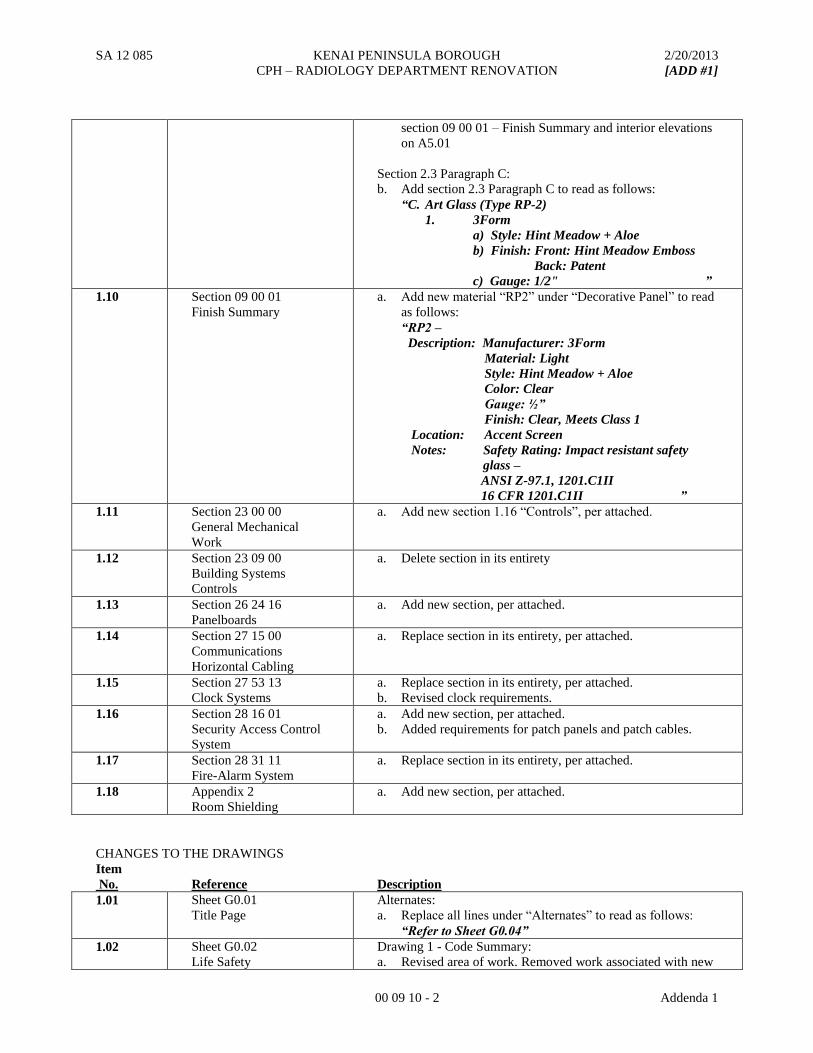
1.10 Section 09 00 01
Finish Summary
a. Add new material “RP2” under “Decorative Panel” to read
as follows:
“RP2 –
Description: Manufacturer: 3Form
Material: Light
Style: Hint Meadow + Aloe
Color: Clear
Gauge: ½”
Finish: Clear, Meets Class 1
Location: Accent Screen
Notes: Safety Rating: Impact resistant safety
glass –
ANSI Z-97.1, 1201.C1II
16 CFR 1201.C1II ”
1.11 Section 23 00 00
General Mechanical
Work
a. Add new section 1.16 “Controls”, per attached.
1.12 Section 23 09 00
Building Systems
Controls
a. Delete section in its entirety
1.13 Section 26 24 16
Panelboards
a. Add new section, per attached.
1.14 Section 27 15 00
Communications
Horizontal Cabling
a. Replace section in its entirety, per attached.
1.15 Section 27 53 13
Clock Systems
a. Replace section in its entirety, per attached.
b. Revised clock requirements.
1.16 Section 28 16 01
Security Access Control
System
a. Add new section, per attached.
b. Added requirements for patch panels and patch cables.
1.17 Section 28 31 11
Fire-Alarm System
a. Replace section in its entirety, per attached.
1.18 Appendix 2
Room Shielding
a. Add new section, per attached.
CHANGES TO THE DRAWINGS
Item
No.
Reference
Description
1.01 Sheet G0.01
Title Page
Alternates:
a. Replace all lines under “Alternates” to read as follows:
“Refer to Sheet G0.04”
1.02 Sheet G0.02
Life Safety
Drawing 1 - Code Summary:
a. Revised area of work. Removed work associated with new
SA 12 085 KENAI PENINSULA BOROUGH 2/20/2013
CPH – RADIOLOGY DEPARTMENT RENOVATION [ADD #1]
00 09 10 - 3 Addenda 1
mechanical shaft in Waiting 1024R.
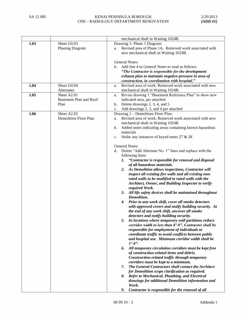
1.03 Sheet G0.03
Phasing Diagram
Drawing 1- Phase 1 Diagram:
a. Revised area of Phase 1A. Removed work associated with
new mechanical shaft in Waiting 1024R.
General Notes:
b. Add line 4 to General Notes to read as follows:
“The Contractor is responsible for the development
exhaust plan to maintain negative pressure in area of
construction, in coordination with hospital.”
1.04 Sheet G0.04
Alternates
a. Revised area of work. Removed work associated with new
mechanical shaft in Waiting 1024R.
1.05 Sheet A2.01
Basement Plan and Roof
Plan
a. Revise drawing 1 “Basement Reference Plan” to show new
indicated area, per attached.
b. Delete drawings 2, 3, 4, and 5
c. Add drawings 2, 3, and 4 per attached
1.06 Sheet A2.02
Demolition Floor Plan
Drawing 1 – Demolition Floor Plan:
a. Revised area of work. Removed work associated with new
mechanical shaft in Waiting 1024R.
b. Added notes indicating areas containing known hazardous
materials
c. Strike any instances of keyed notes 27 & 28
General Notes:
d. Delete “Add Alternate No. 1” lines and replace with the
following lines:
1. “Contractor is responsible for removal and disposal
of all hazardous materials.
2. As Demolition allows inspections, Contractor will
inspect all existing fire walls and all existing non-
rated walls to be modified to rated walls with the
Architect, Owner, and Building Inspector to verify
required Work.
3. All life safety devices shall be maintained throughout
Demolition.
4. Prior to any work shift, cover all smoke detectors
with approved covers and notify building security. At
the end of any work shift, uncover all smoke
detectors and notify building security.
5. In locations where temporary wall partitions reduce
corridor width to less than 8’-0”, Contractor shall be
responsible for employment of individuals to
coordinate traffic to avoid conflicts between public
and hospital use. Minimum corridor width shall be
5’-0”.
6. All temporary circulation corridors must be kept free
of construction-related items and debris.
Construction-related traffic through temporary
corridors must be kept to a minimum.
7. The General Contractors shall contact the Architect
for Demolition scope clarification as required.
8. Refer to Mechanical, Plumbing, and Electrical
drawings for additional Demolition information and
Work.
9. Contractor is responsible for the removal of all
SA 12 085 KENAI PENINSULA BOROUGH 2/20/2013
CPH – RADIOLOGY DEPARTMENT RENOVATION [ADD #1]
00 09 10 - 4 Addenda 1
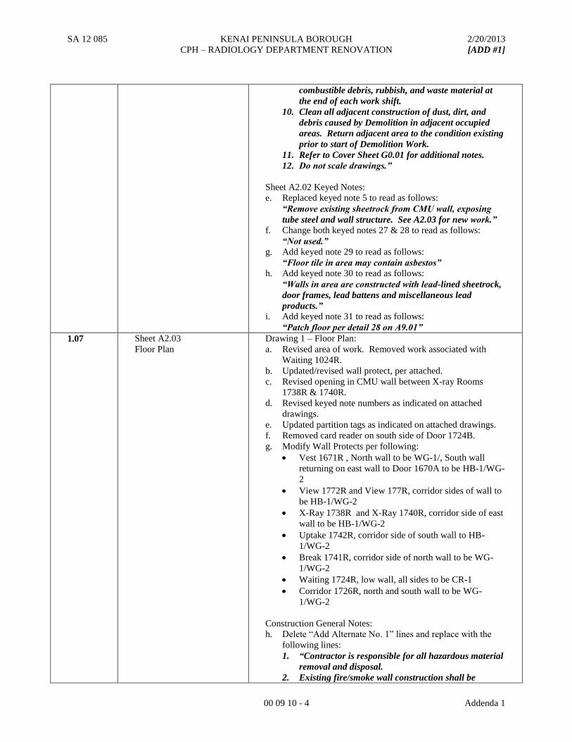
combustible debris, rubbish, and waste material at
the end of each work shift.
10. Clean all adjacent construction of dust, dirt, and
debris caused by Demolition in adjacent occupied
areas. Return adjacent area to the condition existing
prior to start of Demolition Work.
11. Refer to Cover Sheet G0.01 for additional notes.
12. Do not scale drawings.”
Sheet A2.02 Keyed Notes:
e. Replaced keyed note 5 to read as follows:
“Remove existing sheetrock from CMU wall, exposing
tube steel and wall structure. See A2.03 for new work.”
f. Change both keyed notes 27 & 28 to read as follows:
“Not used.”
g. Add keyed note 29 to read as follows:
“Floor tile in area may contain asbestos”
h. Add keyed note 30 to read as follows:
“Walls in area are constructed with lead-lined sheetrock,
door frames, lead battens and miscellaneous lead
products.”
i. Add keyed note 31 to read as follows:
“Patch floor per detail 28 on A9.01”
1.07 Sheet A2.03
Floor Plan
Drawing 1 – Floor Plan:
a. Revised area of work. Removed work associated with
Waiting 1024R.
b. Updated/revised wall protect, per attached.
c. Revised opening in CMU wall between X-ray Rooms
1738R & 1740R.
d. Revised keyed note numbers as indicated on attached
drawings.
e. Updated partition tags as indicated on attached drawings.
f. Removed card reader on south side of Door 1724B.
g. Modify Wall Protects per following:
Vest 1671R , North wall to be WG-1/, South wall
returning on east wall to Door 1670A to be HB-1/WG-
2
View 1772R and View 177R, corridor sides of wall to
be HB-1/WG-2
X-Ray 1738R and X-Ray 1740R, corridor side of east
wall to be HB-1/WG-2
Uptake 1742R, corridor side of south wall to HB-
1/WG-2
Break 1741R, corridor side of north wall to be WG-
1/WG-2
Waiting 1724R, low wall, all sides to be CR-1
Corridor 1726R, north and south wall to be WG-
1/WG-2
Construction General Notes:
h. Delete “Add Alternate No. 1” lines and replace with the
following lines:
1. “Contractor is responsible for all hazardous material
removal and disposal.
2. Existing fire/smoke wall construction shall be
SA 12 085 KENAI PENINSULA BOROUGH 2/20/2013
CPH – RADIOLOGY DEPARTMENT RENOVATION [ADD #1]
00 09 10 - 5 Addenda 1
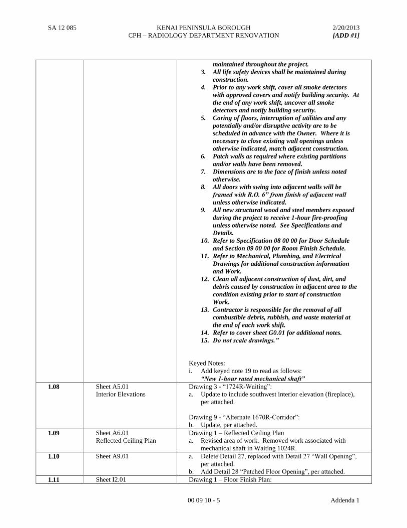
maintained throughout the project.
3. All life safety devices shall be maintained during
construction.
4. Prior to any work shift, cover all smoke detectors
with approved covers and notify building security. At
the end of any work shift, uncover all smoke
detectors and notify building security.
5. Coring of floors, interruption of utilities and any
potentially and/or disruptive activity are to be
scheduled in advance with the Owner. Where it is
necessary to close existing wall openings unless
otherwise indicated, match adjacent construction.
6. Patch walls as required where existing partitions
and/or walls have been removed.
7. Dimensions are to the face of finish unless noted
otherwise.
8. All doors with swing into adjacent walls will be
framed with R.O. 6” from finish of adjacent wall
unless otherwise indicated.
9. All new structural wood and steel members exposed
during the project to receive 1-hour fire-proofing
unless otherwise noted. See Specifications and
Details.
10. Refer to Specification 08 00 00 for Door Schedule
and Section 09 00 00 for Room Finish Schedule.
11. Refer to Mechanical, Plumbing, and Electrical
Drawings for additional construction information
and Work.
12. Clean all adjacent construction of dust, dirt, and
debris caused by construction in adjacent area to the
condition existing prior to start of construction
Work.
13. Contractor is responsible for the removal of all
combustible debris, rubbish, and waste material at
the end of each work shift.
14. Refer to cover sheet G0.01 for additional notes.
15. Do not scale drawings.”
Keyed Notes:
i. Add keyed note 19 to read as follows:
“New 1-hour rated mechanical shaft”
1.08 Sheet A5.01
Interior Elevations
Drawing 3 - “1724R-Waiting”:
a. Update to include southwest interior elevation (fireplace),
per attached.
Drawing 9 - “Alternate 1670R-Corridor”:
b. Update, per attached.
1.09 Sheet A6.01
Reflected Ceiling Plan
Drawing 1 – Reflected Ceiling Plan
a. Revised area of work. Removed work associated with
mechanical shaft in Waiting 1024R.
1.10 Sheet A9.01 a. Delete Detail 27, replaced with Detail 27 “Wall Opening”,
per attached.
b. Add Detail 28 “Patched Floor Opening”, per attached.
1.11 Sheet I2.01 Drawing 1 – Floor Finish Plan:
SA 12 085 KENAI PENINSULA BOROUGH 2/20/2013
CPH – RADIOLOGY DEPARTMENT RENOVATION [ADD #1]
00 09 10 - 6 Addenda 1
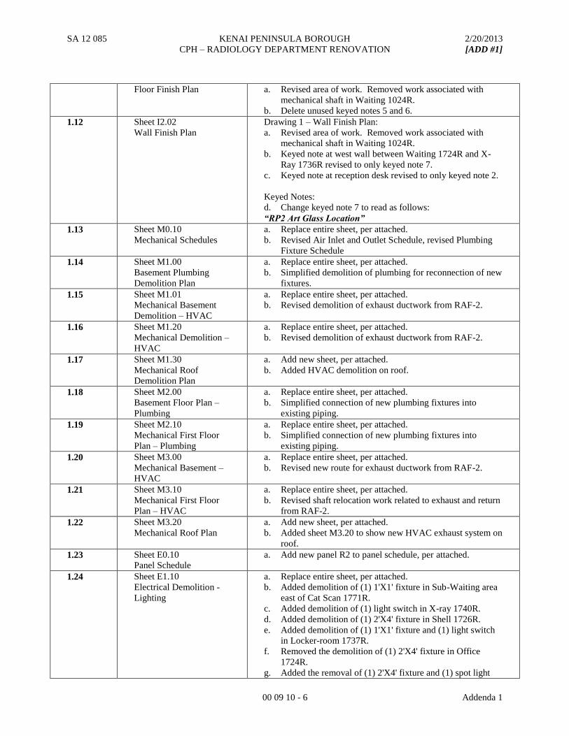
Floor Finish Plan a. Revised area of work. Removed work associated with
mechanical shaft in Waiting 1024R.
b. Delete unused keyed notes 5 and 6.
1.12 Sheet I2.02
Wall Finish Plan
Drawing 1 – Wall Finish Plan:
a. Revised area of work. Removed work associated with
mechanical shaft in Waiting 1024R.
b. Keyed note at west wall between Waiting 1724R and X-
Ray 1736R revised to only keyed note 7.
c. Keyed note at reception desk revised to only keyed note 2.
Keyed Notes:
d. Change keyed note 7 to read as follows:
“RP2 Art Glass Location”
1.13 Sheet M0.10
Mechanical Schedules
a. Replace entire sheet, per attached.
b. Revised Air Inlet and Outlet Schedule, revised Plumbing
Fixture Schedule
1.14 Sheet M1.00
Basement Plumbing
Demolition Plan
a. Replace entire sheet, per attached.
b. Simplified demolition of plumbing for reconnection of new
fixtures.
1.15 Sheet M1.01
Mechanical Basement
Demolition – HVAC
a. Replace entire sheet, per attached.
b. Revised demolition of exhaust ductwork from RAF-2.
1.16 Sheet M1.20
Mechanical Demolition –
HVAC
a. Replace entire sheet, per attached.
b. Revised demolition of exhaust ductwork from RAF-2.
1.17 Sheet M1.30
Mechanical Roof
Demolition Plan
a. Add new sheet, per attached.
b. Added HVAC demolition on roof.
1.18 Sheet M2.00
Basement Floor Plan –
Plumbing
a. Replace entire sheet, per attached.
b. Simplified connection of new plumbing fixtures into
existing piping.
1.19 Sheet M2.10
Mechanical First Floor
Plan – Plumbing
a. Replace entire sheet, per attached.
b. Simplified connection of new plumbing fixtures into
existing piping.
1.20 Sheet M3.00
Mechanical Basement –
HVAC
a. Replace entire sheet, per attached.
b. Revised new route for exhaust ductwork from RAF-2.
1.21 Sheet M3.10
Mechanical First Floor
Plan – HVAC
a. Replace entire sheet, per attached.
b. Revised shaft relocation work related to exhaust and return
from RAF-2.
1.22 Sheet M3.20
Mechanical Roof Plan
a. Add new sheet, per attached.
b. Added sheet M3.20 to show new HVAC exhaust system on
roof.
1.23 Sheet E0.10
Panel Schedule
a. Add new panel R2 to panel schedule, per attached.
1.24 Sheet E1.10
Electrical Demolition -
Lighting
a. Replace entire sheet, per attached.
b. Added demolition of (1) 1'X1' fixture in Sub-Waiting area
east of Cat Scan 1771R.
c. Added demolition of (1) light switch in X-ray 1740R.
d. Added demolition of (1) 2'X4' fixture in Shell 1726R.
e. Added demolition of (1) 1'X1' fixture and (1) light switch
in Locker-room 1737R.
f. Removed the demolition of (1) 2'X4' fixture in Office
1724R.
g. Added the removal of (1) 2'X4' fixture and (1) spot light
SA 12 085 KENAI PENINSULA BOROUGH 2/20/2013
CPH – RADIOLOGY DEPARTMENT RENOVATION [ADD #1]
00 09 10 - 7 Addenda 1
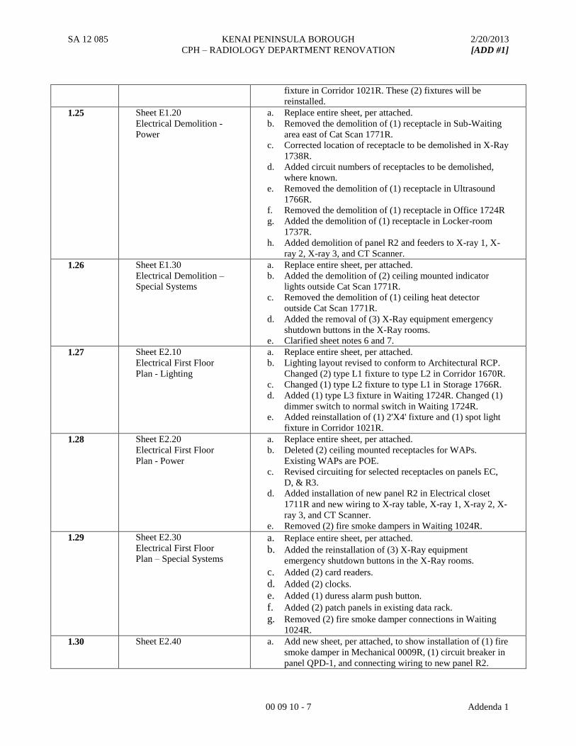
fixture in Corridor 1021R. These (2) fixtures will be
reinstalled.
1.25 Sheet E1.20
Electrical Demolition -
Power
a. Replace entire sheet, per attached.
b. Removed the demolition of (1) receptacle in Sub-Waiting
area east of Cat Scan 1771R.
c. Corrected location of receptacle to be demolished in X-Ray
1738R.
d. Added circuit numbers of receptacles to be demolished,
where known.
e. Removed the demolition of (1) receptacle in Ultrasound
1766R.
f. Removed the demolition of (1) receptacle in Office 1724R
g. Added the demolition of (1) receptacle in Locker-room
1737R.
h. Added demolition of panel R2 and feeders to X-ray 1, X-
ray 2, X-ray 3, and CT Scanner.
1.26 Sheet E1.30
Electrical Demolition –
Special Systems
a. Replace entire sheet, per attached.
b. Added the demolition of (2) ceiling mounted indicator
lights outside Cat Scan 1771R.
c. Removed the demolition of (1) ceiling heat detector
outside Cat Scan 1771R.
d. Added the removal of (3) X-Ray equipment emergency
shutdown buttons in the X-Ray rooms.
e. Clarified sheet notes 6 and 7.
1.27 Sheet E2.10
Electrical First Floor
Plan - Lighting
a. Replace entire sheet, per attached.
b. Lighting layout revised to conform to Architectural RCP.
Changed (2) type L1 fixture to type L2 in Corridor 1670R.
c. Changed (1) type L2 fixture to type L1 in Storage 1766R.
d. Added (1) type L3 fixture in Waiting 1724R. Changed (1)
dimmer switch to normal switch in Waiting 1724R.
e. Added reinstallation of (1) 2'X4' fixture and (1) spot light
fixture in Corridor 1021R.
1.28 Sheet E2.20
Electrical First Floor
Plan - Power
a. Replace entire sheet, per attached.
b. Deleted (2) ceiling mounted receptacles for WAPs.
Existing WAPs are POE.
c. Revised circuiting for selected receptacles on panels EC,
D, & R3.
d. Added installation of new panel R2 in Electrical closet
1711R and new wiring to X-ray table, X-ray 1, X-ray 2, X-
ray 3, and CT Scanner.
e. Removed (2) fire smoke dampers in Waiting 1024R.
1.29 Sheet E2.30
Electrical First Floor
Plan – Special Systems
a. Replace entire sheet, per attached.
b. Added the reinstallation of (3) X-Ray equipment
emergency shutdown buttons in the X-Ray rooms.
c. Added (2) card readers.
d. Added (2) clocks.
e. Added (1) duress alarm push button.
f. Added (2) patch panels in existing data rack.
g. Removed (2) fire smoke damper connections in Waiting
1024R.
1.30 Sheet E2.40
a. Add new sheet, per attached, to show installation of (1) fire
smoke damper in Mechanical 0009R, (1) circuit breaker in
panel QPD-1, and connecting wiring to new panel R2.

SA 12 085 KENAI PENINSULA BOROUGH 2/20/2013
CPH – RADIOLOGY DEPARTMENT RENOVATION [ADD #1]
00 09 10 - 8 Addenda 1
END OF ADDENDUM 01
PBS Engineering and Environmental 01 11 01 - 1 SUMMARY OF WORK - Central Peninsula Hospital REGULATED MATERIALS Radiation Department Renovation 19 February 2013 Soldotna, Alaska
SECTION 01 11 01
SUMARY OF WORK – REGULATED MATERIALS PART 1 - GENERAL 1.1 DESCRIPTION
A. Regulated materials requiring special handling or abatement or protection during construction include hazardous materials and dangerous wastes. The Owner has investigated the Project Site and determined that the following regulated materials could be encountered during construction and may be impacted by the Project:
1. Asbestos-containing materials (ACM) 2. Heavy metals (including lead-containing materials)
B. Survey: The Owner has included a Limited Regulated Materials Survey Report of the
Project site areas to be impacted by the Work. The Contractor shall ensure that a copy of this report is provided to all bidders and Subcontractors. A copy of this Survey must be retained and available for review on the Project site at all times throughout the duration of the Project.
C. Related Sections: This Section and the following related Construction Documents were
prepared by the Owner’s environmental consultant:
1. Section 02 82 00 “Asbestos Abatement” 2. Section 02 83 00 “Lead-Related Activities”
1.2 GENERAL REQUIREMENTS
A. Laws, Regulations, Codes and Ordinances: The Contractor shall comply with all applicable laws, regulations, codes, and ordinances concerning the impact, removal, handling, storage, disposal, monitoring and employee protection against exposure or environmental protection against pollution, related to regulated materials requiring special handling or abatement or protection during construction.
B. Supervisory Authority: The Contractor is solely and completely responsible related to the Contractor’s supervisory authority over Subcontractors and personnel performing work of this Section.
C. Access Restrictions: Access to various construction work areas by the general public,
Subcontractors, and other individuals is restricted during certain hazardous materials work sequences, as specified in the Contract Documents. The Contractor shall coordinate the Work to facilitate access by Subcontractors while enforcing work area restrictions, and shall minimize disruption to building occupants and services.
PBS Engineering and Environmental 01 11 01 - 2 SUMMARY OF WORK - Central Peninsula Hospital REGULATED MATERIALS Radiation Department Renovation 19 February 2013 Soldotna, Alaska
D. Working Hours: No hazardous materials work shall occur when building users have access
to work areas. All regulated materials work shall be scheduled to occur in accordance with schedule requirements outlined elsewhere in the Contract Documents, and when work areas have been vacated by building users.
E. Emergency Contacts: Designated qualified representatives of the Contractor and specific
hazardous materials Subcontractors are to be available on a 24-hour emergency basis for the duration of the Work. Contact information shall be provided to the Owner’s Representative for inclusion in the Project emergency contact list.
F. Submittals: Contractor shall review the scope of work requirements outlined in the Contract
Documents and shall submit, and require all Subcontractors performing the work of handling or disposing of any regulated materials to submit, pertinent information required by the Contract Documents.
G. Regulated Materials - Waste Manifests: Prior to Final Completion, the Contractor shall
submit to the Owner copies of all transportation and disposal manifests, including signed landfill receipts and chain-of-custody, for all regulated wastes disposed of by the Contractor during the course of the Project.
1.4 SPECIAL CONDITIONS – Not Used. PART 2 – PRODUCTS (Not Used) PART 3 – EXECUTION (Not Used)
END OF SECTION
PBS Engineering and Environmental 02 80 00 - 1 FACILITIES REMEDIATION Central Peninsula Hospital 19 February 2013 Radiation Department Renovation Soldotna, Alaska
SECTION 02 80 00 FACILITIES REMEDIATION PART 1 - GENERAL
1.1 DESCRIPTION OF WORK
A. The Contractor shall perform all planning, administration, execution, and cleaning necessary to safely remove, dispose and/or handle the regulated materials listed within this Section.
1.2 WORK INCLUDED
A. Asbestos:
1. Asbestos abatement (removal and disposal) is included in this Project.
a. Contractor shall coordinate with Owner, other trades, furnish all labor, materials, equipment, services, notifications, and insurance - specifically covering the handling and transportation of Asbestos-Containing Materials (ACM) that is specified, shown, or reasonably implied for the removal and disposal, or impact, of asbestos-containing materials according to Section 02 82 00 – Asbestos Abatement.
b. Asbestos abatement includes the removal and disposal of the following:
200 square feet of asbestos-containing floor tile and mastic. The substrate is concrete.
B. Lead/Metals:
1. Disturbance of Lead/Metals is anticipated as part of the project work;
2. Lead abatement includes the removal and disposal of the following:
500 square feet of lead sheeting concealed inside walls, doors,
and door frames.
3. It is anticipated that disposal of the lead waste stream generated by the Work will be either recycled or disposed of in accordance with 40 CFR Part 261(RCRA).
4. Provide submittal information outlined in Section 02 83 00.
PBS Engineering and Environmental 02 80 00 - 2 FACILITIES REMEDIATION Central Peninsula Hospital 19 February 2013 Radiation Department Renovation Soldotna, Alaska
1.3 WORK NOT INCLUDED
Air monitoring to be performed by the Owner as described in Section 02 82 00 – Asbestos Abatement.
PART 2 - PRODUCTS
2.1 MATERIALS – Not used
2.2 EQUIPMENT – Not used
PART 3 - EXECUTION 3.1 ASBESTOS - Refer to Specification Section 02 82 00.
3.2 LEAD /METALS-CONTAINING PAINT, COATINGS, AND MATERIALS - Refer to
Specification Section 02 83 00
END OF SECTION
PBS Engineering and Environmental 02 83 00 - 1 LEAD-RELATED ACTIVITIES Central Peninsula Hospital 19 February 2013 Radiation Department Renovation Soldotna, Alaska
SECTION 02 83 00
LEAD-RELATED ACTIVITIES PART 1 GENERAL
1.1 SUMMARY OF WORK
A. General work items include, but are not limited to:
1. Compliance: Activities requiring compliance with this Section include the removal of lead sheeting. Refer to Section 02 80 00 for information regarding lead-containing products in areas of the Work.
2. Waste Disposal: It is anticipated that lead sheets removed during this project will be recycled.
1.2 RELATED SECTIONS A. Work performed under this specification section is governed by related specification sections,
plans or drawings not limited to the following:
Division 0, Contract Requirements; Division 1, General Requirements:
1.3 SUBMITTALS A. Submit five bound sets the following "Pre-Work Submittals" prior to start of work. The Work
may not proceed until complete Pre-Work Submittal package has been reviewed and approved by the Environmental Consultant. Allow ten days for Owner review. 1. Lead/Metals Compliance Program: Submit a site-specific lead compliance program in
accordance with OSHA 1926.62 and this section. The plan shall be developed and implemented to provide engineering, work practice and administrative controls to reduce and maintain employee exposure to lead at or below the permissible exposure limit. The plan will include at a minimum task-specific descriptions of activities; engineering controls; personnel; procedures; method of compliance; technology used to meet compliance; detailed schedule; work practice program; administrative controls and other relevant information. Implementation of work practices not described in the Lead Compliance Plan will not be permitted until an amendment to the submittal is reviewed by the Environmental Consultant and Owner.
2. Medical Program: Submit written proof medical exam program complies with OSHA Lead
Regulations 29 CFR 1910.2 and 1926.62. Initial medical surveillance consisting of biological monitoring in the form of blood sampling and analysis for lead and zinc protoporphyrin levels shall be submitted for each employee anticipated to be occupationally exposed to lead at or above the action level.
3. Worker Training Program: Submit written proof indicating that all employees impacting
lead/metals-containing materials have received training per 29 CFR 1926. Proof shall include
PBS Engineering and Environmental 02 83 00 - 2 LEAD-RELATED ACTIVITIES Central Peninsula Hospital 19 February 2013 Radiation Department Renovation Soldotna, Alaska
a signature from the Contractor's Principal indicating that all employees performing lead related activities have completed such a program.
4. Respirator Program: Submit written proof indicating respirator program complies with all
parts of OSHA Lead Regulations 29 CFR 1910.134 and 1926.62. 5. Waste Stream Calculations: Submit a detailed breakdown of waste stream constituents and
associated volumetric calculations for review by the Environmental Consultant to determine the need for additional waste stream calculation or further waste characterization.
B. Final Submittals:
1. Project Record Documents: Provide record of lead control activities including disposition of
each type of lead-containing item and products removed from the site.
1.5 SUBCONTRACTORS
A. Subcontractors employed by the Contractor shall be bound to all the work and safety standards specified. Subcontractor's personnel shall meet requirements as specified, and shall be supervised by the Contractor during performance of this work.
1.6 LIABILITY
A. The Contractor is an independent contractor and not an employee of the Owner, Architect or Environmental Consultant. The Owner and the Environmental Consultant shall have no liability to the Contractor or any third persons for Contractor's failure to faithfully perform and follow the provisions of these Specifications and the requirements of the governing agencies. Notwith-standing the failure of the Owner or the Environmental Consultant to discover a violation by the Contractor of any of the provisions of these Specifications, or to require the Contractor to fully perform and follow any of them, such failure shall not constitute a waiver of any of the require-ments of these Specifications which shall remain fully binding upon the Contractor.
PART 2 - PRODUCTS 2.1 PROTECTIVE CLOTHING AND EQUIPMENT
A. Personnel Protective Equipment and materials for Lead-related activities shall be provided per OSHA 1926.62.
PART 3 - EXECUTION 3.1 WORK PRACTICES
A. Restrictions:
1. Use of mechanical methods including, but not limited to power sanding, grinding, sand-
blasting, etc. shall be performed within a negative pressure enclosure (NPE) pending approval of negative exposure assessment by the Owner.
PBS Engineering and Environmental 02 83 00 - 3 LEAD-RELATED ACTIVITIES Central Peninsula Hospital 19 February 2013 Radiation Department Renovation Soldotna, Alaska
B. Negative Exposure Assessment: The Contractor may waive the requirement of a negative pressure enclosure when using mechanical methods upon approval by the Environmental Consultant of data indicating a negative exposure assessment has been completed per OSHA 1926.62-(d) and paragraph 1.6, Air Monitoring. The Contractor shall allow 48-hours for review of such data.
C. Housekeeping: Maintain all surfaces as free as practicable of accumulations of lead and perform
clean-up and wet wipe down of work areas as necessary according to OSHA 1926.62-(h).
D. Work Practices:
1. Set-up Activities: Prior to impact of lead sheeting, Contractor shall cover the ground below the work area with 6-mil plastic sheeting or equivalent. The drop-sheeting shall extend outward a minimum of 6 feet from the location of item(s) being removed. Any tears that occur in the drop-sheeting shall be immediately repaired with duct tape or other acceptable seal. Debris shall be collected with a HEPA vacuum to avoid escape from the drop-sheeting. Wash water shall be retained on the drop-sheeting and removed by mops or wet/dry vacuums. Any non-recyclable debris and water shall be placed in storage drums for testing prior to disposal. See paragraph 3.1-E for testing requirements.
2. Perform work impacting lead-containing items in accordance with approved lead work plan.
Use procedures and equipment required to limit occupational and environmental exposure to lead when lead-sheeting is impacted. The procedures employed by the Contractor shall not create the potential for contaminating surrounding areas or materials with lead-containing dust. Dust generation shall be minimized at all times.
3. At completion of the above operations, HEPA vacuum drop-sheeting to remove any paint
particles or debris. Wet-wipe or mop plastic sheeting to remove all dust. E. Debris Testing
1. Debris Testing: A representative sample from debris shall be collected for TCLP testing by the Contractor. The method/location of general debris disposal will be established by test results (less than 5 parts per million). See paragraph 3.1-F for disposal requirements.
F. Disposal Procedures:
1. Waste characterization of the anticipated general waste stream will be performed by the
Contactor as necessary. Results of such characterization will be provided to the Owner as appropriate. The Owner anticipates that lead sheeting can be recycled.
END OF SECTION

SA 12 085 KENAI PENINSULA BOROUGHCPH - RADIOLOGY DEPARTMENT RENOVATION
2/1/2013
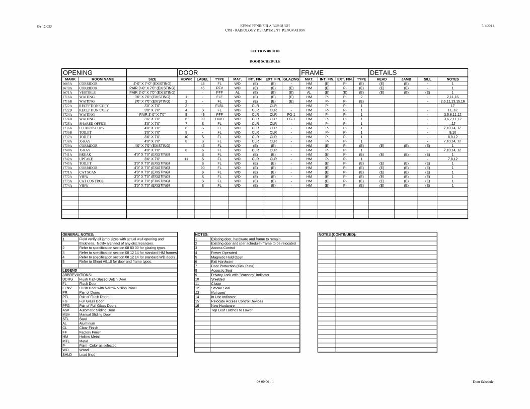
OPENING DOOR FRAME DETAILSMARK ROOM NAME SIZE HDWR LABEL TYPE MAT. INT. FIN. EXT. FIN. GLAZING MAT. INT. FIN. EXT. FIN. TYPE HEAD JAMB SILL NOTES
1663A CORRIDOR 4'-0" X 7'-0" (EXISTING) 45 FL WD (E) (E) - HM (E) P- (E) (E) (E) - 1
1670A CORRIDOR PAIR 3'-0" X 7'0" (EXISTING) 45 PFV WD (E) (E) (E) HM (E) P- (E) (E) (E) - 1
1671A VESTIBLE PAIR 3'-0" X 7'0" (EXISTING) - PFF AL (E) (E) (E) AL (E) (E) (E) (E) (E) (E) 1
1716A WAITING 3'0" X 7'0" (EXISTING) 1 - FLF WD (E) (E) (E) HM P- P- 2 - 2,11,16
1716B WAITING 3'0" X 7'0" (EXISTING) 2 - FL WD (E) (E) (E) HM P- P- (E) - 2,6,11,13,15,16
1722A RECEPTION/COPY 3'0" X 7'0" 3 - FLBL WD CLR CLR - HM P- P- 1 17
1722B RECEPTION/COPY 3'0" X 7'0" 4 S FL WD CLR CLR - HM P- P- 1 - 11, 12
1724A WAITING PAIR 3'-0" X 7'0" 5 45 PFF WD CLR CLR FG-1 HM P- P- 1 - 3,5,6,11,12
1724B WAITING 3'6" X 7'0" 6 90 FNV1 WD CLR CLR FG-1 HM P- P- 1 - 3,6,7,11,12
1725A SHARED OFFICE 3'0" X 7'0" 7 S FL WD CLR CLR - HM P- P- 1 - . 12
1736A FLUOROSCOPY 4'0" X 7'0" 8 S FL WD CLR CLR - HM P- P- 1 - 7,10,14, 12
1736B TOILET 3'0" X 7'0" 9 - FL WD CLR CLR - HM P- P- 1 - 9,10
1737A TOILET 3'6" X 7'0" 10 S FL WD CLR CLR - HM P- P- 1 - 8,9,12
1738A X-RAY 4'0" X 7'0" 8 S FL WD CLR CLR - HM P- P- 1 - 7,10,14, 12
1739A CORRIDOR 4'0" X 7'0" (EXISTING) 45 FL WD (E) (E) - HM (E) P- (E) (E) (E) (E) 1
1740A X-RAY 4'0" X 7'0" 8 S FL WD CLR CLR - HM P- P- 1 - 7,10,14, 12
1741A BREAK 4'0" X 7'0" (EXISTING) S FL WD (E) (E) - HM (E) P- (E) (E) (E) (E) 1
1742A UPTAKE 3'6" X 7'0" 11 S FL WD CLR CLR - HM P- P- 1 - 7,8,12
1743A TOILET 3'0" X 7'0" (EXISTING) S FL WD (E) (E) - HM (E) P- (E) (E) (E) (E) 1
1770A CORRIDOR 4'0" X 7'0" (EXISTING) 90 FL WD (E) (E) - HM (E) P- (E) (E) (E) (E) 1
1771A CAT SCAN 4'0" X 7'0" (EXISTING) S FL WD (E) (E) - HM (E) P- (E) (E) (E) (E) 1
1772A VIEW 3'0" X 7'0" (EXISTING) S FL WD (E) (E) - HM (E) P- (E) (E) (E) (E) 1
1773A CAT CONTROL 3'0" X 7'0" (EXISTING) S FL WD (E) (E) - HM (E) P- (E) (E) (E) (E) 1
1774A VIEW 3'0" X 7'0" (EXISTING) S FL WD (E) (E) - HM (E) P- (E) (E) (E) (E) 1
GENERAL NOTES: NOTES:
1 1
2
2 3
3 Refer to specification section 08 12 14 for standard HM frames 4
4 Refer to specification section 08 12 14 for standard WD doors 5
5 6
7
LEGEND 8
ABBREVIATIONS: 9
DDHG Flush Half-Glazed Dutch Door 10
FL Flush Door 11
FLNV Flush Door with Narrow Vision Panel 12
PR Pair of Doors 13
PFL Pair of Flush Doors 14
FG Full Glass Door 15 Relocate Access Control Devices
PFG Pair of Full Glass Doors 16 New Hardware
AS# Automatic Sliding Door 17
MS# Manual Sliding Door
STL Steel
AL Aluminum
CL Clear Finish
FF Factory Finish
HM Hollow Metal
MTL Metal
P- Paint- Color as selected
WD Wood
SHLD Lead lined
SECTION 08 00 00
DOOR SCHEDULE
NOTES (CONTINUED):
Field verify all jamb sizes with actual wall opening and
Refer to specification section 08 80 00 for glazing types. Access Control
Existing door, hardware and frame to remain.
Existing door and (per schedule) frame to be relocatedthickness. Notify architect of any discrepancies.
Power Operated
Refer to Sheet A9.10 for door and frame types.
Closer
Magnetic Hold Open
Privacy Lock with "Vacancy" indicator
Door Protection (Kick Plate)
Not used
Acoustic Seal
Shielded
Exit Hardware
Smoke Seal
In Use Indicator
Top Leaf Latches to Lower
08 00 00 - 1 Door Schedule

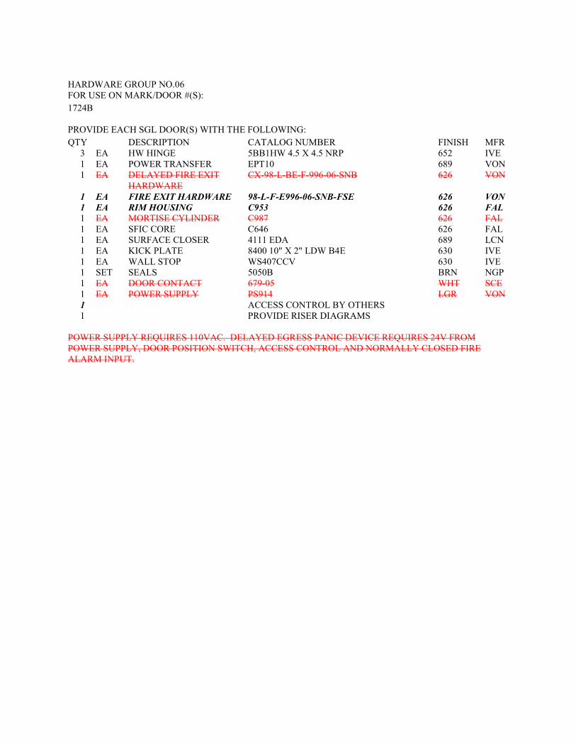
HARDWARE GROUP NO.06 FOR USE ON MARK/DOOR #(S): 1724B PROVIDE EACH SGL DOOR(S) WITH THE FOLLOWING: QTY DESCRIPTION CATALOG NUMBER FINISH MFR
3 EA HW HINGE 5BB1HW 4.5 X 4.5 NRP 652 IVE 1 EA POWER TRANSFER EPT10 689 VON 1 EA DELAYED FIRE EXIT
HARDWARE CX-98-L-BE-F-996-06-SNB 626 VON
1 EA FIRE EXIT HARDWARE 98-L-F-E996-06-SNB-FSE 626 VON 1 EA RIM HOUSING C953 626 FAL 1 EA MORTISE CYLINDER C987 626 FAL 1 EA SFIC CORE C646 626 FAL 1 EA SURFACE CLOSER 4111 EDA 689 LCN 1 EA KICK PLATE 8400 10" X 2" LDW B4E 630 IVE 1 EA WALL STOP WS407CCV 630 IVE 1 SET SEALS 5050B BRN NGP 1 EA DOOR CONTACT 679-05 WHT SCE 1 EA POWER SUPPLY PS914 LGR VON 1 ACCESS CONTROL BY OTHERS 1 PROVIDE RISER DIAGRAMS
POWER SUPPLY REQUIRES 110VAC. DELAYED EGRESS PANIC DEVICE REQUIRES 24V FROM POWER SUPPLY, DOOR POSITION SWITCH, ACCESS CONTROL AND NORMALLY CLOSED FIRE ALARM INPUT.

SA 12 085 KENAI PENINSULA BOROUGH 2/1/2013
CPH – RADIOLOGY DEPARTMENT RENOVATION ADD #1 2/20/13
23 00 00 - 11 General Mechanical Work
C. Guarantee:
1. All work performed under this Contract shall be guaranteed against faulty and improper
materials and workmanship for a period of one year from the date of final acceptance by
the Owner, except that where guarantees or warranties for longer terms are specified
herein, such longer term shall apply, and this Contractor, at no additional cost to the
Owner, shall promptly correct any deficiencies which occur during the guarantee period,
all to the satisfaction of the Owner. This Contractor shall require similar guarantees from
its subcontractors.
2. All equipment and installation shall be guaranteed by the Contractor to be in compliance
with OSHA regulations.
1.16 CONTROLS
A. Scope of controls work is documented in the project mechanical drawings. The project will
relocate and replace components in the existing control system.
B. Provide UL listed equipment compatible with the existing control systems. All equipment
necessary for integration of new and relocated components are to be provided by the controls
contractor. Provide new input and output devices as required. The existing control sequences
are to be used for the relocated and replaced components. Installation shall not adversely affect
the existing control system.
C. Wiring: Comply with the requirements of Division 26.
D. Control Contractor to demonstrate system operation to Owner's representative and
Commissioning Agent at project completion.
PART 2 PRODUCTS
Not Applicable.
PART 3 EXECUTION
Not Applicable.
END OF SECTION

SA 12 085 KENAI PENINSULA BOROUGH 2/1/2013 CPH – RADIOLOGY DEPARTMENT RENOVATION [ADD #1 2/20/13]
26 24 16 - 1 Panelboards
SECTION 26 24 16
PANELBOARDS
PART 1 GENERAL
1.1 RELATED DOCUMENTS
A. Drawings and general provisions of the Contract, including General and Supplementary Condi-tions and Division 01 Specification Sections, apply to this Section.
1.2 SUBMITTALS
A. Product Data: For each type of panelboard, overcurrent protective device, transient voltage sup-pression device, accessory, and component indicated. Include dimensions and manufacturers' technical data on features, performance, electrical characteristics, ratings, and finishes.
B. Shop Drawings: For each panelboard and related equipment. 1. Dimensioned plans, elevations, sections, and details. Show tabulations of installed de-
vices, equipment features, and ratings. Include the following: a. Enclosure types and details for types other than NEMA 250, Type 1. b. Bus configuration, current, and voltage ratings. c. Short-circuit current rating of panelboards and overcurrent protective devices. d. UL listing for series rating of installed devices. e. Features, characteristics, ratings, and factory settings of individual overcurrent
protective devices and auxiliary components. 2. Wiring Diagrams: Power, signal, and control wiring.
C. Panelboard Schedules: For installation in panelboards.
D. Interruption of Existing Electric Service: Do not interrupt electric service to facilities occupied by Owner or others unless permitted under the following conditions and then only after arranging to provide temporary electric service according to requirements indicated: 1. Notify Architect no fewer than two days in advance of proposed interruption of electrical
service. 2. Do not proceed with interruption of electrical service without Architect's written permis-
sion.
PART 2 PRODUCTS
2.1 MANUFACTURERS
A. Manufacturers: 1. Transient Voltage Suppression Panelboards: 2. GE, or approved equal.
2.2 MANUFACTURED UNITS
A. Enclosures: 1. NEMA 250, Type 1 2. Hinged Front Cover: Door within door. 3. Finish: Manufacturer's standard enamel finish over corrosion-resistant treatment or pri-
mer coat.
SA 12 085 KENAI PENINSULA BOROUGH 2/1/2013 CPH – RADIOLOGY DEPARTMENT RENOVATION [ADD #1 2/20/13]
26 24 16 - 2 Panelboards
4. Directory Card: With transparent protective cover, mounted in metal frame, inside pa-nelboard door.
B. Phase and Ground Buses: 1. Material: Hard-drawn copper, 98 percent conductivity. 2. Equipment Ground Bus: Adequate for feeder and branch-circuit equipment ground con-
ductors; bonded to box.
C. Conductor Connectors: Suitable for use with conductor material. 1. Main and Neutral Lugs: Compression type. 2. Ground Lugs and Bus Configured Terminators: Compression type. 3. Feed-Through Lugs: Compression type suitable for use with conductor material. Locate
at opposite end of bus from incoming lugs or main device.
D. Future Devices: Mounting brackets, bus connections, and necessary appurtenances required for future installation of devices.
2.3 PANELBOARD SHORT-CIRCUIT RATING
A. Fully rated to interrupt symmetrical short-circuit current available at terminals.
2.4 TRANSIENT VOLTAGE SUPPRESSION PANELBOARDS
A. Doors: Secured with vault-type latch with tumbler lock; keyed alike.
B. Main Overcurrent Devices: Thermal-magnetic circuit breaker.
C. Branch Overcurrent Protective Devices: Bolt-on circuit breakers.
D. Bus: Copper phase and neutral buses; 200 percent capacity neutral bus and lugs.
E. Transient Voltage Suppression Device: IEEE C62.41, integrally mounted, plug-in-style, solid-state, parallel-connected, sine-wave tracking suppression and filtering modules. 1. Minimum Single-Impulse Current Ratings:
a. Line to Neutral: 100,000 A. b. Line to Ground: 100,000 A. c. Neutral to Ground: 50,000 A.
2. Protection modes shall be as follows: a. Line to neutral. b. Line to ground. c. Neutral to ground.
3. EMI/RFI Noise Attenuation Using 50-ohm Insertion Loss Test: 55 dB at 100 kHz. 4. Maximum Category C Combination Wave Clamping Voltage: 600 V, line to neutral and
line to ground on 120/208 V systems. 5. Maximum UL 1449 Clamping Levels: 400 V, line to neutral and line to ground on
120/208 V, 800 V, line to neutral and line to ground on 277/480 V systems. 6. Withstand Capabilities: 3000 Category C surges with less than 5 percent change in
clamping voltage.
2.5 OVERCURRENT PROTECTIVE DEVICES
A. Molded-Case Circuit Breaker: UL 489, with interrupting capacity to meet available fault currents. 1. Thermal-Magnetic Circuit Breakers: Inverse time-current element for low-level over-
loads, and instantaneous magnetic trip element for short circuits.
SA 12 085 KENAI PENINSULA BOROUGH 2/1/2013 CPH – RADIOLOGY DEPARTMENT RENOVATION [ADD #1 2/20/13]
26 24 16 - 3 Panelboards
2.6 SPACE FOR FUTURE CIRCUIT BREAKRS OR FUSED SWITCHES
A. Provide as indicated on the drawings. Spaces shall be completely equipped for the future addition of a circuit breaker or fused switch, including all mounting hardware and buss connections. Unless otherwise noted, spaces shall be sized to accommodate the following future circuit breaker or fused switch.
PART 3 EXECUTION
3.1 INSTALLATION
A. Comply with mounting and anchoring requirements specified in Division 26 Section "Vibration and Seismic Controls for Electrical Systems."
B. Mount top of trim 74 inches above finished floor, unless otherwise indicated.
C. Mount plumb and rigid without distortion of box. Mount recessed panelboards with fronts un-iformly flush with wall finish.
D. Install overcurrent protective devices and controllers. 1. Set field-adjustable switches and circuit-breaker trip ranges.
E. Install filler plates in unused spaces.
F. Stub four 1-inch empty conduits from panelboard into accessible ceiling space or space designated to be ceiling space in the future. Stub four 1-inch empty conduits into raised floor space or below slab not on grade.
G. Arrange conductors in gutters into groups and bundle and wrap with wire ties.
3.2 IDENTIFICATION
A. Identify field-installed conductors, interconnecting wiring, and components; provide warning signs as specified in Division 26 Section "Identification for Electrical Systems."
B. Create a directory to indicate installed circuit loads. Obtain approval before installing. Use a computer or typewriter to create directory; handwritten directories are not acceptable.
C. Panelboard Nameplates: Label each panelboard with engraved metal or laminated-plastic namep-late mounted with corrosion-resistant screws.
END OF SECTION

SA 12 085 KENAI PENINSULA BOROUGH 2/1/2013 CPH – RADIOLOGY DEPARTMENT RENOVATION [ADD #1 2/20/13]
27 53 13 - 1 Clock System
SECTION 27 53 13
CLOCK SYSTEM
PART 1 GENERAL
1.1 SECTION INCLUDES
A. Provide portable, analog, battery powered clocks that are compatible with the existing Primex GPS clock synchronization system, as indicated on the drawings.
1.2 REGULATORY REQUIREMENTS
A. Equipment and components furnished shall be of manufacturer’s latest model.
B. Receiver shall comply with Part 90 of FCC rules as follows: 1. This device may not cause harmful interference. 2. This device must accept interference received, including interference that may cause
undesired operation. 3. Transmitter frequency shall be governed by FCC Part 90.35. 4. Transmitter output power shall be governed by FCC Part 90 257 (b).
C. System shall be installed in compliance with local and state authorities having jurisdiction.
1.3 SUBMITTALS
A. Product Data: Submit complete catalog data for each component, describing physical characteristics and method of installation. Submit brochure showing available colors and finishes of clocks.
B. Manufacturer's Instructions: Submit complete installation, set-up and maintenance instructions.
1.4 DELIVERY STORAGE AND HANDLING
A. Deliver all components to the site in the manufacturer's original packaging. Packaging shall contain manufacturer's name and address, product identification number, and other related information.
B. Store equipment in finished building, unopened containers until ready for installation.
1.5 SYSTEM STARTUP
A. At completion of installation and prior to final acceptance, turn on the equipment; ensure that all clocks are functioning.
1.6 WARRANTY
A. All components shall have a 1 year warranty.
SA 12 085 KENAI PENINSULA BOROUGH 2/1/2013 CPH – RADIOLOGY DEPARTMENT RENOVATION [ADD #1 2/20/13]
27 53 13 - 2 Clock System
PART 2 PRODUCTS
2.1 SEQUENCE OF OPERATION
A. Analog Clock Operation: 1. Apply power or insert batteries. Follow set up procedures detailed in manufacturer’s
instructions. 2. After initial setup, the clock will shut off the receiver. Six times each day, the
microprocessor will activate the receiver and starting with the stored channel, it will again look for a valid time signal. If necessary, the clocks will resynchronize to the correct time.
3. If the clock has not decoded a valid time signal for a pre-determined number of days, it will go to a step mode. Non signal reception can be caused by low battery voltage. If this occurs, replace the batteries.
2.2 EQUIPMENT
A. Traditional Analog Clocks (battery): Analog clocks shall be wall mounted. Clocks shall have polycarbonate frame and polycarbonate lens. Face shall be white. Hour and minute hands shall be black. 1. Primex Part No. 14163 or approved equal. 2. 16 Inch Diameter Analog Clock. 3. Analog clocks shall be battery-operated, and shall have minimum 5-year battery life. 4. Analog clocks shall be capable of automatically adjusting for Daylight Saving Time. An
on-off switch located on the transmitter shall disable this function if desired. 5. Time shall be automatically updated from the transmitter 6 times per day. 6. Analog clocks shall remember the time during changing of batteries. 7. Provide two alkaline batteries of the required size, per clock. 8. Analog clock receivers shall be as follows:
a. Receiver Sensitivity: >-110 dBm. b. Receiver Power: Alkaline batteries c. Antenna Type: Internal. d. Antenna Gain: -7 dBd.
9. If the transmitter stops transmitting valid time signals due to power failure, the clocks will continue to function as accurate quartz clocks until a valid time signal is decoded. If signal transmission is not restored after 48 hours, the second hand will “five step” as a visual indicator that the signal has been lost. Should the clocks lose power and signal, the clocks will not function.
PART 3 EXECUTION
3.1 EXAMINATION
A. Verify that construction is complete in spaces to receive equipment and that rooms are clean and dry.
B. Clocks shall not be installed until painting and other finish work in each room is complete.
3.2 INSTALLATION
A. Analog Clocks (battery): Perform the following operations with each clock: 1. Install batteries. 2. Set clock to correct time in accordance with manufacturer's instructions.
SA 12 085 KENAI PENINSULA BOROUGH 2/1/2013 CPH – RADIOLOGY DEPARTMENT RENOVATION [ADD #1 2/20/13]
27 53 13 - 3 Clock System
3. Observe analog clock until valid signals are received and analog clock adjusts itself to correct time.
4. Install the analog clock on the wall in the indicated location, plumb, level and tight against the wall. Attach using clock-lock hanging method and suitable fasteners as approved by clock manufacturer.
3.3 ADJUSTING
A. Prior to final acceptance, inspect each clock, adjust as required, and replace parts which are found defective.
3.4 CLEANING
A. Prior to final acceptance, clean exposed surfaces of clocks, using cleaning methods recommended by clock manufacturer. Remove temporary labels from clock faces. Do not remove labels from backs of clocks.
3.5 PROTECTION
A. Protect finished installation until final acceptance of the project.
3.6 TESTING
A. All devices must be tested at their operational location under normal operational conditions to assure reception of signal.
END OF SECTION

SA 12 085 KENAI PENINSULA BOROUGH 2/01/13 CPH – RADIOLOGY DEPARTMENT RENOVATION [ADD #1 2/20/13]
28 16 01 - 1 Security Access Control System
SECTION 28 16 01
SECURITY ACCESS CONTROL SYSTEM
PART 1 GENERAL
1.1 DESCRIPTION
A. Install additional card readers and associated door harware and duress alarm push button to existing security system.
1.2 RELATED DOCUMENTS
A. Drawings and general provisions of the Contract, including General and Supplementary Conditions and Division 01 Specification Sections, apply to this Section.
1.3 SUBMITTALS
A. Product Data: For each type of product indicated.
B. Shop Drawings: Device installation drawings and wiring diagrams,
PART 2 PRODUCTS
2.1 MANUFACTURERS
A. All equipment installed shall be fully compatible with the existing security access control system.
B. The security contractor shall provide the latest product model at the time of installation.
2.2 MATERIALS
A. All products and materials are to be new and free of defects, damage and corrosion. All materials shall be in compliance to all applicable codes and designed specifically for the function intended.
B. Wire and Cable: All wiring and cabling shall be per the manufacturers' recommendations. Unauthorized deviations may result in the voiding of the manufacturer's warranty.
2.3 CARD READERS
A. Black, low profile, surface mounted RFID reader with LED indicator light compatible with existing access control system.
2.4 DURESS ALARM BUTTON
A. Stationary, low profile, surface mounted momentary push button light compatible with existing security system.
2.5 WARRANTY
A. All products and materials must include a manufacturer’s minimum one-year warranty from date of shipment. The warranty shall include material and labor to repair faulty equipment.
SA 12 085 KENAI PENINSULA BOROUGH 2/01/13 CPH – RADIOLOGY DEPARTMENT RENOVATION [ADD #1 2/20/13]
28 16 01 - 2 Security Access Control System
2.6 QUALITY ASSURANCE
A. Tests: After installation, and before termination, all wiring shall be checked and tested to insure there are no grounds, opens or shorts on any conductors or shields. The security contractor shall maintain a complete log of all such quality assurance tests and make them available for inspection by the owner at any time during the construction phase. At the completion of the installation all test results shall become part of the maintenance documentation.
B. Inspection: 1. The security contractor shall carry out the inspection requirements of the contract and
shall provide the owner with documentation to the effect that off-site work is being properly fabricated, and in accordance with the contract documents.
2. The security contractor shall notify the owner sufficiently in advance of the time when quality control tests are to be performed so that the owner or their designee may witness such tests, if desired. The presence or absence of the owner from these tests shall not relieve the security contractor from completing the tests in accordance with the contract documents. Security contractors QA documentation and practices shall be subject to an engineer’s inspection at any time.
PART 3 EXECUTION
3.1 INSTRUCTION FOR OWNER’S PERSONNEL
A. Scope: Following initial operation of all intercom equipment and prior to final acceptance, conduct demonstrations of equipment operation and instruction periods for the Owner's representatives. Refer to section 01 79 00 for general requirements and minimum training duration.
END OF SECTION
SA 12 085 KENAI PENINSULA BOROUGH 2/1/2013 CPH – RADIOLOGY DEPARTMENT RENOVATION
28 31 11 - 1 Fire-Alarm System
SECTION 28 31 11
FIRE-ALARM SYSTEM
PART 1 GENERAL
1.1 SCOPE
A. Provide modifications to the existing fire alarm system, as indicated on the drawings.
1.2 RELATED DOCUMENTS
A. Drawings and general provisions of the Contract, including General and Supplementary Condi-tions and Division 01 Specification Sections, apply to this Section.
1.3 DEFINITIONS
A. LED: Light-emitting diode.
B. NICET: National Institute for Certification in Engineering Technologies.
1.4 SUBMITTALS
A. Product Data: For each type of product indicated.
B. Shop Drawings: For fire-alarm system. Include plans, elevations, sections, details, and attach-ments to other work. 1. Comply with recommendations in the "Documentation" Section of the "Fundamentals of
Fire Alarm Systems" Chapter in NFPA 72. 2. Include floor plans to indicate final outlet locations showing address of each addressable
device. Show size and route of cable and conduits.
1.5 PROJECT CONDITIONS
A. Interruption of Existing Fire-Alarm Service: Do not interrupt fire-alarm service to facilities occu-pied by Owner or others unless permitted under the following conditions and then only after ar-ranging to provide temporary guard service according to requirements indicated: 1. Notify Owner no fewer than two days in advance of proposed interruption of fire-alarm
service. 2. Do not proceed with interruption of fire-alarm service without Owner's written permis-
sion. 3. .
PART 2 PRODUCTS
2.1 MANUAL FIRE-ALARM BOXES
A. General Requirements for Manual Fire-Alarm Boxes: Comply with UL 38. Boxes shall be fi-nished in red with molded, raised-letter operating instructions in contrasting color; shall show vis-ible indication of operation; and shall be mounted on recessed outlet box. If indicated as surface mounted, provide manufacturer's surface back box.
SA 12 085 KENAI PENINSULA BOROUGH 2/1/2013 CPH – RADIOLOGY DEPARTMENT RENOVATION
28 31 11 - 2 Fire-Alarm System
1. Double-action mechanism requiring two actions to initiate an alarm, pull-lever type; with integral addressable module arranged to communicate manual-station status (normal, alarm, or trouble) to fire-alarm control unit.
2. Station Reset: Key- or wrench-operated switch. 3. Indoor Protective Shield: Factory-fabricated clear plastic enclosure hinged at the top to
permit lifting for access to initiate an alarm. Lifting the cover actuates an integral bat-tery-powered audible horn intended to discourage false-alarm operation.
4. Weatherproof Protective Shield: Factory-fabricated clear plastic enclosure hinged at the top to permit lifting for access to initiate an alarm.
2.2 SYSTEM SMOKE DETECTORS
A. General Requirements for System Smoke Detectors: 1. Comply with UL 268; operating at 24-V dc, nominal. 2. Detectors shall be four-wire type. 3. Integral Addressable Module: Arranged to communicate detector status (normal, alarm,
or trouble) to fire-alarm control unit. 4. Base Mounting: Detector and associated electronic components shall be mounted in a
twist-lock module that connects to a fixed base. Provide terminals in the fixed base for connection to building wiring.
5. Self-Restoring: Detectors do not require resetting or readjustment after actuation to re-store them to normal operation.
6. Integral Visual-Indicating Light: LED type indicating detector has operated and power-on status.
7. Remote Control: Unless otherwise indicated, detectors shall be analog-addressable type, individually monitored at fire-alarm control unit for calibration, sensitivity, and alarm condition and individually adjustable for sensitivity by fire-alarm control unit. a. Rate-of-rise temperature characteristic shall be selectable at fire-alarm control
unit for 15 or 20 deg F per minute. b. Fixed-temperature sensing shall be independent of rate-of-rise sensing and shall
be settable at fire-alarm control unit to operate at 135 or 155 deg F. c. Provide multiple levels of detection sensitivity for each sensor.
B. Ionization Smoke Detector: 1. Detector address shall be accessible from fire-alarm control unit and shall be able to iden-
tify the detector's location within the system and its sensitivity setting. 2. An operator at fire-alarm control unit, having the designated access level, shall be able to
manually access the following for each detector: a. Primary status. b. Device type. c. Present average value. d. Present sensitivity selected. e. Sensor range (normal, dirty, etc.).
C. Duct Smoke Detectors: Photoelectric type complying with UL 268A. 1. Detector address shall be accessible from fire-alarm control unit and shall be able to iden-
tify the detector's location within the system and its sensitivity setting. 2. An operator at fire-alarm control unit, having the designated access level, shall be able to
manually access the following for each detector: a. Primary status. b. Device type. c. Present average value. d. Present sensitivity selected. e. Sensor range (normal, dirty, etc.).
3. Weatherproof Duct Housing Enclosure: NEMA 250, Type 4X; NRTL listed for use with the supplied detector.
SA 12 085 KENAI PENINSULA BOROUGH 2/1/2013 CPH – RADIOLOGY DEPARTMENT RENOVATION
28 31 11 - 3 Fire-Alarm System
4. Each sensor shall have multiple levels of detection sensitivity. 5. Sampling Tubes: Design and dimensions as recommended by manufacturer for specific
duct size, air velocity, and installation conditions where applied. 6. Relay Fan Shutdown: Rated to interrupt fan motor-control circuit.
2.3 HEAT DETECTORS
A. General Requirements for Heat Detectors: Comply with UL 521.
B. Heat Detector, Combination Type: Actuated by either a fixed temperature of 135 deg F or a rate of rise that exceeds 15 deg F per minute unless otherwise indicated. 1. Mounting: Twist-lock base interchangeable with smoke-detector bases. 2. Integral Addressable Module: Arranged to communicate detector status (normal, alarm,
or trouble) to fire-alarm control unit.
2.4 NOTIFICATION APPLIANCES
A. General Requirements for Notification Appliances: Individually addressed, connected to a signal-ing line circuit, equipped for mounting as indicated and with screw terminals for system connec-tions.
B. General Requirements for Notification Appliances: Connected to notification appliance signal circuits, zoned as indicated, equipped for mounting as indicated and with screw terminals for sys-tem connections. 1. Combination Devices: Factory-integrated audible and visible devices in a single-
mounting assembly, equipped for mounting as indicated and with screw terminals for system connections.
C. Horns: Electric-vibrating-polarized type, 24-V dc; with provision for housing the operating me-chanism behind a grille. Comply with UL 464. Horns shall produce a sound-pressure level of 90 dBA, measured 10 feet from the horn, using the coded signal prescribed in UL 464 test protocol.
D. Visible Notification Appliances: Xenon strobe lights comply with UL 1971, with clear or nominal white polycarbonate lens mounted on an aluminum faceplate. The word "FIRE" is engraved in minimum 1-inch-high letters on the lens. 1. Rated Light Output:
a. 15/30/75/110 cd, selectable in the field. 2. Mounting: Wall mounted unless otherwise indicated. 3. For units with guards to prevent physical damage, light output ratings shall be determined
with guards in place. 4. Flashing shall be in a temporal pattern, synchronized with other units. 5. Strobe Leads: Factory connected to screw terminals.
2.5 MAGNETIC DOOR HOLDERS
A. Description: Units are equipped for wall or floor mounting as indicated and are complete with matching doorplate. 1. Electromagnet: Requires no more than 3 W to develop 25-lbf holding force. 2. Wall-Mounted Units: Flush mounted unless otherwise indicated. 3. Rating: 24-V ac or dc. 4. Rating: 120-V ac.
B. Material and Finish: Match door hardware..
SA 12 085 KENAI PENINSULA BOROUGH 2/1/2013 CPH – RADIOLOGY DEPARTMENT RENOVATION
28 31 11 - 4 Fire-Alarm System
2.6 ADDRESSABLE INTERFACE DEVICE
A. Description: Microelectronic monitor module, NRTL listed for use in providing a system address for alarm-initiating devices for wired applications with normally open contacts.
B. Integral Relay: Capable of providing a direct signal to elevator controller to initiate elevator recall and to circuit-breaker shunt trip for power shutdown.
PART 3 EXECUTION
3.1 EQUIPMENT INSTALLATION
A. Comply with NFPA 72 for installation of fire-alarm equipment.
B. Connecting to Existing Equipment: Verify that existing fire-alarm system is operational before making changes or connections. 1. Connect new equipment to existing control panel in existing part of the building. 2. Connect new equipment to existing monitoring equipment at the supervising station. 3. Expand, modify, and supplement existing control equipment as necessary to extend exist-
ing control functions to the new points. New components shall be capable of merging with existing configuration without degrading the performance of either system.
C. Smoke- or Heat-Detector Spacing: 1. Comply with NFPA 72, "Smoke-Sensing Fire Detectors" Section in the "Initiating Devic-
es" Chapter, for smoke-detector spacing. 2. Comply with NFPA 72, "Heat-Sensing Fire Detectors" Section in the "Initiating Devices"
Chapter, for heat-detector spacing. 3. Smooth ceiling spacing shall not exceed 30 feet. 4. Spacing of detectors for irregular areas, for irregular ceiling construction, and for high
ceiling areas shall be determined according to Appendix A in NFPA 72. 5. HVAC: Locate detectors not closer than 3 feet from air-supply diffuser or return-air
opening. 6. Lighting Fixtures: Locate detectors not closer than 12 inches from any part of a lighting
fixture.
D. Duct Smoke Detectors: Comply with NFPA 72 and NFPA 90A. Install sampling tubes so they extend the full width of duct.
E. Remote Status and Alarm Indicators: Install near each smoke detector and each sprinkler water-flow switch and valve-tamper switch that is not readily visible from normal viewing position.
F. Audible Alarm-Indicating Devices: Install not less than 6 inches below the ceiling. Install bells and horns on flush-mounted back boxes with the device-operating mechanism concealed behind a grille.
G. Visible Alarm-Indicating Devices: Install adjacent to each alarm bell or alarm horn and at least 6 inches below the ceiling.
H. Device Location-Indicating Lights: Locate in public space near the device they monitor.

SA 12 085 KENAI PENINSULA BOROUGH 2/1/2013 CPH – RADIOLOGY DEPARTMENT RENOVATION
28 31 11 - 5 Fire-Alarm System
3.2 CONNECTIONS
A. For fire-protection systems related to doors in fire-rated walls and partitions and to doors in smoke partitions, comply with requirements in Division 08 Section "Door Hardware." Connect hardware and devices to fire-alarm system. 1. Verify that hardware and devices are NRTL listed for use with fire-alarm system in this
Section before making connections.
B. Make addressable connections with a supervised interface device to the following devices and sys-tems. Install the interface device less than 3 feet from the device controlled. Make an addressable confirmation connection when such feedback is available at the device or system being controlled. 1. Alarm-initiating connection to smoke-control system (smoke management) at firefighter
smoke-control system panel. 2. Alarm-initiating connection to stairwell and elevator-shaft pressurization systems. 3. Smoke dampers in air ducts of designated air-conditioning duct systems. 4. Alarm-initiating connection to elevator recall system and components. 5. Alarm-initiating connection to activate emergency lighting control. 6. Alarm-initiating connection to activate emergency shutoffs for gas and fuel supplies. 7. Supervisory connections at valve supervisory switches. 8. Supervisory connections at low-air-pressure switch of each dry-pipe sprinkler system. 9. Supervisory connections at elevator shunt trip breaker. 10. Supervisory connections at fire-pump power failure including a dead-phase or phase-
reversal condition. 11. Supervisory connections at fire-pump engine control panel. 12. Supervisory connections at smoke damper end limit switches.
3.3 IDENTIFICATION
A. Identify system components, wiring, cabling, and terminals. Comply with requirements for identi-fication specified in Division 26 Section "Identification for Electrical Systems."
B. Install framed instructions in a location visible from fire-alarm control unit.
3.4 FIELD QUALITY CONTROL
A. Field tests shall be witnessed by authorities having jurisdiction.
B. Manufacturer's Field Service: Engage a factory-authorized service representative to inspect, test, and adjust components, assemblies, and equipment installations, including connections.
C. Perform tests and inspections. 1. Manufacturer's Field Service: Engage a factory-authorized service representative to in-
spect components, assemblies, and equipment installations, including connections, and to assist in testing.
D. Tests and Inspections: 1. Visual Inspection: Conduct visual inspection prior to testing.
a. Inspection shall be based on completed Record Drawings and system documen-tation that is required by NFPA 72 in its "Completion Documents, Preparation" Table in the "Documentation" Section of the "Fundamentals of Fire Alarm Sys-tems" Chapter.
b. Comply with "Visual Inspection Frequencies" Table in the "Inspection" Section of the "Inspection, Testing and Maintenance" Chapter in NFPA 72; retain the "Initial/Reacceptance" column and list only the installed components.
SA 12 085 KENAI PENINSULA BOROUGH 2/1/2013 CPH – RADIOLOGY DEPARTMENT RENOVATION
28 31 11 - 6 Fire-Alarm System
2. System Testing: Comply with "Test Methods" Table in the "Testing" Section of the "In-spection, Testing and Maintenance" Chapter in NFPA 72.
3. Test audible appliances for the public operating mode according to manufacturer's written instructions. Perform the test using a portable sound-level meter complying with Type 2 requirements in ANSI S1.4.
4. Test audible appliances for the private operating mode according to manufacturer's writ-ten instructions.
5. Test visible appliances for the public operating mode according to manufacturer's written instructions.
6. Factory-authorized service representative shall prepare the "Fire Alarm System Record of Completion" in the "Documentation" Section of the "Fundamentals of Fire Alarm Sys-tems" Chapter in NFPA 72 and the "Inspection and Testing Form" in the "Records" Sec-tion of the "Inspection, Testing and Maintenance" Chapter in NFPA 72.
E. Reacceptance Testing: Perform reacceptance testing to verify the proper operation of added or re-placed devices and appliances.
F. Fire-alarm system will be considered defective if it does not pass tests and inspections.
G. Prepare test and inspection reports.
H. Maintenance Test and Inspection: Perform tests and inspections listed for weekly, monthly, quar-terly, and semiannual periods. Use forms developed for initial tests and inspections.
I. Annual Test and Inspection: One year after date of Substantial Completion, test fire-alarm system complying with visual and testing inspection requirements in NFPA 72. Use forms developed for initial tests and inspections.
3.5 DEMONSTRATION
A. Engage a factory-authorized service representative to train Owner's maintenance personnel to ad-just, operate, and maintain fire-alarm system.
END OF SECTION
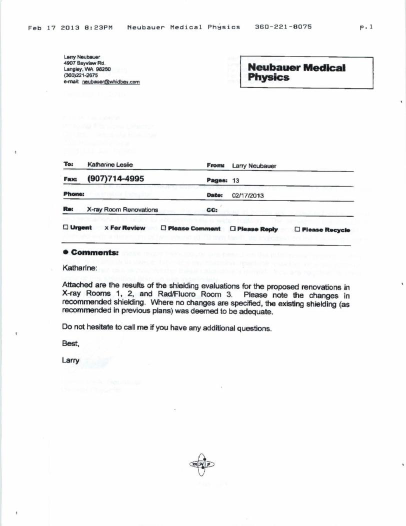

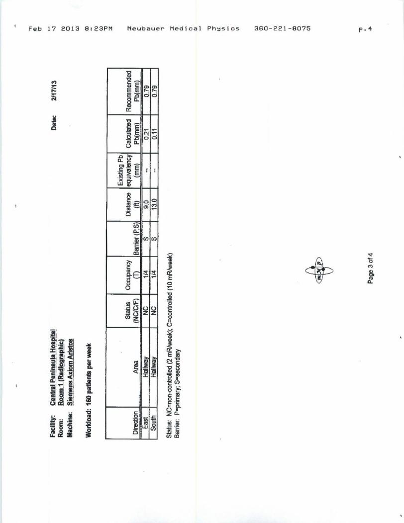
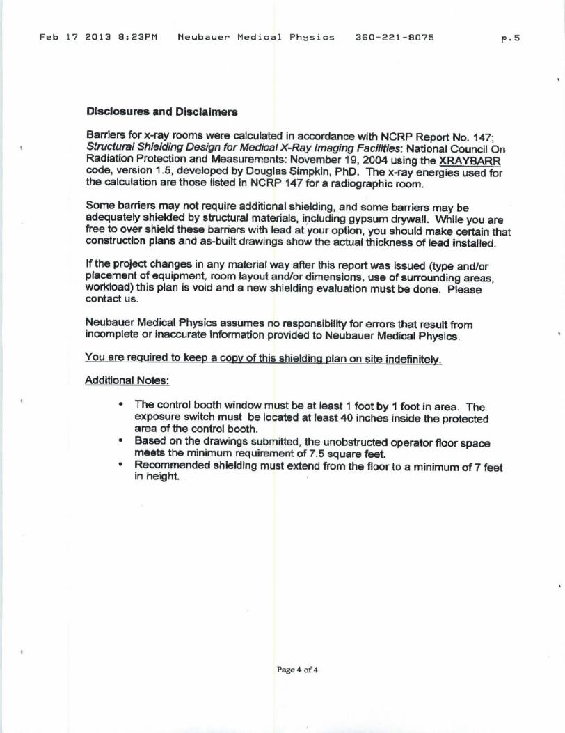
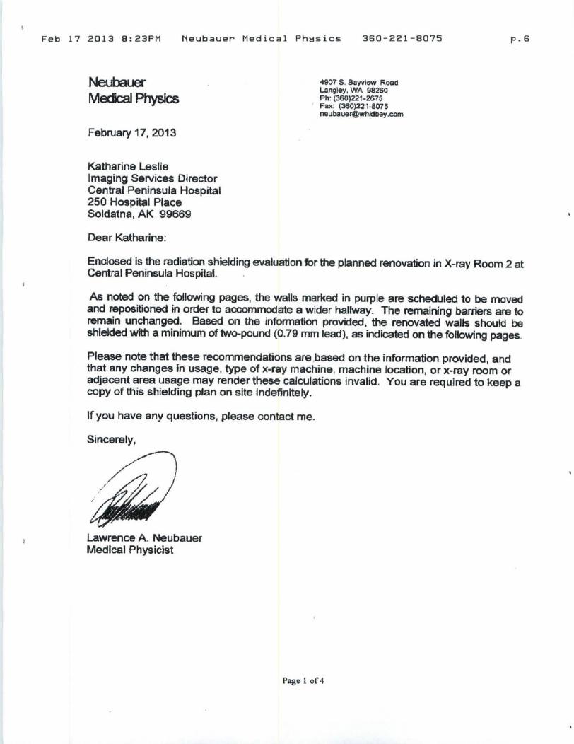
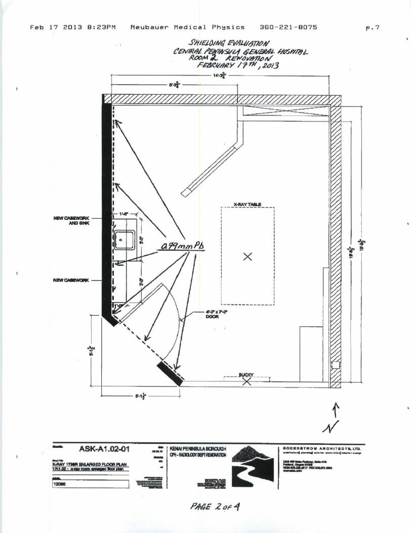
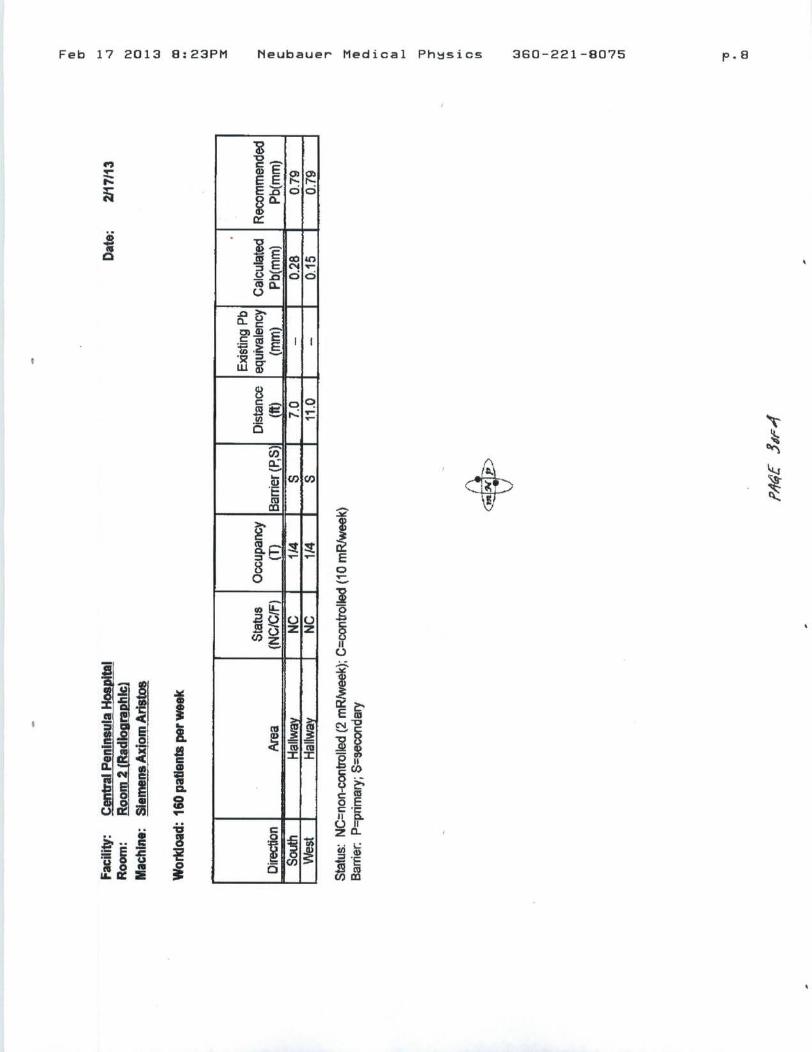
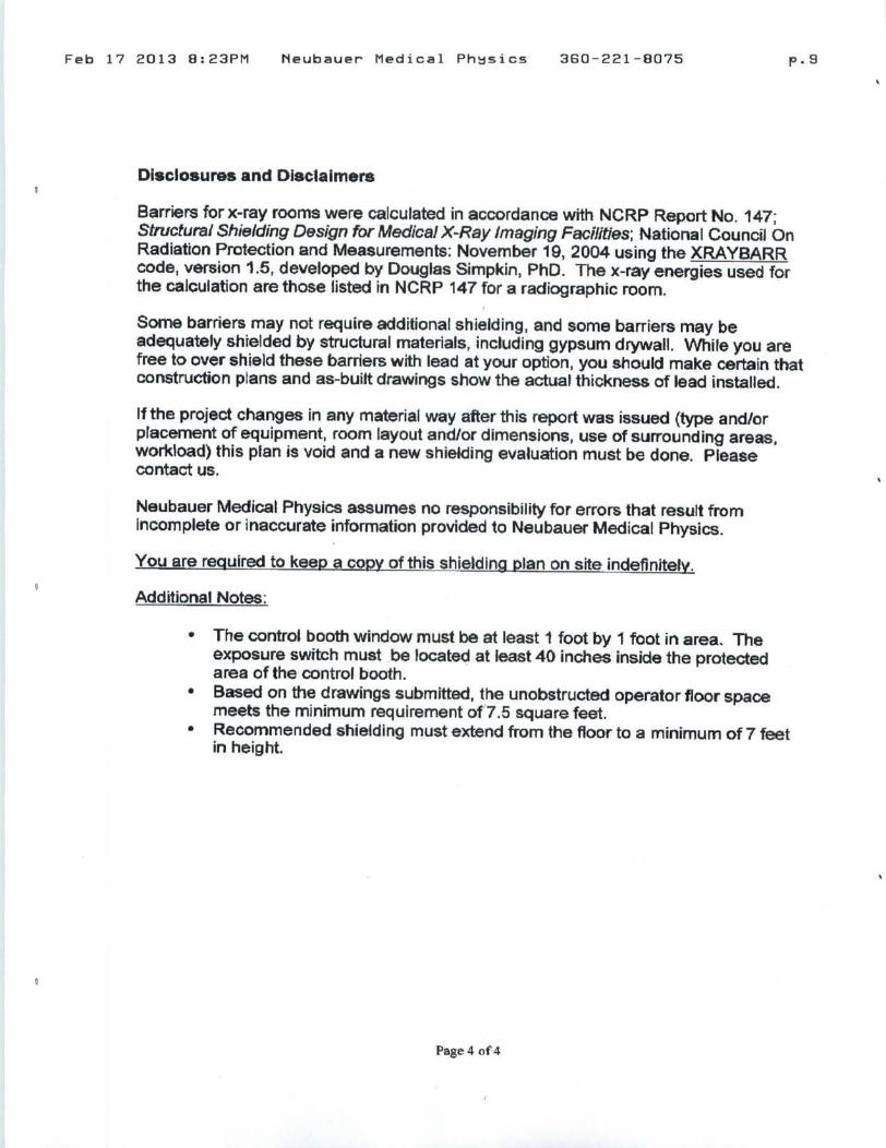
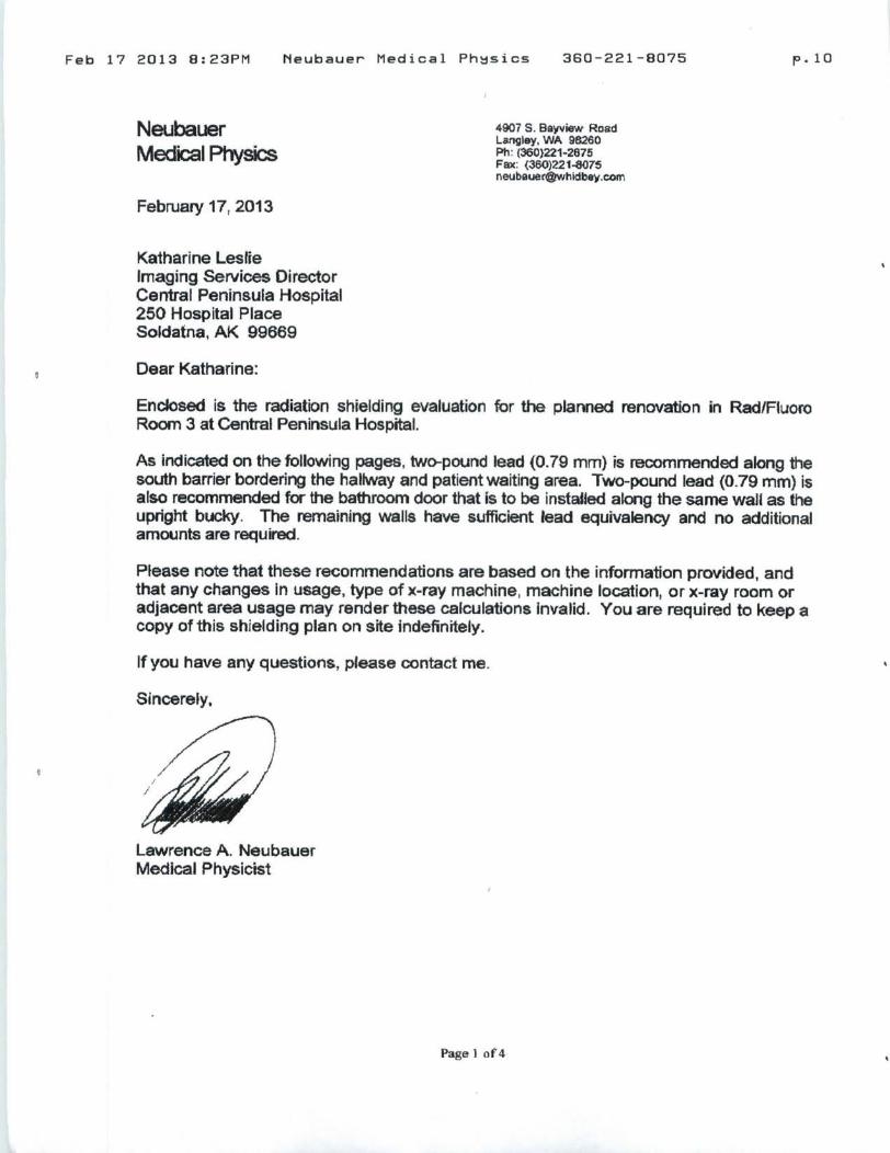
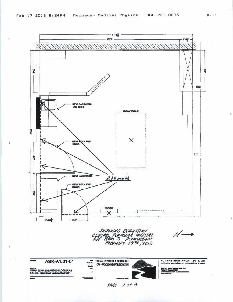
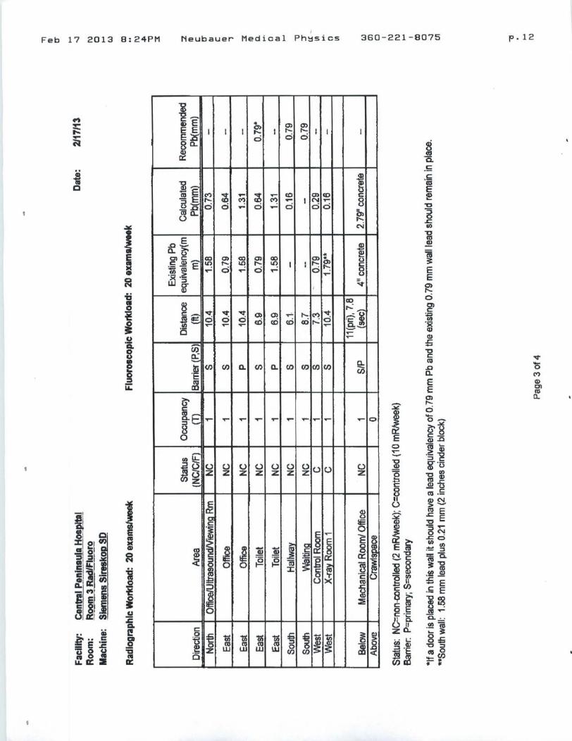
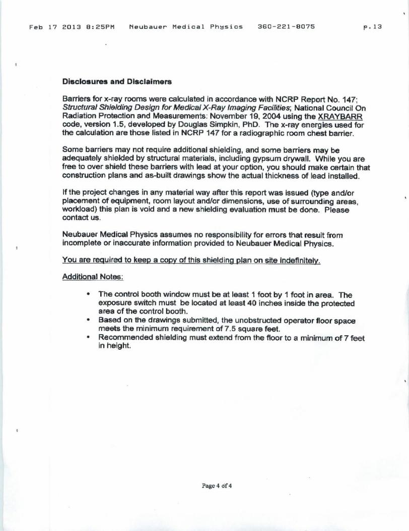
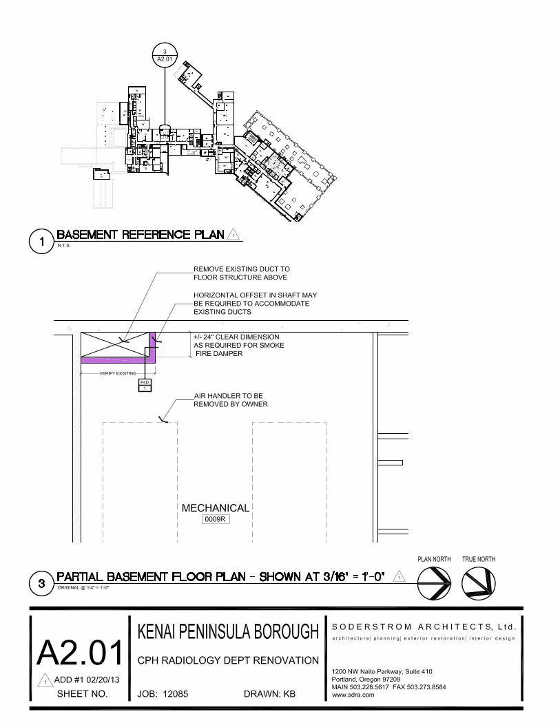

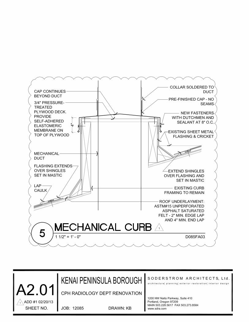
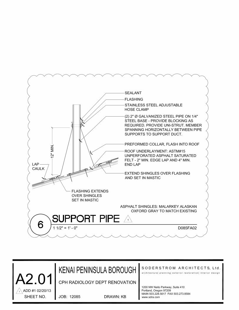
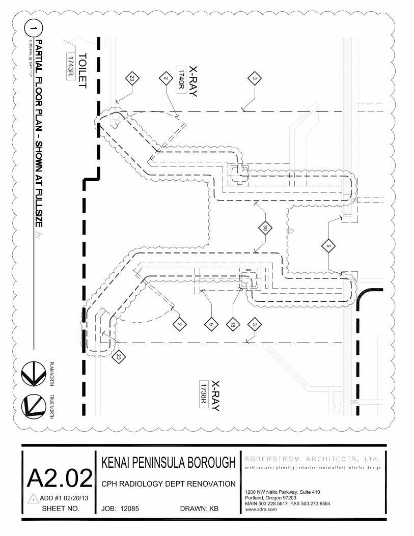

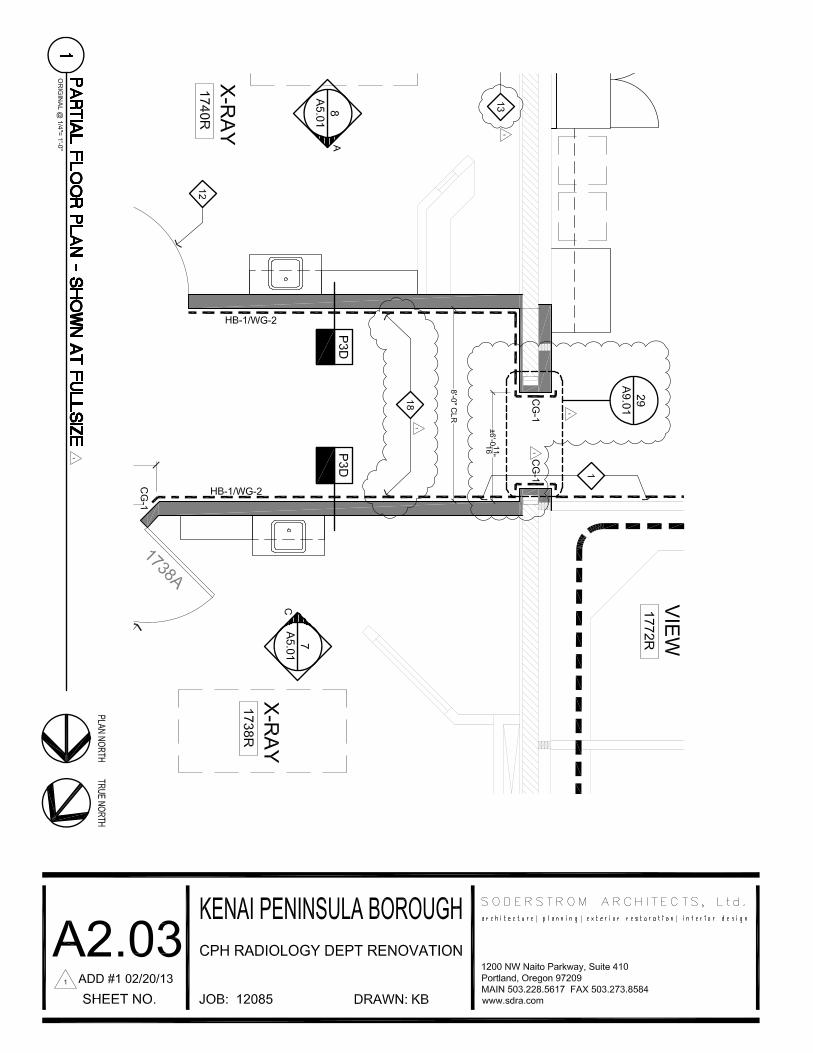
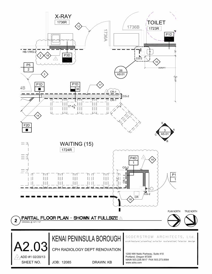
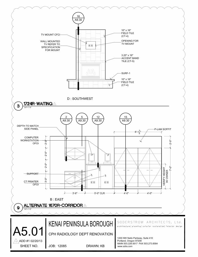
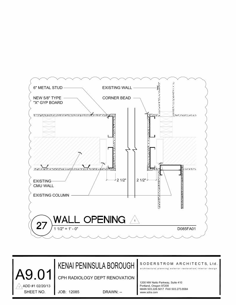
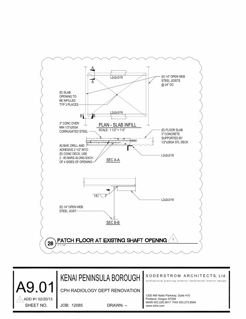
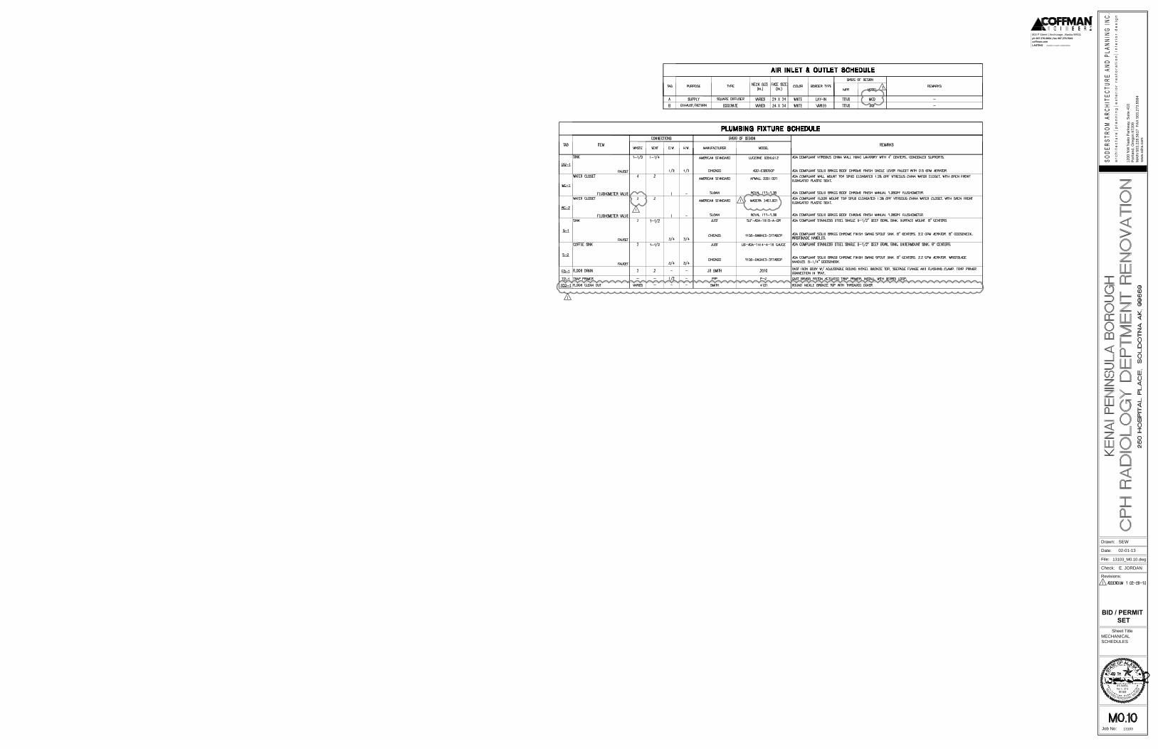
1200 N
W N
aito P
arkw
ay, S
uite 410
Portland, O
regon 97209
MA
IN
503.228.5617 F
AX
503.273.8584
ww
w.sdra.com
Drawn:
File:
Date:
Check:
Revisions:
Sheet Title
Job No: 13103
LASTING creativity | results | relationships
coffman.com
ph 907.276.6664 | fax 907.276.5042
800 F Street | Anchorage, Alaska 99501
Feb 19, 2013
BID / PERMIT
SET
02-01-13
MECHANICAL
SCHEDULES
E. JORDAN
13103_M0.10.dwg
SEW
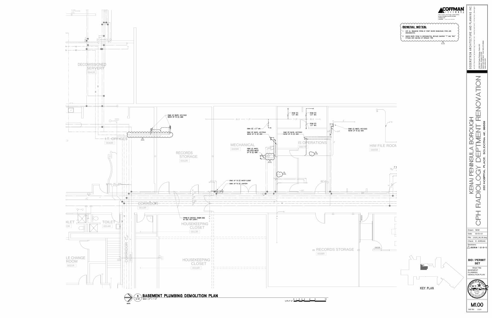
FEFE
I.T. OFFICES
0040R
CLOSET
0016R
ROOM
0021R
TOILET
0014R
STORAGE
0012R
MECHANICAL
0009R
IS OPERATIONS
0007R
HIM FILE ROOM B
0005R
RECORDS STORAGE
0008R
SERVERY
0041R
TOILET
0022R
CORRIDOR
0010R
CO
RR
ID
OR
0015R
CLOSET
0013R
1200 N
W N
aito P
arkw
ay, S
uite 410
Portland, O
regon 97209
MA
IN
503.228.5617 F
AX
503.273.8584
ww
w.sdra.com
Drawn:
File:
Date:
Check:
Revisions:
Sheet Title
Job No: 13103
LASTING creativity | results | relationships
coffman.com
ph 907.276.6664 | fax 907.276.5042
800 F Street | Anchorage, Alaska 99501
Feb 19, 2013
BID / PERMIT
SET
02-01-13
BASEMENT
PLUMBING
DEMOLITION PLAN
E. JORDAN
13103_M1.00.dwg
SEW
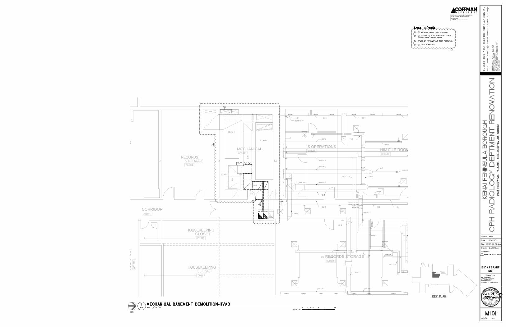
I.T. OFFICES
CLOSET
0016R
STORAGE
0012R
MECHANICAL
0009R
IS OPERATIONS
0007R
HIM FILE ROOM B
0005R
RECORDS STORAGE
0008R
CORRIDOR
0010R
CO
RR
ID
OR
0015R
CLOSET
0013R
1200 N
W N
aito P
arkw
ay, S
uite 410
Portland, O
regon 97209
MA
IN
503.228.5617 F
AX
503.273.8584
ww
w.sdra.com
Drawn:
File:
Date:
Check:
Revisions:
Sheet Title
Job No: 13103
LASTING creativity | results | relationships
coffman.com
ph 907.276.6664 | fax 907.276.5042
800 F Street | Anchorage, Alaska 99501
Feb 19, 2013
BID / PERMIT
SET
02-01-13
MECHANICAL
BASEMENT
DEMOLITION-HVAC
E. JORDAN
13103_M1.01.dwg
SEW
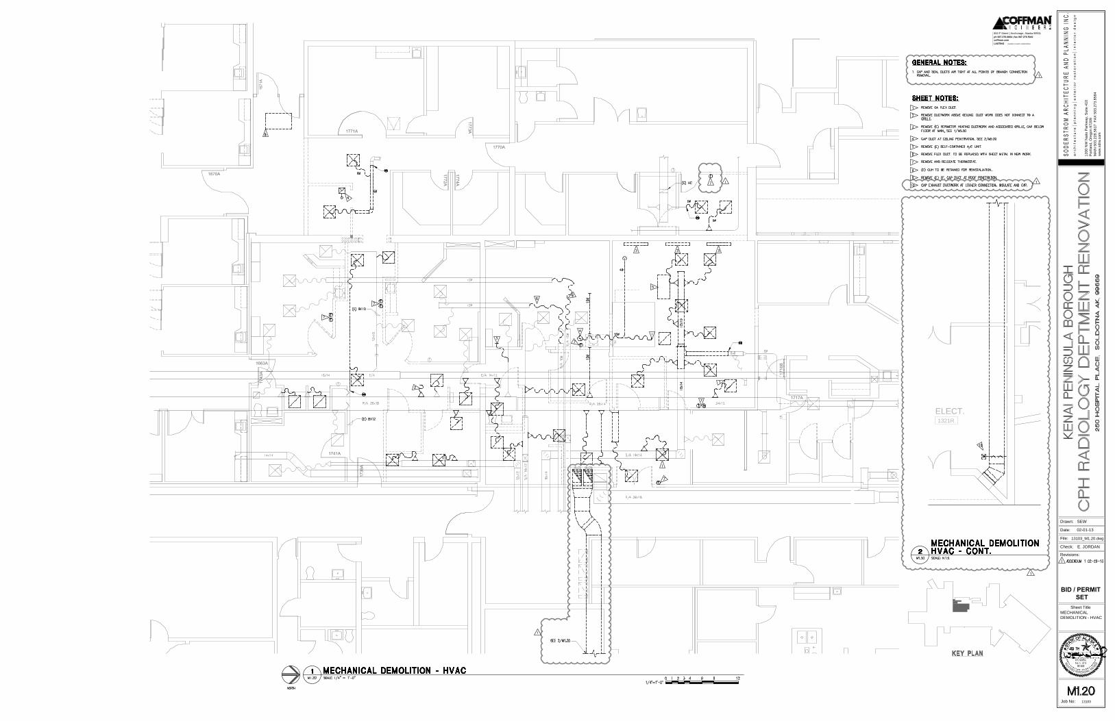
FE
CR
ELECT.
1321R
1200 N
W N
aito P
arkw
ay, S
uite 410
Portland, O
regon 97209
MA
IN
503.228.5617 F
AX
503.273.8584
ww
w.sdra.com
Drawn:
File:
Date:
Check:
Revisions:
Sheet Title
Job No: 13103
LASTING creativity | results | relationships
coffman.com
ph 907.276.6664 | fax 907.276.5042
800 F Street | Anchorage, Alaska 99501
Feb 19, 2013
BID / PERMIT
SET
02-01-13
MECHANICAL
DEMOLITION - HVAC
E. JORDAN
13103_M1.20.dwg
SEW
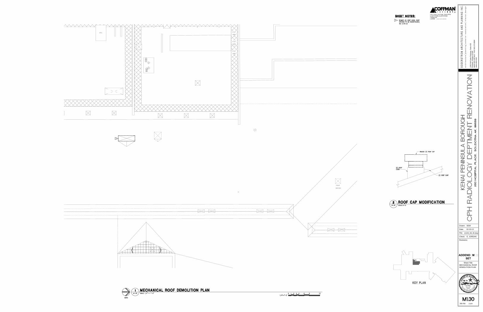
RTU
PIPE
2 1/2"
PIPE
2 1/2"
PIPE
2 1/2"
24x24
DECOM.
OD
RD
1200 N
W N
aito P
arkw
ay, S
uite 410
Portland, O
regon 97209
MA
IN
503.228.5617 F
AX
503.273.8584
ww
w.sdra.com
Drawn:
File:
Date:
Check:
Revisions:
Sheet Title
Job No: 13103
LASTING creativity | results | relationships
coffman.com
ph 907.276.6664 | fax 907.276.5042
800 F Street | Anchorage, Alaska 99501
Feb 19, 2013
02-20-13
ADDENDUM #1
SET
MECHANICAL ROOF
DEMOLITION PLAN
E. JORDAN
12103_M1.30.dwg
SEW
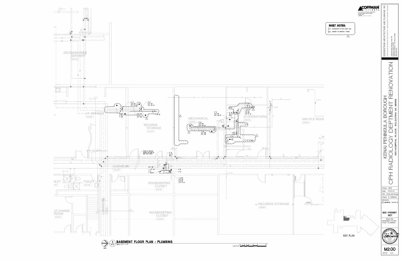
FEFE
I.T. OFFICES
0040R
CLOSET
0016R
ROOM
0021R
TOILET
0014R
STORAGE
0012R
MECHANICAL
0009R
IS OPERATIONS
0007R
HIM FILE ROOM B
0005R
RECORDS STORAGE
0008R
SERVERY
0041R
TOILET
0022R
CORRIDOR
0010R
CO
RR
ID
OR
0015R
CLOSET
0013R
1200 N
W N
aito P
arkw
ay, S
uite 410
Portland, O
regon 97209
MA
IN
503.228.5617 F
AX
503.273.8584
ww
w.sdra.com
Drawn:
File:
Date:
Check:
Revisions:
Sheet Title
Job No: 13103
LASTING creativity | results | relationships
coffman.com
ph 907.276.6664 | fax 907.276.5042
800 F Street | Anchorage, Alaska 99501
Feb 19, 2013
BID / PERMIT
SET
02-01-13
BASEMENT FLOOR
PLAN - PLUMBING
E. JORDAN
13103_M2.00.dwg
SEW
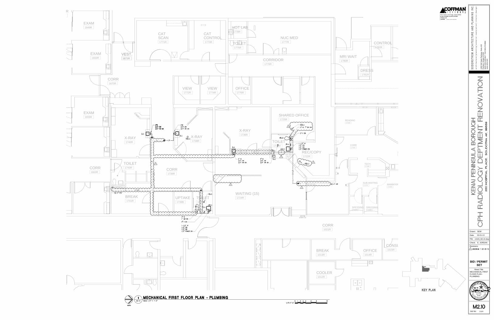
CR
CR
FE
C (R
ELO
CA
TE
)
CR
EP 0074 - 'EK'
REC/COPY
1722R
WAITING (15)
1724R
TOILET
1723R
SHARED OFFICE
1725R
TOILET
1737R
EXAM
1659R
EXAM
1650R
EXAM
1649R
CORR
VEST.
1671R
COOLER
1012R
CONSULT
1015R
OFFICE
1014R
BREAK
1013R
CORR
1670R
VEST.
1671R
CORR
1021R
X-RAY
1738R
X-RAY
1740R
X-RAY
1736R
VIEW
1772R
VIEW
1774R
OFFICE
1776R
CORRIDOR
1770R
SCAN
1771R
CONTROL
1773R
NUC MED
1777R
TOILET
1775R
HOT LAB
1778R
CONTROL
1782R
DRESS
1781R
MRI WAIT
1780R
CAT CAT
MAMMOGRAPHY
1720R
TECH.
1718R
CORR
SUB-WAITING
1717R
DRESSING
1719BR
DRESSING
1719AR
READING
1715R
CORR
1663R
BREAK
1741R
TOILET
1743R
CORR
1733R
CORR
1739R
CR
UPTAKE
1739B
1200 N
W N
aito P
arkw
ay, S
uite 410
Portland, O
regon 97209
MA
IN
503.228.5617 F
AX
503.273.8584
ww
w.sdra.com
Drawn:
File:
Date:
Check:
Revisions:
Sheet Title
Job No: 13103
LASTING creativity | results | relationships
coffman.com
ph 907.276.6664 | fax 907.276.5042
800 F Street | Anchorage, Alaska 99501
Feb 19, 2013
BID / PERMIT
SET
02-01-13
MECHANICAL FIRST
FLOOR PLAN -
PLUMBING
E. JORDAN
13103_M2.10.dwg
SEW
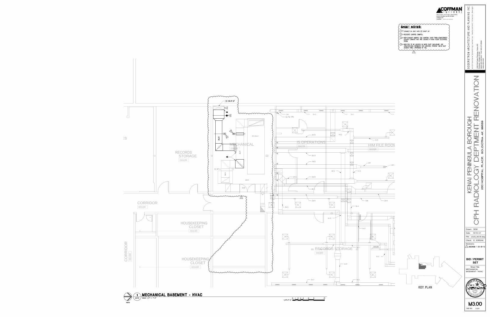
FE
I.T. OFFICES
CLOSET
0016R
STORAGE
0012R
MECHANICAL
0009R
IS OPERATIONS
0007R
HIM FILE ROOM B
0005R
RECORDS STORAGE
0008R
CORRIDOR
0010R
CO
RR
ID
OR
0015R
CLOSET
0013R
1200 N
W N
aito P
arkw
ay, S
uite 410
Portland, O
regon 97209
MA
IN
503.228.5617 F
AX
503.273.8584
ww
w.sdra.com
Drawn:
File:
Date:
Check:
Revisions:
Sheet Title
Job No: 13103
LASTING creativity | results | relationships
coffman.com
ph 907.276.6664 | fax 907.276.5042
800 F Street | Anchorage, Alaska 99501
Feb 19, 2013
BID / PERMIT
SET
02-01-13
MECHANICAL
BASEMENT - HVAC
E. JORDAN
13103_M3.00.dwg
SEW
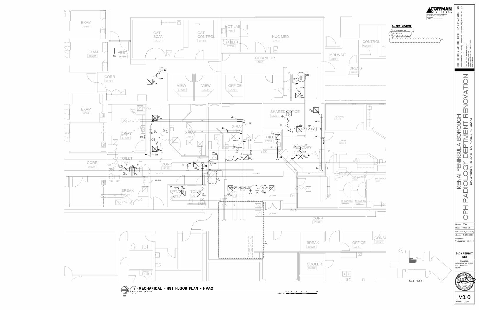
CR
CR
CR
EP 0074 - 'EK'
REC/COPY
1722R
WAITING (15)
1724R
TOILET
1723R
SHARED OFFICE
1725R
TOILET
1737R
EXAM
1659R
EXAM
1650R
EXAM
1649R
CORR
VEST.
1671R
COOLER
1012R
CONSULT
1015R
OFFICE
1014R
BREAK
1013R
CORR
1670R
VEST.
1671R
CORR
1021R
X-RAY
1738R
X-RAY
1740R
X-RAY
1736R
VIEW
1772R
VIEW
1774R
OFFICE
1776R
CORRIDOR
1770R
SCAN
1771R
CONTROL
1773R
NUC MED
1777R
TOILET
1775R
HOT LAB
1778R
CONTROL
1782R
DRESS
1781R
MRI WAIT
1780R
CAT CAT
MAMMOGRAPHY
1720R
TECH.
1718R
CORR
SUB-WAITING
1717R
DRESSING
1719BR
DRESSING
1719AR
READING
1715R
CORR
1663R
BREAK
1741R
TOILET
1743R
CORR
1733R
CORR
1739R
CR
UPTAKE
1739B
1200 N
W N
aito P
arkw
ay, S
uite 410
Portland, O
regon 97209
MA
IN
503.228.5617 F
AX
503.273.8584
ww
w.sdra.com
Drawn:
File:
Date:
Check:
Revisions:
Sheet Title
Job No: 13103
LASTING creativity | results | relationships
coffman.com
ph 907.276.6664 | fax 907.276.5042
800 F Street | Anchorage, Alaska 99501
Feb 19, 2013
BID / PERMIT
SET
02-01-13
MECHANICAL FIRST
FLOOR PLAN -
HVAC
E. JORDAN
13103_M3.10.dwg
SEW
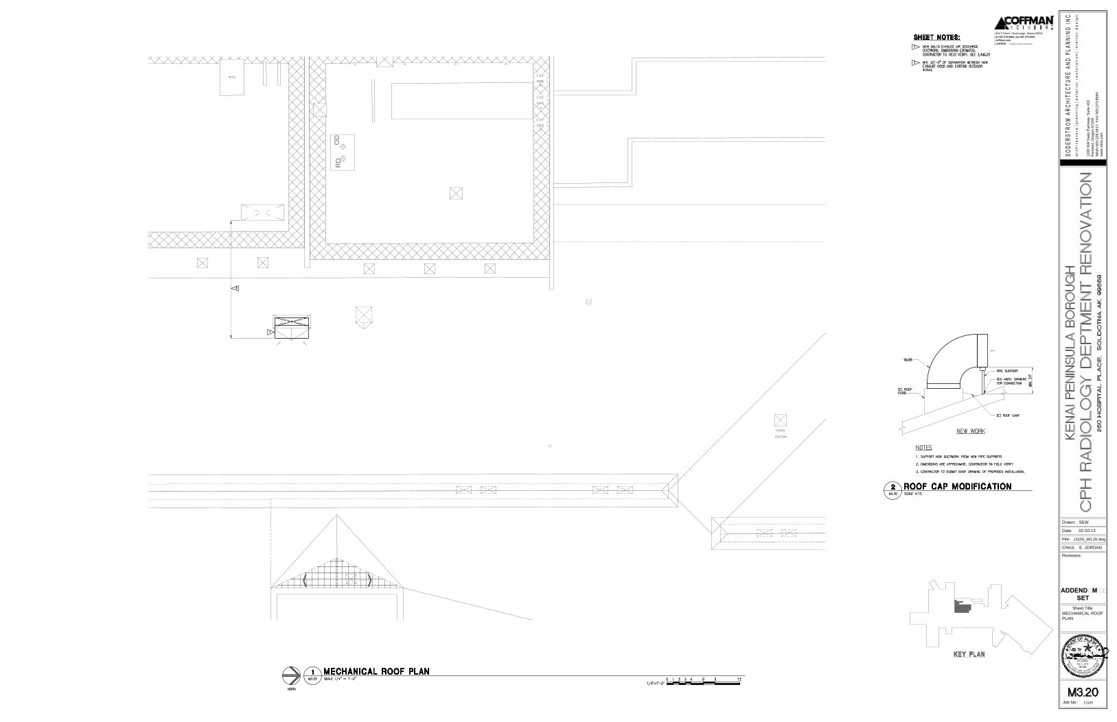
RTU
PIPE
2 1/2"
PIPE
2 1/2"
PIPE
2 1/2"
24x24
DECOM.
OD
RD
1200 N
W N
aito P
arkw
ay, S
uite 410
Portland, O
regon 97209
MA
IN
503.228.5617 F
AX
503.273.8584
ww
w.sdra.com
Drawn:
File:
Date:
Check:
Revisions:
Sheet Title
Job No: 13103
LASTING creativity | results | relationships
coffman.com
ph 907.276.6664 | fax 907.276.5042
800 F Street | Anchorage, Alaska 99501
Feb 19, 2013
02-20-13
ADDENDUM #1
SET
MECHANICAL ROOF
PLAN
E. JORDAN
13103_M3.20.dwg
SEW
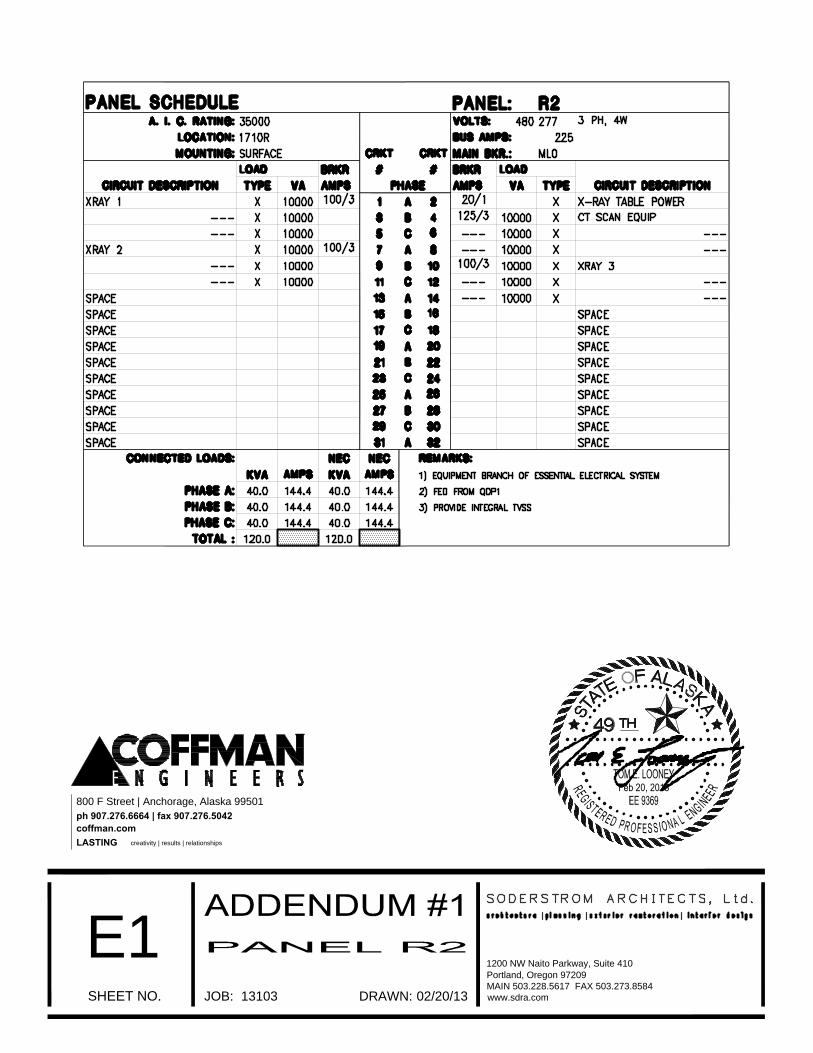
1200 NW Naito Parkway, Suite 410
Portland, Oregon 97209
MAIN 503.228.5617 FAX 503.273.8584
www.sdra.comSHEET NO. JOB: DRAWN:
E1
13103 02/20/13
LASTINGcreativity | results | relationships
coffman.com
ph 907.276.6664 | fax 907.276.5042
800 F Street | Anchorage, Alaska 99501
Feb 20, 2013
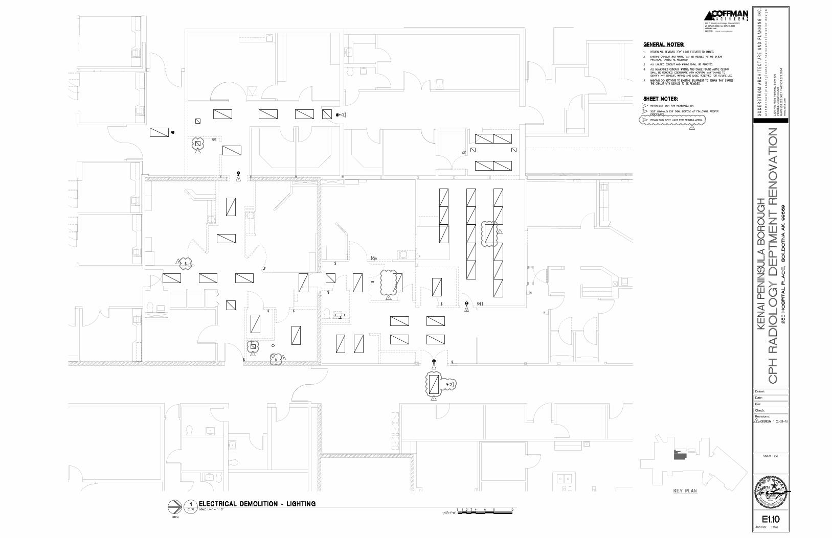
FE
CR
CR
CR
CR
1200 N
W N
aito P
arkw
ay, S
uite 410
Portland, O
regon 97209
MA
IN
503.228.5617 F
AX
503.273.8584
ww
w.sdra.com
Drawn:
File:
Date:
Check:
Revisions:
Sheet Title
Job No: 13103
LASTING creativity | results | relationships
coffman.com
ph 907.276.6664 | fax 907.276.5042
800 F Street | Anchorage, Alaska 99501
Feb 20, 2013
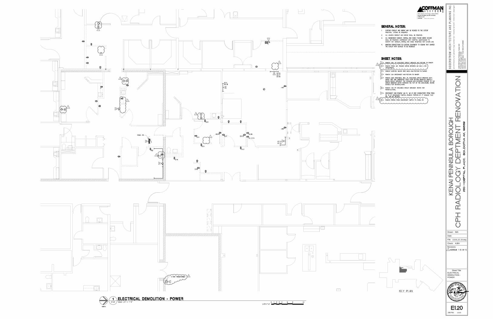
FE
OV
CR
CR
CR
CR
1200 N
W N
aito P
arkw
ay, S
uite 410
Portland, O
regon 97209
MA
IN
503.228.5617 F
AX
503.273.8584
ww
w.sdra.com
Drawn:
File:
Date:
Check:
Revisions:
Sheet Title
Job No: 13103
LASTING creativity | results | relationships
coffman.com
ph 907.276.6664 | fax 907.276.5042
800 F Street | Anchorage, Alaska 99501
Feb 20, 2013
ELECTRICAL
DEMOLITION -
POWER
AJBV
13103_E1.20.dwg
IMA
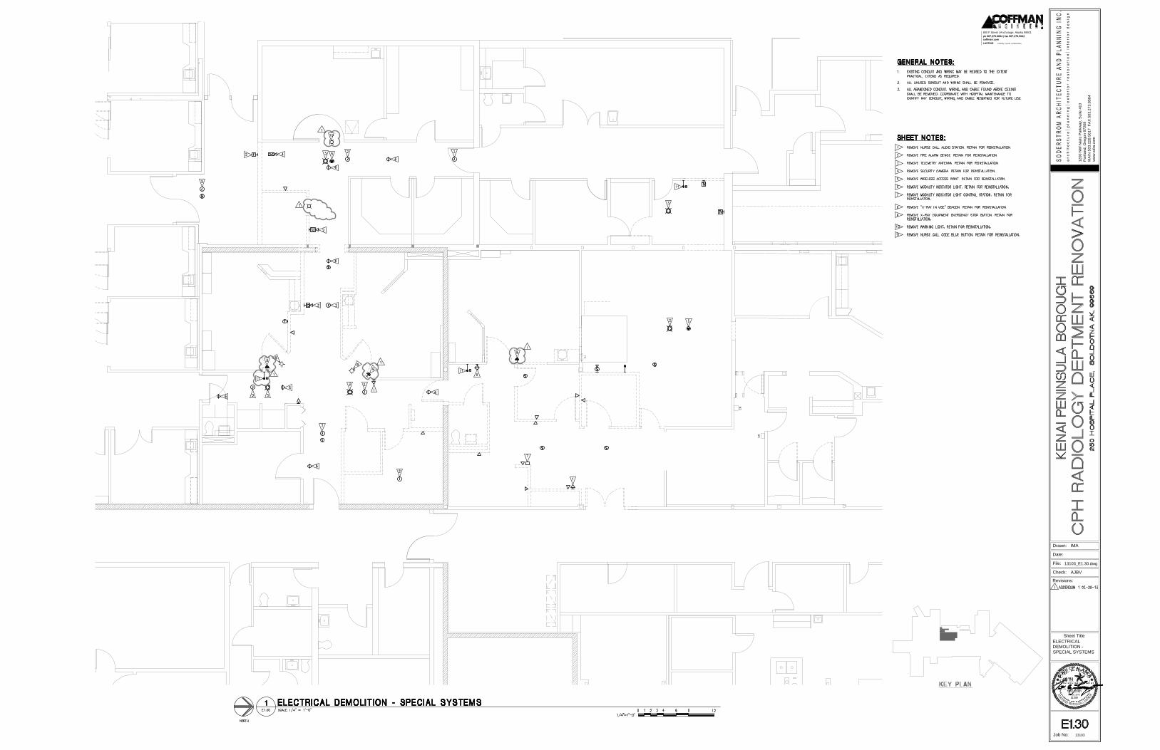
FE
CR
CR
CR
CR
1200 N
W N
aito P
arkw
ay, S
uite 410
Portland, O
regon 97209
MA
IN
503.228.5617 F
AX
503.273.8584
ww
w.sdra.com
Drawn:
File:
Date:
Check:
Revisions:
Sheet Title
Job No: 13103
LASTING creativity | results | relationships
coffman.com
ph 907.276.6664 | fax 907.276.5042
800 F Street | Anchorage, Alaska 99501
Feb 20, 2013
ELECTRICAL
DEMOLITION -
SPECIAL SYSTEMS
AJBV
13103_E1.30.dwg
IMA
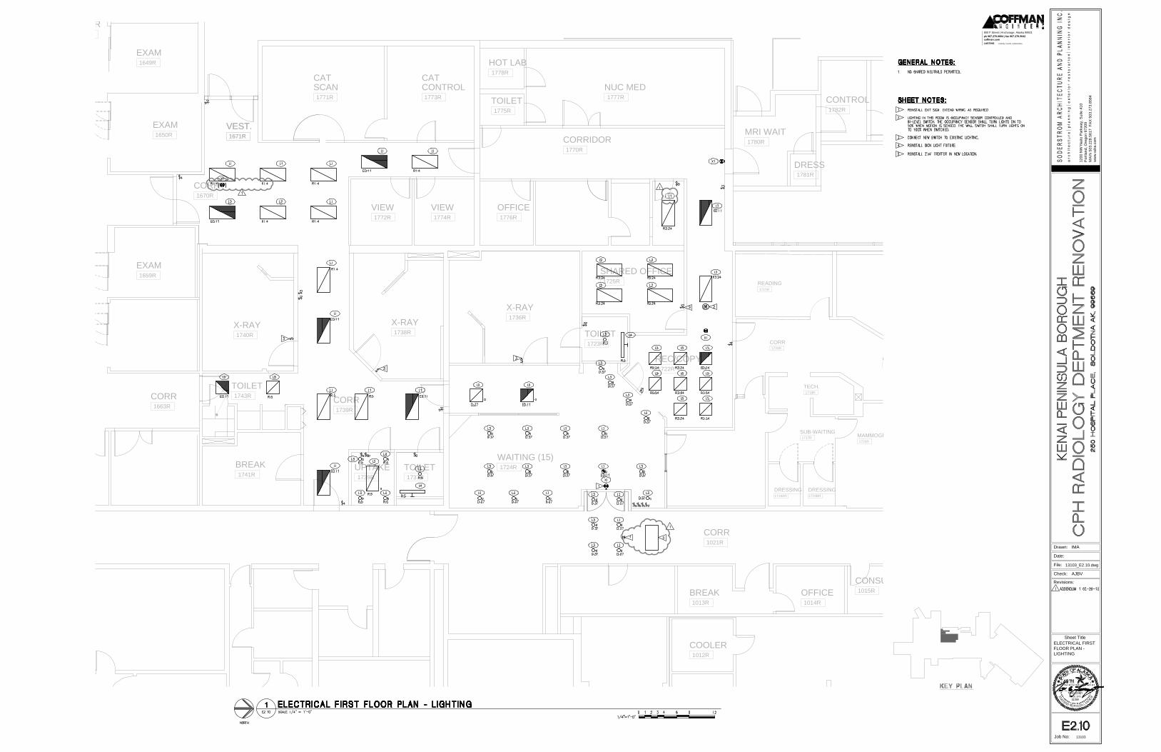
REC/COPY
1722R
WAITING (15)
1724R
TOILET
1723R
SHARED OFFICE
1725R
TOILET
1737R
EXAM
1659R
EXAM
1650R
EXAM
1649R
CORR
VEST.
1671R
COOLER
1012R
CONSULT
1015R
OFFICE
1014R
BREAK
1013R
CORR
1670R
VEST.
1671R
CORR
1021R
X-RAY
1738R
X-RAY
1740R
X-RAY
1736R
VIEW
1772R
VIEW
1774R
OFFICE
1776R
CORRIDOR
1770R
SCAN
1771R
CONTROL
1773R
NUC MED
1777R
TOILET
1775R
HOT LAB
1778R
CONTROL
1782R
DRESS
1781R
MRI WAIT
1780R
CAT CAT
MAMMOGRAPHY
1720R
BIOPSY
TECH.
1718R
CORR
SUB-WAITING
1717R
DRESSING
1719BR
DRESSING
1719AR
READING
1715R
CORR
1663R
BREAK
1741R
TOILET
1743R
CORR
1733R
CORR
1739R
UPTAKE
1739B
1200 N
W N
aito P
arkw
ay, S
uite 410
Portland, O
regon 97209
MA
IN
503.228.5617 F
AX
503.273.8584
ww
w.sdra.com
Drawn:
File:
Date:
Check:
Revisions:
Sheet Title
Job No: 13103
LASTING creativity | results | relationships
coffman.com
ph 907.276.6664 | fax 907.276.5042
800 F Street | Anchorage, Alaska 99501
Feb 20, 2013
ELECTRICAL FIRST
FLOOR PLAN -
LIGHTING
AJBV
13103_E2.10.dwg
IMA
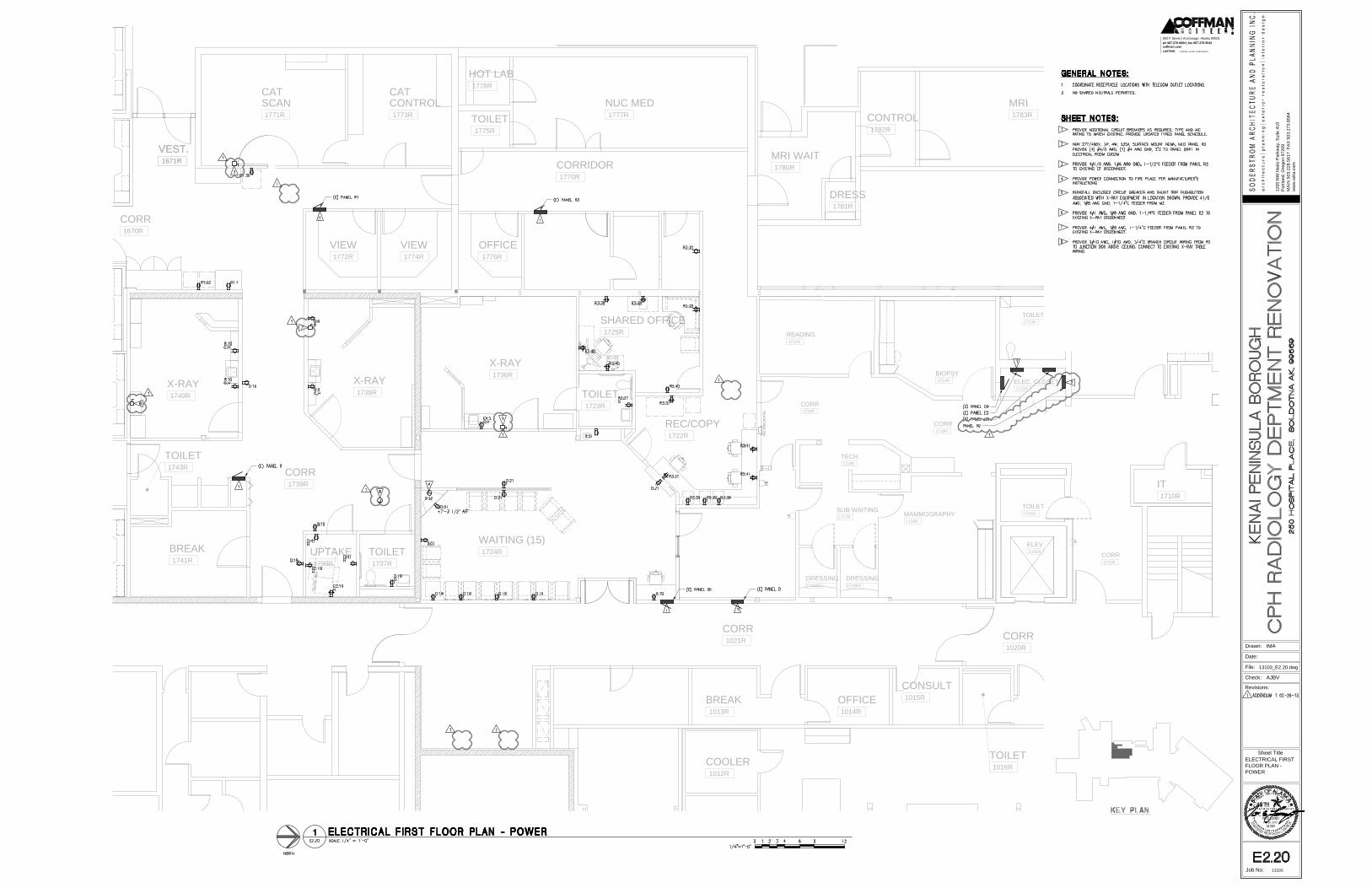
CR
CR
PP
FE
C (R
EL
OC
AT
E)
CR
REC/COPY
1722R
WAITING (15)
1724R
TOILET
1723R
SHARED OFFICE
1725R
TOILET
1737R
VEST.
1671R
COOLER
1012R
CART WASH
1017R
TOILET
1016R
CONSULT
1015R
OFFICE
1014R
BREAK
1013R
CORR
1670R
VEST.
1671R
CORR
1021R
CORR
1020R
IT
1710R
X-RAY
1738R
X-RAY
1740R
X-RAY
1736R
VIEW
1772R
VIEW
1774R
OFFICE
1776R
CORRIDOR
1770R
SCAN
1771R
CONTROL
1773R
NUC MED
1777R
TOILET
1775R
HOT LAB
1778R
MRI
1783R
CONTROL
1782R
DRESS
1781R
MRI WAIT
1780R
CAT CAT
CORR
1732R
ELEV
E101R
MAMMOGRAPHY
1720R
BIOPSY
1714R
ULTRASOUND
1712R
TECH.
1718R
CORR
1733R
SUB-WAITING
1717R
DRESSING
1719BR
DRESSING
1719AR
READING
1715R
TOILET
1713R
ELEC. CLOSET
1711R
TOILET
1721R
BREAK
1741R
TOILET
1743R
CORR
1733R
CORR
1739R
UPTAKE
1739B
1200 N
W N
aito P
arkw
ay, S
uite 410
Portland, O
regon 97209
MA
IN
503.228.5617 F
AX
503.273.8584
ww
w.sdra.com
Drawn:
File:
Date:
Check:
Revisions:
Sheet Title
Job No: 13103
LASTING creativity | results | relationships
coffman.com
ph 907.276.6664 | fax 907.276.5042
800 F Street | Anchorage, Alaska 99501
Feb 20, 2013
ELECTRICAL FIRST
FLOOR PLAN -
POWER
AJBV
13103_E2.20.dwg
IMA
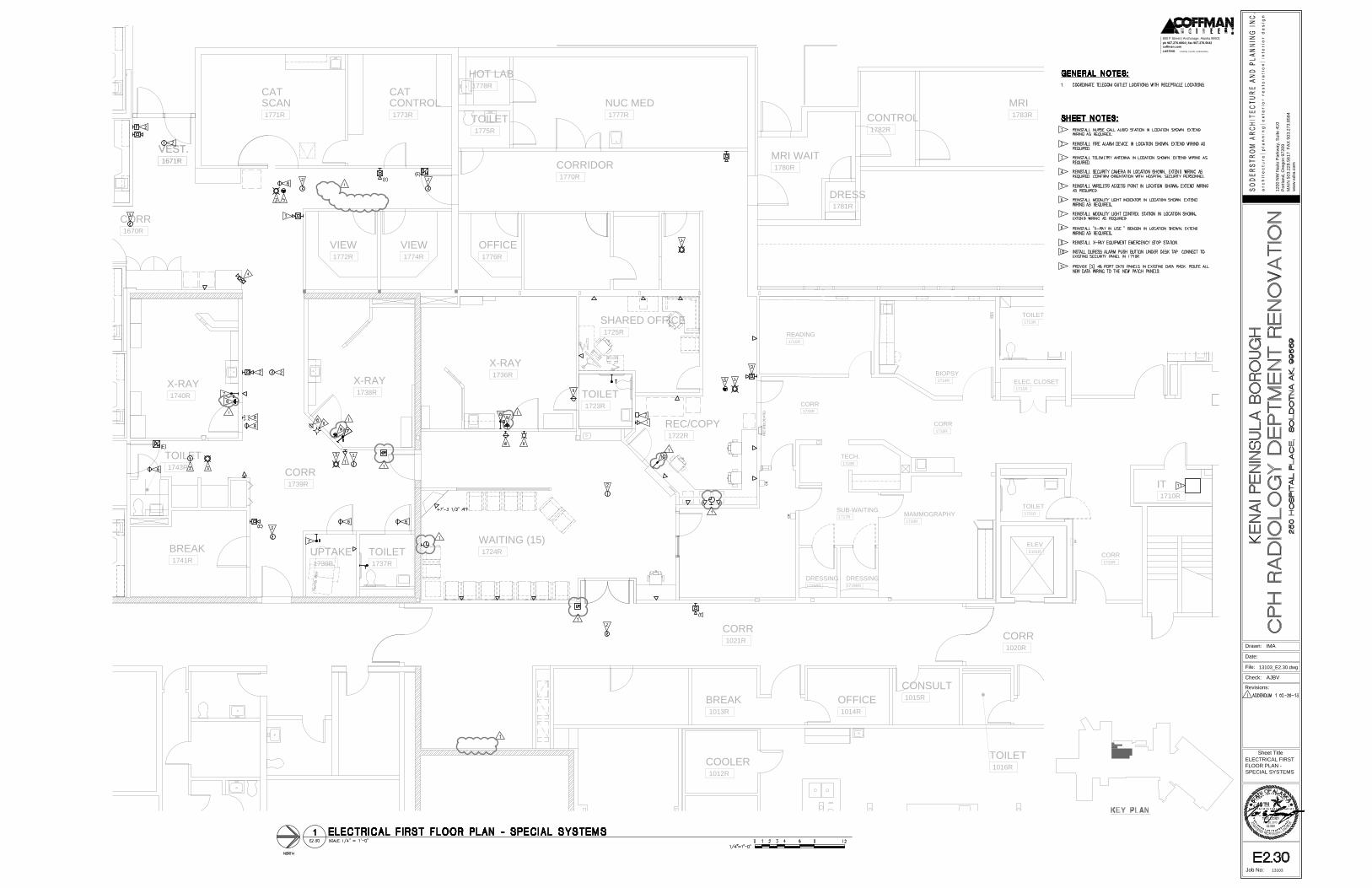
OV
CR
CR
PP
FE
C (R
EL
OC
AT
E)
CR
REC/COPY
1722R
WAITING (15)
1724R
TOILET
1723R
SHARED OFFICE
1725R
TOILET
1737R
VEST.
1671R
COOLER
1012R
CART WASH
1017R
TOILET
1016R
CONSULT
1015R
OFFICE
1014R
BREAK
1013R
CORR
1670R
VEST.
1671R
CORR
1021R
CORR
1020R
IT
1710R
X-RAY
1738R
X-RAY
1740R
X-RAY
1736R
VIEW
1772R
VIEW
1774R
OFFICE
1776R
CORRIDOR
1770R
SCAN
1771R
CONTROL
1773R
NUC MED
1777R
TOILET
1775R
HOT LAB
1778R
MRI
1783R
CONTROL
1782R
DRESS
1781R
MRI WAIT
1780R
CAT CAT
CORR
1732R
ELEV
E101R
MAMMOGRAPHY
1720R
BIOPSY
1714R
ULTRASOUND
1712R
TECH.
1718R
CORR
1733R
SUB-WAITING
1717R
DRESSING
1719BR
DRESSING
1719AR
READING
1715R
TOILET
1713R
ELEC. CLOSET
1711R
TOILET
1721R
BREAK
1741R
TOILET
1743R
CORR
1733R
CORR
1739R
CR
UPTAKE
1739B
1200 N
W N
aito P
arkw
ay, S
uite 410
Portland, O
regon 97209
MA
IN
503.228.5617 F
AX
503.273.8584
ww
w.sdra.com
Drawn:
File:
Date:
Check:
Revisions:
Sheet Title
Job No: 13103
LASTING creativity | results | relationships
coffman.com
ph 907.276.6664 | fax 907.276.5042
800 F Street | Anchorage, Alaska 99501
Feb 20, 2013
ELECTRICAL FIRST
FLOOR PLAN -
SPECIAL SYSTEMS
AJBV
13103_E2.30.dwg
IMA
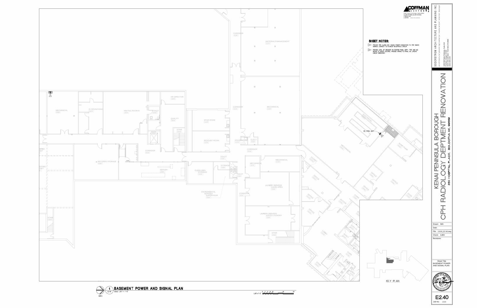
FP
FE
FE
FE
FE
CLOSET
0016R
STORAGE
MECHANICAL
0009R
IS OPERATIONS
0007R
HIM FILE ROOM B
0005R
QUALITY
0003R
HR DIRECTOR
0004R
SPUR ROOM
0113R
REDOUBT ROOM
0112R
STORAGE
0101R
SUPERVISOR
0105R
RECORDS STORAGE
0008RMECHANICAL
0107R
MECHANICAL
0110R
CLEAN AREA
0108R
SOILED LAUNDRY
0109R
SERVER
0002R
MECHANICAL
0115R
MATERIALS MANAGEMENT
0117R
L
O
B
B
Y
0
1
0
1
M
E
L
E
V
L
O
B
B
Y
0
1
0
9
M
C
O
R
R
0
1
1
6
M
A
L
Y
E
S
K
A
R
O
O
M
0
1
1
3
M
M
E
N0
1
1
4
M
W
O
M
E
N
0
1
1
5
M
A
L
C
O
V
E
0
1
0
4
M
O
F
F
I
C
E
0
2
0
3
M
O
F
F
I
C
E
0
2
0
2
M
O
F
F
I
C
E
0
2
0
1
M
E
L
E
V
E
Q
U
I
P
0
1
0
6
M
E
L
E
C
0
1
0
7
M
C
O
M
M
0
1
0
8
M
M
E
C
H
A
N
I
C
A
L
0
3
0
1
M
E
L
E
C
T
R
I
C
A
L
0
3
0
2
M
O
F
F
I
C
E
0
3
0
3
M
C
O
R
R
0
1
0
5
M
D
E
N
A
L
I
R
O
O
M
O
F
F
I
C
E
0
4
0
1
M
B
L
O
O
D
G
A
S
0
4
0
2
A
M
S
O
I
L
E
D
0
4
0
7
M
U
R
I
N
E
A
N
A
L
Y
S
I
S
0
4
0
2
B
M
C
L
O
S
E
T
0
2
0
3
A
M
E
L
E
V
#
2
E
0
0
2
M
E
L
E
V
#
1
E
0
0
1
M
U
P
S
T
A
I
R
S
0
0
1
M
T
O
I
L
E
T
0
4
0
9
M
E
L
E
V
#
3
E
0
0
3
M
F
E
C
-
1
F
E
C
-
1
F
E
C
-
1
F
E
C
-
4
F
E
C
-
3
F
E
C
-
3
S
H
A
F
T
E
0
0
4
M
S
U
M
P
P
U
M
P
0
3
0
6
M
O
F
F
I
C
E
0
3
0
5
M
O
F
F
I
C
E
0
3
0
4
M
O
F
F
I
C
E
0
3
0
7
M
S
T
O
R
0
4
1
0
M
CORRIDOR
0001R
TOILET
0006R
CORRIDOR
0100R
CORRIDOR
0102R
TOILET
0103R
TOILET
0104R
STORAGE
0106R
ELECT.
0116R
HOUSEKPING
0114R
CORRIDOR
0118R
STAIR
S005R
STAIR
S003R
STAIR
S006R
ELEV
E001R
CLOSET
0013R
CORRIDOR
0111R
FE
1200 N
W N
aito P
arkw
ay, S
uite 410
Portland, O
regon 97209
MA
IN
503.228.5617 F
AX
503.273.8584
ww
w.sdra.com
Drawn:
File:
Date:
Check:
Revisions:
Sheet Title
Job No: 13103
LASTING creativity | results | relationships
coffman.com
ph 907.276.6664 | fax 907.276.5042
800 F Street | Anchorage, Alaska 99501
Feb 20, 2013
BASEMENT POWER
AND SIGNAL PLAN
AJBV
13103_E2.40.dwg
IMA