Embed Size (px)
Citation preview
Hidetoshi Ochi
Registration number 100029968
2015
Kendo Kata tutorial - Develop the 3DAnimation Synthesiser
Supervised by Dr Rudy Lapeer
University of East Anglia
Faculty of Science
School of Computing Sciences
Abstract
In modern 3D computer graphics applications, skeletal character animation techniques
have been demanded to improve its reality particularity in the field of game and film
industries. However, those applications can be seen in more various field for instance
in educational and medical scenes. Although the techniques are spreading to more and
more area, the requirement for those applications have not changed: character animation
should be realistic and produce natural appearance in both graphical and dynamical. To
represent such a realistic animation, motion capture can be the way to obtain continuous
animations. However, employing those techniques could be challenge to understand and
apply to the applications. Therefore, this project main aim is producing a application
which join several form of animations to produce a set of sequence by employing some
theories for transition, also allows users to be interactive to the software. Particularly
the project focus on the martial art tutorial.
Acknowledgements
I would like to express my special thanks of gratitude to my supervisor Dr Rudy Lapeer
who gave me such a great opportunity to do this project as well as Zelimkhan Gerikhanov
who helped me in doing a lot of research and gave me so many new theories, I am really
thankful to them. The project experience was the most attractive in my whole academic
life.
CMPC3P2Y
Contents
1 Introduction 7
1.1 Aims and Objective . . . . . . . . . . . . . . . . . . . . . . . . . . . . 8
1.2 Structure . . . . . . . . . . . . . . . . . . . . . . . . . . . . . . . . . . 8
2 Background 9
2.1 Model-View-Controller . . . . . . . . . . . . . . . . . . . . . . . . . . 9
2.2 Kendo . . . . . . . . . . . . . . . . . . . . . . . . . . . . . . . . . . . 9
2.3 Theory reviews . . . . . . . . . . . . . . . . . . . . . . . . . . . . . . 10
2.3.1 Character animation . . . . . . . . . . . . . . . . . . . . . . . 10
2.3.2 Quaternions . . . . . . . . . . . . . . . . . . . . . . . . . . . . 11
2.3.3 Interpolation . . . . . . . . . . . . . . . . . . . . . . . . . . . 12
2.3.4 Skeletal animation . . . . . . . . . . . . . . . . . . . . . . . . 14
2.3.5 MD5 . . . . . . . . . . . . . . . . . . . . . . . . . . . . . . . 15
2.4 Related works . . . . . . . . . . . . . . . . . . . . . . . . . . . . . . . 16
2.4.1 Parametrising Blends . . . . . . . . . . . . . . . . . . . . . . . 16
2.4.2 Motion Graph . . . . . . . . . . . . . . . . . . . . . . . . . . . 16
2.4.3 Footprint-driven animation authoring . . . . . . . . . . . . . . 17
3 Implementation 19
3.1 Motion production . . . . . . . . . . . . . . . . . . . . . . . . . . . . 19
3.1.1 EVaRT . . . . . . . . . . . . . . . . . . . . . . . . . . . . . . 19
3.1.2 Modelling . . . . . . . . . . . . . . . . . . . . . . . . . . . . . 23
3.1.3 MotionBuilder . . . . . . . . . . . . . . . . . . . . . . . . . . 26
3.1.4 Export MD5 . . . . . . . . . . . . . . . . . . . . . . . . . . . 30
3.2 Programming . . . . . . . . . . . . . . . . . . . . . . . . . . . . . . . 32
3.2.1 Frameworks . . . . . . . . . . . . . . . . . . . . . . . . . . . . 32
3.2.2 GUI . . . . . . . . . . . . . . . . . . . . . . . . . . . . . . . . 33
3.2.3 Engine . . . . . . . . . . . . . . . . . . . . . . . . . . . . . . 37
4 Outcome and evaluation 38
4.1 Limitation and Improvement . . . . . . . . . . . . . . . . . . . . . . . 39
Reg: 100029968 iii

CMPC3P2Y
5 Conclusion 42
References 43
Reg: 100029968 iv
CMPC3P2Y
List of Figures
1 SLEARP and LERP in 2D representaion . . . . . . . . . . . . . . . . . 13
2 Square Calibration . . . . . . . . . . . . . . . . . . . . . . . . . . . . 20
3 Wand Calibration . . . . . . . . . . . . . . . . . . . . . . . . . . . . . 20
4 Model Edit . . . . . . . . . . . . . . . . . . . . . . . . . . . . . . . . 23
5 Skeleton . . . . . . . . . . . . . . . . . . . . . . . . . . . . . . . . . 24
6 Paint weights . . . . . . . . . . . . . . . . . . . . . . . . . . . . . . . 25
7 Aligned actor and T pose motion . . . . . . . . . . . . . . . . . . . . . 27
8 Characterise . . . . . . . . . . . . . . . . . . . . . . . . . . . . . . . . 27
9 Mismatching . . . . . . . . . . . . . . . . . . . . . . . . . . . . . . . 28
10 Modify animation by control Rig . . . . . . . . . . . . . . . . . . . . . 29
11 Eliminating forward and backward movement . . . . . . . . . . . . . . 30
12 Vertices confusion . . . . . . . . . . . . . . . . . . . . . . . . . . . . . 31
13 Youtube user interface . . . . . . . . . . . . . . . . . . . . . . . . . . 34
14 User Interface Design . . . . . . . . . . . . . . . . . . . . . . . . . . . 35
15 Time-line structer . . . . . . . . . . . . . . . . . . . . . . . . . . . . . 38
16 Sliding problem . . . . . . . . . . . . . . . . . . . . . . . . . . . . . . 41
17 UML class diagram . . . . . . . . . . . . . . . . . . . . . . . . . . . . 45
Reg: 100029968 v

CMPC3P2Y
List of Tables
1 User Manual . . . . . . . . . . . . . . . . . . . . . . . . . . . . . . . . 35
2 Assigned keys . . . . . . . . . . . . . . . . . . . . . . . . . . . . . . . 36
Reg: 100029968 vi
CMPC3P2Y
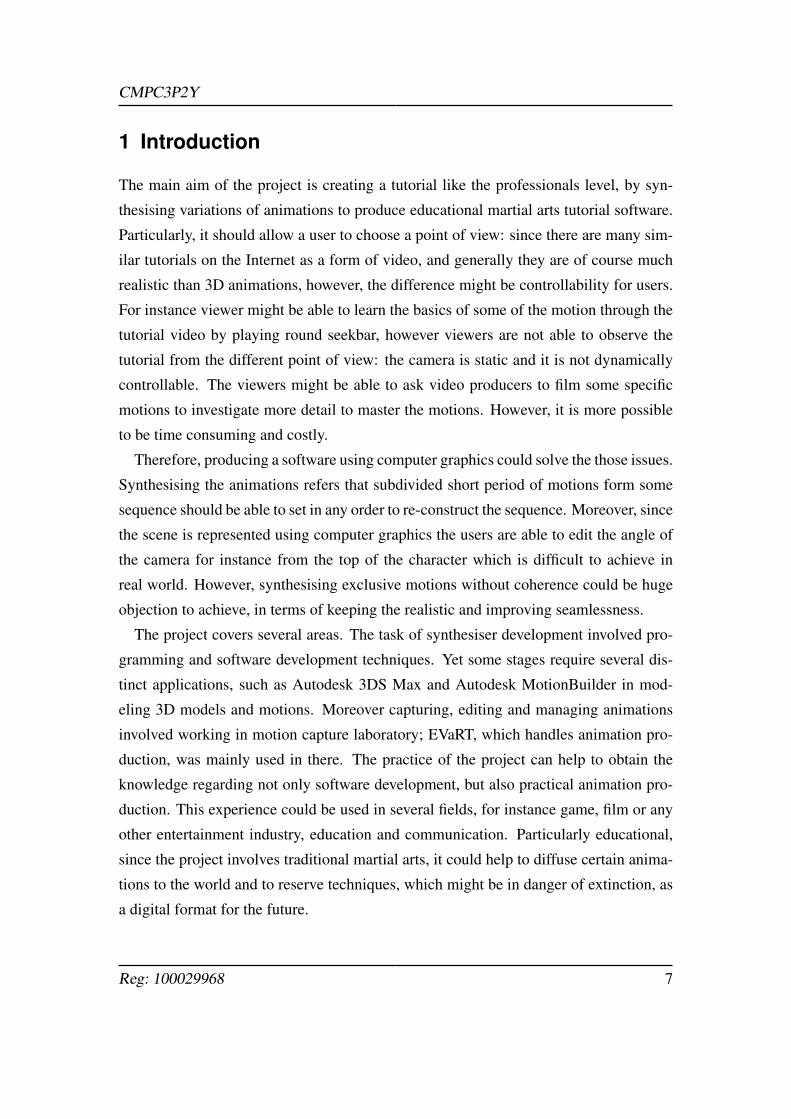
1 Introduction
The main aim of the project is creating a tutorial like the professionals level, by syn-
thesising variations of animations to produce educational martial arts tutorial software.
Particularly, it should allow a user to choose a point of view: since there are many sim-
ilar tutorials on the Internet as a form of video, and generally they are of course much
realistic than 3D animations, however, the difference might be controllability for users.
For instance viewer might be able to learn the basics of some of the motion through the
tutorial video by playing round seekbar, however viewers are not able to observe the
tutorial from the different point of view: the camera is static and it is not dynamically
controllable. The viewers might be able to ask video producers to film some specific
motions to investigate more detail to master the motions. However, it is more possible
to be time consuming and costly.
Therefore, producing a software using computer graphics could solve the those issues.
Synthesising the animations refers that subdivided short period of motions form some
sequence should be able to set in any order to re-construct the sequence. Moreover, since
the scene is represented using computer graphics the users are able to edit the angle of
the camera for instance from the top of the character which is difficult to achieve in
real world. However, synthesising exclusive motions without coherence could be huge
objection to achieve, in terms of keeping the realistic and improving seamlessness.
The project covers several areas. The task of synthesiser development involved pro-
gramming and software development techniques. Yet some stages require several dis-
tinct applications, such as Autodesk 3DS Max and Autodesk MotionBuilder in mod-
eling 3D models and motions. Moreover capturing, editing and managing animations
involved working in motion capture laboratory; EVaRT, which handles animation pro-
duction, was mainly used in there. The practice of the project can help to obtain the
knowledge regarding not only software development, but also practical animation pro-
duction. This experience could be used in several fields, for instance game, film or any
other entertainment industry, education and communication. Particularly educational,
since the project involves traditional martial arts, it could help to diffuse certain anima-
tions to the world and to reserve techniques, which might be in danger of extinction, as
a digital format for the future.
Reg: 100029968 7
CMPC3P2Y
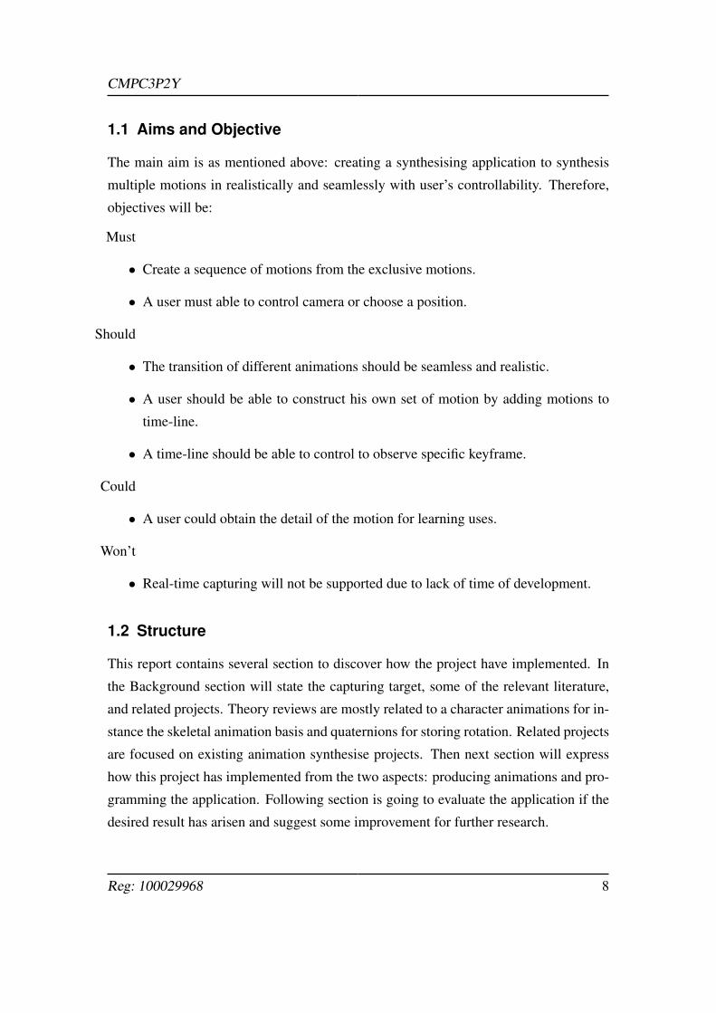
1.1 Aims and Objective
The main aim is as mentioned above: creating a synthesising application to synthesis
multiple motions in realistically and seamlessly with user’s controllability. Therefore,
objectives will be:
Must
• Create a sequence of motions from the exclusive motions.
• A user must able to control camera or choose a position.
Should
• The transition of different animations should be seamless and realistic.
• A user should be able to construct his own set of motion by adding motions to
time-line.
• A time-line should be able to control to observe specific keyframe.
Could
• A user could obtain the detail of the motion for learning uses.
Won’t
• Real-time capturing will not be supported due to lack of time of development.
1.2 Structure
This report contains several section to discover how the project have implemented. In
the Background section will state the capturing target, some of the relevant literature,
and related projects. Theory reviews are mostly related to a character animations for in-
stance the skeletal animation basis and quaternions for storing rotation. Related projects
are focused on existing animation synthesise projects. Then next section will express
how this project has implemented from the two aspects: producing animations and pro-
gramming the application. Following section is going to evaluate the application if the
desired result has arisen and suggest some improvement for further research.
Reg: 100029968 8
CMPC3P2Y
2 Background
This section will cover fundamental principles of the project. For instance the program
design concept, the capturing target, several theories which will be involved in Imple-
mentation section and also given research of related projects especially synthesising
animations.
2.1 Model-View-Controller
A concept of Model-View-Controller(MVC) has introduced by Reenskaug (1979). The
MVC paradigm assigns objects in the software one of three roles: model, view, con-
troller.
• Model represents data or even activity. In this project model refers to the data of
3D character models, animations and its constructing OpenGL code. The model
does not depend on the controller or the view.
• View visualises the state of the model and sends user action to the controller.
• Controller offers facilities to change the state of the model. For instance, con-
troller provides tools to trigger appropriate change to the model and make the
view to display the updated state based on the user input
This concept can reduce unnecessary dependences, thus the codes will be less errors
and easier to maintain; the model is encapsulated so that is to say model classes have
become reusable without modification. Therefore we are going to borrow the concept
of MVC to increase the flexibility of the application.
2.2 Kendo
Kendo is a Japanese martial art which trains the mind and body and cultivates one’s
character through one-to-one combat using a bamboo sword while wearing traditional
clothing and protective equipment. In addition to that, kendo have some several se-
quences or forms of movement, which is known as Kata. Many martial arts have its
kata. As Miller (2011) statement from his book, Drills:
Reg: 100029968 9
CMPC3P2Y
Fighting is inherently conservative and this shows in martial arts. Fighting
is dangerous. People get hurt and killed. For everything that might work
there are a hundred things that seem like a good idea that can lead to a
messy death. We have kata and tradition NOT because people are stuck in
tradition but because when people consistently survived it was considered
imperative to remember how to model it.
Therefore, remembering kata could be one of the really important factor of learning
Kendo kata includes Uchitachi, who attacks first as a pupil, and Shitachi, who counter-
attacks as a teacher. Yet the main purposes of the kata is discussed above, there is one
more important factor which is the kendo kata is used to pass the kendo dan (rank) exam.
Hakudo (2013) claims that the techniques of simply flight is widely spread, however,
the importance of kata and its techniques seems underestimated. Therefore, the project
could help to learn kata and it might improve understanding of hidden aspect of the
martial art to learners.
2.3 Theory reviews
2.3.1 Character animation
According to B.J.H. van Basten (2010), generation human animation can be classified
into three classes and each having its own advantages and disadvantages. The first ap-
proaches is procedural; which create its movement from scratch by using algorithms
based on empirical and biomechanical concepts. The one of pros of the technique is
really useful for controllability. However, this type of animations are generally not
perceived as realistic. Second technique is physics-based; generate locomotion using
dynamics and physical properties of the body. This type of animations tend to more
realistic by applying realistic torques on the joints, yet it provides less control than pre-
vious techniques and it could be computationally expensive. Last but not least class
is example-based approaches; reuse existing motions to generate a clip of movement.
Moreover, B.J.H. van Basten (2010) mentioned that the example-based can be subdi-
vided into two main approaches: motion concatenation and motion parametrization.
The former stitch clips of motions together to generate and usually it yields more natu-
Reg: 100029968 10
CMPC3P2Y
ral animation. On the other hand, motion parametrization approach interpolate between
existing motions to generate motions corresponding to specific parameters and it offers
higher level of control than another.
2.3.2 Quaternions
Quaternions compose a set of four numbers that are used to represent rotation. There
are two components in each quaternions: first part is a vector component which consists
of three values x, y and z, and a scaler value which is usually represented as w. The
scaler value represent the angle of rotation in the form cos(angle/2).
There are several reasons that quaternions should be used in the project to rotate
characters:
1. Quaternions are not susceptible to gimbal lock, a phenomenon in which an object
loses the ability to rotate on one of its three axis. Gimbal lock shows its face when
tow axes point in the same direction. This causes all sorts of problems.
2. They have the ability to have smooth, interpolated rotation. It is much easier to
interpolate rotations using quaternions rather than matrices, resulting in smoother
animations.
3. They take less room than a rotation matrix, and some operations are cheaper to
perform on quaternions in terms of processor cycles.
Pipho (2003) mentions quaternions can be treated simply as four-dimentional vectors
for the purpose of addition, subtraction, and scaler multiplication.
q =[4 3 2 1
]p =
[9 8 7 6
]q+ p =
[13 11 9 7
]3q =
[12 9 6 1
]Importantly, the quaternion does not represent a rotation quaternion, unless it is a unit
quaternion; it is the same as a unit vector. The unit quaternion has a magnitude of the
vector, and unless it has a magnitude of one it does not represent a rotation.
Reg: 100029968 11
CMPC3P2Y
Multiplying two quaternions together has the same output as multiplying correspond-
ing rotation matrices, however it is computationally less. The multiplication for quater-
nion is shown in below. (· refers to the dot product, × refers to the cross product)
p = [m,u] q = [n,v]
qp = [mn− v ·u,nu+mx+(v×u)]
Moreover, quaternions can ve rotate vectors or other quaternions. The formula below
can be used for both rotating quaternions and rotation vectors by other quaternions. (p
can be a quaternion or a vector)
p′ = q(p)(∼ q)
Although discussed above, quaternions can be used for representing a rotation, how-
ever, it is not always feasible to specify a quaternion directly. Therefore, quaternions
should be converted to rotation matrices or a set of Euler angles in terms of calculating
rotation with quaternion from the programmers point of view. Thus, quaternions have
mainly used in the project to representing rotation of 3D character.
2.3.3 Interpolation
As we discussed about quaternions above, it might be time to talk about interpolation.
Interpolation is very important when working with 3D models. For instance, there if
some projects contains some enemies who patrol and area, back and forth. The enemies
patrol along to the path, which is given from a start point to an end point and the time it
should take for the enemy to get from one to the other. Since only the start and end points
have been specified, the positions of the enemy at any given time might not be found
easily. Using interpolation, the position could calculate where the enemies should be, no
matter how much time has elapsed since they stared patrolling. Interpolation means that
estimation of an unknown quantity between two known quantities: the start point and
the end point. This can help produce smooth animation since it can produce an unlimited
number of midpoints, allowing the moves between point to be very small value and it
should be imperceptible to users. There are two main types of quaternion interpolation:
Reg: 100029968 12
CMPC3P2Y
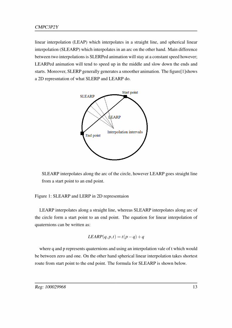
linear interpolation (LEAP) which interpolates in a straight line, and spherical linear
interpolation (SLEARP) which interpolates in an arc on the other hand. Main difference
between two interpolations is SLERPed animation will stay at a constant speed however;
LEARPed animation will tend to speed up in the middle and slow down the ends and
starts. Moreover, SLERP generally generates a smoother animation. The figure[1]shows
a 2D represntation of what SLERP and LEARP do.
SLEARP interpolates along the arc of the circle, however LEARP goes straight line
from a start point to an end point.
Figure 1: SLEARP and LERP in 2D representaion
LEARP interpolates along a straight line, whereas SLEARP interpolates along arc of
the circle form a start point to an end point. The equation for linear interpolation of
quaternions can be written as:
LEARP(q, p, t) = t(p−q)+q
where q and p represents quaternions and using an interpolation vale of t which would
be between zero and one. On the other hand spherical linear interpolation takes shortest
route from start point to the end point. The formula for SLEARP is shown below.
Reg: 100029968 13
CMPC3P2Y
SLEARP(q, p, t) =q∗ sin(θ(1− t))+ p∗ sin(θ t)
sin(θ)
2.3.4 Skeletal animation
As Pipho (2003) mentioned that in almost any new modern 3D game engines use skele-
tal animation system. According to Pipho (2003), one of the first popular games, which
used skeletal animation, was Half-Life. Skeletal animation is the use of ’bones’ to ani-
mate a model rather than editing and moving each vertex or face manually. Each vertex
is attached to a bone or in some cases multiple bones, A bone or joint is simply a control
point for a group of vertices. These are similar in concept to joints in our own bodies,
such as knee or wrist joint. When you move up right wrist, the position of right elbow
also moves: when the bone moves, every vertex attached to it moves as well, This helps
the model movement appropriately, since movement from some part of body affects
other parts of the body as mentioned above. Skeletal animation has many advantages
over the traditional vertex animation as Pipho (2003) mentioned. Firstly, it can increase
realism: skeletally animated characters tend to move much more realistically and often
appear to interact better with their surroundings than traditional models. If traditional
key-frame animation is used, the game will linearly interpolate between two poses, that
is to say however, in this case the joints do not actually rotate which can be problem
because living organism move in rotational ways. Secondly, skeletal animation take up
less storage space; rather than storing a set of vertices for each frame, all that needs to
be stored is the translation and rotation of the bones. On the other hand, there is dis-
advantages such as, the concept of skeletal animation can be harder to understand and
implement, than keyframed animation. When skeletal animation is applied, the vertices
of meshes from 3D character needs to be attached to the hierarchical bones with calcu-
lated weight. The weight represents how many vertices for the bone and how do they
affect their position and orientation by another bones movement. The skinning detail
will be discussed in the implementation section.
Pejsa and Pandzic (2010) have summarised when the skeletal animation is used, the
skeleton are hierarchically constructed with bones and joints. Joins stores transforma-
tion and the parameters which constructed with a 3D vector for the position and Euler
Reg: 100029968 14
CMPC3P2Y
angles or quaternion to represent the rotation of the joint.
2.3.5 MD5
As the importance of quaternions has discussed above, it might be time to talk about 3D
model format for the project. We have used MD5 model format which comes from first
person shooter game known as Doom 3 (2004). The format stores the mesh data and an-
imation data individually in separated files, and they are human readable as ASCII files.
David (2005) mentions that model’s geometric data are stored in *.md5mesh files and
animations are stored in *.md5anim files. The key features of the format are it supports
skeletal animation and orientation are calculated by quaternions. The .md5mesh files
stores geometric data of the 3D character. It should support one or multiple meshes and
.md5anim store information about skeletal animation of MD5 models David (2005).
David (2005) has produced a MD5 viewer application which handle both MD5 mesh
and its animations and the project can be download from his website as it is MIT licensed
and presented for educational uses. His framework contains over five classes which
represents MD5 model and the detail of classes are:
• Md5Object
It stores all the Md5Model. This class covers all information of meshes and ani-
mations loaded.
• Md5Model
Each Md5Model has a list of Md5Mesh and a list of Md5Animations.
• Md5Mesh
Md5Mesh class stores geometric data of the meshes. Each mesh have its proper
data, such as a shader name, vertex weight, triangle and vertices.
• Md5Animations and Md5Skelton
Skeleton hierarchy for each joint for motion, a bounding box for each keyframe of
animation, and a list of frames data are stored in this class. It contains Md5Skeleton
object which represents the baseframe skeletal hierarchy data and these data will
Reg: 100029968 15
CMPC3P2Y
be computed by Md5Animations class to produce the appropriate positions and
orientation of skeleton for the keyframe by using the list of frames data.
The main disadvantage of the application is that does not support applying multiple
animations seamlessly. Therefore we decided implement time-line features to achieve
creating the sequence of kata which is going to be mentioned in later section.
2.4 Related works
2.4.1 Parametrising Blends
Parametrised blending of captured examples techniques have been pioneered by Charles Rose
and F.Cohen (1998), which are known as verbs and adverbs system. Rose and his group
proposed a fundamental that allows interpolate between similar motions of verb and ad-
verbs. For instance, the verbs motion contains run and jump and the adverbs contains
happy and sadly which affect the verb actions. The basic of actions were dynamically
stored in data structure for seamless transitioning; the transition was constructed by
applying a radial basis technique and scaling some of the animation frames in terms of
time. This work has assumed that the example motions have been identified and cropped
from the original data set.
2.4.2 Motion Graph
Motion capture is a technique to seamlessly connect a motion in database using a tran-
sition. During the process, a graph structure will be produced which is called motion
graph. In the graph, edges correspond to motion clips and nodes represent as points that
connect to the clip. This technique is inspired by the video texture, which is used to
maintain the original motion sequences and pay back in non repetitive streams. Motion
capture is often used in real-time application and off-line sketch-cased motion synthesis
to produce character’s animation. One of the most influential work has been published
by Lucas Kovar (2002). In the paper, there are three research work that marked as the
original motion graph in the history of computer graphics. These three approached are
proposed by Arikan and Forsyth (2002) and Lee (2002). Those approaches share the
Reg: 100029968 16
CMPC3P2Y
same basic thought that is developed a graph from motion database and examine the
graph to generate a transition, although they have used different techniques in some
cases, such as generating transition, determining the distance metrics through the graph.
For instance Arikan and Forsyth (2002) mentioned using a hierarchy of motion graphs
for searching randomly of motions with required features; motion duration.
Motion graph technique divide motions into several groups by similarity of behaviour,
and then use the groups to create interpolation and smooth transition. Kwon and Shin
(2005) has implemented semi-automated motion graph system for locomotion. Treuille
and Z.Popovi (2007) employed simplified graph structure to create real-time animation,
they divide animation into short clips and arrange them into nodes in graph and blend
them to generate locomotion in real-time. They have borrowed a low dimensional basic
representation to guide the virtual character to the given goal. The goal is drawn a sketch
of a path, and acting our a desired motion in front of the video camera.
Pejsa and Pandzic (2010) have done further research of parametric motion, especially
focuses on the example-based animation synthesising. They introduce a solution for
continuous motions by searching the most similar motions to be blended. However, the
produced sequence of motion might have some artefacts and be unsuitable because of
searching appropriate animations in the motion graph is computationally expensive.
2.4.3 Footprint-driven animation authoring
3D characters constantly move through highly constrained virtual environment in mod-
ern games. Particularly if the character walks in indoor environment, there might be
tables and chair in narrow corridors, and the it is crucial that there are no collisions
between the character and walls or furniture. In such case, a path-based locomotion
locomotion is not sophisticated enough because if the character collied the objects, an-
other motions need to be taken such as sidestepping or backward. B.J.H. van Basten
(2010) claim synthesise locomotion based on the actual placement of footsteps in the
environment, and this sort of problem is known as stone stepping. The popular strat-
egy is that provide user to author the character behaviours.Shawn Singh and Faloutsos
(2011) have create the application which takes the Center-Of-Mass, which refers to the
unique point ere the weighted relative position of the distributed mass sums to zero, tra-
Reg: 100029968 17

CMPC3P2Y
jectory and footprints locations as input then it produces an efficient strategy to calculate
the minimised energy expenditure duration for each footsteps. B.J.H. van Basten (2010)
also look into the strategy that, they have used an efficient nearest neighbour approach
and warp the resulting animation; it adheres to both temporal constraints and spatial,
which are generated by employing time warping and Inverse Kinematics techniques.
Reg: 100029968 18
CMPC3P2Y
3 Implementation
This section will explain how the project has been implemented. First part expresses
how we have produced the MD5 models and second part shows how the project has
been designed and implemented.
3.1 Motion production
3.1.1 EVaRT
Eagle Star Optical Motion Capture system was the hardware made available to this
project to capture motions. To obtain the data, EVaRT soft ware was used in conjunction
with the hardware.
• Calibration
This session will provide an overview of how to calibrate the MoCap system
using the software called EVaRT. The software was used in conjunction with the
aforementioned hardware.
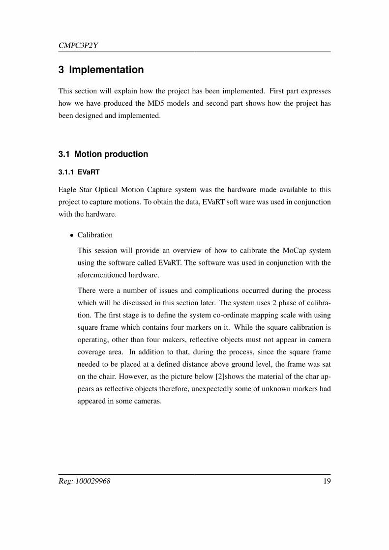
There were a number of issues and complications occurred during the process
which will be discussed in this section later. The system uses 2 phase of calibra-
tion. The first stage is to define the system co-ordinate mapping scale with using
square frame which contains four markers on it. While the square calibration is
operating, other than four makers, reflective objects must not appear in camera
coverage area. In addition to that, during the process, since the square frame
needed to be placed at a defined distance above ground level, the frame was sat
on the chair. However, as the picture below [2]shows the material of the char ap-
pears as reflective objects therefore, unexpectedly some of unknown markers had
appeared in some cameras.
Reg: 100029968 19
CMPC3P2Y
Square calibration, some cameras are capturing unexpected marker.
Figure 2: Square Calibration
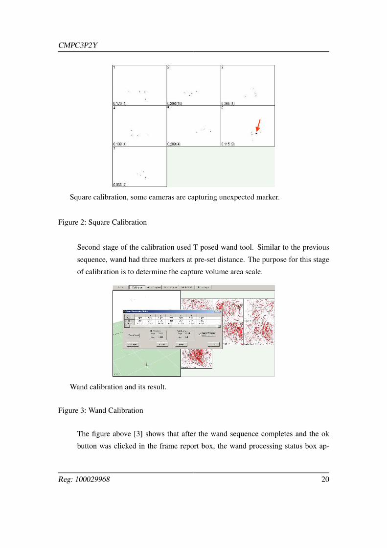
Second stage of the calibration used T posed wand tool. Similar to the previous
sequence, wand had three markers at pre-set distance. The purpose for this stage
of calibration is to determine the capture volume area scale.
Wand calibration and its result.
Figure 3: Wand Calibration
The figure above [3] shows that after the wand sequence completes and the ok
button was clicked in the frame report box, the wand processing status box ap-
Reg: 100029968 20
CMPC3P2Y
pears. Ideally the calibration should have between +/-0.5 deviation values and the
average of 3D residuals should have been less than at least 0.35. Otherwise the
amount of post process would be increased terribly. A number of trials with dif-
ferent configurations and camera setting is critical for satisfactory results. Once
the calibration has done, actual capture stage will be followed. However, since
the camera settings are really sensitive in terms of oscillation, it was worth to cap-
ture without vehement movements: if the actor jumps and the camera and tripod
moves even slightly due to the oscillation, the calibration would break down.
• Capturing
Actor wears costume with a number of makers to capture its set of motions. Fol-
lowing 3D modelling conversations, the first capture must be that of a T pose since
the pose will be used to assign maker names in the model edit stage. In terms of
length of each motion should be less than 10 seconds otherwise the possibility of
losing some data could be hugely increased.
• Post processing
The large amount of time has spent on this stage. Although the satisfactory result
of the calibration helps to reduce the time to spend, some errors such as miss-
ing data, scattering data and ghost makers tend to be happened. To check if the
specific maker data has been preserved properly, we needed to go through from
the beginning to at the end of motion, or specified area which might be used for.
When the data has been perfectly captured, the XYZ graph shows smooth curves
or lines, however, there were likely a break in the data signal of the selected
marker. The break of the signal could be completely missed or confused by the
system during capturing. If the data of marker in the break was missed the maker
would be disappear from 3D view, yet if the data was just confused to other mak-
ers data, the maker would stay in the view. In such case, by selecting the other
maker that has replaced the marker previously in place, the graph data show a
section of track that should be in the track of the marker. To replace, the switched
data need to be selected and choose the markers then exchanged the selected range
of data. After the process, missing data should be back to the marker signal and
Reg: 100029968 21
CMPC3P2Y
then we need to join the broken signal either Linear join or Cubic join depending
on the situation. Edit tools panel provides copy and past functions which reduce
the amount of time to do the interchanging. Moreover, there were still some other
case: the data of the marker was scattered. If the marker’s data was fragmented,
the data was collected from several undefined markers to reconstruct the broken
part of the signal. One of the collected data was sometimes just a dot. Although
the amount of data was very little from with the dot, we could join the signal
because of the dot which located in the middle of the break relayed two signals.
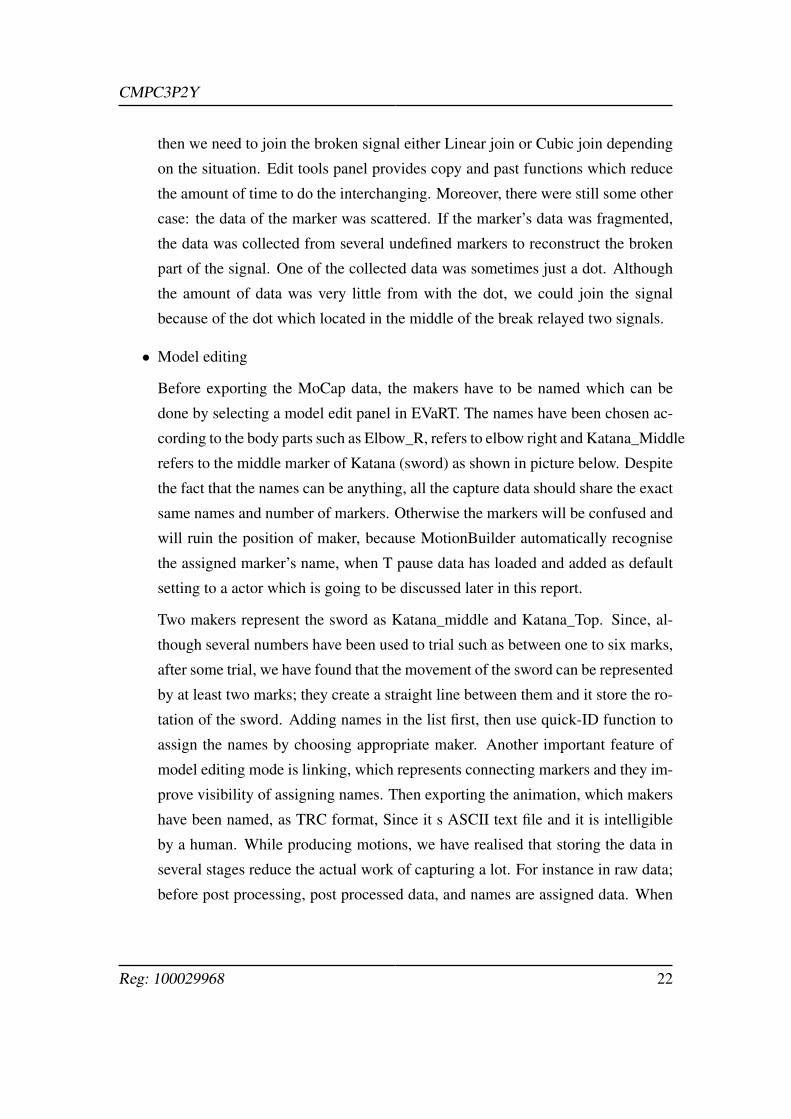
• Model editing
Before exporting the MoCap data, the makers have to be named which can be
done by selecting a model edit panel in EVaRT. The names have been chosen ac-
cording to the body parts such as Elbow_R, refers to elbow right and Katana_Middle
refers to the middle marker of Katana (sword) as shown in picture below. Despite
the fact that the names can be anything, all the capture data should share the exact
same names and number of markers. Otherwise the markers will be confused and
will ruin the position of maker, because MotionBuilder automatically recognise
the assigned marker’s name, when T pause data has loaded and added as default
setting to a actor which is going to be discussed later in this report.
Two makers represent the sword as Katana_middle and Katana_Top. Since, al-
though several numbers have been used to trial such as between one to six marks,
after some trial, we have found that the movement of the sword can be represented
by at least two marks; they create a straight line between them and it store the ro-
tation of the sword. Adding names in the list first, then use quick-ID function to
assign the names by choosing appropriate maker. Another important feature of
model editing mode is linking, which represents connecting markers and they im-
prove visibility of assigning names. Then exporting the animation, which makers
have been named, as TRC format, Since it s ASCII text file and it is intelligible
by a human. While producing motions, we have realised that storing the data in
several stages reduce the actual work of capturing a lot. For instance in raw data;
before post processing, post processed data, and names are assigned data. When
Reg: 100029968 22
CMPC3P2Y
Twenty three names have been given as in right hand side. And Quick ID has se-
lected to assign the names to the certain marker.
Figure 4: Model Edit
some data has some problem which has arisen in after exporting the data which
names are assigned appropriately. However, some markers are not post processed
properly and although the signal looks fixed, the signal is mixed up and confused
with several markers. In such case, we needed to do the process from the begin-
ning, and we would have spent large amount of time to calibrate again and again
if the data has been overwritten after model edited.
3.1.2 Modelling
As the kendo kata need two character, we have planned to creates two 3D character to
represent each role for the sequence. Since the skeletal animation technique is used,
applying several 3D model refers to change the mesh of the character only; not altering
entire mesh and animation, as long as same conventional skeleton is used they can be
reused by several 3D characters.
• skeleton
Reg: 100029968 23
CMPC3P2Y
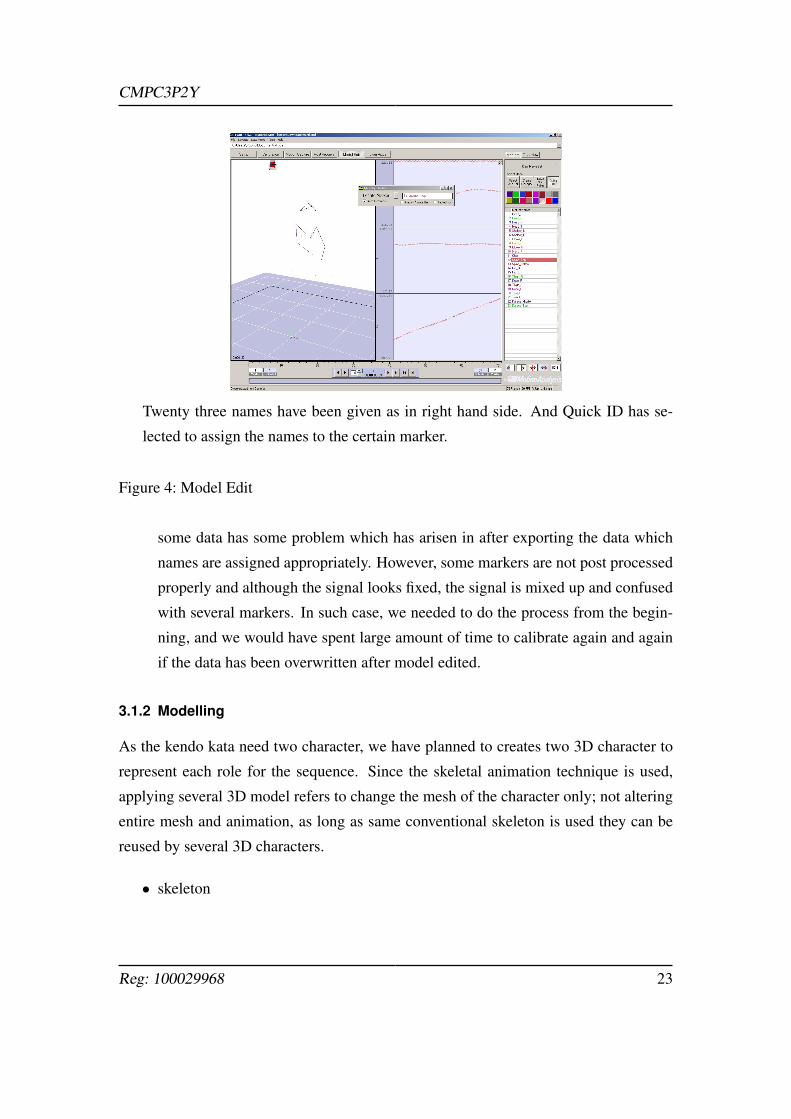
Since this project has employed skeletal animation, the 3D character need to have
a skeleton. The skeleton was one of the template skeleton from a software called
MotionBuilder. Since the template skeleton was used, we could able to charac-
terise the 3D model data easily. However, the skeleton does not contain hip joint
as default, therefore, an extra joint needs to be created to keep the convention.
The template skeleton from MotionBuilder which contains conventional names of
joints.
Figure 5: Skeleton
A OBJ file of model and the skeleton have different size and pose, the skeleton
needs to be aligned in terms of rotating joints and scaling to fitting into static OBJ
model character as closely as possible.
• Skinning Once the skeleton was aligned correctly to the static model the mesh
of the model need to be assigned to the skeleton which is known as skinning.
This could be done in the function of 3DS Max. Select the mesh which you
would like to perform and choose ’skins’ in the modifier panel, then the all the
bones of the skeleton needed to be chosen. When the initial skinning has done,
we should check the quality of the process; determine if the weight of bones and
Reg: 100029968 24
CMPC3P2Y
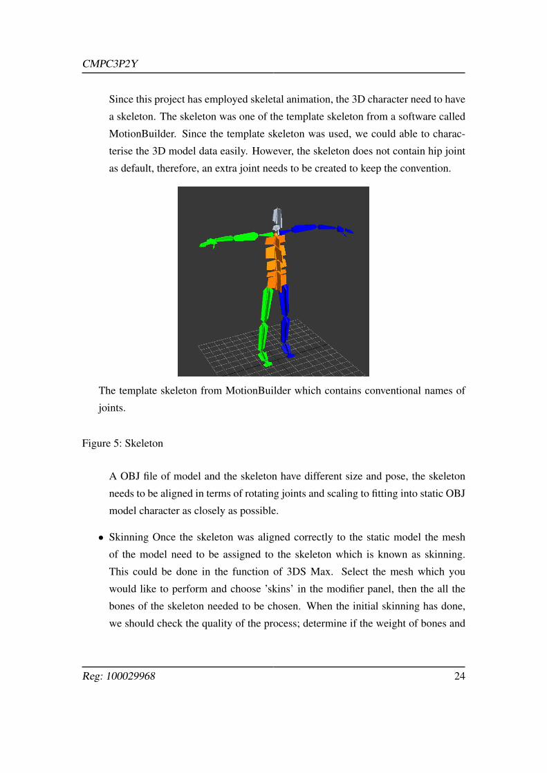
joins were correctly assigned or not. To check this, try to rotate each limbs, and if
the weight of the bone was wrong undesirable vertices of the mesh also affected.
For instance, when the right thigh bone was rotated to outside of the body based
on the hip joints, only the right leg of mesh should be affected, however, due to
the initial pose of the model stands upright with legs located closely, the other side
of the mesh also assigned to the right thigh bone and if the bone moves the mesh
also affected. Therefore, we had to modify the weight of each bones by painting
weight tool. The red dot on the vertex indicates strong dependency to the selected
bone, blue represents less dependency and the orange dot refers to blended. As
the picture shows the right thigh bone affects some of the vertexes of the mesh
around the left thigh which we do not desire.
Although the right thigh bone is rotated some of the vertexes of left thigh are influ-
enced.
Figure 6: Paint weights
Reg: 100029968 25
CMPC3P2Y
3.1.3 MotionBuilder
To export the captured data into Md5 format, they have to be applied to a 3DS Max
Skeleton and the MotionBuilder was used to connect the skeleton and the animations.
Motion builder’s features are mainly controlling over the animations and baking the
capture data into the skeleton. This session will discuss about processes.
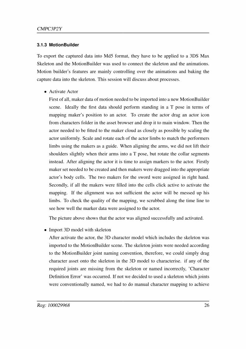
• Activate Actor
First of all, maker data of motion needed to be imported into a new MotionBuilder
scene. Ideally the first data should perform standing in a T pose in terms of
mapping maker’s position to an actor. To create the actor drag an actor icon
from characters folder in the asset browser and drop it to main window. Then the
actor needed to be fitted to the maker cloud as closely as possible by scaling the
actor uniformly. Scale and rotate each of the actor limbs to match the performers
limbs using the makers as a guide. When aligning the arms, we did not lift their
shoulders slightly when their arms into a T pose, but rotate the collar segments
instead. After aligning the actor it is time to assign markers to the actor. Firstly
maker set needed to be created and then makers were dragged into the appropriate
actor’s body cells. The two makers for the sword were assigned in right hand.
Secondly, if all the makers were filled into the cells click active to activate the
mapping. If the alignment was not sufficient the actor will be messed up his
limbs. To check the quality of the mapping, we scrubbed along the time line to
see how well the marker data were assigned to the actor.
The picture above shows that the actor was aligned successfully and activated.
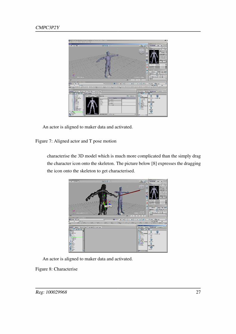
• Import 3D model with skeleton
After activate the actor, the 3D character model which includes the skeleton was
imported to the MotionBuilder scene. The skeleton joints were needed according
to the MotionBuilder joint naming convention, therefore, we could simply drag
character asset onto the skeleton in the 3D model to characterise. if any of the
required joints are missing from the skeleton or named incorrectly, ’Character
Definition Error’ was occurred. If not we decided to used a skeleton which joints
were conventionally named, we had to do manual character mapping to achieve
Reg: 100029968 26
CMPC3P2Y
An actor is aligned to maker data and activated.
Figure 7: Aligned actor and T pose motion
characterise the 3D model which is much more complicated than the simply drag
the character icon onto the skeleton. The picture below [8] expresses the dragging
the icon onto the skeleton to get characterised.
An actor is aligned to maker data and activated.
Figure 8: Characterise
Reg: 100029968 27
CMPC3P2Y
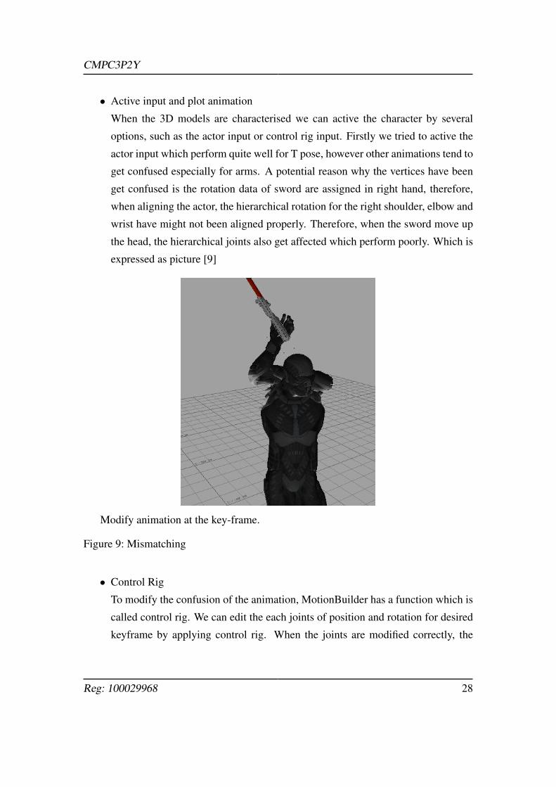
• Active input and plot animation
When the 3D models are characterised we can active the character by several
options, such as the actor input or control rig input. Firstly we tried to active the
actor input which perform quite well for T pose, however other animations tend to
get confused especially for arms. A potential reason why the vertices have been
get confused is the rotation data of sword are assigned in right hand, therefore,
when aligning the actor, the hierarchical rotation for the right shoulder, elbow and
wrist have might not been aligned properly. Therefore, when the sword move up
the head, the hierarchical joints also get affected which perform poorly. Which is
expressed as picture [9]
Modify animation at the key-frame.
Figure 9: Mismatching
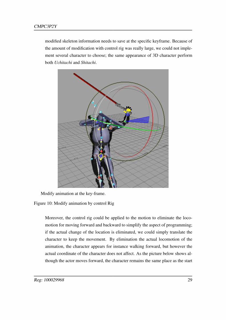
• Control Rig
To modify the confusion of the animation, MotionBuilder has a function which is
called control rig. We can edit the each joints of position and rotation for desired
keyframe by applying control rig. When the joints are modified correctly, the
Reg: 100029968 28
CMPC3P2Y
modified skeleton information needs to save at the specific keyframe. Because of
the amount of modification with control rig was really large, we could not imple-
ment several character to choose; the same appearance of 3D character perform
both Uchitachi and Shitachi.
Modify animation at the key-frame.
Figure 10: Modify animation by control Rig
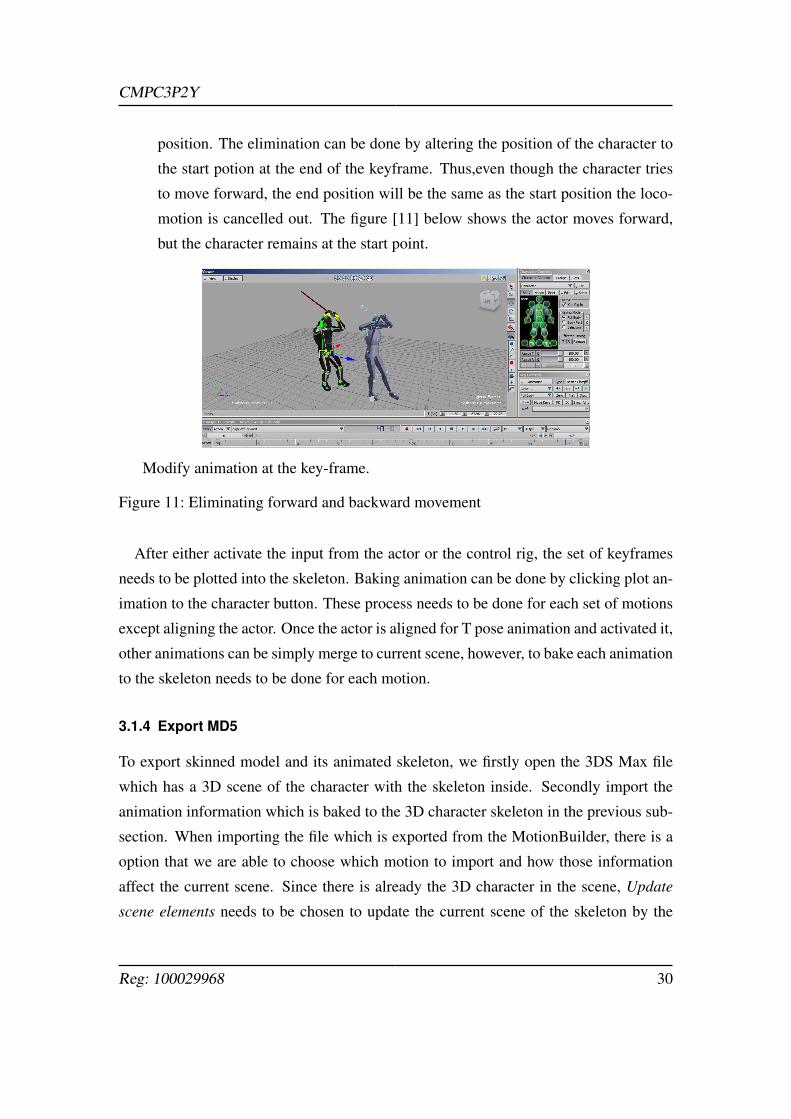
Moreover, the control rig could be applied to the motion to eliminate the loco-
motion for moving forward and backward to simplify the aspect of programming;
if the actual change of the location is eliminated, we could simply translate the
character to keep the movement. By elimination the actual locomotion of the
animation, the character appears for instance walking forward, but however the
actual coordinate of the character does not affect. As the picture below shows al-
though the actor moves forward, the character remains the same place as the start
Reg: 100029968 29
CMPC3P2Y
position. The elimination can be done by altering the position of the character to
the start potion at the end of the keyframe. Thus,even though the character tries
to move forward, the end position will be the same as the start position the loco-
motion is cancelled out. The figure [11] below shows the actor moves forward,
but the character remains at the start point.
Modify animation at the key-frame.
Figure 11: Eliminating forward and backward movement
After either activate the input from the actor or the control rig, the set of keyframes
needs to be plotted into the skeleton. Baking animation can be done by clicking plot an-
imation to the character button. These process needs to be done for each set of motions
except aligning the actor. Once the actor is aligned for T pose animation and activated it,
other animations can be simply merge to current scene, however, to bake each animation
to the skeleton needs to be done for each motion.
3.1.4 Export MD5
To export skinned model and its animated skeleton, we firstly open the 3DS Max file
which has a 3D scene of the character with the skeleton inside. Secondly import the
animation information which is baked to the 3D character skeleton in the previous sub-
section. When importing the file which is exported from the MotionBuilder, there is a
option that we are able to choose which motion to import and how those information
affect the current scene. Since there is already the 3D character in the scene, Update
scene elements needs to be chosen to update the current scene of the skeleton by the
Reg: 100029968 30
CMPC3P2Y
skeleton which includes the animations. The export format of MD5 is not built in the
3DS Max software, therefore we have borrowed a 3DS Max executable script which is
available at KatsBits (2015) website. The .md5mesh file needs to be exported only once
for the model and the .md5anim files have been exported respectively.
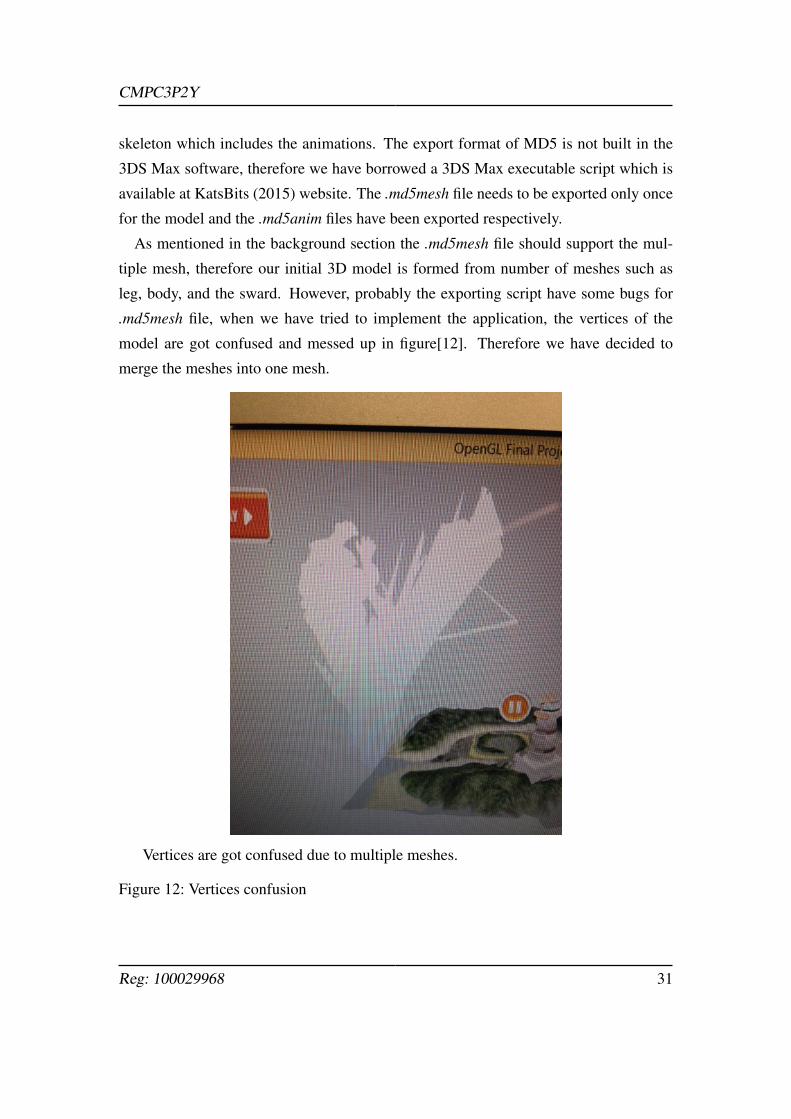
As mentioned in the background section the .md5mesh file should support the mul-
tiple mesh, therefore our initial 3D model is formed from number of meshes such as
leg, body, and the sward. However, probably the exporting script have some bugs for
.md5mesh file, when we have tried to implement the application, the vertices of the
model are got confused and messed up in figure[12]. Therefore we have decided to
merge the meshes into one mesh.
Vertices are got confused due to multiple meshes.
Figure 12: Vertices confusion
Reg: 100029968 31
CMPC3P2Y
3.2 Programming
The application is designed to users to be play the Kendo kata and show the tip for each
animation, and also user can change the point of view to help understanding of motions.
In addition to that, there is a another feature that users are able to create own set of kata
by synthesising several simpler animations into it. It is written by C++ and PpenGL to
display 3D environment and 2D user interface. There is a frameworks for this project
which is produced by Song (2010) which contains several classes to achieve the Model-
View-Controller(MVC) concept. The basic description of MVC is mentioned in the
Background section.
3.2.1 Frameworks
The frameworks of the project was presented by Song (2010) contains classes:
• Procedure and Controller class
Although Procedure is not the actual class, it detects user inputs and it triggers to
call some methods of the Controller class. For instance if user clicks left mouse
button in the application, Procedure detects left mouse button is pressed mes-
sage from Win32, then it calls lButtonDonw() method which updates ModelGL’s
mouse coordinates and left mouse button status.
• ControllerGL class
This class inherits from the Contoller class as you can see in class diagram. It have
methods which are overridden from the Contoller class and specified appropriate
reaction to the user input. Also it contains class pointers of ModelGL and ViewGL
to passing through user input to each class.
• ModelGL class
This class responses the application’s data such as detail of opengGL specific
code. It obtains pointers of GUI class and SceneModel class for instance MD5
model data. ModelGL handles rendering the scene by calling a method draw()
and the current scene data is stored in SceneModel and GUI separately. First
class SceneModel loads both .md5mesh and .md5anim data and it handle these
Reg: 100029968 32
CMPC3P2Y
data to represents the both 3D and 2D current scene. GUI class mainly draws the
elements of graphical user interface (GUI). All the texture of GUI are loaded from
PNG format pictures when the GUI class is created.
• ViewGL class
ViewGL handles to current rendering and device contexts. The swapBuffers()
method exchanges the front and back buffers of the display and it is triggered
if the draw() method in ModelGL is called throughout the ControllerGL class.
Those classes represent main frame of the application. In addition to that Camera
class is used for handling camera; the view point of the user. When the user desire
to change the camera point by pressing specified keyboard or selecting by the GUI,
Procedure detects the input then methods in the Camera class are called.
3.2.2 GUI
The main functions of the application is playing the sequence of kata to learn. Users
should be able to play the sequence forward, backward and change the speed of the
movement from the several point of view. Also they can move around the seek-bar to
observe the detail of the motion at the keyframe.
Not only to achieve the functionalities but also to improve the appearance of the scene,
we have decided to implement the GUI in the same frame as 3D scene; the GUI textures
are more likely to float in front of the characters. Although We thought subdivide the
frames such as top frame for 3D scene and bottom frame for 2D scene might be more
clear for users to use the application, separating the frames implies the main frame
might be smaller, and that might be difficult to observe characters. Therefore, the both
3D scene and 2D scene are rendered in the same frame and using maximum window
size. The concept has come from a website called Youtube. There are so many tutorial
videos on the website and people tend to search the tutorial video when they would like
to learn something new, such as playing musical instrument, dancing, and even learning
martial arts Youtube (2015). Therefore, people might be get used to the structure of
Reg: 100029968 33
CMPC3P2Y
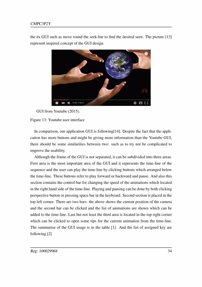
the its GUI such as move round the seek-bar to find the desired seen. The picture [13]
represent inspired concept of the GUI design.
GUI from Youtube (2015).
Figure 13: Youtube user interface
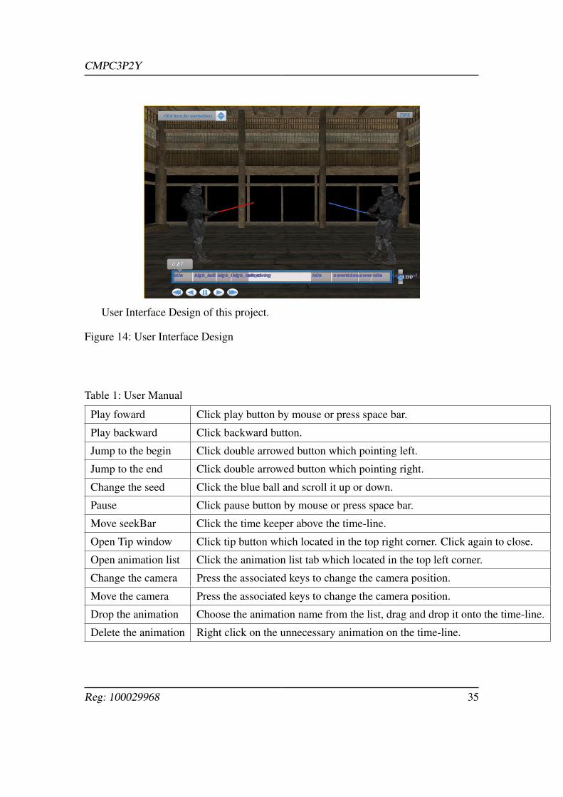
In comparison, our application GUI is following[14]. Despite the fact that the appli-
cation has more buttons and might be giving more information than the Youtube GUI,
there should be some similarities between two: such as to try not be complicated to
improve the usability.
Although the frame of the GUI is not separated, it can be subdivided into three areas.
First area is the most important area of the GUI and it represents the time-line of the
sequence and the user can play the time-line by clicking buttons which arranged below
the time-line. These buttons refer to play forward or backward and pause. And also this
section contains the control bar for changing the speed of the animations which located
in the right hand side of the time-line. Playing and pausing can be done by both clicking
perspective button or pressing space bar in the keyboard. Second section is placed in the
top left corner. There are two bars: the above shows the current position of the camera
and the second bar can be clicked and the list of animations are shown which can be
added to the time-line. Last but not least the third area is located in the top right corner
which can be clicked to open some tips for the current animation from the time-line.
The summarise of the GUI usage is in the table [1]. And the list of assigned key are
following [2]
Reg: 100029968 34
CMPC3P2Y
User Interface Design of this project.
Figure 14: User Interface Design
Table 1: User Manual
Play foward Click play button by mouse or press space bar.
Play backward Click backward button.
Jump to the begin Click double arrowed button which pointing left.
Jump to the end Click double arrowed button which pointing right.
Change the seed Click the blue ball and scroll it up or down.
Pause Click pause button by mouse or press space bar.
Move seekBar Click the time keeper above the time-line.
Open Tip window Click tip button which located in the top right corner. Click again to close.
Open animation list Click the animation list tab which located in the top left corner.
Change the camera Press the associated keys to change the camera position.
Move the camera Press the associated keys to change the camera position.
Drop the animation Choose the animation name from the list, drag and drop it onto the time-line.
Delete the animation Right click on the unnecessary animation on the time-line.
Reg: 100029968 35
CMPC3P2Y
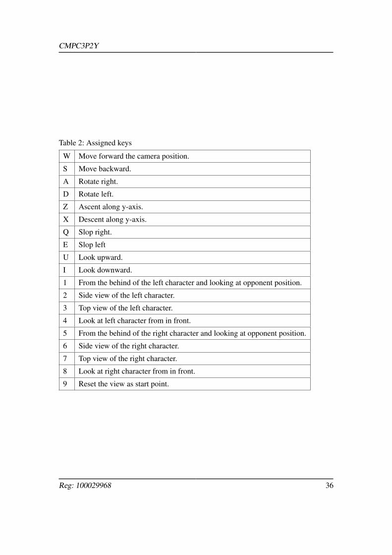
Table 2: Assigned keys
W Move forward the camera position.
S Move backward.
A Rotate right.
D Rotate left.
Z Ascent along y-axis.
X Descent along y-axis.
Q Slop right.
E Slop left
U Look upward.
I Look downward.
1 From the behind of the left character and looking at opponent position.
2 Side view of the left character.
3 Top view of the left character.
4 Look at left character from in front.
5 From the behind of the right character and looking at opponent position.
6 Side view of the right character.
7 Top view of the right character.
8 Look at right character from in front.
9 Reset the view as start point.
Reg: 100029968 36
CMPC3P2Y
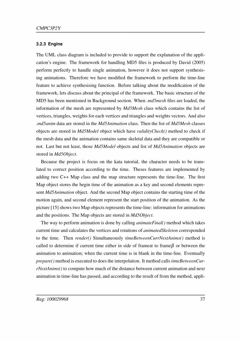
3.2.3 Engine
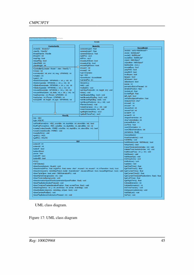
The UML class diagram is included to provide to support the explanation of the appli-
cation’s engine. The framework for handling MD5 files is produced by David (2005)
perform perfectly to handle single animation, however it does not support synthesis-
ing animations. Therefore we have modified the framework to perform the time-line
feature to achieve synthesising function. Before talking about the modification of the
framework, lets discuss about the principal of the framework. The basic structure of the
MD5 has been mentioned in Background section. When .md5mesh files are loaded, the
information of the mesh are represented by Md5Mesh class which contains the list of
vertices, triangles, weights for each vertices and triangles and weights vectors. And also
.md5anim data are stored in the Md5Animation class. Then the list of Md5Mesh classes
objects are stored in Md5Model object which have validityCheck() method to check if
the mesh data and the animation contains same skeletal data and they are compatible or
not. Last but not least, those Md5Model objects and list of Md5Animation objects are
stored in Md5Object.
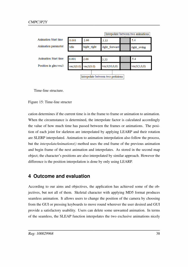
Because the project is focus on the kata tutorial, the character needs to be trans-
lated to correct position according to the time. Theses features are implemented by
adding two C++ Map class and the map structure represents the time-line. The first
Map object stores the begin time of the animation as a key and second elements repre-
sent Md5Animation object. And the second Map object contains the starting time of the
motion again, and second element represent the start position of the animation. As the
picture [15] shows two Map objects represents the time-line: information for animations
and the positions. The Map objects are stored in Md5Object.
The way to perform animation is done by calling animateFinal() method which takes
current time and calculates the vertices and rotations of animatedSkeleton corresponded
to the time. Then render() Simultaneously timeBetweenCurrNextAnims() method is
called to determine if current time either in side of frameα to frameβ or between the
animation to animation; when the current time is in blank in the time-line. Eventually
prepare() method is executed to does the interpolation. It method calls timeBetweenCur-
rNextAnims() to compute how much of the distance between current animation and nexr
animation in time-line has passed, and according to the result of from the method, appli-
Reg: 100029968 37
CMPC3P2Y
Time-line structure.
Figure 15: Time-line structer
cation determines if the current time is in the frame to frame or animation to animation.
When the circumstance is determined, the interpolate factor is calculated accordingly
the value of how much time has passed between the frames or animations. The posi-
tion of each joint for skeleton are interpolated by applying LEARP and their rotation
are SLERP interpolated. Animation to animation interpolation also follow the process,
but the interpolateAnimations() method uses the end frame of the previous animation
and begin frame of the next animation and interpolates. As stored in the second map
object; the character’s positions are also interpolated by similar approach. However the
difference is the position interpolation is done by only using LEARP.
4 Outcome and evaluation
According to our aims and objectives, the application has achieved some of the ob-
jectives, but not all of them. Skeletal character with applying MD5 format produces
seamless animation. It allows users to change the position of the camera by choosing
from the GUI or pressing keyboards to move round wherever the user desired and GUI
provide a satisfactory usability. Users can delete some unwanted animation. In terms
of the seamless, the SLEAP function interpolates the two exclusive animations nicely
Reg: 100029968 38
CMPC3P2Y
in general. The speed of sequence can be modified from as fast as twice to as slow as
half of original speed. In addition to that, it allows to reconstruct the sequence for the
character in the left hand side by adding animations from the list of animation. The
kendo kata contains two characters and they updates their time-line perspectively, and
for the default, those two sequence synchronised quite attractively as a tutorial applica-
tion. And also users can obtain the tips of the current playing animation for learning
purpose. Although, if the user reconstruct the sequence of the kata another character’s
sequence does not synchronised at all, the project has focused on providing educational
tutorial of martial arts, therefore, the project could have achieved the main functionality.
However there are also many limitations for the application. Following subsections will
argue the limitations and potential improvement of the application.
On the other aspect, the project provided great opportunity to learn a lot of theories
and practical experiences of developing the application. The fundamentally knowledge
of C++ and OpenGL have improved. Particularly working in a fully equipped motion
capture laboratory will be an priceless experience.
4.1 Limitation and Improvement
• No synchronisation of two charactersEven if the one of the time-line has updated by reconstructing, another does not
updated automatically and users are not allowed to edit another character’s time-
line. Due to the lack of time, we could not implement the function to switch
over the displaying time-line. It could be improved if the automated system for
synchronisation has been implemented for instance, if one of the swing animation
is added into the time-line, the counter attack animation should be inserted in
the appropriate time. However, the main aim of application is creating tutorial
software users might not do not need to create a time-line by themselves. Rather
than modifiability of the sequence, the application could have real-time capturing
system to evaluate users movement associated the sequence; more interactive, the
users can learn by observing motions then try to imitate the motion which will
be evaluated by the application in real-time. As Jamie Shotton and et al (2011)
have introduced body part recognition application using hardware called Kinect
Reg: 100029968 39
CMPC3P2Y
to capture in real-time.
• Create motion graph databaseOnly the LEARP interpolation between two animation has limitation to improve
its realistic. Therefore we could create set of animations for transition. The data
could be produced by capturing extra motions which may takes extra cost. Thus
as we have researched, the techniques of the motion graph can be used to generate
a transition database.
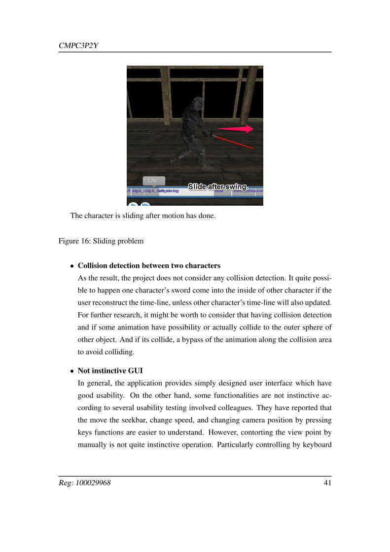
• Sliding transition for position interpolationThe SLEARP interpolation performs quite well in some case for instance between
rising up sward animation to moving forward animation, although when there is
such a long gap between two motions, it seems really awkward. Because the
theory which we have borrowed interpolates whenever two positions, for instance
after left character’s swing there is a large blank, which does not contain any
animations, and the function interpolate the start position of the swing to the next
start position of next animation along the duration between them. Therefore, if
the character actually swinging and it is being translated it looks fine, however,
the interpolation is still on the middle of the way to finish even after the swing
animation has finished, thus it looks that the character has stepped forward with
swing and then it paused until next animation stars but position of the character is
increasing therefore it looks sliding. This problem could be solved by employing
the footprint-driven synthesis techniques, however , purely due to lack of time we
could not able to implement the concept. This functionality should improve the
reality of character movement.
• Adding different appearance of 3D modelDue to the lack of time for development of the application, we could not imple-
ment several 3D characters to play with. Since skeletal animation is applied in
the software even the mesh of the 3D character changed the skeletal animation
works as long as same the skeleton is used. Kendo kata needs two characters,
changing characters should help users to understand the difference between two
the textitUchitachi and Shitachi.
Reg: 100029968 40
CMPC3P2Y
The character is sliding after motion has done.
Figure 16: Sliding problem
• Collision detection between two charactersAs the result, the project does not consider any collision detection. It quite possi-
ble to happen one character’s sword come into the inside of other character if the
user reconstruct the time-line, unless other character’s time-line will also updated.
For further research, it might be worth to consider that having collision detection
and if some animation have possibility or actually collide to the outer sphere of
other object. And if its collide, a bypass of the animation along the collision area
to avoid colliding.
• Not instinctive GUIIn general, the application provides simply designed user interface which have
good usability. On the other hand, some functionalities are not instinctive ac-
cording to several usability testing involved colleagues. They have reported that
the move the seekbar, change speed, and changing camera position by pressing
keys functions are easier to understand. However, contorting the view point by
manually is not quite instinctive operation. Particularly controlling by keyboard
Reg: 100029968 41
CMPC3P2Y
appears to be difficult to some of them who have not got any experience to con-
trol in 3D environment, such as playing game or so. To improve the usability, the
determination of camera direction should done by mouse input probably. As a
lack of experience in 3D environment rises the difficulty to control the camera by
rotating by three axes.
5 Conclusion
This report described the project undertaken. The project produce the simple martial
arts tutorial software, particularly focus on the Kendo’s kata sequences. The background
section looked at relevant projects especially in the field of synthesising motions and de-
scribed several theories which involved in the development process. In implementation
section is mostly dedicated ot the producing animations and aspects of programming.
Moreover, evaluation of outcome and some potential improvement of the application is
discussed.
Although the application has achieved the fundamental aims and objectives of the
projects, it should not be totally successful, since the application contains explicit prob-
lems such as low quality of transition in some case. However, we could use this project
for further research.
Reg: 100029968 42
CMPC3P2Y
References
Arikan, O. and Forsyth, D. A. (2002). Interactive motion generation from examples.
21(3):483–490.
B.J.H. van Basten, P.W.A.M. Peeters, A. E. (2010). The step space: example-based
footprint driven motion synthesis. Computer Animation and Virtual Worlds, 21:433–
441.
Charles Rose, B. B. and F.Cohen, M. (1998). Verbs and adverbs: Multidimensional
motion interpolation using radial basis functions. URL:http:// www.vuse.vanderbilt.
edu/ ~bobbyb/ pubs/ VandAdv98.pdf .
David, H. (2005). David henry’s homepage. URL:http:// tfc.duke.free.fr/ .
Hakudo, A. (2013). Hakudo-an, kendo research website. URL:http:// hakudoh.com/ wp/
study/ page_0502/ page_02.
Jamie Shotton, A. F. and et al (2011). Real-time human pose recognition in parts from
single depth images. URL:http:// sistemas-humano-computacionais.wdfiles.com/
local--files/ capitulo:modelagem-e-simulacao-de-humanos/ BodyPartRecognition%
20MSR%2011.pdf .
KatsBits (2015). Game making import/export scripts for blender, 3ds max, gmax.
URL:http:// www.katsbits.com/ tools/ .
Kwon, T. and Shin, S. Y. (2005). Motion modeling for on-line locomotion synthesis.
URL:http:// tclab.kaist.ac.kr/ ~taesoo/ locomotion/ locomotion_sca.pdf .
Lee, J. et, a. (2002). Interactive control of avaters animated with human motion
data. ISBN: 1-58113-521-1, DOI: 10.1145/566654.566607, URL:http:// dl.acm.org/
citation.cfm?doid=566570.566607 .
Lucas Kovar, Michael Gleicher, F. P. (2002). Motion graph. ACM Transactions on
Graphics (TOG)., 21:473–482.
Miller, R. (2011). Drills: Training For Sudden Violence.
Reg: 100029968 43
CMPC3P2Y
Pejsa, T. and Pandzic, I. (2010). State of the art in example-based motion synthesis for
virtual characters in interactive applications. Computer Graphic Forum, 29(1):202–
226.
Pipho, E. (2003). Focus on 3D models. Premier Press, a division of Course technology.
Reenskaug, T. (1979). A note on dynabook requirements. URL:http:// folk.uio.no/
trygver/ 1979/ sysreq/ SysReq.pdf .
Shawn Singh, Mubbasir Kapadia, G. R. and Faloutsos, P. (2011). Footstep navigation
for dynamic crowds. DOI:10.1002/cav.403, URL:http:// dx.doi.org/ 10.1002/ cav.403.
Song, H. A. (2010). shongho.ca. URL:http:// www.songho.ca/ .
Treuille, A. Y. and Z.Popovi (2007). Near-optimal character animation with continuous
control.
Youtube (2015). URL:https:// www.youtube.com/ .
Reg: 100029968 44
CMPC3P2Y
UML class diagram.
Figure 17: UML class diagram
Reg: 100029968 45