Embed Size (px)
Citation preview
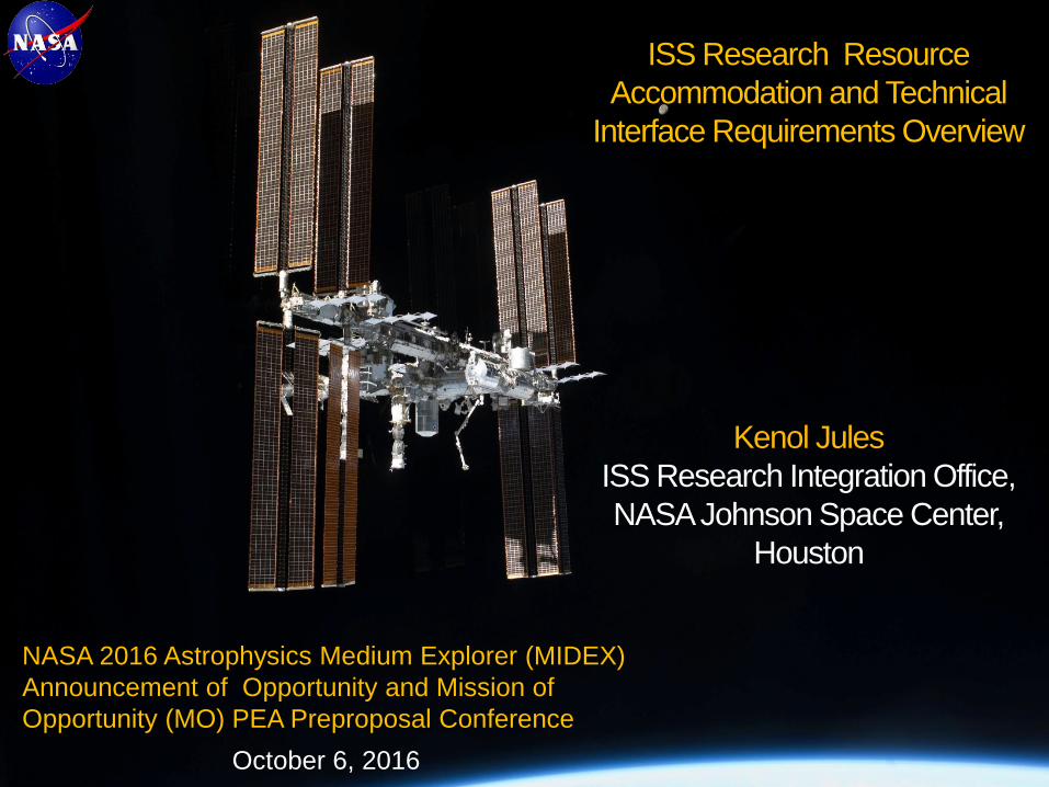
NASA 2016 Astrophysics Medium Explorer (MIDEX)
Announcement of Opportunity and Mission of
Opportunity (MO) PEA Preproposal Conference
October 6, 2016
ISS Research Resource
Accommodation and Technical
Interface Requirements Overview
Kenol Jules
ISS Research Integration Office,
NASA Johnson Space Center,
Houston
1
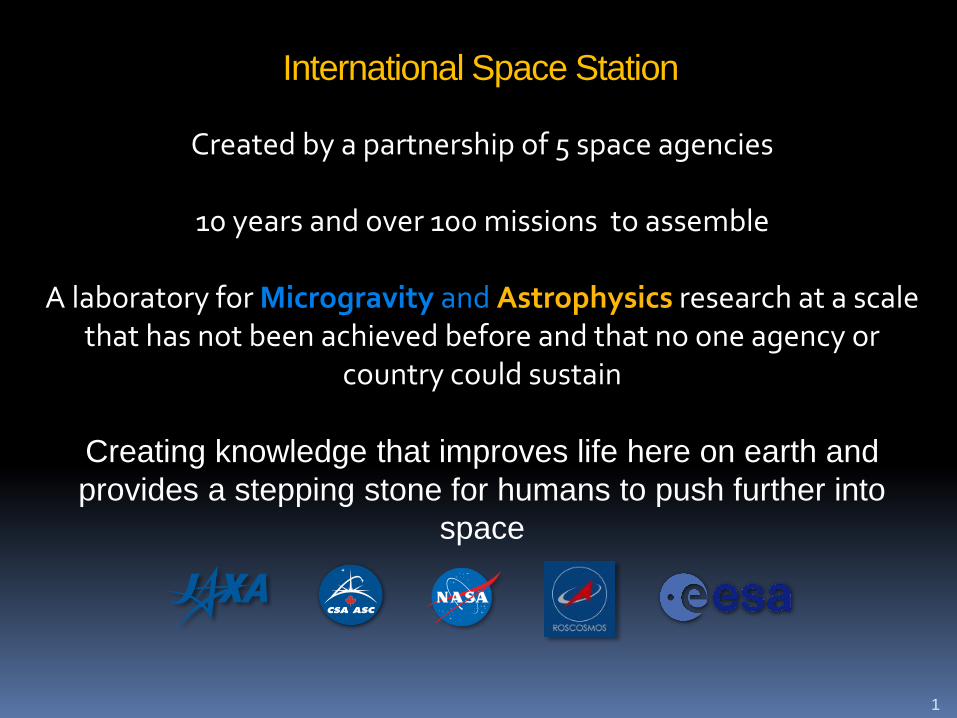
International Space Station
Created by a partnership of 5 space agencies
10 years and over 100 missions to assemble
A laboratory for Microgravity and Astrophysics research at a scale that has not been achieved before and that no one agency or
country could sustain
Creating knowledge that improves life here on earth and
provides a stepping stone for humans to push further into
space

2
A collaboration of 5 space agencies

Global Ground-Based Infrastructure
4

Research Sponsors on ISS
Commercial Sector
Non-profit organizations
U.S. Government Agencies
International
Partner
Research
NASA ResearchHuman Exploration
Science Mission
Space Technology
Russian
Research
Biology and Biotechnology, Earth, Space Science, Educational Activities,
Human Research, Physical & Material Sciences andTechnology Demonstration
CASIS - National Lab
5
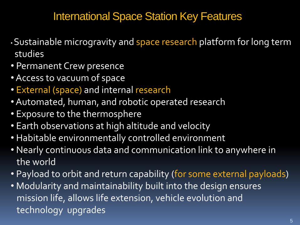
International Space Station Key Features
• Sustainable microgravity and space research platform for long termstudies
• Permanent Crew presence• Access to vacuum of space• External (space) and internal research• Automated, human, and robotic operated research• Exposure to the thermosphere• Earth observations at high altitude and velocity• Habitable environmentally controlled environment • Nearly continuous data and communication link to anywhere in
the world• Payload to orbit and return capability (for some external payloads)• Modularity and maintainability built into the design ensures
mission life, allows life extension, vehicle evolution and technology upgrades
6
ISS Payload Philosophy
Our goal is to fly and operate a payload as soon as it is
ready
To operate the ISS like a laboratory to enable the flexibility
for investigators to adapt their research plan based on new
and unexpected findings
To continue to make the integration and operation of
payloads on ISS as simple and ground lab like as possible

External Payload
Attach Sites

RRM (On Orbit)MUSES (SpX-11/2017)SAGE III (SpX-10/2016)
OCO-3 (SpX-17/2018)CATS (On Orbit)CREAM (SpX-12/2017)GEDI (Spx-18/2018)ECOSTRESS (SpX-15/2018)MAXI (On- Orbit)CALET (On Orbit)NREP (On Orbit)MCE (On Orbit)SEDA AP (On Orbit)EFU Adapter 1 (On Orbit)
RapidSCAT (On Orbit)HDEV (On Orbit)ASIM (SpX-13/2017)ACES (SpX-13/2017)SDS (SpX-13/2017)GEROS (SpX-20/2019)SOLAR (On Orbit)
STP-H4 (On Orbit)OPALS (On Orbit)LIS on STP-H5 (SpX-10/2016)ROSA (SpX-11/2017)RRM3 (SpX-14/2018)RRM3 (SpX-15/2018)
Nicer (SpX-11/2017)MISSE-FF (SpX-14/2018)
Current and Future External Payloads
SCANTestbed (On Orbit)TSIS (SpX-14/2018)STP-H6 (SpX-17/2018)

The Japan Aerospace Exploration Agency (JAXA) has demonstrated small satellite
deployment from the Japanese Experiment Module "Kibo" of the International
Space Station (ISS) in order to enhance the capability of Kibo's utilization and to
offer more launch opportunities to small satellites.
External Sites
10
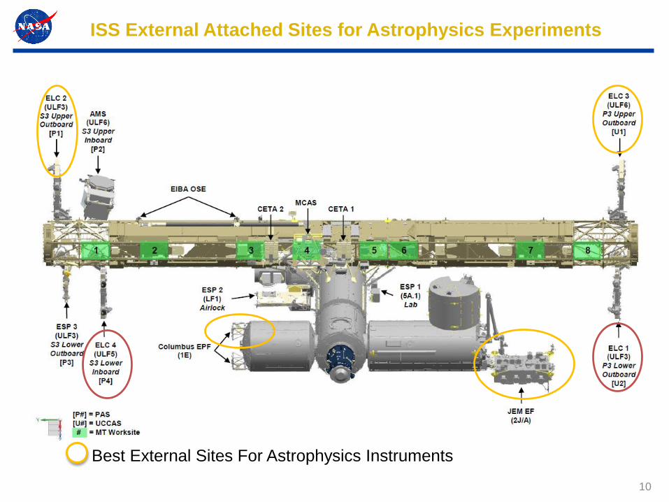
ISS External Attached Sites for Astrophysics Experiments
Best External Sites For Astrophysics Instruments

11
ELC-2 (Both Ram)
Starboard upper
2 Zenith payload sites
CMG
PFRAM
Pump
Module
NTATUS-RA
P/L
PFRAM
P/L
PFRAM
HPGT
FSE
Outboard Side Inboard Side
CTC-3
ELC-3 (3-Ram;5-Wake)
Port upper
2 Zenith payload sites
Express Logistics Carriers Overview
Payload Locations Circled
Site 3Site 7
Site 3Site 5

12
Express Pallet Adapter (ExPA) Assembly (GFE)
Payload structural interface
Active heating, passive coolingPayload thermal interface
Power(120VDC & 28VDC): Four NATC
connectors
Data (1553, Ethernet): Six NATC connectors
ExPA overall dimension
255 lbExPA overall Mass ELC Single Adapter
Resources
Payload electrical interface
46.05” x 47” x 13.06” (H)
Express Pallet Adapter
(ExPA) Assembly
FRAM
Adapter plate
2.756” X 2.756” Grid with 250-28 UNF Locking
Inserts and 1.625” diameter Shear Boss
Provisions
EVA handrail provisionsEVA compatibility
All EVR interfaces on ExPAEVR compatibility
ExPA payload carrying capability 34” x 46” x 49” (H) and 500 lb”

13
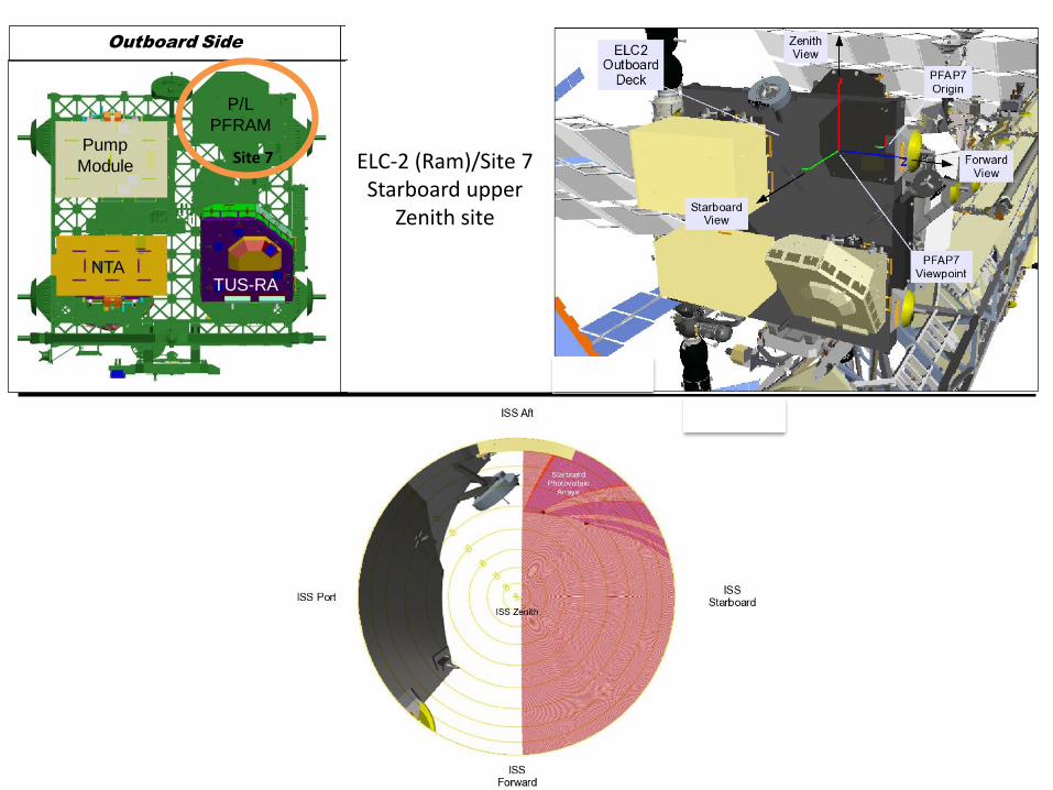
Placement of “Eye” Point for Sensor Viewing for Field of View
Analysis
CMG
PFRAM
Pump
Module
NTATUS-RA
P/L
PFRAM
P/L
PFRAM
HPGT
FSE
Outboard Side Inboard Side
CTC-3
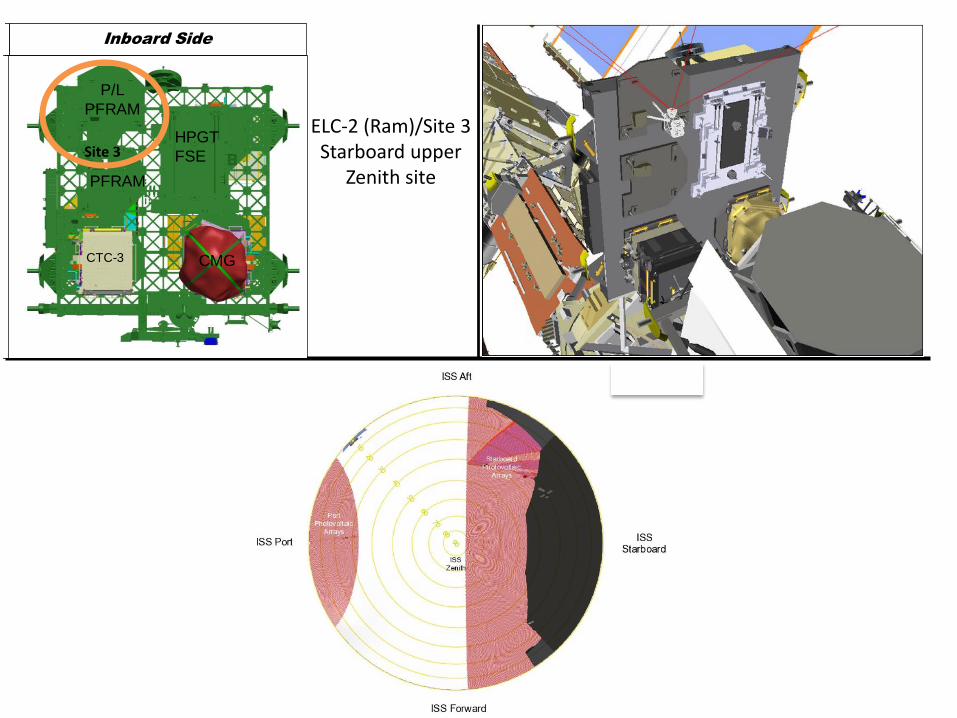
Site 3
ELC-2 (Ram)/Site 3Starboard upper
Zenith site
CMG
PFRAM
Pump
Module
NTATUS-RA
P/L
PFRAM
P/L
PFRAM
HPGT
FSE
Outboard Side Inboard Side
CTC-3
Site 7 ELC-2 (Ram)/Site 7Starboard upper
Zenith site
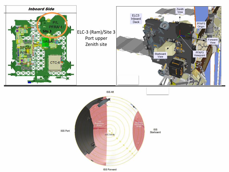
Site 3 ELC-3 (Ram)/Site 3Port upperZenith site

Site 5 ELC-3 (Wake)/Site 5Port upperZenith site

18
Columbus External Resources
Mass capacity 230 kg (500 lb)
Volume 1 m3
Power2.5 kW total to carrier
(shared)
Thermal Passive
Low-rate data 1 Mbps (MIL-STD-1553)
Medium-rate data 2 Mbps (shared)
Sites available to NASA 2 sites
Columbus External Research Accommodations

19
Columbus EF Overview
Location Viewing
Payload
Size Power Data
SOZ Zenith
226 kg +
CEPA
1.25 kW at
120 VDC
2.5 kW
max
(Shared)
Ethernet,
1553
SOX Ram
SDX Ram
SDN Nadir

20
Columbus External Payload Envelope Dimensions
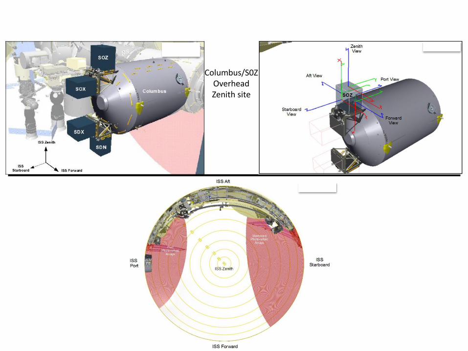
Columbus/S0ZOverheadZenith site

Columbus/SOXOverheadZenith site

23
Mass capacity
550 kg (1,150 lb) at standard site
2,250 kg (5,550 lb) at large site
Volume 1.5 m3
Power 3-6 kW, 113 – 126 VDC (Shared resource)
Thermal 3-6 kW cooling (Shared resource)
Low-rate data
Medium-rate data
1 Mbps (MIL-STD-1553, two way)
1EEE-802.3(10BASE-T, two way) *
High-rate data 43 Mbps (shared, one way downlink)
Sites available to NASA 5 sites
JEM EF External Research Accommodations
NASA/DOD
HREP payload
X
Y
WX
Z
H
LL
Grapple Fixture (GFE)
PIU
(GFE)Top ViewSide View
PIU
(GFE)
Axis mm ft inch
W 800 2 7.50
H 1000 3 3.37
L 1850 6 0.83 • Ethernet bus is tested to 100BASE-T capacity.
• Upgrade to 100BASE-T is being worked by JAXA

24
JEM-EF
JEM EF EFU Location Overview
2 64 8
1 3
11
5 7
Dedicated to ICS
10EPMP Berthing location
9Only location with Port view
12
Temporary Parking
Pressurized Module
FOV obstruction
Slight obstruction from camera mount;
obstructed during EP berthing
Good zenith viewing
*6 kW;
Ethernet,
1553, Video
6 kW;
Ethernet,
1553, Video
*
* Capability for 2.5 MT payload
3 kW;
Ethernet,
1553, Video
3 kW;
1553, Video
3 kW;
1553, Video
3 kW;
Ethernet,
1553, Video
3 kW;
1553, Video
3 kW;
Ethernet,
1553, Video
3 kW;
Ethernet
3 kW;
Ethernet
FOV obstruction
Both power and active cooling are shared resource for all operating payloads during an increment

25
ISSP Management JEM-EF Power & Flow Design Limit Directive
• Due to the JEM-EF system constraint to meet the external payload
complement needs for power and fluid flow rate during the 2018-2022
timeframe to allow all of them to operate continuously at the same time,
ISSP is directing PDs to design their instruments to perform within the
limitation of the JEM-EF system capability in order to minimize payloads real
time operation timelining
• *JEM-EF system can support the following during the 2018-2022 timeframe:
– Maximum fluid flow per payload: 151 kg/hr
– Maximum Power draw per payload: 500 W
– Maximum accumulator volume: 2L
* Deviation from these values above will significantly increase the likelihood of
that payload complement to be timeline during real time operation of that
increment, which means less continuous on-orbit operation of all the payloads
in that increment at the same time

26
JEM-EF Detailed Accommodations by Site
Location Viewing
Payload
Size Description / Notes Data
1 Ram, Nadir, Zenith 500 kg Ram field of View (FOV) obstruction by JEM module Ethernet, 1553, Video
3 Ram, Nadir, Zenith 500 kg Clear view Ethernet, 1553, Video
5 Ram, Nadir, Zenith 500 kg ICS System back-up site (negotiable?) 1553, Video
7 Ram, Nadir, Zenith 500 kg ICS-dedicated -
9 Port, Zenith, Nadir 2.5 MT Best volumetrically for large payloads (up to 2.5 MT),
but not necessarily the best viewingEthernet, 1553, Video
2Wake, Nadir,
Zenith2.5 MT
Can hold large payloads, but has an FOV obstruction
by JEM moduleEthernet, 1553, Video
4Wake, Nadir,
Zenith500 kg Clear view 1553, Video
6Wake, Nadir,
Zenith500 kg Clear view Ethernet, 1553, Video
8Wake, Nadir,
Zenith
500 kg Obstruction during EP berthing, slight obstruction from
camera mount1553, Video
10Wake, Nadir,
Zenith500 kg EPMP berthing site -
11 Zenith only 500 kg Good Zenith viewing Ethernet
12 Zenith only 500 kg Temporary stowage location Ethernet

27
JEM-EF External Sites Locations
EFU10
EFU11

28
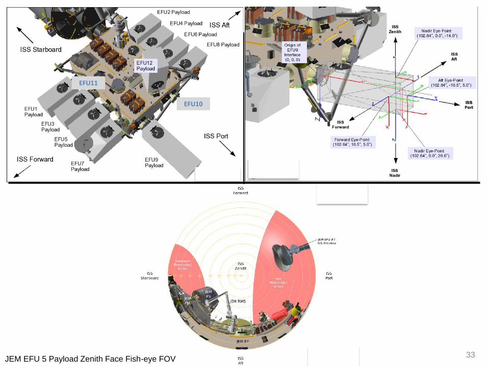
Placement of Eye-Point for Sensors Located on a Generic EFU Payload Box

29
EFU11
JEM EFU 1 Payload Zenith Face Fish-eye FOV
EFU10

30
EFU11
JEM EFU 2 Payload Zenith Face Fish-eye FOV
EFU10

31
EFU11
JEM EFU 3 Payload Zenith Face Fish-eye FOV
EFU10

32
EFU11
JEM EFU 4 Payload Zenith Face Fish-eye FOV
EFU10
33
EFU11
JEM EFU 5 Payload Zenith Face Fish-eye FOV
EFU10

34
EFU11
JEM EFU 6 Payload Zenith Face Fish-eye FOV
EFU10

35
EFU11
JEM EFU 8 Payload Zenith Face Fish-eye FOV
EFU10

36
EFU11
JEM EFU 9 Payload Zenith Face Fish-eye FOV
EFU10
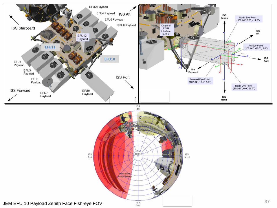
37
EFU11
JEM EFU 10 Payload Zenith Face Fish-eye FOV
EFU10

38
EFU11
JEM EFU 11 Payload Zenith Face Fish-eye FOV
EFU10

39
EFU11
JEM EFU 12 Payload Zenith Face Fish-eye FOV
EFU10

40
Payload Allowable Up-Mass & Volume Summary Table
Payload Volume
(W x H x L) Total Weight
Accommodation
Weight (including
adapter plate)
Allowable Payload
Weight (including
Flight Support
Equipment)
Attach Payload
Location
31.5” x 39.4” x 72.8”
(800mm x 1000mm x
1850 mm)
1100 Lb
(500 Kg)
121 Lb
(55 Kg)
979 Lb
(445 Kg)JEM-EF
34” x 49” X 46”
(863mm x 1244mm x
1168 mm)
638 Lb
(290 Kg)
250 Lb
(114 Kg)
388 Lb
(176Kg)Columbus (CEPA)
34” x 49” X 46”
(863mm x 1244mm x
1168 mm)
740 Lb
(336 Kg)
250 Lb
(114 Kg)
490 Lb
(222 Kg)
ELC (ExPA)
*See ExPA & CEPA
payload specification
for ELC & CEF
*See ExPA & CEPA
payload specification
for ELC & CEF
See ExPA & CEPA
payload specification
for ELC & CEF
See ExPA & CEPA
payload specification
for ELC & CEF
HTV Exposed
Pallet (ExPA,
CEPA Payload)
31.5” x 39.4” x 72.8”
(800mm x 1000mm x
1850 mm)
1100 Lb
(500 Kg)
121 Lb
(55 Kg)
979 Lb
(445 Kg)
HTV Exposed
Pallet (JEM EF
Payload)
* Location constraint applies in HTV Exposed Pallet

41
Dexterous End Effector
SSRMS attachment which the ground team or on-orbit crew can
use robotically to install, remove and replace payloads and failed components

42
Robotic Installation of Instrument to ISS
43
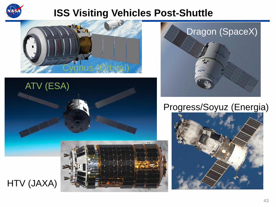
ISS Visiting Vehicles Post-Shuttle
Cygnus (Orbital)
Dragon (SpaceX)
Progress/Soyuz (Energia)
ATV (ESA)
HTV (JAXA)
44
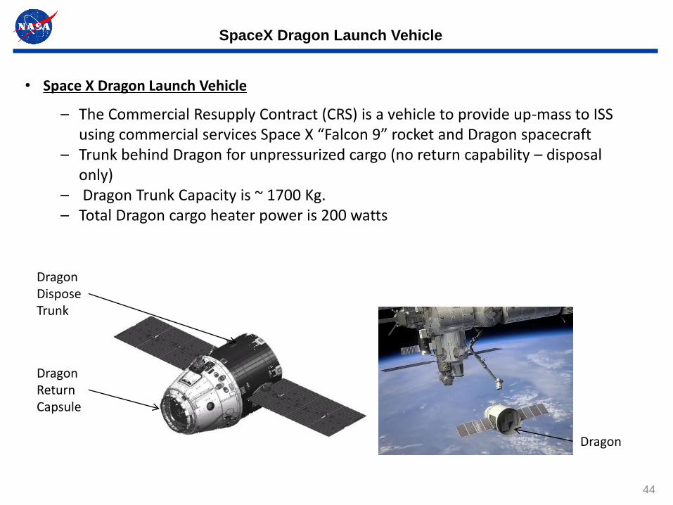
SpaceX Dragon Launch Vehicle
• Space X Dragon Launch Vehicle
– The Commercial Resupply Contract (CRS) is a vehicle to provide up-mass to ISS using commercial services Space X “Falcon 9” rocket and Dragon spacecraft
– Trunk behind Dragon for unpressurized cargo (no return capability – disposal only)
– Dragon Trunk Capacity is ~ 1700 Kg.– Total Dragon cargo heater power is 200 watts
Dragon
Dragon Return Capsule
Dragon Dispose Trunk

SpaceX Dragon External Payload Trunk FRAM Lay-out

SpaceX Dragon External Payload Trunk JEM-EF Lay-out
47
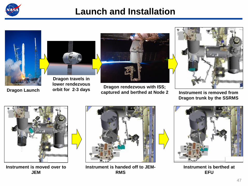
Launch and Installation
Dragon Launch
Dragon travels in
lower rendezvous
orbit for 2-3 daysDragon rendezvous with ISS;
captured and berthed at Node 2 Instrument is removed from
Dragon trunk by the SSRMS
Instrument is moved over to
JEM
Instrument is berthed at
EFU
Instrument is handed off to JEM-
RMS

48
ISS Feasibility Accommodation Assessment Evaluation Criteria
• In performing the accommodation feasibility assessments, the ISS
Integration Research office (RIO/OZ) looks at whether or not the
proposed instrument meets the standard interfaces or requires
significant non-standard integration re/work
• For example, the volumes are defined for each platform but there are
specific dimensions that make up those volumes
• Working with the proposer, we will evaluate the dimensions and
determine if the instrument is within the standard dimensions or exceeds
those dimensions in one or more areas
• If it exceeds the standard interfaces, we will provide an evaluation of how
simple or hard it will be to accommodate those non-standard interfaces
• The proposers will be made aware of any non-standard interfaces to
determine if they can modify their design to stay within the standard
interfaces
• A lot of times, non-standard interfaces CAN be accommodated but it
requires additional work during the integration process

49
ISS Accommodation Feasibility Assessments
Nominal Data Required From Proposer Team
• Payload Upmass (Includes both instrument and ISS Interface
Hardware
• Volumetric Dimensions (both static and dynamic)
• Power consumption (includes peak power)
• Data rates (includes any data latency requirements)
• Pointing/viewing needs
• Lifetime required on orbit
• Instrument readiness date (date payload is ready to fly to ISS)
• Return plan
50
Astrophysics Explorers ISS Feasibility Assessment Process
1. Contact the Space Station Research Integration Office (RIO/OZ) at the NASA
Johnson Space Center to start a dialogue and arrange for a feasibility
assessment telecon:
• Kenol Jules ([email protected], 281-244-5516)
2. Provide background information on the AO that your team is responding to, HQ
Program Scientist (PS) and Program Executive (PE) names and your
instrument technical information, such as:
• Description of instrument concept and preliminary design approach
• Estimate of launch/on-orbit mass, on-orbit volume/dimensions, power,
data downlink requirements, need for cooling, and your preliminary
assessment of possible ISS site locations for your proposed instrument
• Any mass or volume/dimensions that exceed ISS standard operational
instrument envelopes for a particular site will require a waiver---small
deviations can often be accommodated
• RIO will assess your overall design approach and let you know the
suitability of your proposed design concept for accommodation on ISS. If
your design concept has envelope exceedances, we will let you know
possible options related to them.

51
3. To complete the assessment several follow-up telecons may be
needed, email exchanges and additional data requests are to be
expected
4. Once the ISS assessment team has reviewed all potential ISS
accommodations and interfaces issues and had had discussions about
them with the proposer team, a draft preliminary ISS accommodation
feasibility letter will be generated by RIO
5. The draft feasibility letter will be reviewed with the proposer team for
any comment. The content of the letter focuses on the issues identify
by the assessment team, which were discussed with the proposer team
and it is solely based on the information provided by the proposer at
that time
6. The feasibility letter is signed by the RIO manager and issued to the
proposer team
7. The whole process can take 6 to 10 weeks, depending on the
complexity and maturity of the design concept from the proposer team
Science Mission Explorer ISS Feasibility Assessment Process

52
8. Once the proposals are submitted to NASA, the ISS specific proposals
will be reviewed again (in depth this time around) by the ISS RIO in
order to issue a final ISS accommodation feasibility letter to the PS,
using information provided in the proposals
9. When a proposal is selected for funding, SMD will initiate contact with
RIO, which in turn will initiate contact with the proposer team or vice
versa to start discussion leading to the instrument integration process
to be flown to ISS
10. An authorization to proceed (ATP) will be provided to the ISS office by
SMD to official assigned that instrument on ISS at a specific site,
launch vehicle with readiness to fly date
11. An ISS integration team will be activated to support the integration
process of that instrument on ISS
12. Once the proposer/PI/PD team is under contract with SMD, an ISS
kick-off meeting will be held at the Johnson Space Center to start the
ISS integration process
Science Mission Explorer ISS Feasibility Assessment Process

Questions?
Contact Information:
Kenol Jules
NASA Johnson Space Center
Email: [email protected]
Tel.: 281-244-5516

54
ISS External Sites Availability Forecast till 2024