Embed Size (px)
Citation preview

Kerf Bent Clock Front Toolpaths in MasterCAM
Open the MasterCAM application and open your clock front geometry file.

For 2D geometry such as we have, there are 2 main types of tool paths. The first one is a
contour. In a contour toolpath the tool bit will follow a path. The path can be one piece of
geometry or multiple pieces of geometry linked together end to end (this is called a chain).
When the geometry is selected you must either pick the single option or the chaining option
(multiple objects laid out end to end) before you select the geometry. We are going to
complete three contour toolpaths on the three singular pieces of geometry. The second type of
toolpath is a pocket. A pocket toolpath will make a cavity inside the selected geometry. For the
clock front, we do not need a pocket toolpath, but you will use them when we get to the box.
To start the toolpaths, go to Toolpaths/contour
When the new NC dialog box
comes up, type in a good file
name such as Clock Front.
Click the green check.
The Chaining dialog box should appear.
MasterCAM prompts you to select the
geometry you want to associate with
the toolpath. Instead of chaining, the
circle is only one object, so click on the
single option.
Then click on the inside circle to select
it.
Once the inside circle is selected (it should
turn white/dashed and have a green arrow
on the right side of it) click on the green
check box (ok) to finish the selection.

In the 2D Toolpaths – Contour dialog box, please enter the following information:
Right- click in
this white space


You should now see the ½
flat endmill or straight bit
in this window. This is the
bit we will use to cut the
piece.
Enter 100 for feed rate
And 30 for plunge rate


Basically, we just set up the parameters for the
contour cut. We still need to set the depth of the
cut. But, the only Cut Parameters that should be
turned on are the depth cuts (set at .125). It
should look like the picture on the left.

To set the depth of the cut, please enter the below values. In the Linking Parameters tab. Notice that all
the values are “Absolute” and the depth is a -.75.
Now we can finally hit the OK check to enter all these values and
MasterCAM will draw the contour toolpath on the circle.

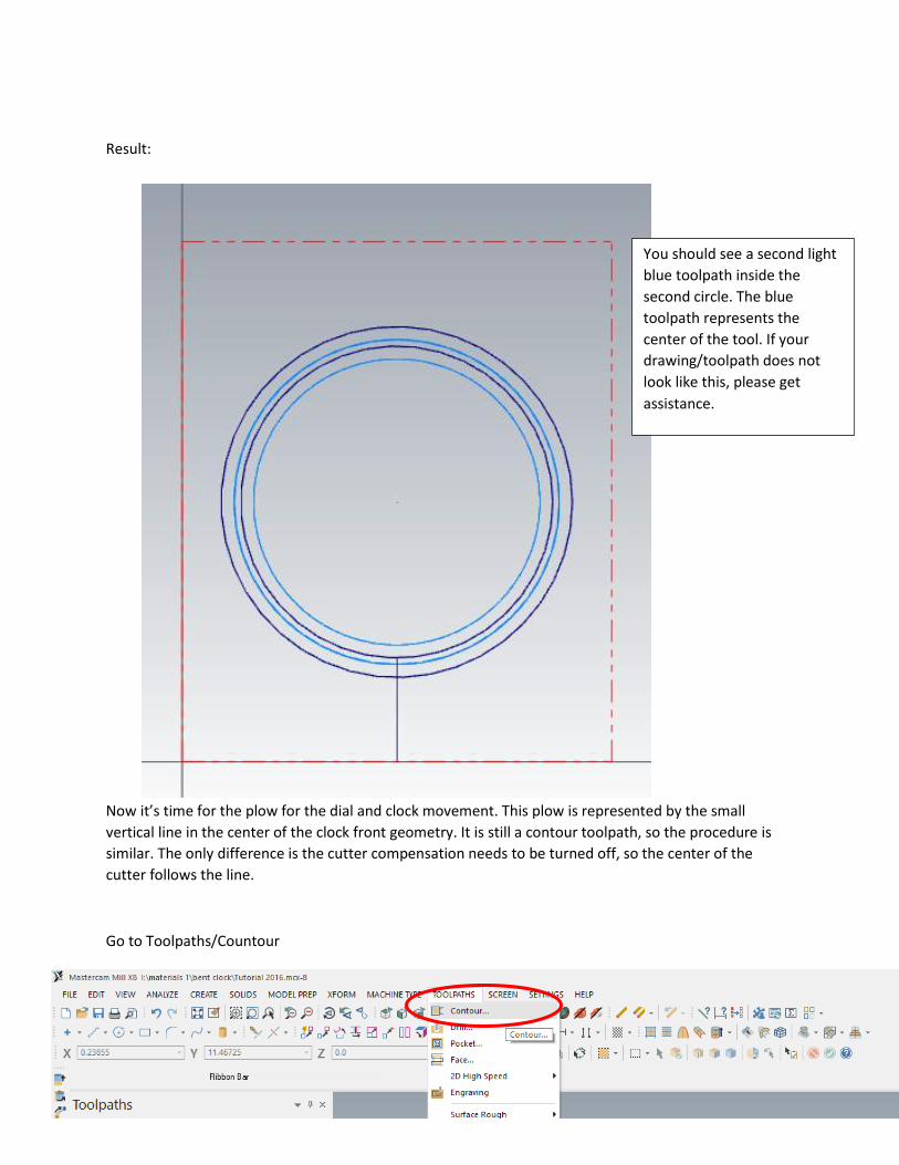
Result:
The second toolpath is similar to the first. It will be a contour with the same cut parameters and same
tool, but we will not go all the way through the piece. This time we will make a rabbit, so the depth will
be -3/8” or -.375.
You should see a light blue
toolpath inside the inside
circle. The blue toolpath
represents the center of the
tool. If your drawing/toolpath
does not look like this, please
get assistance.

Go to toolpaths/contour.
Again, go to single, and click on the outside circle this time.
Once the outside circle is selected (it should turn white and
have a green arrow on the right side of it) click on the green
check box (ok) to finish the selection.
Click on the outside circle
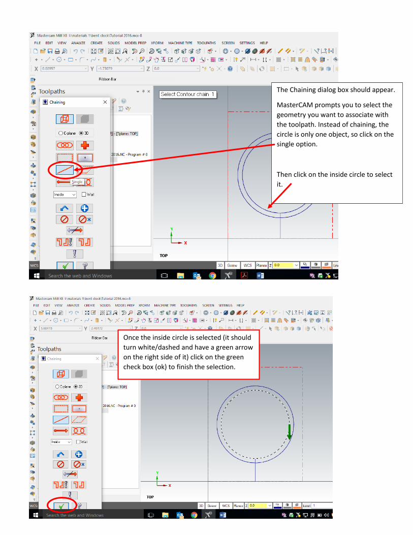
After you hit the OK button for selecting geometry for the toolpath, the 2D contour toolpath window
pops up. This should have all the same settings we set for the first toolpath except for the depth. So you
can check all the cut parameters and see if they are the same (they should be, if not just enter the same
information for the last contour). Once you check the cut parameters, go to linking parameters and
enter the depth of -.375.
Then hit OK.
Result:
Now it’s time for the plow for the dial and clock movement. This plow is represented by the small
vertical line in the center of the clock front geometry. It is still a contour toolpath, so the procedure is
similar. The only difference is the cutter compensation needs to be turned off, so the center of the
cutter follows the line.
Go to Toolpaths/Countour
You should see a second light
blue toolpath inside the
second circle. The blue
toolpath represents the
center of the tool. If your
drawing/toolpath does not
look like this, please get
assistance.

This contour tool path properties are similar to the other ones, but we need a couple of changes. So
follow along and enter the following information into all the windows.
Click on the single option.
Then click on the top portion of the
vertical line.
Then hit OK

The same tool we used last
time should be active. This is
correct.
In cut parameters, change the
compensation type to OFF.
This will put the center of the
cutter on the line.

All the other cut parameters should be
off (they should have the little red
next to them).

This should draw the toolpath, you probably will not see the toolpath since the center of the cutter
follows the line. So you probably just see the line unless you are in a different view.
Result:
Most of the values should be
the same as before, please
check. Then enter the depth of
-.375 and hit the green check.
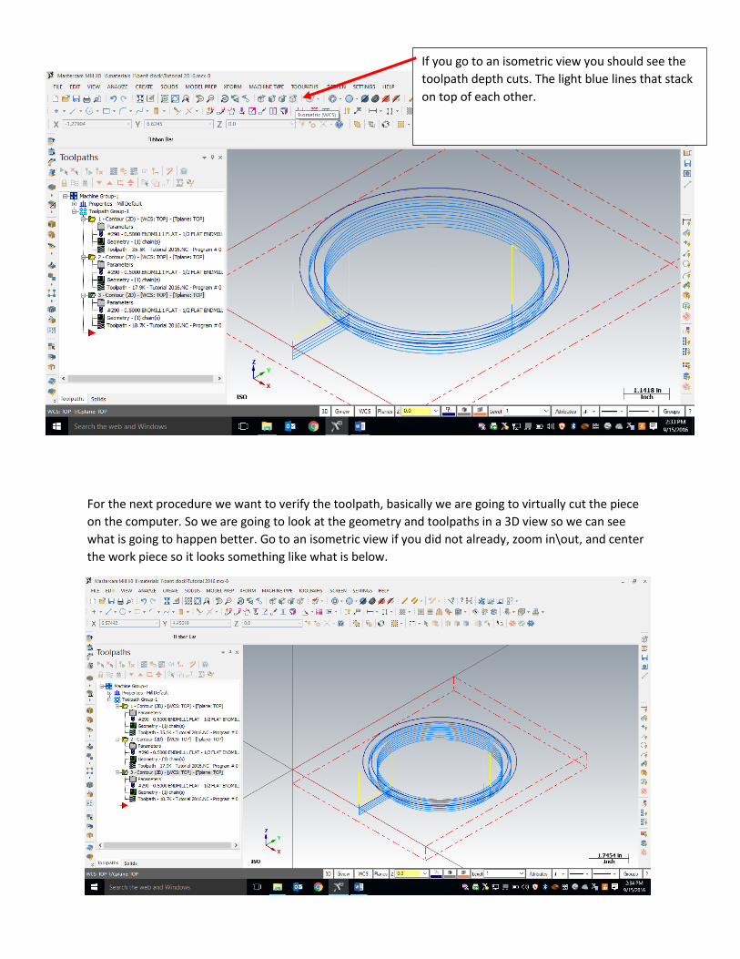
For the next procedure we want to verify the toolpath, basically we are going to virtually cut the piece
on the computer. So we are going to look at the geometry and toolpaths in a 3D view so we can see
what is going to happen better. Go to an isometric view if you did not already, zoom in\out, and center
the work piece so it looks something like what is below.
If you go to an isometric view you should see the
toolpath depth cuts. The light blue lines that stack
on top of each other.

To verify the toolpaths, do the following:
The MasterCAM Toolpath Simulator should open up in a new window. Like below.
1st click this green arrow to select all the toolpaths.
Then click this the Verify button. It’s like a folder
with a green check.

To verify, click the play button at the bottom of the MasterCAM Simulator, and your work piece should
look like below. Please show your instructor to receive credit.
Congratulations, you drew all the toolpaths you need for the clock front. Please show Mr.
Marmor so he can sign off on your completion of the process..