Embed Size (px)
Citation preview

Key Solutions for a Massive MIMO FDDSystem
Wolfgang ZirwasNokia Bell Labs
Munich, GermanyEmail: [email protected]
Mikael Sternad, Rikke ApelfrojdSignals and Systems
University of Uppsala, Uppsala, SwedenEmail: [email protected]
Abstract—The ongoing standardization within 3GPPfor the so called new radio (NR) system has identifiedmassive multiple-input multiple output (MIMO) transmis-sion, also called full dimension MIMO, as one of themain contributors to higher spectral efficiency for themobile broadband case. In particular for radio frequenciesbelow 6 GHz, channel estimation has to be supported infrequency division duplex (FDD) as well as time divisionduplex (TDD) operation. In TDD we may obtain downlinkchannels by estimating uplink channels, assuming reci-procity. For FDD, codebook based design as well as sometype of explicit feedback is under discussion. Separately,there are also ongoing discussions of the question ifmassive MIMO in combination with FDD is a reasonablechoice at all.
Here we highlight some of our recent results obtainedwithin several 5G research projects. To our understandingthey overcome some of the inherent limitations of massiveMIMO for FDD. As indicated by simulations, the resultingconcept enables a grid of beam (GoB) and referencesignal design with a reasonable downlink reference signaloverhead of around 10 percent, together with reasonablefeedback overhead of several hundred kbit/s per UE. Sucha design attains around 90 percent of the massive MIMOsystem performance with ideal channel state information.
Keywords — massive MIMO; channel estimation;CoMP; pilot contamination; beam management
I. INTRODUCTION
There is an ongoing debate about the possibleand preferable ways to exploit the benefits of mas-sive multiple-input-mupltiple output (MIMO) antennaarrays. The original downlink concept is based on theusage of time division duplex (TDD) and the assump-tion of channel reciprocity, while a frequency divisionduplex (FDD), grid of beam concept has been proposedin, e.g., [1].
Recently, an interesting and thought-provoking inputto this debate has been provided by a paper presentlystill under review [2]. It evaluates the use of variousFDD-based massive MIMO schemes by using measuredchannels from a test-bed in Lund, Sweden. It concludesthat FDD massive MIMO grid of beam (GoB) systemsare not robust with respect to the investigated scenariosand often perform far from the theoretical performance
bound. This paper, in line with several other researchgroups, see e.g. [3], regard the use of TDD as the onlyfeasible solution.
However, on closer inspection, the massive MIMOsetting creates not only challenges, but also propertiesof the channels that can be used to overcome thesechallenges. In particular, a typical radio channel canbe made sparse in the spatial domain. This allows toconsider new solutions that overcome some of the mainconcerns regarding the use of massive MIMO in FDD.It also enables the cooperation of a still larger numberof antenna elements at multiple sites, a combinationof massive MIMO and coherent coordinated multipointtransmission (JT-CoMP), or network MIMO [1].
We begin this paper in Section II by briefly reca-pitulating the main concerns with respect to FDD, asexpressed for example in [2], and complement withsimilar observations from our measurements and systemlevel simulations. In particular, non line of sight (NLOS)urban macro scenarios are characterized by multiplereflections. Therefore, under the assumption of a gridof beam (GoB) design, downlink users (UEs) receivenot only one strong beam, but instead many so calledrelevant channel components that are above a powerthreshold. These relevant channel components vary incase of MU MIMO for different UE locations and wouldhave to be estimated as well as reported individually forall scheduled UEs, with sufficiently high quality. Thiscreates both a reference signal overhead problem sincemany channels have to be estimated simultaneously, andalso an uplink feedback overhead problem.
We then in Section III present tools and ideas forovercoming the most severe issues, with a main focuson the required overhead due to downlink referencesignals for obtaining the channel state information (CSIRS). We introduce our concept of coded CSI RS , whichacts as a game changer: Using this design, the referencesignal overhead just scales with the typical number ofrelevant channel components to be estimated per UE,instead of with the total number of antenna elementsor beams. In particular, the overhead does not scale ap-proximately linearly with the number of simultaneouslyserved UEs as is the case in, e.g., [3]. A reference signaloverhead that scales with the number of UEs would alsobe a problem for several recently suggested schemes for978-1-5386-3531-5/17/$31.00 c© 2017 European Union
the reduction of the downlink reference signal overheadin FDD massive MIMO, see e.g. [4], [5], [6] and [7].
A massive network MIMO GoB framework, devel-oped recently within the EU H2020 Fantastic5G project,[1], will be presented and utilized. We will extend thisframework in Section IV by providing a novel beamdeactivation scheme. It simultaneously improves theCSI estimation quality and reduces the CSI reportingoverhead. A simulation that includes appropriate usergrouping, scheduling, CSI estimation, reporting of rele-vant channel components and taps as well as the beamdeactivation, is then presented in Section V. It indicatesa high potential for massive MIMO FDD systems. Dueto page limits, we refer to suitable references for manydetails of the involved components of the solution.
II. CHALLENGES FOR A MASSIVE MIMO FDDSYSTEM
There are good reasons that the original conceptsfor massive MIMO as well as for JT CoMP havebeen developed for TDD systems. Assuming a highnumber of downlink transmit antennas, either at a singleor at a distributed antenna array, typically requiresa high number of orthogonal CSI RSs in FDD. Itwould also require a high uplink overhead for reportingthe estimated CSI from the UEs to the base station(denoted next generation NodeB, or gNB, in evolving5G standards). In contrast, the use of ideally just a singleuplink sounding reference signal (SRS) per UE and perradio resource block would allow the estimation of alluplink radio channels to all antenna elements. In TDDsystems, these might then be reused for the downlinkdue to the reciprocity of downlink and uplink radiochannels.
In FDD, channel reciprocity cannot be assumed.Downlink channel estimation by the use of orthogonaldownlink CSI RSs, one per antenna element, hereencounters a fundamental limitation: The channel co-herence time and the coherence bandwidth will set anupper bound for the number of orthogonal CSI RSs.In addition, there will be an optimum balance of CSIRS overhead versus user data transmission within sucha (block fading) transmission block. This tradeoff isbetween reporting of more relevant channel componentswith higher accuracy versus reducing the number ofresource elements available for data transmission, thuslimiting the maximum data throughput.
A first countermeasure to this problem is to use atransformation from the sets of antennas into a beamspace at the gNB, the so called GoB concept. Thenumber of beams may be equal to, larger or smallerthan the number of antennas. If we chose to use equal orfewer beams than number of antennas, then the numberof channel components that are strong for a user, andtherefore need to be estimated, is reduced, due to thedirected transmission of beams.
The balance here is that the use of too few beamswill reduce the attainable performance and the multiuser
MIMO scheduling gain. We will in the following as-sume that the number of beams is so high that each usertypically receives strong signals from several beams, de-noted relevant beams, or relevant channel components.
High cell capacity requires spatial multiplexing ofmultiple streams to multiple UEs. Each UE k ∈ NK
will receive Nrel,k beams above a specified powerthreshold. The number NRS of required orthogonal CSIRSs will then scale with max(Nrel,k) and with K. Inthe from an overhead perspective best - but unlikely- case, all UEs would have the same Nrel beams asrelevant channel components.1 In the opposite extremecase, each UE would have a different set of relevantbeams so that NRS =
∑k
Nrel,k orthogonal reference
signals would be required. A typical situation will besomewhere in between. Even with a GoB, the use ofa minimal number NRS of orthogonal CSI RSs wouldtherefore still require a large overhead. It would alsorequire adaptation of the transmitted CSI RSs to the setof currently scheduled UEs.
The results in [2] are based on measured radio chan-nels. Block wise fading and allocation of the best fittingset of orthogonal CSI RS for various FDD scenariosis assumed. Due to the CSI RS overhead, in somecases only 40% to 50% of the capacity with perfectCSI is then attained. This, obviously, would be a strongdrawback for a FDD system.
Generally, these observations are in line with ourown evaluations. For example in the study [8] of theGoB concept, Nrel,k varied from few to several tensof relevant channel components per UE. In addition therelevant channel components were different from UE toUE, depending on the user location.
A related problem is the CSI reporting overhead.For 3GPP LTE and new radio full dimension MIMO, thefocus is on codebook based feedback schemes for FDD.For a future phase II of the 3GPP New Radio standard-ization, also explicit CSI feedback is being considered,as it would result in improved precoder performancewith reduced inter-stream interference. However, therelated CSI feedback overhead has to be consideredcarefully. For example, reporting explicit CSI for 40channel components every 5 ms with a quantization of10 bit for each subband of 6 physical resource blocks(PRB) of a 20 MHz = 100 PRB system would result ina feedback rate greater than 1 Mbit/s for each UE.
An additional challenge has been identified in [2]:For clusters of closely spaced UEs, or a hot spot sce-nario, the performance with the GoB concept is reduced.This problem is caused by using a fixed allocation of alow to moderate number of beams that are designed tospan the full cell area. The number of beams serving ahot spot area might then become small and inadequate.
1However, as noted in the discussion on power normalization lossbelow, such a case would be the worst with respect to the possibilityto design a linear joint precoder with good properties.

To conclude, although a GoB system can alleviatethe downlink reference signal overhead problem in FDDby using a smaller number of beams than the numberof transmit antennas, there remain several challenges:The downlink reference signal overhead is still largewith orthogonal reference signals, the total feedbackload with many users will be large, and the number ofbeams covering a given area may be inadequate, whenusing a fixed positioning of beams.
III. HOW TO DESIGN A MASSIVE MIMO FDDSYSTEM
The introduction of an advanced interference miti-gation framework can become a main differentiator forNew Radio as compared to LTE. This motivates us toinvestigate our solution in a setting where JT CoMP isused over a cooperation area spanning several cells. Forexample, our evaluation case, described in Section Vbelow, consists of nine adjacent cells located at threesites, each equipped with a massive MIMO antennaarray, with in total Nbeam beams per cooperation area,where Nbeam = 288 will be used for evaluation.
Despite the high number of beams, our aim will beto achieve close to 90 percent of the ideal perfect-CSImassive network MIMO performance. The referencesignal overhead should be about 10 percent, togetherwith reasonable feedback overhead of about one toseveral 100 bit/subframe of 1 ms or, equivalently, a few100 kbit/s per UE. See for example the final deliverablefrom the EU project Fantastic5G [1].
a) Use of a Grid-of-Beams Downlink
A first step towards an efficient FDD solution isto exploit the spatial sparsity of a well designed GoBsystem. The number of relevant channel componentswill then be limited for each particular user, withNrel,k ≈ 10 to several tens of relevant channel com-ponents per UE, even in the case of a cooperation areawith, e.g., Nbeam = 288 potential beams. This is theresult of the directed transmission of the beams, ascompared to omni-directional single antenna elements.
To avoid problems with hotspots of users, the beampattern should be adaptable to the traffic demand ona slow time scale. Spatial clusters of UEs can then beserved by more beams than scheduled UEs.
b) Use of non-orthogonal coded downlink CSI RS
The next crucial step is to make the best use ofthe limited number of CSI RSs within the limitedcoherence time-frequency region. Here, the use of socalled coded CSI RSs [9], where non-orthogonal CSIRSs are allocated to antenna ports (AP) or beams, canbecome a game changer.
Briefly, instead of allocating one orthogonal CSI RSfor each of the Nbeam beams, so that NRS = Nbeam,each beam instead transmits a non orthogonal CSI RS
sequence of much shorter length. These non orthogonalsequences of length N coded
RS � Nbeam are unique perbeam. They should have the property to allow CSI re-construction at the UEs of almost all arbitrarily selectedsets of up to N coded
RS relevant channel components. EachUE will then be able to estimate its individual set of upto N coded
RS relevant channel components. For the overallCSI RS design, this means that the required overheadnow scales with the numbers Nrel,k of relevant channelcomponents. Details and evaluations of the concept ofcoded CSI RS can be found in [9] and in [10].
For example, assuming max(Nrel,k) = 40 relevantchannel components per UE, a sequence length of40 reference symbols is sufficient to allow all UEsto uniquely determine their UE-individual sets of rel-evant channel components. Ray tracing models andsystem level simulations have indicated that the numbermax(Nrel,k) = 40 is a reasonable assumption [9]. Therequired N coded
RS = 40 would then equal the number ofresource elements that is today used per PRB for CSIRSs in LTE systems. The corresponding overhead wouldthen be only 4.7 percent with one CSI RS transmissionevery 5 ms. This overhead might increase to around 10percent in case higher estimation accuracy or a higherCSI RS transmission rate is targeted.
Features that increase the spatial sparsity wouldhelp to further decrease the overhead and/or to improvethe estimation performance. For example, if UEs areequipped with eight receive antennas, then a suitablereceive beamformer can on average reduce the numberof relevant channel components by about 50% [8].
The important aspect here is that for spatially sparsechannels generated by massive MIMO GoB, we donot need orthogonal CSI RSs: Suitably designed non-orthogonal sequences of limited length are sufficient.
c) Use explicit CSI feedback for relevant channelsonly, and use feedback compression
To overcome the feedback challenge, we proposethe use of explicit CSI feedback per relevant channelcomponent, with compression that takes the statisticsof the time/frequency selective channel into account.
Reporting is then limited to channel componentsabove a pre-set power threshold. For a properly definedreporting threshold in the range of, e.g., 20 to 25 dBbelow the strongest channel component, the unreportedchannel components can be set to zero at the gNB whenforming the downlink beamformers. The inter-streaminterference due to the precoder mismatch will remainsmall.
As outlined in [11], we may let each UE report semi-statically, e.g., every 500 ms, the set of its relevantchannel components as well as the significant tapsof the channel impulse response. A relatively highoverhead will then be generated relatively rarely for theidentification of the relevant channel components andtaps. Then, normalized estimates of the significant taps
only are reported, with a rate adjusted to the fading andthe transmission requirements.
If the channel is sparse in the time domain, thenthe reporting of only the significant time-domain tapsof the channel, as suggested in [11], will be more ad-vantageous than source-coding the frequency-selectivefrequency-domain channels. In [12], the explicit feed-back is evaluated in a similar manner using compressedsensing, demonstrating its potential for sparse channelimpulse responses.
Again, the key to success is here to exploit sparsity,both spatially and temporally, and to design the overallsystem to have a sparse channel structure.
Analysis for measured urban macro radio channelsindicate that typically there are on average around 20relevant time domain taps per channel component. Evenwithout bit loading and assuming a ten bit quantizationper tap transmitted every 5 ms, around 40 kbit/swould then be required per channel component. For10 to 40 relevant channel components, a feedbackoverhead in the range of several hundred kbit/s perUE seems attainable. One should note that this casecovers frequency selective CSI information for the fullbandwidth of, e.g., 20 MHz. Lower subband sizes willgenerate lower overhead per UE.
The high-level downlink transmission concept
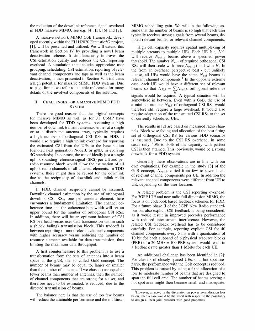
Figure 1 provides a high level illustration of the pro-posed concept, comprising the following components
1) The use of massive MIMO.2) Spatial multiplexing to more than 10 UE/cell.3) Use of network MIMO or inter site JT CoMP
precoder W over the relevant channel com-ponents generated by the GoB beamformermatrices V.
4) The use of coded CSI RS for accurate channelestimation with limited overhead for CSI RSs.
5) Beamformers on the UE with up to 8 antennaelements that increase the sparsity of the over-all downlink channel matrix H, which includesthe transmit GoB and receive filters.
6) CSI reporting per relevant taps and relevantchannel components minimizing the feedbackoverhead to the relevant information. Channelsare predicted for moving UEs, see [10], [13].
7) Use of interference floor shaping to reduceinter-cluster interference, e.g., based on thecover shift concept as well as the tortoiseconcept [14].
As indicated in Figure 1, ideally the target per-formance is a factor 7 - 10 higher spectral efficiencyas compared to a LTE 4x4 system, while keeping areasonable overhead for CSI RSs of about 5% - 10% aswell as a reasonable overhead for CSI feedback.
Fig. 1: Interference Mitigation framework based onmassive MIMO and JT CoMP in an FDD setting.
IV. BEAM DEACTIVATION FOR MASSIVE MIMOFDD SYSTEMS
Sparsity is the key for attaining a workable FDDmassive MIMO system. So why then send CSI RSin beams that are not relevant to any UE? Dynamicbeam deactivation would lower the CSI RS power.This improves the channel estimation accuracy whenused in combination with coded CSI RSs, since itreduces the inter-code interference due to the code non-orthogonality. It will also improve the power efficiencyand reduce the inter-cell interference and also the CSIfeedback overhead. We will here discuss an optimumbeam management or beam deactivation scheme as anextension to the overall massive MIMO GoB frameworkof Figure 1.
For a single UE, beam deactivation would be quitestraightforward, for example by switching off all ir-relevant beams, i.e., those of the transmit beams thatwould be received below a specified power threshold,on average over the short-term fading.
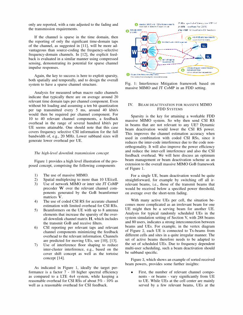
With many active UEs per cell, the situation be-comes more complicated as an irrelevant beam for oneUE might then be a serving beam for another UE.Analysis for typical randomly scheduled UEs in thesystem simulation setting of Section V, with 288 beamsand 80 users, indicates a strong interconnection betweenbeams and UEs. For example, in the vertex diagramof Figure 2, each UE is connected to Tx-beams fromdifferent cells and sites in a quite irregular manner. Theset of active beams therefore needs to be adapted tothe set of scheduled UEs. Due to frequency dependentmulti-user scheduling, such a beam deactivation shouldbe subband specific.
Figure 3, which shows an example of sorted receivedbeam powers, provides some further insights:
• First, the number of relevant channel compo-nents - or beams - vary significantly from UEto UE. While UEs at the cell center are mainlyserved by a few relevant beams, UEs at the

border to several cells might receive 50 or morebeams as relevant channel components. For thatreason, a simple CSI feedback framework witha fixed number of reported channel componentsseems to be inadequate.
• Second, almost all UEs experience an inter-ference floor where a high number of beamsare received with a power close to the rele-vant channel component power threshold PTH .These beams will not be reported, but dueto their high number of 50 or more chan-nel components, the sum of their (neglected)powers would generate a strong inter streaminterference for a fully loaded system.
• Third, there are Tx-beams, which are receivedwell below the power of the relevant channelcomponents - like minus 30 to 40 dB belowthe strongest channel component - and thereforedo not affect the performance of a zero-forcing(ZF) precoder at all.
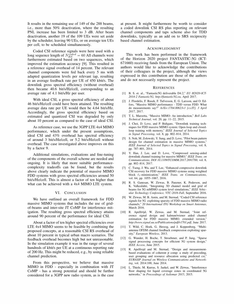
In Figure 4 these three regions are illustrated withthe relevant, the interference floor and the irrelevantchannel beams.
A further challenge is that some of the UEs havethe same beam, or subset of beams, as their strongestserving beam(s). This can be concluded from a deeperanalysis of the vertex diagram in Figure 2. The typicalhigh correlation of these radio channels will often leadto a high power normalization loss (PNL) for zero-forcing-like linear precoders and this PNL will degradethe overall performance.
To alleviate this problem, the UEs that would gen-erate a very high PNL if admitted - even with all beamsactive - should be removed from the served multi-userset. A separate subband with a different setup of activebeams should be used to serve these users.
For the remaining UEs, the best zero forcing precod-ing performance (under the assumption of ideal CSI)is attained when all Nbeam beams are active, as thiswill lead to the lowest condition number of the overallchannel matrix H ∈ CKxNbeam . However, the corre-sponding overhead for CSI RSs and CSI reporting forsuch a large cooperation area can be reduced. Togetherwith the observations from Figure 4, we end up ina multidimensional non-convex optimization problem,with the following, partly conflicting, goals:
We should find the best beam deactivation patternfor a defined set of scheduled UEs, such that
• the number of beams that contribute to theinterference floors of the different UEs shouldbe reduced,
• also, the number of relevant channel compo-nents should be reduced to lower the feedbackoverhead, but
• this has to be done while causing a not too largeextra power normalization loss, as compared tothe case when all beams are active.
It is proposed to use an iterative optimization of aweighted cost function:
{Bopt|Ksched} = argmin(α1PNL(Bl)+α2Nrel(Bl) + α3NIF (Bl)) ;
PNL(Bl) =∑‖wij‖2; with wij = Wl
ij ;
Wl = pinv(Hbeam(Bl,Ksched)) ,(1)
with α1, α2 and α3 being scalar weight factors, definingthe relative importance of the PNL, the number Nrel
of relevant channel components and the number NIF
of interference floor channel components. Here, Ksched
is the currently scheduled set of UEs, Hbeam(·, ·) ∈CKxNbeam is the overall channel matrix for all Nbeam
beams and all K UEs, but with rows and column set tozero according to the beam deactivation and schedul-ing assumed in iteration l. Then, with pseudoinversepinv(·), Wl is the joint linear precoding matrix atiteration l.
Here, Bl is the combination or set of active beams{b1 · · · bNbeam
} at iteration l, with bl ∈ 0, 1, i.e., bl =1/0 indicating an active or inactive beam.
Also, Nrel(Bl) is the overall number of relevantchannel components, for which the Rx power of beamj at some UE i is PRx(Hij) > PTH .
Finally, NIF is the number of channel compo-nents forming the interference floor, for which PTH ≥PRx(Hij) > PTH,IF for some UE i, where PTH,IF isthe threshold power for the interference floor. Note, Hij
- and accordingly Hbeam - is column wise normalizedto the strongest beam per UE .
In the iterative approach, beams are deactivated oneby one. At each iteration l, the beam that generatesthe largest decrease of the cost function when removedwill be deactivated. The final optimum beam set Boptis then obtained, for example, by defining a maximumallowed PNL value PNLmax and choosing the beamset that generates a PNL just below PNLmax. Thereduction of the number of relevant channel componentsbrings a benefit due to the reduced feedback over-head. The reduced number of interference floor channelcomponents furthermore significantly reduces the inter-stream interference. Depending on the situation, thisoften outweighths the additional PNL loss as comparedto full beam activation due to the resulting reduced inter-stream interference.
V. SIMULATION RESULTS
The proposed concept has been simulated for a ninecell cooperation area with a massive MIMO antenna per
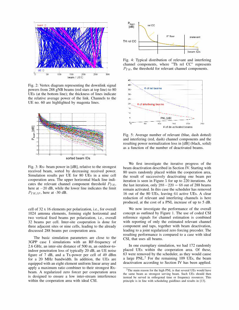
Fig. 2: Vertex diagram representing the downlink signalpowers from 288 gNB beams (red stars at top line) to 80UEs (at the bottom line); the thickness of lines indicatethe relative average power of the link. Channels to theUE no. 60 are highlighted by magenta lines.
Fig. 3: Rx- beam power in [dB], relative to the strongestreceived beam, sorted by decreasing received power.Simulation results per UE for 80 UEs in a nine cellcooperation area. The upper horizontal black line indi-cates the relevant channel component threshold PTH ,here at −20 dB, while the lower line indicates the limitPTH,IF , here at -30 dB.
cell of 32 x 16 elements per polarization, i.e., for overall1024 antenna elements, forming eight horizontal andtwo vertical fixed beams per polarization, i.e., overall32 beams per cell. Inter-site cooperation is done forthree adjacent sites or nine cells, leading to the alreadydiscussed 288 beams per cooperation area.
The basic simulation parameters are close to the3GPP case I simulations with an RF-frequency of2.6 GHz, an inter-site distance of 500 m, an outdoor-to-indoor penetration loss of typically 20 dB, an UE noisefigure of 7 dB, and a Tx-power per cell of 49 dBmfor a 20 MHz bandwidth. In addition, the UEs areequipped with an eight element uniform linear array andapply a maximum ratio combiner to their strongest Rx-beam. A regularized zero forcer per cooperation areais designed to ensure a low inter-stream interferencewithin the cooperation area with ideal CSI.
Fig. 4: Typical distribution of relevant and interferingchannel components, where ”Th rel CC” representsPTH , the threshold for relevant channel components.
Fig. 5: Average number of relevant (blue, dash dotted)and interfering (red, dash) channel components and theresulting power normalization loss in [dB] (black, solid)as a function of the number of deactivated beams.
We first investigate the iterative progress of thebeam deactivation described in Section IV. Starting with80 users randomly placed within the cooperation area,the result of successively deactivating one beam periteration is seen in Figure 5 for up to 220 iterations. Atthe last iteration, only 288−220 = 68 out of 288 beamsremain activated. In this case the scheduler has removed16 out of the 80 UEs, leaving 64 active UEs. A clearreduction of relevant and interfering channels is hereproduced, at the cost of a PNL increase of up to 5 dB.
We now investigate the performance of the overallconcept as outlined by Figure 1. The use of coded CSIreference signals for channel estimation is combinedwith reporting of only the estimated relevant channelcomponent and taps, together with beam deactivation,leading to a joint regularized zero forcing precoder. Theresulting performance is compared to a case with idealCSI, that uses all beams.
In one exemplary simulation, we had 172 randomlyplaced UEs within the cooperation area. Of these,63 were removed by the scheduler, as they would causea large PNL.2 For the remaining 109 UEs, the beamdeactivation according to Section IV has been applied.
2The main reason for the high PNL is that several UEs would havethe same beam as strongest serving beam. Such UEs should theninstead be served in orthogonal time or frequency resources. Thisprinciple is in line with scheduling guidlines and results in [13].
It results in the remaining use of 149 of the 288 beams,i.e., more than 50% deactivation, where the resultingPNL increase has been limited to 3 dB. After beamdeactivation, another 19 of the 109 UEs were set asideby the scheduler, leaving 90 UEs, or on average ten UEsper cell, to be scheduled simultaneously.
Coded CSI reference signals were here used with along sequence length of N coded
RS = 60 All channels werefurthermore estimated based on two sequences, whichimproved the estimation accuracy [9]. This resulted ina reference signal overhead of 14 percent. The relevantchannel components were fed back every 5 ms withadapted quantization levels per relevant tap, resultingin an average feedback rate per UE of 450 kbit/s. Thedownlink gross spectral efficiency (without overhead)then became 40.6 bit/s/Hz/cell, corresponding to anaverage rate of 4.1 bit/s/Hz per user.
With ideal CSI, a gross spectral efficiency of about46 bit/s/Hz/cell could have been attained. The resultingaverage data rate per UE would then be 4.64 bit/s/Hz.Accordingly, the gross spectral efficiency based onestimated and quantized CSI was degraded by onlyabout 10 percent as compared to the case of ideal CSI.
As reference case, we use the 3GPP LTE 4x4 MIMOperformance, which under the present assumptions,ideal CSI and 43% overhead has spectral efficiencyof around 3 bit/s/Hz/cell, or 5.2 bit/s/Hz/cell withoutoverhead. The case investigated above improves on thisby a factor 9.
Additional simulations, evaluations and fine-tuningof the components of the overall scheme are needed andongoing. It is likely that more suitable performance-complexity tradeoffs can be found, but the resultsabove clearly indicate the potential of massive MIMOFDD systems with gross spectral efficiencies around 50bit/s/Hz/cell. This is almost a factor of ten higher thanwhat can be achieved with a 4x4 MIMO LTE system.
VI. CONCLUSION
We have outlined an overall framework for FDDmassive MIMO systems that includes the use of grid-of-beams and inter-site JT CoMP for interference mit-igation. The resulting gross spectral efficiency attainsaround 90 percent of the performance for ideal CSI.
About a factor of ten higher spectral efficiencies overLTE 4x4 MIMO seems to be feasible by combining theproposed concepts, at a reasonable CSI RS overhead ofabout 10 percent in typical urban macro scenarios. Thefeedback overhead becomes high but not unreasonable.In the simulation example it was in the range of severalhundreds of kbit/s per UE at a continuous reporting rateof 200 Hz. This might be reduced, e.g., by using reliablechannel prediction.
From this perspective, we believe that massiveMIMO in FDD - especially in combination with JTCoMP - has a strong potential and should be furtherconsidered for a 3GPP new radio system, as is the case
at present. It might furthermore be worth to considera coded downlink CSI RS plus reporting on relevantchannel components and taps scheme also for TDDdownlinks, typically as an add on to SRS reciprocitybased channel estimation.
ACKNOWLEDGMENT
This work has been performed in the frameworkof the Horizon 2020 project FANTASTIC-5G (ICT-671660) receiving funds from the European Union. Theauthors would like to acknowledge the contributionsof their colleagues in the project, although the viewsexpressed in this contribution are those of the authorsand do not necessarily represent the project.
REFERENCES
[1] B. S. et. al., “Fantastic5G deliverable D4.2,” EU H2020-ICT-2014-2 Fantastic5G, http://fantastic5G.eu, April 2017.
[2] J. Flordelis, F. Rusek, F. Tufvesson, E. G. Larsson, and O. Ed-fors, “Massive MIMO performance - TDD versus FDD: Whatdo measurements say?” ArXiv:1704.00623v1 [cs.IT], 3 April2017, 2017.
[3] T. L. Marzetta, “Massive MIMO: An introduction,” Bell LabsTechnical Journal, vol. 20, pp. 11–22, 2015.
[4] J. Choi, D. Love, and P. Bidigare, “Downlink training tech-niques for FDD massive MIMO system: Open-loop and closed-loop training with memory,” IEEE Journal of Selected Topicsin Signal Processing, vol. 8, pp. 802–814, 2014.
[5] S. Noh, M. Zolowski, Y. Sung, and D. Love, “Pilot beam patterndesign for channel estimation in massive MIMO systems,”IEEE Journal of Selected Topics in Signal Processing, vol. 8,pp. 787–801, 2014.
[6] Y. Han, J. Lee, and D. Love, “Compressed sensing-aideddownlink channel training for massive MIMO,” IEEE Trans. onCommunications, DOI 10.1109/TCOMM.2017.2691700, vol. 8,pp. 802–814, 2017.
[7] C. Tseng, J. Wu, and T. Lee, “Enhanced compressive downlinkCSI recovery for FDD massive MIMO systems using weightedblock `1-minimization,” IEEE Trans. on Communications,vol. 64, pp. 1055–1067, 2016.
[8] R. S. Ganesan, W. Zirwas, B. Panzner, K. Pederson, andK. Valkealahti, “Integrating 3D channel model and grid ofbeams for 5G mMIMO system level simulations,” IEEE Vehic-ular Technology Conference, VTC-2016-Fall, September 2016.
[9] W. Zirwas, M. B. Amin, and M. Sternad, “Coded CSI referencesignals for 5G exploiting sparsity of FDD massive MIMO radiochannels,” 20 International ITG Workshop on Smart Antennas,March 2016.
[10] R. Apelfrojd, W. Zirwas, and M. Sternad, “Joint ref-erence signal design and kalman/wiener aided channelestimation for FDD massive MIMO. extended version,”http://www.signal.uu.se/Publications/pdf/r1701.pdf, June 2017.
[11] T. Wild, C. Hoek, G. Herzog, and J. Koppenborg, “Multi-antenna OFDM channel feedback compression exploiting spar-sity,” European Wireless, 2013.
[12] G. Wunder, H. Boche, T. Stroehmer, and P. Jung, “Sparsesignal processing concepts for efficient 5G system design,”IEEE Access, June 2015.
[13] R. Apelfrojd and M. Sternad, “Design and measurement-based evaluations of coherent jt comp: a study of precoding,user grouping and resource allocation using predicted csi,”EURASIP Journal on Wireless Communications and Network-ing, vol. 2014:100, June 2014.
[14] L. Thiele, M. Kurras, S. Jaekel, and W. Zirwas, “Interferencefloor shaping for liquid coverage zones in coordinated 5Gnetworks,” in Proceedings of Asilomar 2015, 2015.