Embed Size (px)
Citation preview

KEYPAD & LCD
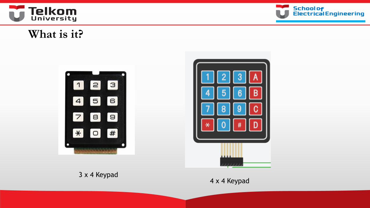
What is it?
3 x 4 Keypad4 x 4 Keypad
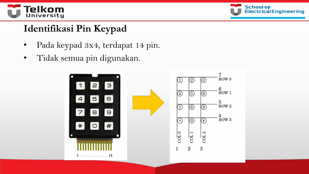
Identifikasi Pin Keypad
• Pada keypad 3x4, terdapat 14 pin.
• Tidak semua pin digunakan.
Library Keypad di Arduino
• Library keypad di arduino memiliki sifat non-blocking yang berati kita dapat menekan dan menahan tombol selama yang diinginkan, dan Arduino tetap memproses instruksi-instruksi selanjutnya.
• Ketika menggunakan instruksi delay() akan mempengaruhi waktu respon keypad. Gunakan instruksi delay() yang cukup, jangan terlalu lama seperti delay (250), hal ini akan menyebabkan keypad terasa tidak responsif
• Fungsi getKey() menghasilkan nilai sesuai yang diassign ke tombol tertentu.
Contoh
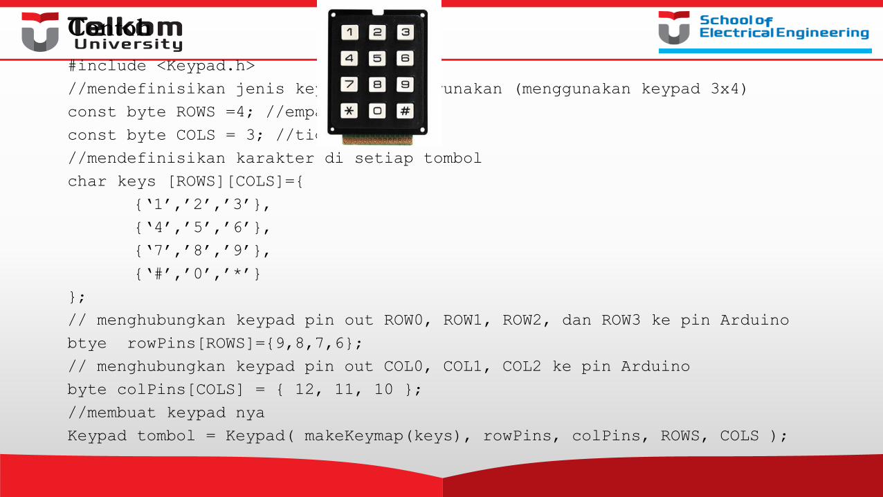
#include <Keypad.h>
//mendefinisikan jenis keypad yang digunakan (menggunakan keypad 3x4)
const byte ROWS =4; //empat baris
const byte COLS = 3; //tiga kolom
//mendefinisikan karakter di setiap tombol
char keys [ROWS][COLS]={
{‘1’,’2’,’3’},
{‘4’,’5’,’6’},
{‘7’,’8’,’9’},
{‘#’,’0’,’*’}
};
// menghubungkan keypad pin out ROW0, ROW1, ROW2, dan ROW3 ke pin Arduino
btye rowPins[ROWS]={9,8,7,6};
// menghubungkan keypad pin out COL0, COL1, COL2 ke pin Arduino
byte colPins[COLS] = { 12, 11, 10 };
//membuat keypad nya
Keypad tombol = Keypad( makeKeymap(keys), rowPins, colPins, ROWS, COLS );

#define ledpin 13
Void setup(){
pinMode(ledpin,OUTPUT);
digitalWrite(ledpin,HIGH);
Serial.begin(9600);
}
Void loop(){
char key =tombol.getKey();
if(key){ // cek tombol yang valid
switch(key){
case’*’:
digitalWrite(ledpin, LOW);
break;
case ‘#’:
digitalWrite(ledpin, LOW);
break;
default:
Serial.println(key);
}
}
}
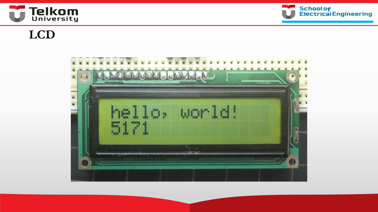
LCD
Pin LCD
• The LCDs have a parallel interface, meaning that the microcontroller has to manipulate several interface pins at once to control the display.
• The interface consists of the following pins:
1. register select (RS) pin that controls where in the LCD's memory you're writing data to. You can select either the data register, which holds what goes on the screen, or an instruction register, which is where the LCD's controller looks for instructions on what to do next.
2. Read/Write (R/W) pin that selects reading mode or writing mode
Pin LCD
3. Enable pin that enables writing to the registers
4. 8 data pins (D0 -D7). The states of these pins (high or low) are the bits that you're writing to a register when you write, or the values you're reading when you read.
5. Display constrast pin (Vo), power supply pins (+5V and Gnd) and LED Backlight (Bklt+ and BKlt-) pins that you can use to power the LCD, control the display contrast, and turn on and off the LED backlight, respectively.
Library LCD untuk Arduino
• The process of controlling the display involves putting the data that form the image of what you want to display into the data registers, then putting instructions in the instruction register.
• The LiquidCrystal Library simplifies this for you so you don't need to know the low-level instructions.
LCD
• The Hitachi-compatible LCDs can be controlled in two modes: 4-bit or 8-bit.
• The 4-bit mode requires seven I/O pins from the Arduino, while the 8-bit mode requires 11 pins.
• For displaying text on the screen, you can do most everything in 4-bit mode, so example shows how to control a 2x16 LCD in 4-bit mode.
Tugas: Buat di Circuits.io, screen shoot hasilnya lalu posting di blog
Kebutuhan hardware:
• Arduino or Genuino Board
• LCD Screen (compatible with Hitachi HD44780 driver)
• pin headers to solder to the LCD display pins
• 10k ohm potentiometer
• 220 ohm resistor
• hook-up wires
• breadboard
Tugas
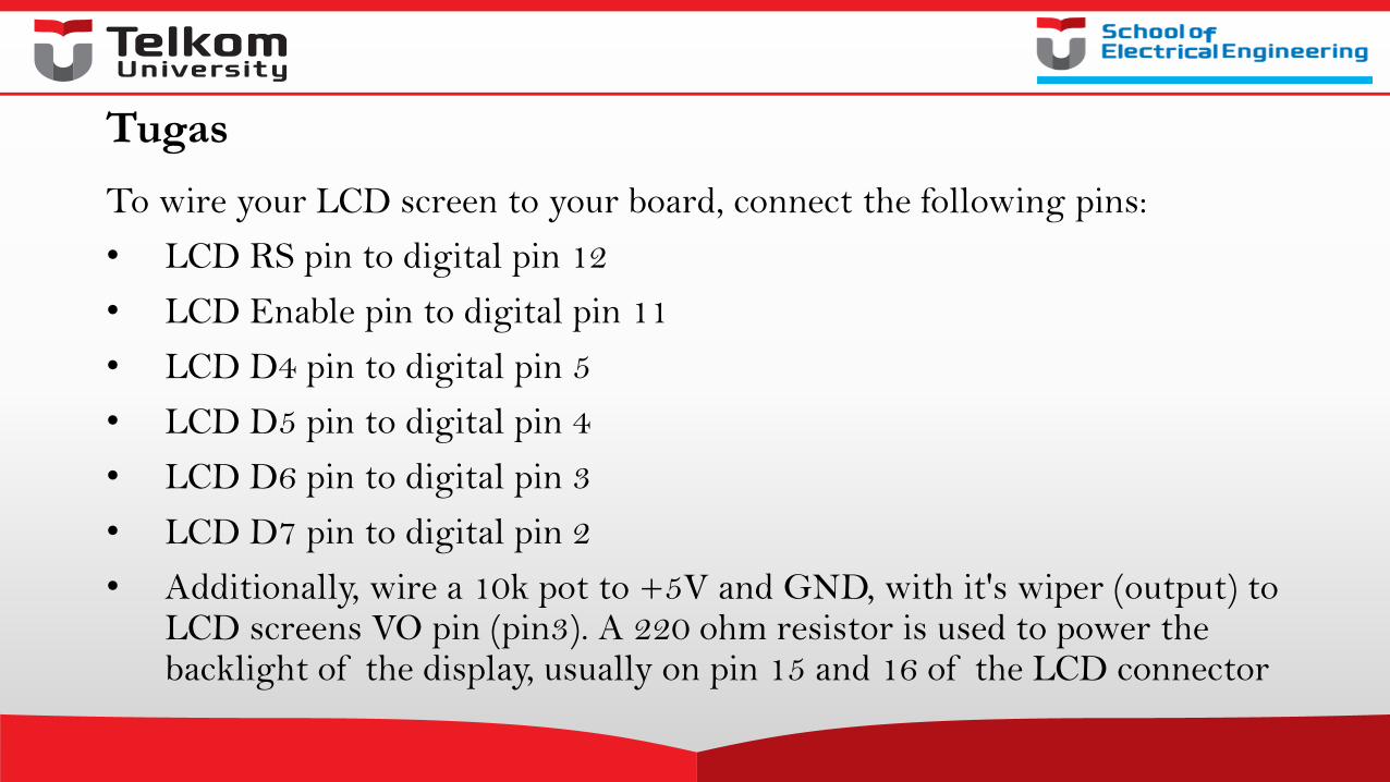
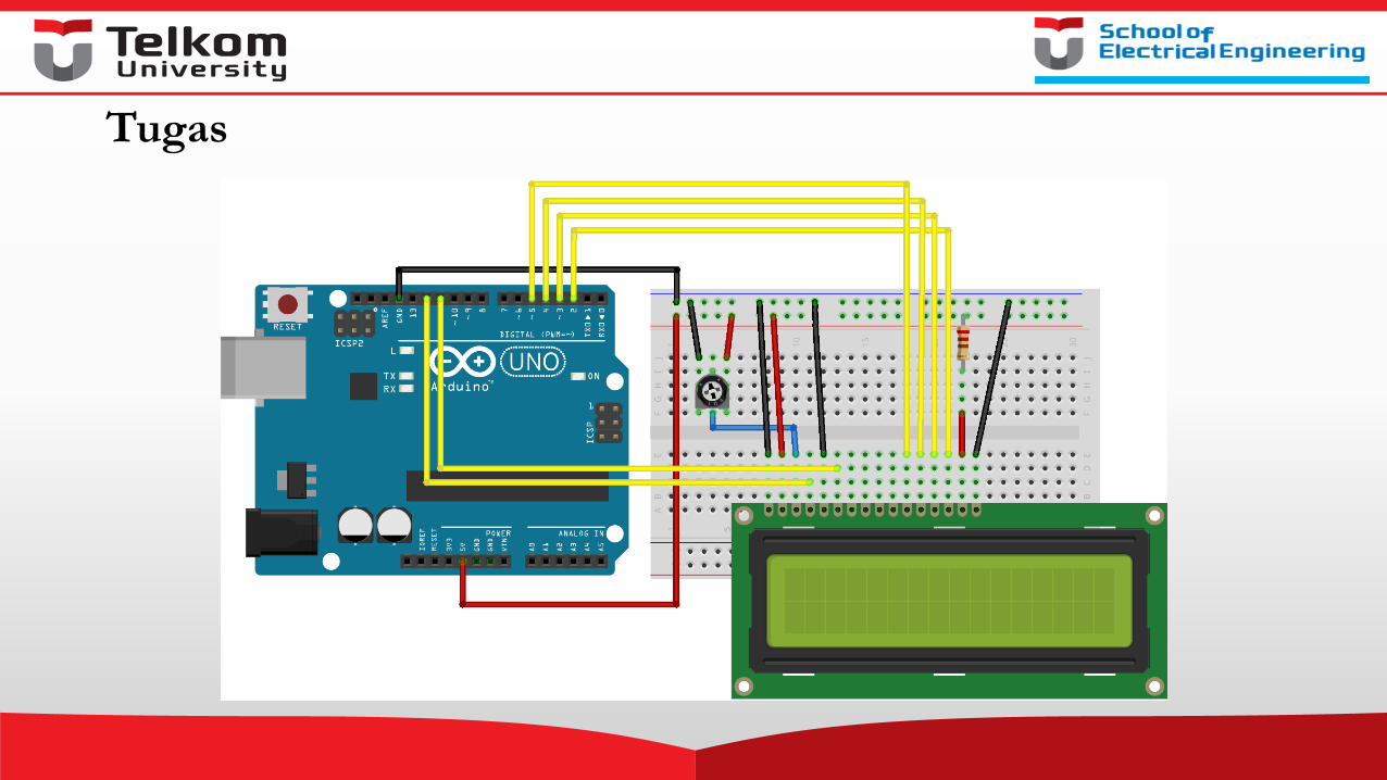
To wire your LCD screen to your board, connect the following pins:
• LCD RS pin to digital pin 12
• LCD Enable pin to digital pin 11
• LCD D4 pin to digital pin 5
• LCD D5 pin to digital pin 4
• LCD D6 pin to digital pin 3
• LCD D7 pin to digital pin 2
• Additionally, wire a 10k pot to +5V and GND, with it's wiper (output) to LCD screens VO pin (pin3). A 220 ohm resistor is used to power the backlight of the display, usually on pin 15 and 16 of the LCD connector
Tugas
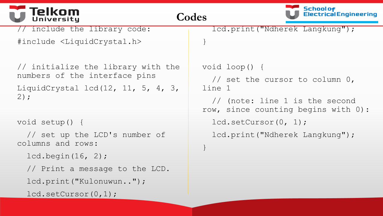
Codes// include the library code:
#include <LiquidCrystal.h>
// initialize the library with the
numbers of the interface pins
LiquidCrystal lcd(12, 11, 5, 4, 3,
2);
void setup() {
// set up the LCD's number of
columns and rows:
lcd.begin(16, 2);
// Print a message to the LCD.
lcd.print("Kulonuwun..");
lcd.setCursor(0,1);
lcd.print("Ndherek Langkung");
}
void loop() {
// set the cursor to column 0,
line 1
// (note: line 1 is the second
row, since counting begins with 0):
lcd.setCursor(0, 1);
lcd.print("Ndherek Langkung");
}
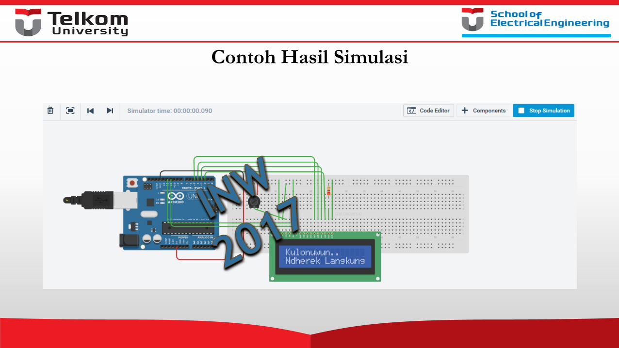
Contoh Hasil Simulasi