Embed Size (px)
Citation preview
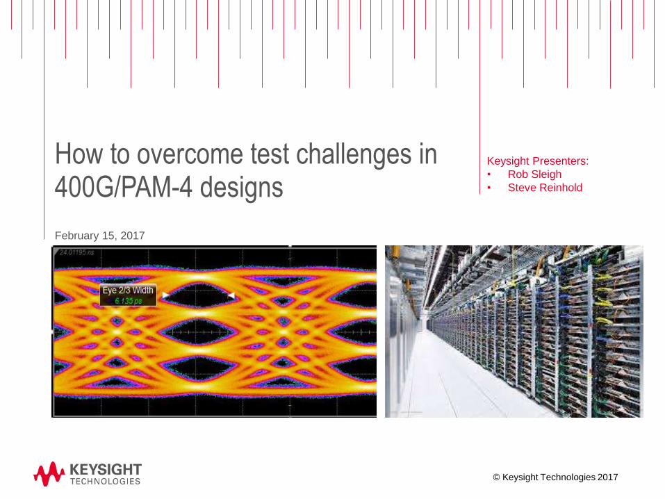
How to overcome test challenges in 400G/PAM-4 designs
Keysight Presenters:
• Rob Sleigh
• Steve Reinhold
February 15, 2017
© Keysight Technologies 2017
Page
Overcoming test
challenges in
400G/PAM-4 designs
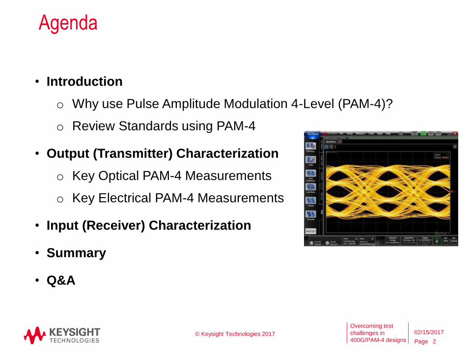
Agenda
• Introduction
o Why use Pulse Amplitude Modulation 4-Level (PAM-4)?
o Review Standards using PAM-4
• Output (Transmitter) Characterization
o Key Optical PAM-4 Measurements
o Key Electrical PAM-4 Measurements
• Input (Receiver) Characterization
• Summary
• Q&A
© Keysight Technologies 2017
2
02/15/2017
Page
Overcoming test
challenges in
400G/PAM-4 designs
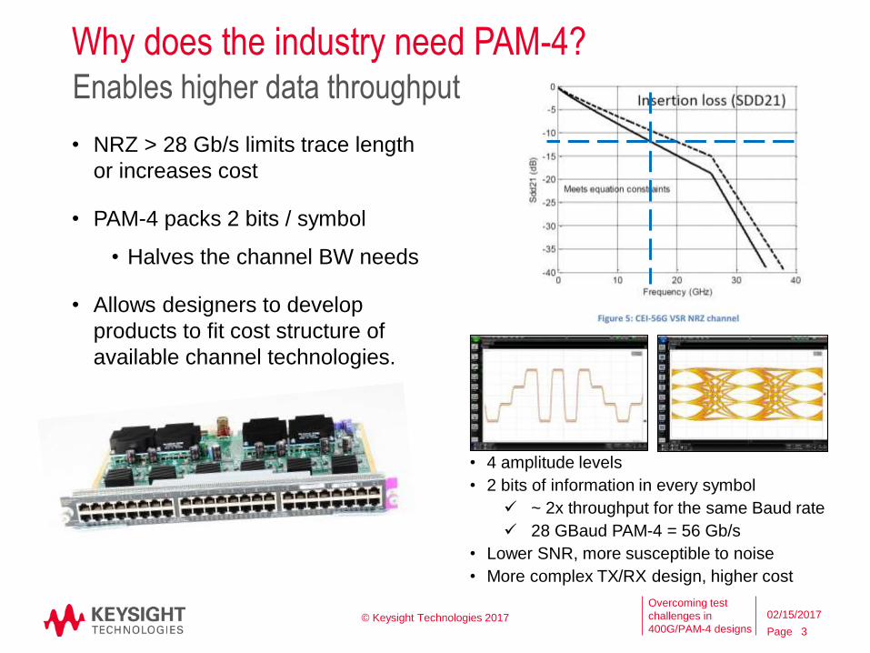
Why does the industry need PAM-4?
• NRZ > 28 Gb/s limits trace length
or increases cost
• PAM-4 packs 2 bits / symbol
• Halves the channel BW needs
• Allows designers to develop
products to fit cost structure of
available channel technologies.
Enables higher data throughput
• 4 amplitude levels
• 2 bits of information in every symbol
~ 2x throughput for the same Baud rate
28 GBaud PAM-4 = 56 Gb/s
• Lower SNR, more susceptible to noise
• More complex TX/RX design, higher cost
© Keysight Technologies 2017
3
02/15/2017
Page
Overcoming test
challenges in
400G/PAM-4 designs
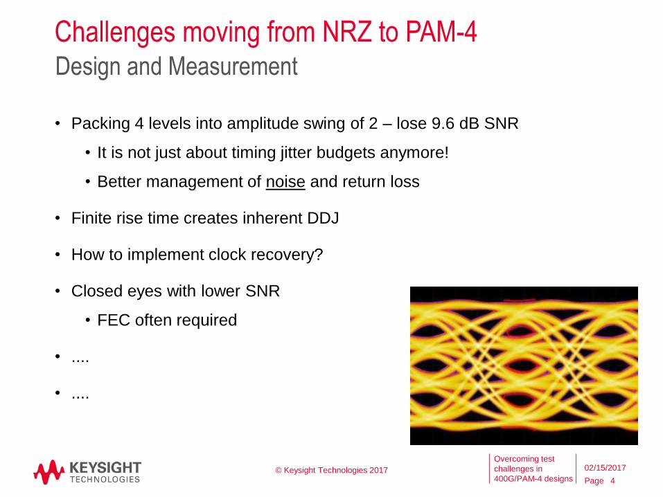
Challenges moving from NRZ to PAM-4Design and Measurement
• Packing 4 levels into amplitude swing of 2 – lose 9.6 dB SNR
• It is not just about timing jitter budgets anymore!
• Better management of noise and return loss
• Finite rise time creates inherent DDJ
• How to implement clock recovery?
• Closed eyes with lower SNR
• FEC often required
• ....
• ....
© Keysight Technologies 2017
4
02/15/2017
Page
Overcoming test
challenges in
400G/PAM-4 designs
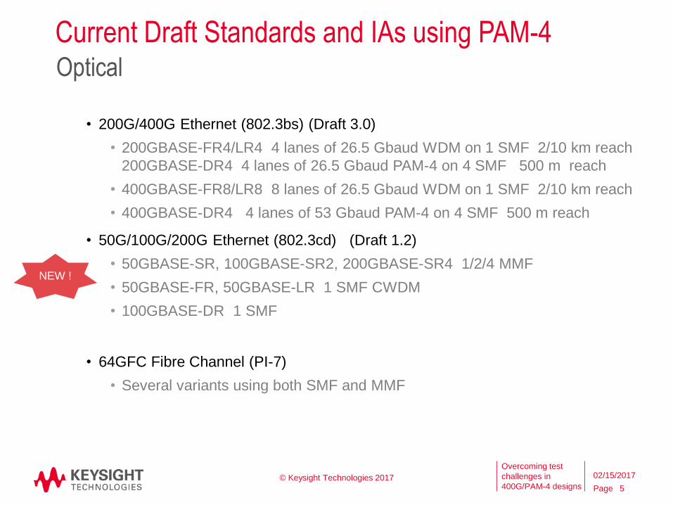
Current Draft Standards and IAs using PAM-4
• 200G/400G Ethernet (802.3bs) (Draft 3.0)
• 200GBASE-FR4/LR4 4 lanes of 26.5 Gbaud WDM on 1 SMF 2/10 km reach
200GBASE-DR4 4 lanes of 26.5 Gbaud PAM-4 on 4 SMF 500 m reach
• 400GBASE-FR8/LR8 8 lanes of 26.5 Gbaud WDM on 1 SMF 2/10 km reach
• 400GBASE-DR4 4 lanes of 53 Gbaud PAM-4 on 4 SMF 500 m reach
• 50G/100G/200G Ethernet (802.3cd) (Draft 1.2)
• 50GBASE-SR, 100GBASE-SR2, 200GBASE-SR4 1/2/4 MMF
• 50GBASE-FR, 50GBASE-LR 1 SMF CWDM
• 100GBASE-DR 1 SMF
• 64GFC Fibre Channel (PI-7)
• Several variants using both SMF and MMF
Optical
NEW !
© Keysight Technologies 2017
5
02/15/2017
Page
Overcoming test
challenges in
400G/PAM-4 designs
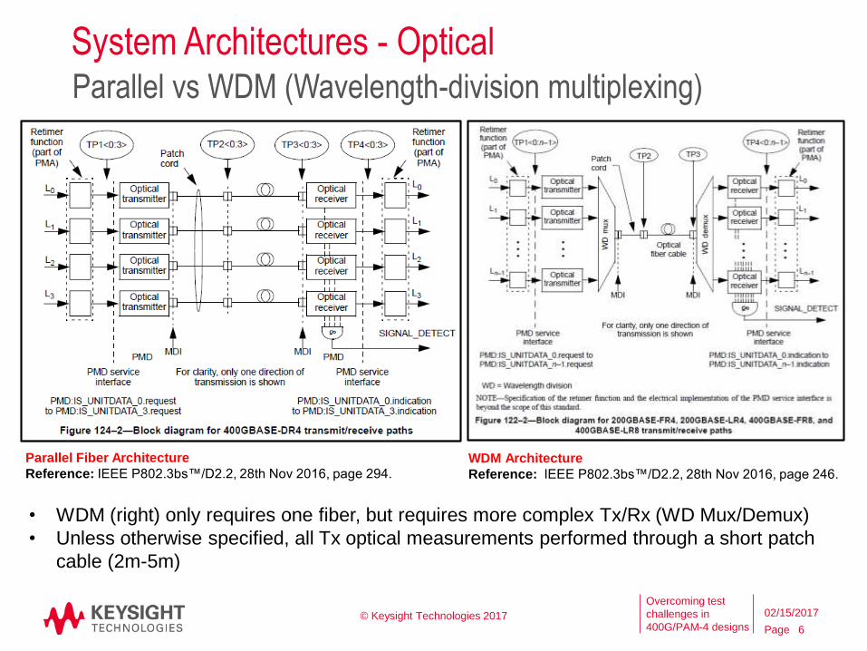
System Architectures - OpticalParallel vs WDM (Wavelength-division multiplexing)
• WDM (right) only requires one fiber, but requires more complex Tx/Rx (WD Mux/Demux)
• Unless otherwise specified, all Tx optical measurements performed through a short patch
cable (2m-5m)
Parallel Fiber Architecture
Reference: IEEE P802.3bs™/D2.2, 28th Nov 2016, page 294.WDM Architecture
Reference: IEEE P802.3bs™/D2.2, 28th Nov 2016, page 246.
© Keysight Technologies 2017
6
02/15/2017
Page
Overcoming test
challenges in
400G/PAM-4 designs
Current Draft Standards and IAs using PAM-4
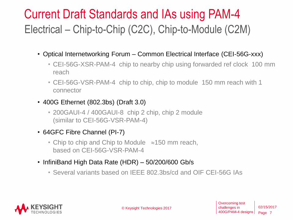
• Optical Internetworking Forum – Common Electrical Interface (CEI-56G-xxx)
• CEI-56G-XSR-PAM-4 chip to nearby chip using forwarded ref clock 100 mm
reach
• CEI-56G-VSR-PAM-4 chip to chip, chip to module 150 mm reach with 1
connector
• 400G Ethernet (802.3bs) (Draft 3.0)
• 200GAUI-4 / 400GAUI-8 chip 2 chip, chip 2 module
(similar to CEI-56G-VSR-PAM-4)
• 64GFC Fibre Channel (PI-7)
• Chip to chip and Chip to Module 150 mm reach,
based on CEI-56G-VSR-PAM-4
• InfiniBand High Data Rate (HDR) – 50/200/600 Gb/s
• Several variants based on IEEE 802.3bs/cd and OIF CEI-56G IAs
Electrical – Chip-to-Chip (C2C), Chip-to-Module (C2M)
© Keysight Technologies 2017
7
02/15/2017
Page
Overcoming test
challenges in
400G/PAM-4 designs
Current Draft Standards and IAs using PAM-4
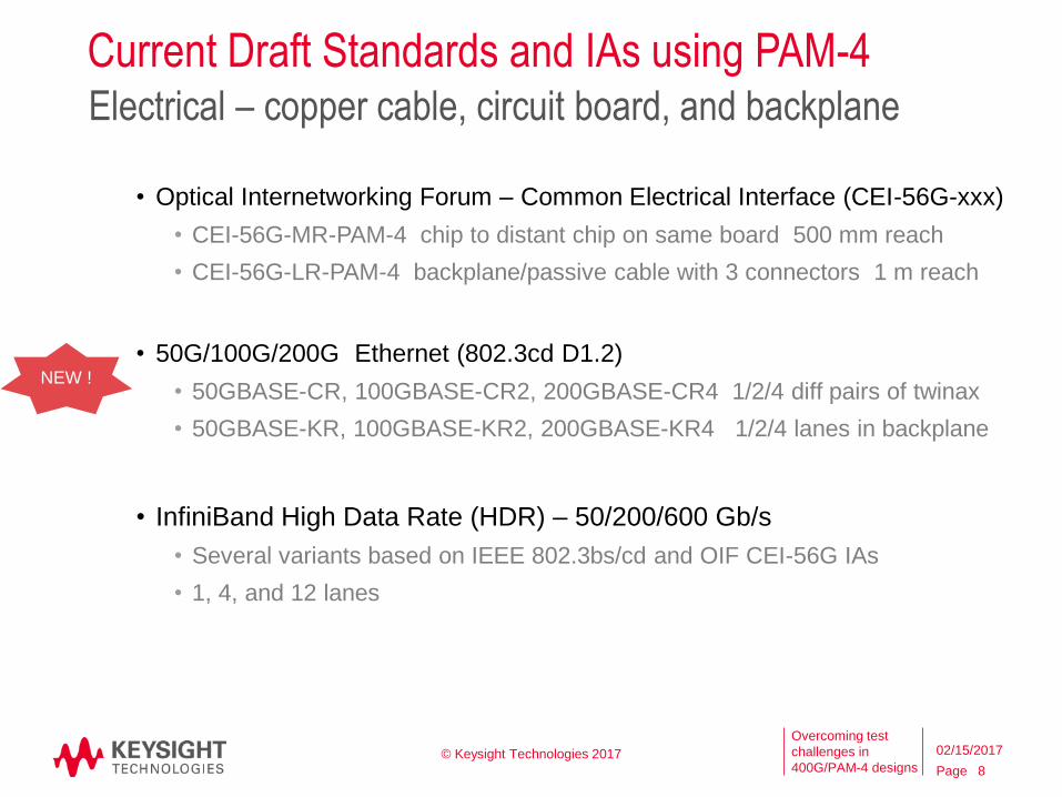
• Optical Internetworking Forum – Common Electrical Interface (CEI-56G-xxx)
• CEI-56G-MR-PAM-4 chip to distant chip on same board 500 mm reach
• CEI-56G-LR-PAM-4 backplane/passive cable with 3 connectors 1 m reach
• 50G/100G/200G Ethernet (802.3cd D1.2)
• 50GBASE-CR, 100GBASE-CR2, 200GBASE-CR4 1/2/4 diff pairs of twinax
• 50GBASE-KR, 100GBASE-KR2, 200GBASE-KR4 1/2/4 lanes in backplane
• InfiniBand High Data Rate (HDR) – 50/200/600 Gb/s
• Several variants based on IEEE 802.3bs/cd and OIF CEI-56G IAs
• 1, 4, and 12 lanes
Electrical – copper cable, circuit board, and backplane
NEW !
© Keysight Technologies 2017
8
02/15/2017

Page
Overcoming test
challenges in
400G/PAM-4 designs
Overview of IEEE P802.3bs™/D3.0, 10th January 2017PAM-4 used in 200 Gb/s and 400 Gb/s Operation
Name # of lanesChannel
(Medium)Reach
Signaling Rate
(each lane)
Modulation
FormatReference Receiver Defined in IEEE
200GBASE-DR44
Parallel FibresSM 2m to 500 m 26.5625 GBd PAM4
TDECQ with 4th Order BT filter,
BW 19.34 GHzClause 121
200GBASE-FR44 WDM Lanes
(1 Fibre)SM 2m to 2 km 26.5625 GBd PAM4
TDECQ with 4th Order BT filter,
BW 19.34 GHzClause 122
200GBASE-LR44 WDM Lanes
(1 Fibre)SM 2m to 10 km 26.5625 GBd PAM4
TDECQ with 4th Order BT filter,
BW 19.34 GHzClause 122
200GAUI-8
(formerly CCAUI-8)8
Chip-to-Chip and
Chip-to-Module
~ 25 cm
10.2dB at 13.28 GHz26.5625 GBd NRZ
4th Order BT filter,
BW 33 GHzAnnex 120B/C
200GAUI-4
(formerly CCAUI-4)4
Chip-to-Chip and
Chip-to-Module
~ 25 cm
10.2dB at 13.28 GHz26.5625 GBd PAM4
4th Order BT filter,
BW 33 GHzAnnex 120D/E
400GBASE-SR1616
Parallel FibresMM 0.5 m to 100 m (OM4) 26.5625 GBd NRZ
TDEC with 4th Order BT filter,
BW 12.6 GHz
Eye Mask BW 19.38 GHz
Clause 123
400GBASE-DR44
Parallel FibresSM 2m to 500 m 53.125 GBd PAM4
TDECQ with 4th Order BT filter,
BW 38.68 GHzClause 124
400GBASE-FR88 WDM Lanes
(1 Fibre)SM 2m to 2 km 26.5625 GBd PAM4
TDECQ with 4th Order BT filter,
BW 19.34 GHzClause 122
400GBASE-LR88 WDM Lanes
(1 Fibre)SM 2m to 10 km 26.5625 GBd PAM4
TDECQ with 4th Order BT filter,
BW 19.34 GHzClause 122
400GAUI-16
(formerly CDAUI-16)16
Chip-to-Chip and
Chip-to-Module
~ 25 cm
10.2dB at 13.28 GHz26.5625 GBd NRZ
4th Order BT filter,
BW 33 GHzAnnex 120B/C
400GAUI-8
(formerly CDAUI-8)8
Chip-to-Chip and
Chip-to-Module
~ 25 cm
10.2dB at 13.28 GHz26.5625 GBd PAM4
4th Order BT filter,
BW 33 GHzAnnex 120D/E
IEEE
P8
02
.3b
s™ /
D2
.2 20
0 G
b/s
PH
Y
Op
tica
lEl
ect
rica
l
40
0 G
b/s
PH
Y
Op
tica
lEl
ect
rica
l
• Recent update (D3.0) includes changes to TDECQ and Jitter measurements
• Many “compliant” measurements require:
o Clock Recovery, Loop BW 4 MHz (all PAM-4)
o Reference Receiver with 4th Order Bessel-Thomson frequency response
© Keysight Technologies 2017 9
02/15/2017
IEE
E P
80
2.3
bs
™/ D
3.0
Page
Overcoming test
challenges in
400G/PAM-4 designs
Name # of lanesChannel
(Medium)Reach
Signaling Rate
(each lane)
Modulation
FormatReference Receiver Defined in IEEE
50GBASE-SR 1 Fibre MM Fibre0.5 m to 70 m for OM3
0.5 m to 100 m for OM426.5625 GBd PAM4
TDECQ with 4th Order BT filter,
BW 12.6 GHzClause 138
50GBASE-FR 1 Fibre SM Fibre 2 m to 2 km 26.5625 GBd PAM4TDECQ with 4th Order BT filter,
BW 19.34 GHzClause 139
50GBASE-LR 1 Fibre SM Fibre 2 m to 10 km 26.5625 GBd PAM4TDECQ with 4th Order BT filter,
BW 19.34 GHzClause 139
50GBASE-CR 1 Copper Cable > 3 m 26.5625 GBd PAM44th Order BT filter,
BW 33 GHzClause 136
50GBASE-KR 1Electrical
Backplane30dB at 13.28125GHz 26.5625 GBd PAM4
4th Order BT filter,
BW 33 GHzClause 137
100GBASE-DR 1 Fibre SM Fibre 2m to 500 m 53.125 GBd PAM4 TDECQ with 4th Order BT filter,
BW 38.68 GHzClause 140
100GBASE-SR22
Parallel FibresMM Fibre
0.5 m to 70 m for OM3
0.5 m to 100 m for OM426.5625 GBd PAM4
TDECQ with 4th Order BT filter,
BW 12.6 GHzClause 138
100GBASE-CR2 2 Copper Cable > 3 m 26.5625 GBd PAM44th Order BT filter,
BW 33 GHzClause 136
100GBASE-KR2 2Electrical
Backplane30dB at 13.28125GHz 26.5625 GBd PAM4
4th Order BT filter,
BW 33 GHzClause 137
Op
tica
l
200GBASE-SR44
Parallel FibresMM Fibre
0.5 m to 70 m for OM3
0.5 m to 100 m for OM426.5625 GBd PAM4
TDECQ with 4th Order BT filter,
BW 12.6 GHzClause 138
200GBASE-CR4 4 Copper Cable > 3 m 26.5625 GBd PAM44th Order BT filter,
BW 33 GHzClause 136
200GBASE-KR4 4Electrical
Backplane35dB at 12.9GHz 26.5625 GBd PAM4
4th Order BT filter,
BW 33 GHzClause 137
Ele
ctri
cal
Op
tica
l
50
Gb
/s P
HY
IEEE
P8
02
.3cd
™ /
D1
.0
10
0 G
b/s
PH
Y
Op
tica
l
20
0 G
b/s
PH
Y
Ele
ctri
cal
Ele
ctri
cal
IEE
E P
80
2.3
cd
™ / D
1.1
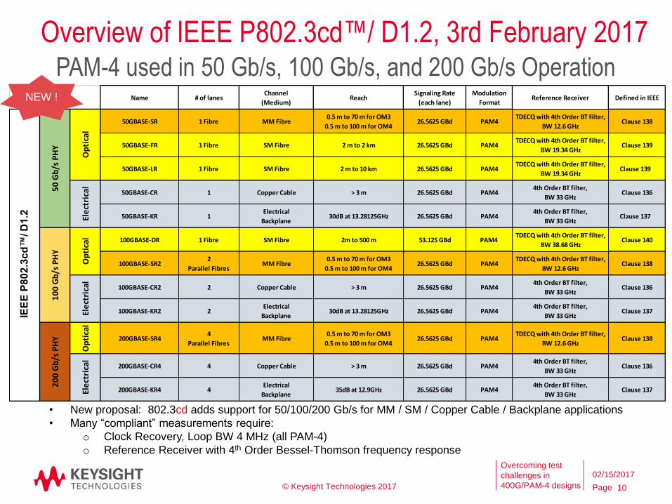
Overview of IEEE P802.3cd™/ D1.2, 3rd February 2017PAM-4 used in 50 Gb/s, 100 Gb/s, and 200 Gb/s Operation
• New proposal: 802.3cd adds support for 50/100/200 Gb/s for MM / SM / Copper Cable / Backplane applications
• Many “compliant” measurements require:
o Clock Recovery, Loop BW 4 MHz (all PAM-4)
o Reference Receiver with 4th Order Bessel-Thomson frequency response
NEW !
© Keysight Technologies 2017 10
02/15/2017
IEE
E P
80
2.3
cd
™/ D
1.2
Page
Overcoming test
challenges in
400G/PAM-4 designs
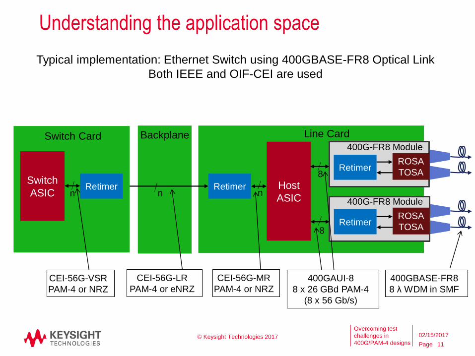
Understanding the application space
Typical implementation: Ethernet Switch using 400GBASE-FR8 Optical Link
Both IEEE and OIF-CEI are used
Line Card
Host
ASICRetimer
n
400G-FR8 Module
RetimerROSA
TOSA
400G-FR8 Module
RetimerROSA
TOSA
8
8
Backplane
n
Switch Card
Retimern
Switch
ASIC
400GAUI-8
8 x 26 GBd PAM-4
(8 x 56 Gb/s)
CEI-56G-MR
PAM-4 or NRZ
CEI-56G-LR
PAM-4 or eNRZ
CEI-56G-VSR
PAM-4 or NRZ
400GBASE-FR8
8 λ WDM in SMF
© Keysight Technologies 2017
11
02/15/2017
Page
Overcoming test
challenges in
400G/PAM-4 designs
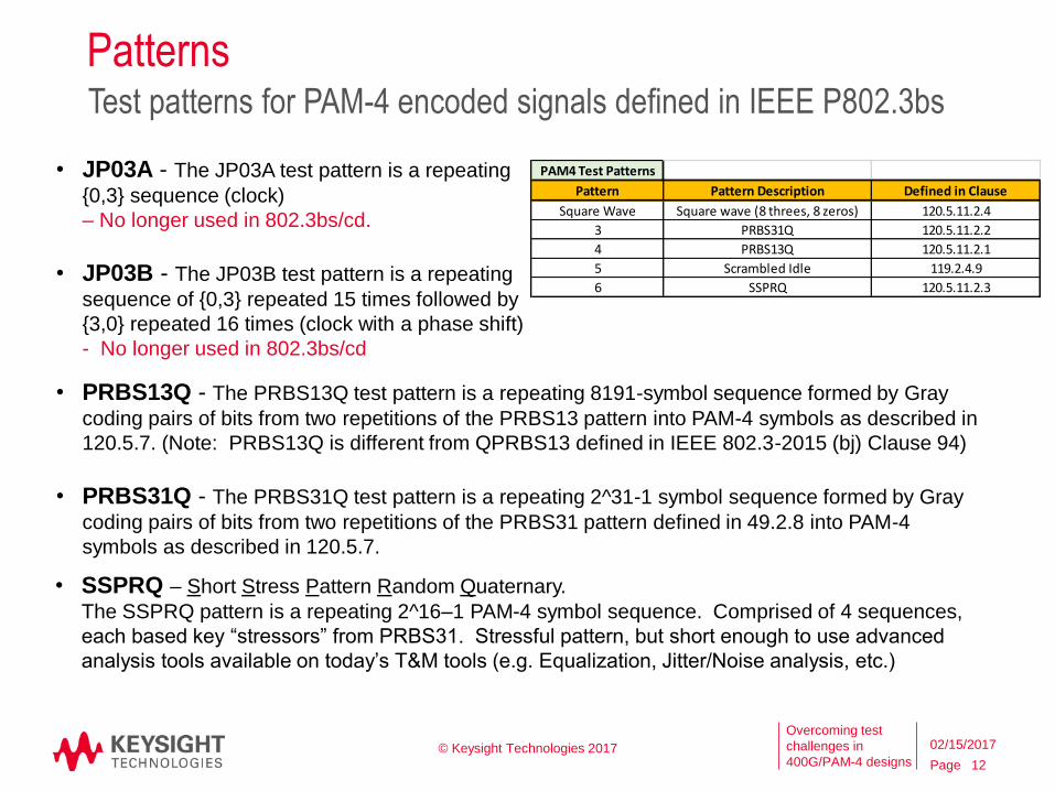
Patterns Test patterns for PAM-4 encoded signals defined in IEEE P802.3bs
• JP03A - The JP03A test pattern is a repeating
{0,3} sequence (clock)
– No longer used in 802.3bs/cd.
• JP03B - The JP03B test pattern is a repeating
sequence of {0,3} repeated 15 times followed by
{3,0} repeated 16 times (clock with a phase shift)
- No longer used in 802.3bs/cd
© Keysight Technologies 2017
12
02/15/2017
• PRBS13Q - The PRBS13Q test pattern is a repeating 8191-symbol sequence formed by Gray
coding pairs of bits from two repetitions of the PRBS13 pattern into PAM-4 symbols as described in
120.5.7. (Note: PRBS13Q is different from QPRBS13 defined in IEEE 802.3-2015 (bj) Clause 94)
• PRBS31Q - The PRBS31Q test pattern is a repeating 2^31-1 symbol sequence formed by Gray
coding pairs of bits from two repetitions of the PRBS31 pattern defined in 49.2.8 into PAM-4
symbols as described in 120.5.7.
• SSPRQ – Short Stress Pattern Random Quaternary.
The SSPRQ pattern is a repeating 2^16–1 PAM-4 symbol sequence. Comprised of 4 sequences,
each based key “stressors” from PRBS31. Stressful pattern, but short enough to use advanced
analysis tools available on today’s T&M tools (e.g. Equalization, Jitter/Noise analysis, etc.)
PAM4 Test Patterns
Pattern Pattern Description Defined in Clause
Square Wave Square wave (8 threes, 8 zeros) 120.5.11.2.4
3 PRBS31Q 120.5.11.2.2
4 PRBS13Q 120.5.11.2.1
5 Scrambled Idle 119.2.4.9
6 SSPRQ 120.5.11.2.3
Page
Overcoming test
challenges in
400G/PAM-4 designs
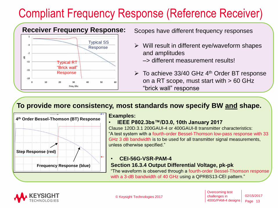
Receiver Frequency Response:
4th Order Bessel-Thomson (BT) Response
Typical RT
“Brick wall”
Response
Typical SS
Response
Scopes have different frequency responses
Will result in different eye/waveform shapes
and amplitudes
–> different measurement results!
Examples:
• IEEE P802.3bs™/D3.0, 10th January 2017Clause 120D.3.1 200GAUI-4 or 400GAUI-8 transmitter characteristics:
“A test system with a fourth-order Bessel-Thomson low-pass response with 33
GHz 3 dB bandwidth is to be used for all transmitter signal measurements,
unless otherwise specified.”
To provide more consistency, most standards now specify BW and shape.
• CEI-56G-VSR-PAM-4
Section 16.3.4 Output Differential Voltage, pk-pk“The waveform is observed through a fourth-order Bessel-Thomson response
with a 3-dB bandwidth of 40 GHz using a QPRBS13-CEI pattern.”
Compliant Frequency Response (Reference Receiver)
Step Response (red)
Frequency Response (blue)
© Keysight Technologies 2017
13
02/15/2017
To achieve 33/40 GHz 4th Order BT response
on a RT scope, must start with > 60 GHz
“brick wall” response
Page
Overcoming test
challenges in
400G/PAM-4 designs
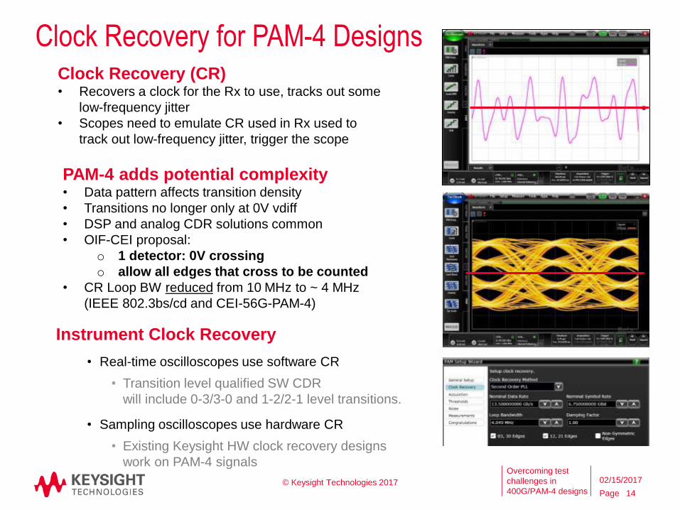
Clock Recovery for PAM-4 DesignsClock Recovery (CR)• Recovers a clock for the Rx to use, tracks out some
low-frequency jitter
• Scopes need to emulate CR used in Rx used to
track out low-frequency jitter, trigger the scope
PAM-4 adds potential complexity• Data pattern affects transition density
• Transitions no longer only at 0V vdiff
• DSP and analog CDR solutions common
• OIF-CEI proposal:
o 1 detector: 0V crossing
o allow all edges that cross to be counted
• CR Loop BW reduced from 10 MHz to ~ 4 MHz
(IEEE 802.3bs/cd and CEI-56G-PAM-4)
Instrument Clock Recovery
• Real-time oscilloscopes use software CR
• Transition level qualified SW CDR
will include 0-3/3-0 and 1-2/2-1 level transitions.
• Sampling oscilloscopes use hardware CR
• Existing Keysight HW clock recovery designs
work on PAM-4 signals
© Keysight Technologies 2017
14
02/15/2017
Output (Transmitter) Characterization: Optical
Page
Overcoming test
challenges in
400G/PAM-4 designs © Keysight Technologies 2017
16
02/15/2017
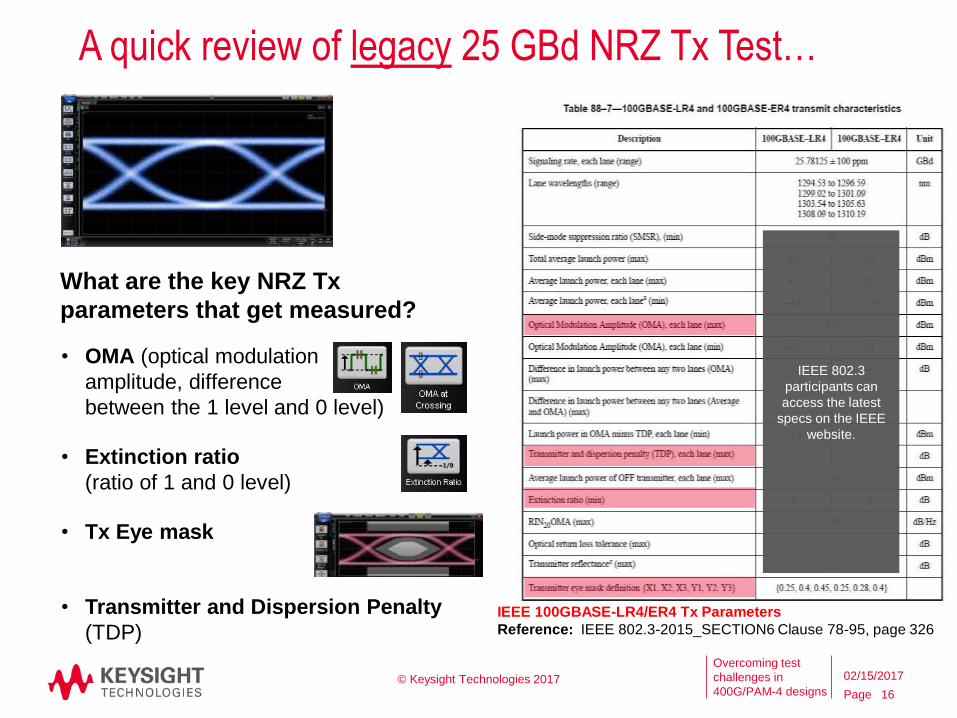
A quick review of legacy 25 GBd NRZ Tx Test…
• OMA (optical modulation
amplitude, difference
between the 1 level and 0 level)
• Extinction ratio
(ratio of 1 and 0 level)
• Tx Eye mask
• Transmitter and Dispersion Penalty
(TDP)
What are the key NRZ Tx
parameters that get measured?
IEEE 100GBASE-LR4/ER4 Tx Parameters
Reference: IEEE 802.3-2015_SECTION6 Clause 78-95, page 326
IEEE 802.3
participants can
access the latest
specs on the IEEE
website.
Page
Overcoming test
challenges in
400G/PAM-4 designs
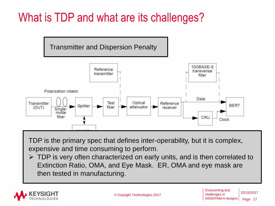
What is TDP and what are its challenges?
© Keysight Technologies 2017
17
02/15/2017
Transmitter and Dispersion Penalty
Reference: IEEE 802.3-2015_SECTION4 Clause 44-55, page 513
TDP is the primary spec that defines inter-operability, but it is complex,
expensive and time consuming to perform.
TDP is very often characterized on early units, and is then correlated to
Extinction Ratio, OMA, and Eye Mask. ER, OMA and eye mask are
then tested in manufacturing.
Page
Overcoming test
challenges in
400G/PAM-4 designs
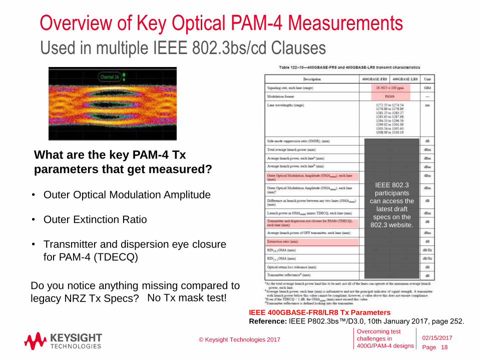
Overview of Key Optical PAM-4 MeasurementsUsed in multiple IEEE 802.3bs/cd Clauses
© Keysight Technologies 2017
18
02/15/2017
• Outer Optical Modulation Amplitude
• Outer Extinction Ratio
• Transmitter and dispersion eye closure
for PAM-4 (TDECQ)
IEEE 400GBASE-FR8/LR8 Tx Parameters
Reference: IEEE P802.3bs™/D3.0, 10th January 2017, page 252.
Do you notice anything missing compared to
legacy NRZ Tx Specs?
What are the key PAM-4 Tx
parameters that get measured?
IEEE 802.3
participants
can access the
latest draft
specs on the
802.3 website.
No Tx mask test!
Page
Overcoming test
challenges in
400G/PAM-4 designs
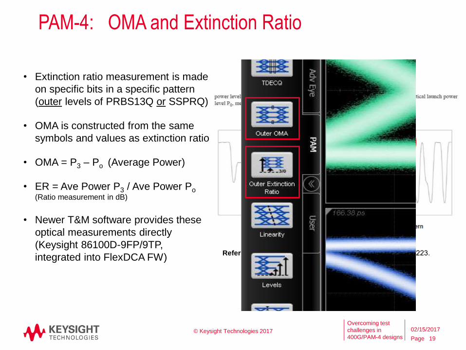
PAM-4: OMA and Extinction Ratio
• Extinction ratio measurement is made
on specific bits in a specific pattern
(outer levels of PRBS13Q or SSPRQ)
• OMA is constructed from the same
symbols and values as extinction ratio
• OMA = P3 – Po (Average Power)
• ER = Ave Power P3 / Ave Power Po(Ratio measurement in dB)
• Newer T&M software provides these
optical measurements directly
(Keysight 86100D-9FP/9TP,
integrated into FlexDCA FW)Reference: IEEE P802.3bs™/D2.1, 6th October 2016, page 223.
© Keysight Technologies 2017
19
02/15/2017
Page
Overcoming test
challenges in
400G/PAM-4 designs
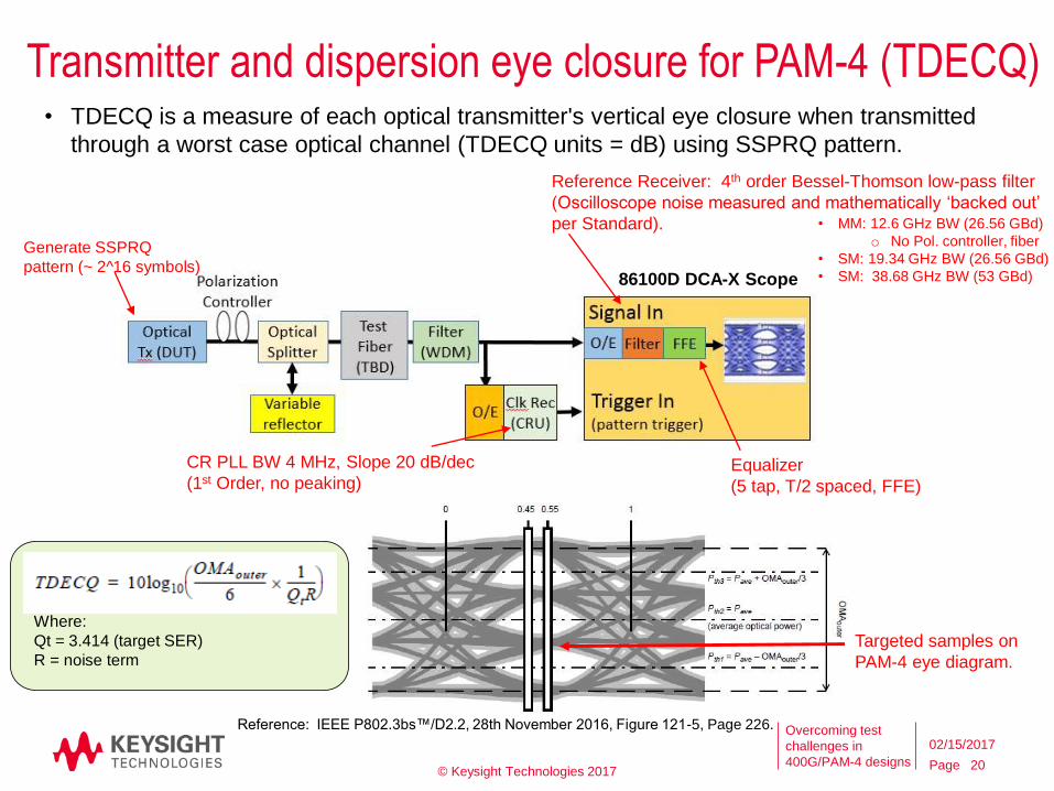
Transmitter and dispersion eye closure for PAM-4 (TDECQ)
© Keysight Technologies 201720
02/15/2017
Where:
Qt = 3.414 (target SER)
R = noise term
• TDECQ is a measure of each optical transmitter's vertical eye closure when transmitted
through a worst case optical channel (TDECQ units = dB) using SSPRQ pattern.
Equalizer
(5 tap, T/2 spaced, FFE)
Reference Receiver: 4th order Bessel-Thomson low-pass filter
(Oscilloscope noise measured and mathematically ‘backed out’
per Standard).
CR PLL BW 4 MHz, Slope 20 dB/dec
(1st Order, no peaking)
Reference: IEEE P802.3bs™/D2.2, 28th November 2016, Figure 121-5, Page 226.
86100D DCA-X Scope
Generate SSPRQ
pattern (~ 2^16 symbols)
Targeted samples on
PAM-4 eye diagram.
• MM: 12.6 GHz BW (26.56 GBd)
o No Pol. controller, fiber
• SM: 19.34 GHz BW (26.56 GBd)
• SM: 38.68 GHz BW (53 GBd)
Page
Overcoming test
challenges in
400G/PAM-4 designs
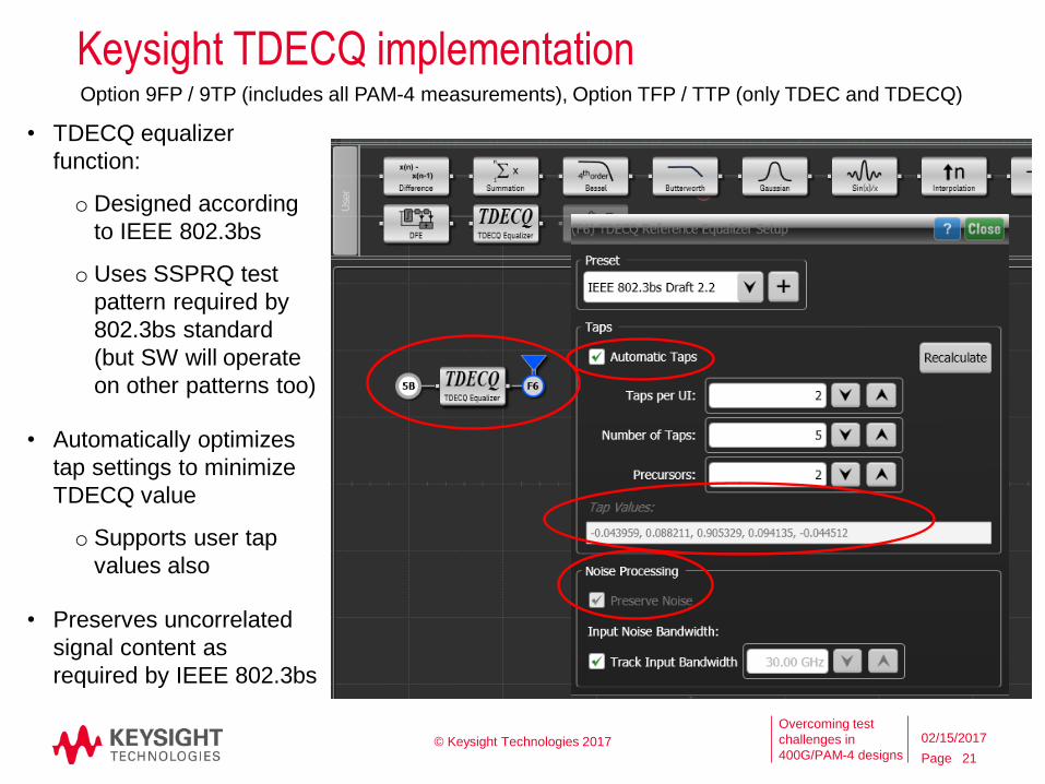
Keysight TDECQ implementation
© Keysight Technologies 2017
21
02/15/2017
Option 9FP / 9TP (includes all PAM-4 measurements), Option TFP / TTP (only TDEC and TDECQ)
• TDECQ equalizer
function:
o Designed according
to IEEE 802.3bs
o Uses SSPRQ test
pattern required by
802.3bs standard
(but SW will operate
on other patterns too)
• Automatically optimizes
tap settings to minimize
TDECQ value
o Supports user tap
values also
• Preserves uncorrelated
signal content as
required by IEEE 802.3bs
Page
Overcoming test
challenges in
400G/PAM-4 designs
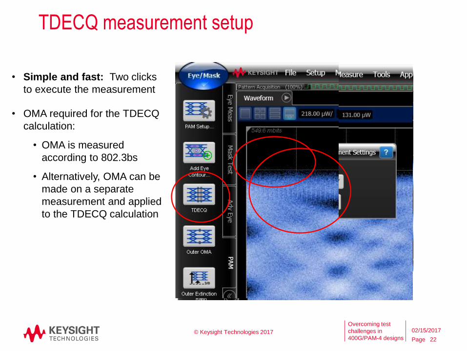
TDECQ measurement setup
• Simple and fast: Two clicks
to execute the measurement
• OMA required for the TDECQ
calculation:
• OMA is measured
according to 802.3bs
• Alternatively, OMA can be
made on a separate
measurement and applied
to the TDECQ calculation
© Keysight Technologies 2017
22
02/15/2017
Page
Overcoming test
challenges in
400G/PAM-4 designs
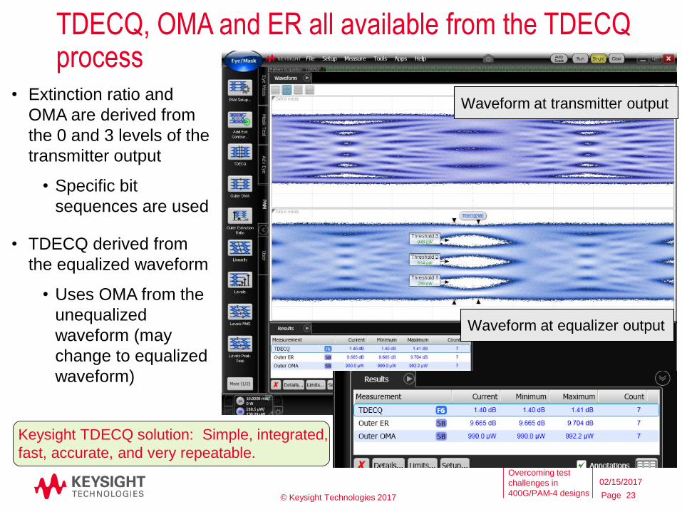
TDECQ, OMA and ER all available from the TDECQ process
• Extinction ratio and
OMA are derived from
the 0 and 3 levels of the
transmitter output
• Specific bit
sequences are used
• TDECQ derived from
the equalized waveform
• Uses OMA from the
unequalized
waveform (may
change to equalized
waveform)
Waveform at transmitter output
Waveform at equalizer output
© Keysight Technologies 2017 23
02/15/2017
Keysight TDECQ solution: Simple, integrated,
fast, accurate, and very repeatable.
Page
Overcoming test
challenges in
400G/PAM-4 designs
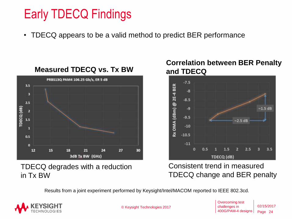
Early TDECQ Findings
© Keysight Technologies 2017
24
02/15/2017
Consistent trend in measured
TDECQ change and BER penalty
Measured TDECQ vs. Tx BW
TDECQ degrades with a reduction
in Tx BW
Correlation between BER Penalty
and TDECQ
• TDECQ appears to be a valid method to predict BER performance
Results from a joint experiment performed by Keysight/Intel/MACOM reported to IEEE 802.3cd.
Page
Overcoming test
challenges in
400G/PAM-4 designs
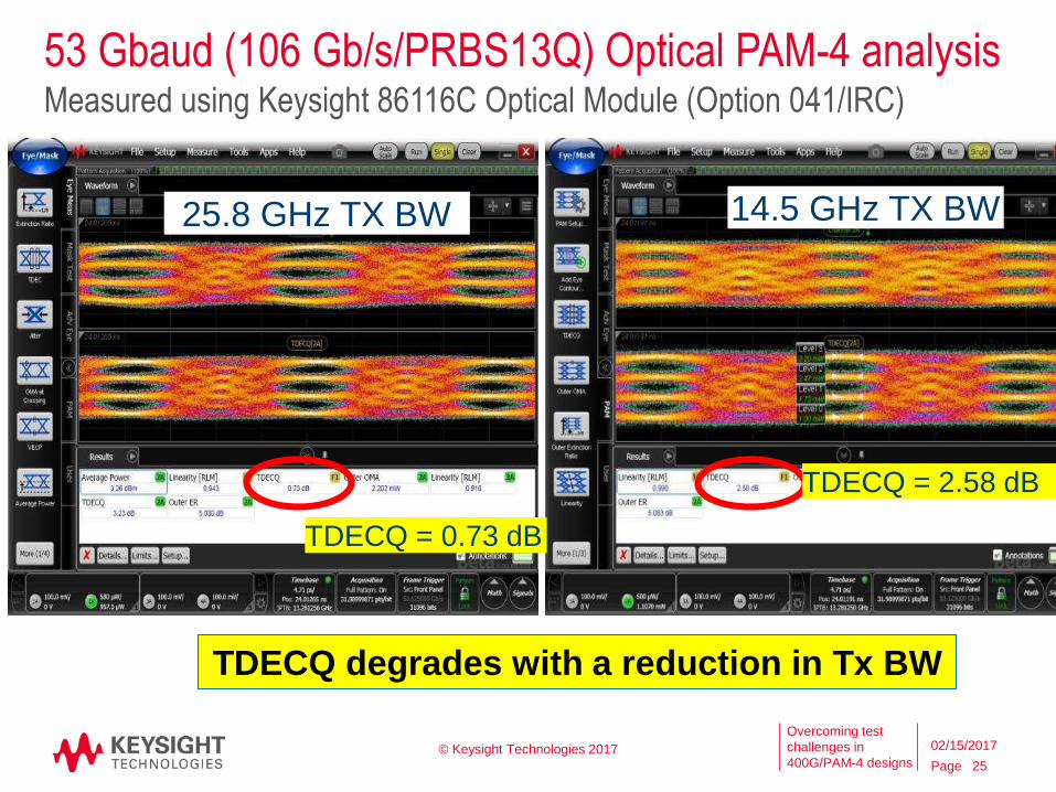
53 Gbaud (106 Gb/s/PRBS13Q) Optical PAM-4 analysis
23 GHz with FRC (-3000)
33 GHz with FRC (-3000)
© Keysight Technologies 2017
25
02/15/2017
Measured using Keysight 86116C Optical Module (Option 041/IRC)
25.8 GHz TX BW 14.5 GHz TX BW
TDECQ = 0.73 dB
TDECQ = 2.58 dB
TDECQ degrades with a reduction in Tx BW
Page
Overcoming test
challenges in
400G/PAM-4 designs © Keysight Technologies 2017
26
02/15/2017
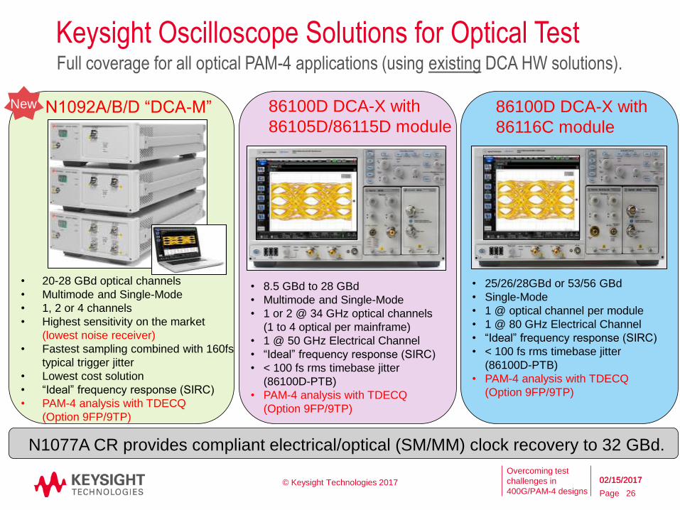
Keysight Oscilloscope Solutions for Optical TestFull coverage for all optical PAM-4 applications (using existing DCA HW solutions).
N1092A/B/D “DCA-M”
• 20-28 GBd optical channels
• Multimode and Single-Mode
• 1, 2 or 4 channels
• Highest sensitivity on the market
(lowest noise receiver)
• Fastest sampling combined with 160fs
typical trigger jitter
• Lowest cost solution
• “Ideal” frequency response (SIRC)
• PAM-4 analysis with TDECQ
(Option 9FP/9TP)
86100D DCA-X with
86105D/86115D module
86100D DCA-X with
86116C module
• 8.5 GBd to 28 GBd
• Multimode and Single-Mode
• 1 or 2 @ 34 GHz optical channels
(1 to 4 optical per mainframe)
• 1 @ 50 GHz Electrical Channel
• “Ideal” frequency response (SIRC)
• < 100 fs rms timebase jitter
(86100D-PTB)
• PAM-4 analysis with TDECQ
(Option 9FP/9TP)
• 25/26/28GBd or 53/56 GBd
• Single-Mode
• 1 @ optical channel per module
• 1 @ 80 GHz Electrical Channel
• “Ideal” frequency response (SIRC)
• < 100 fs rms timebase jitter
(86100D-PTB)
• PAM-4 analysis with TDECQ
(Option 9FP/9TP)
N1077A CR provides compliant electrical/optical (SM/MM) clock recovery to 32 GBd.
New
02/15/2017
Page
Overcoming test
challenges in
400G/PAM-4 designs
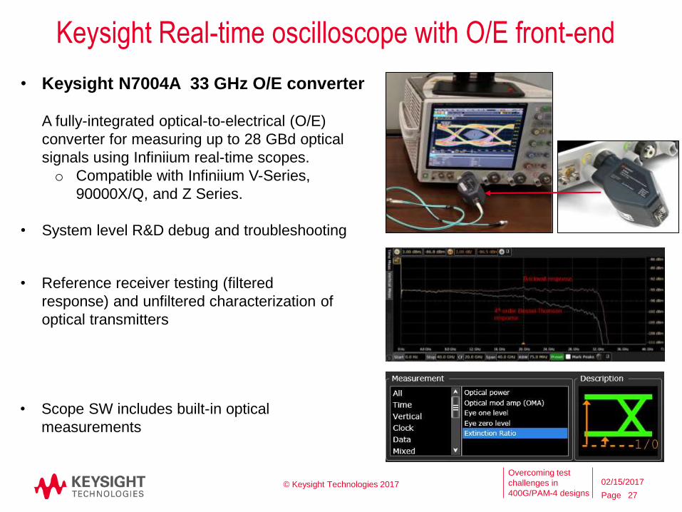
Keysight Real-time oscilloscope with O/E front-end
© Keysight Technologies 2017
27
02/15/2017
• Keysight N7004A 33 GHz O/E converter
A fully-integrated optical-to-electrical (O/E)
converter for measuring up to 28 GBd optical
signals using Infiniium real-time scopes.
o Compatible with Infiniium V-Series,
90000X/Q, and Z Series.
• System level R&D debug and troubleshooting
• Scope SW includes built-in optical
measurements
• Reference receiver testing (filtered
response) and unfiltered characterization of
optical transmitters
Output (Transmitter) Characterization: Electrical
Page
Overcoming test
challenges in
400G/PAM-4 designs
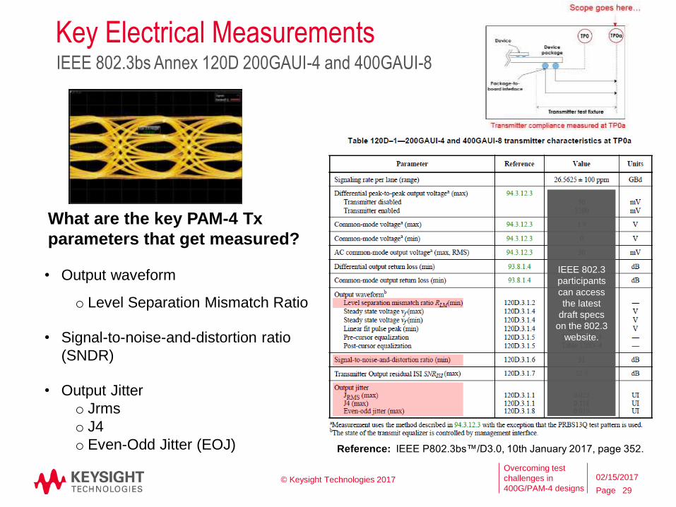
Key Electrical Measurements
© Keysight Technologies 2017
IEEE 802.3bs Annex 120D 200GAUI-4 and 400GAUI-8
29
02/15/2017
Reference: IEEE P802.3bs™/D3.0, 10th January 2017, page 352.
IEEE 802.3
participants
can access
the latest
draft specs
on the 802.3
website.
• Output waveform
o Level Separation Mismatch Ratio
• Signal-to-noise-and-distortion ratio
(SNDR)
• Output Jitter
o Jrms
o J4
o Even-Odd Jitter (EOJ)
What are the key PAM-4 Tx
parameters that get measured?
Page
Overcoming test
challenges in
400G/PAM-4 designs
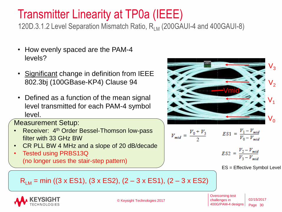
Transmitter Linearity at TP0a (IEEE)
• How evenly spaced are the PAM-4
levels?
• Significant change in definition from IEEE
802.3bj (100GBase-KP4) Clause 94
• Defined as a function of the mean signal
level transmitted for each PAM-4 symbol
level.
© Keysight Technologies 2017
120D.3.1.2 Level Separation Mismatch Ratio, RLM (200GAUI-4 and 400GAUI-8)
30
02/15/2017
RLM = min ((3 x ES1), (3 x ES2), (2 – 3 x ES1), (2 – 3 x ES2)
V0
V1
V2
V3
Vmid
Measurement Setup:• Receiver: 4th Order Bessel-Thomson low-pass
filter with 33 GHz BW
• CR PLL BW 4 MHz and a slope of 20 dB/decade
• Tested using PRBS13Q
(no longer uses the stair-step pattern)ES = Effective Symbol Level
Page
Overcoming test
challenges in
400G/PAM-4 designs © Keysight Technologies 2017 31
02/15/2017
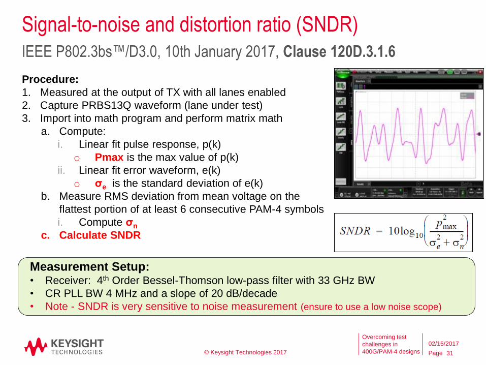
Signal-to-noise and distortion ratio (SNDR)
Procedure:
1. Measured at the output of TX with all lanes enabled
2. Capture PRBS13Q waveform (lane under test)
3. Import into math program and perform matrix math
a. Compute:
i. Linear fit pulse response, p(k)
o Pmax is the max value of p(k)
ii. Linear fit error waveform, e(k)
o σe is the standard deviation of e(k)
b. Measure RMS deviation from mean voltage on the
flattest portion of at least 6 consecutive PAM-4 symbols
i. Compute σn
c. Calculate SNDR
IEEE P802.3bs™/D3.0, 10th January 2017, Clause 120D.3.1.6
Measurement Setup:• Receiver: 4th Order Bessel-Thomson low-pass filter with 33 GHz BW
• CR PLL BW 4 MHz and a slope of 20 dB/decade
• Note - SNDR is very sensitive to noise measurement (ensure to use a low noise scope)
Page
Overcoming test
challenges in
400G/PAM-4 designs
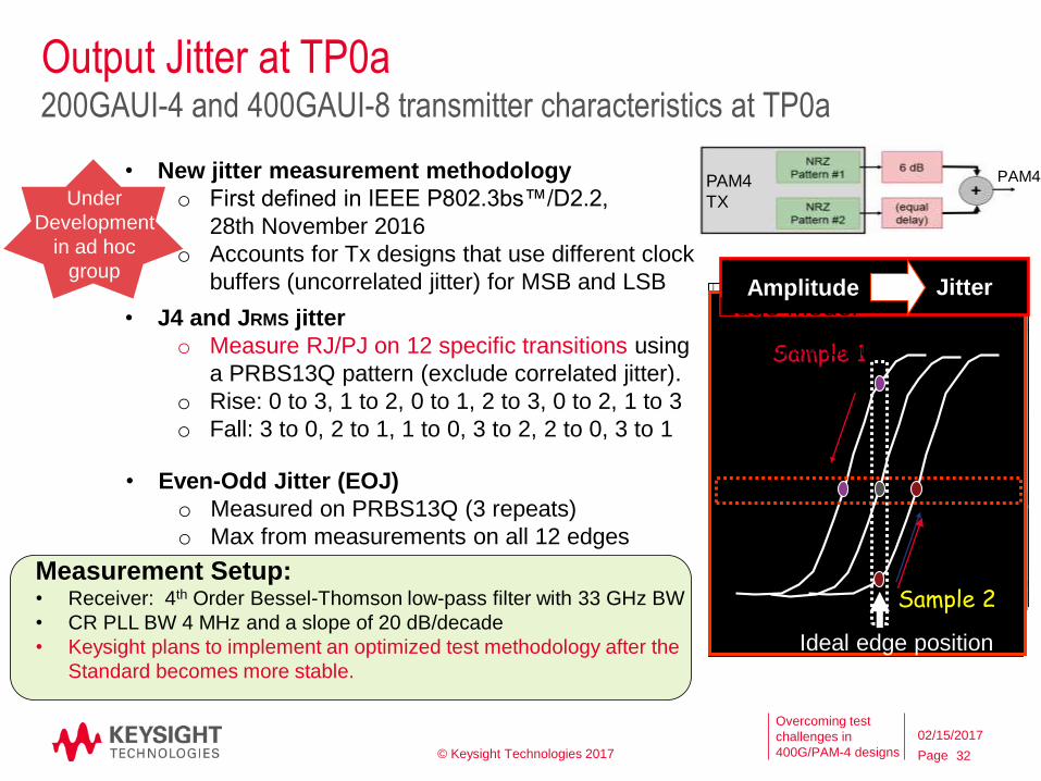
Sample 1
Sample 2
Amplitude Jitter
© Keysight Technologies 2017 32
02/15/2017
Output Jitter at TP0a200GAUI-4 and 400GAUI-8 transmitter characteristics at TP0a
Measurement Setup:• Receiver: 4th Order Bessel-Thomson low-pass filter with 33 GHz BW
• CR PLL BW 4 MHz and a slope of 20 dB/decade
• Keysight plans to implement an optimized test methodology after the
Standard becomes more stable.
• New jitter measurement methodology
o First defined in IEEE P802.3bs™/D2.2,
28th November 2016
o Accounts for Tx designs that use different clock
buffers (uncorrelated jitter) for MSB and LSB
• J4 and JRMS jitter
o Measure RJ/PJ on 12 specific transitions using
a PRBS13Q pattern (exclude correlated jitter).
o Rise: 0 to 3, 1 to 2, 0 to 1, 2 to 3, 0 to 2, 1 to 3
o Fall: 3 to 0, 2 to 1, 1 to 0, 3 to 2, 2 to 0, 3 to 1
• Even-Odd Jitter (EOJ)
o Measured on PRBS13Q (3 repeats)
o Max from measurements on all 12 edges
Under
Development
in ad hoc
group
PAM4
TX
Edge ModelAmplitude-to-Time
(Jitter) transfer function
~ 100% efficiency
PAM4
Ideal edge position
Page
Overcoming test
challenges in
400G/PAM-4 designs
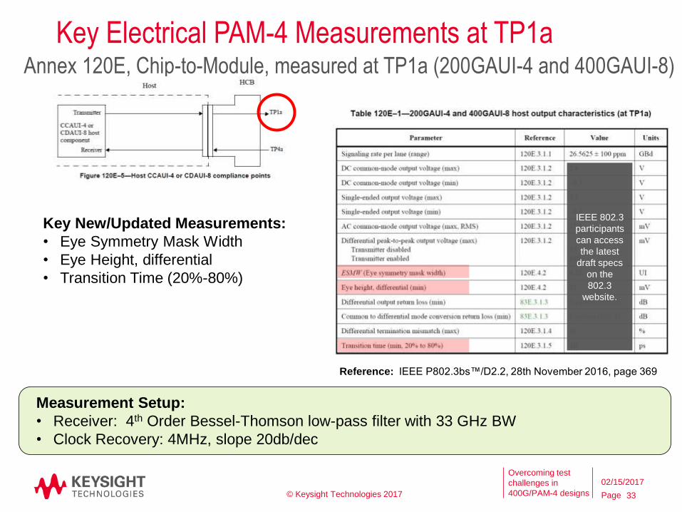
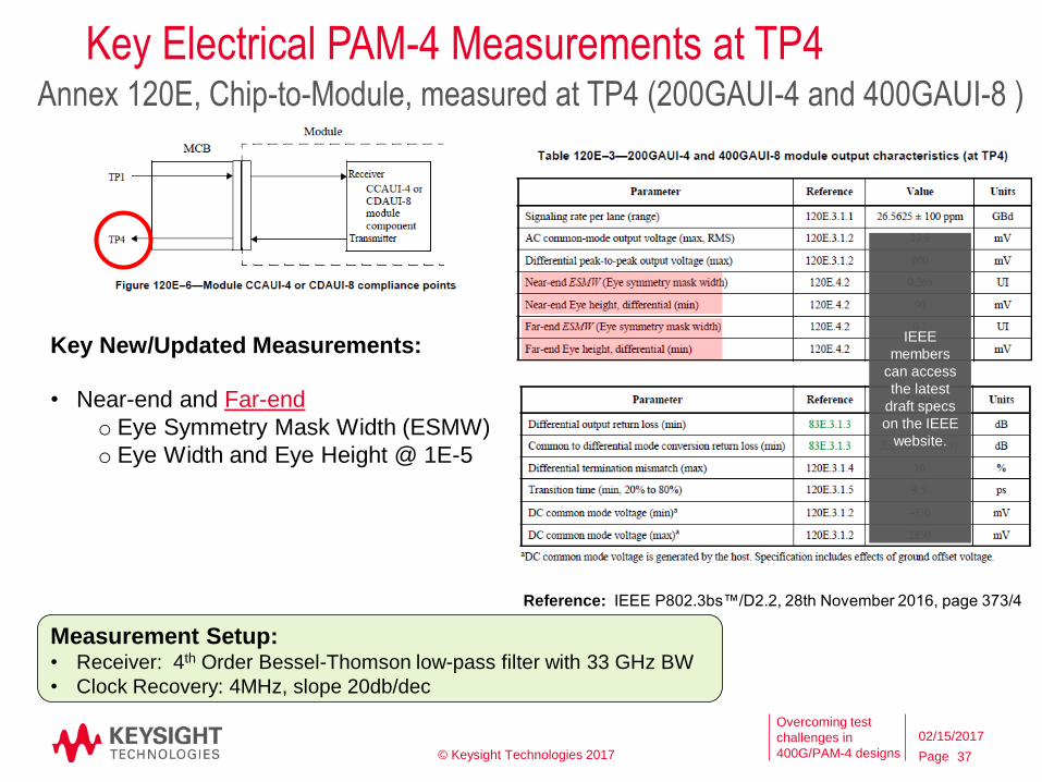
Key Electrical PAM-4 Measurements at TP1a
Key New/Updated Measurements:
• Eye Symmetry Mask Width
• Eye Height, differential
• Transition Time (20%-80%)
Annex 120E, Chip-to-Module, measured at TP1a (200GAUI-4 and 400GAUI-8)
Measurement Setup:
• Receiver: 4th Order Bessel-Thomson low-pass filter with 33 GHz BW
• Clock Recovery: 4MHz, slope 20db/dec
Reference: IEEE P802.3bs™/D2.2, 28th November 2016, page 369
© Keysight Technologies 2017 33
02/15/2017
IEEE 802.3
participants
can access
the latest
draft specs
on the
802.3
website.
Page
Overcoming test
challenges in
400G/PAM-4 designs
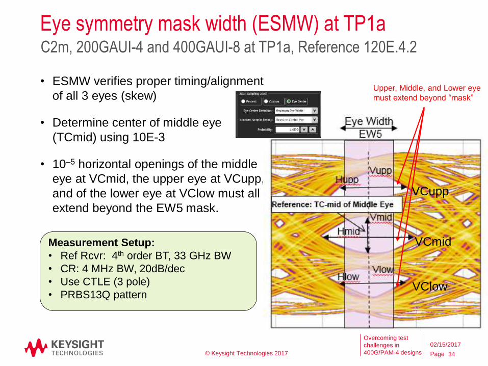
Eye symmetry mask width (ESMW) at TP1a
• ESMW verifies proper timing/alignment
of all 3 eyes (skew)
• Determine center of middle eye
(TCmid) using 10E-3
• 10–5 horizontal openings of the middle
eye at VCmid, the upper eye at VCupp,
and of the lower eye at VClow must all
extend beyond the EW5 mask.
C2m, 200GAUI-4 and 400GAUI-8 at TP1a, Reference 120E.4.2
Upper, Middle, and Lower eye
must extend beyond “mask”
Measurement Setup:
• Ref Rcvr: 4th order BT, 33 GHz BW
• CR: 4 MHz BW, 20dB/dec
• Use CTLE (3 pole)
• PRBS13Q pattern
VCmid
VCupp
VClow
© Keysight Technologies 2017 34
02/15/2017
Page
Overcoming test
challenges in
400G/PAM-4 designs
Host output eye height (TP1a)
120E.3.1.6 Host output eye width and eye height
• Measure EW of all 3 PAM-4 eyes @ 1E-5
using methodology outlined in 120E.4.2
C2m, 200GAUI-4 and 400GAUI-8 at TP1a, EW Reference 120E.4.2
Measurement Setup:
• Ref Rcvr: 4th order BT, 33 GHz BW
• CR: 4 MHz BW, 20dB/dec
• Use CTLE (3 pole) defined in 120E.3.1.7
• PRBS13Q pattern
© Keysight Technologies 2017 35
02/15/2017
Page
Overcoming test
challenges in
400G/PAM-4 designs
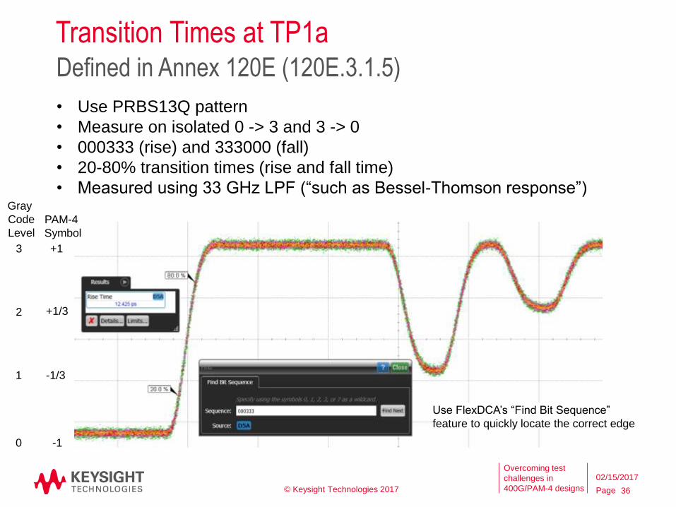
Transition Times at TP1aDefined in Annex 120E (120E.3.1.5)
• Use PRBS13Q pattern
• Measure on isolated 0 -> 3 and 3 -> 0
• 000333 (rise) and 333000 (fall)
• 20-80% transition times (rise and fall time)
• Measured using 33 GHz LPF (“such as Bessel-Thomson response”)
Use FlexDCA’s “Find Bit Sequence”
feature to quickly locate the correct edge
-1/3
-1
+1/3
+1
1
0
2
3
Gray
Code
Level
PAM-4
Symbol
© Keysight Technologies 2017 36
02/15/2017
Page
Overcoming test
challenges in
400G/PAM-4 designs
Key Electrical PAM-4 Measurements at TP4
Key New/Updated Measurements:
• Near-end and Far-end
o Eye Symmetry Mask Width (ESMW)
o Eye Width and Eye Height @ 1E-5
Annex 120E, Chip-to-Module, measured at TP4 (200GAUI-4 and 400GAUI-8 )
Measurement Setup:• Receiver: 4th Order Bessel-Thomson low-pass filter with 33 GHz BW
• Clock Recovery: 4MHz, slope 20db/dec
Reference: IEEE P802.3bs™/D2.2, 28th November 2016, page 373/4
© Keysight Technologies 2017 37
02/15/2017
IEEE
members
can access
the latest
draft specs
on the IEEE
website.
Page
Overcoming test
challenges in
400G/PAM-4 designs
Host output eye width and eye height (TP4)
120E.3.2.1 Module output eye width and eye height
• Measure EW/EH of all 3 PAM-4 eyes @ 1E-5
using methodology outlined in 120E.4.2
o Measure Near-end EW5/EH5 (with Max 3dB CTLE peaking)
o Measure Far-end after convolving with loss channel
(~ 6.4 dB loss at Nyquist defined in 92.10.7.1.1,
use any CTLE per Table 120E-2 (max 9dB)
Hmid
Vmid
HuppVupp
HlowVlow
Reference:
Center of Middle Eye
CTLE
Calculate
EW5/EH5
spec herePost process
Measure here (TP4)
• Measurement Setup:
o Reference Rcvr: 4th order BT, 33 GHz BW
o CR: 4 MHz BW, 20dB/dec
o Use CTLE (3 pole)
defined in 120E.3.1.7
o PRBS13Q pattern Loss channel
© Keysight Technologies 2017 38
02/15/2017
Input
(TP4)
Page
Overcoming test
challenges in
400G/PAM-4 designs
CEI-56G-VSR-PAM-4 Very Short Reach (VSR) InterfaceWorking draft dated June 3, 2016
Overview:
• 56 Gb/s chip-to-module PAM-4 electrical
interface (18.0 to 29.0 Gsym/s)
• Up to 10.0 dB loss at the Nyquist
frequency, including one connector.
• Drives 100 mm (min) of host PCB trace
plus one connector and 50 mm (min) of
module PCB trace.
• Raw BER of 1E-6 per lane; FEC
corrects to 1E-15 or better.
CEI-56G has similar PAM-4
measurements and methodologies
to those defined in IEEE 802.3bs.
Examples include:
• Eye Width (1E-6)
• Eye Height (1E-6)
• SNDR
• Transition Times
• Eye Symmetry Mask Width
• Eye Linearity (2 methods)
© Keysight Technologies 2017 39
02/15/2017
Page
Overcoming test
challenges in
400G/PAM-4 designs
16.3.10.1 Eye Width and Eye Height test at TP1A, TP4
• Xtalk required on all co-/counter-propagating lanes;
use QPRBS13-CEI, or QPRBS31-CEI, or a
valid CEI signal.
• Test Pattern = QPRBS13-CEI
• CRU = 1st order with fb/6640 3dB BW (same as IEEE 802.3bs) e.g. 26.56 GBd/6640 = 4 MHz
• Apply Reference CTLE
• Near-end EW6, EH6(CTLE TP1a max 9 dB, TP4 max 2 dB)
• Far-end EW6, EH6 – convolves emulated test
channel, ~7 dB loss at fb/2 (CTLE max 9 dB)
EW6 and EH6 for Host and Module output
Figure 16-7: TP1a and TP4 Eye Width, Eye Height
and Eye Amplitude
Reference: Working draft of oif2014.230.09, dated
Nov 18, 2016, page 16.
• Reference Point for all EW6/EH6:
Tmid = the midpoint of the maximum horizontal
eye opening of the 1E-3 inner eye contour of
the middle eye
© Keysight Technologies 2017 40
02/15/2017
Page
Overcoming test
challenges in
400G/PAM-4 designs
• Transmitter Linearity – defined as a function of the mean signal level
transmitted for each PAM-4 symbol (CEI-56G-VSR-PAM-4 Appendix 16.C.4.3)
• Same equation as that used in IEEE P802.3bs™/D2.2, 28th November 2016
(Refer to Level Separation Mismatch Ratio, RLM)
• Used in other CEI Clauses (not VSR-PAM-4)
• RLM = min((3 x ES1), (3 x ES2), (2 - 3 x ES1), (2 - 3 x ES2))
Transmitter Linearity
• Eye Linearity (Section 16.C.4.2)
– ratio of min to max PAM-4 eye amplitudes
• Used at TP1A and TP4
• Eye linearity = min(AVupp, AVmid, AVlow)
max(AVupp, AVmid, AVlow)
Two Methods defined in CEI-56G-VSR-PAM-4, Nov 18, 2016
Reference: Working draft of oif2014.230.09, Nov 18, 2016, page 32.
ES = Effective Symbol Level
Reference: Figure 16-7 from oif2014.230.09,
dated Nov 18, 2016, page 16.
© Keysight Technologies 2017 41
02/15/2017
Page
Overcoming test
challenges in
400G/PAM-4 designs
Keysight Electrical SolutionsUsed to characterize/troubleshoot PAM-4 Electrical Tx Designs
42
02/15/2017© Keysight Technologies 2017
Page
Overcoming test
challenges in
400G/PAM-4 designs
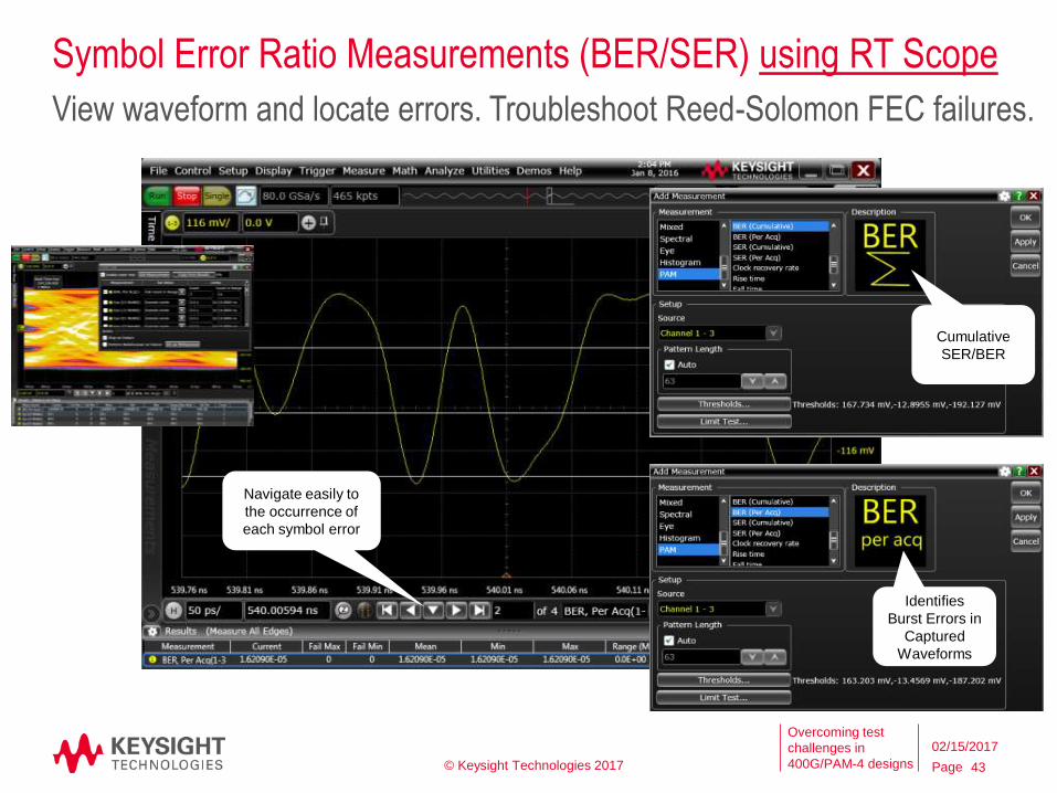
Symbol Error Ratio Measurements (BER/SER) using RT Scope
Navigate easily to
the occurrence of
each symbol error
View waveform and locate errors. Troubleshoot Reed-Solomon FEC failures.
Cumulative
SER/BER
Identifies
Burst Errors in
Captured
Waveforms
© Keysight Technologies 2017 43
02/15/2017
Page
Overcoming test
challenges in
400G/PAM-4 designs
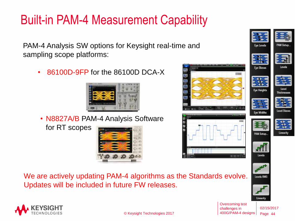
PAM-4 Analysis SW options for Keysight real-time and
sampling scope platforms:
• 86100D-9FP for the 86100D DCA-X
Built-in PAM-4 Measurement Capability
We are actively updating PAM-4 algorithms as the Standards evolve.
Updates will be included in future FW releases.
• N8827A/B PAM-4 Analysis Software
for RT scopes
© Keysight Technologies 2017 44
02/15/2017
Page
Overcoming test
challenges in
400G/PAM-4 designs
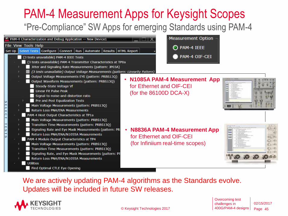
PAM-4 Measurement Apps for Keysight Scopes“Pre-Compliance” SW Apps for emerging Standards using PAM-4
• N1085A PAM-4 Measurement App
for Ethernet and OIF-CEI
(for the 86100D DCA-X)
• N8836A PAM-4 Measurement App
for Ethernet and OIF-CEI
(for Infiniium real-time scopes)
We are actively updating PAM-4 algorithms as the Standards evolve.
Updates will be included in future SW releases.
© Keysight Technologies 2017 45
02/15/2017
Page
Overcoming test
challenges in
400G/PAM-4 designs
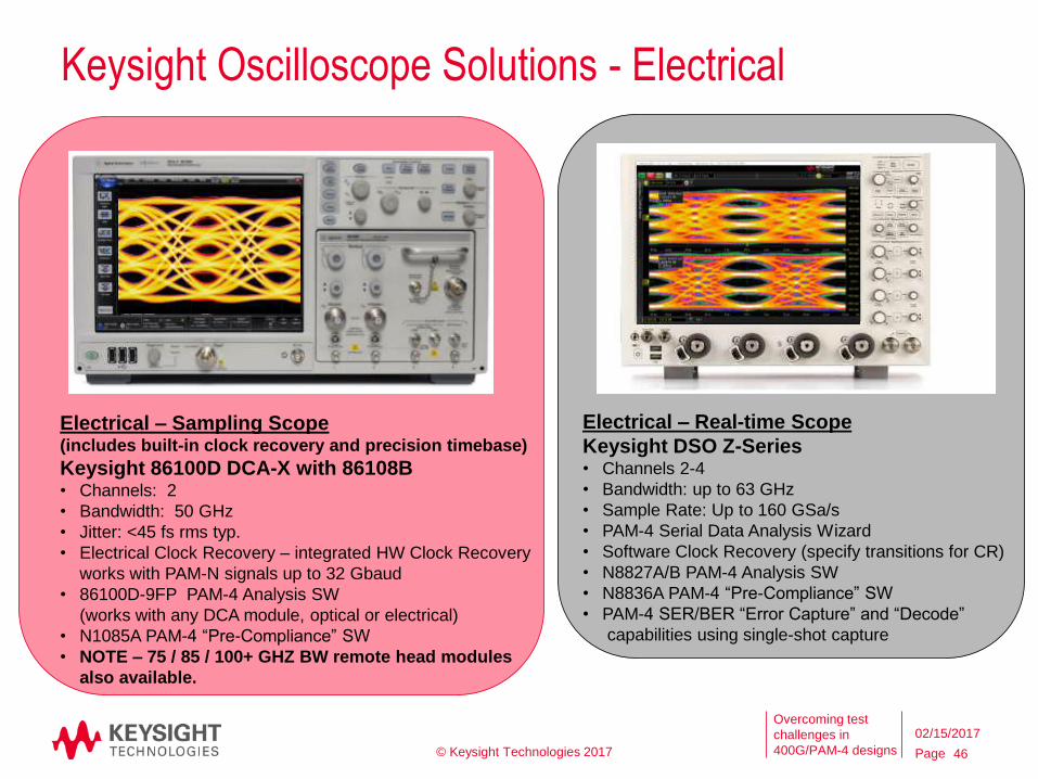
Keysight Oscilloscope Solutions - Electrical
Electrical – Sampling Scope(includes built-in clock recovery and precision timebase)
Keysight 86100D DCA-X with 86108B• Channels: 2
• Bandwidth: 50 GHz
• Jitter: <45 fs rms typ.
• Electrical Clock Recovery – integrated HW Clock Recovery
works with PAM-N signals up to 32 Gbaud
• 86100D-9FP PAM-4 Analysis SW
(works with any DCA module, optical or electrical)
• N1085A PAM-4 “Pre-Compliance” SW
• NOTE – 75 / 85 / 100+ GHZ BW remote head modules
also available.
Electrical – Real-time Scope
Keysight DSO Z-Series• Channels 2-4
• Bandwidth: up to 63 GHz
• Sample Rate: Up to 160 GSa/s
• PAM-4 Serial Data Analysis Wizard
• Software Clock Recovery (specify transitions for CR)
• N8827A/B PAM-4 Analysis SW
• N8836A PAM-4 “Pre-Compliance” SW
• PAM-4 SER/BER “Error Capture” and “Decode”
capabilities using single-shot capture
© Keysight Technologies 2017 46
02/15/2017
Page
Overcoming test
challenges in
400G/PAM-4 designs
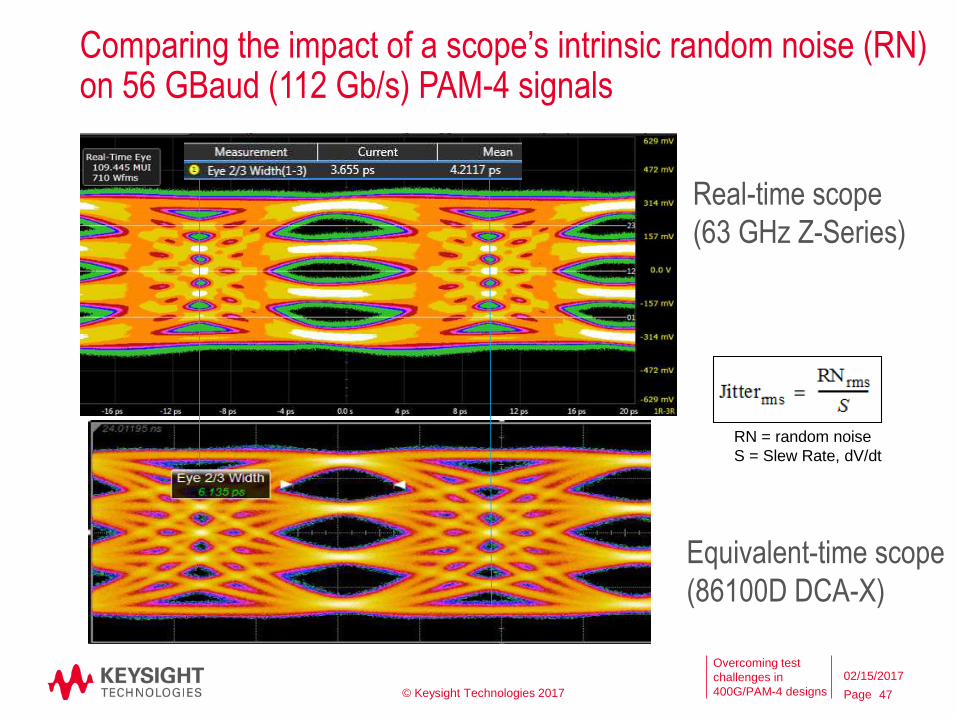
Comparing the impact of a scope’s intrinsic random noise (RN) on 56 GBaud (112 Gb/s) PAM-4 signals
Real-time scope
(63 GHz Z-Series)
Equivalent-time scope
(86100D DCA-X)
RN = random noise
S = Slew Rate, dV/dt
© Keysight Technologies 2017 47
02/15/2017
Page
Overcoming test
challenges in
400G/PAM-4 designs
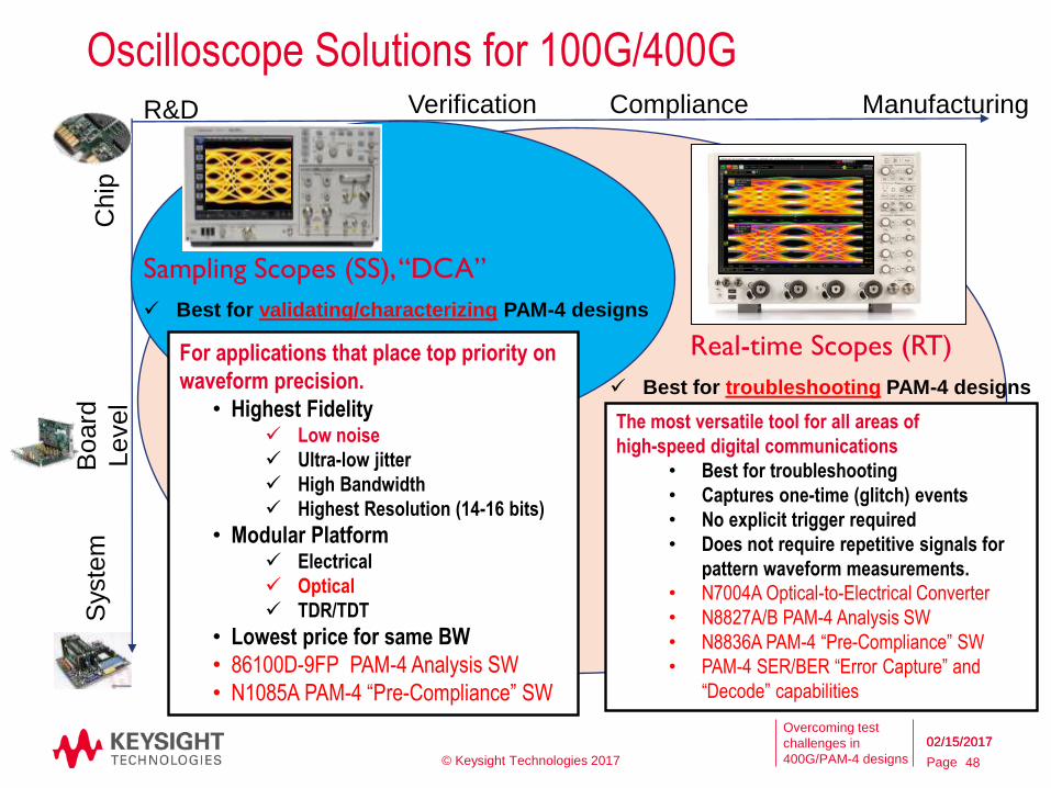
Oscilloscope Solutions for 100G/400GVerification Compliance Manufacturing
Chip
Board
Level
Syste
mR&D
Sampling Scopes (SS), “DCA”
Best for validating/characterizing PAM-4 designs
Real-time Scopes (RT)
Best for troubleshooting PAM-4 designs
The most versatile tool for all areas of
high-speed digital communications
• Best for troubleshooting
• Captures one-time (glitch) events
• No explicit trigger required
• Does not require repetitive signals for
pattern waveform measurements.
• N7004A Optical-to-Electrical Converter
• N8827A/B PAM-4 Analysis SW
• N8836A PAM-4 “Pre-Compliance” SW
• PAM-4 SER/BER “Error Capture” and
“Decode” capabilities
For applications that place top priority on
waveform precision.
• Highest Fidelity Low noise
Ultra-low jitter
High Bandwidth
Highest Resolution (14-16 bits)
• Modular Platform Electrical
Optical
TDR/TDT
• Lowest price for same BW
• 86100D-9FP PAM-4 Analysis SW
• N1085A PAM-4 “Pre-Compliance” SW
© Keysight Technologies 2017 48
02/15/201702/15/2017
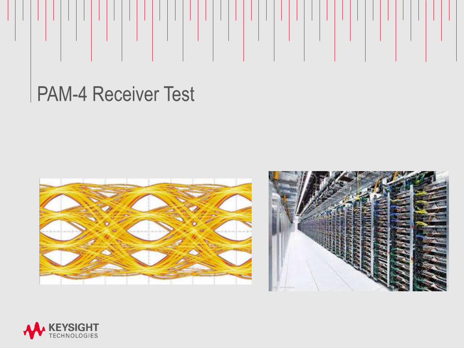
PAM-4 Receiver Test
Page
Overcoming test
challenges in
400G/PAM-4 designs
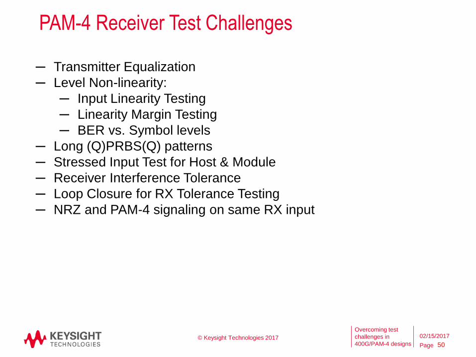
PAM-4 Receiver Test Challenges
50© Keysight Technologies 2017
─ Transmitter Equalization
─ Level Non-linearity:
─ Input Linearity Testing
─ Linearity Margin Testing
─ BER vs. Symbol levels
─ Long (Q)PRBS(Q) patterns
─ Stressed Input Test for Host & Module
─ Receiver Interference Tolerance
─ Loop Closure for RX Tolerance Testing
─ NRZ and PAM-4 signaling on same RX input
02/15/2017
Page
Overcoming test
challenges in
400G/PAM-4 designs
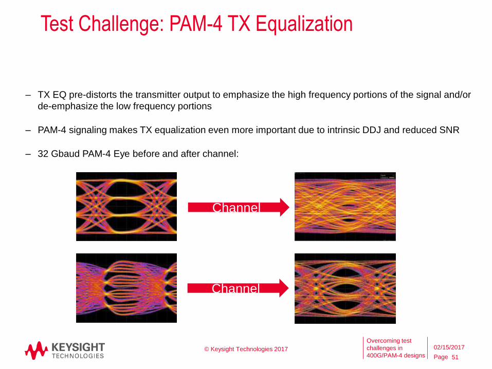
Test Challenge: PAM-4 TX Equalization
51
© Keysight Technologies 2017
– TX EQ pre-distorts the transmitter output to emphasize the high frequency portions of the signal and/or
de-emphasize the low frequency portions
– PAM-4 signaling makes TX equalization even more important due to intrinsic DDJ and reduced SNR
– 32 Gbaud PAM-4 Eye before and after channel:
Channel
Channel
02/15/2017
Page
Overcoming test
challenges in
400G/PAM-4 designs
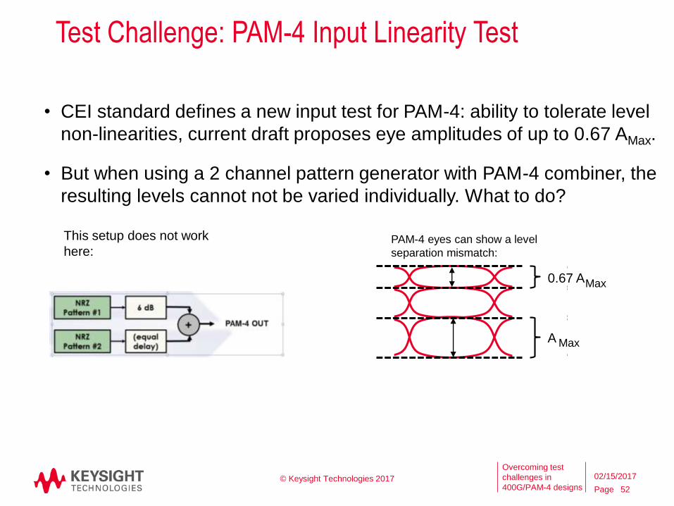
Test Challenge: PAM-4 Input Linearity Test
• CEI standard defines a new input test for PAM-4: ability to tolerate level
non-linearities, current draft proposes eye amplitudes of up to 0.67 AMax.
• But when using a 2 channel pattern generator with PAM-4 combiner, the
resulting levels cannot not be varied individually. What to do?
52
© Keysight Technologies 2017
PAM-4 eyes can show a level
separation mismatch:
0.67 AMax
A Max
This setup does not work
here:
02/15/2017
Page
Overcoming test
challenges in
400G/PAM-4 designs
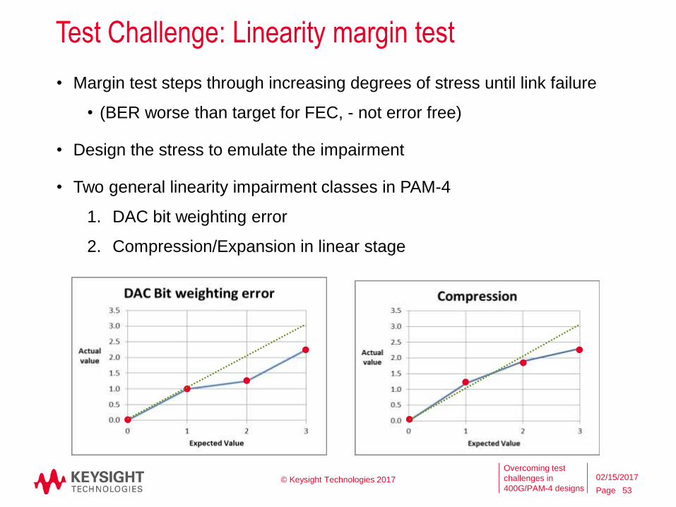
Test Challenge: Linearity margin test
• Margin test steps through increasing degrees of stress until link failure
• (BER worse than target for FEC, - not error free)
• Design the stress to emulate the impairment
• Two general linearity impairment classes in PAM-4
1. DAC bit weighting error
2. Compression/Expansion in linear stage
53
© Keysight Technologies 2017 02/15/2017
Page
Overcoming test
challenges in
400G/PAM-4 designs
Test Challenge: BER vs Symbol Level
• Receiver circuits can exhibit non-linearity effects similar to TX effects
• Understanding the BER vs. Symbol level performance of the receiver is
important
• Varying PG TX signal levels to compensate for these RX effects can
reduce the time to debug link BER issues
54
© Keysight Technologies 2017 02/15/2017
Page
Overcoming test
challenges in
400G/PAM-4 designs
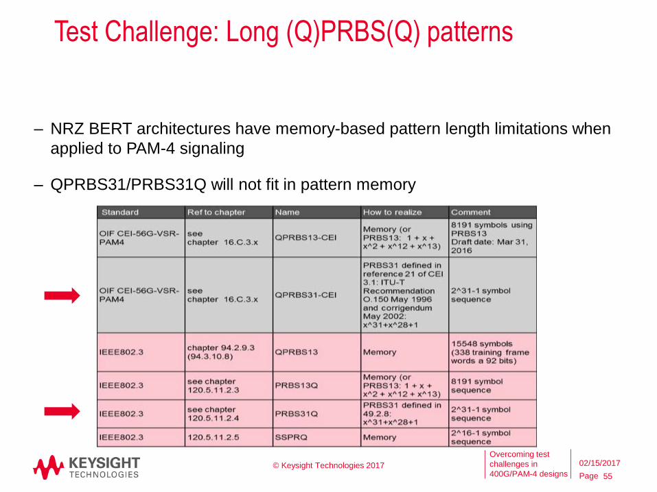
Test Challenge: Long (Q)PRBS(Q) patterns
55
– NRZ BERT architectures have memory-based pattern length limitations when
applied to PAM-4 signaling
– QPRBS31/PRBS31Q will not fit in pattern memory
© Keysight Technologies 2017 02/15/2017
Page
Overcoming test
challenges in
400G/PAM-4 designs
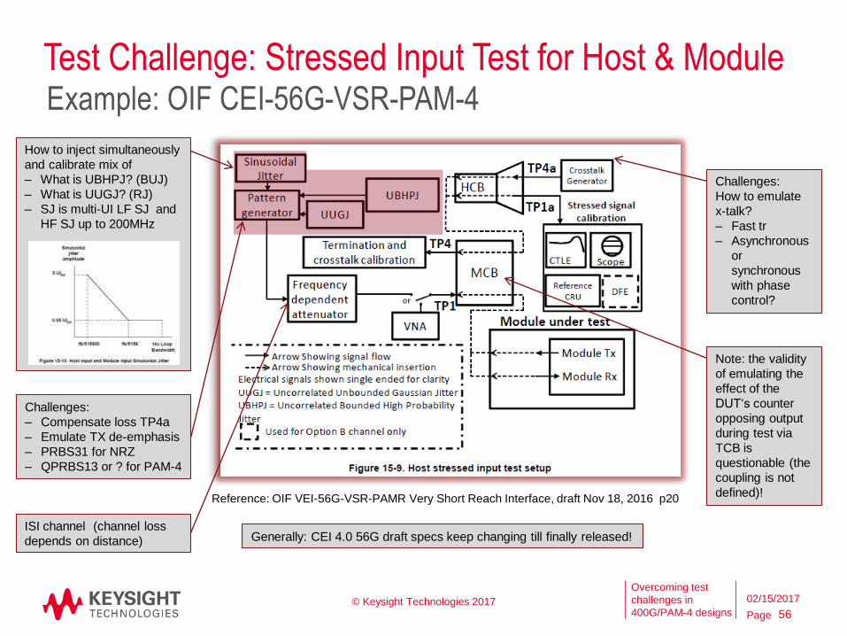
Test Challenge: Stressed Input Test for Host & Module
56
Example: OIF CEI-56G-VSR-PAM-4
Challenges:
‒ Compensate loss TP4a
‒ Emulate TX de-emphasis
‒ PRBS31 for NRZ
‒ QPRBS13 or ? for PAM-4
How to inject simultaneously
and calibrate mix of
‒ What is UBHPJ? (BUJ)
‒ What is UUGJ? (RJ)
‒ SJ is multi-UI LF SJ and
HF SJ up to 200MHz
Generally: CEI 4.0 56G draft specs keep changing till finally released!
Note: the validity
of emulating the
effect of the
DUT‘s counter
opposing output
during test via
TCB is
questionable (the
coupling is not
defined)!
Challenges:
How to emulate
x-talk?
‒ Fast tr
‒ Asynchronous
or
synchronous
with phase
control?
ISI channel (channel loss
depends on distance)
© Keysight Technologies 2017
Reference: OIF VEI-56G-VSR-PAMR Very Short Reach Interface, draft Nov 18, 2016 p20
02/15/2017
Page
Overcoming test
challenges in
400G/PAM-4 designs
The ISI channel emulates the frequency
dependent loss of a backplane channel.
Test Challenge: Receiver Interference Tolerance
57
COM Method referenced by OIF CEI-56G-LR/MR-PAM-4 (draft)
Challenge: the transmitter output, as measured
at TP0a, meets all transmitter specifications:
• Pre- and post- cursor peaking ratio
as of CEI-56G-LR-PAM-4
The Channel Operating Margin (COM) is a figure of merit for a channel derived from a measurement of its
scattering parameters. COM is related to the ratio of a calculated signal amplitude to a calculated noise amplitude =
20log10(As/Ani). Source: IEEE 802.3bj™-2014, Annex 93A
The channel noise
source emulates
crosstalk and non-
equalize-able signal
distortions introduced
by a channel.
It is Gaussian with a
crest factor of at least
4.
Challenge:
Differential
adders cause
loss +skew
+reflections.
Challenge: get all data needed for MATLAB
COM model input file to calculate desired eye
height correctly.
0.1- 0.5
© Keysight Technologies 2017
Reference: IEEE 802.3-2015
Annex 93C – Figure 93C-2
Interference tolerance test
setup
02/15/2017
Page
Overcoming test
challenges in
400G/PAM-4 designs
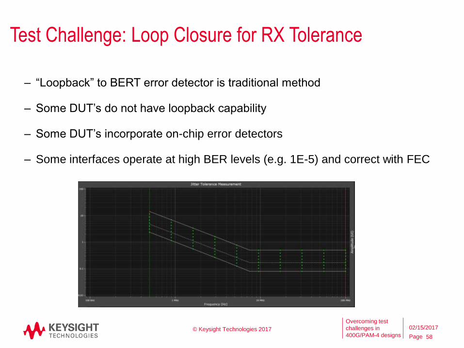
Test Challenge: Loop Closure for RX Tolerance
58
– “Loopback” to BERT error detector is traditional method
– Some DUT’s do not have loopback capability
– Some DUT’s incorporate on-chip error detectors
– Some interfaces operate at high BER levels (e.g. 1E-5) and correct with FEC
© Keysight Technologies 2017 02/15/2017
Page
Overcoming test
challenges in
400G/PAM-4 designs
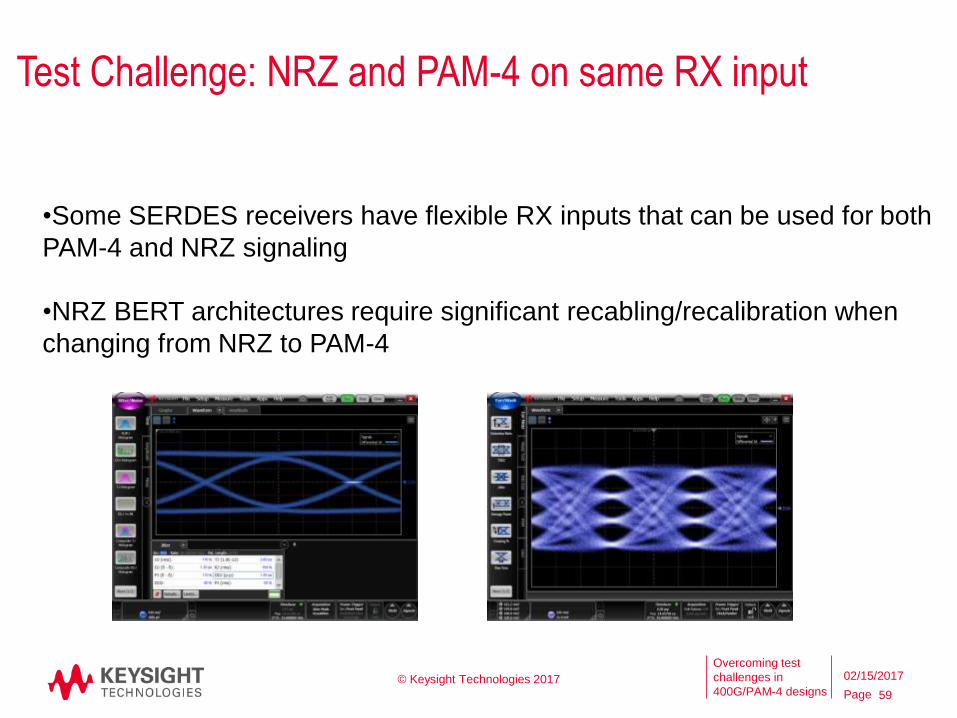
Test Challenge: NRZ and PAM-4 on same RX input
59
© Keysight Technologies 2017
•Some SERDES receivers have flexible RX inputs that can be used for both
PAM-4 and NRZ signaling
•NRZ BERT architectures require significant recabling/recalibration when
changing from NRZ to PAM-4
02/15/2017
Page
Overcoming test
challenges in
400G/PAM-4 designs
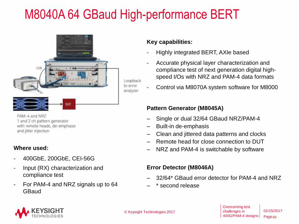
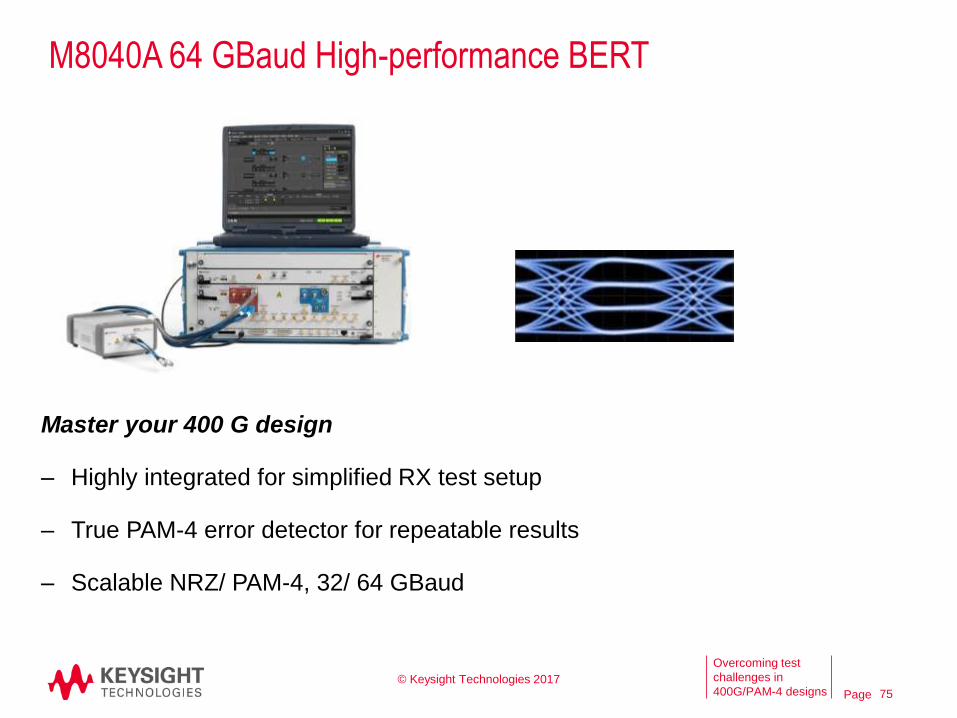
M8040A 64 GBaud High-performance BERT
Key capabilities:
- Highly integrated BERT, AXIe based
- Accurate physical layer characterization and
compliance test of next generation digital high-
speed I/Os with NRZ and PAM-4 data formats
- Control via M8070A system software for M8000
Pattern Generator (M8045A)
‒ Single or dual 32/64 GBaud NRZ/PAM-4
‒ Built-in de-emphasis
‒ Clean and jittered data patterns and clocks
‒ Remote head for close connection to DUT
‒ NRZ and PAM-4 is switchable by software
Error Detector (M8046A)
‒ 32/64* GBaud error detector for PAM-4 and NRZ
‒ * second release
Where used:
- 400GbE, 200GbE, CEI-56G
- Input (RX) characterization and
compliance test
- For PAM-4 and NRZ signals up to 64
GBaud
60
© Keysight Technologies 2017 02/15/2017
Page
Overcoming test
challenges in
400G/PAM-4 designs
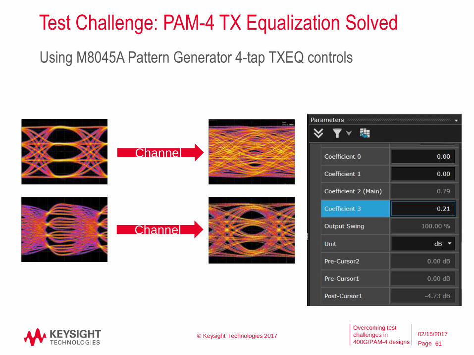
Test Challenge: PAM-4 TX Equalization Solved
61
Using M8045A Pattern Generator 4-tap TXEQ controls
© Keysight Technologies 2017
Channel
Channel
02/15/2017
Page
Overcoming test
challenges in
400G/PAM-4 designs
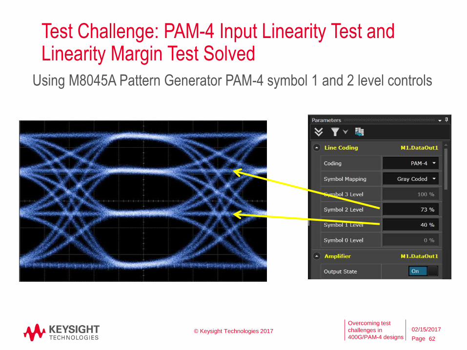
Test Challenge: PAM-4 Input Linearity Test and Linearity Margin Test Solved
62
Using M8045A Pattern Generator PAM-4 symbol 1 and 2 level controls
© Keysight Technologies 2017 02/15/2017
Page
Overcoming test
challenges in
400G/PAM-4 designs 63
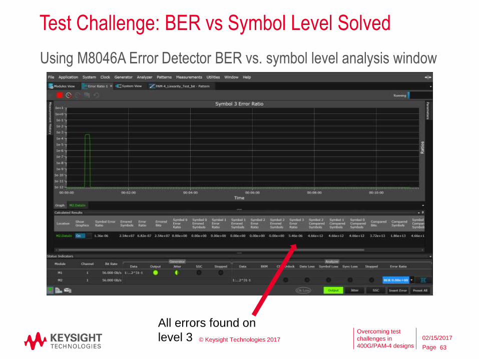
Using M8046A Error Detector BER vs. symbol level analysis window
All errors found on
level 3 © Keysight Technologies 2017
Test Challenge: BER vs Symbol Level Solved
02/15/2017
Page
Overcoming test
challenges in
400G/PAM-4 designs
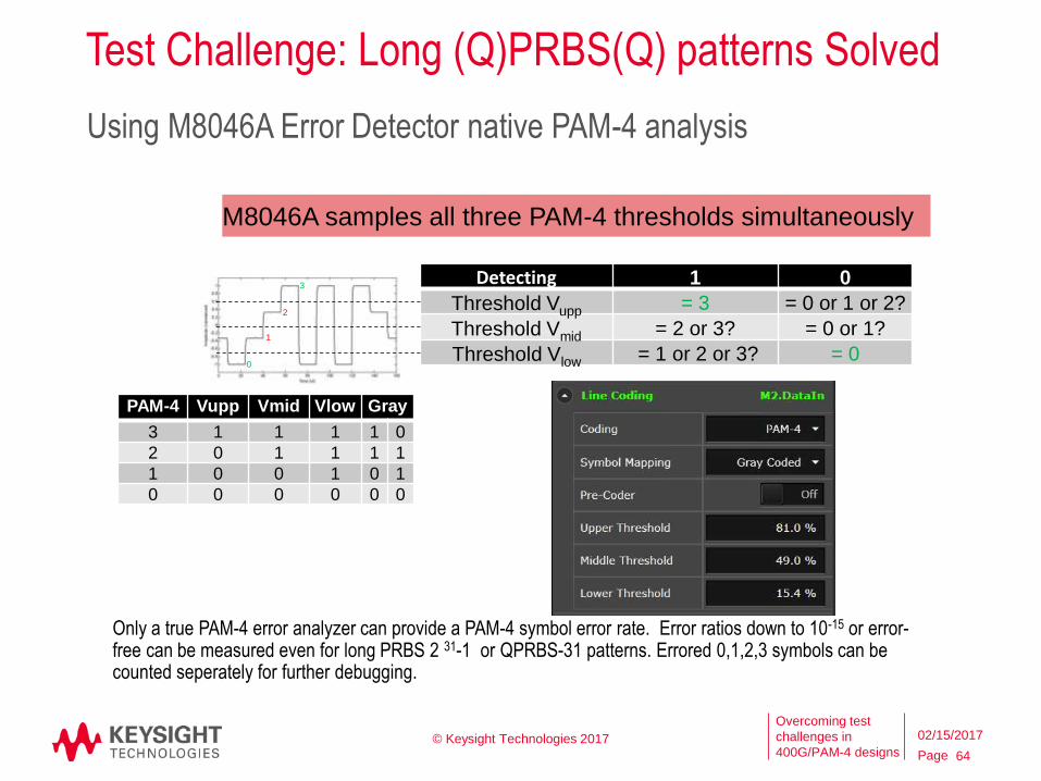
Test Challenge: Long (Q)PRBS(Q) patterns Solved
64
Using M8046A Error Detector native PAM-4 analysis
Data In
Detecting 1 0
Threshold Vupp = 3 = 0 or 1 or 2?
Threshold Vmid = 2 or 3? = 0 or 1?
Threshold Vlow = 1 or 2 or 3? = 0
3
0
1
2
PAM-4 Vupp Vmid Vlow Gray
3 1 1 1 1 0
2 0 1 1 1 1
1 0 0 1 0 1
0 0 0 0 0 0
Only a true PAM-4 error analyzer can provide a PAM-4 symbol error rate. Error ratios down to 10-15 or error-free can be measured even for long PRBS 2 31-1 or QPRBS-31 patterns. Errored 0,1,2,3 symbols can be counted seperately for further debugging.
M8046A samples all three PAM-4 thresholds simultaneously
© Keysight Technologies 2017 02/15/2017
Page
Overcoming test
challenges in
400G/PAM-4 designs
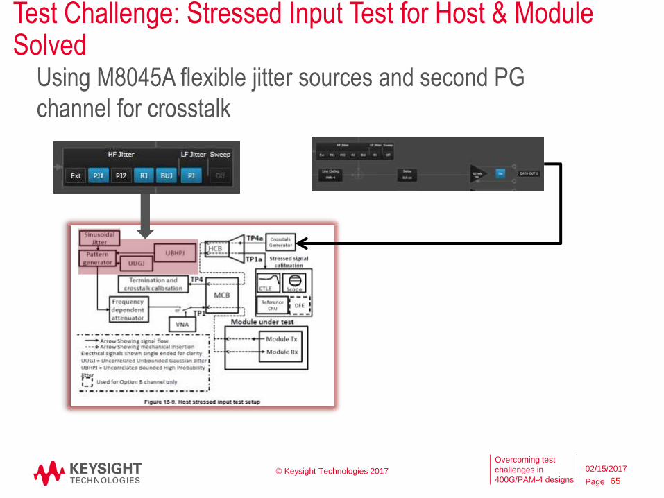
Test Challenge: Stressed Input Test for Host & Module Solved
65
Using M8045A flexible jitter sources and second PG
channel for crosstalk
© Keysight Technologies 2017 02/15/2017
Page
Overcoming test
challenges in
400G/PAM-4 designs
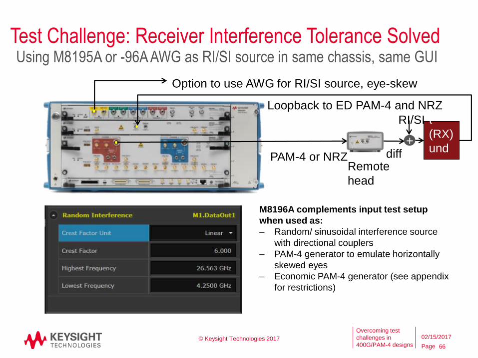
Test Challenge: Receiver Interference Tolerance Solved
66
Inpu
t
(RX)
und
er
test
Loopback to ED PAM-4 and NRZ
diffPAM-4 or NRZRemote
head
M8196A complements input test setup
when used as:
‒ Random/ sinusoidal interference source
with directional couplers
‒ PAM-4 generator to emulate horizontally
skewed eyes
‒ Economic PAM-4 generator (see appendix
for restrictions)
+
Option to use AWG for RI/SI source, eye-skew
RI/SI
Using M8195A or -96A AWG as RI/SI source in same chassis, same GUI
© Keysight Technologies 2017 02/15/2017
Page
Overcoming test
challenges in
400G/PAM-4 designs
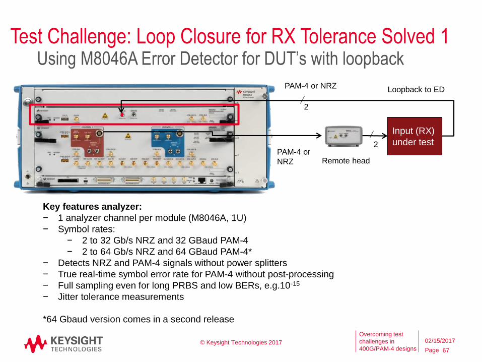
Test Challenge: Loop Closure for RX Tolerance Solved 1
67
Using M8046A Error Detector for DUT’s with loopback
Input (RX)
under test
2
PAM-4 or
NRZ Remote head
Loopback to EDPAM-4 or NRZ
2
Key features analyzer:
− 1 analyzer channel per module (M8046A, 1U)
− Symbol rates:
− 2 to 32 Gb/s NRZ and 32 GBaud PAM-4
− 2 to 64 Gb/s NRZ and 64 GBaud PAM-4*
− Detects NRZ and PAM-4 signals without power splitters
− True real-time symbol error rate for PAM-4 without post-processing
− Full sampling even for long PRBS and low BERs, e.g.10-15
− Jitter tolerance measurements
*64 Gbaud version comes in a second release
© Keysight Technologies 2017 02/15/2017
Page
Overcoming test
challenges in
400G/PAM-4 designs
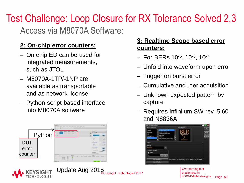
2: On-chip error counters:
‒ On chip ED can be used for
integrated measurements,
such as JTOL
‒ M8070A-1TP/-1NP are
available as transportable
and as network license
‒ Python-script based interface
into M8070A software
68
Access via M8070A Software:3: Realtime Scope based error
counters:
– For BERs 10-5, 10-6, 10-7
– Unfold into waveform upon error
– Trigger on burst error
– Cumulative and „per acquisition“
– Unknown expected pattern by
capture
– Requires Infiniium SW rev. 5.60
and N8836A
DUT
error
counter
Python
Update Aug 2016
Test Challenge: Loop Closure for RX Tolerance Solved 2,3
© Keysight Technologies 2017
Page
Overcoming test
challenges in
400G/PAM-4 designs
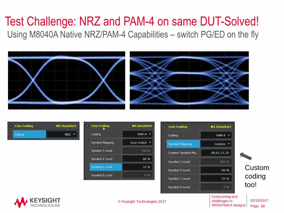
Test Challenge: NRZ and PAM-4 on same DUT-Solved!
69
Using M8040A Native NRZ/PAM-4 Capabilities – switch PG/ED on the fly
Custom
coding
too!
© Keysight Technologies 2017 02/15/2017
Page
Overcoming test
challenges in
400G/PAM-4 designs
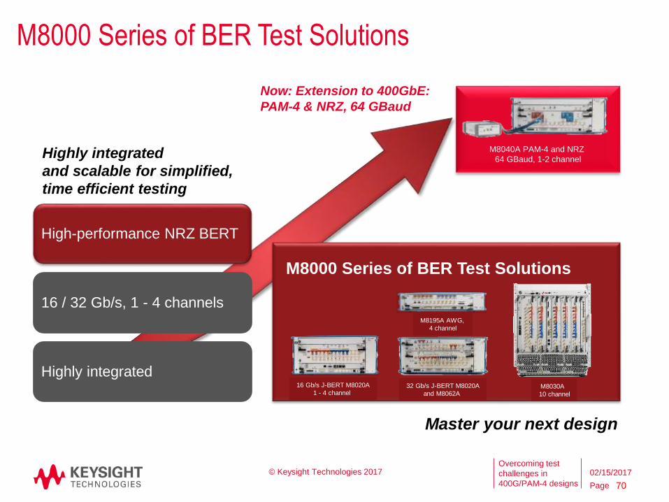
M8000 Series of BER Test Solutions
Master your next design
Highly integrated
and scalable for simplified,
time efficient testing
Now: Extension to 400GbE:
PAM-4 & NRZ, 64 GBaud
M8040A PAM-4 and NRZ
64 GBaud, 1-2 channel
16 Gb/s J-BERT M8020A
1 - 4 channel 32 Gb/s J-BERT M8020A
and M8062A
M8000 Series of BER Test Solutions
M8195A AWG,
4 channel
M8030A
10 channel
70
High-performance NRZ BERT
16 / 32 Gb/s, 1 - 4 channels
Highly integrated
© Keysight Technologies 2017 02/15/2017
Page
Overcoming test
challenges in
400G/PAM-4 designs
Summary
• Transition from NRZ to PAM-4 is revolutionary
• Many new challenges in both electrical and optical links
• Required Output (Tx) measurements and Input (Rx) stress types are
changing
• New eye measurements for PAM-4 Output tests (e.g. TDECQ,
JRMS, J4, …)
• Linearity added to stressed Input testing
• New tools are needed for characterizing and troubleshooting links
using FEC
• Learn more on the web at: www.keysight.com/find/pam4
© Keysight Technologies 2017 71
02/15/2017

Page
Overcoming test
challenges in
400G/PAM-4 designs © Keysight Technologies 2017 72
02/15/2017
Page
Overcoming test
challenges in
400G/PAM-4 designs
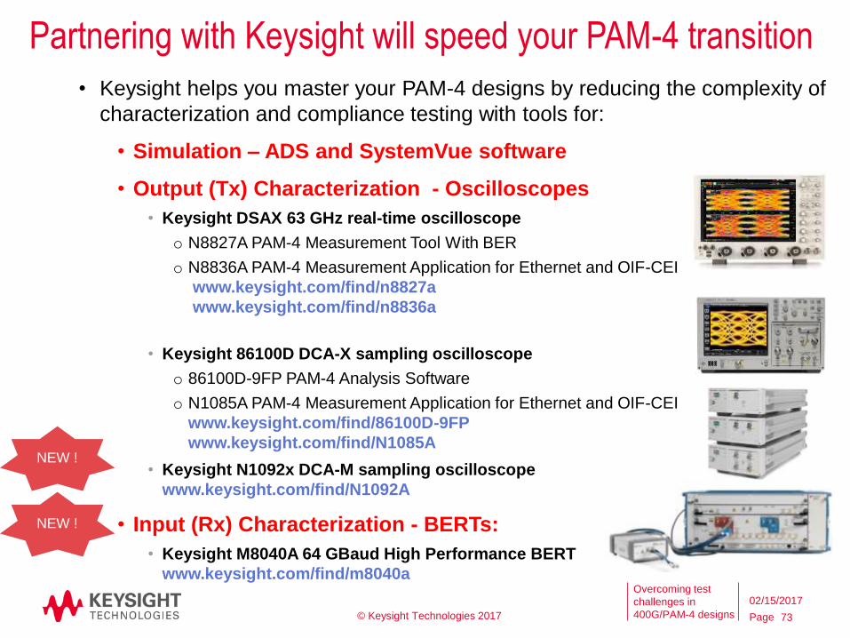
Partnering with Keysight will speed your PAM-4 transition
• Keysight helps you master your PAM-4 designs by reducing the complexity of
characterization and compliance testing with tools for:
• Simulation – ADS and SystemVue software
• Output (Tx) Characterization - Oscilloscopes
• Keysight DSAX 63 GHz real-time oscilloscope
o N8827A PAM-4 Measurement Tool With BER
o N8836A PAM-4 Measurement Application for Ethernet and OIF-CEI
www.keysight.com/find/n8827a
www.keysight.com/find/n8836a
• Keysight 86100D DCA-X sampling oscilloscope
o 86100D-9FP PAM-4 Analysis Software
o N1085A PAM-4 Measurement Application for Ethernet and OIF-CEI
www.keysight.com/find/86100D-9FP
www.keysight.com/find/N1085A
• Keysight N1092x DCA-M sampling oscilloscope
www.keysight.com/find/N1092A
• Input (Rx) Characterization - BERTs:
• Keysight M8040A 64 GBaud High Performance BERT
www.keysight.com/find/m8040a
NEW !
NEW !
© Keysight Technologies 2017 73
02/15/2017
Page
Overcoming test
challenges in
400G/PAM-4 designs
Acronymsc2c = Chip-to-Chip
c2m = Chip-to-Module
BER = Bit Error Ratio
BUJ = Bounded Uncorrelated Jitter (used to emulate crosstalk)
DUT = Device Under Test
EW = Eye Width
EH = Eye Height
FEC = Forward Error Correction
FFE = Feed-Forward Equalizer
NRZ = Non-Return to Zero (Refers to 2 level signaling or PAM-2)
PAM-n = Pulse Amplitude Modulation, where n = number of levels
RJ = Random Jitter
RS = Reed-Solomon
SER = Symbol Error Ratio
SIRC = System Impulse Response Correction
SJ = Sinusoidal Jitter
SMF/MM F– Single-mode fiber, Multimode fiber
TDP = Transmitter and Dispersion Penalty
TDEC = Transmitter and Dispersion Eye Closure
TDECQ = Transmitter and dispersion eye closure quaternary (for PAM-4)
© Keysight Technologies 2017 74
02/15/2017
Page
Overcoming test
challenges in
400G/PAM-4 designs
Master your 400 G design
‒ Highly integrated for simplified RX test setup
‒ True PAM-4 error detector for repeatable results
‒ Scalable NRZ/ PAM-4, 32/ 64 GBaud
M8040A 64 GBaud High-performance BERT
75
© Keysight Technologies 2017