Embed Size (px)
Citation preview
Keysight TechnologiesTesting Handovers Between LTE and 3G cdma2000/1xEV-DO Cellular Networks
Application Note
2
The global telecommunications market is witnessing a paradigm shift in demand
as mobile data revenues surpass voice-based revenues in most western
countries. Wireless network operators are focusing on expanding revenues in
broadband services, where wireless technologies are perceived by users in the
light of cable- and DSL-based broadband wired access. The rapid growth of
mobile broadband is driven by demand for the latest devices, applications and
services, which enable users to access any type of content on the move. This is
driving up data usage on mobile networks at a tremendous rate, and operators
need to respond with bandwidth availability, which in turn provides the driving
force behind the development of evolved 3G and 4G systems such as 1xEV-DO
revision A/B and LTE.
Long Term Evolution (LTE) is the project name given by 3GPP to the evolution
of the UMTS 3G radio standards. The work on enhancing the original UMTS
Terrestrial Radio Access (UTRA) continues in Release 8 of the 3GPP standards
with enhancements to High Speed Packet Access (HSPA), but in addition
Release 8 includes LTE, an entirely new air interface based on OFDM technology.
The formal name for LTE is the Evolved UMTS Terrestrial Radio Access (E-UTRA)
but it is more widely known by its project name of LTE. Offering higher data
rates and lower latency for the user, a simplified all-IP network for the operator
and improved spectral efficiency, E-UTRA – or LTE – promises to provide many
benefits. In many cases, operators who previously delivered services using
3GPP2 network technologies – cdma2000 for data and voice and 1xEV-DO for
enhanced data – have chosen LTE as their next-generation option. While this
looks like a step towards a worldwide standard for the future, it gives them
some immediate problems with the integration of new and legacy networks.
LTE as part of the cellular infrastructure
LTE is an all-IP system, designed primarily to provide high-speed data services.
Therefore, during network build-out, and until operators choose to implement
IP-based voice services, LTE networks will utilize 2G and 3G as an underlying
infrastructure for voice calls, and for data services where no LTE service is yet
provided. In normal operation, the mobile device (User Equipment, or UE) is
required to scan for neighbor cells and generate reports which are used as a
basis for cell selection and handover decisions. The processes involved are very
demanding for today’s UEs, which must also multi-task a large number of other
applications, making heavy demands on processor power. The consequence
of inadequate UE response times can be slow (or no) handover, and poor user
experience such as dropped connections and frozen applications.
Industry research predicts that LTE is likely to experience its most rapid growth
from 2012, when the majority of operators launch their networks and a unified
approach to delivering voice communications and rich services such as video
telephony over LTE become available.
Why Test Handovers Between LTE and Third Generation cdma2000/1xEV-DO Cellular Networks?
Section 1. Introduction
3
Because LTE coverage will not be pervasive, testing handover capability
between different radio access technologies (RAT) is critically important in the
verification of UEs. For a positive end-user experience UEs need to transition
smoothly between these RATs, which leads operators to increase their focus
on testing the real-world performance of each device before deployment on
their networks. Such performance testing goes well beyond the more traditional
conformance tests defined by the industry’s standards bodies.
Compliance tests are used across the development cycle for cellular products.
Sensitivity, spectral and modulation quality measurements are traceable to
techniques defined by industry standards bodies. The 3GPP core specifications
are necessary to design an LTE UE, and conformance tests define how to
measure compliance with these specifications. Organizations such as the GCF
(Global Certification Forum, an active partnership among network operators)
and PTCRB (originally named PCS Type Certification Review Board – for North
American network operators) govern the certification process, setting standards
and accrediting a global network of laboratories to undertake conformance
testing. GCF and PRCRB test regimes, operator test plans, performance and
interoperability test have grown dramatically with newer radio formats and more
capable UEs. Equipment makers build their design verification, pre-conformance
and regression test plans to enable products to move smoothly from the
development lab to production in the shortest possible time.
Conformance test might be taken as an industry requirement – ensuring the UE
supports a level of functionality and does not cause a problem on the system
or to other users – where performance test gives the UE manufacturer the
opportunity to differentiate their device based on better user experience:
application speed, battery life and generally how the UE fulfills expectations.
Inter-RAT handovers are part of both, and assume different importance depending
on what the UE is currently doing. If it’s idle (not using network resources),
conformance issues are the main concern. If, however, the user has a data-hun-
gry application active, performance issues become much more important. In idle
mode, network selection decisions are made mainly by the UE, and transmitted
to the network. Where the UE has an active data connection, the network will
decide the transmission channel, based on its own measurements and neighbor
cell measurement data returned from the UE.
A second criterion for Inter-RAT handover is the need for a voice service. Since
LTE is a packet-only service, with no provision for the circuit-switched voice
connection that is normal in earlier systems, making or receiving a voice call
will not be part of an LTE service until standards for the support of voice are
implemented. Meantime, many operators are investing in LTE alongside existing
voice networks which offer more extensive coverage. In this scenario it makes
sense to use the LTE connection for data and the existing network for voice.
4
Network evolution in the “GSM” world
For operators in much of the world, where current networks are 3GPP GSM/
W-CDMA/HSPA, there’s a natural evolution to LTE, and standards-based
support for full backward and forward compatibility, both in the radio access
network and the core network that lies behind it. The final goal is the inclusion of
Voice over Internet Protocol (VoIP) as part of LTE, making it easier for operators
to run IP-only networks, and full E-UTRA handover to minimize data connection
disruption. In the initial network implementations, losing LTE service or making/
receiving a voice call will cause an automatic fall-back to a 3G bearer, where
both voice and data service can be provided. Voice service is then provided by a
circuit-switched fall-back mechanism, and continuing data service managed by
radio resource release and re-assignment messages. The current specifications
contain fall-back scenarios all the way back to a basic GSM/GPRS connection
if that is the only available network infrastructure. Release 9 includes improve-
ments to circuit-switched fall-back to improve access speed, so there’s no
immediate pressure on operators to move forward with LTE voice.
Integrating LTE with “non-GSM” networks
While there is support in LTE for the discovery and measurement of neighbor
3GPP2 cdma2000/1xEV-DO cells at the air interface level, the core LTE and
3GPP2 networks have major differences. The first LTE implementations will
support only “non-optimized” handovers where, when the UE loses LTE service
it has to acquire 1xEV-DO service. If it has previously been connected to a local
1xEV-DO cell, this may happen relatively quickly, if not it will take much longer.
In idle mode this is not really an issue, but during an active data session
changing network will cause some disruption. Later implementations will
support “optimized” handovers where the UE will be directed to a new serving
cell and have much more information about it. To ensure the UE connects to LTE
service where it is available, LTE is set as the “preferred service” by the network
operator. Voice service is always supplied by a separate cdma2000 radio in the
UE, and known as simultaneous voice and LTE (SVLTE); there is no integration of
voice and data services, and battery power consumption is compromised. Later
LTE specification releases and changes to the 3GPP2 core network will address
data and voice integration, with the goal of providing the same final solution as
the 3GPP case. However, there is an additional level of complexity as the solu-
tion needs to accommodate not just the transition between different physical
layer technologies but also interworking between separate core networks. To
support this, “tunneling” between 3GPP and 3GPP2 core networks is required.
This allows the UE to perform, for instance, pre-registration on the 3GPP2
network while still connected to LTE, speeding the handover process when a
cell change is required.
5
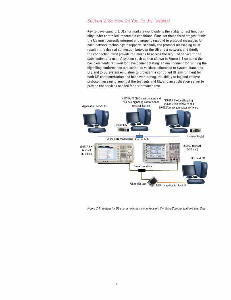
Key to developing LTE UEs for markets worldwide is the ability to test function-
ality under controlled, repeatable conditions. Consider these three stages: firstly,
the UE must correctly interpret and properly respond to protocol messages for
each network technology it supports; secondly the protocol messaging must
result in the desired connection between the UE and a network; and thirdly
the connection must provide the means to access the required service to the
satisfaction of a user. A system such as that shown in Figure 2-1 contains the
basic elements required for development testing: an environment for running the
signalling conformance test scripts to validate adherence to system standards,
LTE and 2/3G system emulation to provide the controlled RF environment for
both UE characterization and handover testing, the ability to log and analyze
protocol messaging amongst the test sets and UE, and an application server to
provide the services needed for performance test.
Figure 2-1. System for UE characterization using Keysight Wireless Communications Test Sets
Section 2. So How Do You Do the Testing?

6
More comprehensive systems can be used to provide a more complex RF
environment for testing – for example additional test sets to provide multiple
neighbor cells and both 2G and 3G cells of different technologies, and adding
fading simulators to provide a better representation of a true mobile environment.
Signalling conformance test (sometimes called protocol conformance test) uses
scripts describing specific test cases and provided by accredited standards
organizations, and is the basis for proving interoperability. The device must pass
the required cases for each technology that it supports. The TTCN- 3 (Test and
Testing Control Notation version 3) Environment shown in the figure provides a
graphic user interface and software test framework. The tool enables TTCN- 3
test cases to be loaded, edited or created, compiled and executed. It includes
logging functions and the ability to automate sequences of tests or campaigns.
To enable test case portability from one test platform to another, the functions
available to a TTCN- 3 programmer through the TRI (TTCN- 3 Run Time
Interface) have been standardized by ETSI. Manufacturers provide the standard
TTCN-3 compiled test cases and an adaptor that connects the standardized TRI
interface available to programmers to the unique characteristics of their test
instrumentation. This testing is typically done under good RF conditions, and
the goal is to demonstrate that the UE responds correctly during a sequence
of protocol messages. Pass/fail is determined from the messages and their
content – no parametric measurements are made.
In the RF domain, a test system which can provide cell emulation for different
technologies, including parametric changes and corresponding measurements,
can be used to investigate both the outcome and the timing of inter-RAT
handovers. 3GPP standards cover expected Radio Resource Management (RRM)
behavior between LTE and earlier releases. In the case of operators moving
to LTE from 3GPP2 technologies (cdma2000/1xEV-DO) operators are creating
their own requirements and test plans for handover testing, and working with
suppliers to ensure new UEs meet the needs of their customers. This type of
testing helps UE developers ensure their devices conform to the latest needs
of network operators as the various inter-RAT scenarios are fully specified and
implemented. Table 3-1 lists example tests that might be specified for
Inter-RAT testing.
When the ability to change the RF environment is used in conjunction with a
live application server, it can provide valuable insight into the behavior of both
application and UE behavior during disruptions caused by changes in the RF
channel: for example, RF channel conditions, system handovers, dropped calls,
connection speed changes, and interference from other applications.
1xEV-DO and LTE systems can provide multiple simultaneous connections. The
application server can also be used to ensure the UE handles multiple processes
correctly and in a timely way. Examples might include delivering an SMS during
video streaming, downloading multiple files and using an interactive gaming
application. This capability gives the developer the view of overall device or
application performance that helps differentiate their product from its competitors.
7
Section 3. So Give Me an Example LTE/3GPP2 Partial Handover Test Plan and Show Me a Test
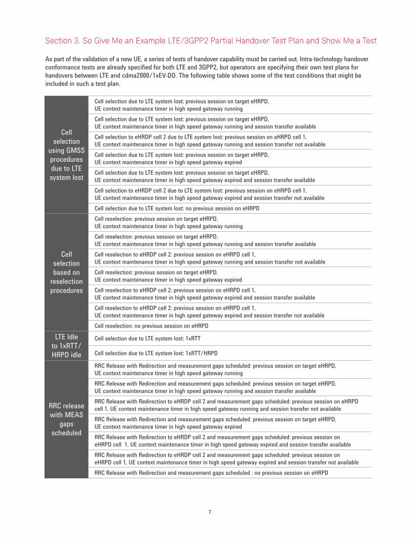
As part of the validation of a new UE, a series of tests of handover capability must be carried out. Intra-technology handover
conformance tests are already specified for both LTE and 3GPP2, but operators are specifying their own test plans for
handovers between LTE and cdma2000/1xEV-DO. The following table shows some of the test conditions that might be
included in such a test plan.
Cell
selection
using GMSS
procedures
due to LTE
system lost
Cell selection due to LTE system lost: previous session on target eHRPD,
UE context maintenance timer in high speed gateway running
Cell selection due to LTE system lost: previous session on target eHRPD,
UE context maintenance timer in high speed gateway running and session transfer available
Cell selection to eHRDP cell 2 due to LTE system lost: previous session on eHRPD cell 1,
UE context maintenance timer in high speed gateway running and session transfer not available
Cell selection due to LTE system lost: previous session on target eHRPD,
UE context maintenance timer in high speed gateway expired
Cell selection due to LTE system lost: previous session on target eHRPD,
UE context maintenance timer in high speed gateway expired and session transfer available
Cell selection to eHRDP cell 2 due to LTE system lost: previous session on eHRPD cell 1,
UE context maintenance timer in high speed gateway expired and session transfer not available
Cell selection due to LTE system lost: no previous session on eHRPD
Cell
selection
based on
reselection
procedures
Cell reselection: previous session on target eHRPD,
UE context maintenance timer in high speed gateway running
Cell reselection: previous session on target eHRPD,
UE context maintenance timer in high speed gateway running and session transfer available
Cell reselection to eHRDP cell 2: previous session on eHRPD cell 1,
UE context maintenance timer in high speed gateway running and session transfer not available
Cell reselection: previous session on target eHRPD,
UE context maintenance timer in high speed gateway expired
Cell reselection to eHRDP cell 2: previous session on eHRPD cell 1,
UE context maintenance timer in high speed gateway expired and session transfer available
Cell reselection to eHRDP cell 2: previous session on eHRPD cell 1,
UE context maintenance timer in high speed gateway expired and session transfer not available
Cell reselection: no previous session on eHRPD
LTE Idle
to 1xRTT/
HRPD idle
Cell selection due to LTE system lost: 1xRTT
Cell selection due to LTE system lost: 1xRTT/HRPD
RRC release
with MEAS
gaps
scheduled
RRC Release with Redirection and measurement gaps scheduled: previous session on target eHRPD,
UE context maintenance timer in high speed gateway running
RRC Release with Redirection and measurement gaps scheduled: previous session on target eHRPD,
UE context maintenance timer in high speed gateway running and session transfer available
RRC Release with Redirection to eHRDP cell 2 and measurement gaps scheduled: previous session on eHRPD
cell 1, UE context maintenance timer in high speed gateway running and session transfer not available
RRC Release with Redirection and measurement gaps scheduled: previous session on target eHRPD,
UE context maintenance timer in high speed gateway expired
RRC Release with Redirection to eHRDP cell 2 and measurement gaps scheduled: previous session on
eHRPD cell 1, UE context maintenance timer in high speed gateway expired and session transfer available
RRC Release with Redirection to eHRDP cell 2 and measurement gaps scheduled: previous session on
eHRPD cell 1, UE context maintenance timer in high speed gateway expired and session transfer not available
RRC Release with Redirection and measurement gaps scheduled : no previous session on eHRPD
8
Example test details
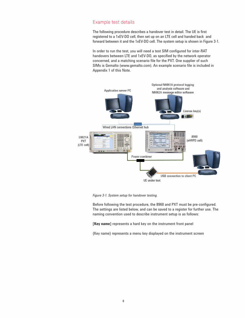
The following procedure describes a handover test in detail. The UE is first
registered to a 1xEV-DO cell, then set up on an LTE cell and handed back and
forward between it and the 1xEV-DO cell. The system setup is shown in Figure 3-1.
In order to run the test, you will need a test SIM configured for inter-RAT
handovers between LTE and 1xEV-DO, as specified by the network operator
concerned, and a matching scenario file for the PXT. One supplier of such
SIMs is Gemalto (www.gemalto.com). An example scenario file is included in
Appendix 1 of this Note.
Figure 3-1. System setup for handover testing.
Before following the test procedure, the 8960 and PXT must be pre-configured.
The settings are listed below, and can be saved to a register for further use. The
naming convention used to describe instrument setup is as follows:
[Key name] represents a hard key on the instrument front panel
{Key name} represents a menu key displayed on the instrument screen
9
Presetting the instruments
Both the E6621A and the 8960 should be in their ‘preset’ states before
executing each test case.
PXT (LTE Cell)
Select [Preset] -> {Preset}
8960 (eHRPD Cell)
Select [Shift] -> [Preset]
LAN IP Addresses
Set the IP addresses of the PXT, 8960, EPC and server PC as follows:
Table 1. System IP addresses
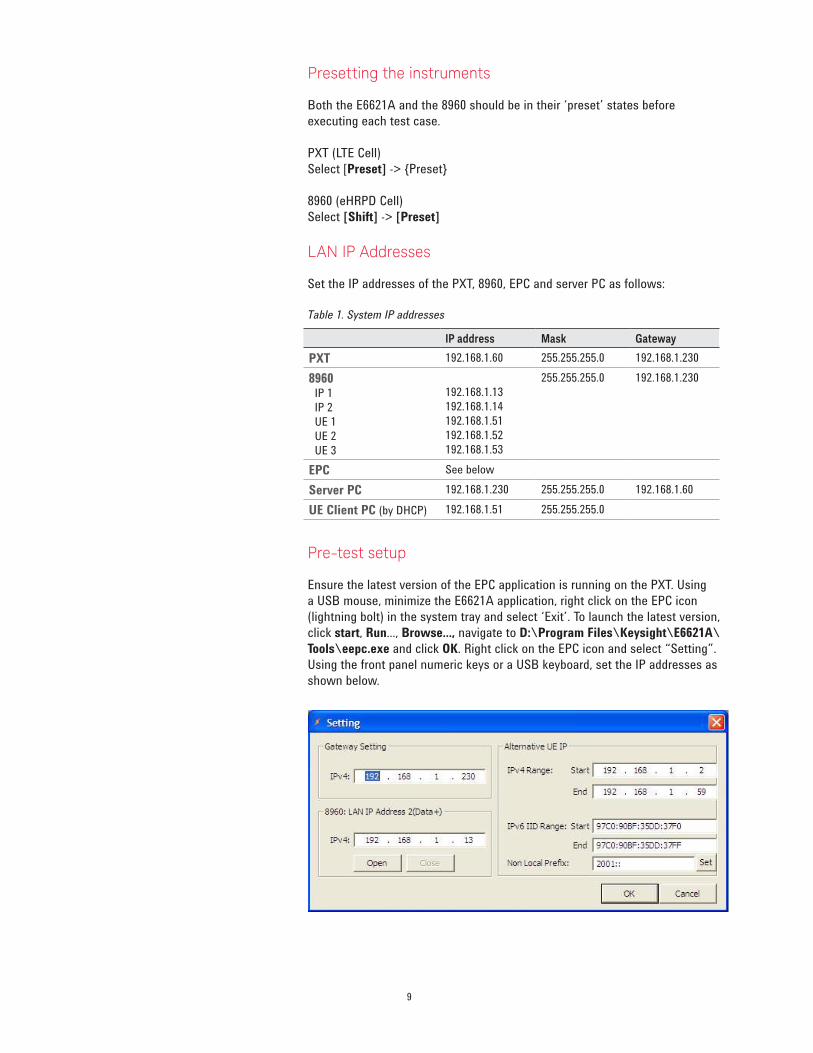
Pre-test setup
Ensure the latest version of the EPC application is running on the PXT. Using
a USB mouse, minimize the E6621A application, right click on the EPC icon
(lightning bolt) in the system tray and select ‘Exit’. To launch the latest version,
click start, Run..., Browse..., navigate to D:\Program Files\Keysight\E6621A\
Tools\eepc.exe and click OK. Right click on the EPC icon and select “Setting”.
Using the front panel numeric keys or a USB keyboard, set the IP addresses as
shown below.
IP address Mask Gateway
PXT 192.168.1.60 255.255.255.0 192.168.1.230
8960 IP 1
IP 2
UE 1
UE 2
UE 3
192.168.1.13
192.168.1.14
192.168.1.51
192.168.1.52
192.168.1.53
255.255.255.0 192.168.1.230
EPC See below
Server PC 192.168.1.230 255.255.255.0 192.168.1.60
UE Client PC (by DHCP) 192.168.1.51 255.255.255.0
10
PXT (LTE cell)
– Load Register 1 [Recall] {Recall State} {Register 1}
– Turn off [RF1] and [RF2]
If Register 1 has not already been saved, the following setup needs to be done:
Create the required scenario file using the instructions in Appendix 1. Using a
USB mouse, minimize the E6621A application and copy the scenario file onto
the PXT from the USB memory stick to the Windows directory D:\Program
Files\Keysight\E6621A\LTE-Scenario
Set the PXT as follows:
Select [Mode Setup] -> {EPC} -> {Embed}
Select [Freq] -> {Center (DL)} -> [751] -> {MHz}
Select [Freq] -> {Center (UL)} -> [782] -> {MHz}
Select [Amp] -> {RF1 Amplitude} -> [-31] -> {dBm}
Select [Amp] -> {RF2 Amplitude} -> [-31] -> {dBm}
Select [Atten] -> {RF1 Ref Level} -> [-43] -> {dBm}
Select [Mode Setup] -> [More (2/2)] -> {PHY Settings} ->
{UL Resource Allocation} -> {I_MCS} -> [5] -> {Enter}
Select [Mode Setup] -> [More (2/2)] -> {PHY Settings} ->
{UL Resource Allocation} -> {RB Size} -> [20]->{Enter}
Select [Mode Setup] -> [More (2/2)] -> {Security} -> {Off}
Select [Mode Setup] -> {Call Scenario} scroll to required filename {Load}
Save for future use:
Select [Save] -> {Save State} -> {Register 1}
The saved state includes the above settings, including the scenario file information.
8960 (eHRPD cell)
Ensure the 1xEV-DO Lab App is selected: [SYSTEM CONFIG] -> {Format Switch
[F2]} -> IS-856
Ensure the external EPC is disconnected: [LH Menu, MORE] -> {2 of 3} ->
{eUTRAN/eHRPD Interworking Info [F6]} -> {Disconnect from External EPC [F2]}
Setup the IP addresses: [SYSTEM CONFIG] -> {Instrument Setup [F1]}
LAN IP Address }
Subnet Mask } see Table 1
Default Gateway }
LAN IP Address 2 (Data+) }
Set the PDN IP –
[CALL SETUP] -> [LH Menu, MORE] -> {3 of 3} -> {Data Channel Info [F2]} ->
[LHMenu, MORE] -> {2 of 2} -> {IP Addressing Info [F5]} -> {DUT IP Setup [F2]}
DUT IP Address } see Table 1
DUT IP Address 2 }

11
Setup the EPC IP: [CALL SETUP] -> [LHMenu, MORE] -> {2 of 3} ->
{E-UTRAN/eHRPD Interworking Info [F6]} -> {Ext EPC IP Addr [F1]} see Table 1
Set up the eHRPD parameters: [CALL SETUP] -> [RHMenu, MORE] -> {2 of 3} ->
{Protocol Rel [F11]} -> A (1xEV-DO-A)
Select [CALL SETUP] -> [RHMenu, MORE] -> {1 of 3} ->
{Application Config [F10]} -> {Session Application Type (Press knob for options)} ->
Alternate EMPA
Select [CALL SETUP] -> [RHMenu, MORE] -> {1 of 3} -> {Cell Power [F7]} ->
[-35] -> [ENTER]
{Cell Band} -> US PCS -> [ENTER], {Channel} -> [375] -> [ENTER]
Set the Session Close Timeout to 100 minutes: [CALL SETUP] ->
[RHMenu, MORE] -> {3 of 3} -> {Session Close} -> [100] -> [ENTER]
Setup the Preferred Control Channel Cycle Control: [CALL SETUP] ->
[LHMenu, MORE] -> {2 of 3} -> {Access Network Info [F2]} ->
{Configurable Attributes Info [F1]} -> {Configurable Attribute Parms [F1]} ->
{Preferred Control Channel Cycle Control} -> press knob for options -> AT
Specified -> [ENTER]
Set the Sector ID to ‘00800580000000000000000000000000’and the Color Code
to 26:
Call Setup ->
[CALL SETUP] -> [LHMenu, MORE] -> {2 of 3} -> {Access Network Info [F2]} ->
{Cell Parameters [F2]} ->
Sector ID, Upper (Hex) -> [00800580] -> [ENTER]
Sector ID, Upper Middle (Hex) -> [00000000] -> [ENTER]
Sector ID, Lower Middle (Hex) -> [00000000] -> [ENTER]
Sector ID, Lower (Hex) -> [00000000] -> [ENTER]
Color Code -> [26] -> [ENTER]
Set Authentication: [CALL SETUP] -> [LHMenu, MORE] -> {3 of 3} ->
{Data Channel Info [F2]} -> [LHMenu, MORE] -> {2 of 2} ->
{EAP-AKA’ Auth Info [F1]} -> {Authentication Parameters [F1]}
Authentication State }
Authentication Key (K) (Hex) } Set to match your SIM
Operator Variant Parameter Type }
Operator Variant Parameter Value (Hex) ->
[E8ED289DEBA952E4283B54E88E6183CA] -> [ENTER]
Randon (RAND) Value (Hex) -> [01234567890123456789012345678900] ->
[ENTER]
Authentication Management Field (AMF) (Hex) -> [B9B9] -> [ENTER]
Save in Register 1 for future recall: [SAVE] -> {Save Register 1} -> [ENTER]
12
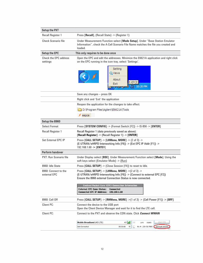
Setup the PXT
Recall Register 1 Press [Recall], {Recall State} -> {Register 1}
Check Scenario file Under Measurement/Function select [Mode Setup]. Under “Base Station Emulator
Information”, check the A-Cell Scenario File Name matches the file you created and
loaded.
Setup the EPC This only requires to be done once
Check the EPC address
settings
Open the EPC and edit the addresses. Minimize the E6621A application and right click
on the EPC running in the icon tray, select ‘Settings’.
Save any changes – press OK
Right click and ‘Exit’ the application
Reopen the application for the changes to take effect.
Setup the 8960
Select Format Press [SYSTEM CONFIG] -> {Format Switch [F2]} -> IS-856 -> [ENTER]
Recall Register 1 Recall Register 1 (data previously saved as above):
[Recall Register] -> {Recall Register 1} -> [ENTER]
Set External EPC IP Press [CALL SETUP] -> [LHMenu, MORE] -> {2 of 3} ->
{E-UTRAN/eHRPD Interworking Info [F6]} -> {Ext EPC IP Addr [F1]} ->
192.168.1.60 -> [ENTER]
Perform handover
PXT: Run Scenario file Under Display select [BSE]. Under Measurement/Function select [Mode]. Using the
soft keys select {Emulator Mode} -> {Run}
8960: Idle State Press [CALL SETUP] -> {Close Session [F4]} to reset to Idle.
8960: Connect to the
external EPC
Press [CALL SETUP] -> [LHMenu, MORE] ->{2 of 3} ->
{E-UTRAN/eHRPD Interworking Info [F6]} -> {Connect to external EPC [F2]}
Ensure the 8960 external Connection Status is now connected.
8960: Cell Off Press [CALL SETUP] -> [RHMenu, MORE] ->{1 of 3} -> {Cell Power [F1]} -> [OFF]
Client PC: Connect the device to the USB port
Open the Client Device Manager and wait for it to find the LTE cell.
Client PC: Connect to the PXT and observe the CON state. Click Connect WWAN
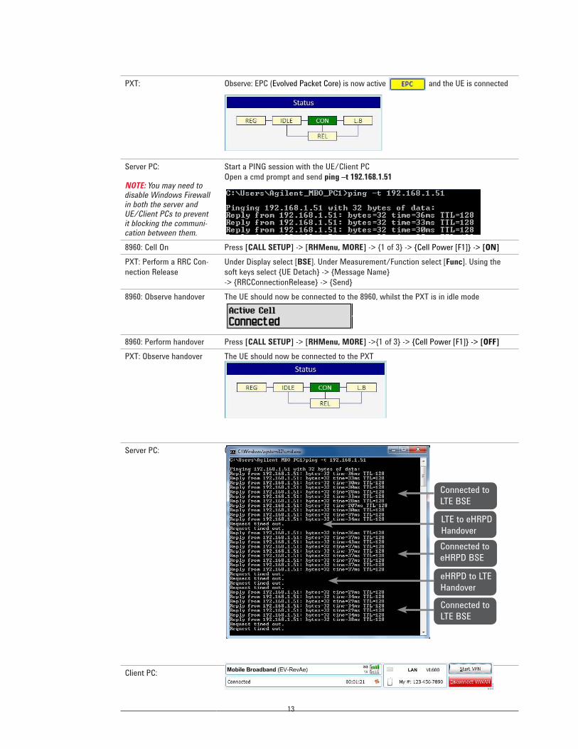
13
PXT: Observe: EPC (Evolved Packet Core) is now active and the UE is connected
Server PC:
NOTE: You may need to disable Windows Firewall in both the server and UE/Client PCs to prevent it blocking the communi-cation between them.
Start a PING session with the UE/Client PC
Open a cmd prompt and send ping –t 192.168.1.51
8960: Cell On Press [CALL SETUP] -> [RHMenu, MORE] -> {1 of 3} -> {Cell Power [F1]} -> [ON]
PXT: Perform a RRC Con-
nection Release
Under Display select [BSE]. Under Measurement/Function select [Func]. Using the
soft keys select {UE Detach} -> {Message Name}
-> {RRCConnectionRelease} -> {Send}
8960: Observe handover The UE should now be connected to the 8960, whilst the PXT is in idle mode
8960: Perform handover Press [CALL SETUP] -> [RHMenu, MORE] ->{1 of 3} -> {Cell Power [F1]} -> [OFF]
PXT: Observe handover The UE should now be connected to the PXT
Server PC: Observe the data connectivity whilst performing handover
Client PC: Disconnect WWAN Session
Connected to
LTE BSE
LTE to eHRPD
Handover
Connected to
eHRPD BSE
eHRPD to LTE
Handover
Connected to
LTE BSE
14
Appendix 1 – Create and store PXT Scenario File
The PXT requires scenario files that provide it with details of the LTE environ-
ment and various instrument parameters. The files uses the extension “.lbmf”
and reside in a specific directory on the PXT. The basic file needed for the
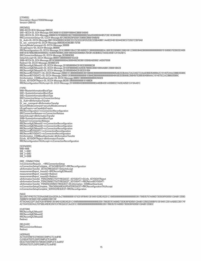
example in this note is listed on the next page; simply copy the text below into
a new file using notepad and check it has no additional characters (eg “Page
Number xx”). When you are sure it is correct, save it with the correct file
extension and note the name. Using N6062A message editor, make the changes
required to match your test SIM and save them. When you are satisfied that
the SIM and scenario file match, copy it to a USB memory stick for installing in
the PXT.
15
[LTEMSG]Description=BasicLTEBSEMessageVersion=2009-03
[RRCMSG]MIB=BCCH-BCH-Message,690C43SIB1=BCCH-DL-SCH-Message,404C469010102000FF0B844C0808104B40SIB2=BCCH-DL-SCH-Message,00800C623F008000C002700000000000029AA55496D044B57C0E10C0040300RRCConnectionSetup=DL-CCCH-Message,60129B3E820F635EF259B0C000010480A0DL_Auth=DL-DCCH-Message,0801203A900B924EB0F2E575CDCEE6FD52EB232BBA98811AA9E5F4B1BD44E90C57326D723DF9A8DL_sec_command=DL-DCCH-Message,0800383AE80388170700SecurityModeCommand=DL-DCCH-Message,300000UEcapEnquiry=DL-DCCH-Message,380000RRCReconfiguration=DL-DCCH-Message,2016108000100A3730F460002313800000000083A1008783200980C2008100122900E0848280000000000000000701B0B83702BB3D34B6B981B1B7B68280E0540099AC192805FB0980C2009180D55DE6000BA7B4381A93B80327A03EA05B1C419AA81CRRCConnectionRelease=DL-DCCH-Message,2820809DB0DetachAccept=DL-DCCH-Message,0800413800000000103A30SIB8=BCCH-DL-SCH-Message,0019C0000000000AE0000408290380103B6BA8D86E1A0D870500Redirect=DL-DCCH-Message,282080C970RRCReconfigA2MeasId1=DL-DCCH-Message,201005800004C81002E000008C00RRCReconfigB2MeasId2=DL-DCCH-Message,20103F800000B2A09DB78000C000018994A000120000108420RRCReconfigA2MeasId3=DL-DCCH-Message,201005000404C81002E01004RRCReconfKEYSIGHT1=DL-DCCH-Message,2006014138000000000C90160848280000000000000000605AB2D2BA4A72A22A92722AA0280E054009A2C191407E44A2388B35589CRRCReconfKEYSIGHT2=DL-DCCH-Message,2006012938000000000B901E08482800000000000000004843B3D3BB0B236B4B70280E054009AAC191407DC2A2388B35589CDLInformation_ESMBearDeactivate=DL-DCCH-Message,08005138000000000B90266920DLInfo_KEYSIGHTReject=DL-DCCH-Message,082051380000000008101688D8RRCReconfigurationTAUAccept=DL-DCCH-Message,201600000493800000000083A480B4381A93B80327A03EA05B1C419AA81C
[TYPE]MIB=MasterInformationBlockTypeSIB1=SystemInformationBlockTypeSIB2=SystemInformationBlockTypeRRCConnectionSetup=rrcConnectionSetupDL_Auth=dlInformationTransferDL_sec_command=dlInformationTransferSecurityModeCommand=securityModeCommandUEcapEnquiry=ueCapabilityEnquiryRRCReconfiguration=rrcConnectionReconfigurationRRCConnectionRelease=rrcConnectionReleaseDetachAccept=dlInformationTransferSIB8=SystemInformationBlockTypeRedirect=rrcConnectionReleaseRRCReconfigA2MeasId1=rrcConnectionReconfigurationRRCReconfigB2MeasId2=rrcConnectionReconfigurationRRCReconfigA2MeasId3=rrcConnectionReconfigurationRRCReconfKEYSIGHT1=rrcConnectionReconfigurationRRCReconfKEYSIGHT2=rrcConnectionReconfigurationDLInformation_ESMBearDeactivate=dlInformationTransferDLInfo_KEYSIGHTReject=dlInformationTransferRRCReconfigurationTAUAccept=rrcConnectionReconfiguration
[SCENARIO]MIB=MIBSIB_1=SIB1SIB_2=SIB2SIB_3=SIB8
[RRC_CONNECTION]rrcConnectionRequest__=RRCConnectionSetuprrcConnectionSetupComplete_ATTACHREQUEST=RRCReconfigurationulInformationTransfer_DETACHREQUEST=DetachAcceptmeasurementReport_measId1=RRCReconfigB2MeasId2measurementReport_measId2=RedirectmeasurementReport_measId3=RedirectulInformationTransfer_PDNCONNECTIVITYREQUEST_KEYSIGHT2=DLInfo_KEYSIGHTRejectulInformationTransfer_PDNCONNECTIVITYREQUEST_KEYSIGHT1=RRCReconfKEYSIGHT1ulInformationTransfer_PDNDISCONNECTREQUEST=DLInformation_ESMBearDeactivaterrcConnectionSetupComplete_TRACKINGAREAUPDATEREQUEST=RRCReconfigurationTAUAcceptrrcConnectionSetupComplete_SERVICEREQUEST=RRCReconfiguration
[NAS]SECURITYPROTECTEDNASMESSAGEDN,0x2700000000010742010F0640130184010200245201C1090500000000000000000E0361706E05767A696D7303636F6D0501C0A801335832500BF6130184012301AABBCC00174FATTACHACCEPT,0x0742010F0640130184010200245201C1090500000000000000000E0361706E05767A696D7303636F6D0501C0A801335832500BF6130184012301AABBCC00174FACTIVATEDEFAULTEPSBEARERCONTEXTREQUEST,0x5201C1090500000000000000000E0361706E05767A696D7303636F6D0501C0A801335832
[CUSTOM]RRCReconfigA2MeasId1RRCReconfigB2MeasId2RRCReconfigA2MeasId3Redirect
[RELEASE]RRCConnectionReleaseRedirect
[ADDNAS]ACTIVATERBTESTMODECOMPLETE,0x0F85CLOSEUETESTLOOPCOMPLETE,0x0F81DEACTIVATERBTESTMODECOMPLETE,0x0F87OPENUETESTLOOPCOMPLETE,0x0F83

For more information on Keysight
Technologies’ products, applications or
services, please contact your local Keysight
office. The complete list is available at:
www.keysight.com/find/contactus
Americas
Canada (877) 894 4414Brazil 55 11 3351 7010Mexico 001 800 254 2440United States (800) 829 4444
Asia PaciicAustralia 1 800 629 485China 800 810 0189Hong Kong 800 938 693India 1 800 112 929Japan 0120 (421) 345Korea 080 769 0800Malaysia 1 800 888 848Singapore 1 800 375 8100Taiwan 0800 047 866Other AP Countries (65) 6375 8100
Europe & Middle East
Austria 0800 001122Belgium 0800 58580Finland 0800 523252France 0805 980333Germany 0800 6270999Ireland 1800 832700Israel 1 809 343051Italy 800 599100Luxembourg +32 800 58580Netherlands 0800 0233200Russia 8800 5009286Spain 0800 000154Sweden 0200 882255Switzerland 0800 805353
Opt. 1 (DE)Opt. 2 (FR)Opt. 3 (IT)
United Kingdom 0800 0260637
For other unlisted countries:
www.keysight.com/find/contactus
(BP-05-29-14)
This information is subject to change without notice.© Keysight Technologies, 2011-2014Published in USA, August 1, 20145990-8362ENwww.keysight.com
myKeysight
www.keysight.com/find/mykeysight
A personalized view into the information most relevant to you.
www.axiestandard.org
AdvancedTCA® Extensions for Instrumentation and Test (AXIe) is an
open standard that extends the AdvancedTCA for general purpose and
semiconductor test. Keysight is a founding member of the AXIe consortium.
www.lxistandard.org
LAN eXtensions for Instruments puts the power of Ethernet and the
Web inside your test systems. Keysight is a founding member of the LXI
consortium.
www.pxisa.org
PCI eXtensions for Instrumentation (PXI) modular instrumentation delivers a
rugged, PC-based high-performance measurement and automation system.
Three-Year Warranty
www.keysight.com/find/ThreeYearWarranty
Keysight’s commitment to superior product quality and lower total cost
of ownership. The only test and measurement company with three-year
warranty standard on all instruments, worldwide.
Keysight Assurance Plans
www.keysight.com/find/AssurancePlans
Up to five years of protection and no budgetary surprises to ensure your
instruments are operating to specification so you can rely on accurate
measurements.
www.keysight.com/quality
Keysight Electronic Measurement Group
DEKRA Certified ISO 9001:2008
Quality Management System
Keysight Channel Partners
www.keysight.com/find/channelpartners
Get the best of both worlds: Keysight’s measurement expertise and product
breadth, combined with channel partner convenience.
www.keysight.com/find/LXE
www.keysight.com/find/PXT
16 | Keysight | Testing Handovers Between LTE and 3G cdma2000/1xEV-DO Cellular Networks