Embed Size (px)
Citation preview

Keysight U2000 SeriesUSB Power SensorsGSM Timeslot Burst Power Measurement
Technical Overview

2
Introduction
Ampli
tude
Time
Figure 1. Power-versus-time measurement graph
Measuring pulse, burst, or modulated signals for wireless technology such as TDMA, GSM, WLAN, WiMAX, and LTE is very important. High-performance, average, and peak power meters and power sensors are required for measuring the average power and crest factor (peak-to-average ratio) of modulated signals throughout various research and development stages and the manufacturing verification process. To measure average power of a time-gated pulse or burst signals (in a specific timeframe), you do not need high-performance power meters and power sensors. The Keysight Technologies, Inc. U2000 Series USB power sensor is a low-cost solution for measuring average power of burst signals with frequency ranges up to 24 GHz and dynamic ranges up to 69 dB (–25 dBm to +44 dBm, sensor dependent).
This document explains the methodology of measuring the time-gated burst signal of the GSM timeslot by using a USB power sensor. It covers the key features of the USB power sensor that allows you to optimize your measurement speed and accuracy. The test setup and SCPI command sequence for both externally triggered and internally triggered measurements are also described in this document.
There are many ways to analyze a modulated signal. Power-versus-time measurement is a very useful method for examining power level changes due to pulsed or burst carriers.
An Affordable Solution for Measuring Burst Power in Time-Gated Mode
Table of ContentIntroduction 2Measuring GSM Timeslot Signal
4
Overview of Keysight U2000 Series USB Power Sensors
5
– Zeroing the USB Power Sensor
5
– Internal zeroing 5 – External zeroing 5
– Measurement Speed 6 – Step Detector 6
Time-Gated Burst Power Measurement (External Triggering)
7
Customer Application of GSM Power Amplifier (PA) Testing in Manufacturing
8
Programming Examples 9Conclusion 11References 11Related Literature 11Related Link 11
Average, pulse, and peak envelope power measurements provide different types of information about the signal. Average power (often simply called power) measures power that is delivered over several cycles. Pulse power is determined by measuring the average power of the pulse and then dividing the result by the pulse duty cycle. This is a mathematical representation of a pulse power rather than an actual measurement and assumes constant pulse power. Pulse-power measurement averages out any aberrations in the pulse, such as overshoot or ringing. For this reason, it is called pulse power and not peak power or peak envelope power. To ensure accurate pulse-power readings, the modulating signal must be a rectangular pulse with a constant duty cycle. Other pulse shapes such as triangular or Gaussian will cause erroneous results. This technique is not applicable for digital modulation systems, where the duty cycle is not constant, and the pulse amplitude and shape is varying.

3
Average power
Peak envelopepower
Pulse power
CW RF signal
Pulsed RF signal
Gaussian pulse signal
Pulse signal Burst signal
Figure 3. Pulse signal with a constant duty cycle versus burst signal without a constant duty cycle
In high-volume power amplifier (PA) module testing environments, power measurement accuracy, test-time efficiency, and test system cost are the key factors for investment consideration. In this case, using high-performance power meters and power sensors incurs costly investment in equipment setup. In order to reduce equipment setup costs, PA manufacturers have chosen to perform time-gated average power measurements of the PA module.
The Keysight U2000 Series USB power sensor is a low-cost solution for average time-gated power measurement of complex modulation signals. It has two trigger mechanisms, one of which is internal trigger acquired from measured test signal. The other trigger mechanism is external trigger that comes from other instruments in an automated test system via its built-in TTL-compatible trigger input. This enables average power measurement in a specific timeframe (in seconds).
Figure 2. Average, pulse, and peak envelope signal power
Peak envelope power should be used for more accurate measurements when the pulse becomes non-rectangular and the pulse-power measurement equations would no longer be accurate. This technique is most suitable for modern digital communication systems with variable duty cycles and pulse widths.
Unlike measuring a pulsed signal that has a pulse repetition period and a constant duty cycle, burst signal measurement is considerably more challenging. Measuring a burst signal with an unpredictable burst length that lacks a constant duty cycle requires time-gated functionality (independent measurement gates). This can be accomplished with high-performance power meters and power sensors.
Introduction (Continued)

4
Measuring GSM Timeslot Signal
In the following example, the GSM signal consists of eight timeslots (slots 0 to 7) with 4.613 ms frame duration and with each timeslot being 577 μs in dura-tion. Using the Keysight U2000 Series USB power sensor to measure the GSM timeslot (with GSM timeslot 0 on) provides 387 μs for gate duration after having 150 μs offset at the rising edge of the signal and 40 μs offset at the falling edge of the signal. This ensures that the measurement is not affected by the trigger jitter and settling time of the USB power sensor.
Figure 4. GSM timeslot pattern with timeslot 0 on
Figure 5. Measuring GSM timeslot 0 with Keysight USB power sensor
Time-gated average power
150 μs
External triggering TTL signal
Average power
(387 μs)
NormalOn
CustomOff
CustomOff
CustomOff
CustomOff
CustomOff
CustomOff
CustomOff
4.613 ms frame duration
577 μs timeslot duration
0 1 2 3 4 5 6 7
50 μs

5
Zeroing the USB Power SensorThe USB power sensors do not require calibration with a 50 MHz reference source. However, zeroing is necessary before the measurements are made. The purpose is to reduce the zero offset and noise impact so that the accuracy of the RF power measurement is improved. Two types of zeroing are available.
Internal zeroingInternal zeroing uses an electronic switch to isolate the USB power sensor RF input port from the internal measurement circuitry during the procedure, thereby allowing the sensor to be physically connected to an active RF source. Therefore, you do not need to disconnect or switch off the RF source during internal zeroing.
External zeroingExternal zeroing does not utilize the electronic switch to isolate the measurement circuitry from the RF input port. The RF power must be removed from the RF input port either by turning the source off or by physically removing it from the sensor during the external zeroing procedure. External zeroing generally has better zero-set performance. The internal/external zeroing selection should be based on the measurement needs.
The following SCPI commands are used to perform internal/external zeroing.
CAL:ZERO:TYPE INT|EXT /* Performs internal or external zeroing.CAL /* Initializes the calibration.*OPC? /* Waits for the operation to complete.
Return “1” when zeroing has completed.
Note: By default, the USB power sensor will perform internal zeroing upon power-up.
Overview of Keysight U2000 Series USB Power Sensors
The Keysight U2000 Series USB power sensor allows the power measurement to be displayed on a PC or on other Keysight instruments without the need for a separate power meter. The compact USB power sensor provides the same functionality and performance as a conventional power meter and a power sensor. The USB power sensor is a cost-effective solution that leverages the latest diode sensor technologies.
With the combined functionality of a power meter and a power sensor, the USB power sensor returns the power measurement readings and displays it on your PC via a USB cable. The readings can be retrieved by using standard SCPI commands or an IVI.COM/IVI.C driver. The SCPI-based command set provides a user-friendly programming environment that enables you to communicate with your power sensor as you are communicating with your power meter.
To optimize the performance of the USB power sensor, the following settings are recommended when measuring burst power by using the USB power sensor’s external triggering methodology.
6
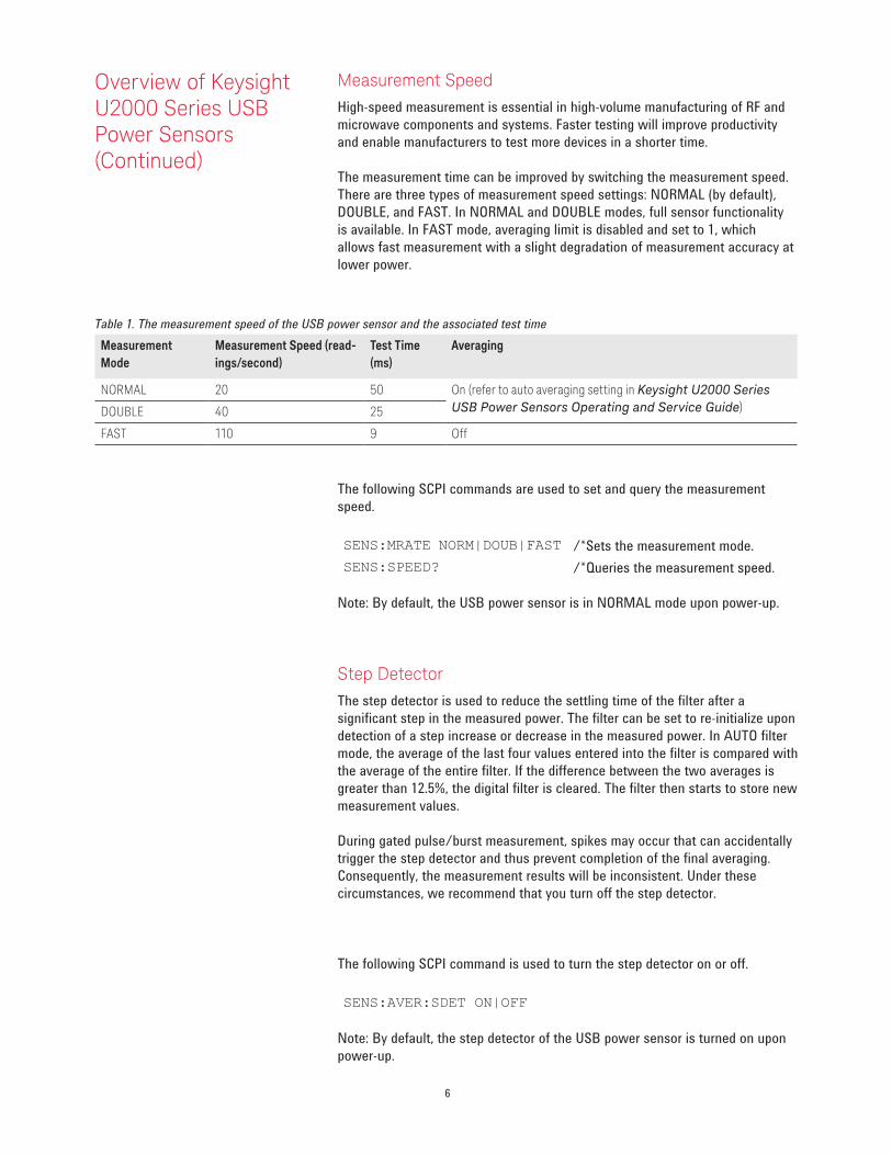
Measurement SpeedHigh-speed measurement is essential in high-volume manufacturing of RF and microwave components and systems. Faster testing will improve productivity and enable manufacturers to test more devices in a shorter time.
The measurement time can be improved by switching the measurement speed. There are three types of measurement speed settings: NORMAL (by default), DOUBLE, and FAST. In NORMAL and DOUBLE modes, full sensor functionality is available. In FAST mode, averaging limit is disabled and set to 1, which allows fast measurement with a slight degradation of measurement accuracy at lower power.
MeasurementMode
Measurement Speed (read-ings/second)
Test Time (ms)
Averaging
NORMAL 20 50 On (refer to auto averaging setting in Keysight U2000 Series USB Power Sensors Operating and Service Guide)DOUBLE 40 25
FAST 110 9 Off
The following SCPI commands are used to set and query the measurement speed.
SENS:MRATE NORM|DOUB|FAST /*Sets the measurement mode.SENS:SPEED? /*Queries the measurement speed.
Note: By default, the USB power sensor is in NORMAL mode upon power-up.
Step DetectorThe step detector is used to reduce the settling time of the filter after a significant step in the measured power. The filter can be set to re-initialize upon detection of a step increase or decrease in the measured power. In AUTO filter mode, the average of the last four values entered into the filter is compared with the average of the entire filter. If the difference between the two averages is greater than 12.5%, the digital filter is cleared. The filter then starts to store new measurement values.
During gated pulse/burst measurement, spikes may occur that can accidentally trigger the step detector and thus prevent completion of the final averaging. Consequently, the measurement results will be inconsistent. Under these circumstances, we recommend that you turn off the step detector.
The following SCPI command is used to turn the step detector on or off.
SENS:AVER:SDET ON|OFF
Note: By default, the step detector of the USB power sensor is turned on upon power-up.
Table 1. The measurement speed of the USB power sensor and the associated test time
Overview of Keysight U2000 Series USB Power Sensors (Continued)

7
Time-Gated Burst Power Measurement (External Triggering)
A recent firmware enhancement, version A.03.01 (and above), for the U2000 Series USB power sensor offers internal triggering capabilities in addition to the external trigger which is available since firmware version A.02.01. This feature allows you to set the gate offset and gate length and configure the USB power sensor in gated mode in order to perform the measurement.
The USB power sensor has a built-in trigger circuitry that controls the timing of a pulse-signal capture to enable measurement synchronization with an external instrument or event. An external signal greater than 1.9 V applied to the TRIG IN of the USB power sensor will trigger the power sensor to capture data.
As for the internal trigger, an adjustable measurement dependent threshold is used to define the trigger point of the signal being measured. This is especially useful for measuring pulses that do not occur at fixed intervals.
Figure 6. Simplified diagram for the setup of a time-gated burst power measurement (external triggering)
Figure 7. Diagram of a time-gated signal
Event 1
BNC-SMB cable
USB mini B cableKeysight USB
power sensorKeysight ESG/MXG Signal Source
TRIG IN
SENSe:SWEep:OFFSet:TIMEGate Offset
Trigger point
SENSe:SWEep:TIMEGate length:

8
The following table shows the sampling rate, maximum capture length, range settling time, dynamic range of the gated power measurements, and other specifications related to making time-gated measurement.
Table 2. Time-gated measurement specificationsParameters1 Performance
Maximum video bandwidth 40 kHzMinimum rise time 40 μsMinimum fall time 40 μsRabge settling time 150 μsMinimum pulse width 200 μsSampling rate 1.47 MspsMaximum capture length 150 msMaximum pulse repetition rate 150 kHzDynamic range U2000/1 /2A: –30 dBm to + 20 dBm
U2000/1 /2H: –10 dBm to + 30 dBmU2000/1B: 0 dBm to + 44 dBm
1. Not applicable for U2004A
Customer Application of GSM Power Amplifier (PA) Testing in Manufacturing
Figure 8 shows the testing of a GSM power amplifier module in one of the manufacturing sites. The signal generator produces a constant amplitude CW RF signal with a frequency sweep from 800 MHz to 2 GHz (GSM frequency range). The function generator generates a pulse with a 1/8 duty cycle into the GSM power amplifier module. The power amplifier module will be switched to GSM mode. The time-gated average power measurements (on the GSM timeslot) will be performed at the output of the amplifier module, after the attenuator, by using a Keysight USB power sensor. The USB power sensor is synchronizing with the function generator via an external triggering signal. This setup is done in production for fast tester measurement.
Figure 8. Simple setup diagram of GSM power amplifier module testing
Keysight 33220A function generator
Keysight N5183A MXG signal generator
Gain
GSM power amplifier module
Attenuator Keysight USB power sensor
USB mini B cable
PC/Laptop
Figure 9 shows another real-world example of using the USB power sensor with external trigger capability to measure the time-gated signal of the power amplifier module. Event 1 at the signal generator is used to synchronize or trigger the USB power sensor via TRIG IN before starting to capture the time-gated GSM signal (generated by the signal generator).
Pulse outputTRIG IN
Time-Gated Burst Power Measurement (External Triggering) (Continued)
Sync output

9
Keysight N5183A MXG signal generator
Gain
GSM power amplifier module
Attenuator Keysight USB power sensor
USB mini B cable
PC/Laptop
Attenuator
Figure 9: Simple setup diagram of time-gated burst power measurement (external triggering)
TRIG INEvent 1
Figure 10 depicts test setup when using the USB power sensor with internal trigger to measure the burst gated signal of a power amplifier module.
The following SCPI commands are used for CW measurement, used to measure the average power of the entire GSM waveform.
SYST:PRES /* Presets the instrument. SENS:FREQ 900MHZ /* Sets the frequency of testing.SENS:AVER:SDET OFF /* Turns off the step detector.SENS:DET:FUNC AVER
CALC:FEED “POW:AVER” /* Configures the measurement to CW mode.<Start time>
FETCH? /* Queries the measurement.<End time>
Note: The measurement time is calculated based on this equation: End time – Start time
Programming Examples
Keysight N5183A MXG signal generator
Gain
GSM power amplifier module
Attenuator Keysight USB power sensor
USB mini B cable
PC/Laptop
Attenuator
Figure 10: Simple setup for gated burst power measurement
TRIG IN
Customer Application of GSM Power Amplifier (PA) Testing in Manufacturing (Continued)

10
The following SCPI commands are used for time-gated burst power measurement of the GSM timeslot with external trigger.
SYST:PRES /* Presets the instrument. SENS:FREQ 900MHZ /* Sets the frequency of testing.SENS:AVER:SDET OFF /* Turns off the step detector.SENS:DET:FUNC NORM
TRIG:SOUR EXT /* Switches the trigger source to external.TRIG:SEQ:LEVEL -6dBm /* Sets the trigger level at -6dBm.SENS:SWEEP:TIME 0.000387 /* Configures the sweep time (gate length) of the burst duration (for
example: 387μs).SENS:SWEEP:OFFSET:TIME 0.00015 /* Configures the offset sweep time (offset length) of the burst duration
or delay between trigger point and time-gated period(for example: 150 μs).
CALC:FEED “POW:AVER ON SWEEP” /* Configures the measurement to gated mode.<Start time>
FETCH? /* Queries the measurement.<End time>
FETCH? /* Queries the measurement.<End time>
Note: The measurement time is calculated based on this equation: End time – Start time
The following SCPI commands are used for time-gated burst power measurement of the GSM timeslot with internal trigger.
SYST:PRES /* Presets the instrument. SENS:FREQ 900MHZ /* Sets the frequency of testing.SENS:AVER:SDET OFF /* Turns off the step detector.SENS:DET:FUNC NORM
TRIG:SOUR INT /* Switches the trigger source to internal.TRIG:SEQ:LEVEL -6dBm /* Sets the trigger level at -6dBm.SENS:SWEEP:TIME 0.000387 /* Configures the sweep time (gate length) of the burst duration (for example:
387μs).SENS:SWEEP:OFFSET:TIME 0.00015 /* Configures the offset sweep time (offset length) of the burst duration or delay
between trigger point and time-gated period(for example: 150 μs).
CALC:FEED “POW:AVER ON SWEEP” /* Configures the measurement to gated mode.<Start time>
FETCH? /* Queries the measurement.<End time>
Note: The measurement time is calculated based on this equation: End time – Start time
Programming Examples (Continued)

11
Conclusion Accurately measuring the average power of burst signals (within specific timeframes) is important for power amplifier module testing. It can be achieved not only with high-performance power meters and power sensors, but also with the low-cost Keysight USB power sensor. The trigger mechanisms offered by the USB power sensor allows you to measure the average burst signal accurately within the desired timeframe.
References – Fundamental of RF and Microwave Power Measurements (Part 1), Literature Number 5988-9213EN
– Fundamental of RF and Microwave Power Measurements (Part 2), Literature Number 5988-9214EN
– Fundamental of RF and Microwave Power Measurements (Part 3), Literature Number 5988-9215EN
– Fundamental of RF and Microwave Power Measurements (Part 4), Literature Number 5988-9216EN
– 4 Steps for Making Better Power Measurements, Literature Number 5989-8167EN
– Choosing the Right Power Meter and Sensors Product Note, Literature Number 5968-7150EN
Related Literature – Keysight U2000 Series USB Power Sensors Technical Overview, Literature Number: 5989-6279EN
– Keysight U2000 Series USB Power Sensors Data Sheet, Literature Number: 5989-6278EN
– Keysight U2000 Series USB Power Sensors Programming Guide, Part Number: U2000-90411
Related Link For the most up-to-date and complete application and product information, visit our product web site at: www.keysight.com/find/usbsensor.

For more information on Keysight Technologies’ products, applications or services, please contact your local Keysight office. The complete list is available at:www.keysight.com/find/contactus
Americas Canada (877) 894 4414Brazil 55 11 3351 7010Mexico 001 800 254 2440United States (800) 829 4444
Asia PacificAustralia 1 800 629 485China 800 810 0189Hong Kong 800 938 693India 1 800 112 929Japan 0120 (421) 345Korea 080 769 0800Malaysia 1 800 888 848Singapore 1 800 375 8100Taiwan 0800 047 866Other AP Countries (65) 6375 8100
Europe & Middle EastAustria 0800 001122Belgium 0800 58580Finland 0800 523252France 0805 980333Germany 0800 6270999Ireland 1800 832700Israel 1 809 343051Italy 800 599100Luxembourg +32 800 58580Netherlands 0800 0233200Russia 8800 5009286Spain 0800 000154Sweden 0200 882255Switzerland 0800 805353
Opt. 1 (DE)Opt. 2 (FR)Opt. 3 (IT)
United Kingdom 0800 0260637
For other unlisted countries:www.keysight.com/find/contactus(BP-07-10-14)
This information is subject to change without notice.© Keysight Technologies, 2010 - 2014Published in USA, July 31, 20145990-4447ENwww.keysight.com
12 | Keysight | U2000 Series USB Power Sensors - Technical Overview
myKeysight
www.keysight.com/find/mykeysightA personalized view into the information most relevant to you.
www.axiestandard.orgAdvancedTCA® Extensions for Instrumentation and Test (AXIe) is an open standard that extends the AdvancedTCA for general purpose and semiconductor test. Keysight is a founding member of the AXIe consortium. ATCA®, AdvancedTCA®, and the ATCA logo are registered US trademarks of the PCI Industrial Computer Manufacturers Group.
www.lxistandard.org
LAN eXtensions for Instruments puts the power of Ethernet and the Web inside your test systems. Keysight is a founding member of the LXI consortium.
www.pxisa.org
PCI eXtensions for Instrumentation (PXI) modular instrumentation delivers a rugged, PC-based high-performance measurement and automation system.
Three-Year Warranty
www.keysight.com/find/ThreeYearWarrantyKeysight’s commitment to superior product quality and lower total cost of ownership. The only test and measurement company with three-year warranty standard on all instruments, worldwide.
Keysight Assurance Planswww.keysight.com/find/AssurancePlansUp to five years of protection and no budgetary surprises to ensure your instruments are operating to specification so you can rely on accurate measurements.
www.keysight.com/qualityKeysight Technologies, Inc.DEKRA Certified ISO 9001:2008 Quality Management System
Keysight Channel Partnerswww.keysight.com/find/channelpartnersGet the best of both worlds: Keysight’s measurement expertise and product breadth, combined with channel partner convenience.
www.keysight.com/find/usbsensor