Embed Size (px)
Citation preview
Keysight U2741A USB Modular 5.5 Digits Digital Multimeter
Service Guide
2 Keysight U2741A Service Guide
NoticesCopyright Notice© Keysight Technologies 2008 - 2017No part of this manual may be reproduced in any form or by any means (including electronic storage and retrieval or translation into a foreign language) without prior agreement and written consent from Keysight Technologies as governed by United States and international copyright laws.
Manual Part NumberU2741-90012
EditionEdition 5, March 17, 2017
Printed in:Printed in Malaysia
Published by:Keysight Technologies Bayan Lepas Free Industrial Zone, 11900 Penang, Malaysia
Technology Licenses The hardware and/or software described in this document are furnished under a license and may be used or copied only in accordance with the terms of such license.
Declaration of ConformityDeclarations of Conformity for this product and for other Keysight products may be downloaded from the Web. Go to http://www.keysight.com/go/conformity. You can then search by product number to find the latest Declaration of Conformity.
U.S. Government RightsThe Software is “commercial computer software,” as defined by Federal Acquisition Regulation (“FAR”) 2.101. Pursuant to FAR 12.212 and 27.405-3 and Department of Defense FAR Supplement (“DFARS”) 227.7202, the U.S. government acquires commercial computer software under the same terms by which the software is customarily provided to the public. Accordingly, Keysight provides the Software to U.S. government customers under its standard commercial license, which is embodied in its End User License Agreement (EULA), a copy of which can be found at http://www.keysight.com/find/sweula. The license set forth in the EULA represents the exclusive authority by which the U.S. government may use, modify, distribute, or disclose the Software. The EULA and the license set forth therein, does not require or permit, among other things, that Keysight: (1) Furnish technical information related to commercial computer software or commercial computer software documentation that is not customarily provided to the public; or (2) Relinquish to, or otherwise provide, the government rights in excess of these rights customarily provided to the public to use, modify, reproduce, release, perform, display, or disclose commercial computer software or commercial computer software documentation. No additional government requirements beyond those set forth in the EULA shall apply, except to the extent that those terms, rights, or licenses are explicitly required from all providers of commercial computer software pursuant to the FAR and the DFARS and are set forth specifically in writing elsewhere in the EULA. Keysight shall be under no obligation to update, revise or otherwise modify the Software. With respect to any technical data as defined by FAR 2.101, pursuant to FAR 12.211 and 27.404.2 and DFARS 227.7102, the U.S. government acquires no greater than Limited Rights as defined in FAR 27.401 or DFAR 227.7103-5 (c), as applicable in any technical data.
WarrantyTHE MATERIAL CONTAINED IN THIS DOCUMENT IS PROVIDED “AS IS,” AND IS SUBJECT TO BEING CHANGED, WITHOUT NOTICE, IN FUTURE EDITIONS. FURTHER, TO THE MAXIMUM EXTENT PERMITTED BY APPLICABLE LAW, KEYSIGHT DISCLAIMS ALL WARRANTIES, EITHER EXPRESS OR IMPLIED, WITH REGARD TO THIS MANUAL AND ANY INFORMATION CONTAINED HEREIN, INCLUDING BUT NOT LIMITED TO THE IMPLIED WARRANTIES OF MERCHANTABILITY AND FITNESS FOR A PARTICULAR PURPOSE. KEYSIGHT SHALL NOT BE LIABLE FOR ERRORS OR FOR INCIDENTAL OR CONSEQUENTIAL DAMAGES IN CONNECTION WITH THE FURNISHING, USE, OR PERFORMANCE OF THIS DOCUMENT OR OF ANY INFORMATION CONTAINED HEREIN. SHOULD KEYSIGHT AND THE USER HAVE A SEPARATE WRITTEN AGREEMENT WITH WARRANTY TERMS COVERING THE MATERIAL IN THIS DOCUMENT THAT CONFLICT WITH THESE TERMS, THE WARRANTY TERMS IN THE SEPARATE AGREEMENT SHALL CONTROL.
Safety Information
CAUTIONA CAUTION notice denotes a hazard. It calls attention to an operating procedure, practice, or the like that, if not correctly performed or adhered to, could result in damage to the product or loss of important data. Do not proceed beyond a CAUTION notice until the indicated conditions are fully understood and met.
WARNINGA WARNING notice denotes a hazard. It calls attention to an operating procedure, practice, or the like that, if not correctly performed or adhered to, could result in personal injury or death. Do not proceed beyond a WARNING notice until the indicated conditions are fully understood and met.
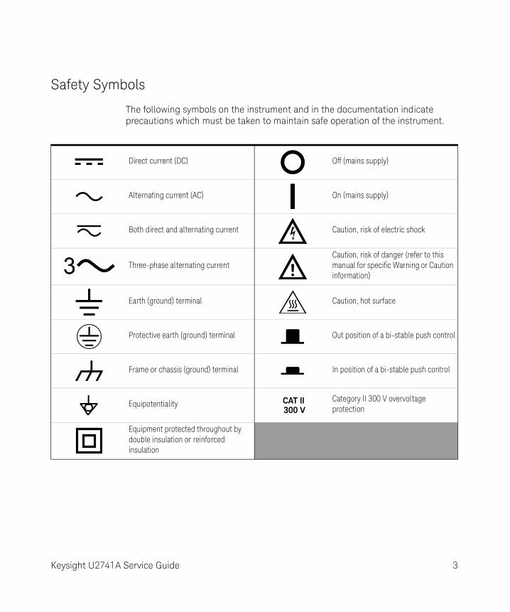
Safety Symbols
The following symbols on the instrument and in the documentation indicate precautions which must be taken to maintain safe operation of the instrument.
Direct current (DC) Off (mains supply)
Alternating current (AC) On (mains supply)
Both direct and alternating current Caution, risk of electric shock
Three-phase alternating currentCaution, risk of danger (refer to this manual for specific Warning or Caution information)
Earth (ground) terminal Caution, hot surface
Protective earth (ground) terminal Out position of a bi-stable push control
Frame or chassis (ground) terminal In position of a bi-stable push control
EquipotentialityCategory II 300 V overvoltage protection
Equipment protected throughout by double insulation or reinforced insulation
CAT II300 V
Keysight U2741A Service Guide 3
General Safety Information
WARNING– Do not use the device if it is damaged. Before you use the device, inspect
the casing. Look for cracks or missing plastic. Do not operate the device around explosive gas, vapor, or dust.
– Always use the device with the cables provided.
– Observe all markings on the device before establishing any connection.
– Turn off the device and application system power before connecting to the I/O terminals.
– When servicing the device, use only the specified replacement parts.
– Do not operate the device with the cover removed or loosened.
– Use only the power adapter provided by the manufacturer to avoid any unexpected hazards.
CAUTION– If the device is used in a manner not specified by the manufacturer, the
device protection may be impaired.
– Always use dry cloth to clean the device. Do not use ethyl alcohol or any other volatile liquid to clean the device.
– Do not permit any blockage of the ventilation holes of the device.
4 Keysight U2741A Service Guide
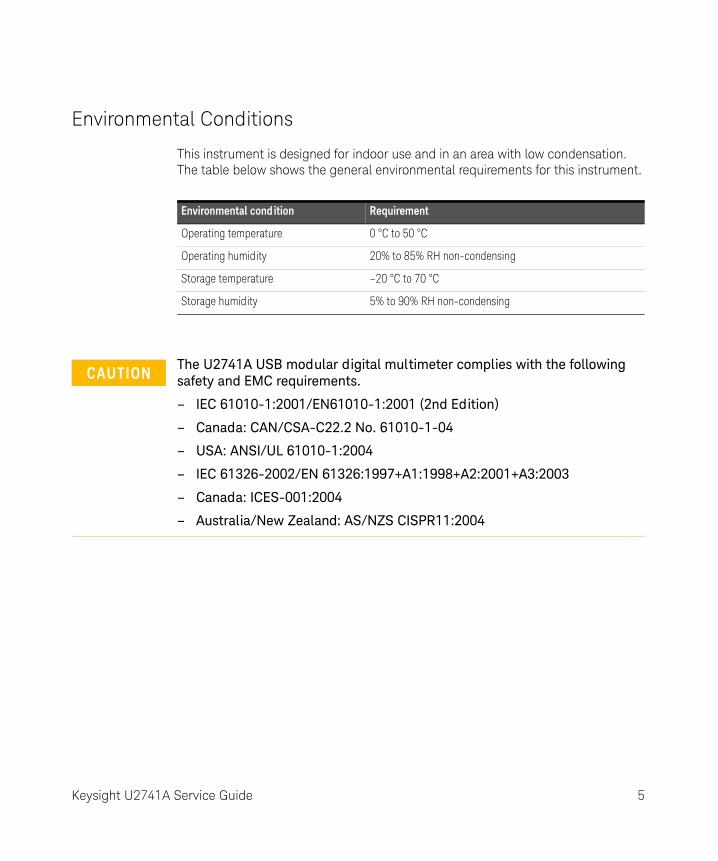
Environmental Conditions
This instrument is designed for indoor use and in an area with low condensation. The table below shows the general environmental requirements for this instrument.
Environmental cond ition Requirement
Operating temperature 0 °C to 50 °C
Operating humidity 20% to 85% RH non-condensing
Storage temperature –20 °C to 70 °C
Storage humidity 5% to 90% RH non-condensing
CAUTIONThe U2741A USB modular digital multimeter complies with the following safety and EMC requirements.
– IEC 61010-1:2001/EN61010-1:2001 (2nd Edition)
– Canada: CAN/CSA-C22.2 No. 61010-1-04
– USA: ANSI/UL 61010-1:2004
– IEC 61326-2002/EN 61326:1997+A1:1998+A2:2001+A3:2003
– Canada: ICES-001:2004
– Australia/New Zealand: AS/NZS CISPR11:2004
Keysight U2741A Service Guide 5
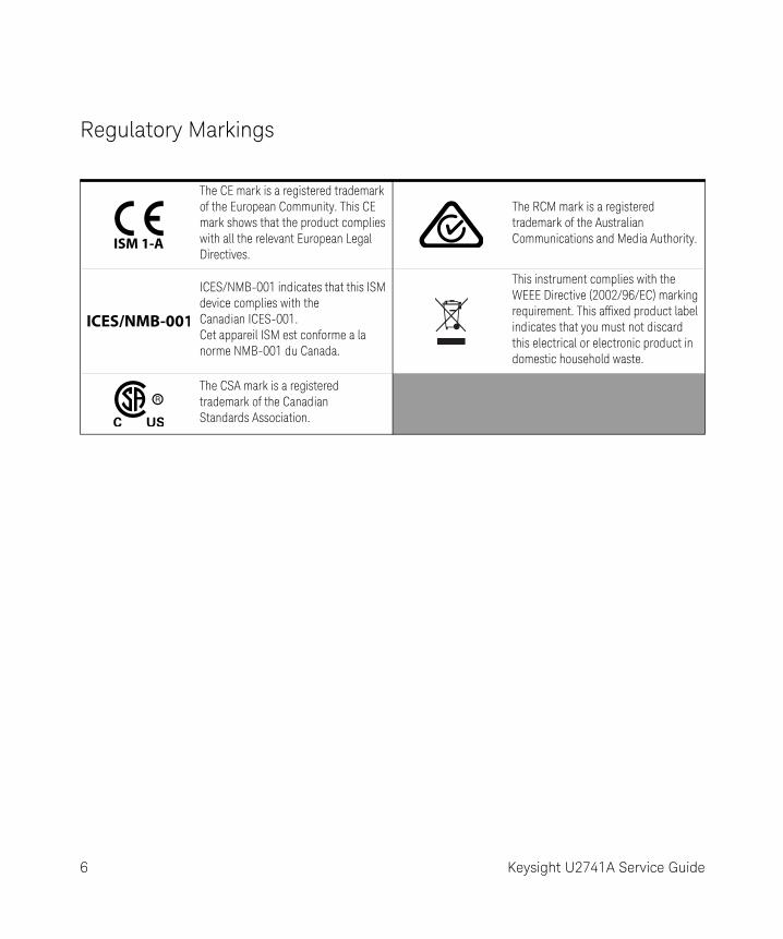
Regulatory Markings
The CE mark is a registered trademark of the European Community. This CE mark shows that the product complies with all the relevant European Legal Directives.
The RCM mark is a registered trademark of the Australian Communications and Media Authority.
ICES/NMB-001 indicates that this ISM device complies with the Canadian ICES-001. Cet appareil ISM est conforme a la norme NMB-001 du Canada.
This instrument complies with the WEEE Directive (2002/96/EC) marking requirement. This affixed product label indicates that you must not discard this electrical or electronic product in domestic household waste.
The CSA mark is a registered trademark of the Canadian Standards Association.
6 Keysight U2741A Service Guide
Waste Electrical and Electronic Equipment (WEEE) Directive 2002/96/EC
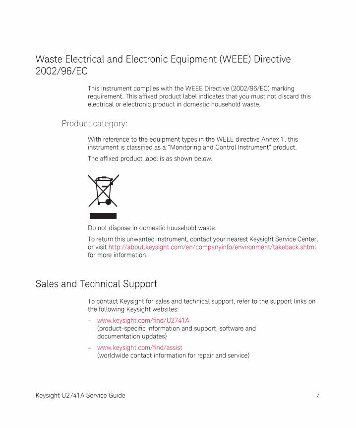
This instrument complies with the WEEE Directive (2002/96/EC) marking requirement. This affixed product label indicates that you must not discard this electrical or electronic product in domestic household waste.
Product category:
With reference to the equipment types in the WEEE directive Annex 1, this instrument is classified as a “Monitoring and Control Instrument” product.
The affixed product label is as shown below.
Do not dispose in domestic household waste.
To return this unwanted instrument, contact your nearest Keysight Service Center, or visit http://about.keysight.com/en/companyinfo/environment/takeback.shtml for more information.
Sales and Technical Support
To contact Keysight for sales and technical support, refer to the support links on the following Keysight websites:
– www.keysight.com/find/U2741A (product-specific information and support, software and documentation updates)
– www.keysight.com/find/assist (worldwide contact information for repair and service)
Keysight U2741A Service Guide 7

THIS PAGE HAS BEEN INTENTIONALLY LEFT BLANK.
8 Keysight U2741A Service Guide
Table of Contents
Safety Symbols . . . . . . . . . . . . . . . . . . . . . . . . . . . . . . . . . . . . . . . . . . . . .3General Safety Information . . . . . . . . . . . . . . . . . . . . . . . . . . . . . . . . . . . .4Environmental Conditions . . . . . . . . . . . . . . . . . . . . . . . . . . . . . . . . . . . .5Regulatory Markings . . . . . . . . . . . . . . . . . . . . . . . . . . . . . . . . . . . . . . . . .6Waste Electrical and Electronic Equipment (WEEE) Directive
2002/96/EC . . . . . . . . . . . . . . . . . . . . . . . . . . . . . . . . . . . . . . . . . . . . .7Product category: . . . . . . . . . . . . . . . . . . . . . . . . . . . . . . . . . . . . . . . .7
Sales and Technical Support . . . . . . . . . . . . . . . . . . . . . . . . . . . . . . . . . .7
1 Characteristics and Specifications
2 Performance Test Calibration
Calibration Overview . . . . . . . . . . . . . . . . . . . . . . . . . . . . . . . . . . . . . . . .16Closed - case electronic calibration . . . . . . . . . . . . . . . . . . . . . . . . .16Keysight technologies calibration services . . . . . . . . . . . . . . . . . . . .16Calibration interval . . . . . . . . . . . . . . . . . . . . . . . . . . . . . . . . . . . . . . .17Time required for calibration . . . . . . . . . . . . . . . . . . . . . . . . . . . . . . .17
Recommended Test Equipment . . . . . . . . . . . . . . . . . . . . . . . . . . . . . . .18Self-Calibration . . . . . . . . . . . . . . . . . . . . . . . . . . . . . . . . . . . . . . . . . . . .19Test Considerations . . . . . . . . . . . . . . . . . . . . . . . . . . . . . . . . . . . . . . . .20
Input connections . . . . . . . . . . . . . . . . . . . . . . . . . . . . . . . . . . . . . . .20Performance Verification Tests Overview . . . . . . . . . . . . . . . . . . . . . . . .21Performance Verification Tests . . . . . . . . . . . . . . . . . . . . . . . . . . . . . . . .22
Zero offset verification . . . . . . . . . . . . . . . . . . . . . . . . . . . . . . . . . . . .22Gain verification . . . . . . . . . . . . . . . . . . . . . . . . . . . . . . . . . . . . . . . . .24AC voltage verification test . . . . . . . . . . . . . . . . . . . . . . . . . . . . . . . .28AC current verification test . . . . . . . . . . . . . . . . . . . . . . . . . . . . . . . .29Optional AC voltage performance verification test . . . . . . . . . . . . . .31Optional AC current performance verification test . . . . . . . . . . . . . .32
Keysight U2741A Service Guide 9
3 Service
Types of Service Available . . . . . . . . . . . . . . . . . . . . . . . . . . . . . . . . . . . 34Extended service contracts . . . . . . . . . . . . . . . . . . . . . . . . . . . . . . . . 34Obtaining repair service (Worldwide) . . . . . . . . . . . . . . . . . . . . . . . . 34
Repackaging for Shipment . . . . . . . . . . . . . . . . . . . . . . . . . . . . . . . . . . 35Cleaning . . . . . . . . . . . . . . . . . . . . . . . . . . . . . . . . . . . . . . . . . . . . . . . . . 36Electrostatic Discharge (ESD) Precautions . . . . . . . . . . . . . . . . . . . . . . 37To Replace a Current Input Fuse . . . . . . . . . . . . . . . . . . . . . . . . . . . . . . 38Troubleshooting the modular DMM . . . . . . . . . . . . . . . . . . . . . . . . . . . . 39
4 Replacement Parts
To Order Replaceable Parts . . . . . . . . . . . . . . . . . . . . . . . . . . . . . . . . . . 42General Disassemble . . . . . . . . . . . . . . . . . . . . . . . . . . . . . . . . . . . . . . . 43
10 Keysight U2741A Service Guide
List of Tables
Table 2-1 Recommended test equipment . . . . . . . . . . . . . . . . . .18Table 2-2 Zero offset verification test . . . . . . . . . . . . . . . . . . . . .22Table 2-3 DC voltage gain verification . . . . . . . . . . . . . . . . . . . . .24Table 2-4 DC current gain verification . . . . . . . . . . . . . . . . . . . . .25Table 2-5 Ohms gain verification test . . . . . . . . . . . . . . . . . . . . .26Table 2-6 Frequency gain verification test . . . . . . . . . . . . . . . . . .27Table 2-7 AC volts verification test error . . . . . . . . . . . . . . . . . . .28Table 2-8 AC current verification test . . . . . . . . . . . . . . . . . . . . .30Table 2-9 Optional AC voltage performance verification test . . .31Table 2-10 Optional AC current performance verification test . . .32Table 4-1 List of replacement parts . . . . . . . . . . . . . . . . . . . . . . .42
Keysight U2741A Service Guide 11

THIS PAGE HAS BEEN INTENTIONALLY LEFT BLANK.
12 Keysight U2741A Service Guide
Keysight U2741A USB Modular 5.5 Digits Digital MultimeterService Guide
1 Characteristics and Specifications
For the characteristics and specifications of the U2741A USB Modular 5.5 Digits Digital Multimeter, refer to the datasheet at http://literature.cdn.keysight.com/litweb/pdf/5991-0042EN.pdf.
13

1 Characteristics and Specifications
THIS PAGE HAS BEEN INTENTIONALLY LEFT BLANK.
14 Keysight U2741A Service Guide
Keysight U2741A USB Modular 5.5 Digits Digital MultimeterService Guide
2 Performance Test Calibration
Calibration Overview 16Recommended Test Equipment 18Self-Calibration 19Test Considerations 20Performance Verification Tests Overview 21Performance Verification Tests 22
This chapter contains performance test and calibration procedures. The performance tests procedures allow you to verify that the multimeter is operating within its published specifications.
15
2 Performance Test Calibration
Calibration Overview
Closed-case electronic calibration
The instrument features a closed-case electronic calibration. No internal mechanical adjustments are required. The instrument calculates the correction factors based upon the input reference value that you set. The new correction factors are stored in nonvolatile memory until the next calibration adjustment is performed. The nonvolatile EEPROM calibration memory does not change when power has been off or after a remote interface reset.
Keysight technologies calibration services
When your instrument is due for calibration, contact your local Keysight Service Center for a low-cost recalibration. The U2741A is supported on automated calibration systems, which allows Keysight to provide this service at competitive prices.
WARNINGSHOCK HAZARD. Only service trained personnels who are aware of the hazards involved should perform the procedure in this chapter. To avoid electrical shock and personal injury, make sure to read and follow all test equipments safety instructions.
NOTEMake sure you have read “Test Considerations” on page 20 before calibrating the instrument.
16 Keysight U2741A Service Guide
Performance Test Calibration 2
Calibration interval
A one year interval is adequate for most applications. Accuracy specifications are warranted only if adjustment is made at regular calibration intervals. Accuracy specifications are not warranted beyond the one year calibration interval. Keysight does not recommend extending calibration intervals beyond two years for any application.
Time required for calibration
The U2741A can be automatically calibrated under computer control. With computer control, you can perform the complete calibration procedure and performance verification tests in less than 30 minutes once the instrument is warmed-up (see “Test Considerations” on page 20). Refer to the U2741A Programmer's Reference Guide for more information.
Keysight U2741A Service Guide 17
2 Performance Test Calibration
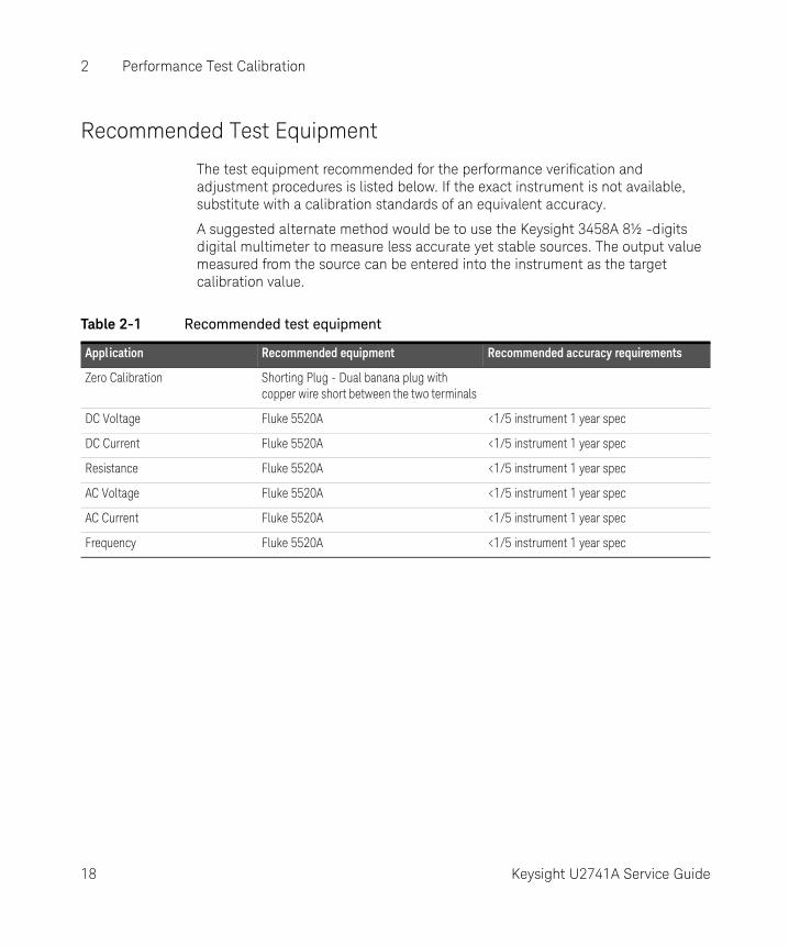
Recommended Test Equipment
The test equipment recommended for the performance verification and adjustment procedures is listed below. If the exact instrument is not available, substitute with a calibration standards of an equivalent accuracy.
A suggested alternate method would be to use the Keysight 3458A 8½ -digits digital multimeter to measure less accurate yet stable sources. The output value measured from the source can be entered into the instrument as the target calibration value.
Table 2-1 Recommended test equipment
Application Recommended equipment Recommended accuracy requirements
Zero Calibration Shorting Plug - Dual banana plug with copper wire short between the two terminals
DC Voltage Fluke 5520A <1/5 instrument 1 year spec
DC Current Fluke 5520A <1/5 instrument 1 year spec
Resistance Fluke 5520A <1/5 instrument 1 year spec
AC Voltage Fluke 5520A <1/5 instrument 1 year spec
AC Current Fluke 5520A <1/5 instrument 1 year spec
Frequency Fluke 5520A <1/5 instrument 1 year spec
18 Keysight U2741A Service Guide
Performance Test Calibration 2
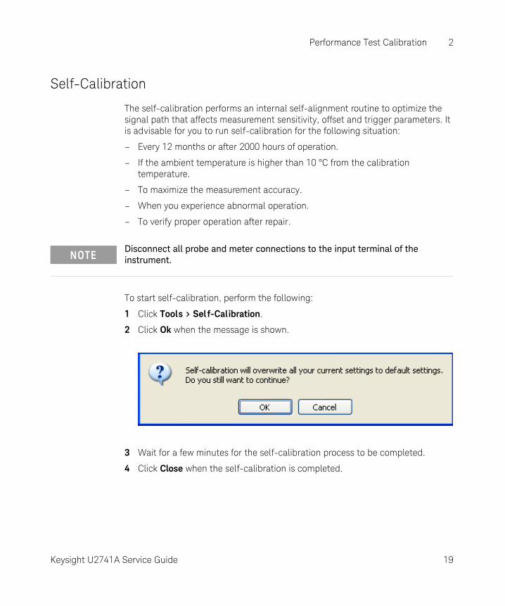
Self-Calibration
The self-calibration performs an internal self-alignment routine to optimize the signal path that affects measurement sensitivity, offset and trigger parameters. It is advisable for you to run self-calibration for the following situation:
– Every 12 months or after 2000 hours of operation.
– If the ambient temperature is higher than 10 °C from the calibration temperature.
– To maximize the measurement accuracy.
– When you experience abnormal operation.
– To verify proper operation after repair.
To start self-calibration, perform the following:
1 Click Tools > Sel f-Calibration.
2 Click Ok when the message is shown.
3 Wait for a few minutes for the self-calibration process to be completed.
4 Click Close when the self-calibration is completed.
NOTEDisconnect all probe and meter connections to the input terminal of the instrument.
Keysight U2741A Service Guide 19
2 Performance Test Calibration
Test Considerations
Errors may be induced by AC signals present on the input leads during the verification tests. Long test leads can also act as an antenna causing pick-up of AC signals.
For optimum performance, all procedures should comply with the following recommendations:
– Ensure that the calibration ambient temperature is stable and in between 18 °C and 28 °C. Ideally the calibration should be performed at 23 °C ±1 °C.
– Ensure that the ambient relative humidity is less than 80%.
– Allow a one hour warm-up period with a Shorting Plug connected to the HI and LO input terminals.
– Use shielded twisted pair PTFE-insulated cables to reduce settling and noise errors. Keep the input cables as short as possible.
– Connect the input cable shields to the ground. Except where noted in the procedures, connect the calibrator LO source to the ground at the calibrator. It is important that the LO to the ground connection be made at only one place in the circuit to avoid ground loops.
As the instrument is capable of making very accurate measurements, you must take special care to ensure that the calibration standards and test procedures used do not introduce additional errors. Ideally, the standards used to verify and adjust the instrument should be an order of magnitude more accurate than each instrument range full-scale error specification.
For the DC voltage, DC current and resistance gain verification measurements, you should ensure the calibrator's “0” output is correct. You will need to set the offset for each range of the measuring function being verified.
Input connections
Test connections to the instrument are best accomplished using the dual banana plug with a copper wire short between two terminals for low-thermal offset measurement. Shielded, twisted-pair, PTFE interconnect cables of a minimum length are recommended between the calibrator and the multimeter. Cable shields should be earth ground referenced. This configuration is recommended for optimal noises and settling time performance during calibration.
20 Keysight U2741A Service Guide
Performance Test Calibration 2
Performance Verification Tests Overview
Use the Performance Verification Tests to verify the measurement performance of the instrument. The performance verification tests use the instrument's specifications listed in Chapter 1, “Characteristics and Specifications”.
You can perform four different levels of performance verification tests:
Quick verification
A selected verification test.
Performance verification tests
An extensive set of tests that are recommended as an acceptance test when you first receive the instrument or after performing adjustments.
Optional verification tests
Tests that are not performed with every calibration. Perform these tests to verify additional specifications or functions of the instrument.
Quick performance check
The quick performance check is an abbreviated performance test (specified by the letter Q in the performance verification tests). This test provides a simple method to achieve high confidence in the instrument's ability to functionally operate and meet specifications. These tests represent the absolute minimum set of performance checks recommended following any service activity. Auditing the instrument's performance for the quick check points (designated by a Q) verifies performance for “normal” accuracy drift mechanisms. This test does not check for abnormal component failures.
To do a quick performance check, carry out only the performance verification tests indicated in the following tables with the letter Q.
If the instrument fails the quick performance check, adjustment or repair is required.
Adjustment is recommended at every calibration interval. If adjustment is not made, you must establish a ‘guard band’, using no more than 80% of the specifications, as the verification limits.
NOTEMake sure you have read “Test Considerations” on page 20 before doing the performance verification tests.
Keysight U2741A Service Guide 21
2 Performance Test Calibration
Performance Verification Tests
Zero offset verification
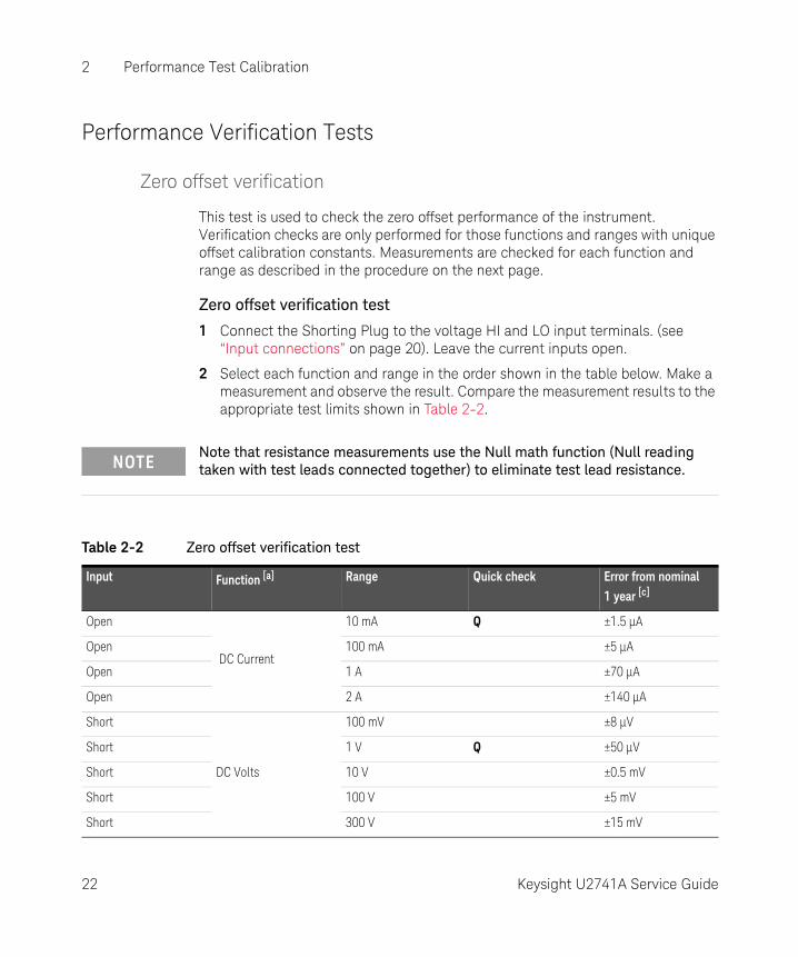
This test is used to check the zero offset performance of the instrument. Verification checks are only performed for those functions and ranges with unique offset calibration constants. Measurements are checked for each function and range as described in the procedure on the next page.
Zero offset verification test
1 Connect the Shorting Plug to the voltage HI and LO input terminals. (see “Input connections” on page 20). Leave the current inputs open.
2 Select each function and range in the order shown in the table below. Make a measurement and observe the result. Compare the measurement results to the appropriate test limits shown in Table 2-2.
NOTENote that resistance measurements use the Null math function (Null reading taken with test leads connected together) to eliminate test lead resistance.
Table 2-2 Zero offset verification test
Input Function [a] Range Quick check Error from nominal 1 year [c]
Open
DC Current
10 mA Q ±1.5 µA
Open 100 mA ±5 µA
Open 1 A ±70 µA
Open 2 A ±140 µA
Short
DC Volts
100 mV ±8 µV
Short 1 V Q ±50 µV
Short 10 V ±0.5 mV
Short 100 V ±5 mV
Short 300 V ±15 mV
22 Keysight U2741A Service Guide
Performance Test Calibration 2
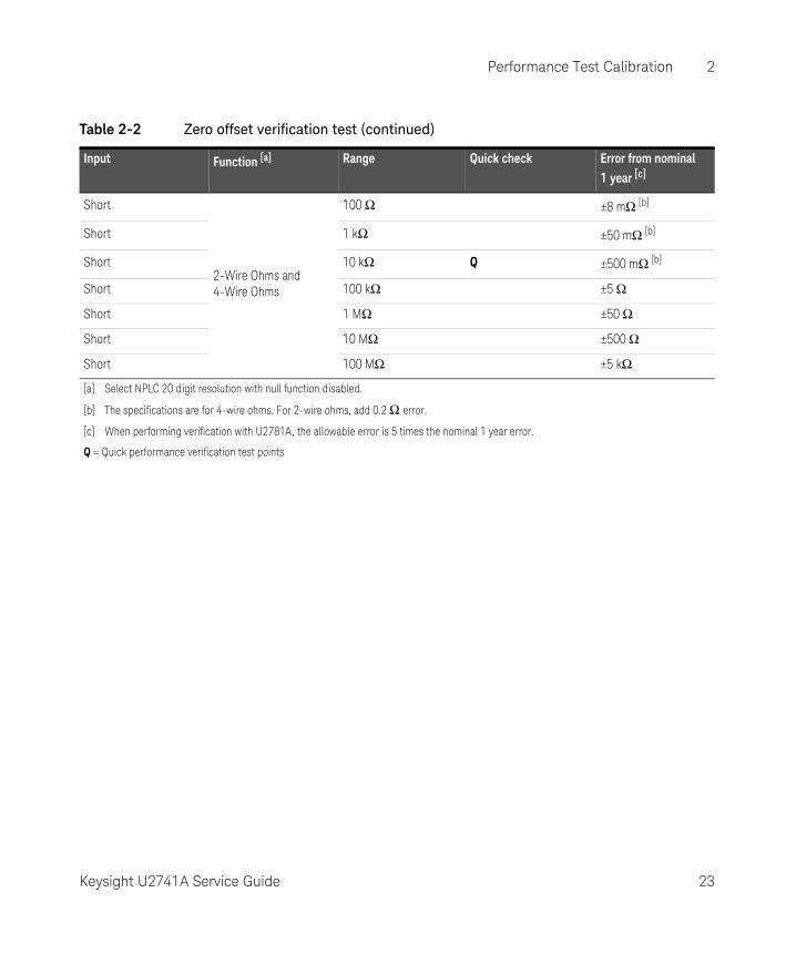
Short
2-Wire Ohms and 4-Wire Ohms
100 Ω ±8 mΩ [b]
Short 1 kΩ ±50 mΩ [b]
Short 10 kΩ Q ±500 mΩ [b]
Short 100 kΩ ±5 Ω
Short 1 MΩ ±50 Ω
Short 10 MΩ ±500 Ω
Short 100 MΩ ±5 kΩ
[a] Select NPLC 20 digit resolution with null function disabled.
[b] The specifications are for 4-wire ohms. For 2-wire ohms, add 0.2 Ω error.
[c] When performing verification with U2781A, the allowable error is 5 times the nominal 1 year error.
Q = Quick performance verification test points
Table 2-2 Zero offset verification test (continued)
Input Function [a] Range Quick check Error from nominal 1 year [c]
Keysight U2741A Service Guide 23
2 Performance Test Calibration
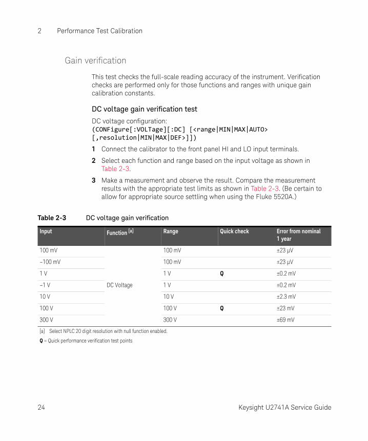
Gain verification
This test checks the full-scale reading accuracy of the instrument. Verification checks are performed only for those functions and ranges with unique gain calibration constants.
DC voltage gain verification test
DC voltage configuration: (CONFigure[:VOLTage][:DC] [<range|MIN|MAX|AUTO> [,resolution|MIN|MAX|DEF>]])
1 Connect the calibrator to the front panel HI and LO input terminals.
2 Select each function and range based on the input voltage as shown in Table 2-3.
3 Make a measurement and observe the result. Compare the measurement results with the appropriate test limits as shown in Table 2-3. (Be certain to allow for appropriate source settling when using the Fluke 5520A.)
Table 2-3 DC voltage gain verification
Input Function [a] Range Quick check Error from nominal 1 year
100 mV
DC Voltage
100 mV ±23 µV
–100 mV 100 mV ±23 µV
1 V 1 V Q ±0.2 mV
–1 V 1 V ±0.2 mV
10 V 10 V ±2.3 mV
100 V 100 V Q ±23 mV
300 V 300 V ±69 mV
[a] Select NPLC 20 digit resolution with null function enabled.
Q = Quick performance verification test points
24 Keysight U2741A Service Guide
Performance Test Calibration 2
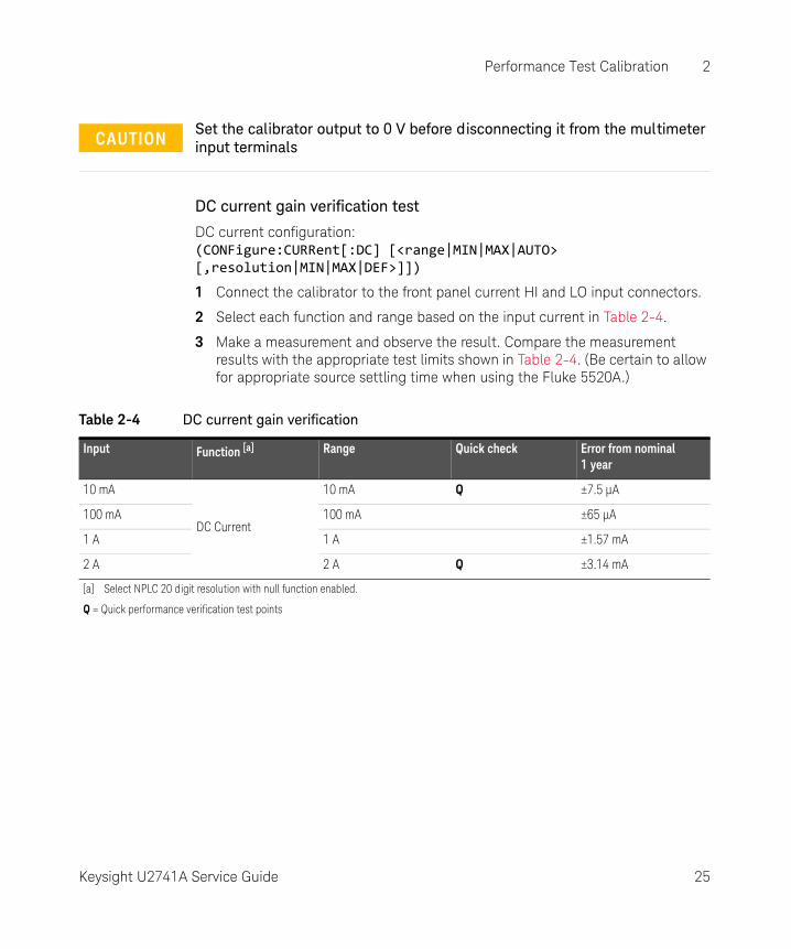
DC current gain verification test
DC current configuration: (CONFigure:CURRent[:DC] [<range|MIN|MAX|AUTO> [,resolution|MIN|MAX|DEF>]])
1 Connect the calibrator to the front panel current HI and LO input connectors.
2 Select each function and range based on the input current in Table 2-4.
3 Make a measurement and observe the result. Compare the measurement results with the appropriate test limits shown in Table 2-4. (Be certain to allow for appropriate source settling time when using the Fluke 5520A.)
CAUTIONSet the calibrator output to 0 V before disconnecting it from the multimeter input terminals
Table 2-4 DC current gain verification
Input Function [a] Range Quick check Error from nominal 1 year
10 mA
DC Current
10 mA Q ±7.5 µA
100 mA 100 mA ±65 µA
1 A 1 A ±1.57 mA
2 A 2 A Q ±3.14 mA
[a] Select NPLC 20 digit resolution with null function enabled.
Q = Quick performance verification test points
Keysight U2741A Service Guide 25
2 Performance Test Calibration
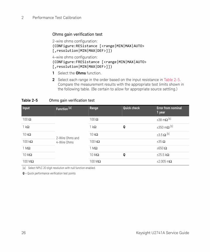
Ohms gain verification test
2-wire ohms configuration: (CONFigure:RESistance [<range|MIN|MAX|AUTO> [,resolution|MIN|MAX|DEF>]])
4-wire ohms configuration: (CONFigure:FRESistance [<range|MIN|MAX|AUTO> [,resolution|MIN|MAX|DEF>]])
1 Select the Ohms function.
2 Select each range in the order based on the input resistance in Table 2-5. Compare the measurement results with the appropriate test limits shown in the following table. (Be certain to allow for appropriate source settling.)
Table 2-5 Ohms gain verification test
Input Function [a] Range Quick check Error from nominal 1 year
100 Ω
2-Wire Ohms and 4-Wire Ohms
100 Ω ±38 mΩ [b]
1 kΩ 1 kΩ Q ±350 mΩ [b]
10 kΩ 10 kΩ ±3.5 Ω [b]
100 kΩ 100 kΩ ±35 Ω
1 MΩ 1 MΩ ±650 Ω
10 MΩ 10 MΩ Q ±25.5 kΩ
100 MΩ 100 MΩ ±2.005 mΩ
[a] Select NPLC 20 digit resolution with null function enabled.
Q = Quick performance verification test points
26 Keysight U2741A Service Guide
Performance Test Calibration 2
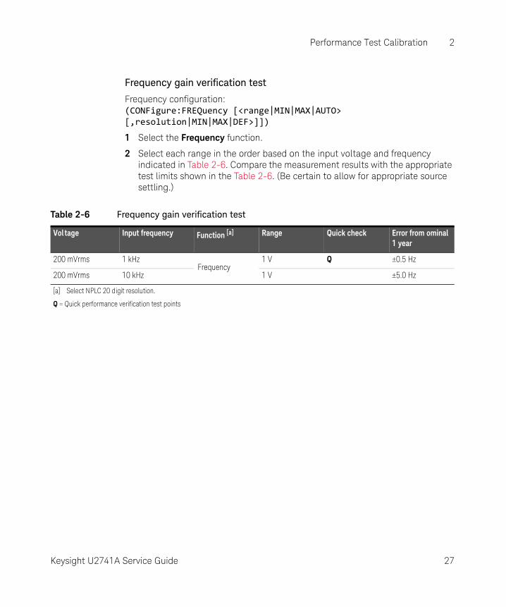
Frequency gain verification test
Frequency configuration: (CONFigure:FREQuency [<range|MIN|MAX|AUTO> [,resolution|MIN|MAX|DEF>]])
1 Select the Frequency function.
2 Select each range in the order based on the input voltage and frequency indicated in Table 2-6. Compare the measurement results with the appropriate test limits shown in the Table 2-6. (Be certain to allow for appropriate source settling.)
Table 2-6 Frequency gain verification test
Voltage Input frequency Function [a] Range Quick check Error from ominal 1 year
200 mVrms 1 kHzFrequency
1 V Q ±0.5 Hz
200 mVrms 10 kHz 1 V ±5.0 Hz
[a] Select NPLC 20 digit resolution.
Q = Quick performance verification test points
Keysight U2741A Service Guide 27
2 Performance Test Calibration
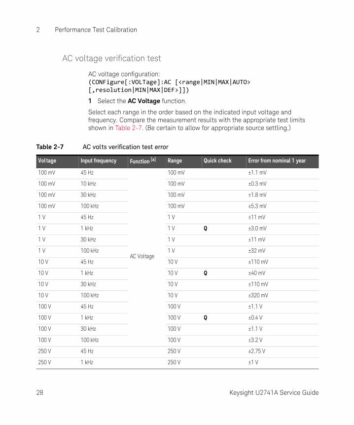
AC voltage verification test
AC voltage configuration: (CONFigure[:VOLTage]:AC [<range|MIN|MAX|AUTO> [,resolution|MIN|MAX|DEF>]])
1 Select the AC Voltage function.
Select each range in the order based on the indicated input voltage and frequency. Compare the measurement results with the appropriate test limits shown in Table 2-7. (Be certain to allow for appropriate source settling.)
Table 2-7 AC volts verification test error
Vol tage Input frequency Function [a] Range Quick check Error from nominal 1 year
100 mV 45 Hz
AC Voltage
100 mV ±1.1 mV
100 mV 10 kHz 100 mV ±0.3 mV
100 mV 30 kHz 100 mV ±1.8 mV
100 mV 100 kHz 100 mV ±5.3 mV
1 V 45 Hz 1 V ±11 mV
1 V 1 kHz 1 V Q ±3.0 mV
1 V 30 kHz 1 V ±11 mV
1 V 100 kHz 1 V ±32 mV
10 V 45 Hz 10 V ±110 mV
10 V 1 kHz 10 V Q ±40 mV
10 V 30 kHz 10 V ±110 mV
10 V 100 kHz 10 V ±320 mV
100 V 45 Hz 100 V ±1.1 V
100 V 1 kHz 100 V Q ±0.4 V
100 V 30 kHz 100 V ±1.1 V
100 V 100 kHz 100 V ±3.2 V
250 V 45 Hz 250 V ±2.75 V
250 V 1 kHz 250 V ±1 V
28 Keysight U2741A Service Guide
Performance Test Calibration 2
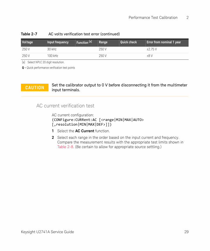
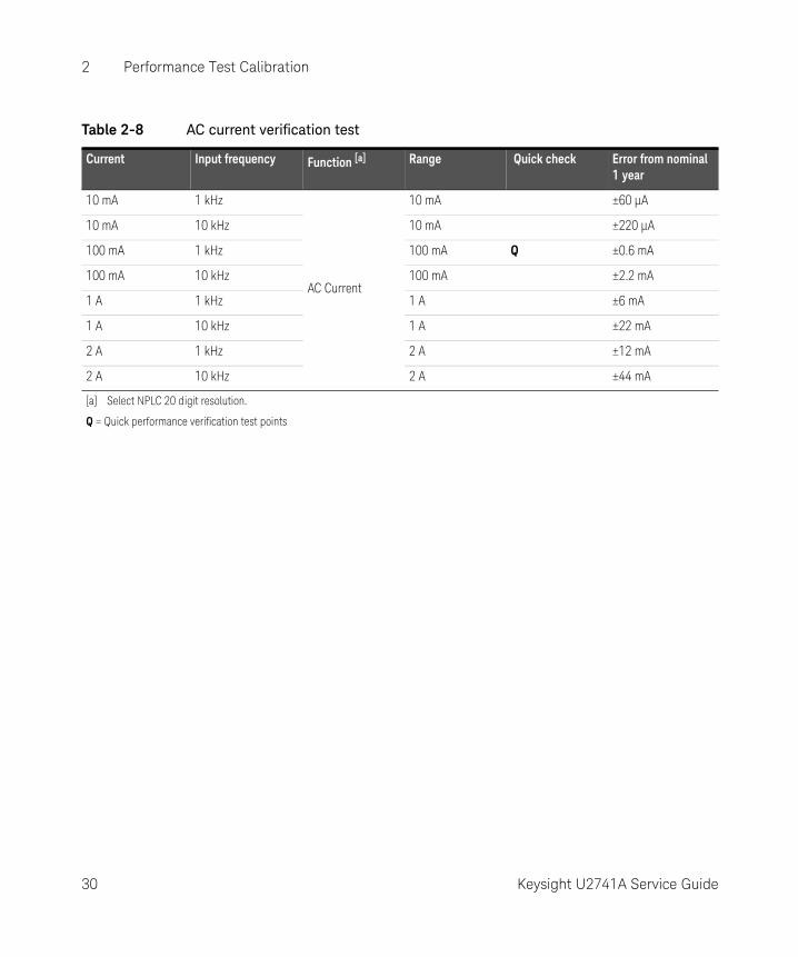
AC current verification test
AC current configuration: (CONFigure:CURRent:AC [<range|MIN|MAX|AUTO> [,resolution|MIN|MAX|DEF>]])
1 Select the AC Current function.
2 Select each range in the order based on the input current and frequency. Compare the measurement results with the appropriate test limits shown in Table 2-8. (Be certain to allow for appropriate source settling.)
250 V 30 kHz 250 V ±2.75 V
250 V 100 kHz 250 V ±8 V
[a] Select NPLC 20 digit resolution.
Q = Quick performance verification test points
Table 2-7 AC volts verification test error (continued)
Voltage Input frequency Function [a] Range Quick check Error from nominal 1 year
CAUTIONSet the calibrator output to 0 V before disconnecting it from the multimeter input terminals.
Keysight U2741A Service Guide 29
2 Performance Test Calibration
Table 2-8 AC current verification test
Current Input frequency Function [a] Range Quick check Error from nominal 1 year
10 mA 1 kHz
AC Current
10 mA ±60 µA
10 mA 10 kHz 10 mA ±220 µA
100 mA 1 kHz 100 mA Q ±0.6 mA
100 mA 10 kHz 100 mA ±2.2 mA
1 A 1 kHz 1 A ±6 mA
1 A 10 kHz 1 A ±22 mA
2 A 1 kHz 2 A ±12 mA
2 A 10 kHz 2 A ±44 mA
[a] Select NPLC 20 digit resolution.
Q = Quick performance verification test points
30 Keysight U2741A Service Guide
Performance Test Calibration 2
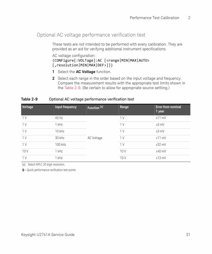
Optional AC voltage performance verification test
These tests are not intended to be performed with every calibration. They are provided as an aid for verifying additional instrument specifications.
AC voltage configuration: (CONFigure[:VOLTage]:AC [<range|MIN|MAX|AUTO> [,resolution|MIN|MAX|DEF>]])
1 Select the AC Voltage function.
2 Select each range in the order based on the input voltage and frequency. Compare the measurement results with the appropriate test limits shown in the Table 2-9. (Be certain to allow for appropriate source settling.)
Table 2-9 Optional AC voltage performance verification test
Voltage Input frequency Function [a] Range Error from nominal 1 year
1 V 45 Hz
AC Voltage
1 V ±11 mV
1 V 1 kHz 1 V ±3 mV
1 V 10 kHz 1 V ±3 mV
1 V 30 kHz 1 V ±11 mV
1 V 100 kHz 1 V ±32 mV
10 V 1 kHz 10 V ±40 mV
1 V 1 kHz 10 V ±13 mV
[a] Select NPLC 20 digit resolution.
Q = Quick performance verification test points
Keysight U2741A Service Guide 31
2 Performance Test Calibration
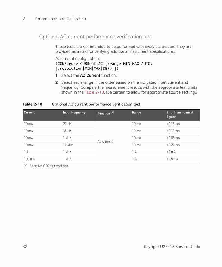
Optional AC current performance verification test
These tests are not intended to be performed with every calibration. They are provided as an aid for verifying additional instrument specifications.
AC current configuration: (CONFigure:CURRent:AC [<range|MIN|MAX|AUTO> [,resolution|MIN|MAX|DEF>]])
1 Select the AC Current function.
2 Select each range in the order based on the indicated input current and frequency. Compare the measurement results with the appropriate test limits shown in the Table 2-10. (Be certain to allow for appropriate source settling.)
Table 2-10 Optional AC current performance verification test
Current Input frequency Function [a] Range Error from nominal 1 year
10 mA 20 Hz
AC Current
10 mA ±0.16 mA
10 mA 45 Hz 10 mA ±0.16 mA
10 mA 1 kHz 10 mA ±0.06 mA
10 mA 10 kHz 10 mA ±0.22 mA
1 A 1 kHz 1 A ±6 mA
100 mA 1 kHz 1 A ±1.5 mA
[a] Select NPLC 20 digit resolution.
32 Keysight U2741A Service Guide
Keysight U2741A USB Modular 5.5 Digits Digital MultimeterService Guide
3 Service
Types of Service Available 34Repackaging for Shipment 35Cleaning 36Electrostatic Discharge (ESD) Precautions 37To Replace a Current Input Fuse 38Troubleshooting the modular DMM 39
33
3 Service
Types of Service Available
If your instrument fails during the warranty period, Keysight Technologies will repair or replace it under the terms of your warranty. After your warranty expires, Keysight offers repair services at competitive prices.
Extended service contracts
Many Keysight products are available with optional service contracts that extend the covered period after the standard warranty expires. If you have such a service contract and your instrument fails during the covered period, Keysight Technologies will repair or replace it in accordance with the contract.
Obtaining repair service (Worldwide)
To obtain service for your instrument (in-warranty, under service contract, or post-warranty), contact your nearest Keysight Technologies Service Center. They will arrange to have your unit repaired or replaced, and can provide warranty or repair-cost information where applicable.
To obtain warranty, service, or technical support information you can contact Keysight Technologies at one of the following telephone numbers:
United States: (800) 829-4444
Canada: (877) 894 4414
China: (800) 810 0189
Europe: 31 20 547 2111
Japan: (81) 426 56 7832
Korea: (080) 769 0800
Latin America: (305) 269 7500
Taiwan: 0800 047 866
Other Asia Pacific Countries: (65) 6375 8100
Or visit Keysight worlwide Web at: www.keysight.com/find/assist
Or contact your Keysight Technologies Representative. Before shipping your instrument, ask the Keysight Technologies Service Center to provide shipping instructions, including what components to ship. Keysight recommends that you retain the original shipping carton for use in such shipments.
34 Keysight U2741A Service Guide
Service 3
Repackaging for Shipment
If the unit is to be shipped to Keysight for service or repair, be sure to:
– Attach a tag to the unit identifying the owner and indicating the required service or repair. Include the model number and full serial number.
– Place the unit in its original container with appropriate packaging material for shipping.
– Secure the container with strong tape or metal bands.
– If the original shipping container is not available, place your unit in a container which will ensure at least 4 inches of compressible packaging material around all sides for the instrument. Use static-free packaging materials to avoid additional damage to your unit.
Keysight suggests that you always insure shipments.
Keysight U2741A Service Guide 35
3 Service
Cleaning
Clean the outside of the instrument with a soft, lint-free, slightly dampened cloth. Do not use detergent. Disassembly is not required or recommended for cleaning.
36 Keysight U2741A Service Guide
Service 3
Electrostatic Discharge (ESD) Precautions
Almost all electrical components can be damaged by electrostatic discharge (ESD) during handling. Component damage can occur at electrostatic discharge voltages as low as 50 volts.
The following guidelines will help prevent ESD damage when servicing the modular DMM or any electronic device.
– Disassemble instruments only in a static-free work area.
– Use a conductive work area to dissipate static charge.
– Use a conductive wrist strap to dissipate static charge accumulation.
– Minimize handling.
– Keep replacement parts in original static-free packaging.
– Remove all plastic, styrofoam, vinyl, paper, and other static-generating materials from the immediate work area.
– Use only antistatic solder remover.
Keysight U2741A Service Guide 37
3 Service
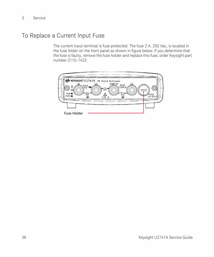
To Replace a Current Input Fuse
The current input terminal is fuse protected. The fuse 2 A, 250 Vac, is located in the fuse folder on the front panel as shown in figure below. If you determine that the fuse is faulty, remove the fuse holder and replace this fuse, order Keysight part number 2110-1422.
Fuse Holder
38 Keysight U2741A Service Guide
Service 3
Troubleshooting the modular DMM
This section provides a brief check list of common failures. Before troubleshooting or repairing the modular DMM, make sure the failure is in the instrument rather than any external connections.
Unit is inoperative
– Verify that the AC/DC adapter is connected to the modular DMM.
– Verify that the front panel power indicator is lit.
– Verify that the USB cable is connected to the PC and the USB inlet in modular DMM.
Current input is inoperative
Verify that the front panel 2 A, 250 V current fuse is functional.
Power supply problems
Check that the AC/DC adapter is function and make sure that its output voltage is 12 V.
Contact Keysight Technologies Service Center to obtain technical assistance, if necessary.
Keysight U2741A Service Guide 39

3 Service
THIS PAGE HAS BEEN INTENTIONALLY LEFT BLANK.
40 Keysight U2741A Service Guide
Keysight U2741A USB Modular 5.5 Digits Digital MultimeterService Guide
4 Replacement Parts
To Order Replaceable Parts 42General Disassemble 43
This section provides the information of the orderable replacement parts for U2741A USB modular digital multimeter. The parts available for replacement are listed in Table 4-1 with the reference part numbers and the respective part names.
41
4 Replacement Parts
To Order Replaceable Parts
You can order the replacement parts from Keysight using the part number provided in the table below. To order replacement parts from Keysight, do the following:
1 Identify the Keysight part number of the required parts as shown in the replacement parts list.
2 Contact your nearest Keysight Sales Office or Service Center.
3 Provide the instrument's model number and serial number.
Table 4-1 List of replacement parts
Part number Description
U2702-68301 L-Bracket Assembly
U2702-40004 Rubber Bumper
U2702-60202 Rear Panel Assembly
2110-1422 2 A 250 Vac Fuse
2110-0970 Front Panel Fuse Holder
42 Keysight U2741A Service Guide
Replacement Parts 4
General Disassemble
This chapter provides the step-by-step guide on how to dismantle the module and install the replacement assembly. To reassemble the module, follow the instructions in reverse order.
The removable assemblies include:
– Metal casing
– Rear metal casing
– Front metal casing, which is attached to the carrier board and measurement board
– Front and rear rubber bumper
Mechanical Disassemble
Follow the instructions in this section for the instrument disassembly process.
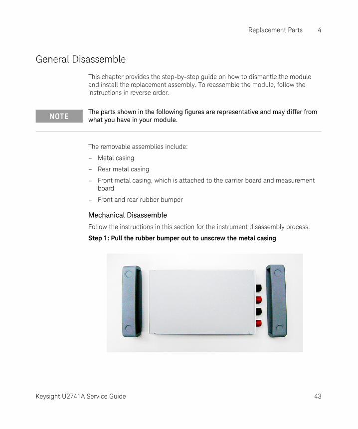
Step 1: Pull the rubber bumper out to unscrew the metal casing
NOTEThe parts shown in the following figures are representative and may differ from what you have in your module.
Keysight U2741A Service Guide 43
4 Replacement Parts
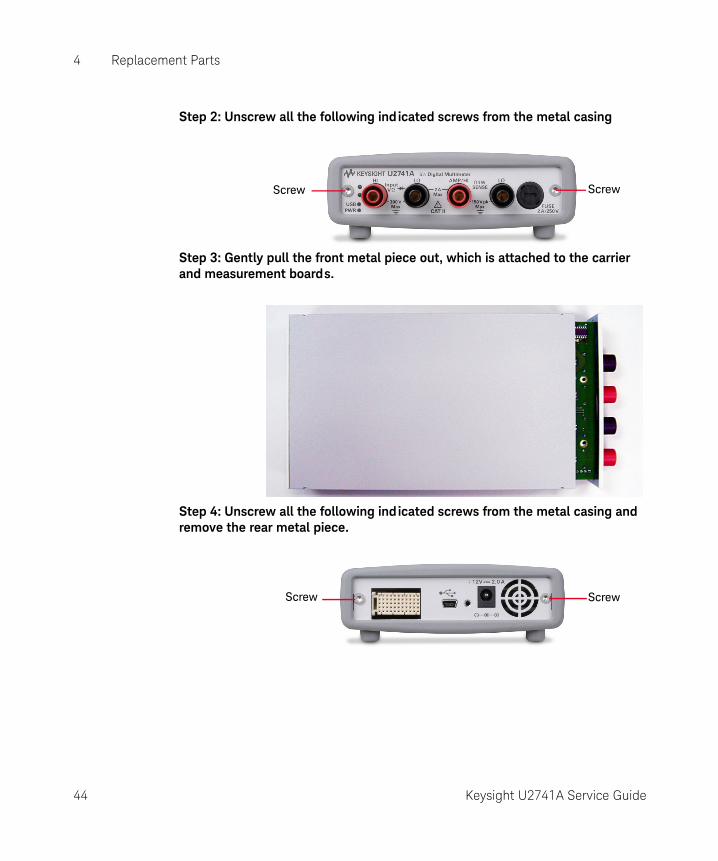
Step 2: Unscrew all the following ind icated screws from the metal casing
Step 3: Gently pull the front metal piece out, which is attached to the carrier and measurement boards.
Step 4: Unscrew all the following ind icated screws from the metal casing and remove the rear metal piece.
ScrewScrew
ScrewScrew
44 Keysight U2741A Service Guide

This information is subject to change without notice. Always refer to the Keysight website for the latest revision.
© Keysight Technologies 2008 - 2017 Edition 5, March 17, 2017
Printed in Malaysia
*U2741-90012*U2741-90012 www.keysight.com