Embed Size (px)
Citation preview
ISO / DIS 14230 Road Vehicles - Diagnostic Systems Keyword Protocol 2000 Part 2: Data Link Layer Status: Draft International Standard
Date: December 16, 1996

ISO / DIS 14230 - 2 : KEYWORD PROTOCOL 2000 - PART 2: DATA LINK LAYER
Page: 2 of 28
THIS PAGE INTENTIONALLY LEFT BLANK
ISO / DIS 14230 - 2 : KEYWORD PROTOCOL 2000 - PART 2: DATA LINK LAYER
Page: 3 of 28
Table of contents
1 - SCOPE...........................................................................................................................6
2 - NORMATIVE REFERENCE ...........................................................................................7
3 - PHYSICAL TOPOLOGY ................................................................................................8
4 - MESSAGE STRUCTURE...............................................................................................8
4.1 - Header................................................................................................................................................................... 9 4.1.1 - Format byte..................................................................................................................................................... 9 4.1.2 - Target address byte......................................................................................................................................... 9 4.1.3 - Source address byte ........................................................................................................................................ 9 4.1.4 - Length byte................................................................................................................................................... 10 4.1.5 - Use of header bytes ...................................................................................................................................... 10
4.2 - Data Bytes........................................................................................................................................................... 11
4.3 - Checksum Byte................................................................................................................................................... 11
4.4 - Timing ................................................................................................................................................................. 11 4.4.1 - Timing Exceptions........................................................................................................................................ 13
5 - COMMUNICATION SERVICES ...................................................................................14
5.1 - StartCommunication Service............................................................................................................................ 15 5.1.1 - Service Definition......................................................................................................................................... 15 5.1.2 - Service Purpose ............................................................................................................................................ 15 5.1.3 - Service Table ................................................................................................................................................ 15 5.1.4 - Service Procedure......................................................................................................................................... 15 5.1.5 - Implementation............................................................................................................................................. 15
5.1.5.1 - Key bytes............................................................................................................................................... 17 5.1.5.2 - Initialisation with 5 Baud address word................................................................................................ 18
5.1.5.2.1 - CARB initialisation........................................................................................................................ 18 5.1.5.2.2 - 5 Baud Initialisation....................................................................................................................... 18 5.1.5.2.3 - Functional initialisation ................................................................................................................. 19 5.1.5.2.4 - Physical initialisation ..................................................................................................................... 19
5.1.5.3 - Fast Initialisation................................................................................................................................... 19
5.2 - StopCommunication Service ............................................................................................................................ 20 5.2.1 - Service Definition......................................................................................................................................... 20
5.2.1.1 - Service Purpose..................................................................................................................................... 20 5.2.1.2 - Service Table......................................................................................................................................... 20 5.2.1.3 - Service Procedure ................................................................................................................................. 21
5.2.2 - Implementation............................................................................................................................................. 21
5.3 - AccessTimingParameter Service ...................................................................................................................... 22 5.3.1 - Service Definition......................................................................................................................................... 22
5.3.1.1 - Service Purpose..................................................................................................................................... 22 5.3.1.2 - Service Table......................................................................................................................................... 22 5.3.1.3 - Service Procedure ................................................................................................................................. 22
5.3.2 - Implementation............................................................................................................................................. 23
ISO / DIS 14230 - 2 : KEYWORD PROTOCOL 2000 - PART 2: DATA LINK LAYER
Page: 4 of 28
5.4 - SendData Service ............................................................................................................................................... 25 5.4.1 - Service Definition......................................................................................................................................... 25
5.4.1.1 - Service Purpose..................................................................................................................................... 25 5.4.1.2 - Service Table......................................................................................................................................... 25 5.4.1.3 - Service Procedure ................................................................................................................................. 25
6 - ERROR HANDLING.....................................................................................................26
6.1 - Start Communication service............................................................................................................................ 26
6.2 - Mainstream Communications........................................................................................................................... 26
6.3 - ECU detected Tester transmission error ......................................................................................................... 26
6.4 - Tester detected error in vehicle response......................................................................................................... 26
6.5 - ECU detected error in ECU response .............................................................................................................. 26
6.6 - Tester detected error in tester transmission.................................................................................................... 26
ISO / DIS 14230 - 2 : KEYWORD PROTOCOL 2000 - PART 2: DATA LINK LAYER
Page: 5 of 28
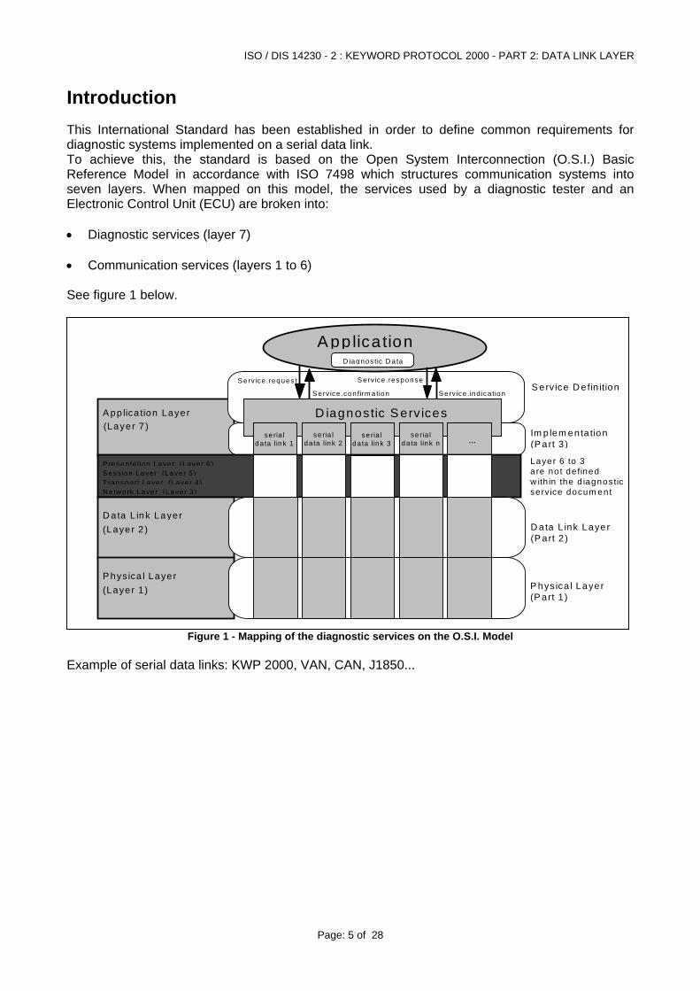
Introduction This International Standard has been established in order to define common requirements for diagnostic systems implemented on a serial data link. To achieve this, the standard is based on the Open System Interconnection (O.S.I.) Basic Reference Model in accordance with ISO 7498 which structures communication systems into seven layers. When mapped on this model, the services used by a diagnostic tester and an Electronic Control Unit (ECU) are broken into: • Diagnostic services (layer 7) • Communication services (layers 1 to 6) See figure 1 below.
A pp lica tion Layer
A pp lica tion
S erv ice .request
S erv ice .con firm a tion
S erv ice .response
S erv ice .ind ica tion
(Layer 7 )Im p lem enta tion(P art 3 )
S erv ice D e fin ition
D ata L ink Layer(P art 2 )
P hys ica l Layer(P art 1 )
D iagnostic S erv ices
D iagnostic D a ta
...se ria l
da ta link 1se ria l
da ta link 2se ria l
da ta link 3se ria l
da ta link n
D a ta L ink Layer(Laye r 2 )
P hysica l Layer
S ess ion Layer (Layer 5)P resenta tion Laye r (Laye r 6 )
N e tw ork Laye r (Laye r 3)T ransport Layer (Layer 4 )
Layer 6 to 3are no t de finedw ith in the d iagnosticserv ice docum ent
(Laye r 1 )
Figure 1 - Mapping of the diagnostic services on the O.S.I. Model
Example of serial data links: KWP 2000, VAN, CAN, J1850...
ISO / DIS 14230 - 2 : KEYWORD PROTOCOL 2000 - PART 2: DATA LINK LAYER
Page: 6 of 28
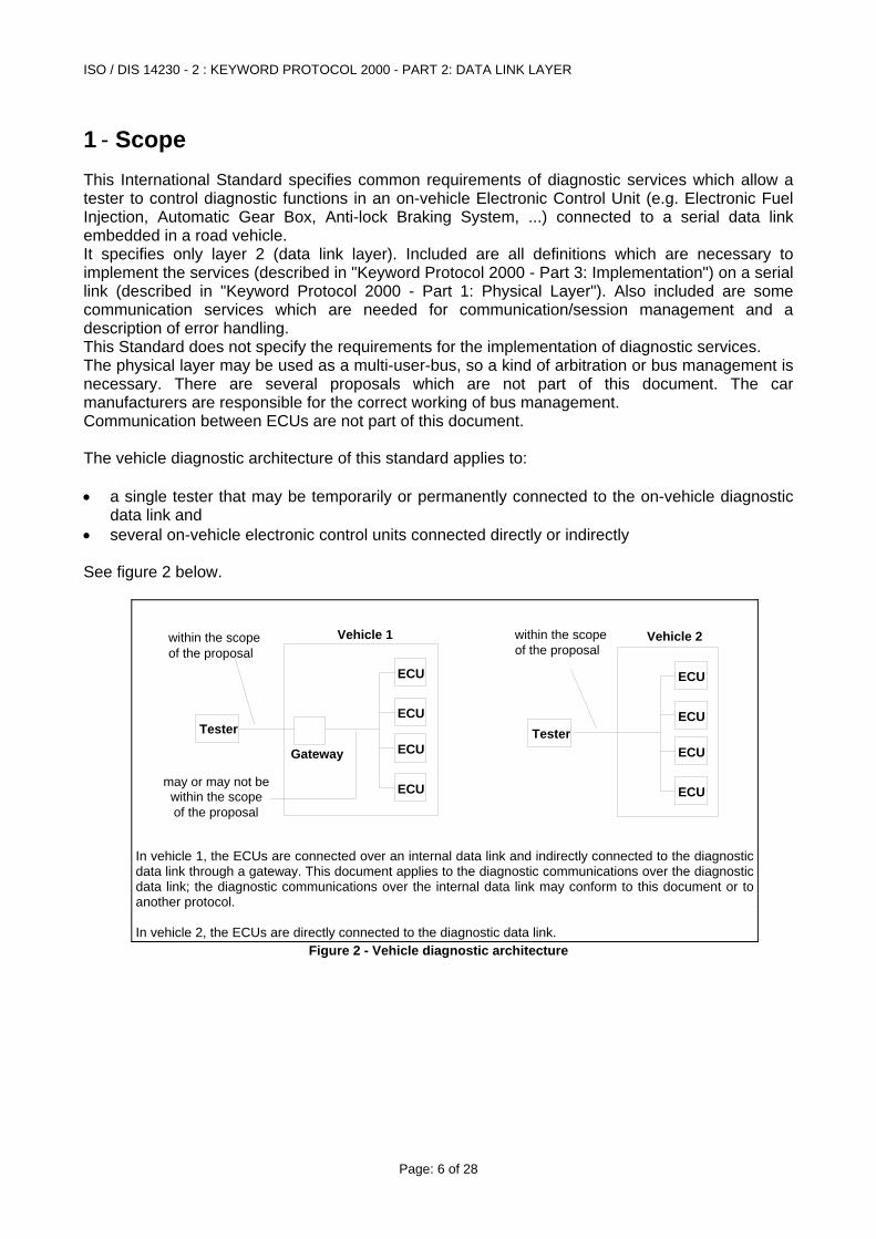
1 - Scope This International Standard specifies common requirements of diagnostic services which allow a tester to control diagnostic functions in an on-vehicle Electronic Control Unit (e.g. Electronic Fuel Injection, Automatic Gear Box, Anti-lock Braking System, ...) connected to a serial data link embedded in a road vehicle. It specifies only layer 2 (data link layer). Included are all definitions which are necessary to implement the services (described in "Keyword Protocol 2000 - Part 3: Implementation") on a serial link (described in "Keyword Protocol 2000 - Part 1: Physical Layer"). Also included are some communication services which are needed for communication/session management and a description of error handling. This Standard does not specify the requirements for the implementation of diagnostic services. The physical layer may be used as a multi-user-bus, so a kind of arbitration or bus management is necessary. There are several proposals which are not part of this document. The car manufacturers are responsible for the correct working of bus management. Communication between ECUs are not part of this document. The vehicle diagnostic architecture of this standard applies to: • a single tester that may be temporarily or permanently connected to the on-vehicle diagnostic
data link and • several on-vehicle electronic control units connected directly or indirectly See figure 2 below.
Tester
Gateway
within the scopeof the proposal
ECU
ECU
ECU
ECU
may or may not bewithin the scope of the proposal
Vehicle 1
Tester
within the scopeof the proposal
ECU
ECU
ECU
ECU
Vehicle 2
In vehicle 1, the ECUs are connected over an internal data link and indirectly connected to the diagnostic data link through a gateway. This document applies to the diagnostic communications over the diagnostic data link; the diagnostic communications over the internal data link may conform to this document or to another protocol. In vehicle 2, the ECUs are directly connected to the diagnostic data link.
Figure 2 - Vehicle diagnostic architecture
ISO / DIS 14230 - 2 : KEYWORD PROTOCOL 2000 - PART 2: DATA LINK LAYER
Page: 7 of 28
2 - Normative Reference The following standards contain provisions which, through reference in this text, constitute provisions of this document. All standards are subject to revision, and parties to agreement based on this document are encouraged to investigate the possibility of applying the most recent editions of the standards listed below. Members of ISO maintain registers of currently valid International Standards. ISO 7498-1:1984 Information processing systems - Open systems interconnection -
Basic reference model. ISO TR 8509:1987 Information processing systems - Open systems interconnection -
Conventions of services. ISO 4092:1988/Cor.1:1991 Road vehicles - Testers for motor vehicles - Vocabulary Technical
Corrigendum 1. SAE J2012 Diagnostic Trouble Codes ISO 9141:1989 Road vehicles - Diagnostic systems - Requirements for
interchange of digital information ISO 9141-2:1994 Road vehicles - Diagnostic systems- Part 2: CARB requirements
for interchange of digital information SAE J1979: Dec,1991 E/E Diagnostic Test Modes SAE J2012: 1994 Recommended Format and Messages for Diagnostic Trouble
Codes SAE J2178 :June, 1993 Class B Data Communication Network Messages ISO 14229:1996 Road Vehicles - Diagnostic systems - Diagnostic Services
Specification ISO 14230-1:1996 Road Vehicles - Diagnostic systems - Keyword Protocol 2000 -
Part 1: Physical Layer ISO 14230-3:1996 Road Vehicles - Diagnostic systems - Keyword Protocol 2000 -
Part 3: Implementation ISO 14230-4:1996 Road Vehicles - Diagnostic systems - Keyword Protocol 2000 -
Part 4: Requirements For Emission Related Systems
ISO / DIS 14230 - 2 : KEYWORD PROTOCOL 2000 - PART 2: DATA LINK LAYER
Page: 8 of 28
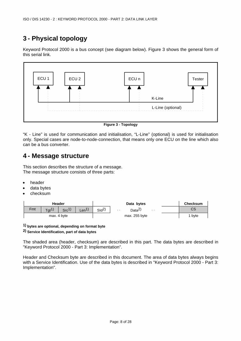
3 - Physical topology Keyword Protocol 2000 is a bus concept (see diagram below). Figure 3 shows the general form of this serial link.
ECU 2 ECU n TesterECU 1
K-Line
L-Line (optional)
Figure 3 - Topology “K - Line” is used for communication and initialisation, “L-Line” (optional) is used for initialisation only. Special cases are node-to-node-connection, that means only one ECU on the line which also can be a bus converter.
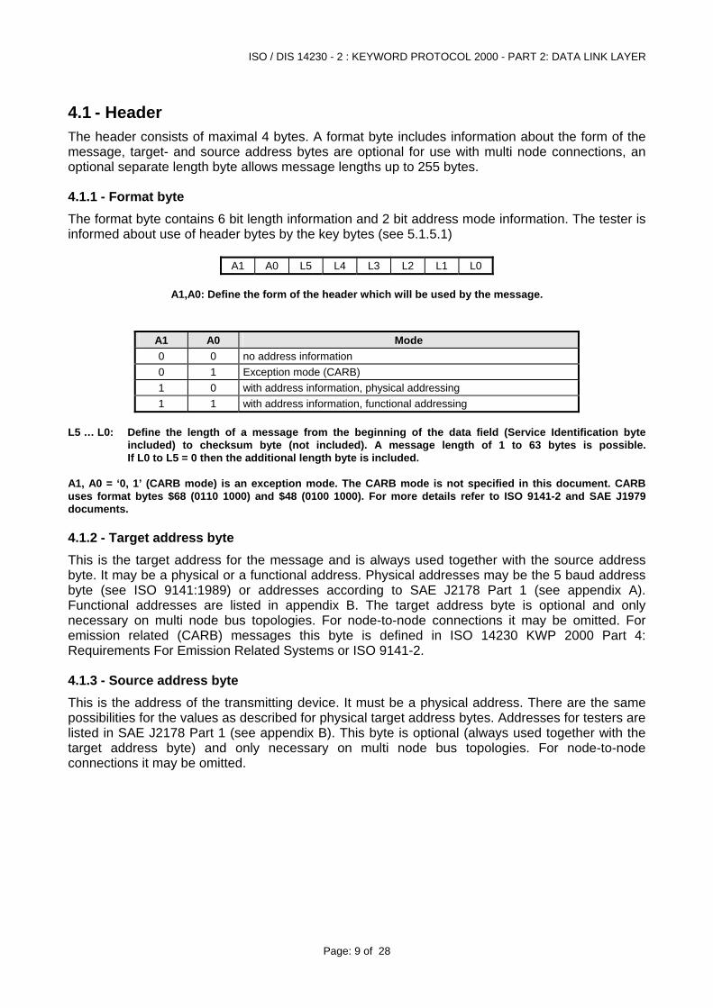
4 - Message structure This section describes the structure of a message. The message structure consists of three parts: • header • data bytes • checksum
Header Data bytes Checksum Fmt CS Tgt1) Src1) Len1) SId2) . . Data2) . .
max. 4 byte max. 255 byte 1 byte 1) bytes are optional, depending on format byte 2) Service Identification, part of data bytes The shaded area (header, checksum) are described in this part. The data bytes are described in "Keyword Protocol 2000 - Part 3: Implementation”. Header and Checksum byte are described in this document. The area of data bytes always begins with a Service Identification. Use of the data bytes is described in "Keyword Protocol 2000 - Part 3: Implementation".
ISO / DIS 14230 - 2 : KEYWORD PROTOCOL 2000 - PART 2: DATA LINK LAYER
Page: 9 of 28
4.1 - Header The header consists of maximal 4 bytes. A format byte includes information about the form of the message, target- and source address bytes are optional for use with multi node connections, an optional separate length byte allows message lengths up to 255 bytes.
4.1.1 - Format byte The format byte contains 6 bit length information and 2 bit address mode information. The tester is informed about use of header bytes by the key bytes (see 5.1.5.1)
A1 A0 L5 L4 L3 L2 L1 L0
A1,A0: Define the form of the header which will be used by the message.
A1 A0 Mode 0 0 no address information 0 1 Exception mode (CARB) 1 0 with address information, physical addressing 1 1 with address information, functional addressing
L5 … L0: Define the length of a message from the beginning of the data field (Service Identification byte
included) to checksum byte (not included). A message length of 1 to 63 bytes is possible. If L0 to L5 = 0 then the additional length byte is included.
A1, A0 = ‘0, 1’ (CARB mode) is an exception mode. The CARB mode is not specified in this document. CARB uses format bytes $68 (0110 1000) and $48 (0100 1000). For more details refer to ISO 9141-2 and SAE J1979 documents.
4.1.2 - Target address byte This is the target address for the message and is always used together with the source address byte. It may be a physical or a functional address. Physical addresses may be the 5 baud address byte (see ISO 9141:1989) or addresses according to SAE J2178 Part 1 (see appendix A). Functional addresses are listed in appendix B. The target address byte is optional and only necessary on multi node bus topologies. For node-to-node connections it may be omitted. For emission related (CARB) messages this byte is defined in ISO 14230 KWP 2000 Part 4: Requirements For Emission Related Systems or ISO 9141-2.
4.1.3 - Source address byte This is the address of the transmitting device. It must be a physical address. There are the same possibilities for the values as described for physical target address bytes. Addresses for testers are listed in SAE J2178 Part 1 (see appendix B). This byte is optional (always used together with the target address byte) and only necessary on multi node bus topologies. For node-to-node connections it may be omitted.
ISO / DIS 14230 - 2 : KEYWORD PROTOCOL 2000 - PART 2: DATA LINK LAYER
Page: 10 of 28
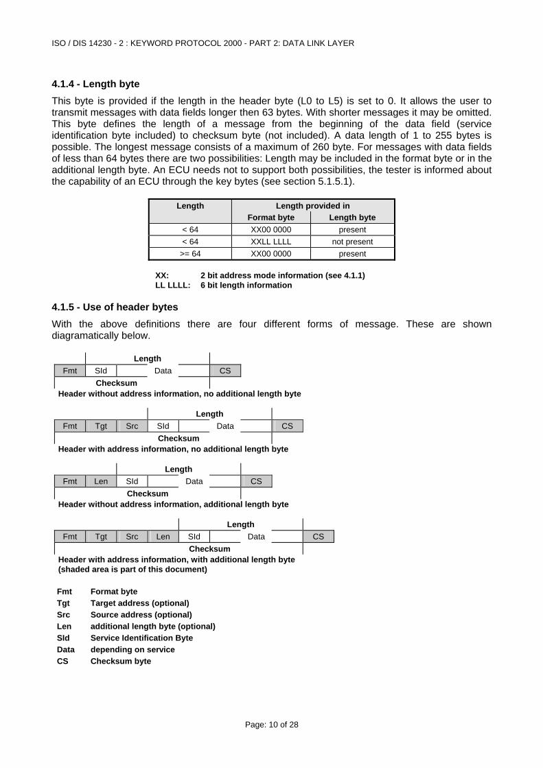
4.1.4 - Length byte This byte is provided if the length in the header byte (L0 to L5) is set to 0. It allows the user to transmit messages with data fields longer then 63 bytes. With shorter messages it may be omitted. This byte defines the length of a message from the beginning of the data field (service identification byte included) to checksum byte (not included). A data length of 1 to 255 bytes is possible. The longest message consists of a maximum of 260 byte. For messages with data fields of less than 64 bytes there are two possibilities: Length may be included in the format byte or in the additional length byte. An ECU needs not to support both possibilities, the tester is informed about the capability of an ECU through the key bytes (see section 5.1.5.1).
Length Length provided in Format byte Length byte
< 64 XX00 0000 present < 64 XXLL LLLL not present
>= 64 XX00 0000 present XX: 2 bit address mode information (see 4.1.1) LL LLLL: 6 bit length information
4.1.5 - Use of header bytes With the above definitions there are four different forms of message. These are shown diagramatically below.
Length Fmt SId Data CS
Checksum Header without address information, no additional length byte
Length
Fmt Tgt Src SId Data CS Checksum
Header with address information, no additional length byte
Length Fmt Len SId Data CS
Checksum Header without address information, additional length byte
Length
Fmt Tgt Src Len SId Data CS Checksum
Header with address information, with additional length byte (shaded area is part of this document)
Fmt Format byte Tgt Target address (optional) Src Source address (optional) Len additional length byte (optional) SId Service Identification Byte Data depending on service CS Checksum byte
ISO / DIS 14230 - 2 : KEYWORD PROTOCOL 2000 - PART 2: DATA LINK LAYER
Page: 11 of 28
4.2 - Data Bytes The data field may contain up to 63 or up to 255 bytes of information, depending on the use of length information. The first byte of the data field is the Service Identification Byte. It may be followed by parameters and data depending on the selected service. These bytes are defined in "Keyword Protocol 2000 - Part 3: - Implementation" (for diagnostic services) and in section 5 of this document (for communication services).
4.3 - Checksum Byte The checksum byte (CS) inserted at the end of the message block is defined as the simple 8-bit sum series of all bytes in the message, excluding the checksum.
If the message is <1> <2> <3> ... <N> , <CS>
where <i> (1 <= i <= N ) is the numeric value of the ith byte of the message,
then <CS> = <CS>N
where <CS>i ( i = 2 to N )
is defined as <CS>i = { <CS> i-1 + <i> } Modulo 256 and <CS>1 = <1> Additional security may be included in the data field as defined by the manufacturer.
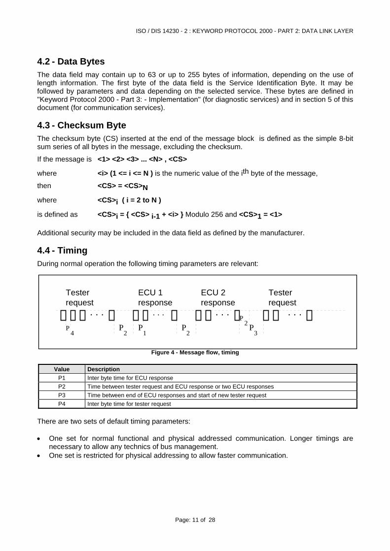
4.4 - Timing During normal operation the following timing parameters are relevant:
Tester ECU 1
P4
. . .P
2P
1
. . .
P2
. . .
ECU 2
. . .P
3
Testerrequest response response request
P2
Figure 4 - Message flow, timing
Value Description
P1 Inter byte time for ECU response P2 Time between tester request and ECU response or two ECU responses P3 Time between end of ECU responses and start of new tester request P4 Inter byte time for tester request
There are two sets of default timing parameters: • One set for normal functional and physical addressed communication. Longer timings are
necessary to allow any technics of bus management. • One set is restricted for physical addressing to allow faster communication.
ISO / DIS 14230 - 2 : KEYWORD PROTOCOL 2000 - PART 2: DATA LINK LAYER
Page: 12 of 28
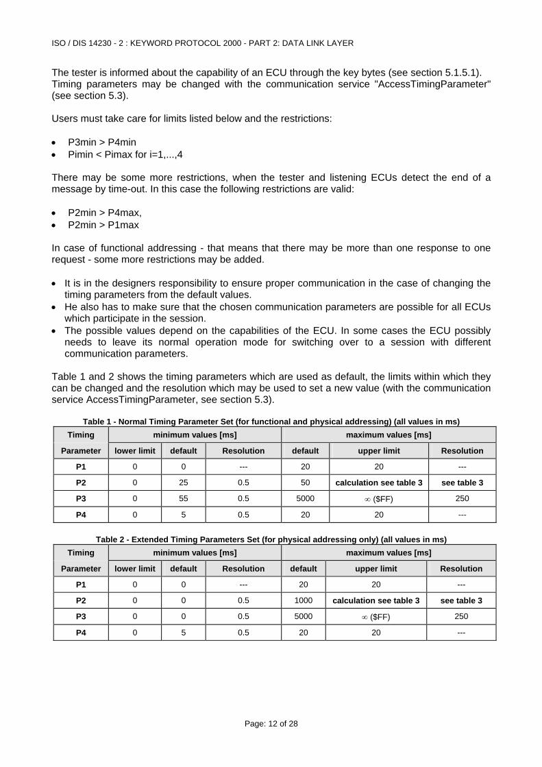
The tester is informed about the capability of an ECU through the key bytes (see section 5.1.5.1). Timing parameters may be changed with the communication service "AccessTimingParameter" (see section 5.3). Users must take care for limits listed below and the restrictions: • P3min > P4min • Pimin < Pimax for i=1,...,4 There may be some more restrictions, when the tester and listening ECUs detect the end of a message by time-out. In this case the following restrictions are valid: • P2min > P4max, • P2min > P1max In case of functional addressing - that means that there may be more than one response to one request - some more restrictions may be added. • It is in the designers responsibility to ensure proper communication in the case of changing the
timing parameters from the default values. • He also has to make sure that the chosen communication parameters are possible for all ECUs
which participate in the session. • The possible values depend on the capabilities of the ECU. In some cases the ECU possibly
needs to leave its normal operation mode for switching over to a session with different communication parameters.
Table 1 and 2 shows the timing parameters which are used as default, the limits within which they can be changed and the resolution which may be used to set a new value (with the communication service AccessTimingParameter, see section 5.3).
Table 1 - Normal Timing Parameter Set (for functional and physical addressing) (all values in ms) Timing minimum values [ms] maximum values [ms]
Parameter lower limit default Resolution default upper limit Resolution
P1 0 0 --- 20 20 ---
P2 0 25 0.5 50 calculation see table 3 see table 3
P3 0 55 0.5 5000 ∞ ($FF) 250
P4 0 5 0.5 20 20 ---
Table 2 - Extended Timing Parameters Set (for physical addressing only) (all values in ms)
Timing minimum values [ms] maximum values [ms]
Parameter lower limit default Resolution default upper limit Resolution
P1 0 0 --- 20 20 ---
P2 0 0 0.5 1000 calculation see table 3 see table 3
P3 0 0 0.5 5000 ∞ ($FF) 250
P4 0 5 0.5 20 20 ---
ISO / DIS 14230 - 2 : KEYWORD PROTOCOL 2000 - PART 2: DATA LINK LAYER
Page: 13 of 28
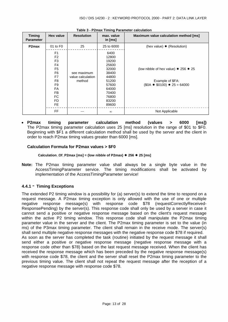
Table 3 - P2max Timing Parameter calculation Timing
Parameter Hex value Resolution max. value
in [ms] Maximum value calculation method [ms]
P2max 01 to F0 25 25 to 6000 (hex value) (Resolution)
F1 F2 F3 F4 F5 F6 F7 F8 F9 FA FB FC FD FE
see maximum value calculation
method
6400 12800 19200 25600 32000 38400 44800 51200 57600 64000 70400 76800 83200 89600
(low nibble of hex value) 256 25
Example of $FA: ($0A $0100) 25 = 64000
FF --- ∞ Not Applicable
• P2max timing parameter calculation method (values > 6000 [ms])
The P2max timing parameter calculation uses 25 [ms] resolution in the range of $01 to $F0. Beginning with $F1 a different calculation method shall be used by the server and the client in order to reach P2max timing values greater than 6000 [ms]. Calculation Formula for P2max values > $F0
Calculation_Of_P2max [ms] = (low nibble of P2max) 256 25 [ms]
Note: The P2max timing parameter value shall always be a single byte value in the
AccessTimingParameter service. The timing modifications shall be activated by implementation of the AccessTimingParameter service!
4.4.1 - Timing Exceptions
The extended P2 timing window is a possibility for (a) server(s) to extend the time to respond on a request message. A P2max timing exception is only allowed with the use of one or multiple negative response message(s) with response code $78 (requestCorrectlyReceived-ResponsePending) by the server(s). This response code shall only be used by a server in case it cannot send a positive or negative response message based on the client's request message within the active P2 timing window. This response code shall manipulate the P2max timing parameter value in the server and the client. The P2max timing parameter is set to the value (in ms) of the P3max timing parameter. The client shall remain in the receive mode. The server(s) shall send multiple negative response messages with the negative response code $78 if required. As soon as the server has completed the task (routine) initiated by the request message it shall send either a positive or negative response message (negative response message with a response code other than $78) based on the last request message received. When the client has received the response message which has been preceded by the negative response message(s) with response code $78, the client and the server shall reset the P2max timing parameter to the previous timing value. The client shall not repeat the request message after the reception of a negative response message with response code $78.
ISO / DIS 14230 - 2 : KEYWORD PROTOCOL 2000 - PART 2: DATA LINK LAYER
Page: 14 of 28
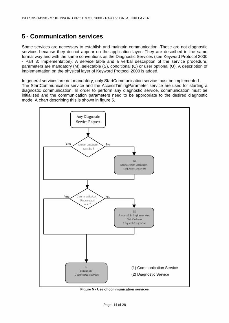
5 - Communication services Some services are necessary to establish and maintain communication. Those are not diagnostic services because they do not appear on the application layer. They are described in the same formal way and with the same conventions as the Diagnostic Services (see Keyword Protocol 2000 - Part 3: Implementation): A service table and a verbal description of the service procedure; parameters are mandatory (M), selectable (S), conditional (C) or user optional (U). A description of implementation on the physical layer of Keyword Protocol 2000 is added. In general services are not mandatory, only StartCommunication service must be implemented. The StartCommunication service and the AccessTimingParameter service are used for starting a diagnostic communication. In order to perform any diagnostic service, communication must be initialised and the communication parameters need to be appropriate to the desired diagnostic mode. A chart describing this is shown in figure 5.
(2) SendData
Diagnostic Service
(1) AccessTim ingParam eter
(Set Values) Request/Response
(1) Start Com m unication Request/Response
Com m unication Param eters
o.k.?
Com m unication running?
Any Diagnostic Service Request
NoYes
NoYes
(1) Communication Service
(2) Diagnostic Service
Figure 5 - Use of communication services
ISO / DIS 14230 - 2 : KEYWORD PROTOCOL 2000 - PART 2: DATA LINK LAYER
Page: 15 of 28
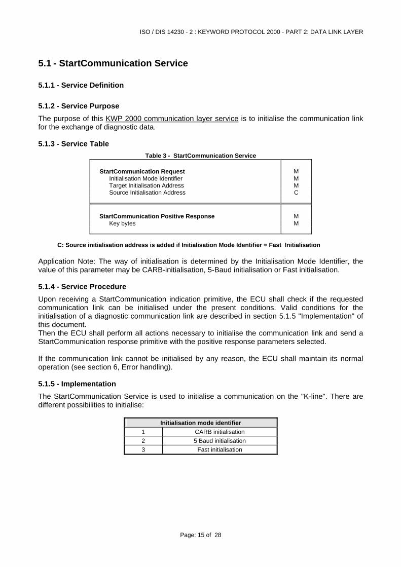
5.1 - StartCommunication Service
5.1.1 - Service Definition
5.1.2 - Service Purpose The purpose of this KWP 2000 communication layer service is to initialise the communication link for the exchange of diagnostic data.
5.1.3 - Service Table Table 3 - StartCommunication Service
StartCommunication Request M Initialisation Mode Identifier M Target Initialisation Address M Source Initialisation Address C
StartCommunication Positive Response M Key bytes M
C: Source initialisation address is added if Initialisation Mode Identifier = Fast Initialisation
Application Note: The way of initialisation is determined by the Initialisation Mode Identifier, the value of this parameter may be CARB-initialisation, 5-Baud initialisation or Fast initialisation.
5.1.4 - Service Procedure Upon receiving a StartCommunication indication primitive, the ECU shall check if the requested communication link can be initialised under the present conditions. Valid conditions for the initialisation of a diagnostic communication link are described in section 5.1.5 "Implementation" of this document. Then the ECU shall perform all actions necessary to initialise the communication link and send a StartCommunication response primitive with the positive response parameters selected. If the communication link cannot be initialised by any reason, the ECU shall maintain its normal operation (see section 6, Error handling).
5.1.5 - Implementation The StartCommunication Service is used to initialise a communication on the "K-line". There are different possibilities to initialise:
Initialisation mode identifier 1 CARB initialisation 2 5 Baud initialisation 3 Fast initialisation
ISO / DIS 14230 - 2 : KEYWORD PROTOCOL 2000 - PART 2: DATA LINK LAYER
Page: 16 of 28
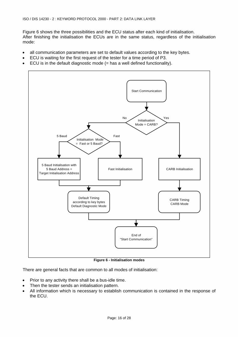
Figure 6 shows the three possibilities and the ECU status after each kind of initialisation. After finishing the initialisation the ECUs are in the same status, regardless of the initialisation mode: • all communication parameters are set to default values according to the key bytes. • ECU is waiting for the first request of the tester for a time period of P3. • ECU is in the default diagnostic mode (= has a well defined functionality).
Start Communication
Initialisation Mode = CARB?
Initialisation Mode = Fast or 5 Baud?
5 Baud Initialisation with 5 Baud Address =
Target Initialisation AddressFast Initialisation CARB Initialisation
End of "Start Communication"
Default Timing according to key bytes
Default Diagnostic Mode
CARB Timing CARB Mode
YesNo
5 Baud Fast
Figure 6 - Initialisation modes
There are general facts that are common to all modes of initialisation: • Prior to any activity there shall be a bus-idle time. • Then the tester sends an initialisation pattern. • All information which is necessary to establish communication is contained in the response of
the ECU.
ISO / DIS 14230 - 2 : KEYWORD PROTOCOL 2000 - PART 2: DATA LINK LAYER
Page: 17 of 28
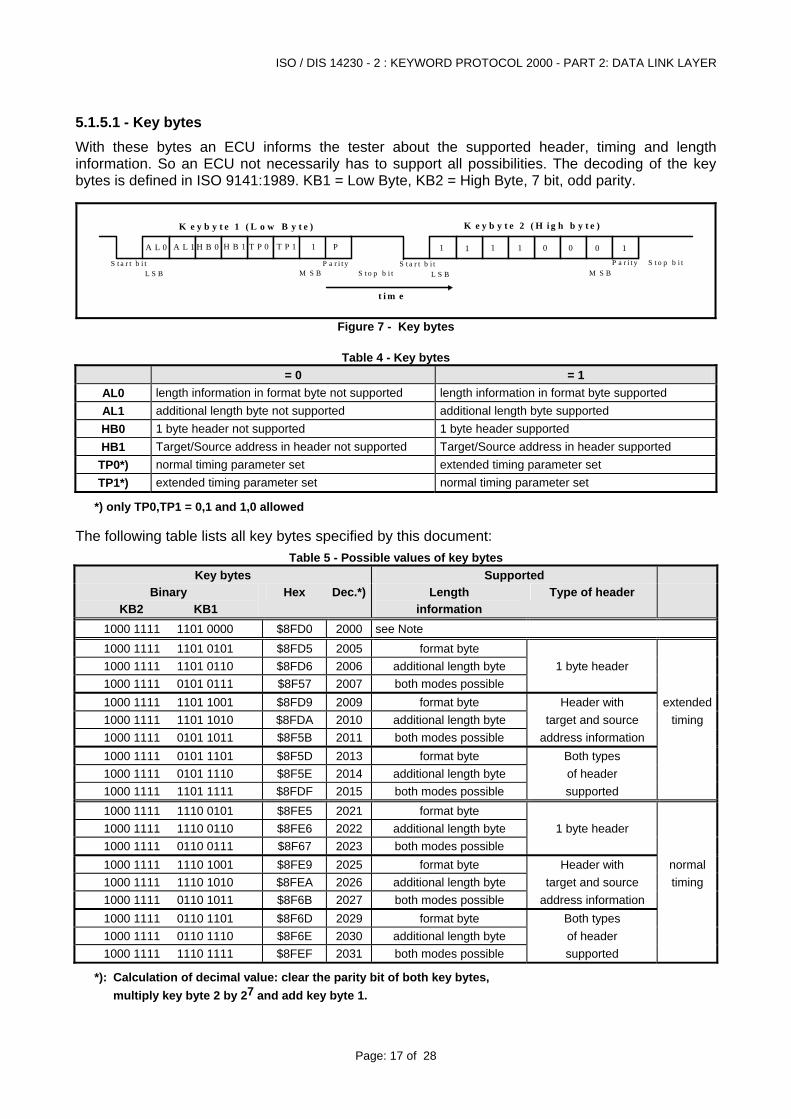
5.1.5.1 - Key bytes With these bytes an ECU informs the tester about the supported header, timing and length information. So an ECU not necessarily has to support all possibilities. The decoding of the key bytes is defined in ISO 9141:1989. KB1 = Low Byte, KB2 = High Byte, 7 bit, odd parity.
T P 1 1 1 1 1 1
K e y b y t e 1 ( L o w B y t e ) K e y b y t e 2 ( H i g h b y t e )
S t a r t b i tS t o p b i t
P a r i t y S t a r t b i t P a r i t y S t o p b i t
A L 0 A L 1 H B 0 H B 1 0 0 0 1PT P 0
L S B M S B L S B M S B
t i m e
Figure 7 - Key bytes
Table 4 - Key bytes = 0 = 1
length information in format byte not supported length information in format byte supported AL0 additional length byte not supported additional length byte supported AL1 1 byte header not supported 1 byte header supported HB0 Target/Source address in header not supported Target/Source address in header supported HB1 normal timing parameter set extended timing parameter set TP0*) extended timing parameter set normal timing parameter set TP1*)
*) only TP0,TP1 = 0,1 and 1,0 allowed The following table lists all key bytes specified by this document:
Table 5 - Possible values of key bytes Key bytes Supported
Binary Hex Dec.*) Length Type of header KB2 KB1 information
1000 1111 1101 0000 $8FD0 2000 see Note 1000 1111 1101 0101 $8FD5 2005 format byte 1000 1111 1101 0110 $8FD6 2006 additional length byte 1 byte header 1000 1111 0101 0111 $8F57 2007 both modes possible 1000 1111 1101 1001 $8FD9 2009 format byte Header with extended1000 1111 1101 1010 $8FDA 2010 additional length byte target and source timing 1000 1111 0101 1011 $8F5B 2011 both modes possible address information 1000 1111 0101 1101 $8F5D 2013 format byte Both types 1000 1111 0101 1110 $8F5E 2014 additional length byte of header 1000 1111 1101 1111 $8FDF 2015 both modes possible supported 1000 1111 1110 0101 $8FE5 2021 format byte 1000 1111 1110 0110 $8FE6 2022 additional length byte 1 byte header 1000 1111 0110 0111 $8F67 2023 both modes possible 1000 1111 1110 1001 $8FE9 2025 format byte Header with normal1000 1111 1110 1010 $8FEA 2026 additional length byte target and source timing 1000 1111 0110 1011 $8F6B 2027 both modes possible address information 1000 1111 0110 1101 $8F6D 2029 format byte Both types 1000 1111 0110 1110 $8F6E 2030 additional length byte of header 1000 1111 1110 1111 $8FEF 2031 both modes possible supported
*): Calculation of decimal value: clear the parity bit of both key bytes, multiply key byte 2 by 27 and add key byte 1.
ISO / DIS 14230 - 2 : KEYWORD PROTOCOL 2000 - PART 2: DATA LINK LAYER
Page: 18 of 28
Note: With value 2000D, the ECU does not give information about which options of the standard are supported. These options concern use of normal or extended timing, additional length byte, header with or without address information. In case of 5 baud initialisation the tester should know what options are implemented. In case of fast initialisation the use of header and length byte will be the same as in the StartCommunication service positive response of the ECU.
5.1.5.2 - Initialisation with 5 Baud address word
5.1.5.2.1 - CARB initialisation For CARB purposes 5 baud initialisation is used only. It is a functional initialisation. Description see ISO 14230 KWP 2000 Part 4: Requirements For Emission Related Systems or ISO 9141-2. Messages are send to all emission related ECUs.
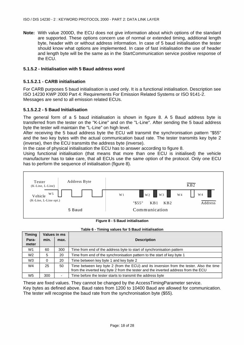
5.1.5.2.2 - 5 Baud Initialisation The general form of a 5 baud initialisation is shown in figure 8. A 5 Baud address byte is transferred from the tester on the "K-Line" and on the "L-Line". After sending the 5 baud address byte the tester will maintain the "L-Line" on high level. After receiving the 5 baud address byte the ECU will transmit the synchronisation pattern "$55" and the two key bytes with the actual communication baud rate. The tester transmits key byte 2 (inverse), then the ECU transmits the address byte (inverse). In the case of physical initialisation the ECU has to answer according to figure 8. Using functional initialisation (that means that more than one ECU is initialised) the vehicle manufacturer has to take care, that all ECUs use the same option of the protocol. Only one ECU has to perform the sequence of initialisation (figure 8).
Vehicle
Tester Address Byte
"$55" KB1 KB2 Address
KB2
5 Baud Communication
(K-Line, L-Line)
(K-Line, L-Line opt.)
W 1 W 2 W 3 W 4 W 4W 5
Figure 8 - 5 Baud initialisation
Table 6 - Timing values for 5 Baud initialisation Timing Values in ms Para- min. max. Description meter
W1 60 300 Time from end of the address byte to start of synchronisation pattern W2 5 20 Time from end of the synchronisation pattern to the start of key byte 1 W3 0 20 Time between key byte 1 and key byte 2 W4 25 50 Time between key byte 2 (from the ECU) and its inversion from the tester. Also the time
from the inverted key byte 2 from the tester and the inverted address from the ECU W5 300 - Time before the tester starts to transmit the address byte
These are fixed values. They cannot be changed by the AccessTimingParameter service. Key bytes as defined above. Baud rates from 1200 to 10400 Baud are allowed for communication. The tester will recognise the baud rate from the synchronisation byte ($55).
ISO / DIS 14230 - 2 : KEYWORD PROTOCOL 2000 - PART 2: DATA LINK LAYER
Page: 19 of 28
5.1.5.2.3 - Functional initialisation With this procedure a group of ECUs is initialised. Address bytes which define a functional group of ECUs are listed in Appendix A. Other manufacturer defined functional address bytes according to ISO 9141:1989 (i.e. odd parity) are possible. Functional addressing is only possible, if all ECUs of a functional group use equal baud rates. CARB initialisation is a special case of functional addressing.
5.1.5.2.4 - Physical initialisation With this procedure only a single ECU is initialised. 5 Baud initialisation address is according to ISO 9141:1989. Odd Parity is used. Address bytes are manufacturer controlled.
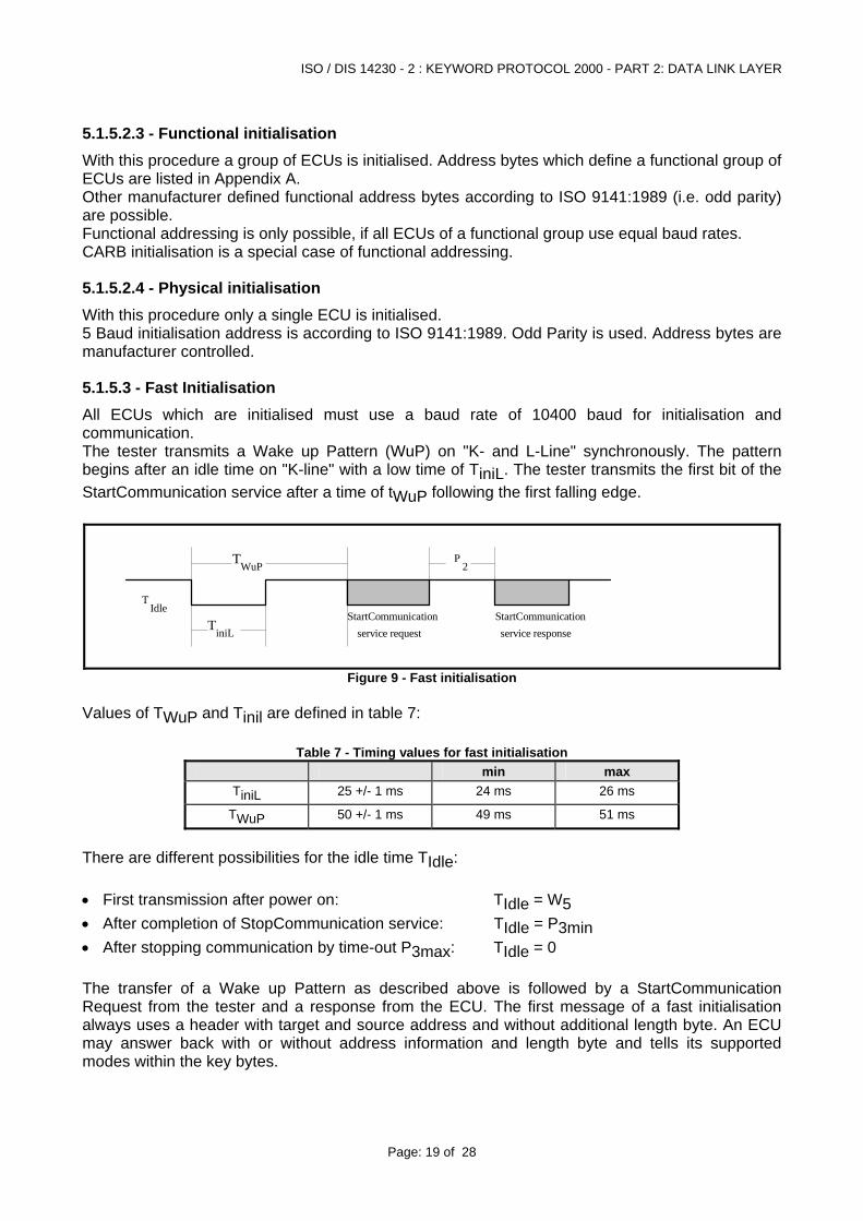
5.1.5.3 - Fast Initialisation All ECUs which are initialised must use a baud rate of 10400 baud for initialisation and communication. The tester transmits a Wake up Pattern (WuP) on "K- and L-Line" synchronously. The pattern begins after an idle time on "K-line" with a low time of TiniL. The tester transmits the first bit of the StartCommunication service after a time of tWuP following the first falling edge.
TiniLStartCommunication
TWuP
TIdle
service requestStartCommunicationservice response
P2
Figure 9 - Fast initialisation Values of TWuP and Tinil are defined in table 7:
Table 7 - Timing values for fast initialisation min max
TiniL 25 +/- 1 ms 24 ms 26 ms
TWuP 50 +/- 1 ms 49 ms 51 ms
There are different possibilities for the idle time TIdle: • First transmission after power on: TIdle = W5 • After completion of StopCommunication service: TIdle = P3min • After stopping communication by time-out P3max: TIdle = 0 The transfer of a Wake up Pattern as described above is followed by a StartCommunication Request from the tester and a response from the ECU. The first message of a fast initialisation always uses a header with target and source address and without additional length byte. An ECU may answer back with or without address information and length byte and tells its supported modes within the key bytes.
ISO / DIS 14230 - 2 : KEYWORD PROTOCOL 2000 - PART 2: DATA LINK LAYER
Page: 20 of 28
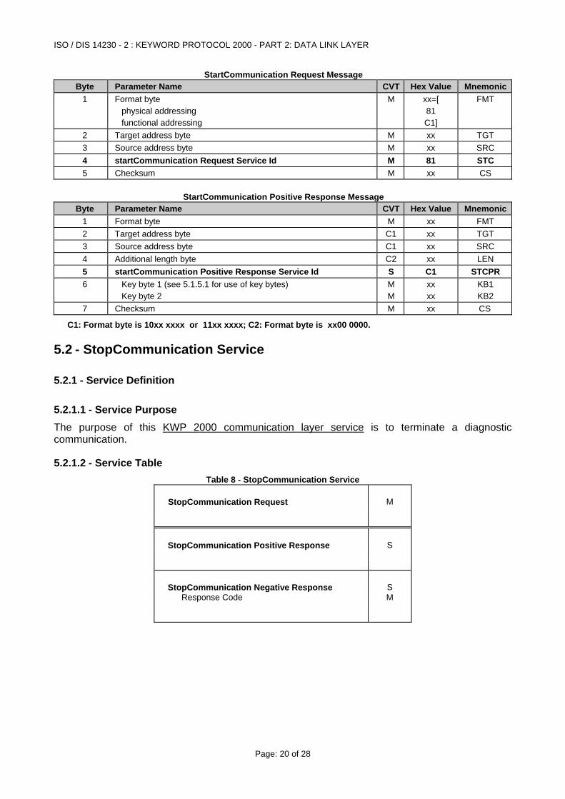
StartCommunication Request Message Byte Parameter Name CVT Hex Value Mnemonic
1 Format byte physical addressing functional addressing
M xx=[ 81 C1]
FMT
2 Target address byte M xx TGT 3 Source address byte M xx SRC 4 startCommunication Request Service Id M 81 STC 5 Checksum M xx CS
StartCommunication Positive Response Message
Byte Parameter Name CVT Hex Value Mnemonic1 Format byte M xx FMT 2 Target address byte C1 xx TGT 3 Source address byte C1 xx SRC 4 Additional length byte C2 xx LEN 5 startCommunication Positive Response Service Id S C1 STCPR 6 Key byte 1 (see 5.1.5.1 for use of key bytes)
Key byte 2 M M
xx xx
KB1 KB2
7 Checksum M xx CS
C1: Format byte is 10xx xxxx or 11xx xxxx; C2: Format byte is xx00 0000.
5.2 - StopCommunication Service
5.2.1 - Service Definition
5.2.1.1 - Service Purpose The purpose of this KWP 2000 communication layer service is to terminate a diagnostic communication.
5.2.1.2 - Service Table Table 8 - StopCommunication Service
StopCommunication Request M
StopCommunication Positive Response S
StopCommunication Negative Response S Response Code M
ISO / DIS 14230 - 2 : KEYWORD PROTOCOL 2000 - PART 2: DATA LINK LAYER
Page: 21 of 28
5.2.1.3 - Service Procedure Upon receiving a StopCommunication indication primitive, the ECU shall check if the current conditions allow to terminate this communication. In this case the server shall perform all actions necessary to terminate this communication. If it is possible to terminate the communication, the ECU shall issue a StopCommunication response primitive with the positive response parameters selected, before the communication is terminated. If the communication cannot be terminated by any reason, the server shall issue a StopCommunication response primitive with the negative response parameter selected.
5.2.2 - Implementation StopCommunication Request Message
Byte Parameter Name CVT Hex Value Mnemonic1 Format byte M xx FMT 2 Target address byte C1 xx TGT 3 Source address byte C1 xx SRC 4 Additional length byte C2 xx LEN 5 stopCommunication Request Service Id M 82 SPC 6 Checksum M xx CS
StopCommunication Positive Response Message
Byte Parameter Name CVT Hex Value Mnemonic1 Format byte M xx FMT 2 Target address byte C1 xx TGT 3 Source address byte C1 xx SRC 4 Additional length byte C2 xx LEN 5 stopCommunication Positive Response Service Id S C2 SPCPR 6 Checksum M xx CS
StopCommunication Negative Response Message
Byte Parameter Name CVT Hex Value Mnemonic1 Format byte M xx FMT 2 Target address byte C1 xx TGT 3 Source address byte C1 xx SRC 4 Additional length byte C2 xx LEN 5 negative Response Service Id S 7F SPCNR 6 stopCommunication Request Service Identification S 82 STC 7 ResponseCode*) = generalReject M xx = 10 RC 8 Checksum M xx CS
*) Other response codes possible, see Keyword Protocol 2000 - Part 3: Implementation C1: Format byte is 10xx xxxx or 11xx xxxx C2: Format byte is xx00 0000.
ISO / DIS 14230 - 2 : KEYWORD PROTOCOL 2000 - PART 2: DATA LINK LAYER
Page: 22 of 28
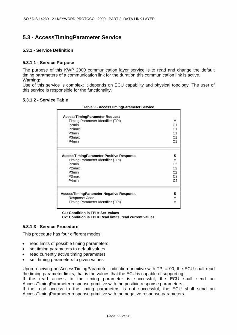
5.3 - AccessTimingParameter Service
5.3.1 - Service Definition
5.3.1.1 - Service Purpose The purpose of this KWP 2000 communication layer service is to read and change the default timing parameters of a communication link for the duration this communication link is active. Warning: Use of this service is complex; it depends on ECU capability and physical topology. The user of this service is responsible for the functionality.
5.3.1.2 - Service Table Table 9 - AccessTimingParameter Service
AccessTimingParameter Request Timing Parameter Identifier (TPI) M P2min C1 P2max C1 P3min C1 P3max C1 P4min C1
AccessTimingParameter Positive Response S Timing Parameter Identifier (TPI) M P2min C2 P2max C2 P3min C2 P3max C2 P4min C2
AccessTimingParameter Negative Response S Response Code M Timing Parameter Identifier (TPI) M
C1: Condition is TPI = Set values C2: Condition is TPI = Read limits, read current values
5.3.1.3 - Service Procedure This procedure has four different modes: • read limits of possible timing parameters • set timing parameters to default values • read currently active timing parameters • set timing parameters to given values Upon receiving an AccessTimingParameter indication primitive with TPI = 00, the ECU shall read the timing parameter limits, that is the values that the ECU is capable of supporting. If the read access to the timing parameter is successful, the ECU shall send an AccessTimingParameter response primitive with the positive response parameters. If the read access to the timing parameters is not successful, the ECU shall send an AccessTimingParameter response primitive with the negative response parameters.
ISO / DIS 14230 - 2 : KEYWORD PROTOCOL 2000 - PART 2: DATA LINK LAYER
Page: 23 of 28
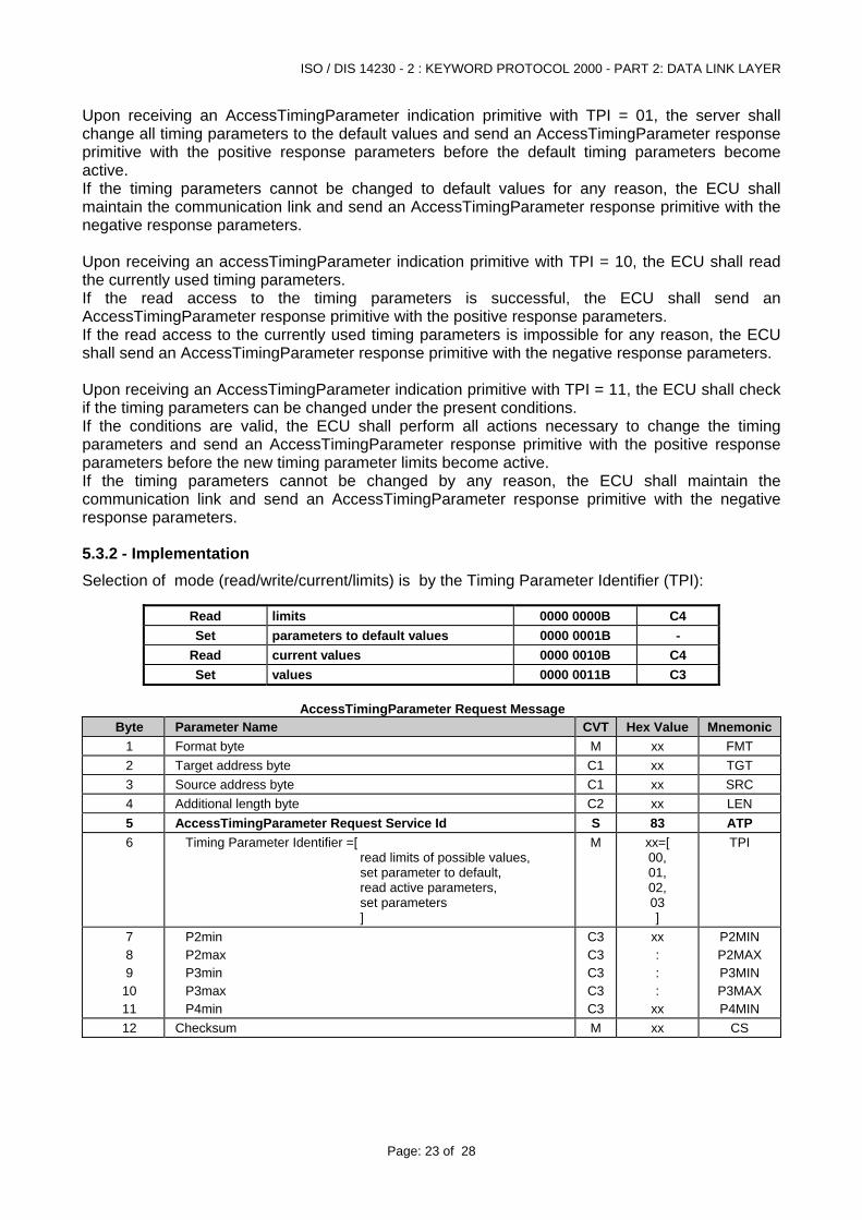
Upon receiving an AccessTimingParameter indication primitive with TPI = 01, the server shall change all timing parameters to the default values and send an AccessTimingParameter response primitive with the positive response parameters before the default timing parameters become active. If the timing parameters cannot be changed to default values for any reason, the ECU shall maintain the communication link and send an AccessTimingParameter response primitive with the negative response parameters. Upon receiving an accessTimingParameter indication primitive with TPI = 10, the ECU shall read the currently used timing parameters. If the read access to the timing parameters is successful, the ECU shall send an AccessTimingParameter response primitive with the positive response parameters. If the read access to the currently used timing parameters is impossible for any reason, the ECU shall send an AccessTimingParameter response primitive with the negative response parameters. Upon receiving an AccessTimingParameter indication primitive with TPI = 11, the ECU shall check if the timing parameters can be changed under the present conditions. If the conditions are valid, the ECU shall perform all actions necessary to change the timing parameters and send an AccessTimingParameter response primitive with the positive response parameters before the new timing parameter limits become active. If the timing parameters cannot be changed by any reason, the ECU shall maintain the communication link and send an AccessTimingParameter response primitive with the negative response parameters.
5.3.2 - Implementation Selection of mode (read/write/current/limits) is by the Timing Parameter Identifier (TPI):
Read limits 0000 0000B C4 Set parameters to default values 0000 0001B -
Read current values 0000 0010B C4 Set values 0000 0011B C3
AccessTimingParameter Request Message
Byte Parameter Name CVT Hex Value Mnemonic1 Format byte M xx FMT 2 Target address byte C1 xx TGT 3 Source address byte C1 xx SRC 4 Additional length byte C2 xx LEN 5 AccessTimingParameter Request Service Id S 83 ATP 6 Timing Parameter Identifier =[
read limits of possible values, set parameter to default, read active parameters, set parameters ]
M xx=[ 00, 01, 02, 03 ]
TPI
7 8 9
10 11
P2min P2max P3min P3max P4min
C3C3C3C3C3
xx : : :
xx
P2MIN P2MAX P3MIN P3MAX P4MIN
12 Checksum M xx CS
ISO / DIS 14230 - 2 : KEYWORD PROTOCOL 2000 - PART 2: DATA LINK LAYER
Page: 24 of 28
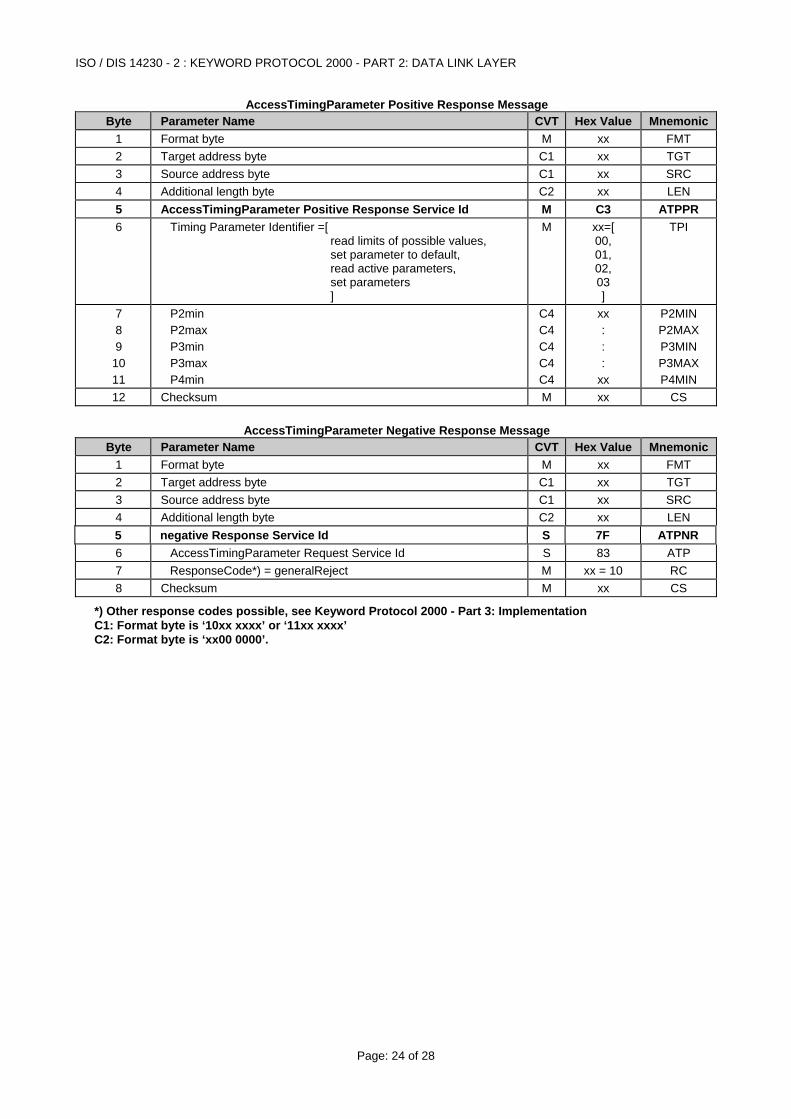
AccessTimingParameter Positive Response Message Byte Parameter Name CVT Hex Value Mnemonic
1 Format byte M xx FMT 2 Target address byte C1 xx TGT 3 Source address byte C1 xx SRC 4 Additional length byte C2 xx LEN 5 AccessTimingParameter Positive Response Service Id M C3 ATPPR 6 Timing Parameter Identifier =[
read limits of possible values, set parameter to default, read active parameters, set parameters ]
M xx=[ 00, 01, 02, 03 ]
TPI
7 8 9
10 11
P2min P2max P3min P3max P4min
C4C4C4C4C4
xx : : :
xx
P2MIN P2MAX P3MIN P3MAX P4MIN
12 Checksum M xx CS
AccessTimingParameter Negative Response Message Byte Parameter Name CVT Hex Value Mnemonic
1 Format byte M xx FMT 2 Target address byte C1 xx TGT 3 Source address byte C1 xx SRC 4 Additional length byte C2 xx LEN 5 negative Response Service Id S 7F ATPNR 6 AccessTimingParameter Request Service Id S 83 ATP 7 ResponseCode*) = generalReject M xx = 10 RC 8 Checksum M xx CS
*) Other response codes possible, see Keyword Protocol 2000 - Part 3: Implementation C1: Format byte is ‘10xx xxxx’ or ‘11xx xxxx’ C2: Format byte is ‘xx00 0000’.
ISO / DIS 14230 - 2 : KEYWORD PROTOCOL 2000 - PART 2: DATA LINK LAYER
Page: 25 of 28
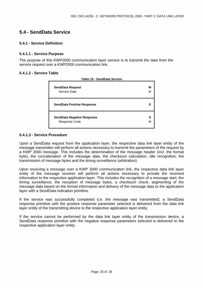
5.4 - SendData Service
5.4.1 - Service Definition
5.4.1.1 - Service Purpose The purpose of this KWP2000 communication layer service is to transmit the data from the service request over a KWP2000 communication link.
5.4.1.2 - Service Table Table 10 - SendData Service
SendData Request M Service Data M
SendData Positive Response S
SendData Negative Response S Response Code M
5.4.1.3 - Service Procedure
Upon a SendData request from the application layer, the respective data link layer entity of the message transmitter will perform all actions necessary to transmit the parameters of the request by a KWP 2000 message. This includes the determination of the message header (incl. the format byte), the concatenation of the message data, the checksum calculation, idle recognition, the transmission of message bytes and the timing surveillance (arbitration). Upon receiving a message over a KWP 2000 communication link, the respective data link layer entity of the message receiver will perform all actions necessary to provide the received information to the respective application layer. This includes the recognition of a message start, the timing surveillance, the reception of message bytes, a checksum check, segmenting of the message data based on the format information and delivery of the message data to the application layer with a SendData indication primitive. If the service was successfully completed (i.e. the message was transmitted), a SendData response primitive with the positive response parameter selected is delivered from the data link layer entity of the transmitting device to the respective application layer entity. If the service cannot be performed by the data link layer entity of the transmission device, a SendData response primitive with the negative response parameters selected is delivered to the respective application layer entity.
ISO / DIS 14230 - 2 : KEYWORD PROTOCOL 2000 - PART 2: DATA LINK LAYER
Page: 26 of 28
6 - Error Handling
6.1 - Start Communication service If the tester detects an error during the "StartCommunication Service" either by timing or by the bit stream, then the tester will wait for a period of W5 before beginning the process again (starting with the wake up pattern). If an ECU detects an error in the sequence from the tester then it shall be immediately prepared to recognise another "StartCommunication Service". Both tester and ECU are required to recognise failure to comply with maximum timing values. Minimum timing value transgressions need not be detected but are likely to cause bit stream errors.
6.2 - Mainstream Communications It is allowed but not required that the tester and ECU(s) may monitor their own messages. This creates four areas where error handling can be defined. Each is discussed separately below and diagramatically represented in figure 10.
6.3 - ECU detected Tester transmission error The ECU shall check each message by its checksum and number of bytes received before P2max elapses. If either is in error then the ECU shall send no response and will internally ignore the whole message. The ECU is not required to check for other timing transgressions but may do so. Again no response should be given. The ECU may detect other errors in the format or content of messages, but which satisfy the checksum and length requirements. In these cases, in order that the tester be aware that there is not a simple communications problem, the ECU should respond with the appropriate negative response message at least.
6.4 - Tester detected error in vehicle response A single request may result in a single response from a single ECU or in multiple responses from several modules. The tester should check that all responses are correct both in terms of length and checksum as above. In case of an error or no response during P2max it should retransmit the original message twice (i.e. three transmissions in total) before considering more severe error recovery processes. The application shall be informed of errors on the communication link. This will allow the application to make the appropriate action.
6.5 - ECU detected error in ECU response The ECU may detect a difference between what it transmitted and what was detected on the "K - Line”. In this case it may either do nothing or retry the transmission within a period of P2 after bus activity ceasing. This allows various bus management methods to be adopted.
6.6 - Tester detected error in tester transmission. The tester may detect a difference between what it transmitted and what it detected on the "K - Line”. In this case it shall transmit the whole message and give an error report to the application. After the time P2max the tester may retransmit the request.
ISO / DIS 14230 - 2 : KEYWORD PROTOCOL 2000 - PART 2: DATA LINK LAYER
Page: 27 of 28
Request received?
P3max expired?
CS, Length error?
Stop Comm.
Service supported?
Form & Content o.k?
Error recovery? Too busy?Request not
supported
Request accepted
ECU busy
Build response Add Header &
Checksum Send Response
Add Header & Checksum
Send Request
Response Received?
P2max expired?
CS, Length error?
3 Attempts?
Response: ECU busy?
P2max expired?
Response: Request o.k?
Data o.k?
Continue Application
Build requestError Handler
Application Communication Application
Tester ECU
N
N
N
N
N
N
N N
N
N
Y YN
N
N
Y
Y
Y YN N
Y
Y
Y
Y Y
Y
Y Y
Y
Figure 10 - Error Handling
ISO / DIS 14230 - 2 : KEYWORD PROTOCOL 2000 - PART 2: DATA LINK LAYER
Page: 28 of 28
Appendix A - ECU/Tester Addresses for 5 Baud Initialisation This section is part of the International Standard. Physical Addresses According to ISO 9141:1989 Address byte consists of 1 start bit, 7 bit address, 1 parity bit (odd parity), at least 1 stop bit. Addresses are controlled by car manufacturers. Functional Addresses Addresses with values < $80 are reserved for future standardisation. Addresses with values > $80 are manufacturer specific. Appendix B - ECU/Tester Addresses for fast initialisation This section is for information only. Addresses may be the same as used for 5 Baud initialisation (see Appendix A) or according to SAE J2178 Part 1.
Powertrain Controllers Hex Integration/Manufacturer Expansion 00 - 0F Engine Controllers 10 - 17 Transmission Controllers 18 - 1F Chassis Controllers Integration/Manufacturer Expansion 20 - 27 Brake Controllers 28 - 2F Steering Controllers 30 - 37 Suspension Controllers 38 - 3F Body Controllers Integration/Manufacturer Expansion 40 - 57 Restraints 58 - 5F Driver Information/Displays 60 - 6F Lightning 70 - 7F Entertainment/Audio 80 - 8F Personal Communication 90 - 97 Climate Control (HVAC) 98 - 9F Convenience (Doors,Seats,Windows,etc) A0 - BF Security C0 - C7 Future Expansion: C8 - CF Manufacturer Specific D0 - EF Off-Board Tester/Diagnostic Tools: F0 - FD All Nodes FE Null Nodes FF