Embed Size (px)
Citation preview
FOLDABLE COMPOSITE STRUCTURES
J.C.H. Yee and S. Pellegrino1
Department of Engineering, University of CambridgeTrumpington Street, Cambridge CB2 1PZ, UK
Abstract This paper presents a study of the folding of a new self-powered, self-latching tubehinge for deployable structures. This hinge is made by cutting three parallel slots in a thin-walled carbon fibre reinforced plastic (CFRP) tube, thus leaving three tape springs connectingthe two ends of the tube.
Keywords: CFRP, deployable structures, tape springs
Introduction and Background
There is a growing trend in the aerospace industry towards simpler, cheaper and morereliable deployable structures. Hence, research is being carried out into structural con-cepts that can provide at the same time enhanced levels of functionality in comparisonwith previous designs for deployable booms, solar arrays, etc. and also require a smallernumber of separate parts. One approach that is being pursued is to combine severalfunctions in each structural element, and also to reduce the number and complexity ofseparate operations involved in constructing that element.
An example of this new approach is a self-powered, self-latching tube hinge madeby cutting three parallel slots in a thin-walled carbon fibre reinforced plastic (CFRP)tube with circular cross-section. The slots divide the tube into three strips that aretransversally curved; these strips —known as tape springs— can be flattened transver-sally and then bent longitudinally to form a localised fold, as shown in Figure 1. Thisstructure is a replacement for a traditional pin-and-clevis hinge and is currently beingconsidered for several space missions.
Tube hinges are designed such that their deformation during folding is entirelyelastic. The uncut tube ends remain essentially undeformed, hence the deformationis almost entirely in the tape springs. The folding of a tube hinge can be simplydescribed in terms of the inner tape springs deforming in opposite sense bending andthe two outer tape springs deforming in equal sense bending. Here equal sense bendingindicates that the bent tape spring has the same convexity as the straight one, seeFig. 2(a); in this case the edges of the tape spring are under compression. Conversely,opposite-sense bending indicates that the bent tape spring has opposite convexity tothe bent one, Fig. 2(b), in which case the edges of the tape spring are under tension.
1Corresponding author: [email protected]
1
Figure 1: CFRP tube hinge (unfolded, folded 110◦, folded 180◦).
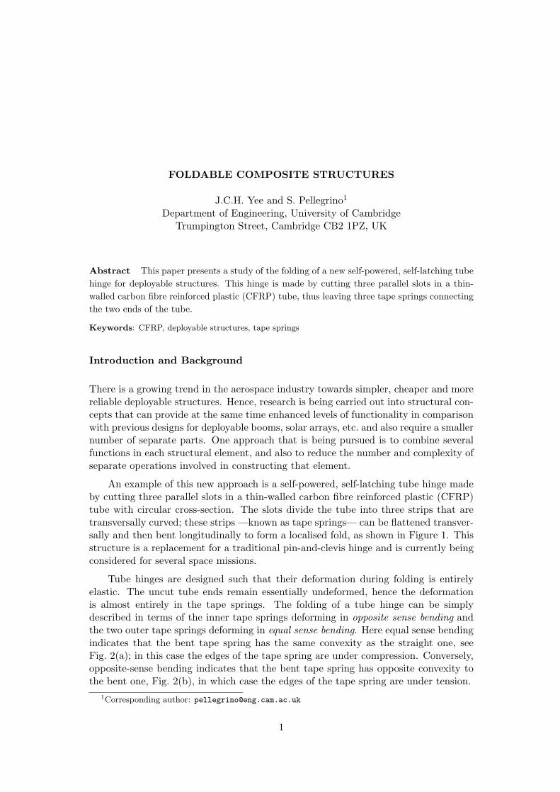
When an initially straight tape spring is subject to gradually increasing equaland opposite end rotations, initially it takes a uniform longitudinally curved shape.Its moment-rotation relationship is linear for sufficiently small rotations. If the tapespring is subject to opposite-sense bending, as the end rotations are increased the tapespring suddenly snaps and forms an elastic fold that is approximately straight in thetransverse direction and has approximately uniform longitudinal curvature, Fig. 2(b).Then, if the rotations are further increased, the arc-length of the fold increases whileits curvature remains constant. If, however, the tape spring is subject to equal-sense
(b) Opposite sense bending(a) Equal sense bending
Figure 2: Two different ways of folding a tape spring.
bending, it deforms by gradually twisting over two adjacent, but separate regions whoselengths grow until the two folds merge into a single, localised fold, Fig. 2(a). Oncethis single fold has formed, further increasing the end rotation results —again— onlyin an increase of the arc-length of the fold region.
A folded tape spring has a natural tendency to deploy, thus resuming its straightconfiguration, and the combination of three tape springs in a tube hinge has the effectof increasing the deployment moment of the hinge, as well as increasing the momentthat the hinge can resist without folding.
Tape springs made of isotropic materials (typically beryllium-copper or steel) have
2
been used for many years (Rimrott 1965). Rimrott (1970) and later Calladine (1988)have proposed an analytical model for predicting the longitudinal radius, r, of theuniformly curved region at the centre of an isotropic, folded tape spring with transverseradius of curvature R. An extension of this model to orthotropic shells of thickness tby Yee and Pellegrino (2003a) gives
r =√D11
D22R (1)
whereD11, D22 are the bending stiffnesses of the shell in the longitudinal and transversedirections, respectively. This result is valid for both equal- and opposite-sense bendingof the tape spring. The longitudinal strain in this curved region can be estimated from
εx = ±√D22
D11
t
2R(2)
where the sign is + for equal-sense bending and z = +t/2, or for opposite-sense andz = −t/2; the sign is − for equal-sense bending and z = −t/2, or for opposite-senseand z = +t/2. And the transverse strain from
εy = ∓ t
2R(3)
where the sign is − at z = +t/2 and + at z = −t/2, regardless of the sense of bending.This paper considers a particular tube hinge design, which requires the tape springs
to fold so tightly that they have to operate close to failure. For this design, the paperpresents a finite element analysis of the peak strains induced by the folding process.The geometric and material properties of the hinge are presented in the next section.Then a series of finite-element simulations of the folding of a single tape spring andof a tube hinge. The predictions obtained from the simulations are compared withpredictions from Equations 1, 2 and 3 in the section Results. A Discussion concludesthe paper.
Geometrical and Material Properties
The tube hinges considered in this paper are 82 mm long and have a circular cross-section with radius R = 6.5 mm. They are made from woven T300/913 prepregs(913C-814-40%, produced by Hexcel, which have 60% fibre content). The materialproperties of this prepreg are given in Table 1. In the central section there are three50 mm long tape springs, each subtending an angle of 70◦, which leaves 50◦ for eachslot. The slots are machined with a radius of 3 mm at both ends.
One-ply and two-ply laminates are considered, corresponding to tube thicknessesof 0.27 mm and 0.47 mm. Yee and Pellegrino (2003b) have found that when T300/913[0,90] laminates are folded in a direction that is perpendicular to one set of fibres andparallel to the other set, a one-ply laminate fails when it is subjected to a peak bendingstrain of about 2.7% in the direction of the fibres, whereas the two-ply laminate fails
3
at a bending strain of about 2.0%. On the other hand, when they are folded at 45◦
to the fibres, these laminates fail at peak strains around 5%, the corresponding fibrestrains being around 2.5%. On this basis, it will be assumed that a one-ply tube hingecan survive bending strains along the fibres of up to 2.5% whereas for a two-ply hingethe bending strain limit is 2.0 %.
Table 1: Properties of 913C-814-40% prepregsElastic Moduli, E11 ≈ E22 (GPa) 46.0Shear Modulus, G12 (GPa) 4.5Poisson’s ratio, ν12 = ν21 0.065
Simulation of Folding Process
Detailed simulations of the folding of a single tape spring and of a complete tubehinge, consisting of three identical tape springs, were carried out with the ABAQUS(2001)package. Both one-ply and two-ply tape springs were analysed, and the linear-elastic material properties presented in Table 1 were assumed.
These simulations allow us to compare the deformation of a single tape springwith that of a hinge that is part of a tube hinge, so that we can better understand thestructural behaviour of the actual tube hinge.
Element Choice
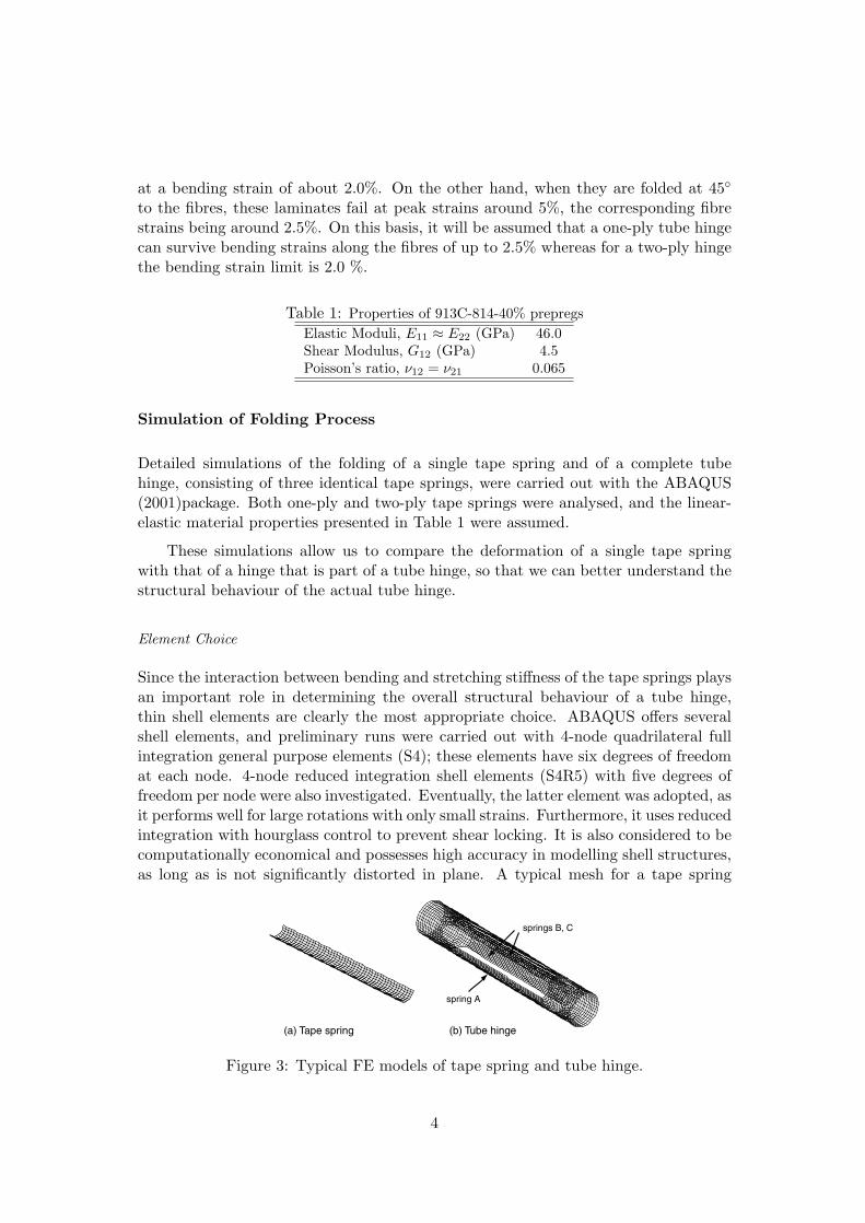
Since the interaction between bending and stretching stiffness of the tape springs playsan important role in determining the overall structural behaviour of a tube hinge,thin shell elements are clearly the most appropriate choice. ABAQUS offers severalshell elements, and preliminary runs were carried out with 4-node quadrilateral fullintegration general purpose elements (S4); these elements have six degrees of freedomat each node. 4-node reduced integration shell elements (S4R5) with five degrees offreedom per node were also investigated. Eventually, the latter element was adopted, asit performs well for large rotations with only small strains. Furthermore, it uses reducedintegration with hourglass control to prevent shear locking. It is also considered to becomputationally economical and possesses high accuracy in modelling shell structures,as long as is not significantly distorted in plane. A typical mesh for a tape spring
(a) Tape spring (b) Tube hinge
spring A
springs B, C
Figure 3: Typical FE models of tape spring and tube hinge.
4
involved 200 elements lengthwise by 30 elements widthwise. The mesh for a completetape tube hinge had a similar mesh density and hence the number of elements wasproportionally larger.
Simulation Techniques
The multiple point constraints (MPC ) option was used to define the boundary condi-tions. For both the tape spring and the tube hinge models, the nodes on either endwere tied to a MPC node, located at the centroid of the end cross section, throughrigid beam elements. The main reason for locating the MPC nodes at the centroid isbecause the structure will be under pure bending when rotations are applied at theends.
The three tape springs that constitute a tube hinge interact during the foldingprocess, hence contact between these tape springs needs to be suitably modelled.ABAQUS defines the contact conditions between two bodies using a strict “master-slave” algorithm. The (*CONTACT PAIR) option needs to be specified for the twodeformable surfaces, one of which is defined as the master surface and the other as theslave surface. In addition, the INTERACTION parameter is used to associate the con-tact pairs being defined with a surface interaction model, such as friction. The SMALLSLIDING parameter was chosen, instead of FINITE SLIDING, to achieve greater sen-sitivity to local initial gaps at the interface, caused by mismatch in the discretization ofthe meshed surfaces that come into contact. The SLIDING parameter sets up a slavenode that interacts with the same region of the master surface throughout the analysis,despite the large displacements that occur during the simulation. The SURFACE BE-HAVIOR parameter was set to the default, PRESSURE-OVERCLOSURE=HARD,which provides arbitrarily large contact forces as soon as the surfaces are in contact.
After having unsuccessfully attempted to use a default contact definition, a sym-metric master-slave approach was adopted, i.e. two sets of contact pairs were definedfor the same two surfaces, switching the roles of master and slave between the two tapesprings. Despite involving additional computations, this approach provided improvedconvergence and accuracy.
A geometrically non-linear (*NLGEOM) incremental analysis was carried outusing the Newton-Raphson solution method, with automatic stabilization providedthrough the STABILIZE function. This solution option automatically introducespseudo-inertia and pseudo-viscous forces at all nodes when an instability is detected.Instead of continuing with the standard quasi-static analysis, ABAQUS automaticallyswitches to a pseudo-dynamic integration of the equations of motion for the structure,thus avoiding numerical singularities. The pseudo viscous forces are calculated basedon the model’s response in the first increment of the analysis step, by assuming that thedissipated energy is a fraction of the strain energy during the first step. This fraction isknown as damping intensity, which has a default value of 2× 10⁻⁴. To attain accurateresults, it is desirable to set this parameter to the lowest value where convergence isstill possible. In most of the analyses presented in this paper the damping intensitywas set to 1 × 10⁻⁸.
5
Results
This section presents the finite element analysis results for both the tape spring andthe tube hinge, and compares the maximum strains and fold radii obtained from thesedetailed analyses with results from Equations 1-3.
Folding of Tape Spring
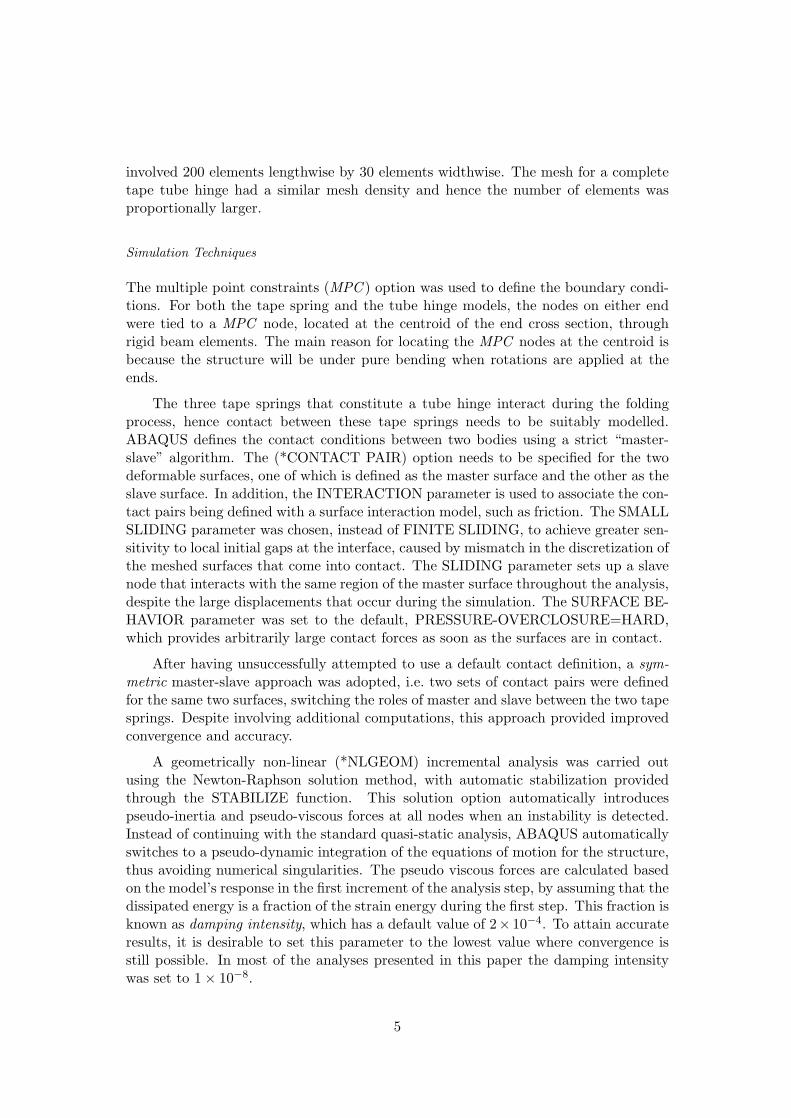
Figure 4 shows a series of snapshots from the folding sequence of a one-ply [±45◦] tapespring subject to opposite-sense bending under monotonically increasing end rotationsof the two MPC nodes. The tape spring has radius R = 6.5 mm and subtends an angleθ = 130◦.
(a) (b) (c) (d)
Figure 4: Folding sequence of tape spring subject to opposite-sense bending.
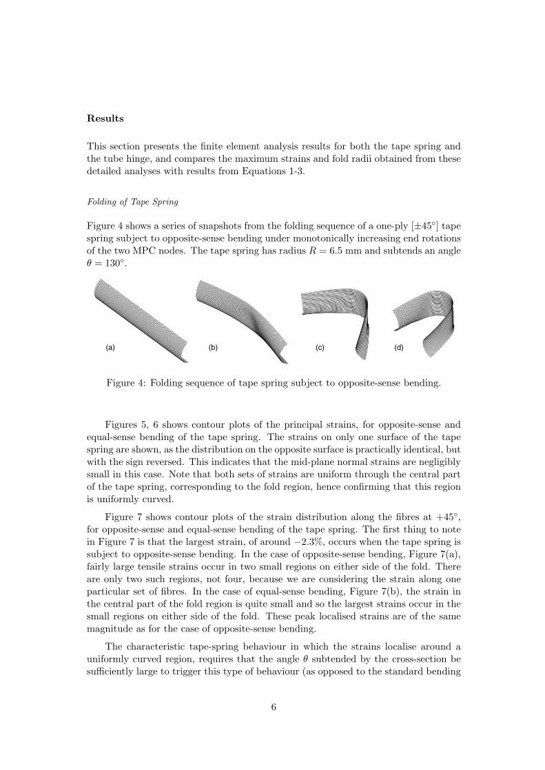
Figures 5, 6 shows contour plots of the principal strains, for opposite-sense andequal-sense bending of the tape spring. The strains on only one surface of the tapespring are shown, as the distribution on the opposite surface is practically identical, butwith the sign reversed. This indicates that the mid-plane normal strains are negligiblysmall in this case. Note that both sets of strains are uniform through the central partof the tape spring, corresponding to the fold region, hence confirming that this regionis uniformly curved.
Figure 7 shows contour plots of the strain distribution along the fibres at +45◦,for opposite-sense and equal-sense bending of the tape spring. The first thing to notein Figure 7 is that the largest strain, of around −2.3%, occurs when the tape spring issubject to opposite-sense bending. In the case of opposite-sense bending, Figure 7(a),fairly large tensile strains occur in two small regions on either side of the fold. Thereare only two such regions, not four, because we are considering the strain along oneparticular set of fibres. In the case of equal-sense bending, Figure 7(b), the strain inthe central part of the fold region is quite small and so the largest strains occur in thesmall regions on either side of the fold. These peak localised strains are of the samemagnitude as for the case of opposite-sense bending.
The characteristic tape-spring behaviour in which the strains localise around auniformly curved region, requires that the angle θ subtended by the cross-section besufficiently large to trigger this type of behaviour (as opposed to the standard bending
6
(a)
(b)
+0.69 %+1.03 %+1.37 %+1.71 %+2.05 %+2.39 %
-2.70 %-2.36 %-2.02 %-1.68 %-1.35 %-1.01 %-0.67 %-0.33 %+0.13 %+0.35 %
Figure 5: Principal strains on surface z = +t/2 of 1-ply [±45◦] tape spring underopposite-sense bending; (a) maximum principal strain; (b) minimum principal strain.
(a)
(b)
+0.69 %+1.03 %+1.37 %+1.71 %+2.05 %+2.39 %
-2.70 %-2.36 %-2.02 %-1.68 %-1.35 %-1.01 %-0.67 %-0.33 %+0.13 %+0.35 %
Figure 6: Principal strains on surface z = +t/2 of 1-ply [±45◦] tape spring underequal-sense bending; (a) maximum principal strain; (b) minimum principal strain.
7
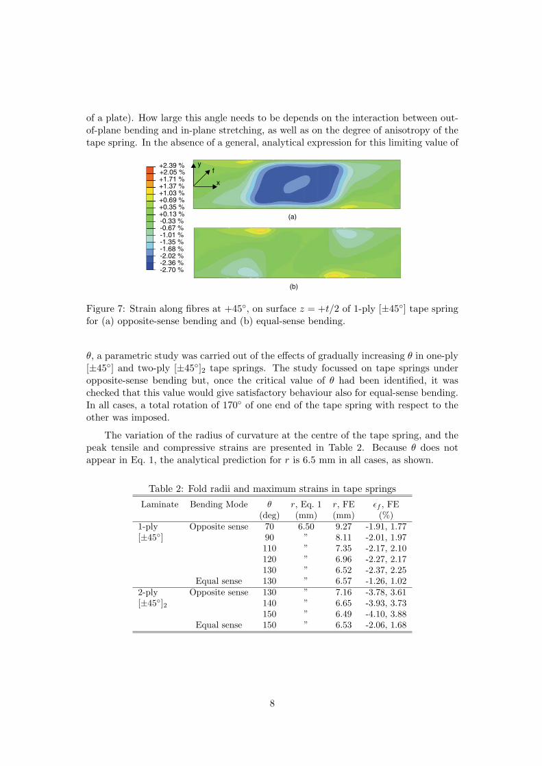
of a plate). How large this angle needs to be depends on the interaction between out-of-plane bending and in-plane stretching, as well as on the degree of anisotropy of thetape spring. In the absence of a general, analytical expression for this limiting value of
(a)
(b)
+0.69 %+1.03 %+1.37 %+1.71 %+2.05 %+2.39 %
-2.70 %-2.36 %-2.02 %-1.68 %-1.35 %-1.01 %-0.67 %-0.33 %+0.13 %+0.35 %
f
x
y
Figure 7: Strain along fibres at +45◦, on surface z = +t/2 of 1-ply [±45◦] tape springfor (a) opposite-sense bending and (b) equal-sense bending.
θ, a parametric study was carried out of the effects of gradually increasing θ in one-ply[±45◦] and two-ply [±45◦]2 tape springs. The study focussed on tape springs underopposite-sense bending but, once the critical value of θ had been identified, it waschecked that this value would give satisfactory behaviour also for equal-sense bending.In all cases, a total rotation of 170◦ of one end of the tape spring with respect to theother was imposed.
The variation of the radius of curvature at the centre of the tape spring, and thepeak tensile and compressive strains are presented in Table 2. Because θ does notappear in Eq. 1, the analytical prediction for r is 6.5 mm in all cases, as shown.
Table 2: Fold radii and maximum strains in tape springs
Laminate Bending Mode θ r, Eq. 1 r, FE εf , FE(deg) (mm) (mm) (%)
1-ply Opposite sense 70 6.50 9.27 -1.91, 1.77[±45◦] 90 ” 8.11 -2.01, 1.97
110 ” 7.35 -2.17, 2.10120 ” 6.96 -2.27, 2.17130 ” 6.52 -2.37, 2.25
Equal sense 130 ” 6.57 -1.26, 1.022-ply Opposite sense 130 ” 7.16 -3.78, 3.61[±45◦]2 140 ” 6.65 -3.93, 3.73
150 ” 6.49 -4.10, 3.88Equal sense 150 ” 6.53 -2.06, 1.68
8
Folding of Tube Hinge
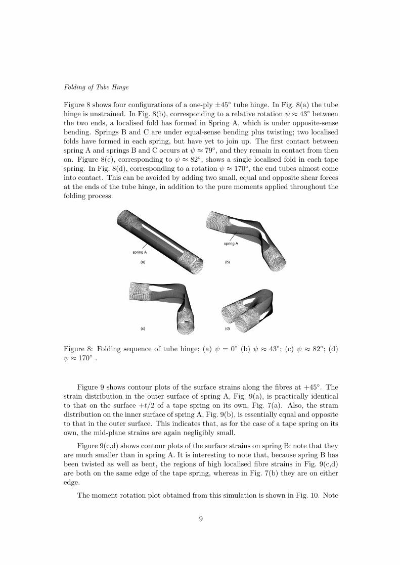
Figure 8 shows four configurations of a one-ply ±45◦ tube hinge. In Fig. 8(a) the tubehinge is unstrained. In Fig. 8(b), corresponding to a relative rotation ψ ≈ 43◦ betweenthe two ends, a localised fold has formed in Spring A, which is under opposite-sensebending. Springs B and C are under equal-sense bending plus twisting; two localisedfolds have formed in each spring, but have yet to join up. The first contact betweenspring A and springs B and C occurs at ψ ≈ 79◦, and they remain in contact from thenon. Figure 8(c), corresponding to ψ ≈ 82◦, shows a single localised fold in each tapespring. In Fig. 8(d), corresponding to a rotation ψ ≈ 170◦, the end tubes almost comeinto contact. This can be avoided by adding two small, equal and opposite shear forcesat the ends of the tube hinge, in addition to the pure moments applied throughout thefolding process.
spring A
(a) (b)
(c) (d)
spring A
Figure 8: Folding sequence of tube hinge; (a) ψ = 0◦ (b) ψ ≈ 43◦; (c) ψ ≈ 82◦; (d)ψ ≈ 170◦ .
Figure 9 shows contour plots of the surface strains along the fibres at +45◦. Thestrain distribution in the outer surface of spring A, Fig. 9(a), is practically identicalto that on the surface +t/2 of a tape spring on its own, Fig. 7(a). Also, the straindistribution on the inner surface of spring A, Fig. 9(b), is essentially equal and oppositeto that in the outer surface. This indicates that, as for the case of a tape spring on itsown, the mid-plane strains are again negligibly small.
Figure 9(c,d) shows contour plots of the surface strains on spring B; note that theyare much smaller than in spring A. It is interesting to note that, because spring B hasbeen twisted as well as bent, the regions of high localised fibre strains in Fig. 9(c,d)are both on the same edge of the tape spring, whereas in Fig. 7(b) they are on eitheredge.
The moment-rotation plot obtained from this simulation is shown in Fig. 10. Note
9
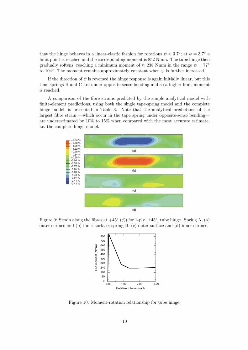
that the hinge behaves in a linear-elastic fashion for rotations ψ < 3.7◦; at ψ = 3.7◦ alimit point is reached and the corresponding moment is 852 Nmm. The tube hinge thengradually softens, reaching a minimum moment of ≈ 238 Nmm in the range ψ = 77◦
to 104◦. The moment remains approximately constant when ψ is further increased.
If the direction of ψ is reversed the hinge response is again initially linear, but thistime springs B and C are under opposite-sense bending and so a higher limit momentis reached.
A comparison of the fibre strains predicted by the simple analytical model withfinite-element predictions, using both the single tape-spring model and the completehinge model, is presented in Table 3. Note that the analytical predictions of thelargest fibre strain —which occur in the tape spring under opposite-sense bending—are underestimated by 10% to 15% when compared with the most accurate estimate,i.e. the complete hinge model.
+0.30 %+0.64 %+0.98 %+1.32 %+1.66 %+2.00 %+2.34 %
-2.41 %-2.41 %-2.07 %-1.73 %-1.39 %-1.05 %-0.72 %-0.35 %-0.04 %
(a)
(b)
(c)
(d)
Figure 9: Strain along the fibres at +45◦ (%) for 1-ply [±45◦] tube hinge. Spring A, (a)outer surface and (b) inner surface; spring B, (c) outer surface and (d) inner surface.
Relative rotation (rad)
End
mom
ent (
Nm
m)
800
720
640
560
480
400
320
240
160
80
2.001.00 3.000.000
Figure 10: Moment-rotation relationship for tube hinge.
10
Table 3: Maximum strains along fibres in tube hinges
Laminate Spring Bending Mode Location Anal. FE tape spring FE tube hinge(%) (%) (%)
1-ply A Opposite sense Outer -2.08 -2.37 -2.41[±45◦] Inner 2.08 2.25 2.34
B, C Equal sense Outer 0.00 -1.26, 1.23 -1.20, 1.20Inner 0.00 1.02 -1.33 -1.27, 1.04
2-ply A Opposite sense Outer -3.62 -4.10 -3.72[±45◦]2 Inner 3.62 3.88 3.31
B, C Equal sense Outer 0.00 -2.06, 1.90 -1.58, 1.48Inner 0.00 -2.02, 1.68 -1.61, 1.48
Discussion and Conclusions
A detailed study of the deformation and strains induced by folding CFRP tape springsand tube hinges with a ±45◦ lay-up has been presented. This study has shown thatthe largest fibre strains in tape-springs under opposite-sense bending occur in the uni-formly curved fold region and can be predicted with good accuracy using the analyticalexpressions obtained by Yee and Pellegrino (2003a). The same approach also gives ac-curate predictions for the maximum principal strains in tape-springs under equal-sensebending, which also occur in the uniformly curved fold region, however in this casethe maximum fibre strains occur in small edge regions. For the two specific cases thathave been analysed in detail it has been found that the maximum fibre strains werearound 50% the maximum principal strain in the fold region.
A parametric study of the effects of varying the angle θ subtended by the cross-section has been conducted, showing that the longitudinal radius at the centre of afolded one-ply [±45◦] tape spring decreases by about 30% when θ is increased from70◦ to 130◦. It approaches a value close to the analytical estimate, both for opposite-sense and equal-sense bending. The two-ply [±45◦]2 tape spring also converges to theanalytically estimated r, but at an even larger subtended angle θ = 150◦. Clearly, theincreased bending stiffness of the thicker laminate requires a larger subtended anglefor the stretching-dominated behaviour to take over.
¿From a design viewpoint, the principal attraction of tape springs with larger θ’sis that the they snap firmly into the straight configuration —a very attractive featurein the design of self-latching deployable structures—. Also, their peak strains areinsensitive to the fold angle. However, tape springs with smaller θ’s will generally havesmaller strains for the same fold radius.
A complete tube hinge consisting of three tape springs has been investigated. Thisstudy has shown that contact between the tape springs occurs at fold angles of about80◦, but does not affect substantially the distribution and magnitude of the maximumfibre strains. A finite element analysis of a single tape spring provided, for both casesthat have been considered, conservative estimates of the peak strains. These estimates
11
were particularly accurate for the single-ply tube hinge.
Turning to the specific tube hinge designs that were considered in this paper, ithas been shown —in Table 3— that an 82 mm long tube hinge with cross-sectionalradius of 6.5 mm and 50 mm long tape springs would be subject to a maximum fibrestrain of −2.4% in the folded configuration, if it is made from a one-ply [±45], 0.27 mmthick 913C-814-40% prepreg. This strain is just within the limit of the material. Atube hinge made from a two-ply [±45]2 laminate, would be 0.47 mm thick and wouldbe subject to maximum strains well in excess of the material limit. For this laminateto survive the folding process, the cross-sectional radius, or at least the radius of thetape spring that goes into opposite-sense bending should be increased.
Acknowledgements
The authors are grateful to Dr M.F. Sutcliffe for help and advice. Mr G.C. Dandoand Dr A. Freeman, of QinetiQ Ltd., have provided sample tube hinges and haveoffered advice on many occasions. Mr J. Ellis, of Hexcel, Duxford, UK, has providedmaterials and manufacturing facilities. Financial support from Corpus Christi College,Cambridge and QinetiQ Ltd is gratefully acknowledged.
References
ABAQUS, Inc. (2001). ABAQUS Theory and Standard User’s Manual, Version 6.2,Pawtucket, RI, USA.
Avery, W.B. (1998) Visilam 4: A laminate analysis spreadsheet, Boeing Corporation,Seattle.
Calladine, C.R. (1988) Love Centenary Lecture: The theory of thin shell structures1888 - 1988.The Institution of Mechanical Engineers Proceedings, 202 (42):1-9.
Jones, R.M. (1999). Mechanics of Composite Materials, Second Edition. Taylor &Francis, Philadelphia.
Rimrott, F.P.J. (1965). Storable tubular extendible member: a unique machine ele-ment. Machine Design, 37, 156-163.
Rimrott, F.P.J. (1970). Querschnittsverformung bei Torsion offener Profile. ZAMM,50, 775-778.
Yee, J.C.H. and Pellegrino, S. (2003a) CFRP tube hinges for deployable structures.Submitted for publication.
Yee, J.C.H. and Pellegrino, S. (2003b) Folding of composite structures. Conference onDeformation and Fracture of Composites (FRC-7), Sheffield University, 22-24 April2003.
12


![EVALUATING MEASUREMENT UNCERTAINTY IN … nonlinear pressure-overclosure relationship [7]. ... contact position was determined from the center of contact pressure on the tibial insert](https://img.pdfslide.net/doc/110x75/5af765617f8b9a5f588b75ac/evaluating-measurement-uncertainty-in-nonlinear-pressure-overclosure-relationship.jpg)