Embed Size (px)
Citation preview
Köhler integrators embedded into illumination optics add functionality
O. Dross*a, R. Mohedanoa , M. Hernándeza , A. Cetkovicb, J. C. Miñanob,c, P. Benítezb,c a Light Prescriptions Innovators Europe, Cedint, Campus Montegancedo, 28223 Madrid, Spain
b Universidad Politécnica de Madrid, Cedint, Campus Montegancedo, 28223 Madrid, Spain c LPI, 2400 Lincoln Avenue, Altadena, CA 91001, USA
ABSTRACT
The Köhler illumination concept was originally invented to achieve uniform illumination in microscopy1. Köhler integrators can also be formed by arrays of lenticulations that can be any combination of reflective and/or refractive surfaces, organized in corresponding pairs. Arrays of integrating facets can be arranged not only on flat surfaces but on rotationally symmetric and even freeform surfaces6. Currently flat lenslet arrays are widely applied as homogenizing optics2 for lithography, machine vision illumination, and projection.
Adding Köhler facets onto already designed surfaces can improve the optical system performance, while respecting its original function. In general, the optics output can be made somewhat independent of the source characteristics, although at the expense of a slight ètendue dilution or efficiency losses.
This work revises the Köhler concept and its application to different kind of optics, ranging from photovoltaic concentrators to automotive LED headlights. In the former, irradiance peaks on the solar cell can be avoided, while preserving high aiming tolerance (acceptance) of the solar concentrator. In the latter, LEDs drawbacks like large source image sizes, source misalignments, ill defined source edges, and low source radiance can be compensated.
Keywords: Köhler Integration, Nonimaging Optics, Concentration Photovoltaics, Automotive Lighting, Solid State lighting, Mircolens Arrays.
1. INTRODUCTION
There are a few standard methods that are used to provide uniform illumination on a target, among them, the so called Abbe and Köhler illumination1. The Abbe illumination images the light source onto the target area, and therefore works well only if the source itself has uniform irradiance. In the Köhler illumination concept, each point at the target area is illuminated by large portions of the source, but typically just a fraction of the intensity distribution. As a consequence, the irradiance on the target (which is the integral over part of the irradiance of the source) can be sufficiently uniform provided that the intensity of the source does not vary dramatically. If a single element (mirror, lens) is used to collect the flux of the source, the intensity variations of the source limit the achievable uniformity. Small solid angles tend to receive more uniform irradiance from a source so that, instead of a single pair of lenses focusing of each other, arrays of microlenses can be employed. Such Köhler lenslet arrays can provide high uniformity and efficiency at the same time.
Other integrating optics consist of hollow or dielectric light guides and mixing chambers. Multiple diffuse or specular reflections can provide very high uniformity but often at the expense of compactness and efficiency.
In this article we will concentrate on lenticular integrators consisting of two arrays of refractive or reflective facets. As shown below, integration can be applied for light homogenization but also to create special features such as sharp cutoffs or gradients in the output pattern (without the need of masks) and also for color mixing.
* [email protected]; phone + 49 211 29942074; lpi-llc.com
2. INTEGRATING ARCHITECTURES
2.1 Integration in one direction
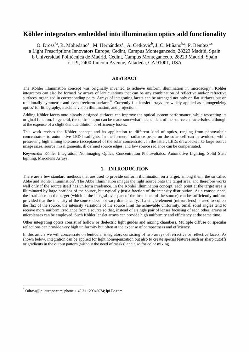
Köhler integration can be achieved by a single solid lens or by a pair of lens arrays to render an arbitrary intensity distribution of collimated light into a pill box intensity distribution. Figure 1 shows two symmetrical lenslet arrays separated by a dielectric material (refractive index n>1) by a distance t that is equal to their focal length. If no aberrations are present, all light hitting one lenslet array with an arbitrary intensity distribution within off axis angles limited by ±α would be transformed into constant intensity between ±α after the second lenslet, as long as the irradiance of the incoming light is constant over each lenslet. This condition can be met by choosing the lenslets sufficiently small.
Figure 1: Operation principles of a basic integrator lens array for perpendicular (left), max angle α incidence (center) and
illumination outside the integration zone (right)
If such an array is used between a condenser and a collimating lens, the integrator defines an “integration zone” d that is determined by:
)tan(2 αfd =
where f is the focal length of the collimating lens (see Figure 2). Light coming from each point inside the integrating zone illuminates the entire receiver.
Figure 2: A source, with an arbitrary irradiance distribution (gray shape, left) is transferred into a uniform irradiance distribution on the receiver by a symmetrical microlens array. If the rays were to be reversed, the constant irradiance on the right would have to emit discontinuously in angular space to each of the facets to reproduce the original source irradiance.
The output intensify of the integrator, or the irradiance if a collimation system is used downstream, does not depend on the source irradiance distribution within d so that any “structure” of the source is lost. If the integration zone is larger than the source, the source can be moved within the integration zone without affecting system performance.
The angular acceptance of integrators is limited by the image formation capabilities of the lenslets. For low f numbers, the focusing of the edge of the source onto the edge of the respective lenslet deteriorates, so that the resulting integrated pattern becomes fuzzier, less uniform, and less efficient.
2.2 Ètendue conservation
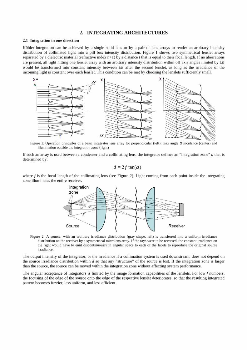
Although, rigorously speaking the ètendue is preserved, the “effective” ètendue can be increased by means of integrators, if, for instance, the resulting intensity distribution of an integrator is wider than the incoming beam. As denoted in Figure 3 for an integrator of 6 lenslets in 2 dimensions, the effective phase-space area or ètendue for the outgoing beam, indicated by the 6 grey lines, is much larger than the ètendue of collimated incoming light, because for all practical means the different ray bundles that exit after integration are now spread out of over a large phase space region.
Figure 3: Left: Phase space before and after integrator for perpendicular illumination as in Fig 1, left. Right: Phase space for angled illumination, see Fig 1, right
In practice, one chooses a fraction of the source ètendue that is to be captured by the design. If efficiency is most important, one intends to capture most of the source ètendue. If intensity or irradiance must be maximized, one chooses a smaller fraction of the ètendue where the source radiance is the highest. In most cases adding integrators will increase this chosen fractional ètendue because of the imperfections (i.e. aberrations) of the integrator and the fact that in three dimensions the source images generated by the first lenticular array can have strongly varying shapes, depending on the collimation scheme used (see below). In solar concentration the increase of ètendue does not result in lower concentration or efficiency but in a small reduction of acceptance angle (see Section 3).
2.3 Radial Integration
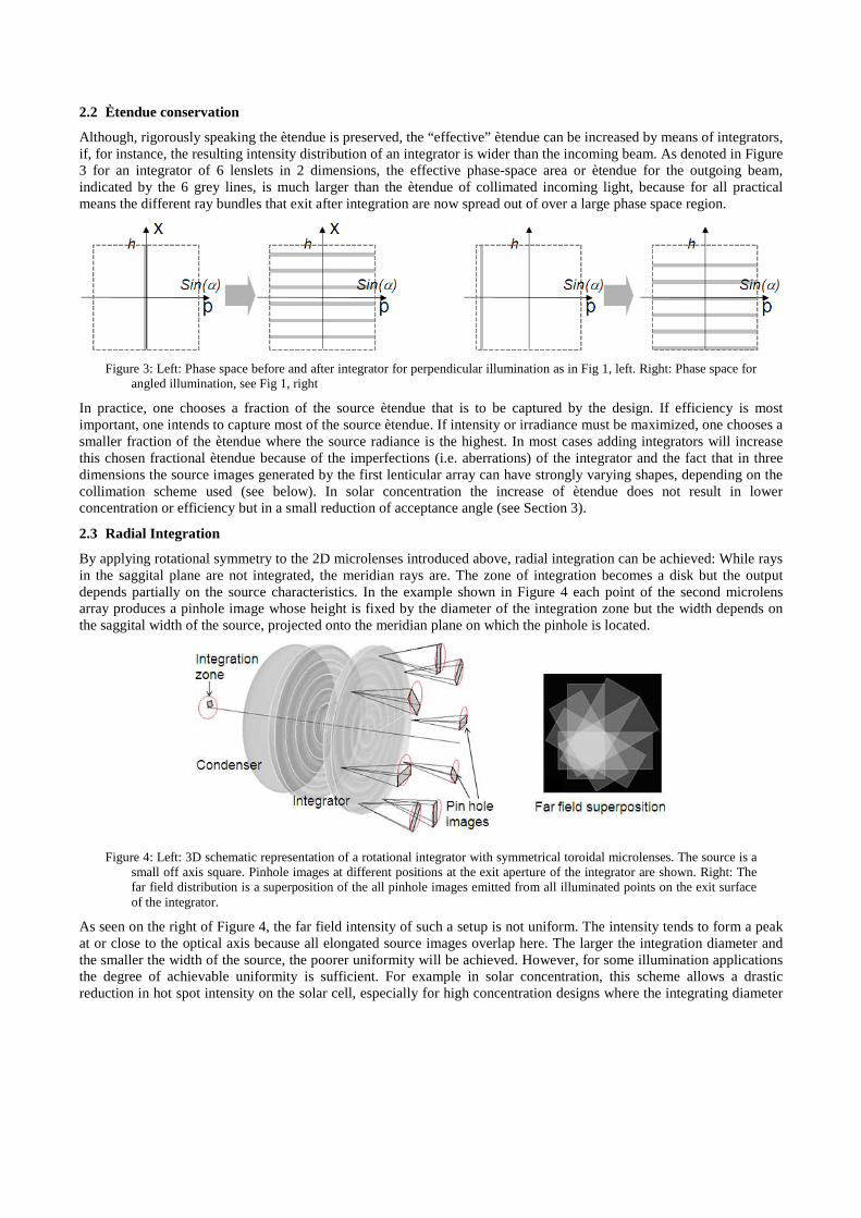
By applying rotational symmetry to the 2D microlenses introduced above, radial integration can be achieved: While rays in the saggital plane are not integrated, the meridian rays are. The zone of integration becomes a disk but the output depends partially on the source characteristics. In the example shown in Figure 4 each point of the second microlens array produces a pinhole image whose height is fixed by the diameter of the integration zone but the width depends on the saggital width of the source, projected onto the meridian plane on which the pinhole is located.
Figure 4: Left: 3D schematic representation of a rotational integrator with symmetrical toroidal microlenses. The source is a small off axis square. Pinhole images at different positions at the exit aperture of the integrator are shown. Right: The far field distribution is a superposition of the all pinhole images emitted from all illuminated points on the exit surface of the integrator.
As seen on the right of Figure 4, the far field intensity of such a setup is not uniform. The intensity tends to form a peak at or close to the optical axis because all elongated source images overlap here. The larger the integration diameter and the smaller the width of the source, the poorer uniformity will be achieved. However, for some illumination applications the degree of achievable uniformity is sufficient. For example in solar concentration, this scheme allows a drastic reduction in hot spot intensity on the solar cell, especially for high concentration designs where the integrating diameter
would be chosen to be similar to the acceptance angle (see Section 3). Complete uniformity is not needed here so that the simplicity of such a design makes is beneficial.
2.4 Planar Microlens arrays
Planar microlens arrays are well known and have been used for decades in microscopy illumination, laser beam shaping (flat top beams), different types of projection, and many other fields. Such systems can be easily designed by using (mostly square) arrays of rotationally symmetric microlenses with profiles defined as described in section 2.1 which now provided integration in two perpendicular directions. Such integrators work well if the incoming collimated light has constant angular spread. However, in many applications the angular cones at the receiving side of the first micro display have very different angular spreads (Figure 5).
Figure 5: Left: Arc lamp with a parabolic reflector, a pair of 2D microlens arrays and a collimation lens to illuminate a micro display for projection. Center: Graph of source images created on the surface of the second lenslet array through the first lenslet array. See reference 4. Right: Photo of glass microlens array with adjusted lenslet sizes to accommodate different source sizes.
A parabolic mirror produces much smaller angular spread close to its edge than the mirror center. Accordingly, the source images formed by a first (regular) microlens array at the second array have different orientations and sizes. The integrator can be designed to have such a large angular integration zone to include all source images, so that the secondary lens sizes are large enough to accept the full source images, but this leads to a considerable ètendue dilution (some of the integrator facets will not be fully flashed). By adjusting the sizes of the individual microlenses of the 2nd array a design with much lower ètendue can be achieved.
2.5 Integration superimposed on aspheric profiles
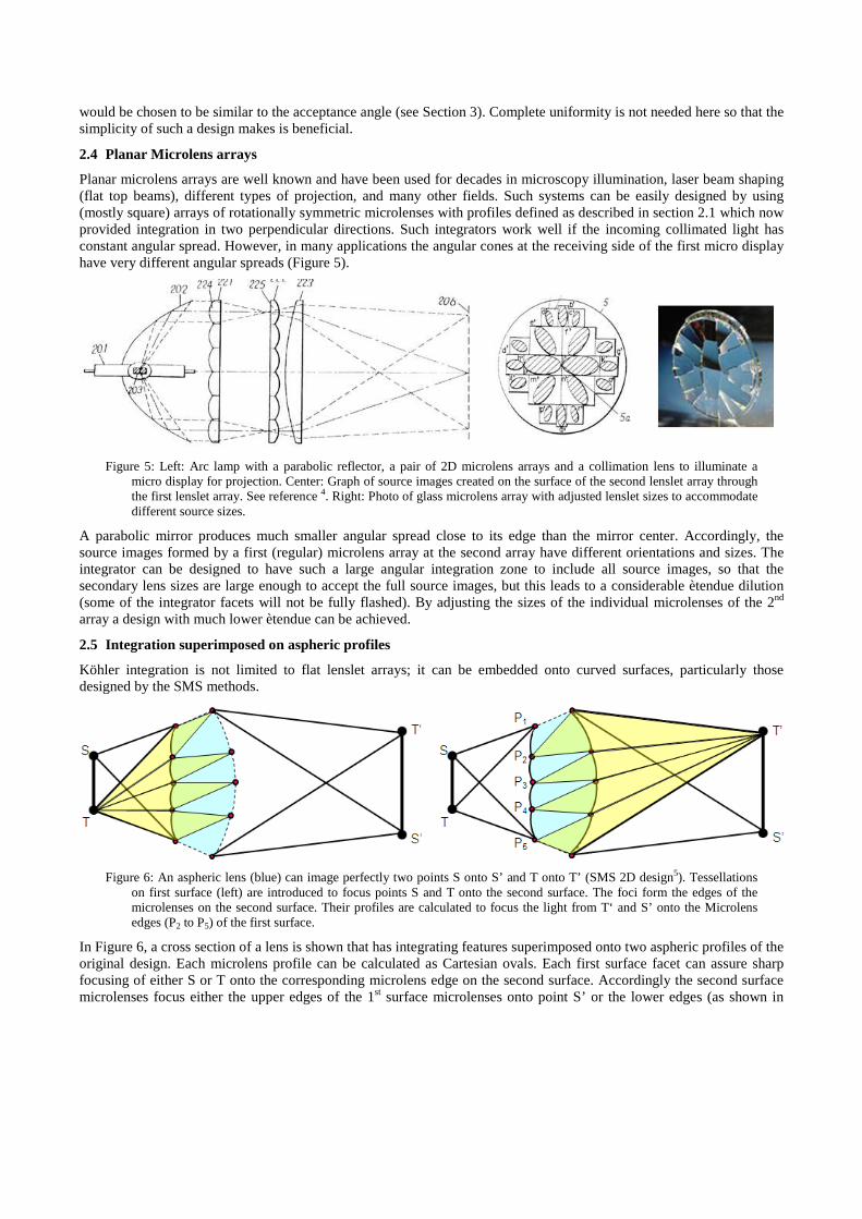
Köhler integration is not limited to flat lenslet arrays; it can be embedded onto curved surfaces, particularly those designed by the SMS methods.
Figure 6: An aspheric lens (blue) can image perfectly two points S onto S’ and T onto T’ (SMS 2D design5). Tessellations on first surface (left) are introduced to focus points S and T onto the second surface. The foci form the edges of the microlenses on the second surface. Their profiles are calculated to focus the light from T‘ and S’ onto the Microlens edges (P2 to P5) of the first surface.
In Figure 6, a cross section of a lens is shown that has integrating features superimposed onto two aspheric profiles of the original design. Each microlens profile can be calculated as Cartesian ovals. Each first surface facet can assure sharp focusing of either S or T onto the corresponding microlens edge on the second surface. Accordingly the second surface microlenses focus either the upper edges of the 1st surface microlenses onto point S’ or the lower edges (as shown in
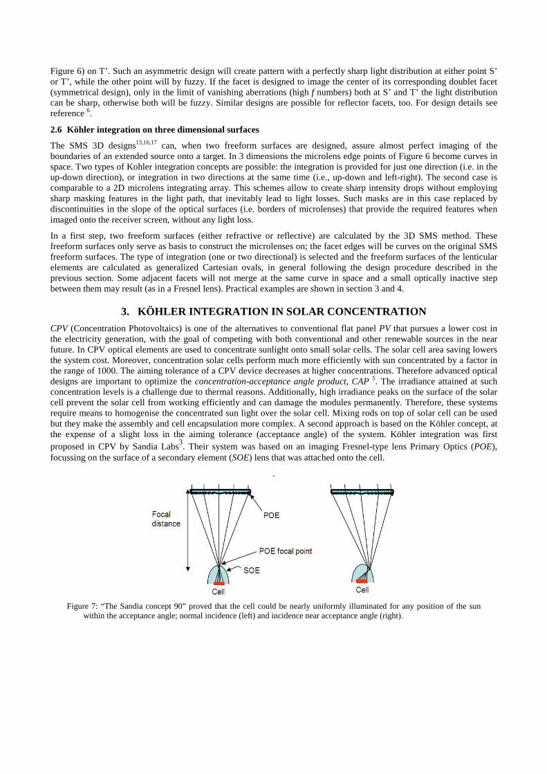
Figure 6) on T’. Such an asymmetric design will create pattern with a perfectly sharp light distribution at either point S’ or T’, while the other point will by fuzzy. If the facet is designed to image the center of its corresponding doublet facet (symmetrical design), only in the limit of vanishing aberrations (high f numbers) both at S’ and T’ the light distribution can be sharp, otherwise both will be fuzzy. Similar designs are possible for reflector facets, too. For design details see reference 6.
2.6 Köhler integration on three dimensional surfaces
The SMS 3D designs13,16,17 can, when two freeform surfaces are designed, assure almost perfect imaging of the boundaries of an extended source onto a target. In 3 dimensions the microlens edge points of Figure 6 become curves in space. Two types of Kohler integration concepts are possible: the integration is provided for just one direction (i.e. in the up-down direction), or integration in two directions at the same time (i.e., up-down and left-right). The second case is comparable to a 2D microlens integrating array. This schemes allow to create sharp intensity drops without employing sharp masking features in the light path, that inevitably lead to light losses. Such masks are in this case replaced by discontinuities in the slope of the optical surfaces (i.e. borders of microlenses) that provide the required features when imaged onto the receiver screen, without any light loss.
In a first step, two freeform surfaces (either refractive or reflective) are calculated by the 3D SMS method. These freeform surfaces only serve as basis to construct the microlenses on; the facet edges will be curves on the original SMS freeform surfaces. The type of integration (one or two directional) is selected and the freeform surfaces of the lenticular elements are calculated as generalized Cartesian ovals, in general following the design procedure described in the previous section. Some adjacent facets will not merge at the same curve in space and a small optically inactive step between them may result (as in a Fresnel lens). Practical examples are shown in section 3 and 4.
3. KÖHLER INTEGRATION IN SOLAR CONCENTRATION
CPV (Concentration Photovoltaics) is one of the alternatives to conventional flat panel PV that pursues a lower cost in the electricity generation, with the goal of competing with both conventional and other renewable sources in the near future. In CPV optical elements are used to concentrate sunlight onto small solar cells. The solar cell area saving lowers the system cost. Moreover, concentration solar cells perform much more efficiently with sun concentrated by a factor in the range of 1000. The aiming tolerance of a CPV device decreases at higher concentrations. Therefore advanced optical designs are important to optimize the concentration-acceptance angle product, CAP 5. The irradiance attained at such concentration levels is a challenge due to thermal reasons. Additionally, high irradiance peaks on the surface of the solar cell prevent the solar cell from working efficiently and can damage the modules permanently. Therefore, these systems require means to homogenise the concentrated sun light over the solar cell. Mixing rods on top of solar cell can be used but they make the assembly and cell encapsulation more complex. A second approach is based on the Köhler concept, at the expense of a slight loss in the aiming tolerance (acceptance angle) of the system. Köhler integration was first proposed in CPV by Sandia Labs3. Their system was based on an imaging Fresnel-type lens Primary Optics (POE), focussing on the surface of a secondary element (SOE) lens that was attached onto the cell.
.
Figure 7: “The Sandia concept 90” proved that the cell could be nearly uniformly illuminated for any position of the sun
within the acceptance angle; normal incidence (left) and incidence near acceptance angle (right).
In this scheme, the SOE images the primary entry aperture (which is uniformly illuminated) on the cell, which therefore will be uniformly illuminated as well. At the same time, the primary images the sun on the SOE surface, thus the sun spot slides throughout the secondary surface when the device points slightly away from the sun. However, this concept is limited to medium concentration levels
For a given concentration level, the maximum acceptance angle is achieved when the optic illuminates the cell isotropically5 and the latter is embedded in a medium that is optically dense (n>1). A high concentration PV system must maintain high acceptance angles to ensure efficient operation in spite of inevitable sun tracking errors. Some concentrators in which Köhler facets have been superimposed onto the nonimaging architectures have been presented elsewhere7,8,9.
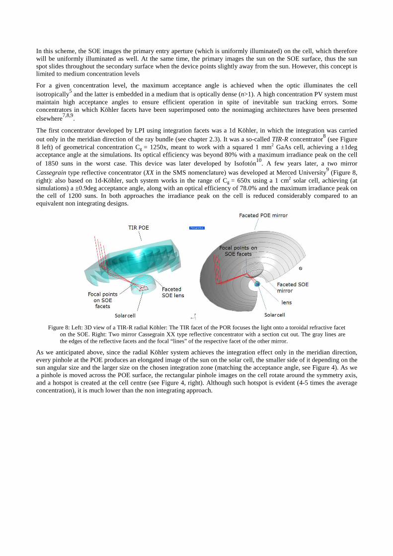
The first concentrator developed by LPI using integration facets was a 1d Köhler, in which the integration was carried out only in the meridian direction of the ray bundle (see chapter 2.3). It was a so-called TIR-R concentrator8 (see Figure 8 left) of geometrical concentration Cg = 1250x, meant to work with a squared 1 mm2 GaAs cell, achieving a ±1deg acceptance angle at the simulations. Its optical efficiency was beyond 80% with a maximum irradiance peak on the cell of 1850 suns in the worst case. This device was later developed by Isofotón10. A few years later, a two mirror Cassegrain type reflective concentrator (XX in the SMS nomenclature) was developed at Merced University9 (Figure 8, right): also based on 1d-Köhler, such system works in the range of Cg = 650x using a 1 cm2 solar cell, achieving (at simulations) a ±0.9deg acceptance angle, along with an optical efficiency of 78.0% and the maximum irradiance peak on the cell of 1200 suns. In both approaches the irradiance peak on the cell is reduced considerably compared to an equivalent non integrating designs.
Figure 8: Left: 3D view of a TIR-R radial Köhler: The TIR facet of the POR focuses the light onto a toroidal refractive facet on the SOE. Right: Two mirror Cassegrain XX type reflective concentrator with a section cut out. The gray lines are the edges of the reflective facets and the focal “lines” of the respective facet of the other mirror.
As we anticipated above, since the radial Köhler system achieves the integration effect only in the meridian direction, every pinhole at the POE produces an elongated image of the sun on the solar cell, the smaller side of it depending on the sun angular size and the larger size on the chosen integration zone (matching the acceptance angle, see Figure 4). As we a pinhole is moved across the POE surface, the rectangular pinhole images on the cell rotate around the symmetry axis, and a hotspot is created at the cell centre (see Figure 4, right). Although such hotspot is evident (4-5 times the average concentration), it is much lower than the non integrating approach.
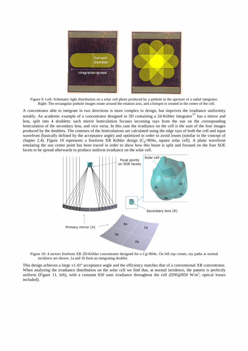
Figure 9: Left: Schematic light distribution on a solar cell photo produced by a pinhole in the aperture of a radial integrator. Right: The rectangular pinhole images rotate around the rotation axis, and a hotspot is created in the centre of the cell.
A concentrator able to integrate in two directions is more complex to design, but improves the irradiance uniformity notably. An academic example of a concentrator designed in 3D containing a 2d-Köhler integrator11 has a mirror and lens, split into 4 doublets: each mirror lenticulation focuses incoming rays from the sun on the corresponding lenticulation of the secondary lens, and vice versa. In this case the irradiance on the cell is the sum of the four images produced by the doublets. The contours of the lenticulations are calculated using the edge rays of both the cell and input wavefront (basically defined by the acceptance angle) and optimized in order to avoid losses (similar to the concept of chapter 2.4). Figure 10 represents a freeform XR Köhler design (Cg=804x, square solar cell). A plane wavefront emulating the sun centre point has been traced in order to show how this beam is split and focused on the four SOE facets to be spread afterwards to produce uniform irradiance on the solar cell.
Solar cell
1a
1b
3a
2a
2b
3b
Secondary lens (R)
Primary mirror (X)4a
4b
Focal points
on SOE facets
Figure 10: 4 sectors freeform XR 2D-Köhler concentrator designed for a Cg=804x. On left top corner, ray paths at normal incidence are shown. 1a and 1b form an integrating doublet.
This design achieves a large ±1.41º acceptance angle and the efficiency matches that of a conventional XR concentrator. When analysing the irradiance distribution on the solar cell we find that, at normal incidence, the pattern is perfectly uniform (Figure 11, left), with a constant 650 suns irradiance throughout the cell (DNI@850 W/m2, optical losses included).
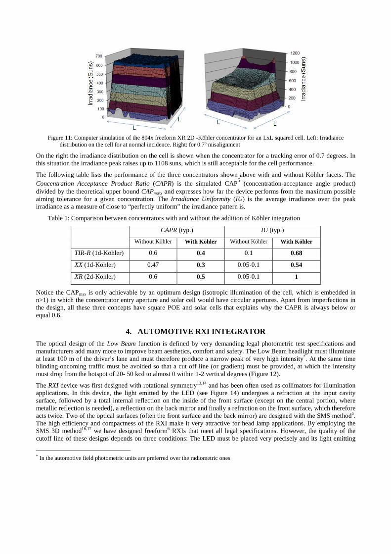
Figure 11: Computer simulation of the 804x freeform XR 2D -Köhler concentrator for an LxL squared cell. Left: Irradiance distribution on the cell for at normal incidence. Right: for 0.7º misalignment
On the right the irradiance distribution on the cell is shown when the concentrator for a tracking error of 0.7 degrees. In this situation the irradiance peak raises up to 1108 suns, which is still acceptable for the cell performance.
The following table lists the performance of the three concentrators shown above with and without Köhler facets. The Concentration Acceptance Product Ratio (CAPR) is the simulated CAP5 (concentration-acceptance angle product) divided by the theoretical upper bound CAPmax, and expresses how far the device performs from the maximum possible aiming tolerance for a given concentration. The Irradiance Uniformity (IU) is the average irradiance over the peak irradiance as a measure of close to “perfectly uniform” the irradiance pattern is.
Table 1: Comparison between concentrators with and without the addition of Köhler integration
CAPR (typ.) IU (typ.)
Without Köhler With Köhler Without Köhler With Köhler
TIR-R (1d-Köhler) 0.6 0.4 0.1 0.68
XX (1d-Köhler) 0.47 0.3 0.05-0.1 0.54
XR (2d-Köhler) 0.6 0.5 0.05-0.1 1
Notice the CAPmax is only achievable by an optimum design (isotropic illumination of the cell, which is embedded in n>1) in which the concentrator entry aperture and solar cell would have circular apertures. Apart from imperfections in the design, all these three concepts have square POE and solar cells that explains why the CAPR is always below or equal 0.6.
4. AUTOMOTIVE RXI INTEGRATOR
The optical design of the Low Beam function is defined by very demanding legal photometric test specifications and manufacturers add many more to improve beam aesthetics, comfort and safety. The Low Beam headlight must illuminate at least 100 m of the driver’s lane and must therefore produce a narrow peak of very high intensity*. At the same time blinding oncoming traffic must be avoided so that a cut off line (or gradient) must be provided, at which the intensity must drop from the hotspot of 20- 50 kcd to almost 0 within 1-2 vertical degrees (Figure 12).
The RXI device was first designed with rotational symmetry13,14 and has been often used as collimators for illumination applications. In this device, the light emitted by the LED (see Figure 14) undergoes a refraction at the input cavity surface, followed by a total internal reflection on the inside of the front surface (except on the central portion, where metallic reflection is needed), a reflection on the back mirror and finally a refraction on the front surface, which therefore acts twice. Two of the optical surfaces (often the front surface and the back mirror) are designed with the SMS method5. The high efficiency and compactness of the RXI make it very attractive for head lamp applications. By employing the SMS 3D method16,17 we have designed freeform6 RXIs that meet all legal specifications. However, the quality of the cutoff line of these designs depends on three conditions: The LED must be placed very precisely and its light emitting
* In the automotive field photometric units are preferred over the radiometric ones
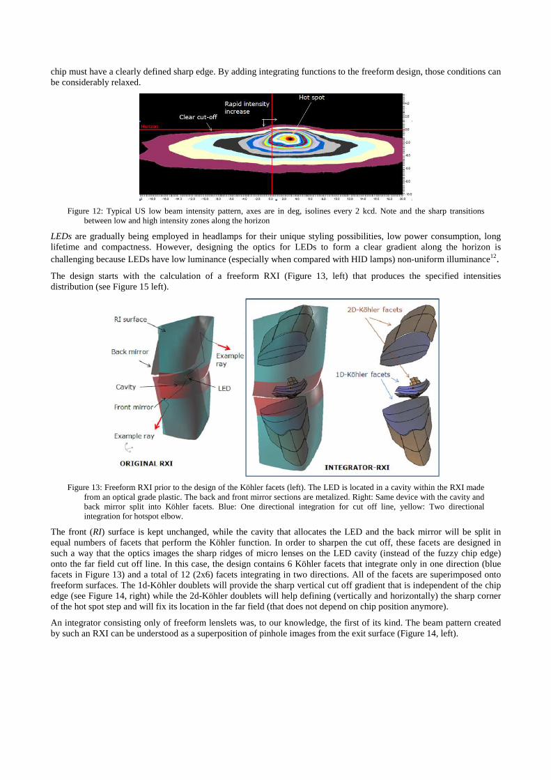
chip must have a clearly defined sharp edge. By adding integrating functions to the freeform design, those conditions can be considerably relaxed.
Figure 12: Typical US low beam intensity pattern, axes are in deg, isolines every 2 kcd. Note and the sharp transitions
between low and high intensity zones along the horizon
LEDs are gradually being employed in headlamps for their unique styling possibilities, low power consumption, long lifetime and compactness. However, designing the optics for LEDs to form a clear gradient along the horizon is challenging because LEDs have low luminance (especially when compared with HID lamps) non-uniform illuminance12.
The design starts with the calculation of a freeform RXI (Figure 13, left) that produces the specified intensities distribution (see Figure 15 left).
Figure 13: Freeform RXI prior to the design of the Köhler facets (left). The LED is located in a cavity within the RXI made from an optical grade plastic. The back and front mirror sections are metalized. Right: Same device with the cavity and back mirror split into Köhler facets. Blue: One directional integration for cut off line, yellow: Two directional integration for hotspot elbow.
The front (RI) surface is kept unchanged, while the cavity that allocates the LED and the back mirror will be split in equal numbers of facets that perform the Köhler function. In order to sharpen the cut off, these facets are designed in such a way that the optics images the sharp ridges of micro lenses on the LED cavity (instead of the fuzzy chip edge) onto the far field cut off line. In this case, the design contains 6 Köhler facets that integrate only in one direction (blue facets in Figure 13) and a total of 12 (2x6) facets integrating in two directions. All of the facets are superimposed onto freeform surfaces. The 1d-Köhler doublets will provide the sharp vertical cut off gradient that is independent of the chip edge (see Figure 14, right) while the 2d-Köhler doublets will help defining (vertically and horizontally) the sharp corner of the hot spot step and will fix its location in the far field (that does not depend on chip position anymore).
An integrator consisting only of freeform lenslets was, to our knowledge, the first of its kind. The beam pattern created by such an RXI can be understood as a superposition of pinhole images from the exit surface (Figure 14, left).
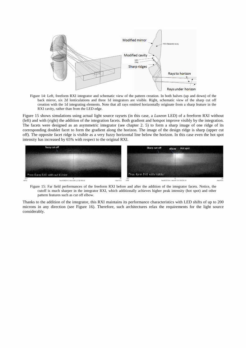
Figure 14: Left, freeform RXI integrator and schematic view of the pattern creation. In both halves (up and down) of the
back mirror, six 2d lenticulations and three 1d integrators are visible. Right, schematic view of the sharp cut off creation with the 1d integrating elements. Note that all rays emitted horizontally originate from a sharp feature in the RXI cavity, rather than from the LED edge.
Figure 15 shows simulations using actual light source raysets (in this case, a Luxeon LED) of a freeform RXI without (left) and with (right) the addition of the integration facets. Both gradient and hotspot improve visibly by the integration. The facets were designed as an asymmetric integrator (see chapter 2. 5) to form a sharp image of one ridge of its corresponding doublet facet to form the gradient along the horizon. The image of the design ridge is sharp (upper cut off). The opposite facet ridge is visible as a very fuzzy horizontal line below the horizon. In this case even the hot spot intensity has increased by 65% with respect to the original RXI.
Figure 15: Far field performances of the freeform RXI before and after the addition of the integrator facets. Notice, the cutoff is much sharper in the integrator RXI, which additionally achieves higher peak intensity (hot spot) and other pattern features such as cut off elbow.
Thanks to the addition of the integrator, this RXI maintains its performance characteristics with LED shifts of up to 200 microns in any direction (see Figure 16). Therefore, such architectures relax the requirements for the light source considerably.
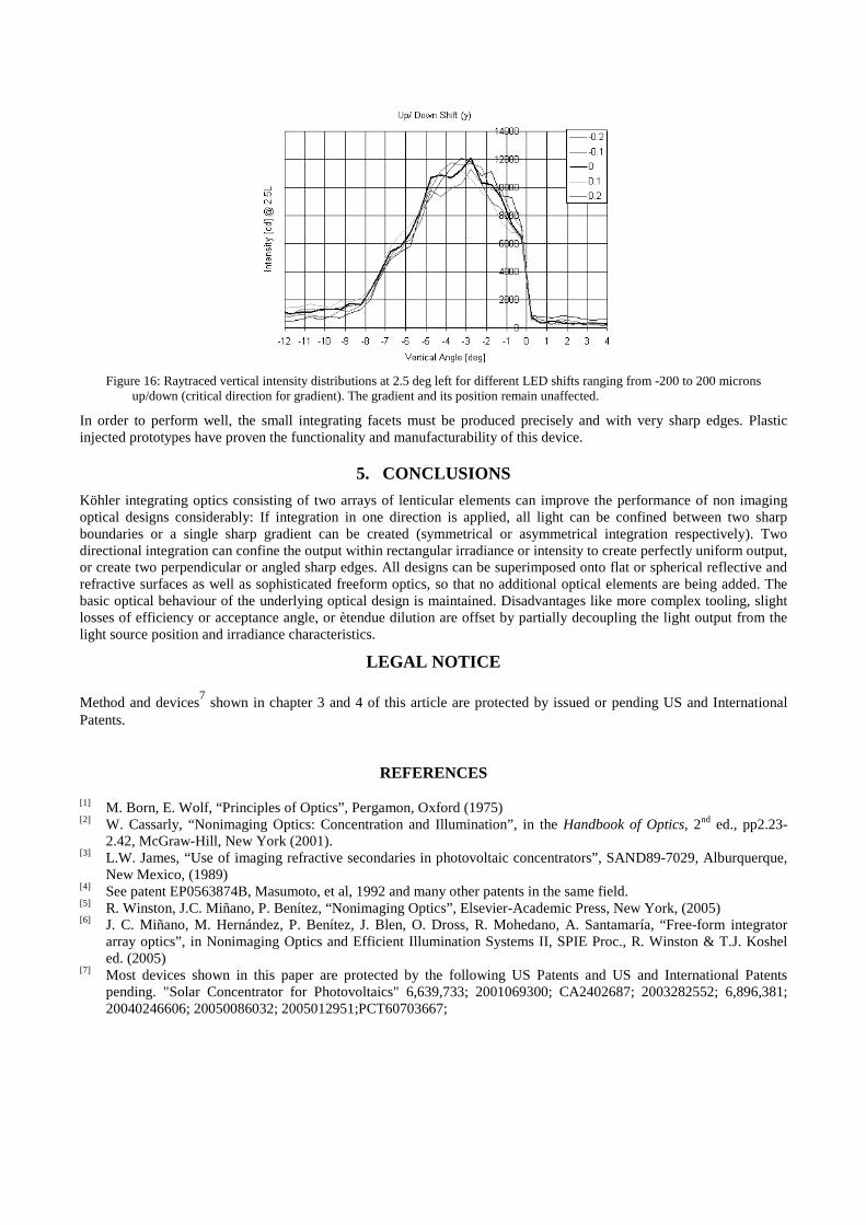
Figure 16: Raytraced vertical intensity distributions at 2.5 deg left for different LED shifts ranging from -200 to 200 microns up/down (critical direction for gradient). The gradient and its position remain unaffected.
In order to perform well, the small integrating facets must be produced precisely and with very sharp edges. Plastic injected prototypes have proven the functionality and manufacturability of this device.
5. CONCLUSIONS
Köhler integrating optics consisting of two arrays of lenticular elements can improve the performance of non imaging optical designs considerably: If integration in one direction is applied, all light can be confined between two sharp boundaries or a single sharp gradient can be created (symmetrical or asymmetrical integration respectively). Two directional integration can confine the output within rectangular irradiance or intensity to create perfectly uniform output, or create two perpendicular or angled sharp edges. All designs can be superimposed onto flat or spherical reflective and refractive surfaces as well as sophisticated freeform optics, so that no additional optical elements are being added. The basic optical behaviour of the underlying optical design is maintained. Disadvantages like more complex tooling, slight losses of efficiency or acceptance angle, or ètendue dilution are offset by partially decoupling the light output from the light source position and irradiance characteristics.
LEGAL NOTICE Method and devices7 shown in chapter 3 and 4 of this article are protected by issued or pending US and International Patents.
REFERENCES
[1] M. Born, E. Wolf, “Principles of Optics”, Pergamon, Oxford (1975) [2] W. Cassarly, “Nonimaging Optics: Concentration and Illumination”, in the Handbook of Optics, 2nd ed., pp2.23-
2.42, McGraw-Hill, New York (2001). [3] L.W. James, “Use of imaging refractive secondaries in photovoltaic concentrators”, SAND89-7029, Alburquerque,
New Mexico, (1989) [4] See patent EP0563874B, Masumoto, et al, 1992 and many other patents in the same field. [5] R. Winston, J.C. Miñano, P. Benítez, “Nonimaging Optics”, Elsevier-Academic Press, New York, (2005) [6] J. C. Miñano, M. Hernández, P. Benítez, J. Blen, O. Dross, R. Mohedano, A. Santamaría, “Free-form integrator
array optics”, in Nonimaging Optics and Efficient Illumination Systems II, SPIE Proc., R. Winston & T.J. Koshel ed. (2005)
[7] Most devices shown in this paper are protected by the following US Patents and US and International Patents pending. "Solar Concentrator for Photovoltaics" 6,639,733; 2001069300; CA2402687; 2003282552; 6,896,381; 20040246606; 20050086032; 2005012951;PCT60703667;

[8] Hernandez, M. Benitez, P. Minano, J.C. Alvarez, J.L. Diaz, V. Alonso, J., “Sunlight spectrum on cell through very high concentration optics”, 3th World Conference on Photovoltaic Energy Conversion, Osaka, (2003). Volume: 1, On page(s): 889- 891
[9] P. Benitez, A. Cvetkovic, R. Winston, G. Díaz, L. Reed, J. Cisneros, A. Tovar, A. Ritschel, J. Wright, “High-Concentration Mirror-Based Köhler Integrating System for Tandem Solar Cells”, 4th World Conference on Photovoltaic Energy Conversion, Hawaii, (2006)
[10] http://www.isofoton.com/technicalhtml/secciones/desarrollos/sistemas.asp [11] M. Hernández, A. Cvetkovic, P. Benítez, J. C. Miñano, “High-performance Köhler concentrators with uniform
irradiance on solar cell” in Nonimaging Optics and Efficient Illumination Systems II, SPIE Proc., R. Winston & T.J. Koshel ed (2008)
[12] Oliver Dross, Aleksandra Cvetkovic, Pablo Benítez, Juan C. Miñano, Julio Chaves. “Novel LED Headlamp architectures that create high quality patterns independent of LED shortcomings”, Proeceedings ISAL, (2005)
[13] J.C. Miñano, J.C. González, P. Benítez, “RXI: A high-gain, compact, nonimaging concentrator”. Appl. Opt., 34, 34 (1995), pp. 7850-7856.
[14] U.S. Patent 6,639,733. "High Efficiency Non-Imaging Optics". [15] R. Winston, J.C. Miñano, P. Benítez, “Nonimaging Optics”, Elsevier-Academic Press, New York, (2005) [16] P. Benítez , J.C. Miñano, J. Blen, R. Mohedano, J. Chaves, O. Dross, M. Hernández, J.L. Alvarez, W. Falicof.,
“Simultaneous multiple surface optical design method in three dimensions”, Opt. Eng, 43(7) 1489-1502, (2004). [17] Patent Pablo Benítez, Juan C. Miñano, Rubén Mohedano, Jose Blen, Julio Chaves, Maikel Hernández, “Three-
Dimensional Simultaneous Multiple-Surface Method and Free-form Illumination-Optics Designed Therefrom”, U.S. Utility Application 10/901,919
[18] O. Dross, R. Mohedano, P. Benítez, J.C. Miñano, J. Chaves, J. Blen, M. Hernández, F. Muñoz “Review of SMS Design Methods and Real World Applications”, in Nonimaging Optics and Efficient Illumination Systems, SPIE Proc., R. Winston & T.J. Koshel ed., pp.35-47, (2004).


![GT48 Integrators Manual_P1C[1]](https://img.pdfslide.net/doc/110x75/577d358c1a28ab3a6b90c114/gt48-integrators-manualp1c1.jpg)