Embed Size (px)
Citation preview
Kia, THE COMPANYThank you for becoming the owner of a new Kia vehicle.As a global car manufacturer focused on building high-quality vehi-cles with exceptional value, Kia Motors is dedicated to providing youwith a customer service experience that exceeds your expectations.
All information contained in this Owner’s Manual is accurate at thetime of publication. However, Kia reserves the right to make changesat any time so that our policy of continual product improvement canbe carried out.
This manual applies to all models of this vehicle and includes descrip-tions and explanations of optional as well as standard equipment. As aresult, you may encounter material in this manual that is not applica-ble to your specific Kia vehicle.
Drive safely and enjoy your Kia!
i
Thank you for choosing a Kia vehicle.When you require service, remember that your Kia dealerknows your vehicle best. Your dealer has factory-trained tech-nicians, recommended special tools and genuine Kia replace-ment parts. It is dedicated to your complete customer satisfac-tion.Because subsequent owners require this important informationas well, this publication should remain with the vehicle if it issold.This manual will familiarize you with operational, mainte-nance and safety information about your new vehicle. It is sup-plemented by a Warranty and Consumer Information manualthat provides important information on all warranties regardingyour vehicle.We urge you to read these publications carefully and follow therecommendations to help assure enjoyable and safe operationof your new vehicle.Kia offers a great variety of options, components and featuresfor its various models. Therefore, some of the equipmentdescribed in this manual, along with the various illustrations,may not be applicable to your particular vehicle.
The information and specifications provided in this manualwere accurate at the time of printing. Kia reserves the right todiscontinue or change specifications or design at any timewithout notice and without incurring any obligation. If youhave questions, always check with your Kia dealer.We assure you of our continuing interest in your motoringpleasure and satisfaction in your Kia vehicle.
© 2013 Kia Canada Inc.All rights reserved. Reproduction by any means, electronic ormechanical, including photocopying, recording, or by anyinformation storage and retrieval system or translation inwhole or part is not permitted without written authorizationfrom Kia Canada Inc..Printed in Korea
Foreword
ii
1
2
3
4
5
6
7
8
I
IntroductionHow to use this manual / Fuel requirements / Vehicle break-in process
Your vehicle at a glanceExterior overview / Interior overview / Instrument panel overview / Engine compartment
Safety features of your vehicleSeats / Seat belts / Child restraint system / Air bag
Features of your vehicleKeys / Door locks / Trunk / Windows / Hood / Fuel filler lid / Panoramic sunroof / Steering wheel / Mirrors /Instrument cluster / Lighting / Wipers & Washers / Climate control system / Audio system / Etc.
Driving your vehicleBefore driving / Engine start/stop button / Transaxle / Brake system / Cruise control system / Smart cruise control system / Winter driving / Vehicle load limit / Etc.
What to do in an emergencyRoad warning / Emergency while driving / Emergency starting / Engine overheat / TPMS / Flat tire / Towing / Etc.
MaintenanceEngine compartment / Maintenance service / Engine oil / Engine coolant / Brake fluid / Washer fluid /Parking brake / Air cleaner / Wiper blades / Battery / Tire and wheels / Fuses / Etc.
Specifications & Consumer information
Index
table of contents
1
Introduction
How to use this manual . . . . . . . . . . . . . . . . . . . . . . 1-2Fuel requirements . . . . . . . . . . . . . . . . . . . . . . . . . . 1-3
• Gasoline containing alcohol and methanol . . . . . . . . . 1-3• Do not use methanol . . . . . . . . . . . . . . . . . . . . . . . . . . . 1-4• Fuel Additives . . . . . . . . . . . . . . . . . . . . . . . . . . . . . . . . 1-4
Vehicle Break-In Process . . . . . . . . . . . . . . . . . . . . . 1-5
Introduction
21
We want to help you get the greatestpossible driving pleasure from yourvehicle. Your Owner’s Manual canassist you in many ways. We strong-ly recommend that you read theentire manual. In order to minimizethe chance of death or injury, youmust read the WARNING and CAU-TION sections in the manual.Illustrations complement the wordsin this manual to best explain how toenjoy your vehicle. By reading yourmanual, you will learn about fea-tures, important safety information,and driving tips under various roadconditions.
The general layout of the manual isprovided in the Table of Contents.Use the index when looking for aspecific area or subject; it has analphabetical listing of all located inthe back of this manual.Sections: This manual has eight sec-tions plus an index. Each sectionbegins with a brief list of contents soyou can tell at a glance if that sectionhas the information you want.
You will find various types of safetyinstructions in this manual. Theseinstructions were prepared toenhance your personal safety.Carefully read and follow ALL proce-dures and recommendations provid-ed in these instructions.
✽✽ NOTICEA NOTICE indicates interesting orhelpful information is being provided.
HOW TO USE THIS MANUAL
WARNING A WARNING indicates a situationin which harm, serious bodilyinjury or death could result if thewarning is ignored.
CAUTIONA CAUTION indicates a situationin which damage to your vehiclecould result if the caution isignored.
1 3
Introduction
Your new Kia vehicle is designed touse only unleaded fuel having apump octane number ((R+M)/2) of87 (Research Octane Number 91) orhigher.
Your new vehicle is designed toobtain maximum performance withUNLEADED FUEL, as well as mini-mize exhaust emissions and sparkplug fouling.
Never add any fuel system cleaningagents to the fuel tank other thanwhat has been specified. (Consult anauthorized Kia dealer for details.)
✽✽ NOTICETighten the cap until it clicks onetime, otherwise the fuel cap openwarning indicator light (or LCDdisplay) will illuminate.
Gasoline containing alcohol andmethanolGasohol, a mixture of gasoline andethanol (also known as grain alco-hol), and gasoline or gasohol con-taining methanol (also known aswood alcohol) are being marketedalong with or instead of leaded orunleaded gasoline.Do not use gasohol containing morethan 10% ethanol, and do not usegasoline or gasohol containing anymethanol. Either of these fuels maycause drivability problems and dam-age to the fuel system.Discontinue using gasohol of anykind if drivability problems occur.Vehicle damage or drivability prob-lems may not be covered by themanufacturer’s warranty if they resultfrom the use of:1. Gasohol containing more than
10% ethanol.2. Gasoline or gasohol containing
methanol.3. Leaded fuel or leaded gasohol.
FUEL REQUIREMENTS
WARNING - Refueling• Do not "top off" after the noz-
zle automatically shuts off.Attempts to force more fuelinto the tank can cause fueloverflow onto you and theground causing a risk of fire.
• Always check that the fuel capis installed securely to pre-vent fuel spillage, especiallyin the event of an accident.
Introduction
41
"E85" fuel is an alternative fuel com-prised of 85 percent ethanol and 15percent gasoline, and is manufac-tured exclusively for use in FlexibleFuel Vehicles. “E85” is not compati-ble with your vehicle. Use of “E85”may result in poor engine perform-ance and damage to your vehicle'sengine and fuel system. Kia recom-mends that customers do not usefuel with an ethanol content exceed-ing 10 percent.
✽✽ NOTICEYour New Vehicle Limited Warrantydoes not cover damage to the fuelsystem or any performance prob-lems caused by the use of “E85” fuel.
Use of MTBEKia recommends avoiding fuels con-taining MTBE (Methyl Tertiary ButylEther) over 15.0% vol. (OxygenContent 2.7% weight) in your vehicle.Fuel containing MTBE over 15.0%vol. (Oxygen Content 2.7% weight)may reduce vehicle performance andproduce vapor lock or hard starting.
Do not use methanolFuels containing methanol (woodalcohol) should not be used in yourvehicle. This type of fuel can reducevehicle performance and damagecomponents of the fuel system.
Fuel AdditivesKia recommends that you use goodquality gasolines treated with deter-gent additives such as TOP TIERDetergent Gasoline, which helpsprevent deposit formation in theengine. These gasolines will help theengine run cleaner and enhance per-formance of the Emission ControlSystem. For more information onTOP TIER Detergent Gasoline,please go to the website (www.top-tiergas.com).For Customers who do not use TOPTIER Detergent Gasoline regularly,and have problems starting or theengine does not run smoothly, addi-tives that you can buy separatelymay be added to the gasoline. IfTOP TIER Detergent Gasoline is notavailable, one bottle of additiveadded to the fuel tank at 12,000 kmor every engine oil change is recom-mended. Additives are available fromyour authorized Kia dealer along withinformation on how to use them. Donot mix other additives.
CAUTIONYour New Vehicle LimitedWarranty may not cover damageto the fuel system and any per-formance problems that arecaused by the use of fuels con-taining methanol or fuels con-taining MTBE (Methyl TertiaryButyl Ether) over 15.0% vol.(Oxygen Content 2.7% weight.)
1 5
Introduction
Operation in foreign countriesIf you are going to drive your vehiclein another country, be sure to:• Observe all regulations regarding
registration and insurance.• Determine that acceptable fuel is
available.
No special break-in period is needed.By following a few simple precautionsfor the first 1,000 km (600 miles) youmay add to the performance, econo-my and life of your vehicle.• Do not race the engine.• While driving, keep your engine
speed (rpm, or revolutions perminute) between 2,000 rpm and4,000 rpm.
• Do not maintain a single speed forlong periods of time, either fast orslow.Varying engine speed is need-ed to properly break-in the engine.
• Avoid hard stops, except in emer-gencies, to allow the brakes to seatproperly.
• Don't let the engine idle longer than3 minutes at one time.
• Don't tow a trailer during the first2,000 km (1,200 miles) of operation.
VEHICLE BREAK-IN PROCESS
Your vehicle at a glance
Exterior overview . . . . . . . . . . . . . . . . . . . . . . . . . . . 2-2Interior overview . . . . . . . . . . . . . . . . . . . . . . . . . . . 2-4Instrument panel overview . . . . . . . . . . . . . . . . . . . 2-5Engine compartment . . . . . . . . . . . . . . . . . . . . . . . . 2-6 2
Your vehicle at a glance
22
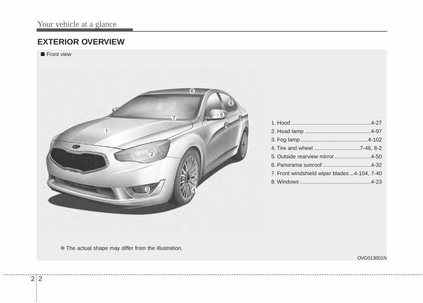
EXTERIOR OVERVIEW
1. Hood .....................................................4-27
2. Head lamp ............................................4-97
3. Fog lamp.............................................4-102
4. Tire and wheel...............................7-46, 8-2
5. Outside rearview mirror ........................4-50
6. Panorama sunroof ................................4-32
7. Front windshield wiper blades ...4-104, 7-40
8. Windows ...............................................4-23
OVG013001N
■ Front view
❈ The actual shape may differ from the illustration.
2 3
Your vehicle at a glance
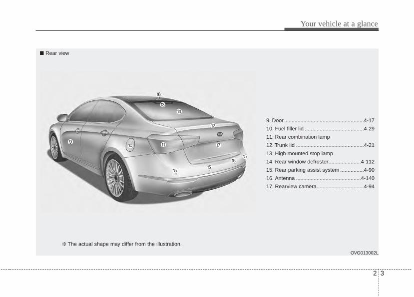
9. Door ......................................................4-17
10. Fuel filler lid ........................................4-29
11. Rear combination lamp
12. Trunk lid ..............................................4-21
13. High mounted stop lamp
14. Rear window defroster......................4-112
15. Rear parking assist system ................4-90
16. Antenna ............................................4-140
17. Rearview camera................................4-94
OVG013002L
■ Rear view
❈ The actual shape may differ from the illustration.
Your vehicle at a glance
42
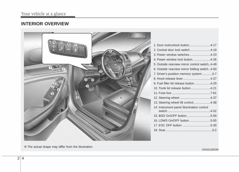
INTERIOR OVERVIEW
1. Door lock/unlock button.........................4-17
2. Central door lock switch........................4-19
3. Power window switches ........................4-23
4. Power window lock button.....................4-26
5. Outside rearview mirror control switch..4-49
6. Outside rearview mirror folding switch ..4-50
7. Driver's position memory system............3-7
8. Hood release lever ................................4-27
9. Fuel filler lid release button...................4-29
10. Trunk lid release button.......................4-21
11. Fuse box .............................................7-61
12. Steering wheel ....................................4-37
13. Steering wheel tilt control....................4-38
14. Instrument panel illumination controlswitch ..................................................4-52
15. BSD On/OFF button............................5-59
16. LDWS On/OFF button.........................5-55
17. ESC OFF button .................................5-30
18. Seat.......................................................3-2
OVG013003N❈ The actual shape may differ from the illustration.
2 5
Your vehicle at a glance
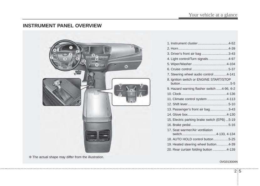
INSTRUMENT PANEL OVERVIEW
1. Instrument cluster .................................4-52
2. Horn......................................................4-39
3. Driver's front air bag .............................3-43
4. Light control/Turn signals......................4-97
5. Wiper/Washer .....................................4-104
6. Cruise control .......................................5-37
7. Steering wheel audio control ..............4-141
8. Ignition switch or ENGINE START/STOPbutton......................................................5-5
9. Hazard warning flasher switch ......4-96, 6-2
10. Clock.................................................4-136
11. Climate control system .....................4-113
12. Shift lever............................................5-10
13. Passenger's front air bag....................3-43
14. Glove box..........................................4-130
15. Electric parking brake switch (EPB) ...5-19
16. Brake pedal.........................................5-16
17. Seat warmer/Air ventilationswitch.....................................4-133, 4-134
18. AUTO HOLD control button ................5-25
19. Heated steering wheel button.............4-39
20. Rear curtain folding button ...............4-139
OVG013004N
❈ The actual shape may differ from the illustration.
Your vehicle at a glance
62
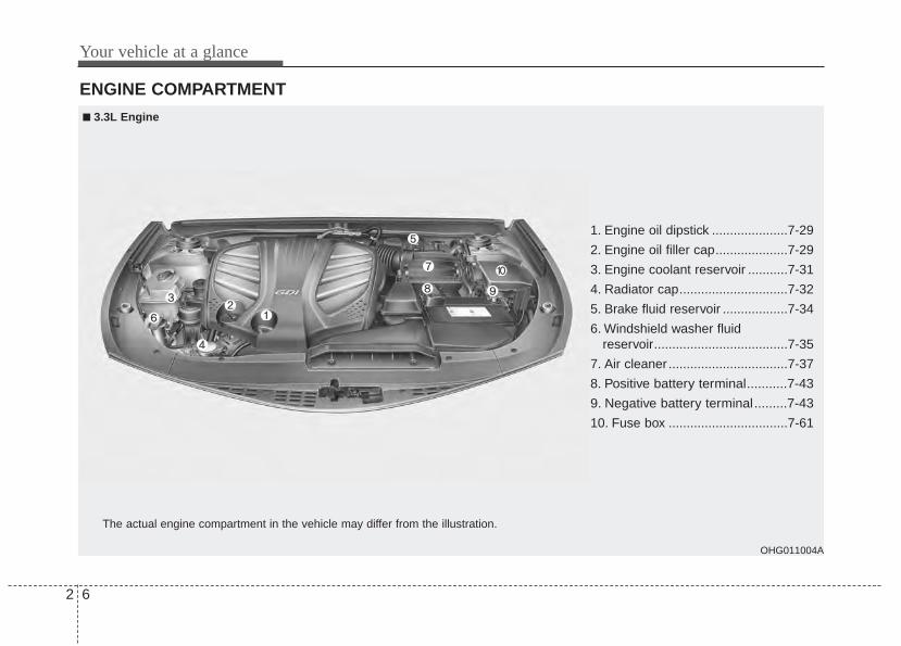
ENGINE COMPARTMENT
OHG011004A
The actual engine compartment in the vehicle may differ from the illustration.
1. Engine oil dipstick .....................7-29
2. Engine oil filler cap....................7-29
3. Engine coolant reservoir ...........7-31
4. Radiator cap..............................7-32
5. Brake fluid reservoir ..................7-34
6. Windshield washer fluidreservoir.....................................7-35
7. Air cleaner .................................7-37
8. Positive battery terminal...........7-43
9. Negative battery terminal.........7-43
10. Fuse box .................................7-61
■■ 3.3L Engine
Safety features of your vehicle
Seat. . . . . . . . . . . . . . . . . . . . . . . . . . . . . . . . . . . . . . . 3-2• Front seat adjustment - power. . . . . . . . . . . . . . . . . . . 3-4• Driver position memory system . . . . . . . . . . . . . . . . . . 3-7• Headrest (for front seat) . . . . . . . . . . . . . . . . . . . . . . . . 3-9• Seatback pocket . . . . . . . . . . . . . . . . . . . . . . . . . . . . . . 3-10• Rear seat adjustment . . . . . . . . . . . . . . . . . . . . . . . . . 3-11• Headrest (for rear seat). . . . . . . . . . . . . . . . . . . . . . . . 3-11
Seat belt . . . . . . . . . . . . . . . . . . . . . . . . . . . . . . . . . . 3-13• Seat belt restraint system . . . . . . . . . . . . . . . . . . . . . . 3-13• Pre-tensioner seat belt. . . . . . . . . . . . . . . . . . . . . . . . . 3-18• Seat belt precautions . . . . . . . . . . . . . . . . . . . . . . . . . . 3-21
Child restraint system . . . . . . . . . . . . . . . . . . . . . . 3-24• Using a child restraint system . . . . . . . . . . . . . . . . . . 3-25• Tether anchor system . . . . . . . . . . . . . . . . . . . . . . . . . 3-28• Lower anchor system . . . . . . . . . . . . . . . . . . . . . . . . . 3-29
Air bag - supplemental restraint system . . . . . . . 3-31• Air bag system operation . . . . . . . . . . . . . . . . . . . . . . 3-32• Do not install a child restraint on the front
passenger's seat . . . . . . . . . . . . . . . . . . . . . . . . . . . . 3-33• Air bag warning light . . . . . . . . . . . . . . . . . . . . . . . . . 3-34• SRS components and functions . . . . . . . . . . . . . . . . . 3-35• Occupant Detection System (ODS) . . . . . . . . . . . . . . 3-37• Driver's and passenger's front air bag . . . . . . . . . . . 3-43
• Side air bag . . . . . . . . . . . . . . . . . . . . . . . . . . . . . . . . . 3-45• Curtain air bag . . . . . . . . . . . . . . . . . . . . . . . . . . . . . . 3-46• Inflation and non-inflation conditions
of the air bag. . . . . . . . . . . . . . . . . . . . . . . . . . . . . . . 3-48• SRS Care . . . . . . . . . . . . . . . . . . . . . . . . . . . . . . . . . . . 3-53• Air bag warning label . . . . . . . . . . . . . . . . . . . . . . . . . 3-54
3
Safety features of your vehicle
23
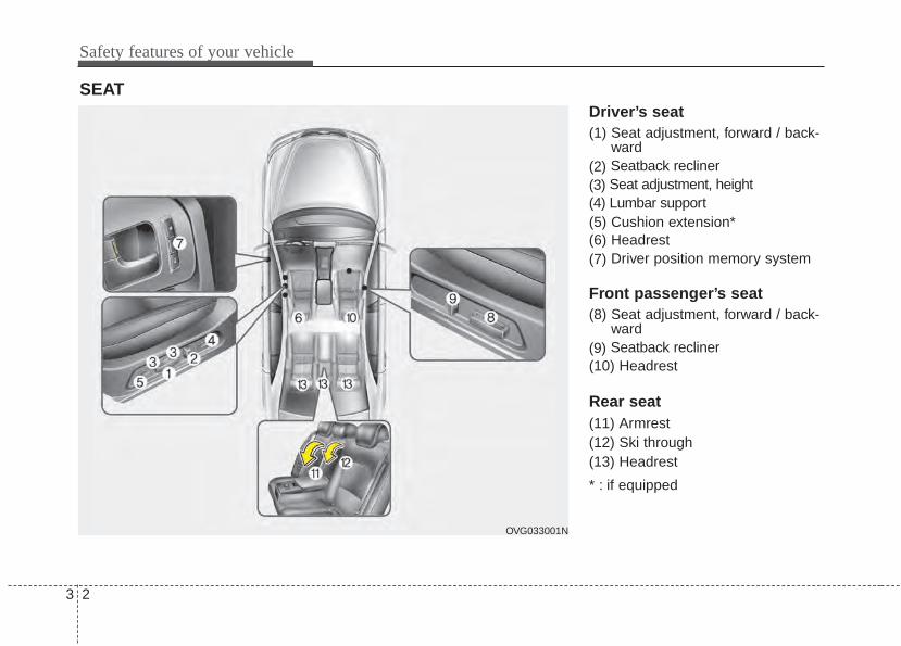
Driver’s seat(1) Seat adjustment, forward / back-
ward(2) Seatback recliner(3) Seat adjustment, height(4) Lumbar support(5) Cushion extension*(6) Headrest(7) Driver position memory system
Front passenger’s seat(8) Seat adjustment, forward / back-
ward(9) Seatback recliner(10) Headrest
Rear seat(11) Armrest(12) Ski through(13) Headrest
* : if equipped
SEAT
OVG033001N
3 3
Safety features of your vehicle
WARNING - Uprightingseat
Do not press the release leveron a manual seatback withoutholding and controlling theseatback. The seatback willspring upright possibly impact-ing you or other passengers.
WARNING - Looseobjects
Do not place anything in the dri-ver's foot well or under the frontseats. Loose objects in the dri-ver's foot area could interferewith the operation of the footpedals.
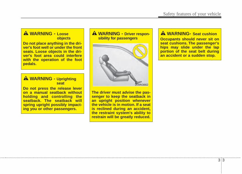
WARNING - Driver respon-sibility for passengers
The driver must advise the pas-senger to keep the seatback inan upright position wheneverthe vehicle is in motion. If a seatis reclined during an accident,the restraint system's ability torestrain will be greatly reduced.
WARNING- Seat cushionOccupants should never sit onseat cushions. The passenger'ships may slide under the lapportion of the seat belt duringan accident or a sudden stop.
1KMN3662
Safety features of your vehicle
43
Front seat adjustment - powerThe front seat can be adjusted byusing the control switch located onthe outside of the seat cushion.Before driving, adjust the seat to theproper position so as to easily con-trol the steering wheel, pedals andswitches on the instrument panel.
WARNING - Seat adjustment
• Do not adjust the seat whilewearing seat belts. Moving theseat forward will cause strongpressure on the abdomen.
• Do not place your hand nearthe seat bottom or seat trackwhile adjusting the seat. Yourhand could get caught in theseat mechanism.
WARNINGThe power seat is operable withthe ignition OFF.Therefore, children should neverbe left unatteded in the vehicle.
WARNING - Driver’s seat• Never attempt to adjust the
seat while the vehicle is mov-ing. This could result in lossof control of your vehicle.
• Do not allow anything to inter-fere with the normal positionof the seatback. Storing itemsagainst a seatback or in anyother way interfering withproper locking of a seatbackcould result in a serious orfatal injury in a sudden stopor collision.
• Sit as far back as possiblefrom the steering wheel whilestill maintaining comfortablecontrol of your vehicle. A dis-tance of at least 10" from yourchest to the steering wheel isrecommended. Failure to doso could result in air bag infla-tion injuries to the driver.
3 5
Safety features of your vehicle
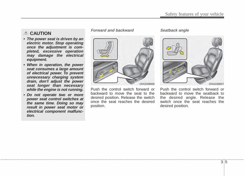
Forward and backward
Push the control switch forward orbackward to move the seat to thedesired position. Release the switchonce the seat reaches the desiredposition.
Seatback angle
Push the control switch forward orbackward to move the seatback tothe desired angle. Release theswitch once the seat reaches thedesired position.
CAUTION• The power seat is driven by an
electric motor. Stop operatingonce the adjustment is com-pleted, excessive operationmay damage the electricalequipment.
• When in operation, the powerseat consumes a large amountof electrical power. To preventunnecessary charging systemdrain, don’t adjust the powerseat longer than necessarywhile the engine is not running.
• Do not operate two or morepower seat control switches atthe same time. Doing so mayresult in power seat motor orelectrical component malfunc-tion.
OVG039006 OVG039007
Safety features of your vehicle
63
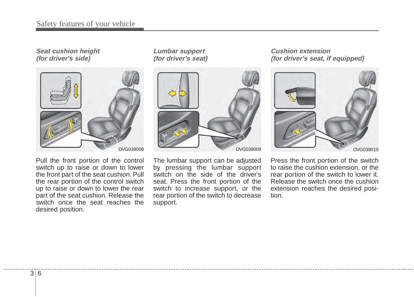
Seat cushion height (for driver's side)
Pull the front portion of the controlswitch up to raise or down to lowerthe front part of the seat cushion. Pullthe rear portion of the control switchup to raise or down to lower the rearpart of the seat cushion. Release theswitch once the seat reaches thedesired position.
Lumbar support (for driver’s seat)
The lumbar support can be adjustedby pressing the lumbar supportswitch on the side of the driver'sseat. Press the front portion of theswitch to increase support, or therear portion of the switch to decreasesupport.
Cushion extension (for driver's seat, if equipped)
Press the front portion of the switchto raise the cushion extension, or therear portion of the switch to lower it.Release the switch once the cushionextension reaches the desired posi-tion.
OVG039009OVG039008 OVG039010
3 7
Safety features of your vehicle
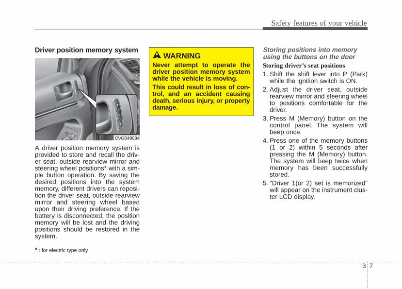
Driver position memory system
A driver position memory system isprovided to store and recall the driv-er seat, outside rearview mirror andsteering wheel positions* with a sim-ple button operation. By saving thedesired positions into the systemmemory, different drivers can reposi-tion the driver seat, outside rearviewmirror and steering wheel basedupon their driving preference. If thebattery is disconnected, the positionmemory will be lost and the drivingpositions should be restored in thesystem.
* : for electric type only
Storing positions into memoryusing the buttons on the doorStoring driver’s seat positions1. Shift the shift lever into P (Park)
while the ignition switch is ON.2. Adjust the driver seat, outside
rearview mirror and steering wheelto positions comfortable for thedriver.
3. Press M (Memory) button on thecontrol panel. The system willbeep once.
4. Press one of the memory buttons(1 or 2) within 5 seconds afterpressing the M (Memory) button.The system will beep twice whenmemory has been successfullystored.
5. "Driver 1(or 2) set is memorized"will appear on the instrument clus-ter LCD display.
OVG049034
WARNING Never attempt to operate thedriver position memory systemwhile the vehicle is moving.This could result in loss of con-trol, and an accident causingdeath, serious injury, or propertydamage.
Safety features of your vehicle
83
Recalling positions from memory1. The shift lever should be in P
(Park) when :- The ignition switch is in ON or
engine is running.- It is less than 20 minutes after the
driver's door is opened with theignition switch in OFF or ACC.
- It is less than 30 seconds afterthe driver's door is closed withthe ignition switch in OFF orACC.
2. To recall the position in memory,press the desired memory button(1 or 2). The system will beeponce, then the driver seat, outsiderearview mirror and steeringwheel will automatically adjust tothe stored positions.
3. "Driver 1 (or 2) set is changed" willappear on the instrument clusterLCD display.
Adjusting the control switch for thedriver seat while the system is recall-ing the stored position will cause themovement to stop and move in thedirection that the control switch ismoved.
Easy access function With the shift lever in the P position,the system will move the driver's seatautomatically as follows:• It will move the driver’s seat rear-
ward when the engine start/stopbutton is turned to the OFF position.
• It will move the driver’s seat forwardwhen the engine start/stop button isturned to the ACC or START posi-tion.
You can activate or deactivate thisfeature. Refer to "User settings" inchapter 4.
WARNING Use caution when recallingadjustment memory while sittingin the vehicle. Push the seatposition control knob to thedesired position immediately ifthe seat moves too far in anydirection.
3 9
Safety features of your vehicle
Headrest (for front seat)
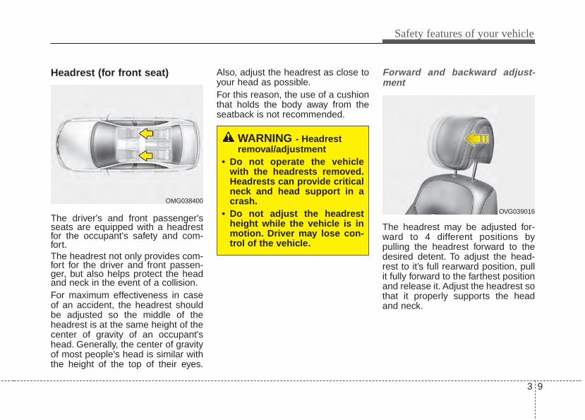
The driver's and front passenger'sseats are equipped with a headrestfor the occupant's safety and com-fort.The headrest not only provides com-fort for the driver and front passen-ger, but also helps protect the headand neck in the event of a collision.For maximum effectiveness in caseof an accident, the headrest shouldbe adjusted so the middle of theheadrest is at the same height of thecenter of gravity of an occupant'shead. Generally, the center of gravityof most people's head is similar withthe height of the top of their eyes.
Also, adjust the headrest as close toyour head as possible.For this reason, the use of a cushionthat holds the body away from theseatback is not recommended.
Forward and backward adjust-ment
The headrest may be adjusted for-ward to 4 different positions bypulling the headrest forward to thedesired detent. To adjust the head-rest to it’s full rearward position, pullit fully forward to the farthest positionand release it. Adjust the headrest sothat it properly supports the headand neck.
OMG038400
WARNING - Headrestremoval/adjustment
• Do not operate the vehiclewith the headrests removed.Headrests can provide criticalneck and head support in acrash.
• Do not adjust the headrestheight while the vehicle is inmotion. Driver may lose con-trol of the vehicle.
OVG039016
Safety features of your vehicle
103
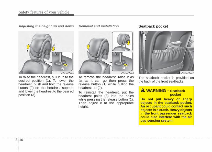
Adjusting the height up and down
To raise the headrest, pull it up to thedesired position (1). To lower theheadrest, push and hold the releasebutton (2) on the headrest supportand lower the headrest to the desiredposition (3).
Removal and installation
To remove the headrest, raise it asfar as it can go then press therelease button (1) while pulling theheadrest up (2).To reinstall the headrest, put theheadrest poles (3) into the holeswhile pressing the release button (1).Then adjust it to the appropriateheight.
Seatback pocket
The seatback pocket is provided onthe back of the front seatbacks.
OVG039012OVG039011
WARNING - Seatbackpocket
Do not put heavy or sharpobjects in the seatback pocket.An occupant could contact suchobjects in a crash. Heavy objectsin the front passenger seatbackcould also interfere with the airbag sensing system.
OVG039017
3 11
Safety features of your vehicle
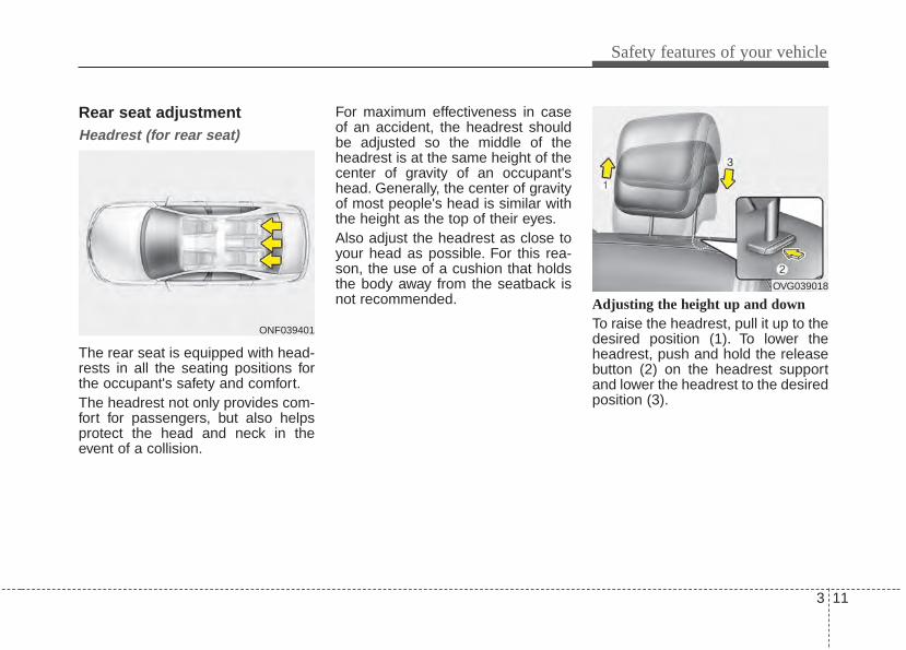
Rear seat adjustmentHeadrest (for rear seat)
The rear seat is equipped with head-rests in all the seating positions forthe occupant's safety and comfort.The headrest not only provides com-fort for passengers, but also helpsprotect the head and neck in theevent of a collision.
For maximum effectiveness in caseof an accident, the headrest shouldbe adjusted so the middle of theheadrest is at the same height of thecenter of gravity of an occupant'shead. Generally, the center of gravityof most people's head is similar withthe height as the top of their eyes.Also adjust the headrest as close toyour head as possible. For this rea-son, the use of a cushion that holdsthe body away from the seatback isnot recommended. Adjusting the height up and down
To raise the headrest, pull it up to thedesired position (1). To lower theheadrest, push and hold the releasebutton (2) on the headrest supportand lower the headrest to the desiredposition (3).
ONF039401
OVG039018

Safety features of your vehicle
123
Removal and installationTo remove the headrest, raise it as faras it can go then press the releasebutton (1) while pulling the headrestupward (2).To reinstall the headrest, put theheadrest poles (3) into the holes whilepressing the release button (1). Thenadjust it to the appropriate height andensure that it locks in position.Make sure the headrest locks in posi-tion after adjusting.
Armrest
To use the armrest, pull it forwardfrom the seatback.
OVG039019
OVG033311N
3 13
Safety features of your vehicle
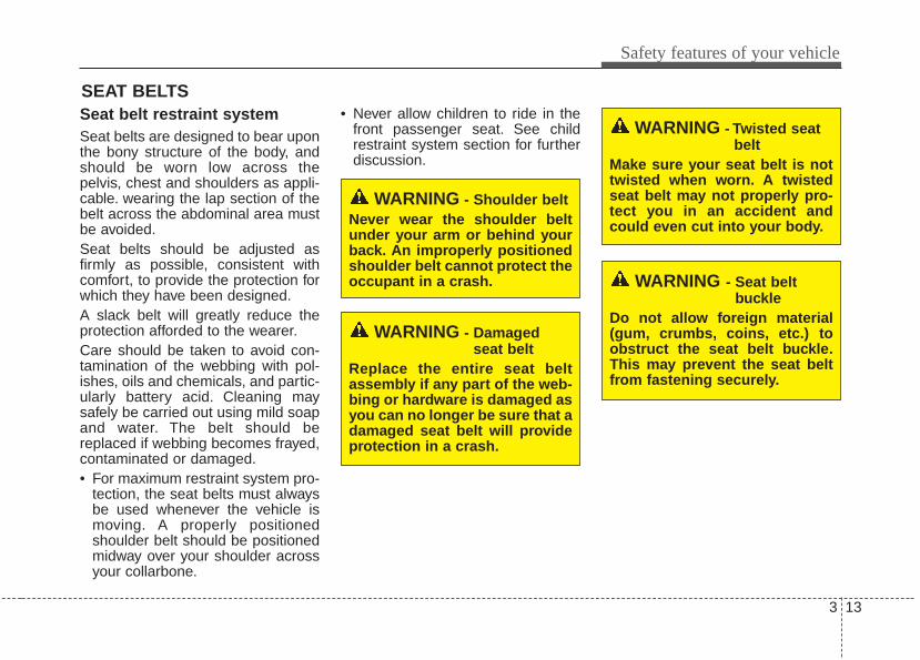
Seat belt restraint systemSeat belts are designed to bear uponthe bony structure of the body, andshould be worn low across thepelvis, chest and shoulders as appli-cable. wearing the lap section of thebelt across the abdominal area mustbe avoided.Seat belts should be adjusted asfirmly as possible, consistent withcomfort, to provide the protection forwhich they have been designed.A slack belt will greatly reduce theprotection afforded to the wearer.Care should be taken to avoid con-tamination of the webbing with pol-ishes, oils and chemicals, and partic-ularly battery acid. Cleaning maysafely be carried out using mild soapand water. The belt should bereplaced if webbing becomes frayed,contaminated or damaged.• For maximum restraint system pro-
tection, the seat belts must alwaysbe used whenever the vehicle ismoving. A properly positionedshoulder belt should be positionedmidway over your shoulder acrossyour collarbone.
• Never allow children to ride in thefront passenger seat. See childrestraint system section for furtherdiscussion.
SEAT BELTS
WARNING - Shoulder beltNever wear the shoulder beltunder your arm or behind yourback. An improperly positionedshoulder belt cannot protect theoccupant in a crash.
WARNING - Damagedseat belt
Replace the entire seat beltassembly if any part of the web-bing or hardware is damaged asyou can no longer be sure that adamaged seat belt will provideprotection in a crash.
WARNING - Twisted seatbelt
Make sure your seat belt is nottwisted when worn. A twistedseat belt may not properly pro-tect you in an accident andcould even cut into your body.
WARNING - Seat belt buckle
Do not allow foreign material(gum, crumbs, coins, etc.) toobstruct the seat belt buckle.This may prevent the seat beltfrom fastening securely.
Safety features of your vehicle
143
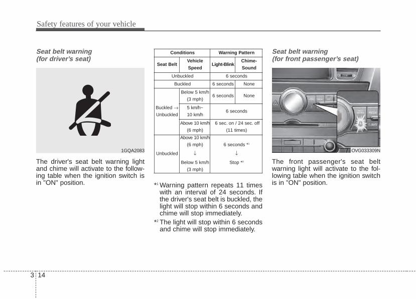
Seat belt warning (for driver’s seat)
The driver's seat belt warning lightand chime will activate to the follow-ing table when the ignition switch isin "ON" position. *1 Warning pattern repeats 11 times
with an interval of 24 seconds. Ifthe driver's seat belt is buckled, thelight will stop within 6 seconds andchime will stop immediately.
*2 The light will stop within 6 secondsand chime will stop immediately.
Seat belt warning (for front passenger’s seat)
The front passenger's seat beltwarning light will activate to the fol-lowing table when the ignition switchis in "ON" position.
1GQA2083 OVG033309N
Conditions Warning Pattern
Seat BeltVehicle
SpeedLight-Blink
Chime-
Sound
Unbuckled 6 seconds
Buckled 6 seconds None
Buckled →Unbuckled
Below 5 km/h
(3 mph)6 seconds None
5 km/h~
10 km/h6 seconds
Above 10 km/h
(6 mph)
6 sec. on / 24 sec. off
(11 times)
Unbuckled
Above 10 km/h
(6 mph)
↓
Below 5 km/h
(3 mph)
6 seconds *1
↓
Stop *2
3 15
Safety features of your vehicle
*1 The seat belt warning light will gooff if the vehicle speed decreasesbelow 5 km/h (3 mph). If the vehi-cle speed increases above 5 km/h(3 mph), the warning light will blinkagain.
• You can find the front passenger'sseat belt warning light on the cen-ter fascia panel.
• Although the front passenger seatis not occupied, the seat belt warn-ing light will blink for 6 seconds.
• The seat belt warning light canblink when a briefcase or purse isplaced on the front passengerseat.
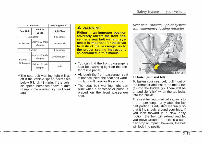
Seat belt - Driver's 3-point systemwith emergency locking retractor
To fasten your seat belt:To fasten your seat belt, pull it out ofthe retractor and insert the metal tab(1) into the buckle (2). There will bean audible "click" when the tab locksinto the buckle.The seat belt automatically adjusts tothe proper length only after the lapbelt portion is adjusted manually sothat it fits snugly around your hips. Ifyou lean forward in a slow, easymotion, the belt will extend and letyou move around. If there is a sud-den stop or impact, however, the beltwill lock into position.
Conditions Warning Pattern
Seat BeltVehicle
SpeedLight-Blink
Unbuckled 6 seconds
UnbuckledAbove 10 km/h
(6mph)Continuously
Buckled 6 seconds
Buckled →Unbuckled
Above 10 km/h(6mph)
Continuously *1
Below 10 km/h
(6mph)None
B180A01NF-1
WARNINGRiding in an improper positionadversely affects the front pas-senger's seat belt warning sys-tem. It is important for the driverto instruct the passenger as tothe proper seating instructionsas contained in this manual.
Safety features of your vehicle
163
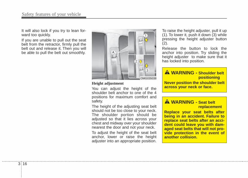
It will also lock if you try to lean for-ward too quickly.If you are unable to pull out the seatbelt from the retractor, firmly pull thebelt out and release it. Then you willbe able to pull the belt out smoothly.
Height adjustment You can adjust the height of theshoulder belt anchor to one of the 4positions for maximum comfort andsafety.The height of the adjusting seat beltshould not be too close to your neck.The shoulder portion should beadjusted so that it lies across yourchest and midway over your shouldernearest the door and not your neck.To adjust the height of the seat beltanchor, lower or raise the heightadjuster into an appropriate position.
To raise the height adjuster, pull it up(1). To lower it, push it down (3) whilepressing the height adjuster button(2).Release the button to lock theanchor into position. Try sliding theheight adjuster to make sure that ithas locked into position.
WARNING - Shoulder beltpositioning
Never position the shoulder beltacross your neck or face.
WARNING - Seat beltreplacement
Replace your seat belts afterbeing in an accident. Failure toreplace seat belts after an acci-dent could leave you with dam-aged seat belts that will not pro-vide protection in the event ofanother collision.
OMG035038
3 17
Safety features of your vehicle
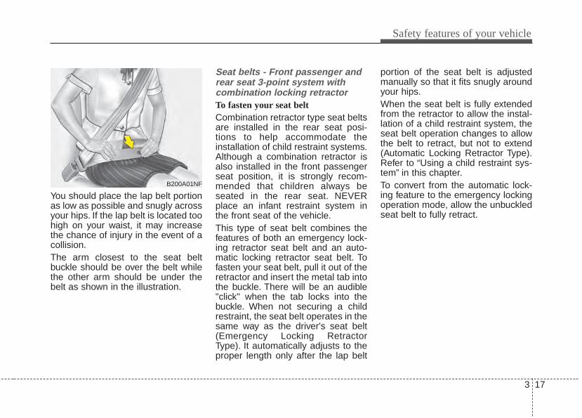
You should place the lap belt portionas low as possible and snugly acrossyour hips. If the lap belt is located toohigh on your waist, it may increasethe chance of injury in the event of acollision.The arm closest to the seat beltbuckle should be over the belt whilethe other arm should be under thebelt as shown in the illustration.
Seat belts - Front passenger andrear seat 3-point system withcombination locking retractorTo fasten your seat beltCombination retractor type seat beltsare installed in the rear seat posi-tions to help accommodate theinstallation of child restraint systems.Although a combination retractor isalso installed in the front passengerseat position, it is strongly recom-mended that children always beseated in the rear seat. NEVERplace an infant restraint system inthe front seat of the vehicle.This type of seat belt combines thefeatures of both an emergency lock-ing retractor seat belt and an auto-matic locking retractor seat belt. Tofasten your seat belt, pull it out of theretractor and insert the metal tab intothe buckle. There will be an audible"click" when the tab locks into thebuckle. When not securing a childrestraint, the seat belt operates in thesame way as the driver's seat belt(Emergency Locking RetractorType). It automatically adjusts to theproper length only after the lap belt
portion of the seat belt is adjustedmanually so that it fits snugly aroundyour hips.When the seat belt is fully extendedfrom the retractor to allow the instal-lation of a child restraint system, theseat belt operation changes to allowthe belt to retract, but not to extend(Automatic Locking Retractor Type).Refer to “Using a child restraint sys-tem” in this chapter.To convert from the automatic lock-ing feature to the emergency lockingoperation mode, allow the unbuckledseat belt to fully retract.
B200A01NF

Safety features of your vehicle
183
When using the rear center seat belt,the buckle with the “CENTER” markmust be used.
To release the seat belt The seat belt is released by pressingthe release button (1) of the lockingbuckle. When it is released, the beltshould automatically draw back intothe retractor.If this does not happen, check thebelt to be sure it is not twisted, thentry again.
Pre-tensioner seat belt
Your vehicle is equipped with driver'sand front passenger's pre-tensionerseat belts (retractor pretensioner andEFD (Emergency Fastening Device).The pre-tensioner seat belts may beactivated, when a frontal collision issevere enough, together with the airbags.When the vehicle stops suddenly, orif the occupant tries to lean forwardtoo quickly, the seat belt retractormay lock into position. In certainfrontal collisions, the pre-tensionerwill activate and pull the seat belt intotighter contact against the occu-pant's body.
B210A01NF-1OBH038023N
OXMA033101
3 19
Safety features of your vehicle
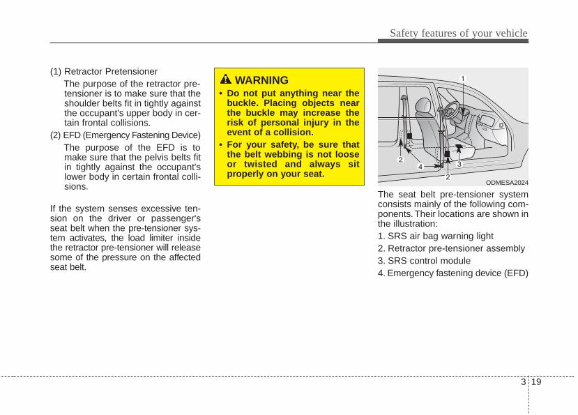
(1) Retractor PretensionerThe purpose of the retractor pre-tensioner is to make sure that theshoulder belts fit in tightly againstthe occupant's upper body in cer-tain frontal collisions.
(2) EFD (Emergency Fastening Device)The purpose of the EFD is tomake sure that the pelvis belts fitin tightly against the occupant'slower body in certain frontal colli-sions.
If the system senses excessive ten-sion on the driver or passenger'sseat belt when the pre-tensioner sys-tem activates, the load limiter insidethe retractor pre-tensioner will releasesome of the pressure on the affectedseat belt.
The seat belt pre-tensioner systemconsists mainly of the following com-ponents.Their locations are shown inthe illustration:1. SRS air bag warning light2. Retractor pre-tensioner assembly3. SRS control module4. Emergency fastening device (EFD)
WARNING• Do not put anything near the
buckle. Placing objects nearthe buckle may increase therisk of personal injury in theevent of a collision.
• For your safety, be sure thatthe belt webbing is not looseor twisted and always sitproperly on your seat.
ODMESA2024
Safety features of your vehicle
203
✽✽ NOTICE• Both the driver's and front pas-
senger's seat belt pre-tensionersystem may be activated not onlyin certain frontal collision but alsoin certain side collision or rollover,if the vehicle is equipped with aside or curtain air bag.
• When the pre-tensioner seat beltsare activated, a loud noise may beheard and fine dust, which mayappear to be smoke, may be visiblein the passenger compartment.These are normal operating condi-tions and are not hazardous.
• Although it is harmless, the finedust may cause skin irritation andshould not be breathed for pro-longed periods. Wash all exposedskin areas thoroughly after anaccident in which the pre-tension-er seat belts were activated.
• Because the sensor that activatesthe SRS air bag is connected withthe pre-tensioner seat belt, theSRS air bag warning light onthe instrument panel will illumi-nate for approximately 6 secondsafter the ignition switch has beenturned to the ON position, andthen it should turn off.
WARNINGTo obtain maximum benefitfrom a pre-tensioner seat belt:1. The seat belt must be worn
correctly and adjusted to theproper position. Please readand follow all of the importantinformation and precautionsabout your vehicle’s occupantsafety features – includingseat belts and air bags – thatare provided in this manual.
2. Be sure you and your passen-gers always wear seat beltsproperly.
CAUTIONIf the pre-tensioner seat beltsystem are not working proper-ly, this warning light will illumi-nate even if there is no malfunc-tion of the SRS air bag. If theSRS air bag warning light doesnot illuminate when the ignitionswitch is turned ON, or if itremains illuminated after illumi-nating for approximately 6 sec-onds, or if it illuminates whilethe vehicle is being driven, havean authorized Kia dealer inspectthe pre-tensioner seat belt andSRS air bag system as soon aspossible.
3 21
Safety features of your vehicle
Seat belt precautionsInfant or small childYou should be aware of the specificrequirements in your country. Childand/or infant seats must be properlyplaced and installed in the rear seat.For more information about the useof these restraints, refer to “Childrestraint system” in this chapter.
WARNING• Pre-tensioners are designed
to operate only one time. Afteractivation, pre-tensioner seatbelts must be replaced. Allseat belts, of any type, shouldalways be replaced after theyhave been worn during a colli-sion.
• The pre-tensioner seat beltassembly mechanisms becomehot during activation. Do nottouch the pre-tensioner seatbelt assemblies for several min-utes after they have been acti-vated.
• Do not attempt to inspect orreplace the pre-tensioner seatbelts yourself. This must bedone by an authorized Kiadealer.
• Do not strike the pre-tension-er seat belt assemblies.
• Do not attempt to service orrepair the pre-tensioner seatbelt system in any manner.
(Continued)
(Continued)• Improper handling of the pre-
tensioner seat belt assem-blies, and failure to heed thewarnings not to strike, modify,inspect, replace, service orrepair the pre-tensioner seatbelt assemblies may lead toimproper operation or inad-vertent activation and seriousinjury.
• Always wear the seat beltswhen driving or riding in amotor vehicle.
• If the vehicle or pre-tensionerseat belt must be discarded,contact an authorized Kiadealer.
Safety features of your vehicle
223
Larger childrenChildren who are too large for childrestraint systems should always occu-py the rear seat and use the availablelap/shoulder belts. The lap portionshould be fastened snug on the hipsand as low as possible. Periodicallycheck belt fit. A child's squirming couldput the belt out of position. Childrenare given the most safety in the eventof an accident when they arerestrained by a proper restraint systemin the rear seat. If a larger child (overage 12) must be seated in the frontseat, the child should be securelyrestrained by the available lap/shoul-der belt and the seat should be placedin the rearmost position. Children age12 and under should be restrainedsecurely in the rear seat. NEVERplace a child age 12 and under in thefront seat. NEVER place a rear facingchild seat in the front seat of a vehicle.If the shoulder belt portion slightlytouches the child’s neck or face, tryplacing the child closer to the center ofthe vehicle. If the shoulder belt stilltouches their face or neck they need tobe returned to a child restraint system.
Restraint of pregnant women Pregnant women should wearlap/shoulder belt assemblies when-ever possible according to specificrecommendations by their doctors.The lap portion of the belt should beworn AS SNUGLY AND LOW ASPOSSIBLE on the hips, not acrossthe abdomen.
WARNING - Small chil-dren
Do not allow small children toride in the vehicle without anappropriate child restraint sys-tem.
WARNING - Pregnantwomen
Pregnant women must neverplace the lap portion of the seatbelt above or on the abdomenwhere the fetus is located. Theforce of the seat belt during acollision will crush the fetus.
3 23
Safety features of your vehicle
Injured personA seat belt should be used when aninjured person is being transported.When this is necessary, you shouldconsult a physician for recommenda-tions.
One person per beltTwo people (including children)should never attempt to use a singleseat belt. This could increase theseverity of injuries in case of an acci-dent.
Do not lie downTo reduce the chance of injuries in theevent of an accident and to achievemaximum effectiveness of therestraint system, all passengersshould be sitting up and the frontseats should be in an upright positionwhen the vehicle is moving. A seatbelt cannot provide proper protectionif the person is lying down in the rearseat or if the front seat is in a reclinedposition.
Care of seat beltsSeat belt systems should never bedisassembled or modified. In addi-tion, care should be taken to assurethat seat belts and belt hardware arenot damaged by seat hinges, doorsor other abuse.
Periodic inspectionAll seat belts should be inspectedperiodically for wear or damage ofany kind. Any damaged parts shouldbe replaced as soon as possible.
Keep belts clean and drySeat belts should be kept clean anddry. If belts become dirty, they can becleaned by using a mild soap solu-tion and warm water. Bleach, dye,strong detergents or abrasivesshould not be used because theymay damage and weaken the fabric.
When to replace seat beltsThe entire in-use seat belt assemblyor assemblies should be replaced ifthe vehicle has been involved in anaccident. This should be done even ifno damage is visible. Additionalquestions concerning seat belt oper-ation should be directed to anauthorized Kia dealer.
Safety features of your vehicle
243
CHILD RESTRAINT SYSTEMChildren riding in the car should sit inthe rear seat and must always beproperly restrained to minimize therisk of injury in an accident, suddenstop or sudden maneuver. Accordingto accident statistics, children aresafer when properly restrained in therear seats than in the front seat.Larger children who are not in a childrestraint should use one of the seatbelts provided.You should be aware of the specificrequirements in your country. Childand/or infant safety seats must beproperly placed and installed in therear seat. You must use a commer-cially available child restraint systemthat meets the requirements of thesafety standards of your country.Child restraint systems are designedto be secured in vehicle seats byseat belt, or by a tether anchorand/or LATCH anchors (if equipped).
Children could be injured or killed ina crash if their restraints are notproperly secured. For small childrenand babies, a child seat or infant seatmust be used. Before buying a par-ticular child restraint system, makesure it fits your car seat and seatbelts, and fits your child. Follow allthe instructions provided by the man-ufacturer when installing the childrestraint system.
When the child restraint system is notin use, store it in the luggage area orfasten it with a seat belt so that it willnot be thrown forward in case of asudden stop or an accident.
WARNING- Restraint location
Never install a child or infant seaton the front passenger's seat.A child riding in the front pas-senger seat can be forcefullystruck by an inflating air bag.
WARNING- Hot childrestraint
A child restraint system canbecome very hot if it is left in aclosed vehicle on a sunny day.Be sure to check the seat cover,buckles and latches beforeplacing a child in the restraintsystem.
3 25
Safety features of your vehicle
Using a child restraint system
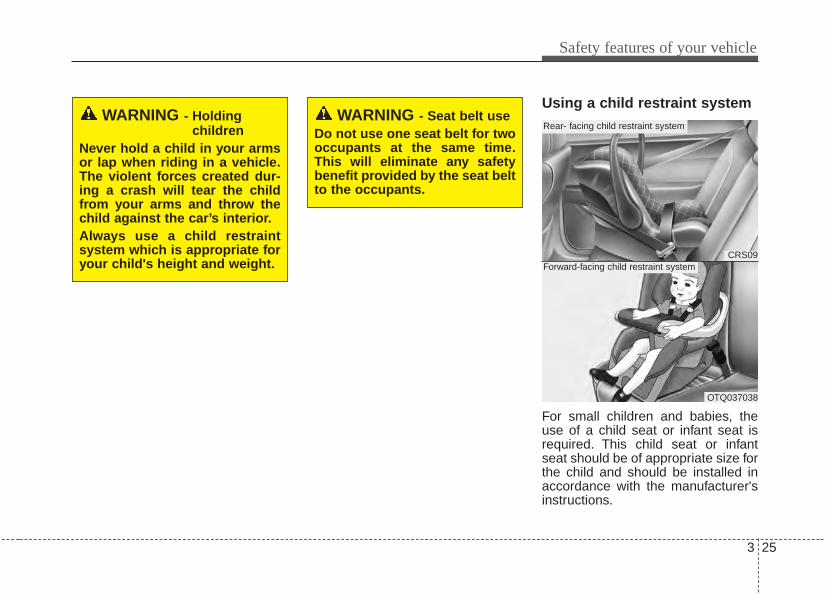
For small children and babies, theuse of a child seat or infant seat isrequired. This child seat or infantseat should be of appropriate size forthe child and should be installed inaccordance with the manufacturer'sinstructions.
WARNING - Holding children
Never hold a child in your armsor lap when riding in a vehicle.The violent forces created dur-ing a crash will tear the childfrom your arms and throw thechild against the car’s interior.Always use a child restraintsystem which is appropriate foryour child's height and weight.
WARNING - Seat belt useDo not use one seat belt for twooccupants at the same time.This will eliminate any safetybenefit provided by the seat beltto the occupants.
CRS09
OTQ037038
Rear- facing child restraint system
Forward-facing child restraint system
Safety features of your vehicle
263
For safety reasons, we recommendthat the child restraint system beused in the rear seats.Since all passenger seat belts movefreely under normal conditions andonly lock under extreme or emer-gency conditions (emergency lockmode), you must manually changethese seat belts to the auto lockmode to secure a child restraint.If the seat belt does not operate asdescribed in this section, have thesystem checked immediately by yourauthorized Kia dealer.
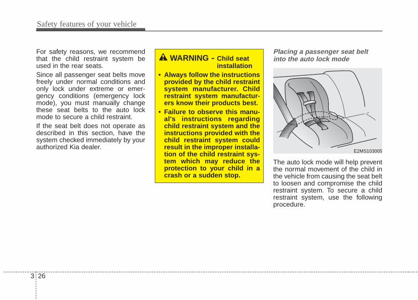
Placing a passenger seat beltinto the auto lock mode
The auto lock mode will help preventthe normal movement of the child inthe vehicle from causing the seat beltto loosen and compromise the childrestraint system. To secure a childrestraint system, use the followingprocedure.
WARNING - Child seatinstallation
• Always follow the instructionsprovided by the child restraintsystem manufacturer. Childrestraint system manufactur-ers know their products best.
• Failure to observe this manu-al's instructions regardingchild restraint system and theinstructions provided with thechild restraint system couldresult in the improper installa-tion of the child restraint sys-tem which may reduce theprotection to your child in acrash or a sudden stop.
E2MS103005
3 27
Safety features of your vehicle
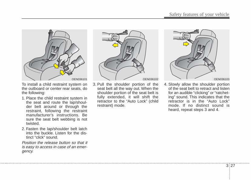
To install a child restraint system onthe outboard or center rear seats, dothe following:1. Place the child restraint system in
the seat and route the lap/shoul-der belt around or through therestraint, following the restraintmanufacturer’s instructions. Besure the seat belt webbing is nottwisted.
2. Fasten the lap/shoulder belt latchinto the buckle. Listen for the dis-tinct “click” sound.
Position the release button so that itis easy to access in case of an emer-gency.
3. Pull the shoulder portion of theseat belt all the way out. When theshoulder portion of the seat belt isfully extended, it will shift theretractor to the “Auto Lock” (childrestraint) mode.
4. Slowly allow the shoulder portionof the seat belt to retract and listenfor an audible “clicking” or “ratchet-ing” sound. This indicates that theretractor is in the “Auto Lock”mode. If no distinct sound isheard, repeat steps 3 and 4.
OEN036101 OEN036102 OEN036103
Safety features of your vehicle
283
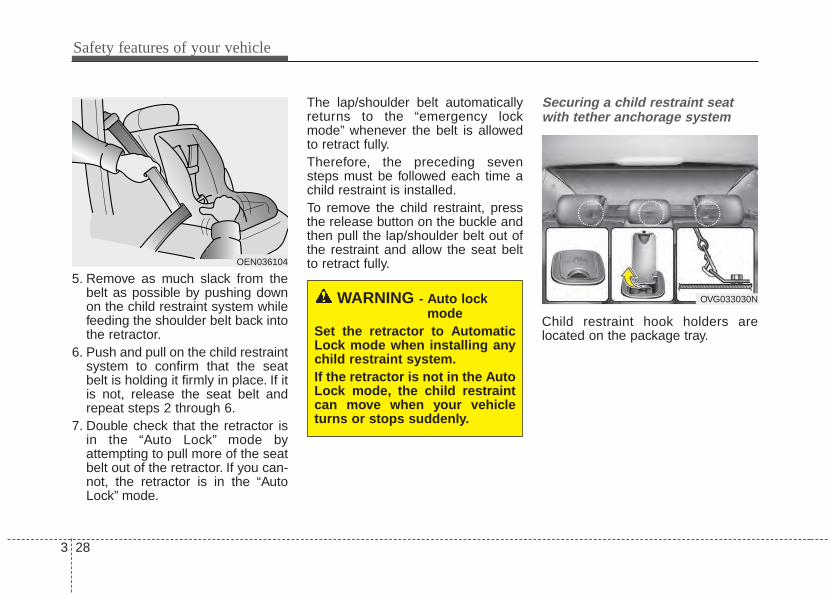
5. Remove as much slack from thebelt as possible by pushing downon the child restraint system whilefeeding the shoulder belt back intothe retractor.
6. Push and pull on the child restraintsystem to confirm that the seatbelt is holding it firmly in place. If itis not, release the seat belt andrepeat steps 2 through 6.
7. Double check that the retractor isin the “Auto Lock” mode byattempting to pull more of the seatbelt out of the retractor. If you can-not, the retractor is in the “AutoLock” mode.
The lap/shoulder belt automaticallyreturns to the “emergency lockmode” whenever the belt is allowedto retract fully.Therefore, the preceding sevensteps must be followed each time achild restraint is installed.To remove the child restraint, pressthe release button on the buckle andthen pull the lap/shoulder belt out ofthe restraint and allow the seat beltto retract fully.
Securing a child restraint seatwith tether anchorage system
Child restraint hook holders arelocated on the package tray.
OEN036104
WARNING - Auto lockmode
Set the retractor to AutomaticLock mode when installing anychild restraint system.If the retractor is not in the AutoLock mode, the child restraintcan move when your vehicleturns or stops suddenly.
OVG033030N
3 29
Safety features of your vehicle
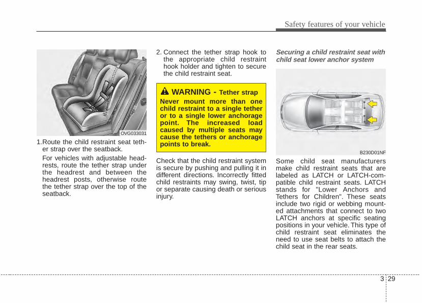
1.Route the child restraint seat teth-er strap over the seatback.For vehicles with adjustable head-rests, route the tether strap underthe headrest and between theheadrest posts, otherwise routethe tether strap over the top of theseatback.
2. Connect the tether strap hook tothe appropriate child restrainthook holder and tighten to securethe child restraint seat.
Check that the child restraint systemis secure by pushing and pulling it indifferent directions. Incorrectly fittedchild restraints may swing, twist, tipor separate causing death or seriousinjury.
Securing a child restraint seat withchild seat lower anchor system
Some child seat manufacturersmake child restraint seats that arelabeled as LATCH or LATCH-com-patible child restraint seats. LATCHstands for "Lower Anchors andTethers for Children". These seatsinclude two rigid or webbing mount-ed attachments that connect to twoLATCH anchors at specific seatingpositions in your vehicle. This type ofchild restraint seat eliminates theneed to use seat belts to attach thechild seat in the rear seats.
WARNING - Tether strapNever mount more than onechild restraint to a single tetheror to a single lower anchoragepoint. The increased loadcaused by multiple seats maycause the tethers or anchoragepoints to break.
B230D01NF
OVG033031
Safety features of your vehicle
303
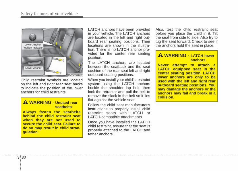
Child restraint symbols are locatedon the left and right rear seat backsto indicate the position of the loweranchors for child restraints.
LATCH anchors have been providedin your vehicle. The LATCH anchorsare located in the left and right out-board rear seating positions. Theirlocations are shown in the illustra-tion. There is no LATCH anchor pro-vided for the center rear seatingposition.The LATCH anchors are locatedbetween the seatback and the seatcushion of the rear seat left and rightoutboard seating positions.When you install your child's restraintsystem using the LATCH anchorsbuckle the shoulder lap belt, thenlock the retractor and pull the belt toremove the slack in the belt so it liesflat against the vehicle seat.Follow the child seat manufacturer’sinstructions to properly install childrestraint seats with LATCH orLATCH-compatible attachments.Once you have installed the LATCHchild restraint, assure that the seat isproperly attached to the LATCH andtether anchors.
Also, test the child restraint seatbefore you place the child in it. Tiltthe seat from side to side. Also try totug the seat forward. Check to see ifthe anchors hold the seat in place.
WARNING - Unused rearseatbelts
Always fasten the seatbeltsbehind the child restraint seatwhen they are not used tosecure the child seat. Failure todo so may result in child stran-gulation.
OVG039032
Lower Anchor
Lower AnchorPosition Indicator
WARNING - LATCH loweranchors
Never attempt to attach aLATCH equipped seat in thecenter seating position. LATCHlower anchors are only to beused with the left and right rearoutboard seating positions. Youmay damage the anchors or theanchors may fail and break in acollision.
3 31
Safety features of your vehicle
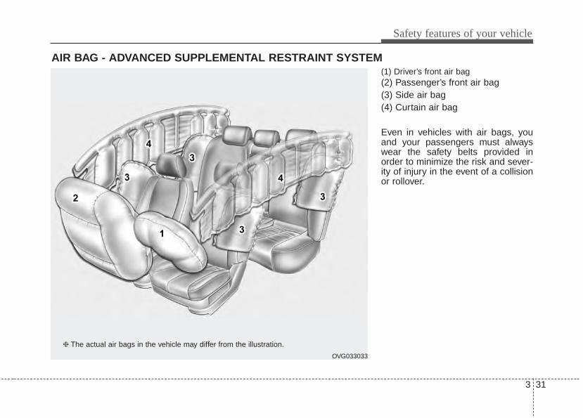
(1) Driver’s front air bag(2) Passenger’s front air bag(3) Side air bag(4) Curtain air bag
Even in vehicles with air bags, youand your passengers must alwayswear the safety belts provided inorder to minimize the risk and sever-ity of injury in the event of a collisionor rollover.
AIR BAG - ADVANCED SUPPLEMENTAL RESTRAINT SYSTEM
OVG033033
❈ The actual air bags in the vehicle may differ from the illustration.
Safety features of your vehicle
323
How does the air bag systemoperate • Air bags are activated (able to
inflate if necessary) only when theignition switch is turned to the ONor START the appropriate position.
• Air bags inflate instantly in theevent of serious frontal or side col-lision (if equipped with side air bagor curtain air bag) in order to helpprotect the occupants from seriousphysical injury.
• There is no single speed at whichthe air bags will inflate.Generally, air bags are designed toinflate based upon the severity of acollision and its direction. Thesetwo factors determine whether thesensors produce an electronicdeployment/ inflation signal.
• Air bag deployment depends on anumber of complex factors includ-ing vehicle speed, angles of impactand the density and stiffness of thevehicles or objects which yourvehicle hits in the collision.Though,factors are not limited to thosementioned above.
• The front air bags will completelyinflate and deflate in an instant.It is virtually impossible for you tosee the air bags inflate during anaccident. It is much more likely thatyou will simply see the deflated airbags hanging out of their storagecompartments after the collision.
• In order to help provide protectionin a severe collision, the air bagsmust inflate rapidly. The speed ofair bag inflation is a consequenceof extremely short time in which acollision occurs and the need toget the air bag between the occu-pant and the vehicle structuresbefore the occupant impacts thosestructures. This speed of inflationreduces the risk of serious or life-threatening injuries in a severe col-lision and is thus a necessary partof air bag design.However, air bag inflation can alsocause injuries which can includefacial abrasions, bruises and bro-ken bones because the inflationspeed also causes the air bags toexpand with a great deal of force.
• There are even circumstancesunder which contact with thesteering wheel air bag can causefatal injuries, especially if theoccupant is positioned exces-sively close to the steeringwheel.
3 33
Safety features of your vehicle
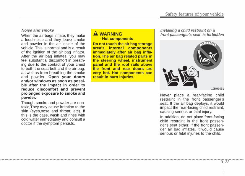
Noise and smokeWhen the air bags inflate, they makea loud noise and they leave smokeand powder in the air inside of thevehicle. This is normal and is a resultof the ignition of the air bag inflator.After the air bag inflates, you mayfeel substantial discomfort in breath-ing due to the contact of your chestto both the seat belt and the air bag,as well as from breathing the smokeand powder. Open your doorsand/or windows as soon as possi-ble after the impact in order toreduce discomfort and preventprolonged exposure to smoke andpowder.Though smoke and powder are non-toxic,They may cause irritation to theskin (eyes,nose and throat, etc). Ifthis is the case, wash and rinse withcold water immediately and consult adoctor if the symptom persists.
Installing a child restraint on afront passenger’s seat is forbidden
Never place a rear-facing childrestraint in the front passenger’sseat. If the air bag deploys, it wouldimpact the rear-facing child restraint,causing serious or fatal injury.In addition, do not place front-facingchild restraint in the front passen-ger’s seat either. If the front passen-ger air bag inflates, it would causeserious or fatal injuries to the child.
1JBH3051
WARNING - Hot components
Do not touch the air bag storagearea's internal componentsimmediately after air bag infla-tion. The air bag related parts inthe steering wheel, instrumentpanel and the roof rails abovethe front and rear doors arevery hot. Hot components canresult in burn injuries.

Safety features of your vehicle
343
Air bag warning light
The purpose of the air bag warninglight in your instrument panel is toalert you of a potential problem withyour air bag - SupplementalRestraint System (SRS).When the ignition switch is turnedON, the indicator light should illumi-nate for approximately 6 seconds,then go off.Have the system checked by anauthorized Kia dealer if:• The light does not turn on briefly
when you turn the ignition ON.• The light stays on after illuminating
for approximately 6 seconds.
• The light comes on while the vehi-cle is in motion.
W7-147
WARNING - Air bagdeployment
When children are seated in therear outboard seats of a vehicleequipped with side and/or cur-tain air bags, install the childrestraint system as far awayfrom the door side as possible.Inflation of the side and/or cur-tain air bags could impact thechild.

3 35
Safety features of your vehicle
SRS components and functions
The SRS consists of the followingcomponents:1. Driver's front air bag module2. Passenger's front air bag module3. Side air bag modules4. Curtain air bag modules5. Retractor pre-tensioner assemblies6. Air bag warning light7. SRS control module (SRSCM)8. Front impact sensors9. Side impact sensors
10. PASSENGER AIR BAG “OFF”indicator (Front passenger’s seatonly)
11. Occupant detection system (Front passenger’s seat only)
12. Driver’s and front passenger’sseat belt buckle sensors
13. Anchor pre-tensioner assembly
The SRSCM continually monitors allSRS components while the ignitionswitch is ON to determine if a crashimpact is severe enough to requireair bag deployment or pre-tensionerseat belt deployment.The SRS air bag warning light on theinstrument panel will illuminate forabout 6 seconds after the ignitionswitch is turned to the ON position,after which the air bag warning lightshould go out.If any of the following conditionsoccurs, this indicates a malfunctionof the SRS. Have an authorized Kiadealer inspect the air bag system assoon as possible.• The light does not turn on briefly
when you turn the ignition ON.
• The light stays on after illuminatingfor approximately 6 seconds.
• The light comes on while the vehi-cle is in motion.
OBH038079L
Safety features of your vehicle
363
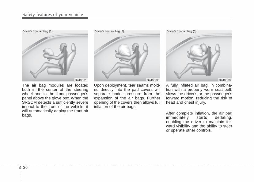
The air bag modules are locatedboth in the center of the steeringwheel and in the front passenger'spanel above the glove box. When theSRSCM detects a sufficiently severeimpact to the front of the vehicle, itwill automatically deploy the front airbags.
Upon deployment, tear seams mold-ed directly into the pad covers willseparate under pressure from theexpansion of the air bags. Furtheropening of the covers then allows fullinflation of the air bags.
A fully inflated air bag, in combina-tion with a properly worn seat belt,slows the driver's or the passenger'sforward motion, reducing the risk ofhead and chest injury.
After complete inflation, the air bagimmediately starts deflating,enabling the driver to maintain for-ward visibility and the ability to steeror operate other controls.
B240B02L
Driver’s front air bag (2)
B240B03L
Driver’s front air bag (3)
B240B01L
Driver’s front air bag (1)
3 37
Safety features of your vehicle
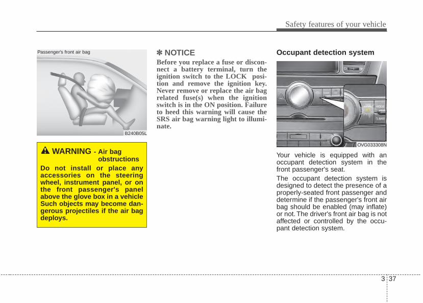
✽✽ NOTICEBefore you replace a fuse or discon-nect a battery terminal, turn theignition switch to the LOCK posi-tion and remove the ignition key.Never remove or replace the air bagrelated fuse(s) when the ignitionswitch is in the ON position. Failureto heed this warning will cause theSRS air bag warning light to illumi-nate.
Occupant detection system
Your vehicle is equipped with anoccupant detection system in thefront passenger's seat.The occupant detection system isdesigned to detect the presence of aproperly-seated front passenger anddetermine if the passenger's front airbag should be enabled (may inflate)or not. The driver's front air bag is notaffected or controlled by the occu-pant detection system.
B240B05L
Passenger’s front air bag
WARNING - Air bagobstructions
Do not install or place anyaccessories on the steeringwheel, instrument panel, or onthe front passenger's panelabove the glove box in a vehicleSuch objects may become dan-gerous projectiles if the air bagdeploys.
OVG033308N
Safety features of your vehicle
383
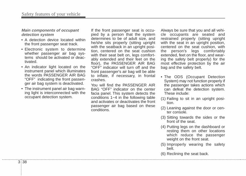
Main components of occupantdetection system• A detection device located within
the front passenger seat track.• Electronic system to determine
whether passenger air bag sys-tems should be activated or deac-tivated.
• An indicator light located on theinstrument panel which illuminatesthe words PASSENGER AIR BAG“OFF” indicating the front passen-ger air bag system is deactivated.
• The instrument panel air bag warn-ing light is interconnected with theoccupant detection system.
If the front passenger seat is occu-pied by a person that the systemdetermines to be of adult size, andhe/she sits properly (sitting uprightwith the seatback in an upright posi-tion, centered on the seat cushionwith their seat belt on, legs comfort-ably extended and their feet on thefloor), the PASSENGER AIR BAG“OFF” indicator will turn off and thefront passenger's air bag will be ableto inflate, if necessary, in frontalcrashes.You will find the PASSENGER AIRBAG “OFF” indicator on the centerfacia panel. This system detects theconditions 1~4 in the following tableand activates or deactivates the frontpassenger air bag based on theseconditions.
Always be sure that you and all vehi-cle occupants are seated andrestrained properly (sitting uprightwith the seat in an upright position,centered on the seat cushion, withthe person’s legs comfortablyextended, feet on the floor, and wear-ing the safety belt properly) for themost effective protection by the airbag and the safety belt.
• The ODS (Occupant DetectionSystem) may not function properly ifthe passenger takes actions whichcan defeat the detection system.These include:
(1) Failing to sit in an upright posi-tion.
(2) Leaning against the door or cen-ter console.
(3) Sitting towards the sides or thefront of the seat.
(4) Putting legs on the dashboard orresting them on other locationswhich reduce the passengerweight on the front seat.
(5) Improperly wearing the safetybelt.
(6) Reclining the seat back.
3 39
Safety features of your vehicle
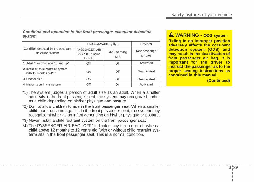
WARNING - ODS systemRiding in an improper positionadversely affects the occupantdetection system (ODS) andmay result in the deactivation offront passenger air bag. It isimportant for the driver toinstruct the passenger as to theproper seating instructions ascontained in this manual.
(Continued)
Condition and operation in the front passenger occupant detectionsystem
*1) The system judges a person of adult size as an adult. When a smalleradult sits in the front passenger seat, the system may recognize him/heras a child depending on his/her physique and posture.
*2) Do not allow children to ride in the front passenger seat. When a smallerchild than the same age sits in the front passenger seat, the system mayrecognize him/her as an infant depending on his/her physique or posture.
*3) Never install a child restraint system on the front passenger seat.*4) The PASSENGER AIR BAG "OFF" indicator may turn on or off when a
child above 12 months to 12 years old (with or without child restraint sys-tem) sits in the front passenger seat. This is a normal condition.
Condition detected by the occupantdetection system
1. Adult *1 or child age 13 and up*2
2. Infant or child restraint system
with 12 months old*3 *4
3. Unoccupied
4. Malfunction in the system
Off
On
On
Off
Off
Off
Off
On
Activated
Deactivated
Deactivated
Activated
PASSENGER AIRBAG “OFF” indica-
tor light
SRS warninglight
Front passengerair bag
Indicator/Warning light Devices
Safety features of your vehicle
403
1KMN3663
1KMN3664
1KMN3665
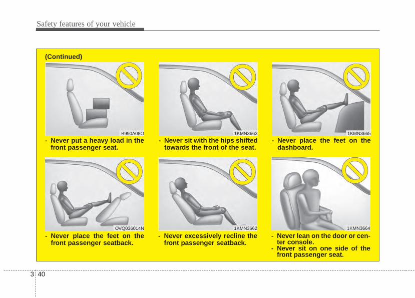
- Never sit with the hips shiftedtowards the front of the seat.
- Never lean on the door or cen-ter console.
- Never sit on one side of thefront passenger seat.
- Never place the feet on thedashboard.
B990A08O
1KMN3662
- Never put a heavy load in thefront passenger seat.
- Never excessively recline thefront passenger seatback.
OVQ036014N
- Never place the feet on thefront passenger seatback.
(Continued)
3 41
Safety features of your vehicle
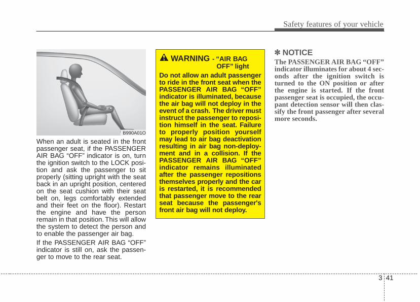
When an adult is seated in the frontpassenger seat, if the PASSENGERAIR BAG “OFF” indicator is on, turnthe ignition switch to the LOCK posi-tion and ask the passenger to sitproperly (sitting upright with the seatback in an upright position, centeredon the seat cushion with their seatbelt on, legs comfortably extendedand their feet on the floor). Restartthe engine and have the personremain in that position. This will allowthe system to detect the person andto enable the passenger air bag.If the PASSENGER AIR BAG “OFF”indicator is still on, ask the passen-ger to move to the rear seat.
✽✽ NOTICEThe PASSENGER AIR BAG “OFF”indicator illuminates for about 4 sec-onds after the ignition switch isturned to the ON position or afterthe engine is started. If the frontpassenger seat is occupied, the occu-pant detection sensor will then clas-sify the front passenger after severalmore seconds.
B990A01O
WARNING - “AIR BAGOFF” light
Do not allow an adult passengerto ride in the front seat when thePASSENGER AIR BAG “OFF”indicator is illuminated, becausethe air bag will not deploy in theevent of a crash. The driver mustinstruct the passenger to reposi-tion himself in the seat. Failureto properly position yourselfmay lead to air bag deactivationresulting in air bag non-deploy-ment and in a collision. If thePASSENGER AIR BAG “OFF”indicator remains illuminatedafter the passenger repositionsthemselves properly and the caris restarted, it is recommendedthat passenger move to the rearseat because the passenger'sfront air bag will not deploy.
Safety features of your vehicle
423
Any child age 12 and under shouldride in the rear seat. Children toolarge for child restraints should usethe available lap/shoulder belts. Nomatter what type of crash, children ofall ages are safer when restrained inthe rear seat.
✽✽ NOTICEDo not modify or replace the frontpassenger seat. Don't place anythingon or attach anything such as a blan-ket, front seat covers or after marketseat heater to the front passengerseat. This can adversely affect theoccupant detection system.
If the occupant detection system isnot working properly, the SRS air bagwarning light on the instrumentpanel will illuminate because the pas-senger's front air bag is connectedwith the occupant detection system. Ifthere is a malfunction of the occupantdetection system, the PASSENGERAIR BAG “OFF” indicator will not illu-minate and the passenger's front airbag will inflate in frontal impact crash-es even if there is no occupant in thefront passenger's seat.
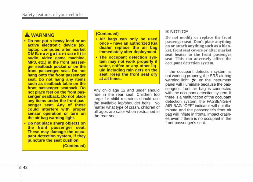
WARNING• Do not put a heavy load or an
active electronic device (ex.laptop computer, after marketDMB/navigat ion/sate l l i teaudio, video game machine,MP3, etc.) in the front passen-ger seatback pocket or on thefront passenger seat. Do nothang onto the front passengerseat. Do not hang any itemssuch as seatback table on thefront passenger seatback. Donot place feet on the front pas-senger seatback. Do not placeany items under the front pas-senger seat. Any of thesecould interfere with propersensor operation or turn onthe air bag warning light.
• Do not place sharp objects onthe front passenger seat.These may damage the occu-pant detection system, if theypuncture the seat cushion.
(Continued)
(Continued)• Air bags can only be used
once – have an authorized Kiadealer replace the air bagimmediately after deployment.
• The occupant detection sys-tem may not work properly ifwater, coffee or any other liq-uid including rain gets on theseat. Keep the front seat dryat all times.
3 43
Safety features of your vehicle
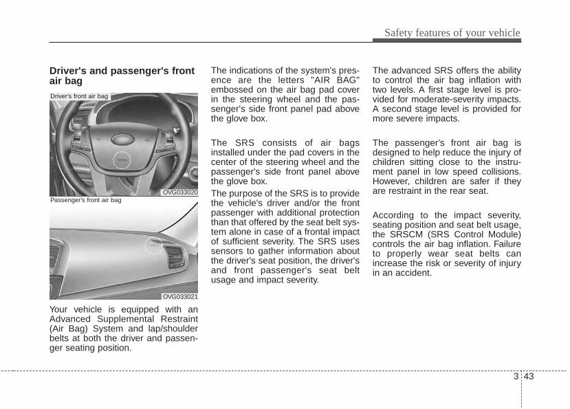
Driver's and passenger's frontair bag
Your vehicle is equipped with anAdvanced Supplemental Restraint(Air Bag) System and lap/shoulderbelts at both the driver and passen-ger seating position.
The indications of the system's pres-ence are the letters "AIR BAG"embossed on the air bag pad coverin the steering wheel and the pas-senger's side front panel pad abovethe glove box.
The SRS consists of air bagsinstalled under the pad covers in thecenter of the steering wheel and thepassenger's side front panel abovethe glove box.The purpose of the SRS is to providethe vehicle's driver and/or the frontpassenger with additional protectionthan that offered by the seat belt sys-tem alone in case of a frontal impactof sufficient severity. The SRS usessensors to gather information aboutthe driver's seat position, the driver'sand front passenger's seat beltusage and impact severity.
The advanced SRS offers the abilityto control the air bag inflation withtwo levels. A first stage level is pro-vided for moderate-severity impacts.A second stage level is provided formore severe impacts.
The passenger’s front air bag isdesigned to help reduce the injury ofchildren sitting close to the instru-ment panel in low speed collisions.However, children are safer if theyare restraint in the rear seat.
According to the impact severity,seating position and seat belt usage,the SRSCM (SRS Control Module)controls the air bag inflation. Failureto properly wear seat belts canincrease the risk or severity of injuryin an accident.
OVG033020
Driver’s front air bag
OVG033021
Passenger’s front air bag
Safety features of your vehicle
443
Additionally, your vehicle is equippedwith an occupant detection system inthe front passenger's seat. The occu-pant detection system detects thepresence of a passenger in the frontpassenger's seat and will turn off thefront passenger's air bag under cer-tain conditions. For more detail, see"Occupant detection system" in thissection.Do not place any objects that maycause magnetic fields near the frontseat.These may cause a malfunctionof the seat track position sensor.
Manufacturers are required by gov-ernment regulations to provide acontact point concerning modifica-tions to the vehicle for persons withdisabilities, which modifications mayaffect the vehicle’s advanced air bagsystem. However, Kia does notendorse nor will it support anychanges to any part or structure ofthe vehicle that could affect theadvanced air bag system, includingthe occupant detection system.
Advanced air bags are combinedwith pre-tensioner seat belts to helpprovide enhanced occupant protec-tion in frontal crashes. Front air bagsare not intended to deploy in colli-sions in which sufficient protectioncan be provided by the pre-tensionerseat belt alone.
Front air bags are not intended todeploy in side-impact, rear-impact orrollover crashes. In addition, front airbags will not deploy in frontal crash-es below the deployment threshold.
WARNING - Replacement/modifications
The front passenger seat, dash-board or door should not bereplaced except by an author-ized Kia dealer using originalKia parts designed for this vehi-cle and model. Any other suchreplacement or modificationcould adversely affect the oper-ation of the occupant detectionsystem and your advanced airbags.
WARNING - SRS WiringDo not tamper with or discon-nect SRS wiring or other com-ponents of the SRS system.Doing so could result in injury,due to accidental deployment ofthe air bags or by rendering theSRS inoperative.
3 45
Safety features of your vehicle
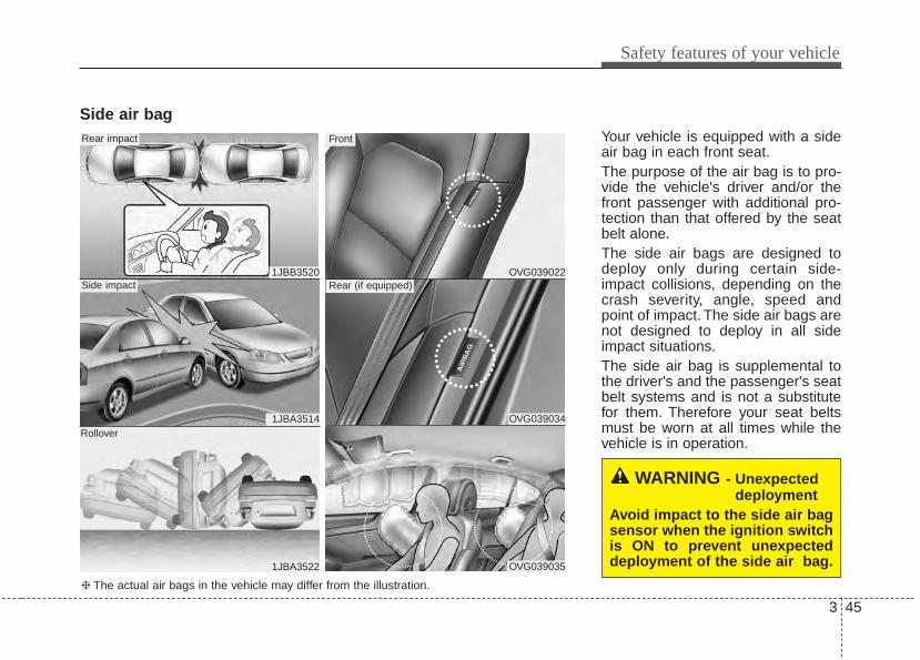
Side air bagYour vehicle is equipped with a sideair bag in each front seat.The purpose of the air bag is to pro-vide the vehicle's driver and/or thefront passenger with additional pro-tection than that offered by the seatbelt alone.The side air bags are designed todeploy only during certain side-impact collisions, depending on thecrash severity, angle, speed andpoint of impact. The side air bags arenot designed to deploy in all sideimpact situations.The side air bag is supplemental tothe driver's and the passenger's seatbelt systems and is not a substitutefor them. Therefore your seat beltsmust be worn at all times while thevehicle is in operation.
WARNING - Unexpecteddeployment
Avoid impact to the side air bagsensor when the ignition switchis ON to prevent unexpecteddeployment of the side air bag.
1JBB3520
1JBA3514
1JBA3522
Side impact
Rear impact
Rollover
OVG039022
OVG039034
OVG039035
Rear (if equipped)
Front
❈ The actual air bags in the vehicle may differ from the illustration.
Safety features of your vehicle
463
For best protection from the side airbag system and to avoid beinginjured by the deploying side air bag,both front seat occupants should sitin an upright position with the seatbelt properly fastened. The driver'shands should be placed on the steer-ing wheel at the 9:00 and 3:00 posi-tions. The passenger's arms andhands should be placed on their laps.
If seat or seat cover is damaged,have the vehicle checked andrepaired by an authorized Kia dealer.Inform that your vehicle is equippedwith side air bags and an occupantdetection system.
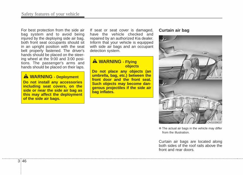
Curtain air bag
❈ The actual air bags in the vehicle may differfrom the illustration.
Curtain air bags are located alongboth sides of the roof rails above thefront and rear doors.
WARNING - DeploymentDo not install any accessoriesincluding seat covers, on theside or near the side air bag asthis may affect the deploymentof the side air bags.
WARNING - Flyingobjects
Do not place any objects (anumbrella, bag, etc.) between thefront door and the front seat.Such objects may become dan-gerous projectiles if the side airbag inflates.
OVG039036
OVG039037
3 47
Safety features of your vehicle
They are designed to help protectthe heads of the front seat occupantsand the rear outboard seat occu-pants in certain side impact colli-sions.The curtain air bags are designed todeploy only during certain sideimpact collisions, depending on thecrash severity, angle, speed andimpact. The curtain air bags are notdesigned to deploy in all side impactsituations, collisions from the front orrear of the vehicle or in most rolloversituations.Do not allow the passengers to leantheir heads or bodies onto doors, puttheir arms on the doors, stretch theirarms out of the window, or placeobjects between the doors and pas-sengers when they are seated onseats equipped with side and/or cur-tain air bags.
✽✽ NOTICENever try to open or repair any com-ponents of the side curtain air bagsystem. This should only be done byan authorized Kia dealer.
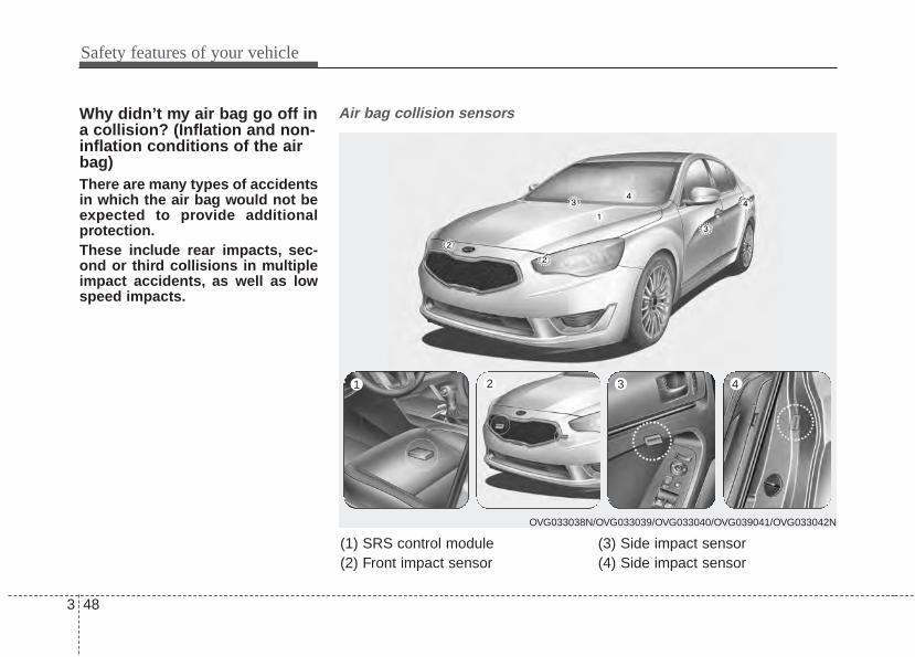
Safety features of your vehicle
483
Why didn’t my air bag go off ina collision? (Inflation and non-inflation conditions of the airbag)There are many types of accidentsin which the air bag would not beexpected to provide additionalprotection.These include rear impacts, sec-ond or third collisions in multipleimpact accidents, as well as lowspeed impacts.
Air bag collision sensors
(1) SRS control module(2) Front impact sensor
(3) Side impact sensor (4) Side impact sensor
OVG033038N/OVG033039/OVG033040/OVG039041/OVG033042N
1 2 3 4
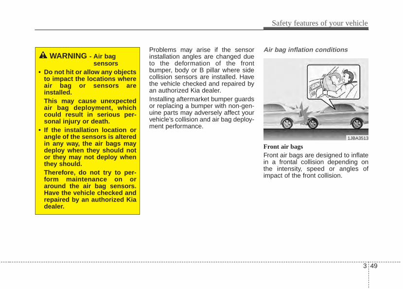
3 49
Safety features of your vehicle
Problems may arise if the sensorinstallation angles are changed dueto the deformation of the frontbumper, body or B pillar where sidecollision sensors are installed. Havethe vehicle checked and repaired byan authorized Kia dealer.Installing aftermarket bumper guardsor replacing a bumper with non-gen-uine parts may adversely affect yourvehicle’s collision and air bag deploy-ment performance.
Air bag inflation conditions
Front air bags Front air bags are designed to inflatein a frontal collision depending onthe intensity, speed or angles ofimpact of the front collision.
WARNING - Air bag sensors
• Do not hit or allow any objectsto impact the locations whereair bag or sensors areinstalled.This may cause unexpectedair bag deployment, whichcould result in serious per-sonal injury or death.
• If the installation location orangle of the sensors is alteredin any way, the air bags maydeploy when they should notor they may not deploy whenthey should.Therefore, do not try to per-form maintenance on oraround the air bag sensors.Have the vehicle checked andrepaired by an authorized Kiadealer.
1JBA3513
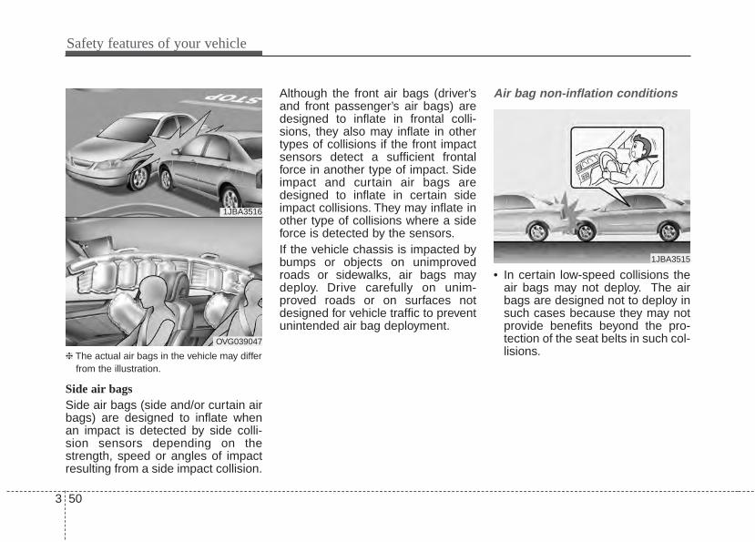
Safety features of your vehicle
503
❈ The actual air bags in the vehicle may differfrom the illustration.
Side air bagsSide air bags (side and/or curtain airbags) are designed to inflate whenan impact is detected by side colli-sion sensors depending on thestrength, speed or angles of impactresulting from a side impact collision.
Although the front air bags (driver’sand front passenger’s air bags) aredesigned to inflate in frontal colli-sions, they also may inflate in othertypes of collisions if the front impactsensors detect a sufficient frontalforce in another type of impact. Sideimpact and curtain air bags aredesigned to inflate in certain sideimpact collisions. They may inflate inother type of collisions where a sideforce is detected by the sensors.If the vehicle chassis is impacted bybumps or objects on unimprovedroads or sidewalks, air bags maydeploy. Drive carefully on unim-proved roads or on surfaces notdesigned for vehicle traffic to preventunintended air bag deployment.
Air bag non-inflation conditions
• In certain low-speed collisions theair bags may not deploy. The airbags are designed not to deploy insuch cases because they may notprovide benefits beyond the pro-tection of the seat belts in such col-lisions.
1JBA3516
OVG039047
1JBA3515
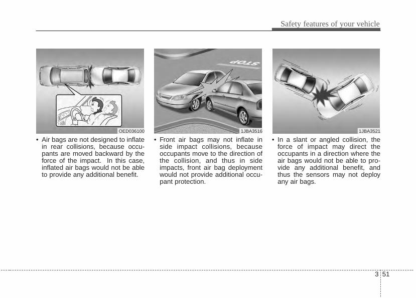
3 51
Safety features of your vehicle
• Air bags are not designed to inflatein rear collisions, because occu-pants are moved backward by theforce of the impact. In this case,inflated air bags would not be ableto provide any additional benefit.
• Front air bags may not inflate inside impact collisions, becauseoccupants move to the direction ofthe collision, and thus in sideimpacts, front air bag deploymentwould not provide additional occu-pant protection.
• In a slant or angled collision, theforce of impact may direct theoccupants in a direction where theair bags would not be able to pro-vide any additional benefit, andthus the sensors may not deployany air bags.
OED036100 1JBA35211JBA3516
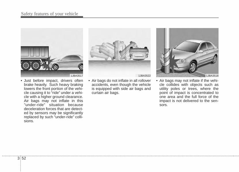
Safety features of your vehicle
523
• Just before impact, drivers oftenbrake heavily. Such heavy brakinglowers the front portion of the vehi-cle causing it to “ride” under a vehi-cle with a higher ground clearance.Air bags may not inflate in this"under-ride" situation becausedeceleration forces that are detect-ed by sensors may be significantlyreplaced by such “under-ride” colli-sions.
• Air bags do not inflate in all rolloveraccidents, even though the vehicleis equipped with side air bags andcurtain air bags.
• Air bags may not inflate if the vehi-cle collides with objects such asutility poles or trees, where thepoint of impact is concentrated toone area and the full force of theimpact is not delivered to the sen-sors.
1JBA3517 1JBA3522 1JBA3518
3 53
Safety features of your vehicle
SRS CareThe SRS is virtually maintenance-freeand there are no parts you can safelyservice by yourself. If the SRS air bagwarning light does not illuminate, orcontinuously remains on, have yourvehicle immediately inspected by anauthorized Kia dealer.
Any work on the SRS system, suchas removing, installing, repairing, orany work on the steering wheel mustbe performed by an authorized Kiadealer. Improper handling of the SRSsystem may result in serious personalinjury.
For cleaning the air bag pad covers,use only a soft, dry cloth or one whichhas been moistened with plain water.Solvents or cleaners could adverselyaffect the air bag covers and properdeployment of the system.
If components of the air bag systemmust be discarded, or if the vehiclemust be scrapped, certain safetyprecautions must be observed. Anauthorized Kia dealer knows theseprecautions and can give you thenecessary information. Failure to fol-low these precautions and proce-dures could increase the risk of per-sonal injury.
Adding equipment to or modi-fying your air bag-equippedvehicleIf you modify your vehicle by chang-ing your vehicle's frame, bumper sys-tem, front end or side sheet metal orride height, this may affect the opera-tion of your vehicle's air bag system.
WARNING - Tamperingwith SRS
Do not tamper with or discon-nect SRS wiring, or other compo-nents of the SRS system. Doingso could result in the accidentalinflation of the air bags or by ren-dering the SRS inoperative.
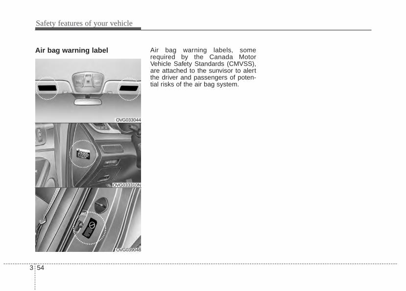
Safety features of your vehicle
543
Air bag warning label Air bag warning labels, somerequired by the Canada MotorVehicle Safety Standards (CMVSS),are attached to the sunvisor to alertthe driver and passengers of poten-tial risks of the air bag system.
OVG033044
OVG039048
OVG033310N
Features of your vehicle
Smart key . . . . . . . . . . . . . . . . . . . . . . . . . . . . . . . . . 4-4• Record your key number . . . . . . . . . . . . . . . . . . . . . . . 4-4• Smart key function . . . . . . . . . . . . . . . . . . . . . . . . . . . . 4-4• Smart key precautions . . . . . . . . . . . . . . . . . . . . . . . . . 4-5• Remote keyless entry system operations. . . . . . . . . . . 4-6• Transmitter precautions . . . . . . . . . . . . . . . . . . . . . . . . 4-7• Battery replacement . . . . . . . . . . . . . . . . . . . . . . . . . . . 4-8• Immobilizer system . . . . . . . . . . . . . . . . . . . . . . . . . . . 4-11
Theft-alarm system . . . . . . . . . . . . . . . . . . . . . . . . 4-14• Armed stage . . . . . . . . . . . . . . . . . . . . . . . . . . . . . . . . . 4-14• Theft-alarm stage . . . . . . . . . . . . . . . . . . . . . . . . . . . . 4-15• Disarmed stage. . . . . . . . . . . . . . . . . . . . . . . . . . . . . . . 4-15
Door locks . . . . . . . . . . . . . . . . . . . . . . . . . . . . . . . 4-17• Operatiom (from outside). . . . . . . . . . . . . . . . . . . . . . 4-17• Operatiom (from inside) . . . . . . . . . . . . . . . . . . . . . . . 4-18• Impact sensing door unlock system. . . . . . . . . . . . . . 4-20• Auto door lock/unlock feature . . . . . . . . . . . . . . . . . . 4-20• Child-protector rear door lock . . . . . . . . . . . . . . . . . 4-20
Trunk . . . . . . . . . . . . . . . . . . . . . . . . . . . . . . . . . . . 4-21• Opening . . . . . . . . . . . . . . . . . . . . . . . . . . . . . . . . . . . . 4-21• Closing . . . . . . . . . . . . . . . . . . . . . . . . . . . . . . . . . . . . . 4-22• Emergency trunk safety release. . . . . . . . . . . . . . . . . 4-22
Windows . . . . . . . . . . . . . . . . . . . . . . . . . . . . . . . . . 4-23• Power windows . . . . . . . . . . . . . . . . . . . . . . . . . . . . . . 4-24
Hood. . . . . . . . . . . . . . . . . . . . . . . . . . . . . . . . . . . . . 4-27• Opening . . . . . . . . . . . . . . . . . . . . . . . . . . . . . . . . . . . . 4-27• Closing . . . . . . . . . . . . . . . . . . . . . . . . . . . . . . . . . . . . . 4-28
Fuel filler lid . . . . . . . . . . . . . . . . . . . . . . . . . . . . . . 4-29• Opening and closing . . . . . . . . . . . . . . . . . . . . . . . . . . 4-29• Emergency fuel filler lid release. . . . . . . . . . . . . . . . . 4-31
Panoramic sunroof . . . . . . . . . . . . . . . . . . . . . . . . . 4-32• Sunroof open warning . . . . . . . . . . . . . . . . . . . . . . . . 4-32• Sliding the sunroof . . . . . . . . . . . . . . . . . . . . . . . . . . . 4-33• Closing the sunroof . . . . . . . . . . . . . . . . . . . . . . . . . . . 4-33• Tilting the sunroof . . . . . . . . . . . . . . . . . . . . . . . . . . . . 4-34• Sunshade . . . . . . . . . . . . . . . . . . . . . . . . . . . . . . . . . . . 4-35• Resetting the sunroof . . . . . . . . . . . . . . . . . . . . . . . . . 4-36
Steering wheel. . . . . . . . . . . . . . . . . . . . . . . . . . . . . 4-37• Electric power steering (EPS) . . . . . . . . . . . . . . . . . . 4-37• Tilt and telescopic steering . . . . . . . . . . . . . . . . . . . . . 4-38• Heated steering wheel . . . . . . . . . . . . . . . . . . . . . . . . 4-39• Horn . . . . . . . . . . . . . . . . . . . . . . . . . . . . . . . . . . . . . . . 4-39
Mirrors . . . . . . . . . . . . . . . . . . . . . . . . . . . . . . . . . . 4-40• Inside rearview mirror . . . . . . . . . . . . . . . . . . . . . . . . 4-40• Outside rearview mirror . . . . . . . . . . . . . . . . . . . . . . 4-48
Instrument cluster . . . . . . . . . . . . . . . . . . . . . . . . . 4-52• Instrument Cluster Control . . . . . . . . . . . . . . . . . . . . 4-53• LCD Display Control . . . . . . . . . . . . . . . . . . . . . . . . . 4-53• Gauges . . . . . . . . . . . . . . . . . . . . . . . . . . . . . . . . . . . . . 4-54
4
• Transaxle Shift Indicator . . . . . . . . . . . . . . . . . . . . . . 4-58LCD display . . . . . . . . . . . . . . . . . . . . . . . . . . . . . . 4-59
• LCD Modes . . . . . . . . . . . . . . . . . . . . . . . . . . . . . . . . . 4-59• Service Mode . . . . . . . . . . . . . . . . . . . . . . . . . . . . . . . . 4-60• User Settings Mode . . . . . . . . . . . . . . . . . . . . . . . . . . . 4-62• A/V Mode . . . . . . . . . . . . . . . . . . . . . . . . . . . . . . . . . . . 4-65• Turn By Turn Mode. . . . . . . . . . . . . . . . . . . . . . . . . . . 4-65• Warning Messages . . . . . . . . . . . . . . . . . . . . . . . . . . . . 4-66
Trip computer. . . . . . . . . . . . . . . . . . . . . . . . . . . . . 4-73• Overview. . . . . . . . . . . . . . . . . . . . . . . . . . . . . . . . . . . . 4-73• Fuel Economy . . . . . . . . . . . . . . . . . . . . . . . . . . . . . . . 4-73• Trip A/B . . . . . . . . . . . . . . . . . . . . . . . . . . . . . . . . . . . . 4-75
Warning and indicator lights . . . . . . . . . . . . . . . . 4-77• Warning lights . . . . . . . . . . . . . . . . . . . . . . . . . . . . . . . 4-77• Indicator Lights . . . . . . . . . . . . . . . . . . . . . . . . . . . . . . 4-86
Rear parking assist system . . . . . . . . . . . . . . . . . . 4-90• Operation . . . . . . . . . . . . . . . . . . . . . . . . . . . . . . . . . . . 4-90• Non-operational conditions . . . . . . . . . . . . . . . . . . . . 4-91• Precautions. . . . . . . . . . . . . . . . . . . . . . . . . . . . . . . . . . 4-92• Self-diagnosis . . . . . . . . . . . . . . . . . . . . . . . . . . . . . . . . 4-93
Rearview camera . . . . . . . . . . . . . . . . . . . . . . . . . . 4-94Welcome system . . . . . . . . . . . . . . . . . . . . . . . . . . . 4-95
• Welcome light. . . . . . . . . . . . . . . . . . . . . . . . . . . . . . . . 4-95• Interior light . . . . . . . . . . . . . . . . . . . . . . . . . . . . . . . . 4-95
Harzard warning flasher . . . . . . . . . . . . . . . . . . . . 4-96Lighting . . . . . . . . . . . . . . . . . . . . . . . . . . . . . . . . . . 4-97
• Battery saver function. . . . . . . . . . . . . . . . . . . . . . . . . 4-97• Headlight escort function . . . . . . . . . . . . . . . . . . . . . . 4-97• Daytime running light. . . . . . . . . . . . . . . . . . . . . . . . . 4-97• Lighting control . . . . . . . . . . . . . . . . . . . . . . . . . . . . . . 4-98• High beam operation . . . . . . . . . . . . . . . . . . . . . . . . 4-100• Turn signals and lane change signals . . . . . . . . . . . 4-101• Front fog light . . . . . . . . . . . . . . . . . . . . . . . . . . . . . . 4-102• Headlight leveling device . . . . . . . . . . . . . . . . . . . . . 4-103
Wiper and washers. . . . . . . . . . . . . . . . . . . . . . . . 4-104• Windshield wiper and washer . . . . . . . . . . . . . . . . . 4-104
Interior light . . . . . . . . . . . . . . . . . . . . . . . . . . . . . 4-107• Automatic turn off function . . . . . . . . . . . . . . . . . . . 4-107• Map lamp . . . . . . . . . . . . . . . . . . . . . . . . . . . . . . . . . 4-107• Room lamp. . . . . . . . . . . . . . . . . . . . . . . . . . . . . . . . . 4-108• Map lamp/Room lamp/Mood lamp . . . . . . . . . . . . . 4-109• Trunk room lamp . . . . . . . . . . . . . . . . . . . . . . . . . . . 4-110• Door courtesy lamp. . . . . . . . . . . . . . . . . . . . . . . . . . 4-110• Glove box lamp . . . . . . . . . . . . . . . . . . . . . . . . . . . . . 4-110• Vanity mirror lamp . . . . . . . . . . . . . . . . . . . . . . . . . . 4-111
Defroster . . . . . . . . . . . . . . . . . . . . . . . . . . . . . . . . 4-112• Rear window defroster . . . . . . . . . . . . . . . . . . . . . . . 4-112• Wiper deicer . . . . . . . . . . . . . . . . . . . . . . . . . . . . . . . 4-112
4
Automaticl climate control system . . . . . . . . . . . 4-113• Heating and air conditioning . . . . . . . . . . . . . . . . . . 4-114• Manual heating and air conditioning . . . . . . . . . . . 4-116• System operation . . . . . . . . . . . . . . . . . . . . . . . . . . . . 4-122• Climate control air filter. . . . . . . . . . . . . . . . . . . . . . 4-124• Air conditioner refrigerant and compressor
lubricant . . . . . . . . . . . . . . . . . . . . . . . . . . . . . . . . . 4-125Windshield defrosting and defogging. . . . . . . . . 4-126
• To defog inside windshield . . . . . . . . . . . . . . . . . . . . 4-126• To defrost outside windshield . . . . . . . . . . . . . . . . . 4-127• Defogging logic. . . . . . . . . . . . . . . . . . . . . . . . . . . . . . 4-127
Storage compartment. . . . . . . . . . . . . . . . . . . . . . 4-130• Center console storage . . . . . . . . . . . . . . . . . . . . . . . 4-130• Glove box . . . . . . . . . . . . . . . . . . . . . . . . . . . . . . . . . . 4-130• Sunglass holder. . . . . . . . . . . . . . . . . . . . . . . . . . . . . 4-131
Interior features . . . . . . . . . . . . . . . . . . . . . . . . . . 4-132• Cup holder . . . . . . . . . . . . . . . . . . . . . . . . . . . . . . . . . 4-132• Sunvisor . . . . . . . . . . . . . . . . . . . . . . . . . . . . . . . . . . . 4-132• Seat warmer . . . . . . . . . . . . . . . . . . . . . . . . . . . . . . . . 4-133• Air ventilation seat . . . . . . . . . . . . . . . . . . . . . . . . . . 4-134• Power outlet . . . . . . . . . . . . . . . . . . . . . . . . . . . . . . . . 4-135• Clock. . . . . . . . . . . . . . . . . . . . . . . . . . . . . . . . . . . . . . 4-136• Clothes hanger . . . . . . . . . . . . . . . . . . . . . . . . . . . . . . 4-137• Floor mat anchor. . . . . . . . . . . . . . . . . . . . . . . . . . . . 4-137• Luggage net holder . . . . . . . . . . . . . . . . . . . . . . . . . . 4-138
• Rear curtain . . . . . . . . . . . . . . . . . . . . . . . . . . . . . . . . 4-139• Navigation system . . . . . . . . . . . . . . . . . . . . . . . . . . . 4-139
Audio system. . . . . . . . . . . . . . . . . . . . . . . . . . . . . 4-140• Antenna . . . . . . . . . . . . . . . . . . . . . . . . . . . . . . . . . . . 4-140• Steering wheel remote controller . . . . . . . . . . . . . . . 4-141• Aux, USB port . . . . . . . . . . . . . . . . . . . . . . . . . . . . . . 4-142
4
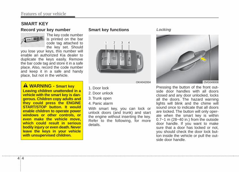
Features of your vehicle
44
Record your key numberThe key code numberis printed on the barcode tag attached tothe key set. Should
you lose your keys, this number willenable an authorized Kia dealer toduplicate the keys easily. Removethe bar code tag and store it in a safeplace. Also, record the code numberand keep it in a safe and handyplace, but not in the vehicle.
Smart key functions
1. Door lock2. Door unlock3. Trunk open4. Panic alarmWith smart key, you can lock orunlock doors (and trunk) and startthe engine without inserting the key.Refer to the following, for moredetails.
Locking
Pressing the button of the front out-side door handles with all doorsclosed and any door unlocked, locksall the doors. The hazard warninglights will blink and the chime willsound once to indicate that all doorsare locked. The button will only oper-ate when the smart key is within0.7~1 m (28~40 in.) from the outsidedoor handle. If you want to makesure that a door has locked or not,you should check the door lock but-ton inside the vehicle or pull the out-side door handle.
SMART KEY
WARNING - Smart keyLeaving children unattended in avehicle with the smart key is dan-gerous. Children copy adults andthey could press the ENGINESTART/STOP button. It wouldenable children to operate powerwindows or other controls, oreven make the vehicle move,which could result in seriousbodily injury or even death. Neverleave the keys in your vehiclewith unsupervised children.
OKH042004 OVG049008
4 5
Features of your vehicle
In some instances, when the outsidedoor button is selected, the doors willnot lock and an audible chime willsound for 3 seconds if any of the fol-lowing occurs:• The smart key is in the vehicle.• The ignition switch is in the ACC or
ON position.• Any door except the trunk is
opened.
Unlocking Pressing the button of the driver's (orfront passenger’s) outside door han-dle with all doors closed and locked,unlocks the driver's door.If you press the button of the driver'soutside door handle again within 4seconds, The other doors will beunlocked. But if you press the buttonof the driver's outside door handleagain after 4 seconds, all doors will belocked. The hazard warning lights willblink and the chime will sound twice toindicate that the driver's door isunlocked. Also, the outside rearviewmirrors will automatically unfold if theoutside rearview mirror folding switchis in the AUTO position.The button will only operate when thesmart key is within 0.7~1 m (28~40in.) from the outside door handle.
Start-upYou can start the engine withoutinserting the key. For detailed infor-mation refer to “Starting the enginewith a smart key” in chapter 5.
Smart key precautions• If you lose your smart key, you will
not be able to start the engine. Towthe vehicle, if necessary, and con-tact an authorized Kia dealer.
• A maximum of 3 smart keys can beregistered to a single vehicle. If youlose a smart key, you should imme-diately take the vehicle and key toyour authorized Kia dealer to pro-tect it from potential theft.
• The smart key will not work if anyof following occurs:- The smart key is close to a radio
transmitter such as a radio sta-tion or an airport which can inter-fere with normal operation of thesmart key.
- The smart key near a mobile two-way radio system or a cellularphone.
- Another vehicle’s smart key isbeing operated close to yourvehicle.
When the smart key does not workcorrectly, open and close the doorwith the mechanical key. If youhave a problem with the smart key,contact an authorized Kia dealer.
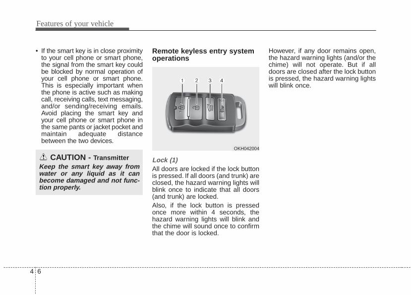
Features of your vehicle
64
• If the smart key is in close proximityto your cell phone or smart phone,the signal from the smart key couldbe blocked by normal operation ofyour cell phone or smart phone.This is especially important whenthe phone is active such as makingcall, receiving calls, text messaging,and/or sending/receiving emails.Avoid placing the smart key andyour cell phone or smart phone inthe same pants or jacket pocket andmaintain adequate distancebetween the two devices.
Remote keyless entry systemoperations
Lock (1)All doors are locked if the lock buttonis pressed. If all doors (and trunk) areclosed, the hazard warning lights willblink once to indicate that all doors(and trunk) are locked.Also, if the lock button is pressedonce more within 4 seconds, thehazard warning lights will blink andthe chime will sound once to confirmthat the door is locked.
However, if any door remains open,the hazard warning lights (and/or thechime) will not operate. But if alldoors are closed after the lock buttonis pressed, the hazard warning lightswill blink once.
CAUTION - TransmitterKeep the smart key away fromwater or any liquid as it canbecome damaged and not func-tion properly.
OKH042004

4 7
Features of your vehicle
Unlock (2) The driver's door is unlocked if theunlock button is pressed once. Thehazard warning lights will blink (forsmart key, the chime also sounds)twice to indicate that the driver's dooris unlocked.All doors are unlocked if the unlockbutton is pressed once more within 4seconds. The hazard warning lightswill blink (for smart key, the chimealso sounds) twice again to indicatethat all doors are unlocked. Afterpressing this button, the doors willlock automatically unless you openany door within 30 seconds.
✽✽ NOTICEIf the keyless entry system is inoper-ative due to exposure to water or liq-uids, it will not be covered by yourmanufacturer's vehicle warranty.
Trunk open (3)The trunk is opened if the button ispressed for more than 1 second.Once the trunk is opened and thenclosed, the trunk will lock automati-cally.
Panic alarm (4)The horn sounds and the hazardwarning lights blink for about 30 sec-onds if this button is pressed formore than 0.5 seconds. To stop thehorn and lights, press any button onthe transmitter.
Transmitter precautionsThe transmitter (or smart key) will notwork if any of following occurs:• You exceed the operating distance
limit (about 30 m [90 feet]).• The battery in the transmitter (or
smart key) is weak.• Other vehicles or objects may be
blocking the signal.• The weather is extremely cold.• The transmitter (or smart key) is
close to a radio transmitter such asa radio station or an airport whichcan interfere with normal operationof the transmitter.
When the transmitter (or smart key)does not work properly, open andclose the door with the ignition key. Ifyou have a problem with the trans-mitter (or smart key), contact anauthorized Kia dealer.
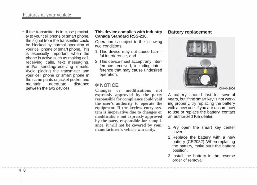
Features of your vehicle
84
• If the transmitter is in close proximi-ty to your cell phone or smart phone,the signal from the transmitter couldbe blocked by normal operation ofyour cell phone or smart phone.Thisis especially important when thephone is active such as making call,receiving calls, text messaging,and/or sending/receiving emails.Avoid placing the transmitter andyour cell phone or smart phone inthe same pants or jacket pocket andmaintain adequate distancebetween the two devices.
This device complies with IndustryCanada Standard RSS-210.Operation is subject to the followingtwo conditions:1. This device may not cause harm-
ful interference, and 2. This device must accept any inter-
ference received, including inter-ference that may cause undesiredoperation.
✽✽ NOTICEChanges or modifications notexpressly approved by the partyresponsible for compliance could voidthe user’s authority to operate theequipment. If the keyless entry sys-tem is inoperative due to changes ormodifications not expressly approvedby the party responsible for compli-ance, it will not be covered by yourmanufacturer’s vehicle warranty.
Battery replacement
A battery should last for severalyears, but if the smart key is not work-ing properly, try replacing the batterywith a new one. If you are unsure howto use or replace the battery, contactan authorized Kia dealer.
1. Pry open the smart key centercover.
2. Replace the battery with a newbattery (CR2032). When replacingthe battery, make sure the batteryposition.
3. Install the battery in the reverseorder of removal.
OKH042006

4 9
Features of your vehicle
The smart key is designed to give youyears of trouble-free use, however itcan malfunction if exposed to mois-ture or static electricity. If you areunsure how to use or replace the bat-tery, contact an authorized Kia dealer.Using the wrong battery can causethe transmitter or smart key to mal-function. Be sure to use the correctbattery.An inappropriately disposed batterycan be harmful to the environmentand human health.Dispose the battery according toyour local law(s) or regulation.
Mechanical key operations• Used to lock and unlock the glove
box.• Lock and unlock the doors when
the vehicle or smart key battery isdischarged.
CAUTION - Transmitterdamage
Do not drop, wet or expose thekeyless entry system transmit-ter to heat or sunlight.
IC WARNINGThis device complies withIndustry Canada licence-exempt RSS standard(s).Operation is subject to the fol-lowing two conditions: (1) thisdevice may not cause interfer-ence, and (2) this device mustaccept any interference, includ-ing interference that may causeundesired operation of thedevice.
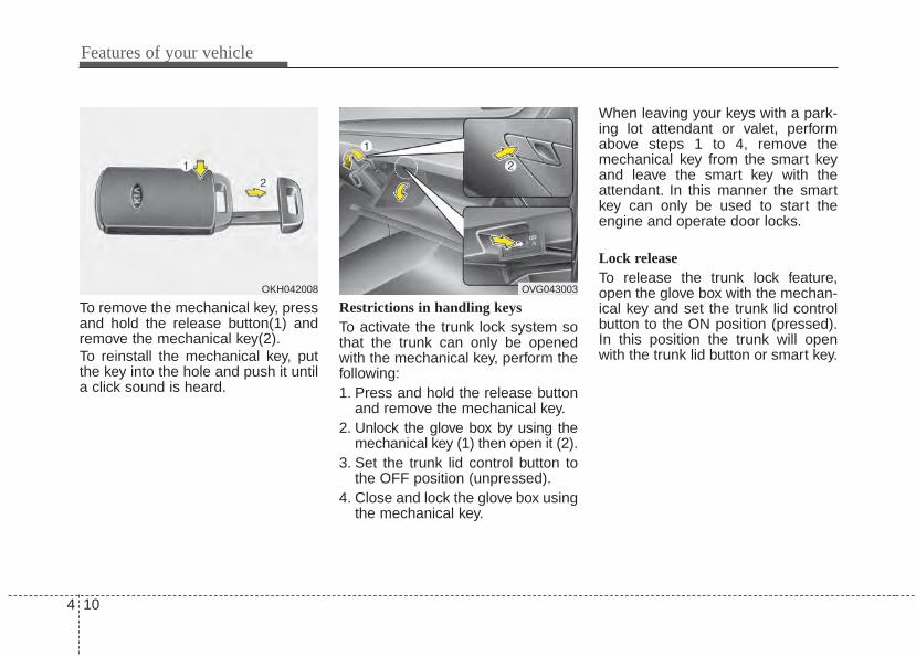
Features of your vehicle
104
To remove the mechanical key, pressand hold the release button(1) andremove the mechanical key(2).To reinstall the mechanical key, putthe key into the hole and push it untila click sound is heard.
Restrictions in handling keysTo activate the trunk lock system sothat the trunk can only be openedwith the mechanical key, perform thefollowing:1. Press and hold the release button
and remove the mechanical key.2. Unlock the glove box by using the
mechanical key (1) then open it (2).3. Set the trunk lid control button to
the OFF position (unpressed).4. Close and lock the glove box using
the mechanical key.
When leaving your keys with a park-ing lot attendant or valet, performabove steps 1 to 4, remove themechanical key from the smart keyand leave the smart key with theattendant. In this manner the smartkey can only be used to start theengine and operate door locks.
Lock releaseTo release the trunk lock feature,open the glove box with the mechan-ical key and set the trunk lid controlbutton to the ON position (pressed).In this position the trunk will openwith the trunk lid button or smart key.
OKH042008 OVG043003
4 11
Features of your vehicle
Immobilizer systemYour vehicle is equipped with anelectronic engine immobilizer systemto reduce the risk of unauthorizedvehicle use.
Whenever the ENGINE START/STOPbutton is changed to the ON position,the immobilizer system checks andverifies if the key is valid or not.If the key is valid, the engine will start.If the key is invalid, the engine willnot start.
To deactivate the immobilizersystemChange the ENGINE START/STOPbutton to the ON position.
To activate the immobilizer systemChange the ENGINE START/STOPbutton to the OFF position.The immo-bilizer system activates automatically.Without a valid smart key for yourvehicle, the engine will not start.
Your immobilizer password is a cus-tomer unique password and shouldbe kept confidential. Do not leave thisnumber anywhere in your vehicle.
✽✽ NOTICEKeep each key separate in order toavoid a starting malfunction.
Do not put metal accessories nearthe ignition switch.Metal accessories may interrupt thetransponder signal and may preventthe engine from being started.If you need additional keys or loseyour keys, consult an authorized Kiadealer.

Features of your vehicle
124
This device complies with IndustryCanada Standard RSS-210.Operation is subject to the followingtwo conditions:1. This device may not cause harm-
ful interference, and 2. This device must accept any inter-
ference received, including inter-ference that may cause undesiredoperation.
Limp home (override) proce-dureWhen you turn the ignition switch tothe ON position, if the immobilizerindicator ( ) goes off after blink-ing 5 times, your transponderequipped in the ignition key is out oforder. You cannot start the enginewithout the limp home procedure. Tostart the engine, you have to inputyour password by using the ignitionswitch. Your password is only avail-able from an authorized Kia dealer-ship. Contact an authorized dealerfor more information.The following procedure is how toinput your password of “2345” as anexample.1. Turn the ignition switch to the ON
position. The immobilizer indicator( ) will blink 5 times and go offindicating the beginning of the limphome procedure.
2. Turn the ignition switch to the ACCposition.
CAUTIONChanges or modifications notexpressly approved by the partyresponsible for compliancecould void the user's authorityto operate the equipment.
CAUTION - Immobilizerdamage
Do not expose your immobilizersystem to moisture, static elec-tricity and rough handling. Thismay damage your immobilizer.
CAUTION - Immobilizeralterations
Do not change, alter or adjustthe immobilizer system becauseit could cause the immobilizersystem to malfunction.
4 13
Features of your vehicle
3. To enter the first digit (in thisexample “2”), turn the ignitionswitch to the ON and ACC positiontwice. Perform the same proce-dure for the next digits between 3seconds and 10 seconds (forexample, for “3”, turn the ignitionON and ACC 3 times).
4. If all of the digits have been inputsuccessfully, you have to start theengine within 30 seconds. If youattempt to start the engine after 30seconds, the engine will not startand you will have to input yourpassword again.
After performing the limp home pro-cedure, you have to see an author-ized Kia dealer immediately toinspect and repair your ignition keyor immobilizer system.
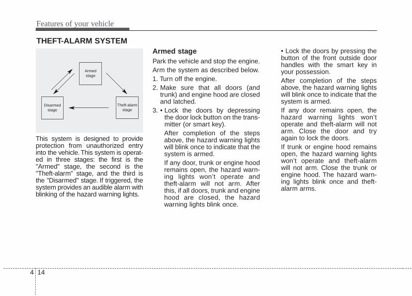
Features of your vehicle
144
THEFT-ALARM SYSTEM
This system is designed to provideprotection from unauthorized entryinto the vehicle. This system is operat-ed in three stages: the first is the"Armed" stage, the second is the"Theft-alarm" stage, and the third isthe "Disarmed" stage. If triggered, thesystem provides an audible alarm withblinking of the hazard warning lights.
Armed stagePark the vehicle and stop the engine.Arm the system as described below.1. Turn off the engine.2. Make sure that all doors (and
trunk) and engine hood are closedand latched.
3. • Lock the doors by depressingthe door lock button on the trans-mitter (or smart key).After completion of the stepsabove, the hazard warning lightswill blink once to indicate that thesystem is armed.If any door, trunk or engine hoodremains open, the hazard warn-ing lights won’t operate andtheft-alarm will not arm. Afterthis, if all doors, trunk and enginehood are closed, the hazardwarning lights blink once.
• Lock the doors by pressing thebutton of the front outside doorhandles with the smart key inyour possession.After completion of the stepsabove, the hazard warning lightswill blink once to indicate that thesystem is armed.If any door remains open, thehazard warning lights won’toperate and theft-alarm will notarm. Close the door and tryagain to lock the doors.If trunk or engine hood remainsopen, the hazard warning lightswon’t operate and theft-alarmwill not arm. Close the trunk orengine hood. The hazard warn-ing lights blink once and theft-alarm arms.
Armedstage
Theft-alarmstage
Disarmedstage
4 15
Features of your vehicle
The theft-alarm system by the keycan be activated by an authorizedKia dealer.If you want this feature, consult anauthorized Kia dealer.
Do not arm the system until allpassengers have left the vehicle. Ifthe system is armed while a pas-senger(s) remains in the vehicle,the alarm may be activated whenthe remaining passenger(s)leaves the vehicle. If any door (ortrunk) or engine hood is openedwithin 30 seconds after the sys-tem enters the armed stage, thesystem will be disarmed to pre-vent unnecessary alarm.
Theft-alarm stageThe alarm will be activated if any ofthe following occurs while the systemis armed.• A front or rear door is opened with-
out using the smart key (ormechanical key).
• The trunk is opened without usingthe smart key (or mechanical key).
• The engine hood is opened.The horn will sound and the hazardwarning lights will blink continuouslyfor approximately 27 seconds. Toturn off the system, unlock the doorswith the smart key.
Disarmed stageThe system will be disarmed when:
Transmitter- The door unlock button is pressed.- The engine is started. (within 3
seconds)- The ignition switch is in the “ON”
position for 30 seconds or more.
Smart key- The door unlock button is pressed.- The button of the front outside door
is pressed while carrying the smartkey.
- The engine is started. (within 3seconds)
After the doors are unlocked, the haz-ard warning lights will blink twice toindicate that the system is disarmed.After pressing the unlock button, if anydoor (or trunk) is not opened within 30seconds, the system will be rearmed.
Features of your vehicle
164
• Avoid trying to start the enginewhile the alarm is activated. Thevehicle starting motor is disabledduring the theft-alarm stage.If the system is not disarmed withthe transmitter, insert the key intothe ignition switch, turn the ignitionswitch to the ON position and waitfor 30 seconds. Then the systemwill be disarmed.
• If you lose your keys, consult yourauthorized Kia dealer.
• If the system is not disarmed withthe transmitter, insert the key intothe ignition switch and start theengine. Then the system will bedisarmed.
• If you lose your keys, consult yourauthorized Kia dealer.
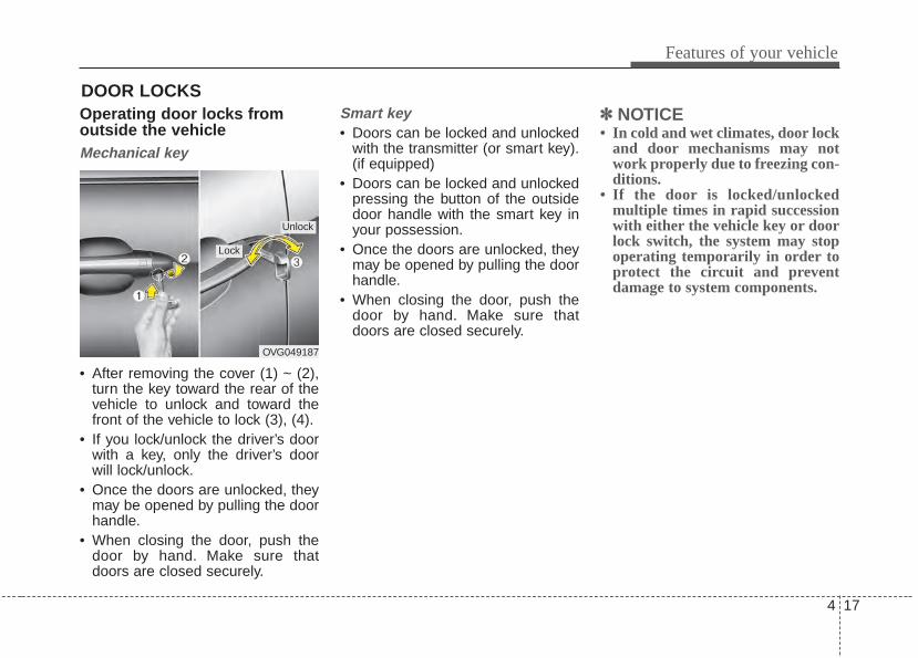
4 17
Features of your vehicle
DOOR LOCKSOperating door locks fromoutside the vehicle Mechanical key
• After removing the cover (1) ~ (2),turn the key toward the rear of thevehicle to unlock and toward thefront of the vehicle to lock (3), (4).
• If you lock/unlock the driver’s doorwith a key, only the driver’s doorwill lock/unlock.
• Once the doors are unlocked, theymay be opened by pulling the doorhandle.
• When closing the door, push thedoor by hand. Make sure thatdoors are closed securely.
Smart key• Doors can be locked and unlocked
with the transmitter (or smart key).(if equipped)
• Doors can be locked and unlockedpressing the button of the outsidedoor handle with the smart key inyour possession.
• Once the doors are unlocked, theymay be opened by pulling the doorhandle.
• When closing the door, push thedoor by hand. Make sure thatdoors are closed securely.
✽✽ NOTICE• In cold and wet climates, door lock
and door mechanisms may notwork properly due to freezing con-ditions.
• If the door is locked/unlockedmultiple times in rapid successionwith either the vehicle key or doorlock switch, the system may stopoperating temporarily in order toprotect the circuit and preventdamage to system components.
OVG049187
Lock
Unlock
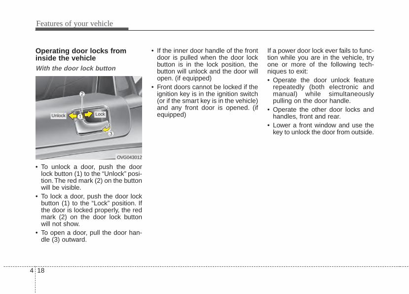
Features of your vehicle
184
Operating door locks frominside the vehicleWith the door lock button
• To unlock a door, push the doorlock button (1) to the “Unlock” posi-tion.The red mark (2) on the buttonwill be visible.
• To lock a door, push the door lockbutton (1) to the “Lock” position. Ifthe door is locked properly, the redmark (2) on the door lock buttonwill not show.
• To open a door, pull the door han-dle (3) outward.
• If the inner door handle of the frontdoor is pulled when the door lockbutton is in the lock position, thebutton will unlock and the door willopen. (if equipped)
• Front doors cannot be locked if theignition key is in the ignition switch(or if the smart key is in the vehicle)and any front door is opened. (ifequipped)
If a power door lock ever fails to func-tion while you are in the vehicle, tryone or more of the following tech-niques to exit:• Operate the door unlock feature
repeatedly (both electronic andmanual) while simultaneouslypulling on the door handle.
• Operate the other door locks andhandles, front and rear.
• Lower a front window and use thekey to unlock the door from outside.
OVG043012
Lock Unlock
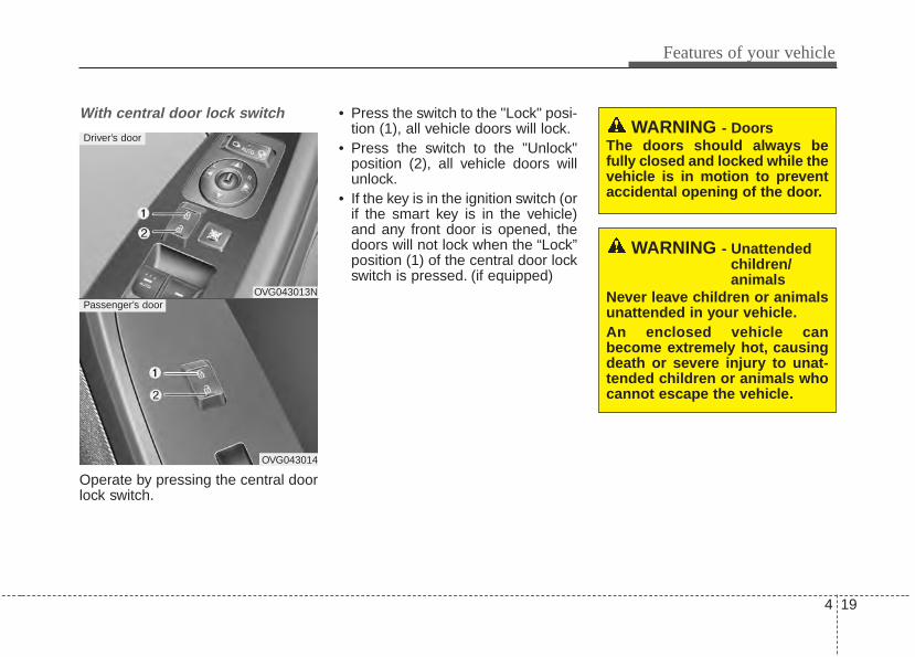
4 19
Features of your vehicle
With central door lock switch
Operate by pressing the central doorlock switch.
• Press the switch to the "Lock" posi-tion (1), all vehicle doors will lock.
• Press the switch to the "Unlock"position (2), all vehicle doors willunlock.
• If the key is in the ignition switch (orif the smart key is in the vehicle)and any front door is opened, thedoors will not lock when the “Lock”position (1) of the central door lockswitch is pressed. (if equipped)
OVG043013N
OVG043014
Driver’s door
Passenger’s door
WARNING - DoorsThe doors should always befully closed and locked while thevehicle is in motion to preventaccidental opening of the door.
WARNING - Unattendedchildren/animals
Never leave children or animalsunattended in your vehicle.An enclosed vehicle canbecome extremely hot, causingdeath or severe injury to unat-tended children or animals whocannot escape the vehicle.
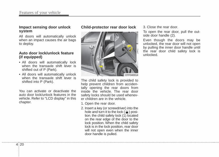
Features of your vehicle
204
Impact sensing door unlocksystemAll doors will automatically unlockwhen an impact causes the air bagsto deploy.
Auto door lock/unlock feature(if equipped)• All doors will automatically lock
when the transaxle shift lever isshifted out of P (Park).
• All doors will automatically unlockwhen the transaxle shift lever isshifted into P (Park).
You can activate or deactivate theauto door lock/unlock features in thevehicle. Refer to "LCD display" in thischapter.
Child-protector rear door lock
The child safety lock is provided tohelp prevent children from acciden-tally opening the rear doors frominside the vehicle. The rear doorsafety locks should be used whenev-er children are in the vehicle.1. Open the rear door.2. Insert a key (or screwdriver) into the
hole and turn it to the lock ( ) posi-tion. the child safety lock (1) locatedon the rear edge of the door to thelock position. When the child safetylock is in the lock position, rear doorwill not open even when the innerdoor handle is pulled.
3. Close the rear door.To open the rear door, pull the out-side door handle (2).Even though the doors may beunlocked, the rear door will not openby pulling the inner door handle untilthe rear door child safety lock isunlocked.
OTF040014
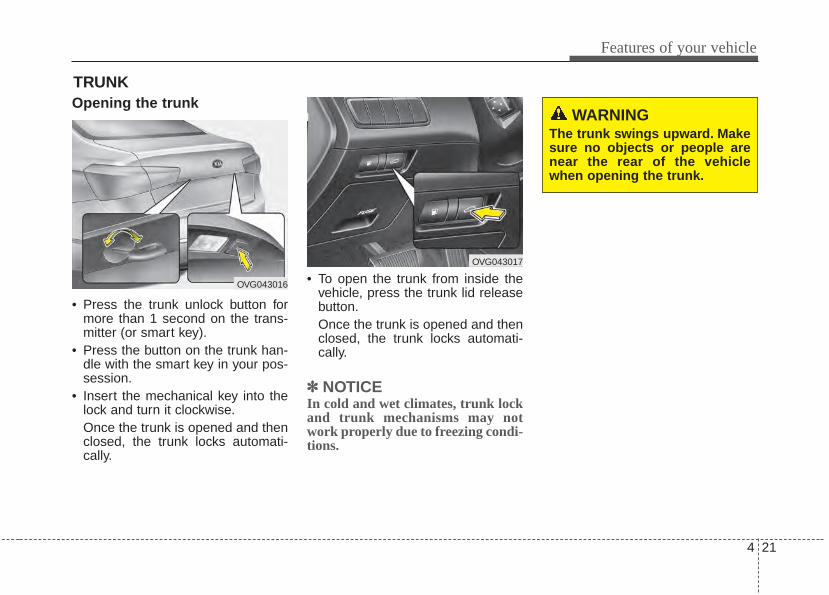
4 21
Features of your vehicle
Opening the trunk
• Press the trunk unlock button formore than 1 second on the trans-mitter (or smart key).
• Press the button on the trunk han-dle with the smart key in your pos-session.
• Insert the mechanical key into thelock and turn it clockwise.Once the trunk is opened and thenclosed, the trunk locks automati-cally.
• To open the trunk from inside thevehicle, press the trunk lid releasebutton.Once the trunk is opened and thenclosed, the trunk locks automati-cally.
✽✽ NOTICEIn cold and wet climates, trunk lockand trunk mechanisms may notwork properly due to freezing condi-tions.
TRUNK
OVG043016
OVG043017
WARNINGThe trunk swings upward. Makesure no objects or people arenear the rear of the vehiclewhen opening the trunk.
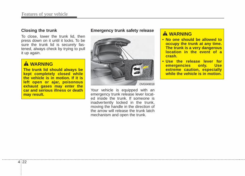
Features of your vehicle
224
Closing the trunkTo close, lower the trunk lid, thenpress down on it until it locks. To besure the trunk lid is securely fas-tened, always check by trying to pullit up again.
Emergency trunk safety release
Your vehicle is equipped with anemergency trunk release lever locat-ed inside the trunk. If someone isinadvertently locked in the trunk,moving the handle in the direction ofthe arrow will release the trunk latchmechanism and open the trunk.
WARNINGThe trunk lid should always bekept completely closed whilethe vehicle is in motion. If it isleft open or ajar, poisonousexhaust gases may enter thecar and serious illness or deathmay result.
OVG049018
WARNING• No one should be allowed to
occupy the trunk at any time.The trunk is a very dangerouslocation in the event of acrash.
• Use the release lever foremergencies only. Useextreme caution, especiallywhile the vehicle is in motion.
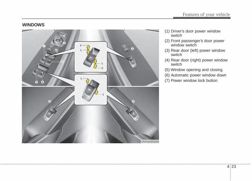
4 23
Features of your vehicle
(1) Driver’s door power windowswitch
(2) Front passenger’s door powerwindow switch
(3) Rear door (left) power windowswitch
(4) Rear door (right) power windowswitch
(5) Window opening and closing(6) Automatic power window down(7) Power window lock button
WINDOWS
OVG043020N
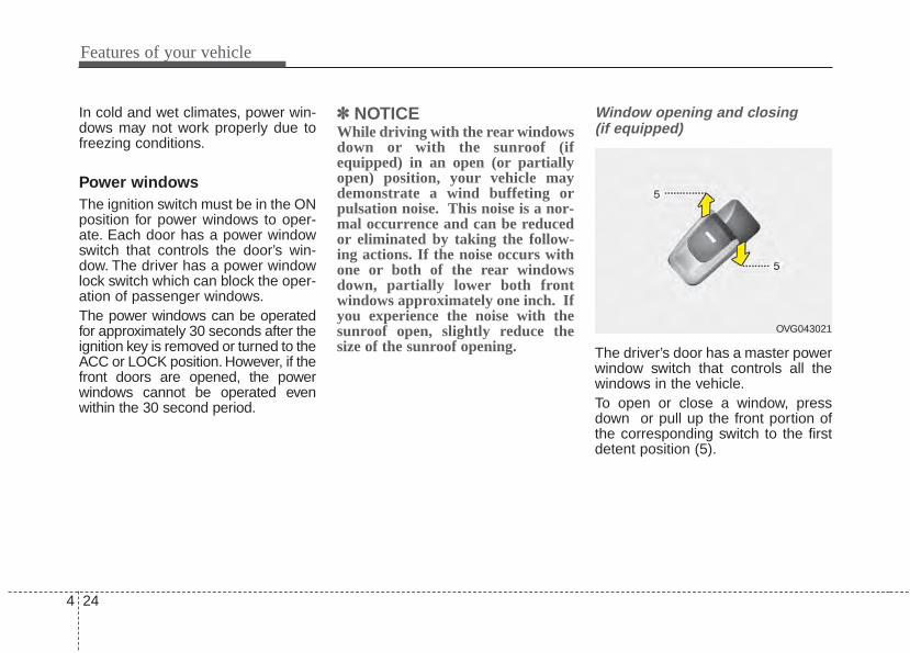
Features of your vehicle
244
In cold and wet climates, power win-dows may not work properly due tofreezing conditions.
Power windowsThe ignition switch must be in the ONposition for power windows to oper-ate. Each door has a power windowswitch that controls the door’s win-dow. The driver has a power windowlock switch which can block the oper-ation of passenger windows.The power windows can be operatedfor approximately 30 seconds after theignition key is removed or turned to theACC or LOCK position. However, if thefront doors are opened, the powerwindows cannot be operated evenwithin the 30 second period.
✽✽ NOTICEWhile driving with the rear windowsdown or with the sunroof (ifequipped) in an open (or partiallyopen) position, your vehicle maydemonstrate a wind buffeting orpulsation noise. This noise is a nor-mal occurrence and can be reducedor eliminated by taking the follow-ing actions. If the noise occurs withone or both of the rear windowsdown, partially lower both frontwindows approximately one inch. Ifyou experience the noise with thesunroof open, slightly reduce thesize of the sunroof opening.
Window opening and closing (if equipped)
The driver’s door has a master powerwindow switch that controls all thewindows in the vehicle.To open or close a window, pressdown or pull up the front portion ofthe corresponding switch to the firstdetent position (5).
OVG043021
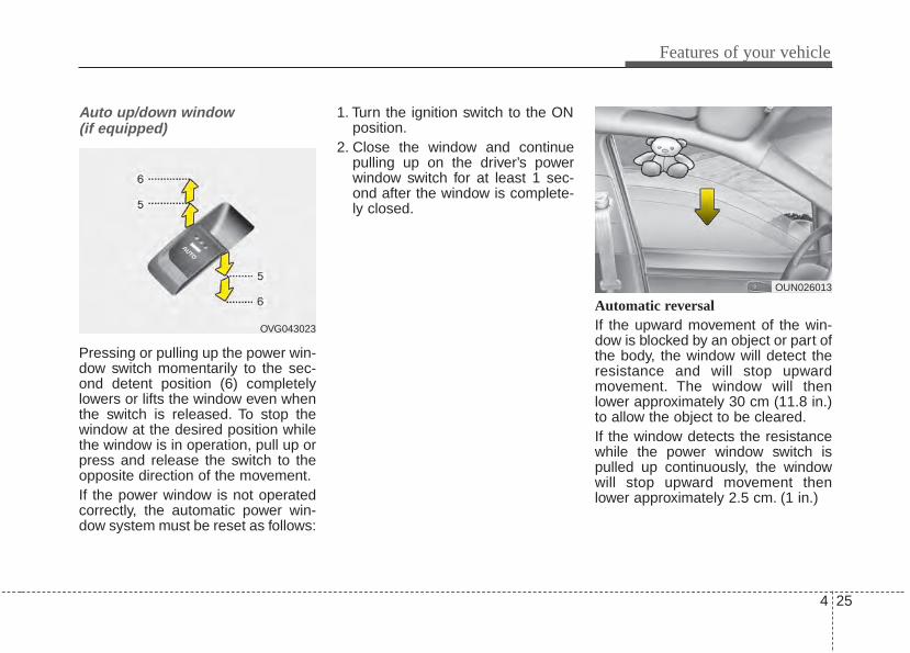
4 25
Features of your vehicle
Auto up/down window (if equipped)
Pressing or pulling up the power win-dow switch momentarily to the sec-ond detent position (6) completelylowers or lifts the window even whenthe switch is released. To stop thewindow at the desired position whilethe window is in operation, pull up orpress and release the switch to theopposite direction of the movement.If the power window is not operatedcorrectly, the automatic power win-dow system must be reset as follows:
1. Turn the ignition switch to the ONposition.
2. Close the window and continuepulling up on the driver’s powerwindow switch for at least 1 sec-ond after the window is complete-ly closed.
Automatic reversal If the upward movement of the win-dow is blocked by an object or part ofthe body, the window will detect theresistance and will stop upwardmovement. The window will thenlower approximately 30 cm (11.8 in.)to allow the object to be cleared.If the window detects the resistancewhile the power window switch ispulled up continuously, the windowwill stop upward movement thenlower approximately 2.5 cm. (1 in.)
OVG043023
OUN026013
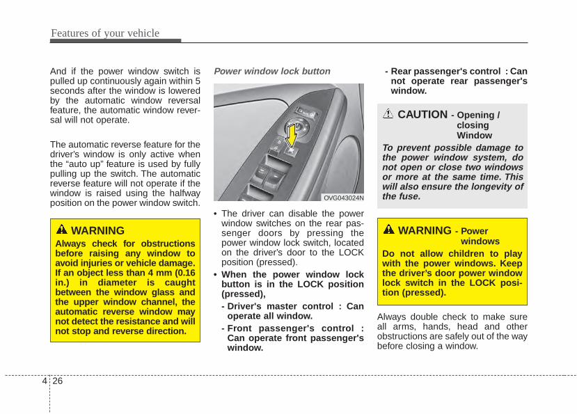
Features of your vehicle
264
And if the power window switch ispulled up continuously again within 5seconds after the window is loweredby the automatic window reversalfeature, the automatic window rever-sal will not operate.
The automatic reverse feature for thedriver’s window is only active whenthe “auto up” feature is used by fullypulling up the switch. The automaticreverse feature will not operate if thewindow is raised using the halfwayposition on the power window switch.
Power window lock button
• The driver can disable the powerwindow switches on the rear pas-senger doors by pressing thepower window lock switch, locatedon the driver’s door to the LOCKposition (pressed).
• When the power window lockbutton is in the LOCK position(pressed),- Driver's master control : Can
operate all window.- Front passenger's control :
Can operate front passenger'swindow.
- Rear passenger's control : Cannot operate rear passenger'swindow.
Always double check to make sureall arms, hands, head and otherobstructions are safely out of the waybefore closing a window.
WARNINGAlways check for obstructionsbefore raising any window toavoid injuries or vehicle damage.If an object less than 4 mm (0.16in.) in diameter is caughtbetween the window glass andthe upper window channel, theautomatic reverse window maynot detect the resistance and willnot stop and reverse direction.
OVG043024N
CAUTION - Opening / closingWindow
To prevent possible damage tothe power window system, donot open or close two windowsor more at the same time. Thiswill also ensure the longevity ofthe fuse.
WARNING - Power windows
Do not allow children to playwith the power windows. Keepthe driver’s door power windowlock switch in the LOCK posi-tion (pressed).

4 27
Features of your vehicle
HOOD Opening the hood
1. Pull the release lever to unlatchthe hood. The hood should popopen slightly.
Open the hood after turning off theengine on a flat surface, shifting theshift lever to the P(Park) position forautomatic transaxle and to the1st(First) gear or R(Reverse) formanual transaxle, and setting theparking brake.
2. Go to the front of the vehicle, raisethe hood slightly, push the second-ary latch (1) left of the hood centerand lift the hood (2).
3. Raise the hood. It will raise com-pletely by itself after it has beenraised about halfway.
OVG049025
OVG043026
WARNING• Always double check to be
sure that the hood is firmlylatched before driving away. Ifit is not latched, the hoodcould fly open while the vehi-cle is being driven, causing atotal loss of visibility, whichmight result in an accident.
• Do not move the vehicle withthe hood raised. The view willbe blocked and the hoodcould fall or be damaged.
Features of your vehicle
284
Closing the hood1. Before closing the hood, check the
following:• All filler caps in engine compart-
ment must be correctly installed.• Gloves, rags or any other com-
bustible material must be removedfrom the engine compartment.
2. Lower the hood halfway and pushdown to securely lock in place.
WARNING• Before closing the hood,
ensure that all obstructionsare removed from the hoodopening. Closing the hoodwith an obstruction present inthe hood opening may resultin property damage or severepersonal injury.
• Do not leave gloves, rags orany other combustible materi-al in the engine compartment.Doing so may cause a heat-induced fire.
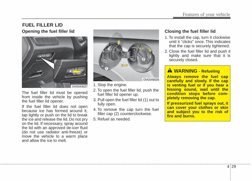
4 29
Features of your vehicle
FUEL FILLER LIDOpening the fuel filler lid
The fuel filler lid must be openedfrom inside the vehicle by pushingthe fuel filler lid opener.If the fuel filler lid does not openbecause ice has formed around it,tap lightly or push on the lid to breakthe ice and release the lid. Do not pryon the lid. If necessary, spray aroundthe lid with an approved de-icer fluid(do not use radiator anti-freeze) ormove the vehicle to a warm placeand allow the ice to melt.
1. Stop the engine.2. To open the fuel filler lid, push the
fuel filler lid opener up.3. Pull open the fuel filler lid (1) out to
fully open.4. To remove the cap turn the fuel
filler cap (2) counterclockwise.5. Refuel as needed.
Closing the fuel filler lid1. To install the cap, turn it clockwise
until it "clicks" once. This indicatesthat the cap is securely tightened.
2. Close the fuel filler lid and push itlightly and make sure that it issecurely closed.
WARNING - RefuelingAlways remove the fuel capcarefully and slowly. If the capis venting fuel or if you hear ahissing sound, wait until thecondition stops before com-pletely removing the cap.If pressurized fuel sprays out, itcan cover your clothes or skinand subject you to the risk offire and burns.
OVG043027
OVG049029
Features of your vehicle
304
Always check that the fuel cap isinstalled securely to prevent fuelspillage in the event of an accident.
✽✽ NOTICEWhen using an approved portablefuel container, be sure to place thecontainer on the ground prior torefueling. Static electricity dischargefrom the container can ignite fuelvapors causing a fire. Once refuelinghas begun, contact with the vehicleshould be maintained until the fill-ing is complete. Use only approvedportable plastic fuel containersdesigned to carry and store gasoline.
WARNING - Fire/explo-sion risk
Read and follow all warningsposted at the gas station facili-ty. Failure to follow all warningswill result in severe personalinjury, severe burns or deathdue to fire or explosion.
WARNING - Cell phonefires
Do not use cellular phoneswhile refueling. Electric currentand/or electronic interferencefrom cellular phones can poten-tially ignite fuel vapors causinga fire.
WARNING - Static electricity
• Before touching the fuel noz-zle, you should eliminatepotentially dangerous staticelectricity discharge by touch-ing another metal part of thevehicle, a safe distance awayfrom the fuel filler neck, noz-zle, or other gas source.
• Do not get back into a vehicleonce you have begun refuel-ing since you can generatestatic electricity by touching,rubbing or sliding against anyitem or fabric (polyester, satin,nylon, etc.) capable of produc-ing static electricity. Staticelectricity discharge canignite fuel vapors resulting inrapid burning. If you must re-enter the vehicle, you shouldonce again eliminate poten-tially dangerous static elec-tricity discharge by touching ametal part of the vehicle, awayfrom the fuel filler neck, noz-zle or other gasoline source.
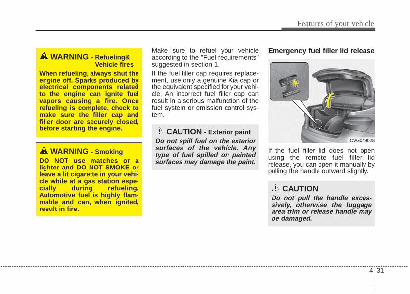
4 31
Features of your vehicle
Make sure to refuel your vehicleaccording to the "Fuel requirements"suggested in section 1.If the fuel filler cap requires replace-ment, use only a genuine Kia cap orthe equivalent specified for your vehi-cle. An incorrect fuel filler cap canresult in a serious malfunction of thefuel system or emission control sys-tem.
Emergency fuel filler lid release
If the fuel filler lid does not openusing the remote fuel filler lidrelease, you can open it manually bypulling the handle outward slightly.
CAUTION - Exterior paintDo not spill fuel on the exteriorsurfaces of the vehicle. Anytype of fuel spilled on paintedsurfaces may damage the paint.
WARNING - Refueling&Vehicle fires
When refueling, always shut theengine off. Sparks produced byelectrical components relatedto the engine can ignite fuelvapors causing a fire. Oncerefueling is complete, check tomake sure the filler cap andfiller door are securely closed,before starting the engine.
WARNING - SmokingDO NOT use matches or alighter and DO NOT SMOKE orleave a lit cigarette in your vehi-cle while at a gas station espe-cially during refueling.Automotive fuel is highly flam-mable and can, when ignited,result in fire.
CAUTIONDo not pull the handle exces-sively, otherwise the luggagearea trim or release handle maybe damaged.
OVG049028
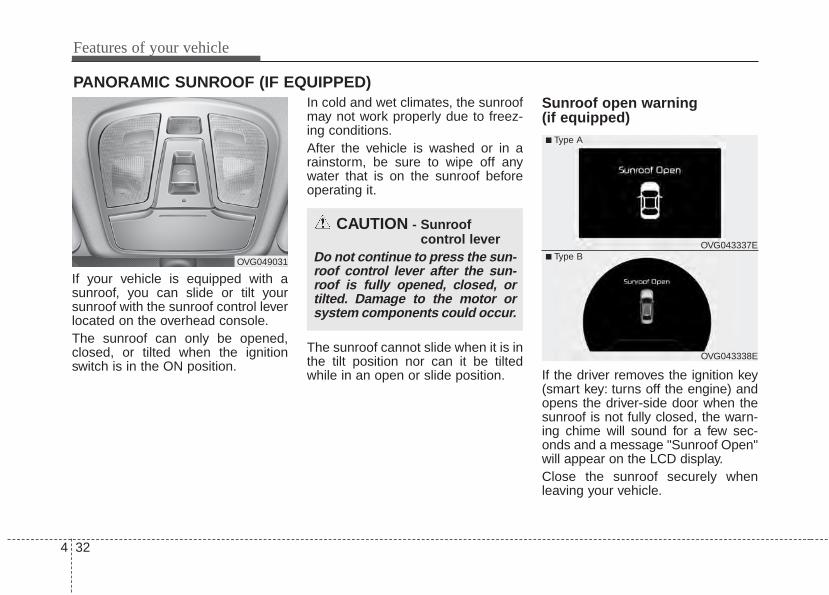
Features of your vehicle
324
PANORAMIC SUNROOF (IF EQUIPPED)
If your vehicle is equipped with asunroof, you can slide or tilt yoursunroof with the sunroof control leverlocated on the overhead console.The sunroof can only be opened,closed, or tilted when the ignitionswitch is in the ON position.
In cold and wet climates, the sunroofmay not work properly due to freez-ing conditions.After the vehicle is washed or in arainstorm, be sure to wipe off anywater that is on the sunroof beforeoperating it.
The sunroof cannot slide when it is inthe tilt position nor can it be tiltedwhile in an open or slide position.
Sunroof open warning (if equipped)
If the driver removes the ignition key(smart key: turns off the engine) andopens the driver-side door when thesunroof is not fully closed, the warn-ing chime will sound for a few sec-onds and a message "Sunroof Open"will appear on the LCD display.Close the sunroof securely whenleaving your vehicle.
CAUTION - Sunroof control lever
Do not continue to press the sun-roof control lever after the sun-roof is fully opened, closed, ortilted. Damage to the motor orsystem components could occur.
OVG049031
OVG043338E
■ Type A
■ Type BOVG043337E
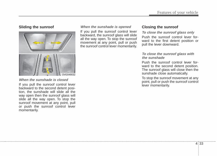
4 33
Features of your vehicle
Sliding the sunroof
When the sunshade is closedIf you pull the sunroof control leverbackward to the second detent posi-tion, the sunshade will slide all theway open then the sunroof glass willslide all the way open. To stop thesunroof movement at any point, pullor push the sunroof control levermomentarily.
When the sunshade is openedIf you pull the sunroof control leverbackward, the sunroof glass will slideall the way open. To stop the sunroofmovement at any point, pull or pushthe sunroof control lever momentarily.
Closing the sunroofTo close the sunroof glass onlyPush the sunroof control lever for-ward to the first detent position orpull the lever downward.
To close the sunroof glass withthe sunshade Push the sunroof control lever for-ward to the second detent position.The sunroof glass will close then thesunshade close automatically.To stop the sunroof movement at anypoint, pull or push the sunroof controllever momentarily.
OVG049032
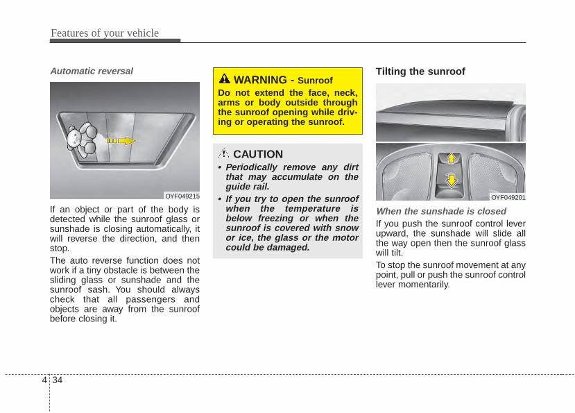
Features of your vehicle
344
Automatic reversal
If an object or part of the body isdetected while the sunroof glass orsunshade is closing automatically, itwill reverse the direction, and thenstop.The auto reverse function does notwork if a tiny obstacle is between thesliding glass or sunshade and thesunroof sash. You should alwayscheck that all passengers andobjects are away from the sunroofbefore closing it.
Tilting the sunroof
When the sunshade is closedIf you push the sunroof control leverupward, the sunshade will slide allthe way open then the sunroof glasswill tilt.To stop the sunroof movement at anypoint, pull or push the sunroof controllever momentarily.
WARNING - SunroofDo not extend the face, neck,arms or body outside throughthe sunroof opening while driv-ing or operating the sunroof.
CAUTION• Periodically remove any dirt
that may accumulate on theguide rail.
• If you try to open the sunroofwhen the temperature isbelow freezing or when thesunroof is covered with snowor ice, the glass or the motorcould be damaged.
OYF049215 OYF049201
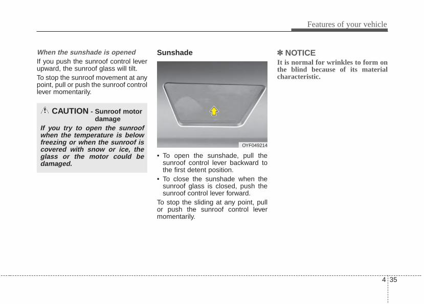
4 35
Features of your vehicle
When the sunshade is openedIf you push the sunroof control leverupward, the sunroof glass will tilt.To stop the sunroof movement at anypoint, pull or push the sunroof controllever momentarily.
Sunshade
• To open the sunshade, pull thesunroof control lever backward tothe first detent position.
• To close the sunshade when thesunroof glass is closed, push thesunroof control lever forward.
To stop the sliding at any point, pullor push the sunroof control levermomentarily.
✽✽ NOTICEIt is normal for wrinkles to form onthe blind because of its materialcharacteristic.
CAUTION - Sunroof motordamage
If you try to open the sunroofwhen the temperature is belowfreezing or when the sunroof iscovered with snow or ice, theglass or the motor could bedamaged.
OYF049214
Features of your vehicle
364
Resetting the sunroofWhenever the vehicle battery is dis-connected or discharged, or relatedfuse is blown, you must reset yoursunroof system as follows:
1. Turn the ignition switch to the ONposition and close the sunroofcompletely.
2. Release the control lever.3. Push and hold the control lever for-
ward (for more than 10 seconds)until the sunroof tilts and slightlymoves. Then, release the lever.
4. Push the sunroof control lever for-ward in the direction of close untilthe sunroof operates as follows:
SUNSHADE OPEN → TILT OPEN→ SLIDE OPEN → SLIDE CLOSE→ SUNSHADE CLOSE
Then, release the control lever.
When this is complete, the sunroofsystem is reset.
❈ For more detailed information,contact an authorized Kia dealer.
✽✽ NOTICEIf the sunroof is not reset when thevehicle battery is disconnected ordischarged, or related fuse is blown,the sunroof may operate improperly.
4 37
Features of your vehicle
STEERING WHEELElectric power steering (EPS)Power steering uses the motor toassist you in steering the vehicle. Ifthe engine is off or if the power steer-ing system becomes inoperative, thevehicle may still be steered, but it willrequire increased steering effort.The motor driven power steering iscontrolled by the power steering con-trol unit which senses the steeringwheel torque and vehicle speed tocommand the motor.The steering wheel becomes heavieras the vehicle’s speed increases andbecomes lighter as the vehicle’sspeed decreases for better control ofthe steering wheel.Should you notice any change in theeffort required to steer during normalvehicle operation, have the powersteering checked by an authorizedKia dealer.
✽✽ NOTICEThe following symptoms may occurduring normal vehicle operation:• The steering effort is increased
immediately after turning the igni-tion switch on. This happens as thesystem performs the EPS systemdiagnostics. When the diagnosticsare completed, the steering wheelwill return to its normal condition
• A click noise may be heard fromthe EPS relay after the ignitionswitch is turned to the ON orLOCK position.
• Motor noise may be heard whenthe vehicle is at a stop or at a lowdriving speed.
• The steering effort increases if thesteering wheel is rotated continu-ously when the vehicle is not inmotion. However, after a few min-utes, it will return to its normalconditions.
• When you operate the steeringwheel in low temperature, abnor-mal noise could occur. If tempera-ture rises, the noise will disappear.This is a normal condition.
If the Electric Power Steering Systemdoes not operate normally, the warn-ing light will illuminate on the instru-ment cluster.The steering wheel maybecome difficult to control or operateabnormally. Take your vehicle to anauthorized Kia dealer and have thevehicle checked as soon as possible.
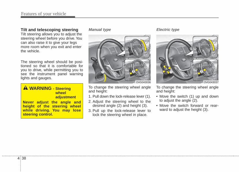
Features of your vehicle
384
Tilt and telescoping steeringTilt steering allows you to adjust thesteering wheel before you drive. Youcan also raise it to give your legsmore room when you exit and enterthe vehicle.
The steering wheel should be posi-tioned so that it is comfortable foryou to drive, while permitting you tosee the instrument panel warninglights and gauges.
Manual type
To change the steering wheel angleand height:1. Pull down the lock-release lever (1).2. Adjust the steering wheel to the
desired angle (2) and height (3).3. Pull up the lock-release lever to
lock the steering wheel in place.
Electric type
To change the steering wheel angleand height:• Move the switch (1) up and down
to adjust the angle (2).• Move the switch forward or rear-
ward to adjust the height (3).
WARNING - Steeringwheel adjustment
Never adjust the angle andheight of the steering wheelwhile driving. You may losesteering control.
OVG043036 OVG043037
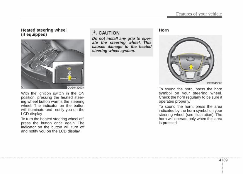
4 39
Features of your vehicle
Heated steering wheel (if equipped)
With the ignition switch in the ONposition, pressing the heated steer-ing wheel button warms the steeringwheel. The indicator on the buttonwill illuminate and notify you on theLCD display.To turn the heated steering wheel off,press the button once again. Theindicator on the button will turn offand notify you on the LCD display.
Horn
To sound the horn, press the hornsymbol on your steering wheel.Check the horn regularly to be sure itoperates properly.To sound the horn, press the areaindicated by the horn symbol on yoursteering wheel (see illustration). Thehorn will operate only when this areais pressed.
CAUTIONDo not install any grip to oper-ate the steering wheel. Thiscauses damage to the heatedsteering wheel system.
OVG043200N
OXM043305
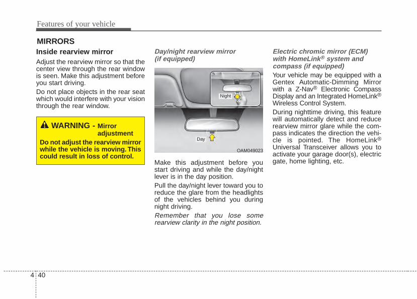
Features of your vehicle
404
MIRRORS Inside rearview mirrorAdjust the rearview mirror so that thecenter view through the rear windowis seen. Make this adjustment beforeyou start driving.Do not place objects in the rear seatwhich would interfere with your visionthrough the rear window.
Day/night rearview mirror (if equipped)
Make this adjustment before youstart driving and while the day/nightlever is in the day position.Pull the day/night lever toward you toreduce the glare from the headlightsof the vehicles behind you duringnight driving.Remember that you lose somerearview clarity in the night position.
Electric chromic mirror (ECM)with HomeLink® system and compass (if equipped)Your vehicle may be equipped with aGentex Automatic-Dimming Mirrorwith a Z-Nav® Electronic CompassDisplay and an Integrated HomeLink®
Wireless Control System.During nighttime driving, this featurewill automatically detect and reducerearview mirror glare while the com-pass indicates the direction the vehi-cle is pointed. The HomeLink®
Universal Transceiver allows you toactivate your garage door(s), electricgate, home lighting, etc.
WARNING - Mirror adjustment
Do not adjust the rearview mirrorwhile the vehicle is moving. Thiscould result in loss of control.
OAM049023
Day
Night
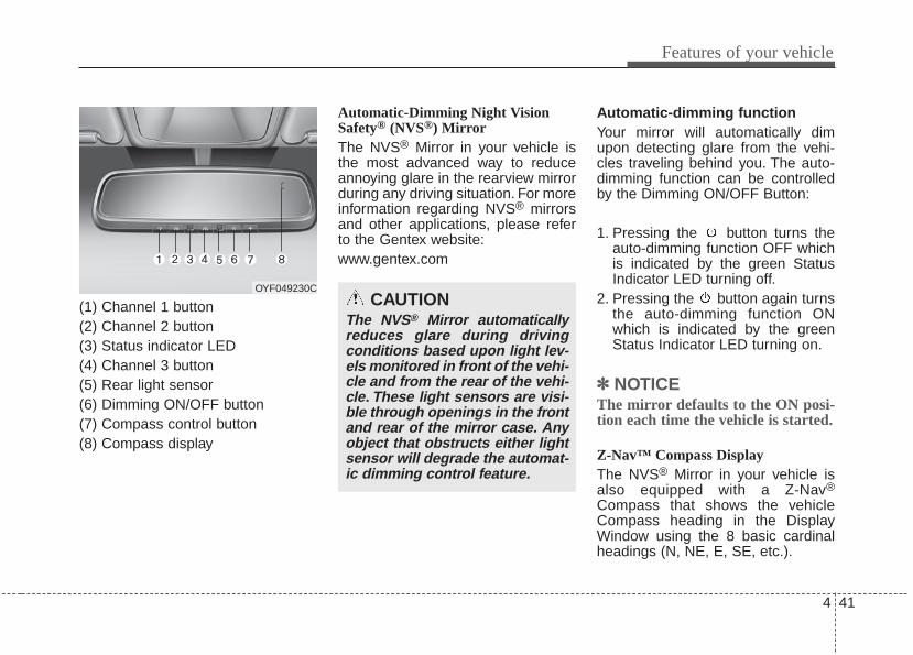
4 41
Features of your vehicle
(1) Channel 1 button(2) Channel 2 button(3) Status indicator LED(4) Channel 3 button(5) Rear light sensor(6) Dimming ON/OFF button(7) Compass control button(8) Compass display
Automatic-Dimming Night VisionSafety® (NVS®) MirrorThe NVS® Mirror in your vehicle isthe most advanced way to reduceannoying glare in the rearview mirrorduring any driving situation. For moreinformation regarding NVS® mirrorsand other applications, please referto the Gentex website:www.gentex.com
Automatic-dimming functionYour mirror will automatically dimupon detecting glare from the vehi-cles traveling behind you. The auto-dimming function can be controlledby the Dimming ON/OFF Button:
1. Pressing the button turns theauto-dimming function OFF whichis indicated by the green StatusIndicator LED turning off.
2. Pressing the button again turnsthe auto-dimming function ONwhich is indicated by the greenStatus Indicator LED turning on.
✽✽ NOTICEThe mirror defaults to the ON posi-tion each time the vehicle is started.
Z-Nav™ Compass DisplayThe NVS® Mirror in your vehicle isalso equipped with a Z-Nav®
Compass that shows the vehicleCompass heading in the DisplayWindow using the 8 basic cardinalheadings (N, NE, E, SE, etc.).
OYF049230CCAUTION
The NVS® Mirror automaticallyreduces glare during drivingconditions based upon light lev-els monitored in front of the vehi-cle and from the rear of the vehi-cle. These light sensors are visi-ble through openings in the frontand rear of the mirror case. Anyobject that obstructs either lightsensor will degrade the automat-ic dimming control feature.
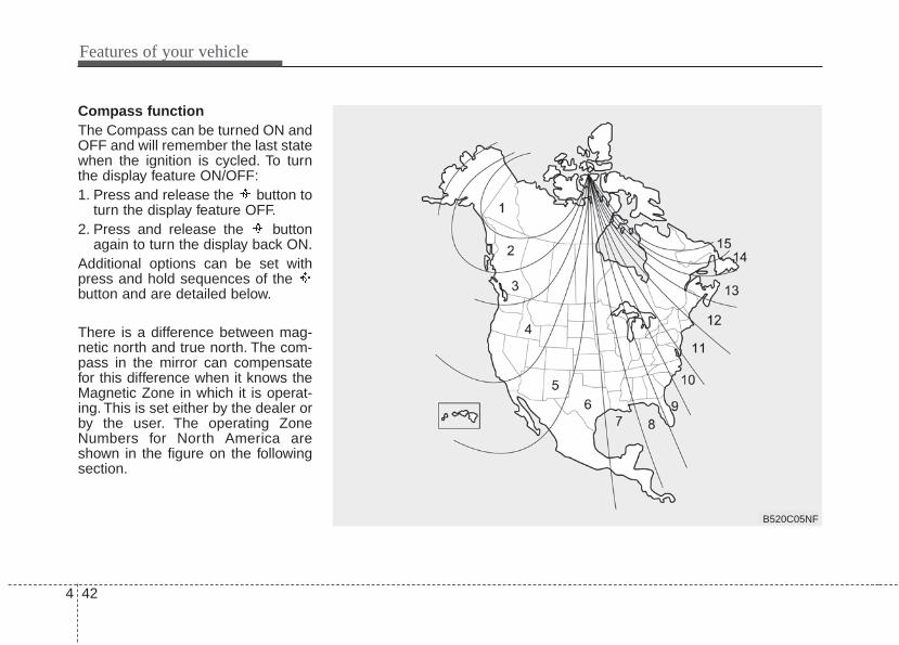
Features of your vehicle
424
Compass functionThe Compass can be turned ON andOFF and will remember the last statewhen the ignition is cycled. To turnthe display feature ON/OFF:1. Press and release the button to
turn the display feature OFF.2. Press and release the button
again to turn the display back ON.Additional options can be set withpress and hold sequences of the button and are detailed below.
There is a difference between mag-netic north and true north. The com-pass in the mirror can compensatefor this difference when it knows theMagnetic Zone in which it is operat-ing. This is set either by the dealer orby the user. The operating ZoneNumbers for North America areshown in the figure on the followingsection.
B520C05NF
4 43
Features of your vehicle
To adjust the Zone setting:1. Determine the desired Zone
Number based upon your currentlocation on the Zone Map.
2. Press and hold the button formore than 3 but less than 6 sec-onds, the current Zone Numberwill appear on the display.
3. Pressing and holding the buttonagain will cause the numbers toincrement (Note: they will repeat…13, 14, 15, 1, 2, …). Releasingthe button when the desired ZoneNumber appears on the displaywill set the new Zone.
4. Within about 5 seconds the com-pass will start displaying a com-pass heading again.
There are some conditions that cancause changes to the vehicle mag-nets, such as installing a ski rack ora CB antenna. Body repair work onthe vehicle can also cause changesto the vehicle's magnetic field. Inthese situations, the compass willneed to be re-calibrated to quicklycorrect for these changes. To re-cali-brate the compass:1. Press and hold the button for
more than 6 seconds. When thecompass memory is cleared a "C"will appear in the display.
2. To calibrate the compass, drivethe vehicle in 2 complete circles atless than 5 mph (8 km/h).
Integrated HomeLink®Wireless Control SystemThe HomeLink® Wireless ControlSystem provides a convenient way toreplace up to three hand-held radio-frequency (RF) transmitters with asingle built-in device. This innovativefeature will learn the radio frequencycodes of most current transmitters tooperate devices such as gate opera-tors, garage door openers, entrydoor locks, security systems, evenhome lighting. Both standard androlling code-equipped transmitterscan be programmed by following theoutlined procedures. AdditionalHomeLink® information can be foundat: www.homelink.com or by calling1-800-355-3515.
Features of your vehicle
444
Retain the original transmitter of theRF device you are programming foruse in other vehicles as well as forfuture HomeLink® programming. It isalso suggested that upon the sale ofthe vehicle, the programmedHomeLink® buttons be erased forsecurity purposes.
Programming HomeLink®
✽✽ NOTICE• When programming a garage
door opener, it is advised to parkthe vehicle outside of the garage.
• It is recommended that a new bat-tery be placed in the hand-heldtransmitter of the device being pro-grammed to HomeLink® for quick-er training and accurate transaxleof the radio-frequency signal.
• Some vehicles may require theignition switch to be turned to thesecond (or "accessories") positionfor programming and/or opera-tion of HomeLink®.
• In the event that there are still pro-gramming difficulties or questionsafter following the programmingsteps listed below, contactHomeLink® at: www.homelink.comor 1-800-355-3515.
CAUTIONBefore programming HomeLink®
to a garage door opener or gateoperator, make sure that peopleand objects are out of the way ofthe device to prevent potentialharm or damage. Do not useHomeLink® with any garage dooropener that lacks the safety stopand reverse features required byU.S. federal safety standards(this includes any garage dooropener model manufacturedbefore April 1, 1982). A garagedoor that cannot detect an object- signaling the door to stop andreverse - does not meet currentU.S. federal safety standards.Using a garage door opener with-out these features increases therisk of serious injury or death.
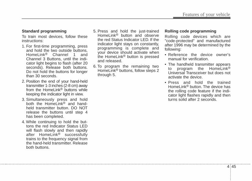
4 45
Features of your vehicle
Standard programmingTo train most devices, follow theseinstructions:1. For first-time programming, press
and hold the two outside buttons,HomeLink® Channel 1 andChannel 3 Buttons, until the indi-cator light begins to flash (after 20seconds). Release both buttons.Do not hold the buttons for longerthan 30 seconds.
2. Position the end of your hand-heldtransmitter 1-3 inches (2-8 cm) awayfrom the HomeLink® buttons whilekeeping the indicator light in view.
3. Simultaneously press and holdboth the HomeLink® and hand-held transmitter button. DO NOTrelease the buttons until step 4has been completed.
4. While continuing to hold the but-tons the red Indicator Status LEDwill flash slowly and then rapidlyafter HomeLink® successfullytrains to the frequency signal fromthe hand-held transmitter. Releaseboth buttons.
5. Press and hold the just-trainedHomeLink® button and observethe red Status Indicator LED. If theindicator light stays on constantly,programming is complete andyour device should activate whenthe HomeLink® button is pressedand released.
6. To program the remaining twoHomeLink® buttons, follow steps 2through 5.
Rolling code programmingRolling code devices which are"code-protected" and manufacturedafter 1996 may be determined by thefollowing:• Reference the device owner's
manual for verification.• The handheld transmitter appears
to program the HomeLink®
Universal Transceiver but does notactivate the device.
• Press and hold the trainedHomeLink® button. The device hasthe rolling code feature if the indi-cator light flashes rapidly and thenturns solid after 2 seconds.
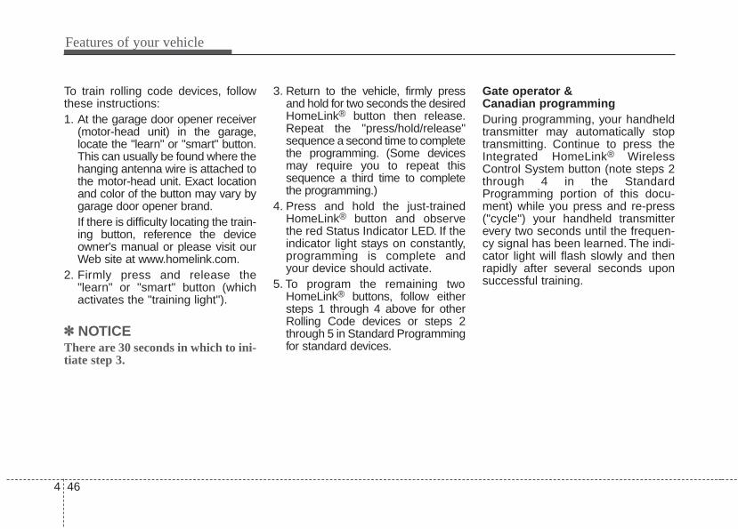
Features of your vehicle
464
To train rolling code devices, followthese instructions:1. At the garage door opener receiver
(motor-head unit) in the garage,locate the "learn" or "smart" button.This can usually be found where thehanging antenna wire is attached tothe motor-head unit. Exact locationand color of the button may vary bygarage door opener brand.If there is difficulty locating the train-ing button, reference the deviceowner's manual or please visit ourWeb site at www.homelink.com.
2. Firmly press and release the"learn" or "smart" button (whichactivates the "training light").
✽✽ NOTICEThere are 30 seconds in which to ini-tiate step 3.
3. Return to the vehicle, firmly pressand hold for two seconds the desiredHomeLink® button then release.Repeat the "press/hold/release"sequence a second time to completethe programming. (Some devicesmay require you to repeat thissequence a third time to completethe programming.)
4. Press and hold the just-trainedHomeLink® button and observethe red Status Indicator LED. If theindicator light stays on constantly,programming is complete andyour device should activate.
5. To program the remaining twoHomeLink® buttons, follow eithersteps 1 through 4 above for otherRolling Code devices or steps 2through 5 in Standard Programmingfor standard devices.
Gate operator & Canadian programmingDuring programming, your handheldtransmitter may automatically stoptransmitting. Continue to press theIntegrated HomeLink® WirelessControl System button (note steps 2through 4 in the StandardProgramming portion of this docu-ment) while you press and re-press("cycle") your handheld transmitterevery two seconds until the frequen-cy signal has been learned. The indi-cator light will flash slowly and thenrapidly after several seconds uponsuccessful training.
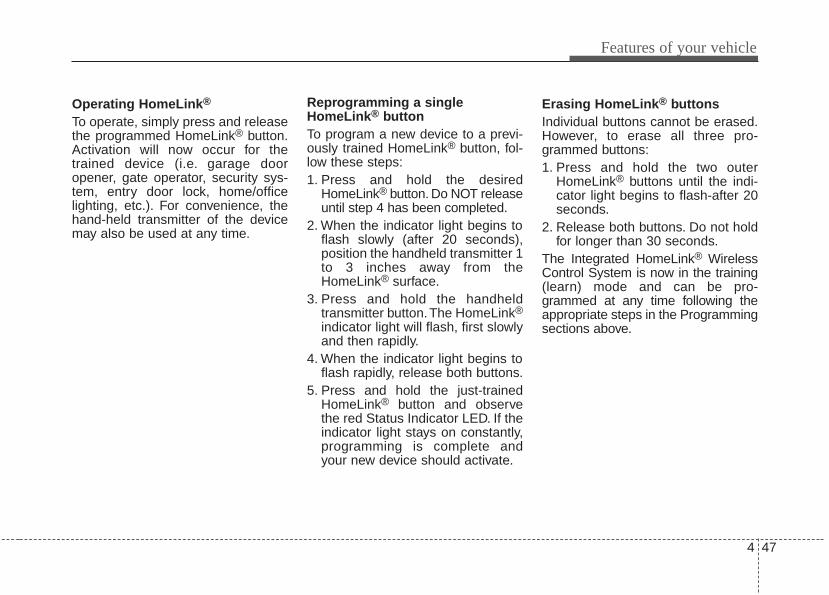
4 47
Features of your vehicle
Operating HomeLink®
To operate, simply press and releasethe programmed HomeLink® button.Activation will now occur for thetrained device (i.e. garage dooropener, gate operator, security sys-tem, entry door lock, home/officelighting, etc.). For convenience, thehand-held transmitter of the devicemay also be used at any time.
Reprogramming a singleHomeLink® buttonTo program a new device to a previ-ously trained HomeLink® button, fol-low these steps:1. Press and hold the desired
HomeLink® button. Do NOT releaseuntil step 4 has been completed.
2. When the indicator light begins toflash slowly (after 20 seconds),position the handheld transmitter 1to 3 inches away from theHomeLink® surface.
3. Press and hold the handheldtransmitter button.The HomeLink®
indicator light will flash, first slowlyand then rapidly.
4. When the indicator light begins toflash rapidly, release both buttons.
5. Press and hold the just-trainedHomeLink® button and observethe red Status Indicator LED. If theindicator light stays on constantly,programming is complete andyour new device should activate.
Erasing HomeLink® buttonsIndividual buttons cannot be erased.However, to erase all three pro-grammed buttons:1. Press and hold the two outer
HomeLink® buttons until the indi-cator light begins to flash-after 20seconds.
2. Release both buttons. Do not holdfor longer than 30 seconds.
The Integrated HomeLink® WirelessControl System is now in the training(learn) mode and can be pro-grammed at any time following theappropriate steps in the Programmingsections above.
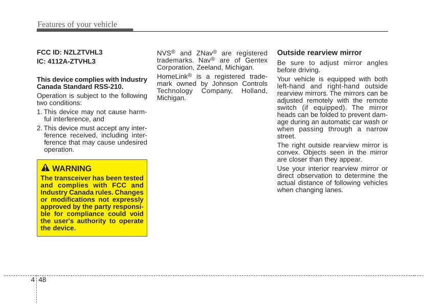
Features of your vehicle
484
FCC ID: NZLZTVHL3IC: 4112A-ZTVHL3
This device complies with IndustryCanada Standard RSS-210.Operation is subject to the followingtwo conditions:1. This device may not cause harm-
ful interference, and2. This device must accept any inter-
ference received, including inter-ference that may cause undesiredoperation.
NVS® and ZNav® are registeredtrademarks. Nav® are of GentexCorporation, Zeeland, Michigan.HomeLink® is a registered trade-mark owned by Johnson ControlsTechnology Company, Holland,Michigan.
Outside rearview mirrorBe sure to adjust mirror anglesbefore driving.Your vehicle is equipped with bothleft-hand and right-hand outsiderearview mirrors. The mirrors can beadjusted remotely with the remoteswitch (if equipped). The mirrorheads can be folded to prevent dam-age during an automatic car wash orwhen passing through a narrowstreet.The right outside rearview mirror isconvex. Objects seen in the mirrorare closer than they appear.Use your interior rearview mirror ordirect observation to determine theactual distance of following vehicleswhen changing lanes.
WARNINGThe transceiver has been testedand complies with FCC andIndustry Canada rules. Changesor modifications not expresslyapproved by the party responsi-ble for compliance could voidthe user's authority to operatethe device.
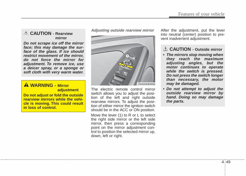
4 49
Features of your vehicle
Adjusting outside rearview mirror
The electric remote control mirrorswitch allows you to adjust the posi-tion of the left and right outsiderearview mirrors. To adjust the posi-tion of either mirror the ignition switchshould be in the ACC or ON position.Move the lever (1) to R or L to selectthe right side mirror or the left sidemirror, then press a correspondingpoint on the mirror adjustment con-trol to position the selected mirror up,down, left or right.
After the adjustment, put the leverinto neutral (center) position to pre-vent inadvertent adjustment.
CAUTION - Outside mirror• The mirrors stop moving when
they reach the maximumadjusting angles, but themotor continues to operatewhile the switch is pressed.Do not press the switch longerthan necessary, the motormay be damaged.
• Do not attempt to adjust theoutside rearview mirror byhand. Doing so may damagethe parts.
CAUTION - Rearview mirror
Do not scrape ice off the mirrorface; this may damage the sur-face of the glass. If ice shouldrestrict movement of the mirror,do not force the mirror foradjustment. To remove ice, usea deicer spray, or a sponge orsoft cloth with very warm water.
WARNING - Mirror adjustment
Do not adjust or fold the outsiderearview mirrors while the vehi-cle is moving. This could resultin loss of control.
OVG043045N
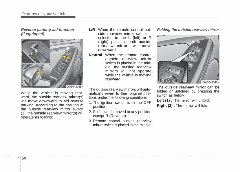
Features of your vehicle
504
Reverse parking aid function (if equipped)
While the vehicle is moving rear-ward, the outside rearview mirror(s)will move downward to aid reverseparking. According to the position ofthe outside rearview mirror switch(1), the outside rearview mirror(s) willoperate as follows:
L/R : When the remote control out-side rearview mirror switch isselected to the L (left) or R(right) position, both outsiderearview mirrors will movedownward.
Neutral : When the remote controloutside rearview mirrorswitch is placed in the mid-dle, the outside rearviewmirrors will not operatewhile the vehicle is movingrearward.
The outside rearview mirrors will auto-matically revert to their original posi-tions under the following conditions:1. The ignition switch is in the OFF
position.2. Shift lever is moved to any position
except R (Reverse).3. Remote control outside rearview
mirror switch is placed in the middle.
Folding the outside rearview mirror
The outside rearview mirror can befolded or unfolded by pressing theswitch as below.Left (1) : The mirror will unfold.Right (2) : The mirror will fold.
OVG043035N
OVG043046N
4 51
Features of your vehicle
Center (AUTO, 3) :The mirror will fold or unfold auto-matically as follows:• The mirror will fold or unfold when
the door is locked or unlocked bythe smart key.
• The mirror will fold or unfold whenthe door is locked or unlocked bythe button on the outside door han-dle.
• The mirror will unfold when youapproach the vehicle (all doorsclosed and locked) with a smartkey in possession. (if equipped)
CAUTION - Electric type outside
rearview mirrorThe electric type outsiderearview mirror operates eventhough the ignition switch is inthe OFF position. However, toprevent unnecessary batterydischarge, do not adjust themirrors longer than necessarywhile the engine is not running.In case it is an electric type out-side rearview mirror, don’t fold itby hand. It could cause motorfailure.
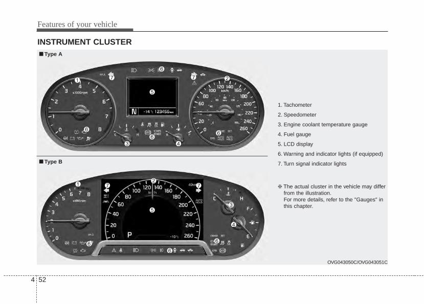
Features of your vehicle
524
INSTRUMENT CLUSTER
1. Tachometer
2. Speedometer
3. Engine coolant temperature gauge
4. Fuel gauge
5. LCD display
6. Warning and indicator lights (if equipped)
7. Turn signal indicator lights
OVG043050C/OVG043051C
■■ Type A
❈ The actual cluster in the vehicle may differfrom the illustration.For more details, refer to the "Gauges" inthis chapter.
■■ Type B
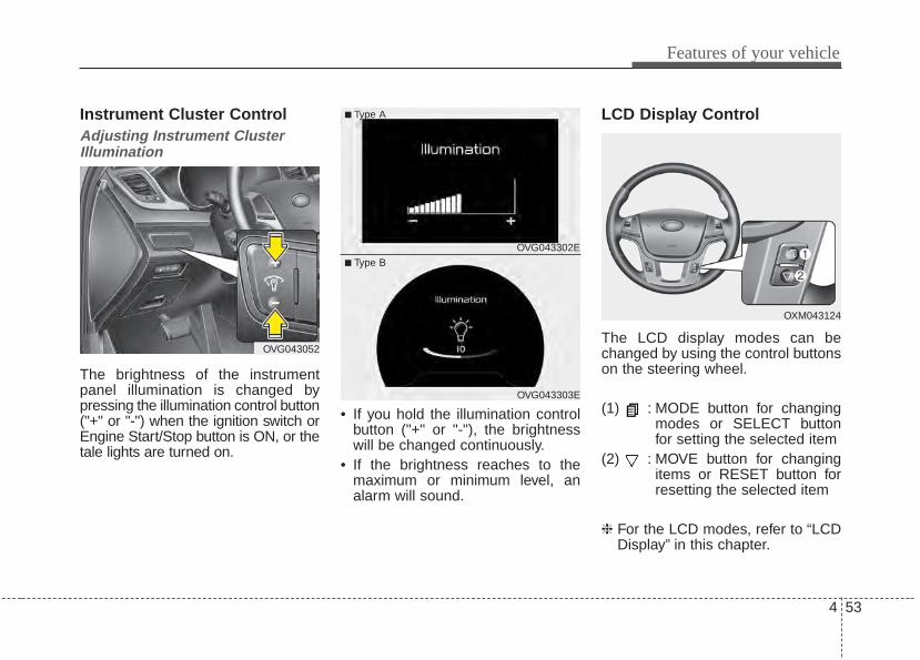
4 53
Features of your vehicle
Instrument Cluster ControlAdjusting Instrument ClusterIllumination
The brightness of the instrumentpanel illumination is changed bypressing the illumination control button("+" or "-") when the ignition switch orEngine Start/Stop button is ON, or thetale lights are turned on.
• If you hold the illumination controlbutton ("+" or "-"), the brightnesswill be changed continuously.
• If the brightness reaches to themaximum or minimum level, analarm will sound.
LCD Display Control
The LCD display modes can bechanged by using the control buttonson the steering wheel.
(1) : MODE button for changingmodes or SELECT buttonfor setting the selected item
(2) : MOVE button for changingitems or RESET button forresetting the selected item
❈ For the LCD modes, refer to “LCDDisplay” in this chapter.
OVG043052
OXM043124
OVG043302E
OVG043303E
■ Type A
■ Type B
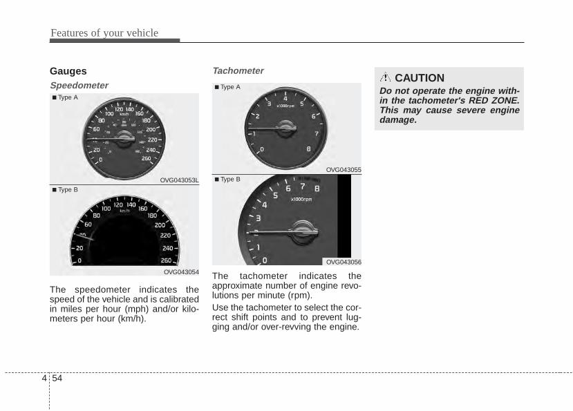
Features of your vehicle
544
GaugesSpeedometer
The speedometer indicates thespeed of the vehicle and is calibratedin miles per hour (mph) and/or kilo-meters per hour (km/h).
Tachometer
The tachometer indicates theapproximate number of engine revo-lutions per minute (rpm).Use the tachometer to select the cor-rect shift points and to prevent lug-ging and/or over-revving the engine.
CAUTIONDo not operate the engine with-in the tachometer's RED ZONE.This may cause severe enginedamage.
OVG043055
OVG043056
■ Type A
■ Type BOVG043053L
OVG043054
■ Type A
■ Type B
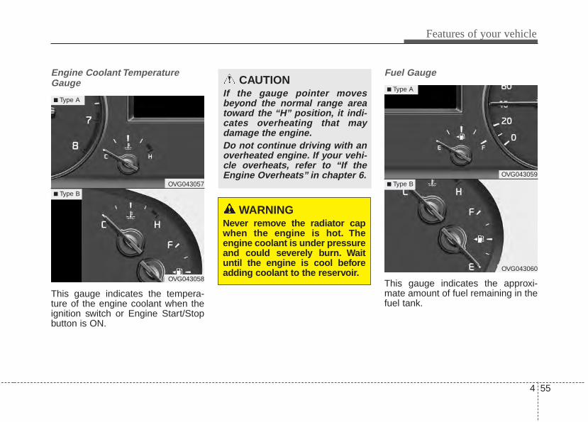
4 55
Features of your vehicle
Engine Coolant TemperatureGauge
This gauge indicates the tempera-ture of the engine coolant when theignition switch or Engine Start/Stopbutton is ON.
Fuel Gauge
This gauge indicates the approxi-mate amount of fuel remaining in thefuel tank.
WARNINGNever remove the radiator capwhen the engine is hot. Theengine coolant is under pressureand could severely burn. Waituntil the engine is cool beforeadding coolant to the reservoir.
CAUTIONIf the gauge pointer movesbeyond the normal range areatoward the “H” position, it indi-cates overheating that maydamage the engine.Do not continue driving with anoverheated engine. If your vehi-cle overheats, refer to “If theEngine Overheats” in chapter 6.
OVG043057
OVG043058
■ Type A
■ Type B
OVG043059
OVG043060
■ Type A
■ Type B
Features of your vehicle
564
✽✽ NOTICE• The fuel tank capacity is given in
chapter 8.• The fuel gauge is supplemented by
a low fuel warning light, whichwill illuminate when the fuel tankis nearly empty.
• On inclines or curves, the fuelgauge pointer may fluctuate or thelow fuel warning light may comeon earlier than usual due to themovement of fuel in the tank.
✽✽ NOTICEFuel display may not be accurate ifyou are filling in sloping places.
WARNING - Fuel GaugeRunning out of fuel can exposevehicle occupants to danger.You must stop and obtain addi-tional fuel as soon as possibleafter the warning light comeson or when the gauge indicatorcomes close to the “E (Empty)”level.
CAUTIONAvoid driving with a extremelylow fuel level. Running out offuel could cause the engine tomisfire damaging the catalyticconverter.
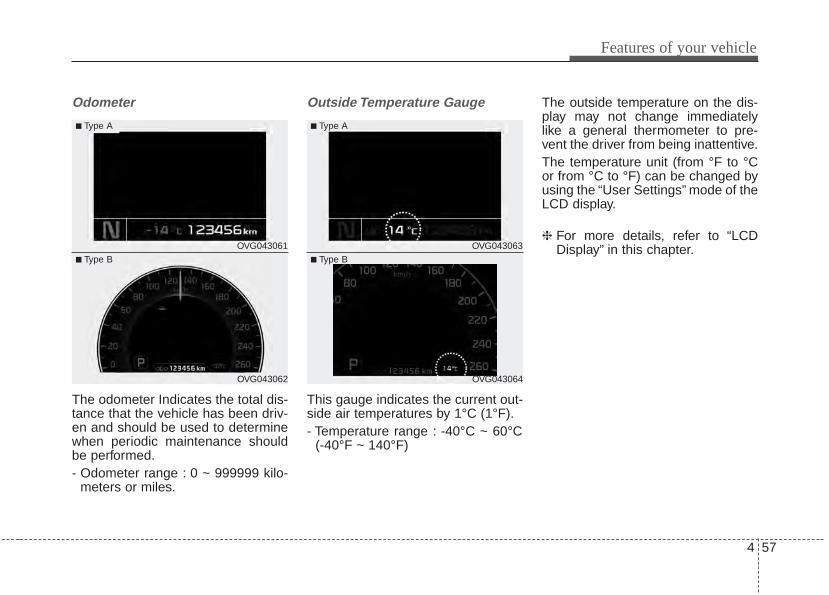
4 57
Features of your vehicle
Odometer
The odometer Indicates the total dis-tance that the vehicle has been driv-en and should be used to determinewhen periodic maintenance shouldbe performed.- Odometer range : 0 ~ 999999 kilo-
meters or miles.
Outside Temperature Gauge
This gauge indicates the current out-side air temperatures by 1°C (1°F).- Temperature range : -40°C ~ 60°C
(-40°F ~ 140°F)
The outside temperature on the dis-play may not change immediatelylike a general thermometer to pre-vent the driver from being inattentive.The temperature unit (from °F to °Cor from °C to °F) can be changed byusing the “User Settings” mode of theLCD display.
❈ For more details, refer to “LCDDisplay” in this chapter.OVG043061
OVG043062
■ Type A
■ Type B
OVG043063
OVG043064
■ Type A
■ Type B
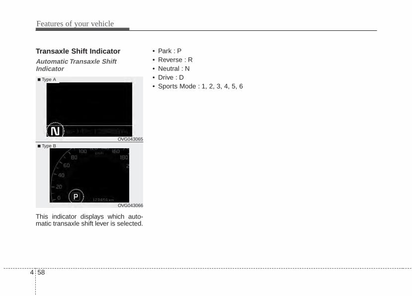
Features of your vehicle
584
Transaxle Shift IndicatorAutomatic Transaxle ShiftIndicator
This indicator displays which auto-matic transaxle shift lever is selected.
• Park : P• Reverse : R• Neutral : N• Drive : D • Sports Mode : 1, 2, 3, 4, 5, 6
OVG043065
OVG043066
■ Type A
■ Type B
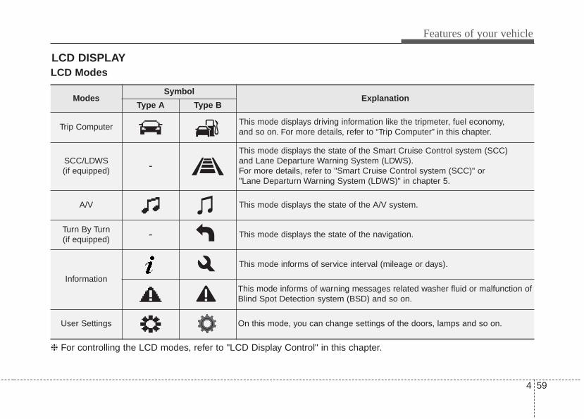
4 59
Features of your vehicle
LCD ModesLCD DISPLAY
Modes Symbol
ExplanationType A Type B
Trip Computer This mode displays driving information like the tripmeter, fuel economy, and so on. For more details, refer to “Trip Computer” in this chapter.
SCC/LDWS(if equipped) -
This mode displays the state of the Smart Cruise Control system (SCC) and Lane Departure Warning System (LDWS).For more details, refer to "Smart Cruise Control system (SCC)" or "Lane Departurn Warning System (LDWS)" in chapter 5.
A/V This mode displays the state of the A/V system.
Turn By Turn(if equipped) - This mode displays the state of the navigation.
Information
This mode informs of service interval (mileage or days).
This mode informs of warning messages related washer fluid or malfunction ofBlind Spot Detection system (BSD) and so on.
User Settings On this mode, you can change settings of the doors, lamps and so on.
❈ For controlling the LCD modes, refer to "LCD Display Control" in this chapter.
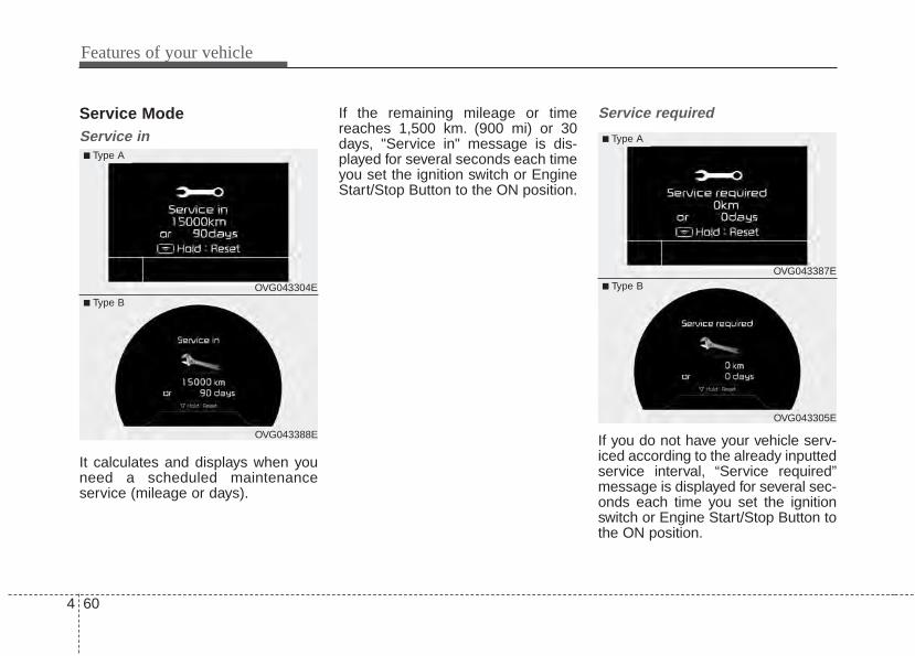
Features of your vehicle
604
Service ModeService in
It calculates and displays when youneed a scheduled maintenanceservice (mileage or days).
If the remaining mileage or timereaches 1,500 km. (900 mi) or 30days, "Service in" message is dis-played for several seconds each timeyou set the ignition switch or EngineStart/Stop Button to the ON position.
Service required
If you do not have your vehicle serv-iced according to the already inputtedservice interval, “Service required”message is displayed for several sec-onds each time you set the ignitionswitch or Engine Start/Stop Button tothe ON position.
OVG043304E
OVG043388E
■ Type A
■ Type B
OVG043387E
OVG043305E
■ Type A
■ Type B
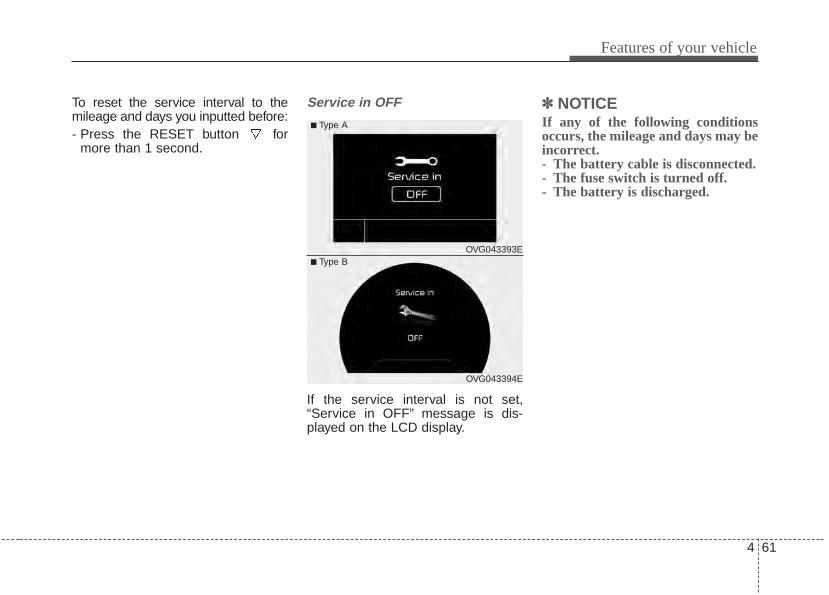
4 61
Features of your vehicle
To reset the service interval to themileage and days you inputted before:- Press the RESET button for
more than 1 second.
Service in OFF
If the service interval is not set,“Service in OFF” message is dis-played on the LCD display.
✽✽ NOTICE If any of the following conditionsoccurs, the mileage and days may beincorrect.- The battery cable is disconnected.- The fuse switch is turned off.- The battery is discharged.
OVG043394E
■ Type A
■ Type BOVG043393E
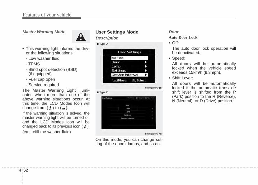
Features of your vehicle
624
Master Warning Mode
• This warning light informs the driv-er the following situations- Low washer fluid- TPMS- Blind spot detection (BSD)
(if equipped)- Fuel cap open- Service required
The Master Warning Light illumi-nates when more than one of theabove warning situations occur. Atthis time, the LCD Modes Icon willchange from ( ) to ( ).If the warning situation is solved, themaster warning light will be turned offand the LCD Modes Icon will bechanged back to its previous icon ( ).(ex : refill the washer fluid)
User Settings ModeDescription
On this mode, you can change set-ting of the doors, lamps, and so on.
DoorAuto Door Lock• Off:
The auto door lock operation willbe deactivated.
• Speed:All doors will be automaticallylocked when the vehicle speedexceeds 15km/h (9.3mph).
• Shift Lever:All doors will be automaticallylocked if the automatic transaxleshift lever is shifted from the P(Park) position to the R (Reverse),N (Neutral), or D (Drive) position.
OVG043309E
■ Type A
■ Type BOVG043308E
4 63
Features of your vehicle
Auto Door Unlock• Off:
The auto door unlock operation willbe canceled.
• Key Out or Power Off:All doors will be automaticallyunlocked when the ignition key isremoved from ignition switch orEngine Start/Stop Button is set tothe OFF position.
• Shift Lever:All doors will be automaticallyunlocked if the automatic transaxleshift lever is shifted to the P (Park)position.
Two Press Unlock• Off:
The two press unlock function willbe deactivated.Therefore, all doorswill unlock if the door is unlocked.
• On:The driver’s door will unlock if thedoor is unlocked. When the door isunlocked again within 4 seconds,all doors will unlock.
Lock/Unlock sound• Off:
The Lock/Unlock sound operationwill be deactivated.
• On:When you locking (or unlocking)the door by pressing the lock (orunlock) button on the transmitter ordoor out handle, the confirm soundwill operate.
Horn Feedback • Off:
The Horn feedback operation willbe deactivated.
• On:After locking the door by pressingthe lock button on the transmitter, ifyou press the lock button againwithin 4 seconds, the warningsound will operate once to indicatethat all doors are locked.
Features of your vehicle
644
LampOne touch turn lampIf this item is checked, the lanechange signals will blink 3, 5 or 7times when the turn signal lever ismoved slightly.
Head Lamp DelayIf this item is checked, the headlampdelay and headlamp welcome func-tion will be activated.
Welcome Light (if equipped)If this item is checked, the welcomelight function of the pocket lamp willbe activated.
SettingsTemperature UnitConvert the temperature unit from °Cto °F or from °F to °C.
Speed Unit (for type B cluster)Convert the speedometer unit km/hto MPH or MPH to km/hAt this time MPH or km/h unit dis-played in the upper-right corner.
Speedometer Size (for type B cluster)Adjust the size of the numbers on thecluster you prefer (normal or large)
AVG Fuel Eco Reset• Auto Reset:
The average fuel economy willreset automatically when refueling.
• Manual Reset:The average fuel economy will notreset automatically whenever refu-eling.
For more details, refer to “TripComputer” in this chapter.
Seat Easy Access (if equipped)If this item is checked, the driver’sseat will automatically move forwardor rearward for the driver to enter orexit the vehicle comfortably.
Steering Easy Access (if equipped)If this item is checked, the steeringwheel will automatically move upwardor downward for driver to enter or exitthe vehicle comfortably.
Welcome SoundIf this item is checked, the welcomesound function will be activated.
Steering PositionIf this item is checked, the warningfunction regarding the steering wheelalignment will be activated.For more details, refer to "WarningMessages" in this chapter.
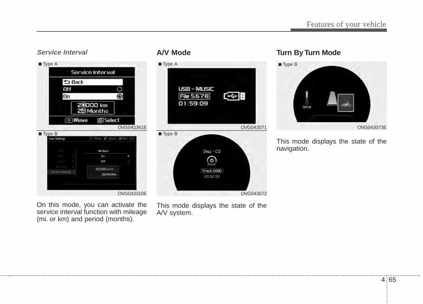
4 65
Features of your vehicle
Service Interval
On this mode, you can activate theservice interval function with mileage(mi. or km) and period (months).
A/V Mode
This mode displays the state of theA/V system.
Turn By Turn Mode
This mode displays the state of thenavigation.
OVG043072
■ Type A
■ Type BOVG043071 OVG043073E
■ Type B
OVG043310E
■ Type A
■ Type BOVG043361E
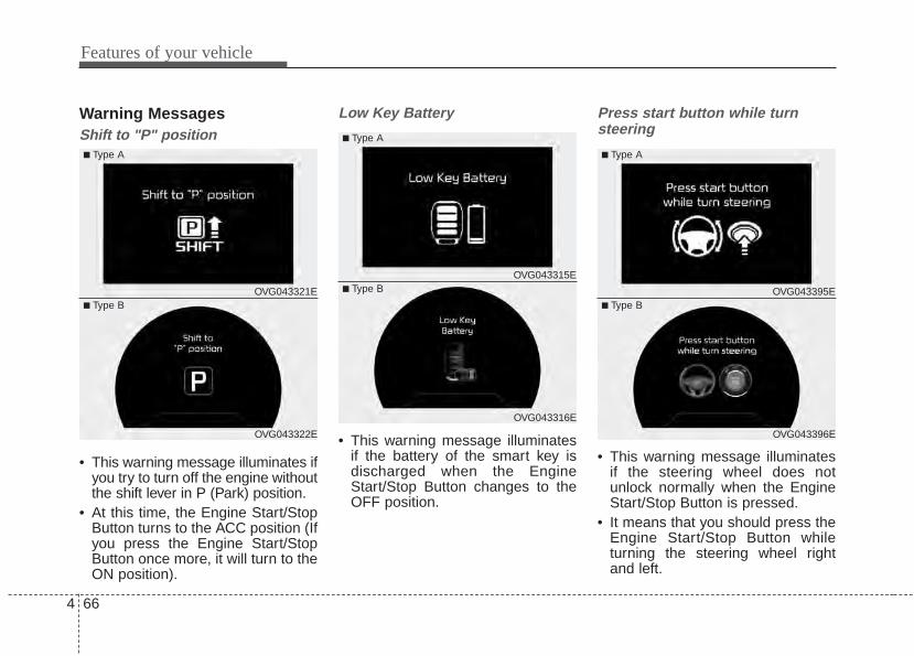
Features of your vehicle
664
Warning MessagesShift to "P" position
• This warning message illuminates ifyou try to turn off the engine withoutthe shift lever in P (Park) position.
• At this time, the Engine Start/StopButton turns to the ACC position (Ifyou press the Engine Start/StopButton once more, it will turn to theON position).
Low Key Battery
• This warning message illuminatesif the battery of the smart key isdischarged when the EngineStart/Stop Button changes to theOFF position.
Press start button while turnsteering
• This warning message illuminatesif the steering wheel does notunlock normally when the EngineStart/Stop Button is pressed.
• It means that you should press theEngine Start/Stop Button whileturning the steering wheel rightand left.
OVG043322E
■ Type A
■ Type BOVG043321E
OVG043316E
■ Type A
■ Type BOVG043315E
OVG043396E
■ Type A
■ Type BOVG043395E
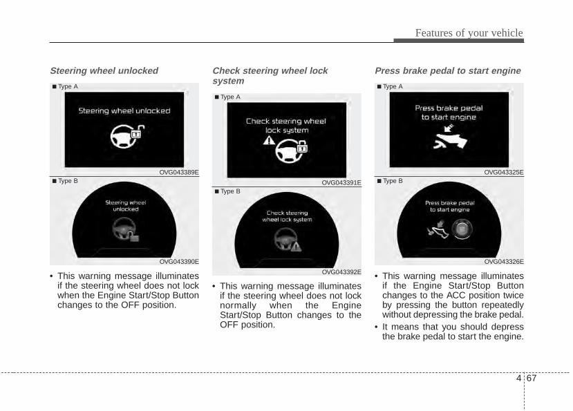
4 67
Features of your vehicle
Steering wheel unlocked
• This warning message illuminatesif the steering wheel does not lockwhen the Engine Start/Stop Buttonchanges to the OFF position.
Check steering wheel lock system
• This warning message illuminatesif the steering wheel does not locknormally when the EngineStart/Stop Button changes to theOFF position.
Press brake pedal to start engine
• This warning message illuminatesif the Engine Start/Stop Buttonchanges to the ACC position twiceby pressing the button repeatedlywithout depressing the brake pedal.
• It means that you should depressthe brake pedal to start the engine.
OVG043390E
■ Type A
■ Type BOVG043389E
OVG043392E
■ Type A
■ Type BOVG043391E
OVG043326E
■ Type A
■ Type BOVG043325E

Features of your vehicle
684
Key not in vehicle
• This warning message illuminatesif the smart key is not in the vehiclewhen you press the EngineStart/Stop Button.
• It means that you should alwayshave the smart key with you.
Key not detected
• This warning message illuminatesif the smart key is not detectedwhen you press the EngineStart/Stop Button.
Press start button again
• This warning message illuminatesif you can not operate the EngineStart/Stop Button when there is aproblem with the Engine Start/StopButton system.
• It means that you could start theengine by pressing the EngineStart/ Stop Button once more.
OVG043312E
■ Type A
■ Type BOVG043311E
OVG043314E
■ Type A
■ Type BOVG043313E
OVG043318E
■ Type A
■ Type BOVG043317E
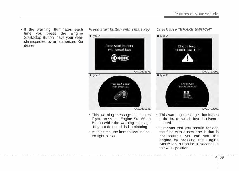
4 69
Features of your vehicle
• If the warning illuminates eachtime you press the EngineStart/Stop Button, have your vehi-cle inspected by an authorized Kiadealer.
Press start button with smart key
• This warning message illuminatesif you press the Engine Start/StopButton while the warning message“Key not detected” is illuminating.
• At this time, the immobilizer indica-tor light blinks.
Check fuse "BRAKE SWITCH"
• This warning message illuminatesif the brake switch fuse is discon-nected.
• It means that you should replacethe fuse with a new one. If that isnot possible, you can start theengine by pressing the EngineStart/Stop Button for 10 seconds inthe ACC position.
OVG043320E
■ Type A
■ Type BOVG043319E
OVG043330E
■ Type A
■ Type BOVG043329E
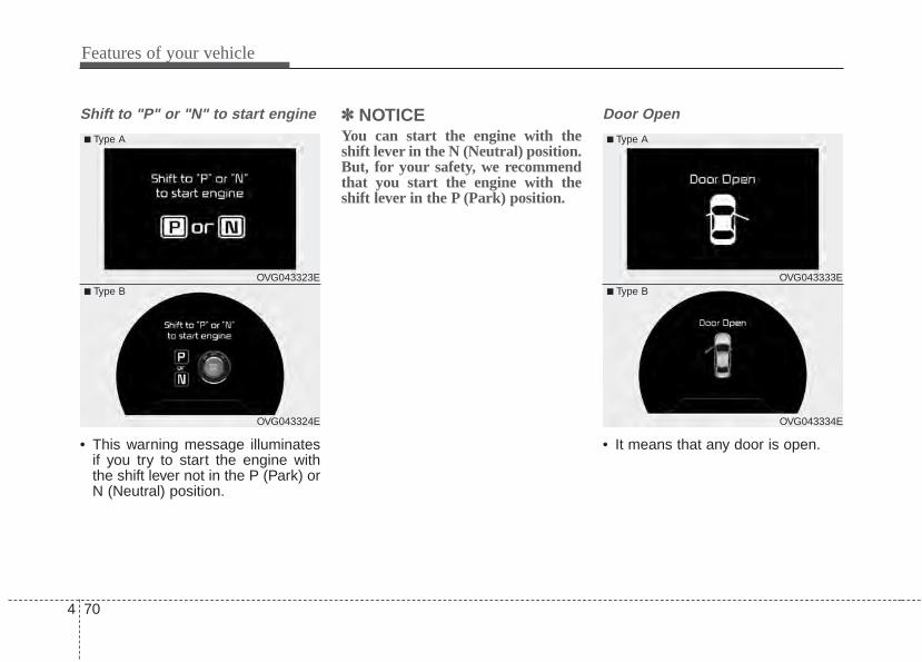
Features of your vehicle
704
Shift to "P" or "N" to start engine
• This warning message illuminatesif you try to start the engine withthe shift lever not in the P (Park) orN (Neutral) position.
✽✽ NOTICEYou can start the engine with theshift lever in the N (Neutral) position.But, for your safety, we recommendthat you start the engine with theshift lever in the P (Park) position.
Door Open
• It means that any door is open.
OVG043324E
■ Type A
■ Type BOVG043323E
OVG043334E
■ Type A
■ Type BOVG043333E
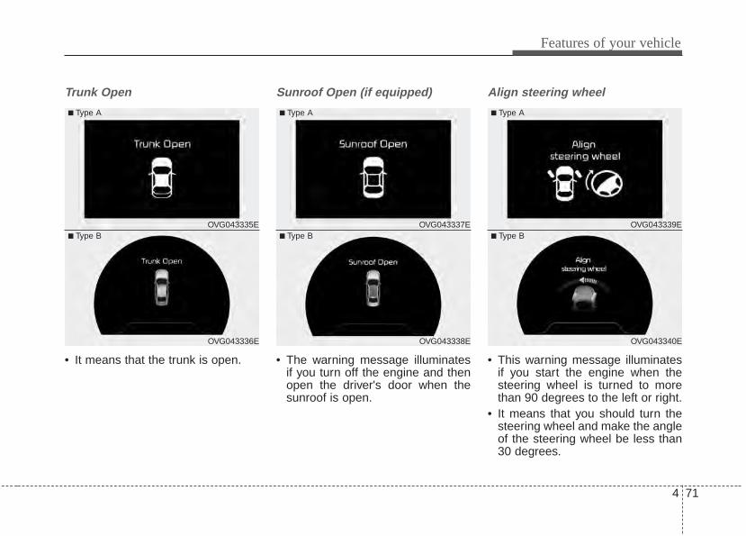
4 71
Features of your vehicle
Trunk Open
• It means that the trunk is open.
Sunroof Open (if equipped)
• The warning message illuminatesif you turn off the engine and thenopen the driver's door when thesunroof is open.
Align steering wheel
• This warning message illuminatesif you start the engine when thesteering wheel is turned to morethan 90 degrees to the left or right.
• It means that you should turn thesteering wheel and make the angleof the steering wheel be less than30 degrees.
OVG043336E
■ Type A
■ Type BOVG043335E
OVG043338E
■ Type A
■ Type BOVG043337E
OVG043340E
■ Type A
■ Type BOVG043339E
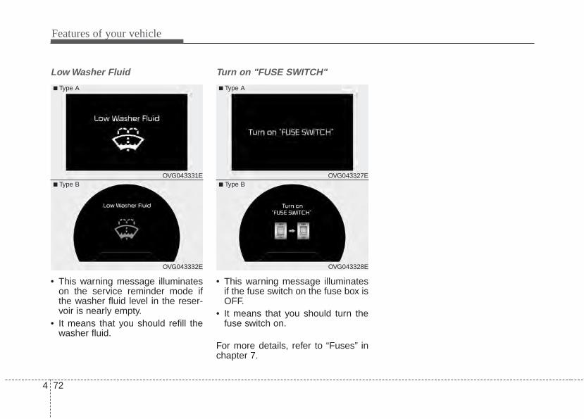
Features of your vehicle
724
Low Washer Fluid
• This warning message illuminateson the service reminder mode ifthe washer fluid level in the reser-voir is nearly empty.
• It means that you should refill thewasher fluid.
Turn on "FUSE SWITCH"
• This warning message illuminatesif the fuse switch on the fuse box isOFF.
• It means that you should turn thefuse switch on.
For more details, refer to “Fuses” inchapter 7.
OVG043332E
■ Type A
■ Type BOVG043331E
OVG043328E
■ Type A
■ Type BOVG043327E
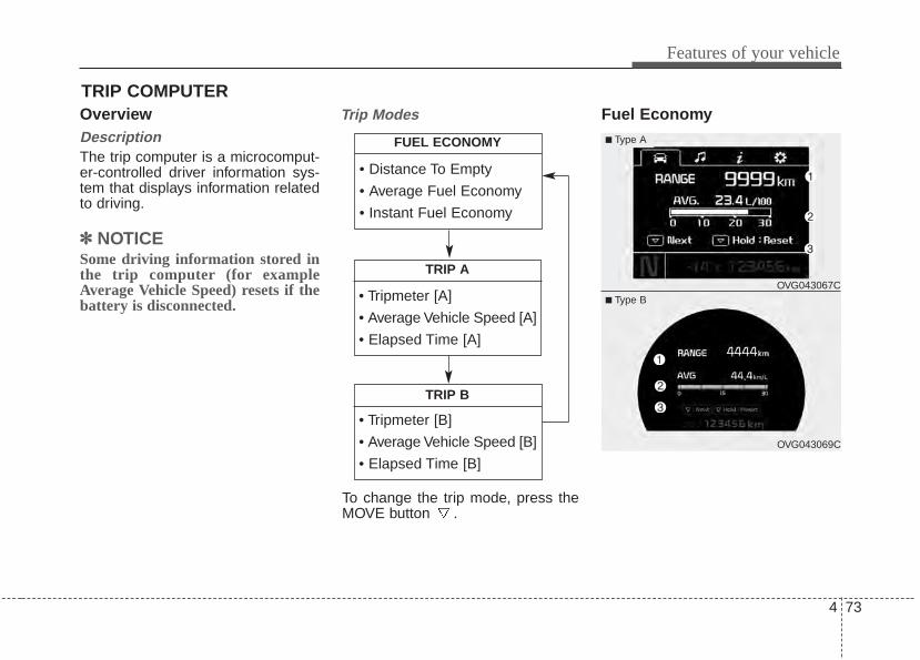
4 73
Features of your vehicle
OverviewDescriptionThe trip computer is a microcomput-er-controlled driver information sys-tem that displays information relatedto driving.
✽✽ NOTICESome driving information stored inthe trip computer (for exampleAverage Vehicle Speed) resets if thebattery is disconnected.
Trip Modes Fuel EconomyTRIP COMPUTER
• Tripmeter [A]
• Average Vehicle Speed [A]
• Elapsed Time [A]
TRIP A
• Tripmeter [B]
• Average Vehicle Speed [B]
• Elapsed Time [B]
TRIP B
• Distance To Empty
• Average Fuel Economy
• Instant Fuel Economy
FUEL ECONOMY
To change the trip mode, press theMOVE button .
■ Type A
OVG043067C
OVG043069C
■ Type B
Features of your vehicle
744
Range (1)• The range is the estimated dis-
tance the vehicle can be drivenwith the remaining fuel.- Distance range : 50 ~ 9999 km or
30 ~ 9999 mi.• If the estimated distance is below
50 km. (30 mi), the trip computer willdisplay “---” as range.
✽✽ NOTICE• If the vehicle is not on level ground
or the battery power has beeninterrupted, the range functionmay not operate correctly.
• The range may differ from theactual driving distance as it is anestimate of the available drivingdistance.
• The trip computer may not registeradditional fuel if less than 6 liters(1.6 gallons) of fuel are added to thevehicle.
• The fuel economy and range mayvary significantly based on drivingconditions, driving habits, and con-dition of the vehicle.
Average Fuel Economy (2)• The average fuel economy is calcu-
lated by the total driving distanceand fuel consumption since the lastaverage fuel economy reset.- Fuel economy range: L/100km or
0.0 ~ 99.9 MPG• The average fuel economy can be
reset both manually and automati-cally.
Manual resetTo clear the average fuel economymanually, press the RESET button on the steering wheel for more than 1second when the average fuel econo-my is displayed.
Automatic resetTo make the average fuel economybe reset automatically whenever refu-eling, select the “Auto Reset” mode inUser Setting menu of the LCD display(Refer to “LCD Display”).Under “Auto Reset” mode, the aver-age fuel economy will be cleared tozero (---) when the vehicle speedexceeds 1 km/h after refueling morethan 1.6 gallons (6 liters).
✽✽ NOTICEThe average fuel economy is not dis-played for more accurate calculationif the vehicle does not drive morethan 300 meters (0.19 miles) sincethe Engine Start/Stop button isturned to ON.
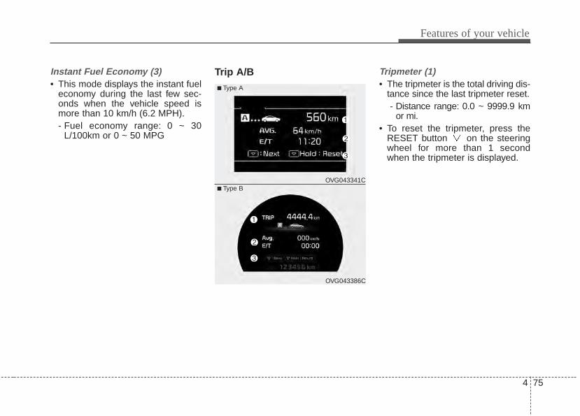
4 75
Features of your vehicle
Instant Fuel Economy (3)• This mode displays the instant fuel
economy during the last few sec-onds when the vehicle speed ismore than 10 km/h (6.2 MPH).- Fuel economy range: 0 ~ 30
L/100km or 0 ~ 50 MPG
Trip A/B Tripmeter (1)• The tripmeter is the total driving dis-
tance since the last tripmeter reset.- Distance range: 0.0 ~ 9999.9 km
or mi.• To reset the tripmeter, press the
RESET button on the steeringwheel for more than 1 secondwhen the tripmeter is displayed.
■ Type A
OVG043341C
OVG043386C
■ Type B
Features of your vehicle
764
Average Vehicle Speed (2)• The average vehicle speed is cal-
culated by the total driving dis-tance and driving time since thelast average vehicle speed reset.- Speed range: 0 ~ 999 km/h or MPH
• To reset the average vehicle speed,press the RESET button on thesteering wheel for more than 1 sec-ond when the average vehiclespeed is displayed.
✽✽ NOTICE• The average vehicle speed is not dis-
played if the driving distance is lessthan 300 meters (0.19 miles) sincethe Engine Start/Stop button isturned to ON.
• Even if the vehicle is not in motion,the average vehicle speed keepsgoing while the engine is running.
Elapsed Time (3)• The elapsed time is the total driv-
ing time since the last elapsed timereset.- Time range (hh:mm): 00:00 ~ 99:59
• To reset the elapsed time, press theRESET button on the steeringwheel for more than 1 second whenthe elapsed time is displayed.
✽✽ NOTICEEven if the vehicle is not in motion,the elapsed time keeps going whilethe engine is running.
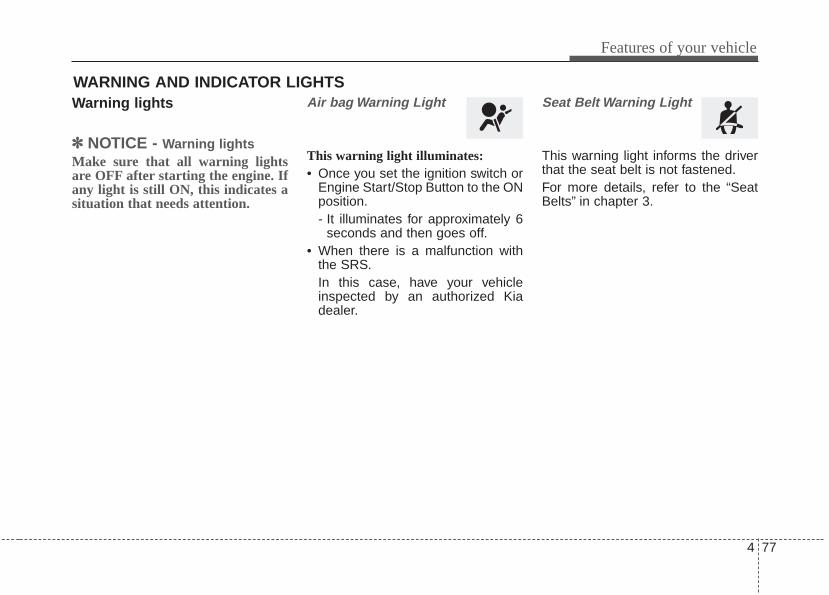
4 77
Features of your vehicle
Warning lights
✽✽ NOTICE - Warning lightsMake sure that all warning lightsare OFF after starting the engine. Ifany light is still ON, this indicates asituation that needs attention.
Air bag Warning Light
This warning light illuminates:• Once you set the ignition switch or
Engine Start/Stop Button to the ONposition.- It illuminates for approximately 6
seconds and then goes off.• When there is a malfunction with
the SRS.In this case, have your vehicleinspected by an authorized Kiadealer.
Seat Belt Warning Light
This warning light informs the driverthat the seat belt is not fastened.For more details, refer to the “SeatBelts” in chapter 3.
WARNING AND INDICATOR LIGHTS
Features of your vehicle
784
Parking Brake & BrakeFluid Warning Light
This warning light illuminates:• Once you set the ignition switch or
Engine Start/Stop Button to the ONposition.- It illuminates for approximately 3
seconds- It remains on if the parking brake
is applied.• When the parking brake is applied.• When the brake fluid level in the
reservoir is low.- If the warning light illuminates
with the parking brake released, itindicates the brake fluid level inreservoir is low.
If the brake fluid level in the reservoiris low:1. Drive carefully to the nearest safe
location and stop your vehicle.2. With the engine stopped, check the
brake fluid level immediately and addfluid as required (For more details,refer to “Brake Fluid” in chapter 7).Then check all brake componentsfor fluid leaks. If any leaks in thebrake system is still found, thewarning light remains on, or thebrakes do not operate properly, donot drive the vehicle.In this case, have your vehicletowed to an authorized Kia dealerand inspected.
Dual-diagonal braking systemYour vehicle is equipped with dual-diagonal braking systems. Thismeans you still have braking on twowheels even if one of the dual sys-tems should fail.With only one of the dual systemsworking, more than normal pedaltravel and greater pedal pressure arerequired to stop the vehicle.Also, the vehicle will not stop in asshort a distance with only a portionof the brake system working.If the brakes fail while you are driv-ing, shift to a lower gear for addition-al engine braking and stop the vehi-cle as soon as it is safe to do so.
4 79
Features of your vehicle
Anti-lock Brake System(ABS) Warning Light
This warning light illuminates:• Once you set the ignition switch or
Engine Start/Stop Button to the ONposition.- It illuminates for approximately 3
seconds and then goes off.• When there is a malfunction with
the ABS (The normal braking sys-tem will still be operational withoutthe assistance of the anti-lockbrake system).In this case, have your vehicleinspected by an authorized Kiadealer.
ElectronicBrake forceDistribution(EBD) SystemWarning LightThese two warning lights illuminate atthe same time while driving:• When the ABS and regular brake
system may not work normally.In this case, have your vehicleinspected by an authorized Kiadealer.
WARNING - Parking Brake& Brake Fluid Warning Light
Driving the vehicle with a warn-ing light ON is dangerous. If theParking Brake & Brake FluidWarning Light illuminates withthe parking brake released, itindicates that the brake fluidlevel is low.In this case, have your vehicleinspected by an authorized Kiadealer.
WARNING - ElectronicBrake force Distribution(EBD) System Warning Light
When both ABS and ParkingBrake & Brake Fluid WarningLights are on, the brake systemwill not work normally and youmay experience an unexpectedand dangerous situation duringsudden braking.In this case, avoid high speeddriving and abrupt braking.Have your vehicle inspected byan authorized Kia dealer assoon as possible.
Features of your vehicle
804
✽✽ NOTICE - Electronic Brakeforce Distribution(EBD) SystemWarning Light
When the ABS Warning Light is onor both ABS and Parking Brake &Brake Fluid Warning Lights are on,the speedometer, odometer, or trip-meter may not work. Also, the EPSWarning Light may illuminate andthe steering effort may increase ordecrease.In this case, have your vehicle inspect-ed by an authorized Kia dealer assoon as possible.
Electronic PowerSteering (EPS) WarningLight
This warning light illuminates:• Once you set the ignition switch or
Engine Start/Stop Button to the ONposition.- It remains on until the engine is
started.• When there is a malfunction with
the EPS.In this case, have your vehicleinspected by an authorized Kiadealer.
Malfunction IndicatorLamp (MIL)
This warning light illuminates:• Once you set the ignition switch or
Engine Start/Stop Button to the ONposition.- It remains on until the engine is
started.• When there is a malfunction with
the emission control system.In this case, have your vehicleinspected by an authorized Kiadealer.
CAUTION - MalfunctionIndicatorLamp (MIL)
Driving with the MalfunctionIndicator Lamp (MIL) on maycause damage to the emissioncontrol systems which couldeffect drivability and/or fueleconomy.
4 81
Features of your vehicle
Charging SystemWarning Light
This warning light illuminates:• Once you set the ignition switch or
Engine Start/Stop Button to the ONposition.- It remains on until the engine is
started.• When there is a malfunction with
either the alternator or electricalcharging system.
If there is a malfunction with eitherthe alternator or electrical chargingsystem:1. Drive carefully to the nearest safe
location and stop your vehicle.2. Turn the engine off and check the
alternator drive belt for loosenessor breakage.If the belt is adjusted properly,there may be a problem in theelectrical charging system.In this case, have your vehicleinspected by an authorized Kiadealer as soon as possible.
CAUTION - GasolineEngine
If the Malfunction IndicatorLamp (MIL) illuminates, poten-tial catalytic converter damageis possible which could result inloss of engine power.In this case, have your vehicleinspected by an authorized Kiadealer as soon as possible.
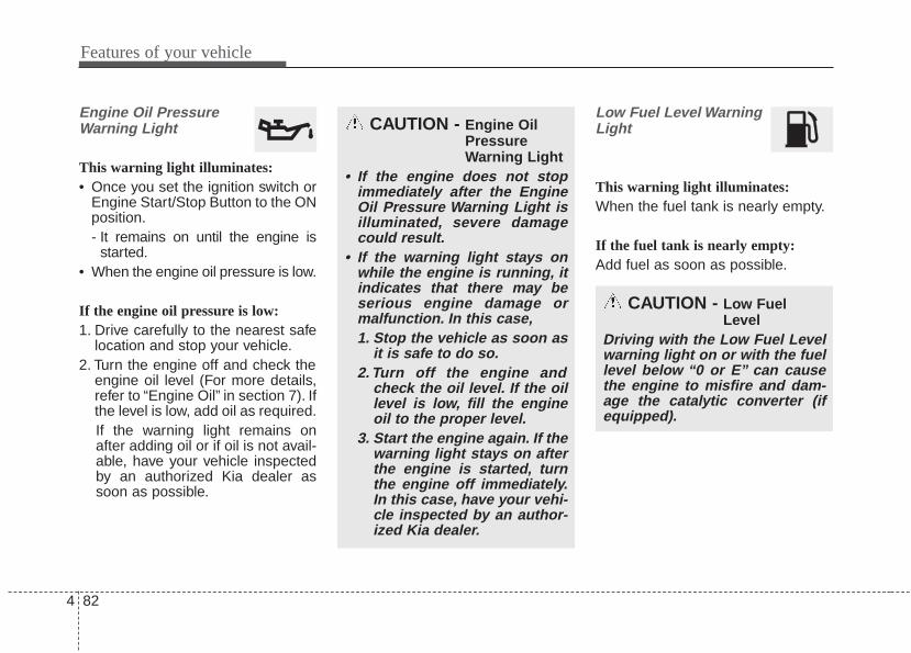
Features of your vehicle
824
Engine Oil PressureWarning Light
This warning light illuminates:• Once you set the ignition switch or
Engine Start/Stop Button to the ONposition.- It remains on until the engine is
started.• When the engine oil pressure is low.
If the engine oil pressure is low:1. Drive carefully to the nearest safe
location and stop your vehicle.2. Turn the engine off and check the
engine oil level (For more details,refer to “Engine Oil” in section 7). Ifthe level is low, add oil as required.If the warning light remains onafter adding oil or if oil is not avail-able, have your vehicle inspectedby an authorized Kia dealer assoon as possible.
Low Fuel Level WarningLight
This warning light illuminates:When the fuel tank is nearly empty.
If the fuel tank is nearly empty:Add fuel as soon as possible.
CAUTION - Engine OilPressureWarning Light
• If the engine does not stopimmediately after the EngineOil Pressure Warning Light isilluminated, severe damagecould result.
• If the warning light stays onwhile the engine is running, itindicates that there may beserious engine damage ormalfunction. In this case,1. Stop the vehicle as soon as
it is safe to do so.2. Turn off the engine and
check the oil level. If the oillevel is low, fill the engineoil to the proper level.
3. Start the engine again. If thewarning light stays on afterthe engine is started, turnthe engine off immediately.In this case, have your vehi-cle inspected by an author-ized Kia dealer.
CAUTION - Low FuelLevel
Driving with the Low Fuel Levelwarning light on or with the fuellevel below “0 or E” can causethe engine to misfire and dam-age the catalytic converter (ifequipped).
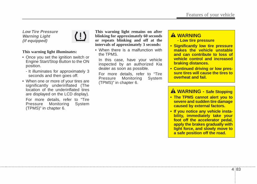
4 83
Features of your vehicle
Low Tire PressureWarning Light(if equipped)
This warning light illuminates:• Once you set the ignition switch or
Engine Start/Stop Button to the ONposition.- It illuminates for approximately 3
seconds and then goes off.• When one or more of your tires are
significantly underinflated (Thelocation of the underinflated tiresare displayed on the LCD display).For more details, refer to “TirePressure Monitoring System(TPMS)” in chapter 6.
This warning light remains on afterblinking for approximately 60 secondsor repeats blinking and off at theintervals of approximately 3 seconds:• When there is a malfunction with
the TPMS.In this case, have your vehicleinspected by an authorized Kiadealer as soon as possible.For more details, refer to “TirePressure Monitoring System(TPMS)” in chapter 6.
WARNING - Safe Stopping• The TPMS cannot alert you to
severe and sudden tire damagecaused by external factors.
• If you notice any vehicle insta-bility, immediately take yourfoot off the accelerator pedal,apply the brakes gradually withlight force, and slowly move toa safe position off the road.
WARNING - Low tire pressure
• Significantly low tire pressuremakes the vehicle unstableand can contribute to loss ofvehicle control and increasedbraking distances.
• Continued driving or low pres-sure tires will cause the tires tooverheat and fail.
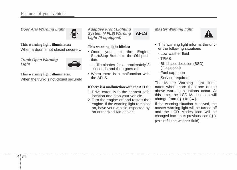
Features of your vehicle
844
Door Ajar Warning Light
This warning light illuminates:When a door is not closed securely.
Trunk Open WarningLight
This warning light illuminates:When the trunk is not closed securely.
Adaptive Front LightingSystem (AFLS) WarningLight (if equipped)
This warning light blinks:• Once you set the Engine
Start/Stop Button to the ON posi-tion.- It illuminates for approximately 3
seconds and then goes off.• When there is a malfunction with
the AFLS.
If there is a malfunction with the AFLS:1. Drive carefully to the nearest safe
location and stop your vehicle.2. Turn the engine off and restart the
engine. If the warning light remainson, have your vehicle inspected byan authorized Kia dealer.
Master Warning light
• This warning light informs the driv-er the following situations- Low washer fluid- TPMS- Blind spot detection (BSD)
(if equipped)- Fuel cap open- Service required
The Master Warning Light illumi-nates when more than one of theabove warning situations occur. Atthis time, the LCD Modes Icon willchange from ( ) to ( ).If the warning situation is solved, themaster warning light will be turned offand the LCD Modes Icon will bechanged back to its previous icon ( ).(ex : refill the washer fluid)
AFLS
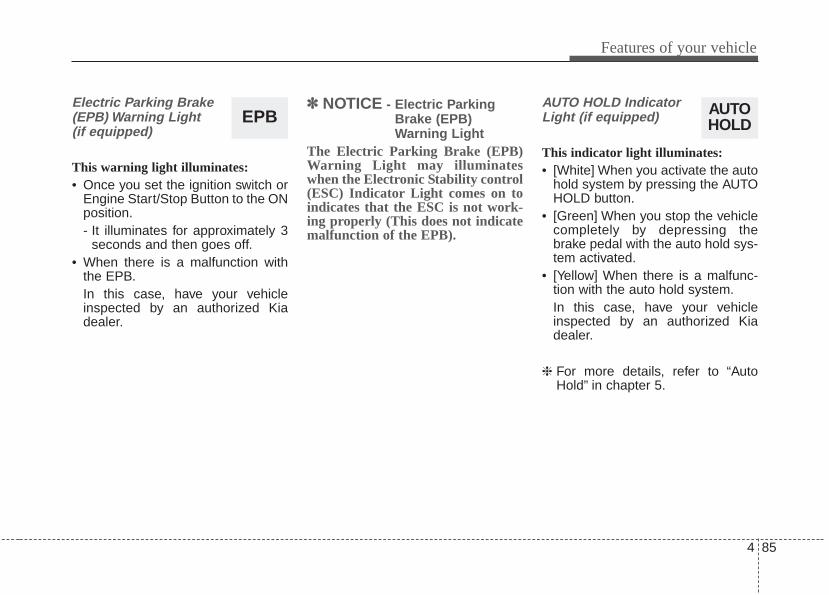
4 85
Features of your vehicle
Electric Parking Brake(EPB) Warning Light(if equipped)
This warning light illuminates:• Once you set the ignition switch or
Engine Start/Stop Button to the ONposition.- It illuminates for approximately 3
seconds and then goes off.• When there is a malfunction with
the EPB.In this case, have your vehicleinspected by an authorized Kiadealer.
✽✽ NOTICE - Electric ParkingBrake (EPB)Warning Light
The Electric Parking Brake (EPB)Warning Light may illuminateswhen the Electronic Stability control(ESC) Indicator Light comes on toindicates that the ESC is not work-ing properly (This does not indicatemalfunction of the EPB).
AUTO HOLD IndicatorLight (if equipped)
This indicator light illuminates:• [White] When you activate the auto
hold system by pressing the AUTOHOLD button.
• [Green] When you stop the vehiclecompletely by depressing thebrake pedal with the auto hold sys-tem activated.
• [Yellow] When there is a malfunc-tion with the auto hold system.In this case, have your vehicleinspected by an authorized Kiadealer.
❈ For more details, refer to “AutoHold” in chapter 5.
EPB AUTOHOLD
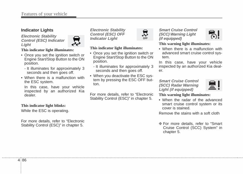
Features of your vehicle
864
Indicator LightsElectronic StabilityControl (ESC) IndicatorLightThis indicator light illuminates:• Once you set the ignition switch or
Engine Start/Stop Button to the ONposition.- It illuminates for approximately 3
seconds and then goes off.• When there is a malfunction with
the ESC system.In this case, have your vehicleinspected by an authorized Kiadealer.
This indicator light blinks:While the ESC is operating.
For more details, refer to “ElectronicStability Control (ESC)” in chapter 5.
Electronic StabilityControl (ESC) OFFIndicator Light
This indicator light illuminates:• Once you set the ignition switch or
Engine Start/Stop Button to the ONposition.- It illuminates for approximately 3
seconds and then goes off.• When you deactivate the ESC sys-
tem by pressing the ESC OFF but-ton.
For more details, refer to “ElectronicStability Control (ESC)” in chapter 5.
Smart Cruise Control(SCC) Warning Light (if equipped)This warning light illuminates:• When there is a malfunction with
advanced smart cruise control sys-tem.
In this case, have your vehicleinspected by an authorized Kia deal-er.
Smart Cruise Control(SCC) Radar WarningLight (if equipped)This warning light illuminates:• When the radar of the advanced
smart cruise control system or itscover is stained.
Remove the stains with a soft cloth
❈ For more details, refer to “SmartCruise Control (SCC) System” inchapter 5.
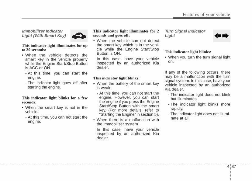
4 87
Features of your vehicle
Immobilizer IndicatorLight (With Smart Key)
This indicator light illuminates for upto 30 seconds:• When the vehicle detects the
smart key in the vehicle properlywhile the Engine Start/Stop Buttonis ACC or ON.- At this time, you can start the
engine.- The indicator light goes off after
starting the engine.
This indicator light blinks for a fewseconds:• When the smart key is not in the
vehicle.- At this time, you can not start the
engine.
This indicator light illuminates for 2seconds and goes off:• When the vehicle can not detect
the smart key which is in the vehi-cle while the Engine Start/StopButton is ON.In this case, have your vehicleinspected by an authorized Kiadealer.
This indicator light blinks:• When the battery of the smart key
is weak.- At this time, you can not start the
engine. However, you can startthe engine if you press the EngineStart/Stop Button with the smartkey. (For more details, refer to“Starting the Engine” in section 5).
• When there is a malfunction withthe immobilizer system.In this case, have your vehicleinspected by an authorized Kiadealer.
Turn Signal IndicatorLight
This indicator light blinks:• When you turn the turn signal light
on.
If any of the following occurs, theremay be a malfunction with the turnsignal system. In this case, have yourvehicle inspected by an authorizedKia dealer.
- The indicator light does not blinkbut illuminates.
- The indicator light blinks morerapidly.
- The indicator light does not illumi-nate at all.

Features of your vehicle
884
High Beam IndicatorLight
This indicator light illuminates:• When the headlights are on and in
the high beam position• When the turn signal lever is pulled
into the Flash-to-Pass position.
Light ON Indicator Light
This indicator light illuminates:• When the tail lights or headlights
are on.
Front Fog IndicatorLight
This indicator light illuminates:• When the front fog lights are on.
Washer Fluid WarningLight
This warning light illuminates:• When the washer fluid level in the
reservoir is nearly empty.In this case, you should refill thewasher fluid.
Cruise Indicator Light
This indicator light illuminates:• When the cruise control system is
enabled.
For more details, refer to “CruiseControl System” in chapter 5.
CRUISE
4 89
Features of your vehicle
Cruise SET IndicatorLight
This indicator light illuminates:• When the cruise control speed is set.
For more details, refer to “CruiseControl System” in chapter 5.
SET
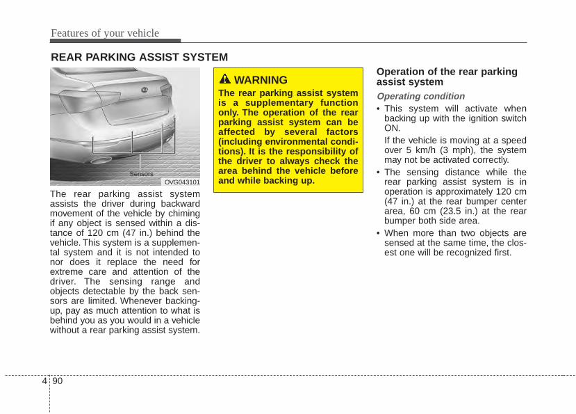
Features of your vehicle
904
The rear parking assist systemassists the driver during backwardmovement of the vehicle by chimingif any object is sensed within a dis-tance of 120 cm (47 in.) behind thevehicle. This system is a supplemen-tal system and it is not intended tonor does it replace the need forextreme care and attention of thedriver. The sensing range andobjects detectable by the back sen-sors are limited. Whenever backing-up, pay as much attention to what isbehind you as you would in a vehiclewithout a rear parking assist system.
Operation of the rear parkingassist systemOperating condition• This system will activate when
backing up with the ignition switchON.If the vehicle is moving at a speedover 5 km/h (3 mph), the systemmay not be activated correctly.
• The sensing distance while therear parking assist system is inoperation is approximately 120 cm(47 in.) at the rear bumper centerarea, 60 cm (23.5 in.) at the rearbumper both side area.
• When more than two objects aresensed at the same time, the clos-est one will be recognized first.
REAR PARKING ASSIST SYSTEM
OVG043101Sensors
WARNINGThe rear parking assist systemis a supplementary functiononly. The operation of the rearparking assist system can beaffected by several factors(including environmental condi-tions). It is the responsibility ofthe driver to always check thearea behind the vehicle beforeand while backing up.
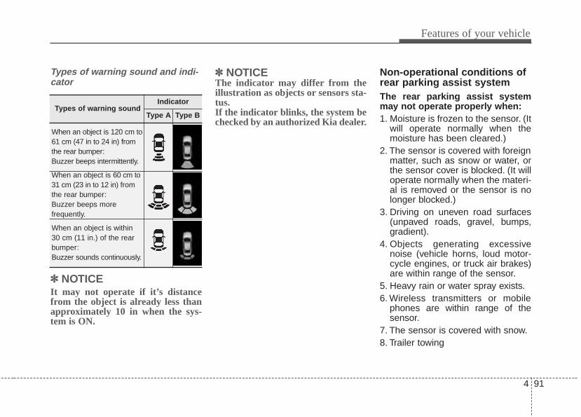
4 91
Features of your vehicle
Types of warning sound and indi-cator
✽✽ NOTICEIt may not operate if it’s distancefrom the object is already less thanapproximately 10 in when the sys-tem is ON.
✽✽ NOTICEThe indicator may differ from theillustration as objects or sensors sta-tus.If the indicator blinks, the system bechecked by an authorized Kia dealer.
Non-operational conditions ofrear parking assist systemThe rear parking assist systemmay not operate properly when:1. Moisture is frozen to the sensor. (It
will operate normally when themoisture has been cleared.)
2. The sensor is covered with foreignmatter, such as snow or water, orthe sensor cover is blocked. (It willoperate normally when the materi-al is removed or the sensor is nolonger blocked.)
3. Driving on uneven road surfaces(unpaved roads, gravel, bumps,gradient).
4. Objects generating excessivenoise (vehicle horns, loud motor-cycle engines, or truck air brakes)are within range of the sensor.
5. Heavy rain or water spray exists.6. Wireless transmitters or mobile
phones are within range of thesensor.
7. The sensor is covered with snow.8. Trailer towing
Types of warning soundIndicator
Type A Type B
When an object is 120 cm to61 cm (47 in to 24 in) fromthe rear bumper:Buzzer beeps intermittently.
When an object is 60 cm to31 cm (23 in to 12 in) fromthe rear bumper:Buzzer beeps more frequently.
When an object is within30 cm (11 in.) of the rearbumper:Buzzer sounds continuously.
Features of your vehicle
924
The detecting range may decreasewhen:1. The sensor is stained with foreign
matter such as snow or water.(The sensing range will return tonormal when removed.)
2. Outside air temperature isextremely hot or cold.
The following objects may not berecognized by the sensor:1. Sharp or slim objects such as
ropes, chains or small poles.2. Objects which tend to absorb the
sensor frequency such as clothes,spongy material or snow.
3. Undetectable objects smaller than1 m (40 in.) in height and narrowerthan 14 cm (6 in.) in diameter.
Rear parking assist systemprecautions• The rear parking assist system
may not sound sequentiallydepending on the speed andshapes of the objects detected.
• The rear parking assist systemmay malfunction if the vehiclebumper height or sensor installa-tion has been modified or dam-aged. Any non-factory installedequipment or accessories mayalso interfere with the sensor per-formance.
• The sensor may not recognizeobjects less than 30 cm (11 in.)from the sensor, or it may sense anincorrect distance. Use caution.
• When the sensor is frozen orstained with snow, dirt, or water,the sensor may be inoperative untilthe stains are removed using a softcloth.
• Do not push, scratch or strike thesensor. Sensor damage couldoccur.
✽✽ NOTICEThis system can only sense objectswithin the range and location of thesensors; It can not detect objects inother areas where sensors are notinstalled. Also, small or slim objects,such as poles or objects locatedbetween sensors may not be detectedby the sensors.Always visually check behind thevehicle when backing up.Be sure to inform any drivers of thevehicle that may be unfamiliar withthe system regarding the systemscapabilities and limitations.

4 93
Features of your vehicle
Self-diagnosisIf you don’t hear an audible warningsound or if the buzzer sounds inter-mittently when shifting the shift leverinto the R (Reverse) position, thismay indicate a malfunction in theparking assist system. If this occurs,the system be checked by an author-ized Kia dealer.
WARNINGYour new vehicle warranty doesnot cover any accidents or dam-age to the vehicle or injuries toits occupants due to a rearparking assist system malfunc-tion. Always drive safely andcautiously.
WARNINGPay close attention when thevehicle is driven close toobjects on the road, particularlypedestrians, and especiallychildren. Be aware that someobjects may not be detected bythe sensors, due to the object’sdistance, size or material, all ofwhich can limit the effective-ness of the sensor. Always per-form a visual inspection tomake sure the vehicle is clear ofall obstructions before movingthe vehicle in any direction.
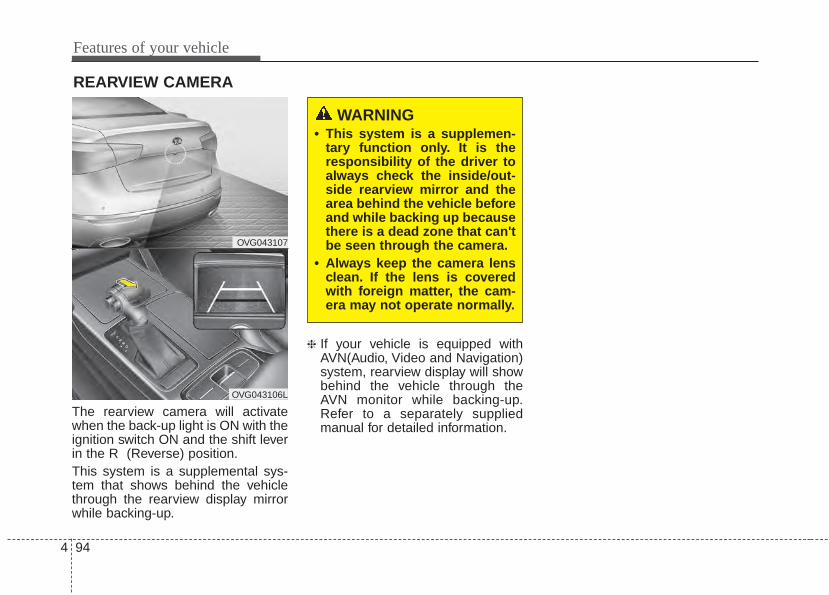
Features of your vehicle
944
The rearview camera will activatewhen the back-up light is ON with theignition switch ON and the shift leverin the R (Reverse) position.This system is a supplemental sys-tem that shows behind the vehiclethrough the rearview display mirrorwhile backing-up.
❈ If your vehicle is equipped withAVN(Audio, Video and Navigation)system, rearview display will showbehind the vehicle through theAVN monitor while backing-up.Refer to a separately suppliedmanual for detailed information.
REARVIEW CAMERA
OVG043107
OVG043106L
WARNING• This system is a supplemen-
tary function only. It is theresponsibility of the driver toalways check the inside/out-side rearview mirror and thearea behind the vehicle beforeand while backing up becausethere is a dead zone that can'tbe seen through the camera.
• Always keep the camera lensclean. If the lens is coveredwith foreign matter, the cam-era may not operate normally.
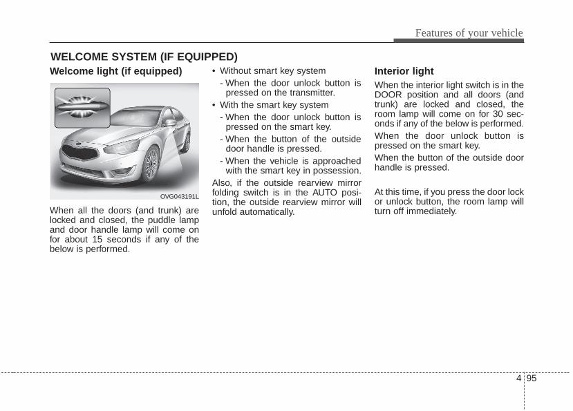
4 95
Features of your vehicle
Welcome light (if equipped)
When all the doors (and trunk) arelocked and closed, the puddle lampand door handle lamp will come onfor about 15 seconds if any of thebelow is performed.
• Without smart key system- When the door unlock button is
pressed on the transmitter.• With the smart key system
- When the door unlock button ispressed on the smart key.
- When the button of the outsidedoor handle is pressed.
- When the vehicle is approachedwith the smart key in possession.
Also, if the outside rearview mirrorfolding switch is in the AUTO posi-tion, the outside rearview mirror willunfold automatically.
Interior light When the interior light switch is in theDOOR position and all doors (andtrunk) are locked and closed, theroom lamp will come on for 30 sec-onds if any of the below is performed.When the door unlock button ispressed on the smart key.When the button of the outside doorhandle is pressed.
At this time, if you press the door lockor unlock button, the room lamp willturn off immediately.
WELCOME SYSTEM (IF EQUIPPED)
OVG043191L
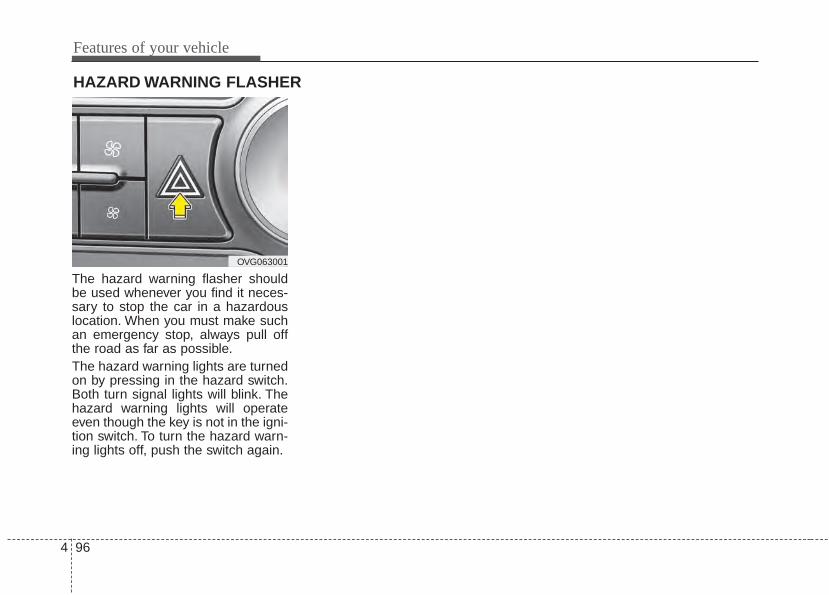
Features of your vehicle
964
The hazard warning flasher shouldbe used whenever you find it neces-sary to stop the car in a hazardouslocation. When you must make suchan emergency stop, always pull offthe road as far as possible.The hazard warning lights are turnedon by pressing in the hazard switch.Both turn signal lights will blink. Thehazard warning lights will operateeven though the key is not in the igni-tion switch. To turn the hazard warn-ing lights off, push the switch again.
HAZARD WARNING FLASHER
OVG063001
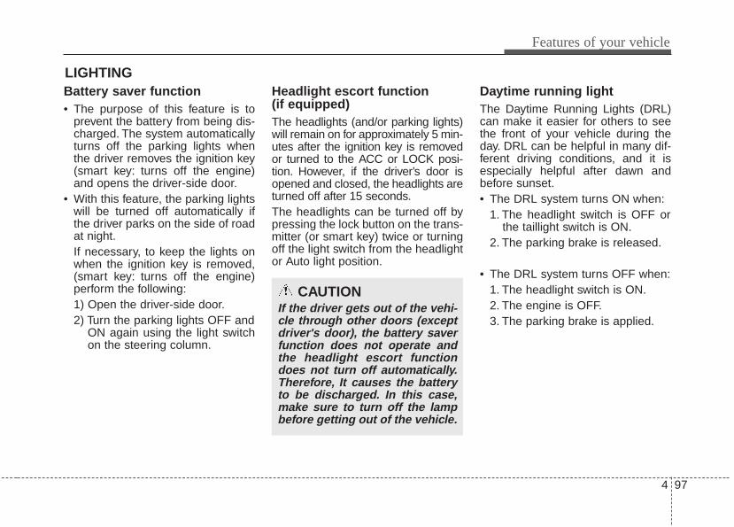
4 97
Features of your vehicle
Battery saver function • The purpose of this feature is to
prevent the battery from being dis-charged. The system automaticallyturns off the parking lights whenthe driver removes the ignition key(smart key: turns off the engine)and opens the driver-side door.
• With this feature, the parking lightswill be turned off automatically ifthe driver parks on the side of roadat night.If necessary, to keep the lights onwhen the ignition key is removed,(smart key: turns off the engine)perform the following:1) Open the driver-side door.2) Turn the parking lights OFF and
ON again using the light switchon the steering column.
Headlight escort function (if equipped)The headlights (and/or parking lights)will remain on for approximately 5 min-utes after the ignition key is removedor turned to the ACC or LOCK posi-tion. However, if the driver’s door isopened and closed, the headlights areturned off after 15 seconds.The headlights can be turned off bypressing the lock button on the trans-mitter (or smart key) twice or turningoff the light switch from the headlightor Auto light position.
Daytime running light The Daytime Running Lights (DRL)can make it easier for others to seethe front of your vehicle during theday. DRL can be helpful in many dif-ferent driving conditions, and it isespecially helpful after dawn andbefore sunset.• The DRL system turns ON when:
1. The headlight switch is OFF orthe taillight switch is ON.
2. The parking brake is released.
• The DRL system turns OFF when:1. The headlight switch is ON.2. The engine is OFF.3. The parking brake is applied.
LIGHTING
CAUTIONIf the driver gets out of the vehi-cle through other doors (exceptdriver's door), the battery saverfunction does not operate andthe headlight escort functiondoes not turn off automatically.Therefore, It causes the batteryto be discharged. In this case,make sure to turn off the lampbefore getting out of the vehicle.
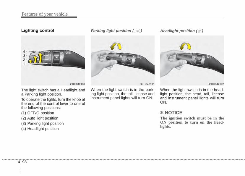
Features of your vehicle
984
Lighting control
The light switch has a Headlight anda Parking light position.To operate the lights, turn the knob atthe end of the control lever to one ofthe following positions:(1) OFF/O position(2) Auto light position(3) Parking light position(4) Headlight position
Parking light position ( )
When the light switch is in the park-ing light position, the tail, license andinstrument panel lights will turn ON.
Headlight position ( )
When the light switch is in the head-light position, the head, tail, licenseand instrument panel lights will turnON.
✽✽ NOTICEThe ignition switch must be in theON position to turn on the head-lights.
OKH042189 OKH042191 OKH042192
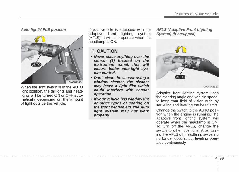
4 99
Features of your vehicle
Auto light/AFLS position
When the light switch is in the AUTOlight position, the taillights and head-lights will be turned ON or OFF auto-matically depending on the amountof light outside the vehicle.
If your vehicle is equipped with theadaptive front lighting system(AFLS), it will also operate when theheadlamp is ON.
AFLS (Adaptive Front LightingSystem) (if equipped)
Adaptive front lighting system usesthe steering angle and vehicle speed,to keep your field of vision wide byswiveling and leveling the headlamp.Change the switch to the AUTO posi-tion when the engine is running. Theadaptive front lighting system willoperate when the headlamp is ON.To turn off the AFLS, change theswitch to other positions. After turn-ing the AFLS off, headlamp swivelingno longer occurs, but leveling oper-ates continuously.
CAUTION• Never place anything over the
sensor (1) located on theinstrument panel, this willensure better auto-light sys-tem control.
• Don’t clean the sensor using awindow cleaner, the cleanermay leave a light film whichcould interfere with sensoroperation.
• If your vehicle has window tintor other types of coating onthe front windshield, the Autolight system may not workproperly.
OKH042187
OVG043181
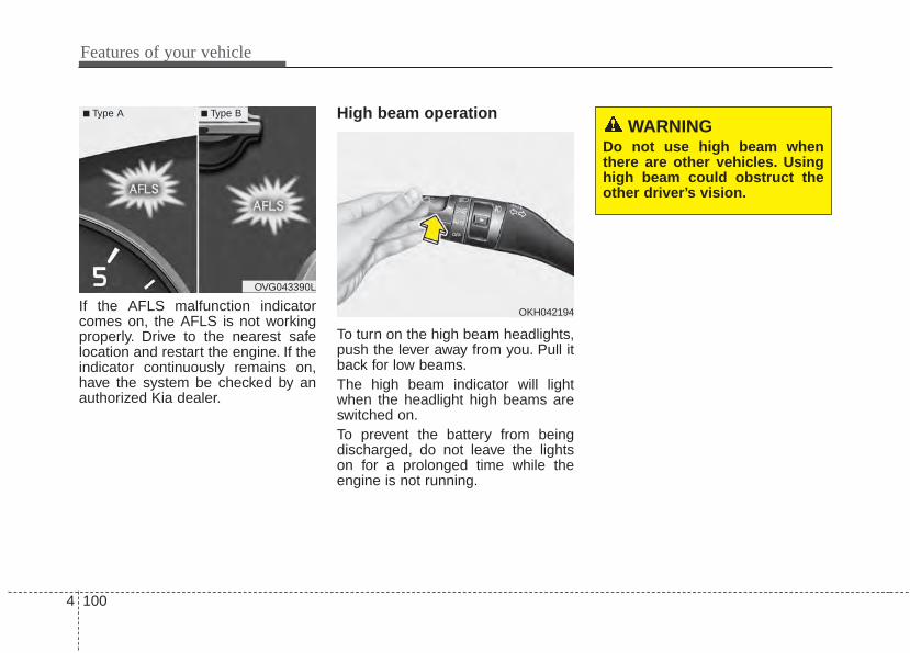
Features of your vehicle
1004
If the AFLS malfunction indicatorcomes on, the AFLS is not workingproperly. Drive to the nearest safelocation and restart the engine. If theindicator continuously remains on,have the system be checked by anauthorized Kia dealer.
High beam operation
To turn on the high beam headlights,push the lever away from you. Pull itback for low beams.The high beam indicator will lightwhen the headlight high beams areswitched on.To prevent the battery from beingdischarged, do not leave the lightson for a prolonged time while theengine is not running.
OVG043390L
■ Type A ■ Type B
WARNINGDo not use high beam whenthere are other vehicles. Usinghigh beam could obstruct theother driver’s vision.
OKH042194
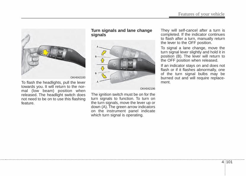
4 101
Features of your vehicle
To flash the headlights, pull the levertowards you. It will return to the nor-mal (low beam) position whenreleased. The headlight switch doesnot need to be on to use this flashingfeature.
Turn signals and lane changesignals
The ignition switch must be on for theturn signals to function. To turn onthe turn signals, move the lever up ordown (A). The green arrow indicatorson the instrument panel indicatewhich turn signal is operating.
They will self-cancel after a turn iscompleted. If the indicator continuesto flash after a turn, manually returnthe lever to the OFF position.To signal a lane change, move theturn signal lever slightly and hold it inposition (B). The lever will return tothe OFF position when released.If an indicator stays on and does notflash or if it flashes abnormally, oneof the turn signal bulbs may beburned out and will require replace-ment.
OKH042193
OKH042196
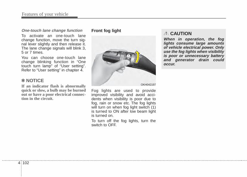
Features of your vehicle
1024
One-touch lane change functionTo activate an one-touch lanechange function, move the turn sig-nal lever slightly and then release it.The lane change signals will blink 3,5 or 7 times.You can choose one-touch lanechange blinking function in “Onetouch turn lamp” of “User setting”.Refer to “User setting” in chapter 4.
✽✽ NOTICEIf an indicator flash is abnormallyquick or slow, a bulb may be burnedout or have a poor electrical connec-tion in the circuit.
Front fog light
Fog lights are used to provideimproved visibility and avoid acci-dents when visibility is poor due tofog, rain or snow etc. The fog lightswill turn on when fog light switch (1)is turned to ON after low beam lightis turned on.To turn off the fog lights, turn theswitch to OFF.
OKH042197
CAUTIONWhen in operation, the foglights consume large amountsof vehicle electrical power. Onlyuse the fog lights when visibilityis poor or unnecessary batteryand generator drain couldoccur.
4 103
Features of your vehicle
Headlight leveling device (if equipped)Automatic typeIt is automatically adjusted the head-light beam level according to thenumber of the passengers and theloading weight in the luggage area.And it offers the proper headlightbeam under the various conditions.
WARNINGIf it is not working properly eventhough your car is inclinedbackward according to passen-ger's posture, or the headlightbeam is irradiated to the high orlow position, have your vehicleinspected by an authorized Kiadealer.Don't attempt to inspect orreplace the wiring yourself toprevent malfunction.
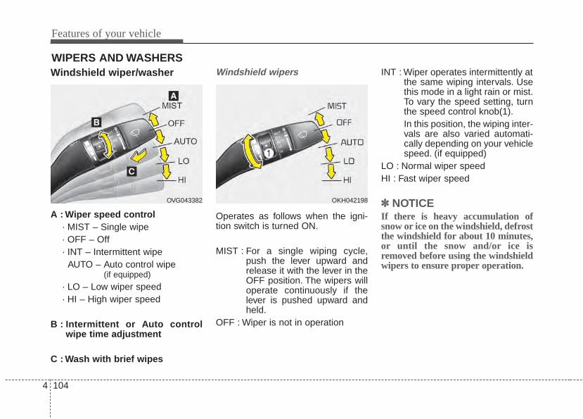
Features of your vehicle
1044
WIPERS AND WASHERSWindshield wiper/washer
A : Wiper speed control· MIST – Single wipe· OFF – Off· INT – Intermittent wipe
AUTO – Auto control wipe (if equipped)
· LO – Low wiper speed· HI – High wiper speed
B : Intermittent or Auto controlwipe time adjustment
C : Wash with brief wipes
Windshield wipers
Operates as follows when the igni-tion switch is turned ON.
MIST : For a single wiping cycle,push the lever upward andrelease it with the lever in theOFF position. The wipers willoperate continuously if thelever is pushed upward andheld.
OFF : Wiper is not in operation
INT : Wiper operates intermittently atthe same wiping intervals. Usethis mode in a light rain or mist.To vary the speed setting, turnthe speed control knob(1).In this position, the wiping inter-vals are also varied automati-cally depending on your vehiclespeed. (if equipped)
LO : Normal wiper speedHI : Fast wiper speed
✽✽ NOTICEIf there is heavy accumulation ofsnow or ice on the windshield, defrostthe windshield for about 10 minutes,or until the snow and/or ice isremoved before using the windshieldwipers to ensure proper operation.
OVG043382 OKH042198
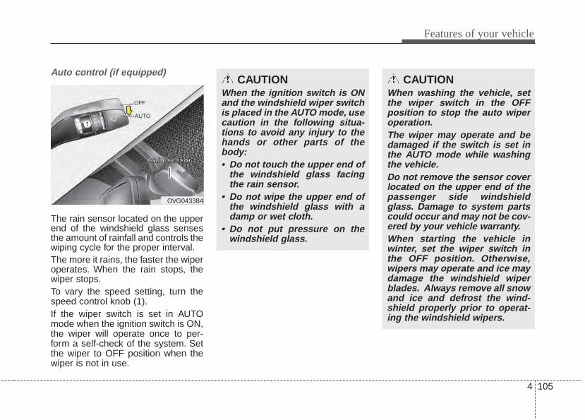
4 105
Features of your vehicle
Auto control (if equipped)
The rain sensor located on the upperend of the windshield glass sensesthe amount of rainfall and controls thewiping cycle for the proper interval.The more it rains, the faster the wiperoperates. When the rain stops, thewiper stops.To vary the speed setting, turn thespeed control knob (1).If the wiper switch is set in AUTOmode when the ignition switch is ON,the wiper will operate once to per-form a self-check of the system. Setthe wiper to OFF position when thewiper is not in use.
CAUTIONWhen the ignition switch is ONand the windshield wiper switchis placed in the AUTO mode, usecaution in the following situa-tions to avoid any injury to thehands or other parts of thebody:• Do not touch the upper end of
the windshield glass facingthe rain sensor.
• Do not wipe the upper end ofthe windshield glass with adamp or wet cloth.
• Do not put pressure on thewindshield glass.
OVG043384
RRRRaaaa iiiinnnn sssseeeennnnssssoooorrrr
CAUTIONWhen washing the vehicle, setthe wiper switch in the OFFposition to stop the auto wiperoperation.The wiper may operate and bedamaged if the switch is set inthe AUTO mode while washingthe vehicle.Do not remove the sensor coverlocated on the upper end of thepassenger side windshieldglass. Damage to system partscould occur and may not be cov-ered by your vehicle warranty.When starting the vehicle inwinter, set the wiper switch inthe OFF position. Otherwise,wipers may operate and ice maydamage the windshield wiperblades. Always remove all snowand ice and defrost the wind-shield properly prior to operat-ing the windshield wipers.
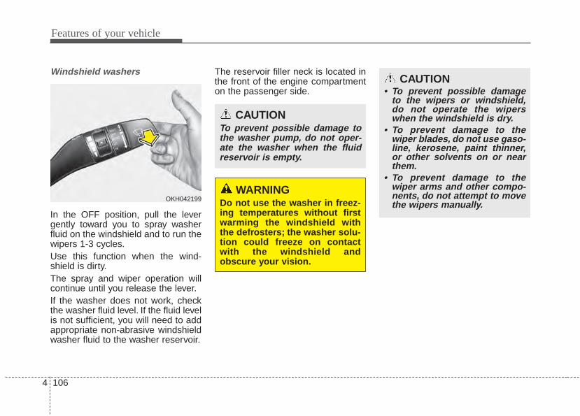
Features of your vehicle
1064
Windshield washers
In the OFF position, pull the levergently toward you to spray washerfluid on the windshield and to run thewipers 1-3 cycles.Use this function when the wind-shield is dirty.The spray and wiper operation willcontinue until you release the lever.If the washer does not work, checkthe washer fluid level. If the fluid levelis not sufficient, you will need to addappropriate non-abrasive windshieldwasher fluid to the washer reservoir.
The reservoir filler neck is located inthe front of the engine compartmenton the passenger side.
OKH042199
CAUTION• To prevent possible damage
to the wipers or windshield,do not operate the wiperswhen the windshield is dry.
• To prevent damage to thewiper blades, do not use gaso-line, kerosene, paint thinner,or other solvents on or nearthem.
• To prevent damage to thewiper arms and other compo-nents, do not attempt to movethe wipers manually.
CAUTIONTo prevent possible damage tothe washer pump, do not oper-ate the washer when the fluidreservoir is empty.
WARNINGDo not use the washer in freez-ing temperatures without firstwarming the windshield withthe defrosters; the washer solu-tion could freeze on contactwith the windshield andobscure your vision.
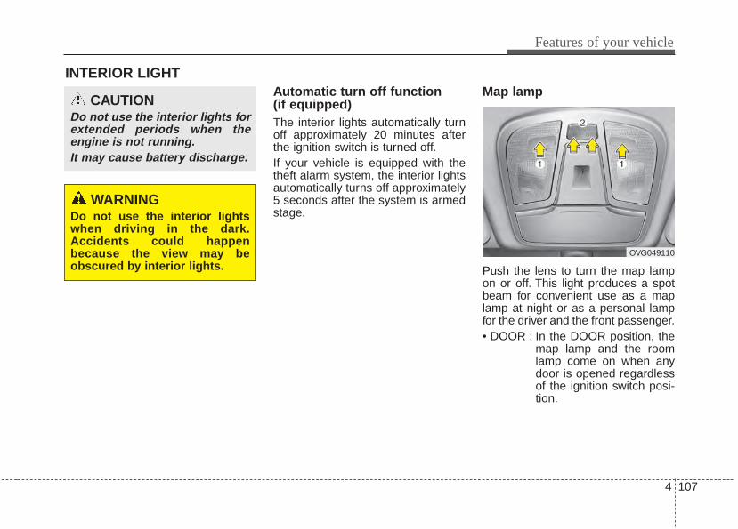
4 107
Features of your vehicle
INTERIOR LIGHTAutomatic turn off function (if equipped)The interior lights automatically turnoff approximately 20 minutes afterthe ignition switch is turned off.If your vehicle is equipped with thetheft alarm system, the interior lightsautomatically turns off approximately5 seconds after the system is armedstage.
Map lamp
Push the lens to turn the map lampon or off. This light produces a spotbeam for convenient use as a maplamp at night or as a personal lampfor the driver and the front passenger.• DOOR : In the DOOR position, the
map lamp and the roomlamp come on when anydoor is opened regardlessof the ignition switch posi-tion.
CAUTIONDo not use the interior lights forextended periods when theengine is not running.It may cause battery discharge.
OVG049110
WARNINGDo not use the interior lightswhen driving in the dark.Accidents could happenbecause the view may beobscured by interior lights.
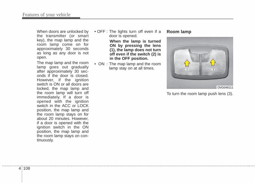
Features of your vehicle
1084
When doors are unlocked bythe transmitter (or smartkey), the map lamp and theroom lamp come on forapproximately 30 secondsas long as any door is notopen.The map lamp and the roomlamp goes out graduallyafter approximately 30 sec-onds if the door is closed.However, if the ignitionswitch is ON or all doors arelocked, the map lamp andthe room lamp will turn offimmediately. If a door isopened with the ignitionswitch in the ACC or LOCKposition, the map lamp andthe room lamp stays on forabout 20 minutes. However,if a door is opened with theignition switch in the ONposition, the map lamp andthe room lamp stays on con-tinuously.
• OFF : The lights turn off even if adoor is opened.When the lamp is turnedON by pressing the lens(1), the lamp does not turnoff even if the switch (2) isin the OFF position.
• ON : The map lamp and the roomlamp stay on at all times.
Room lamp
To turn the room lamp push lens (3).
OVG049111
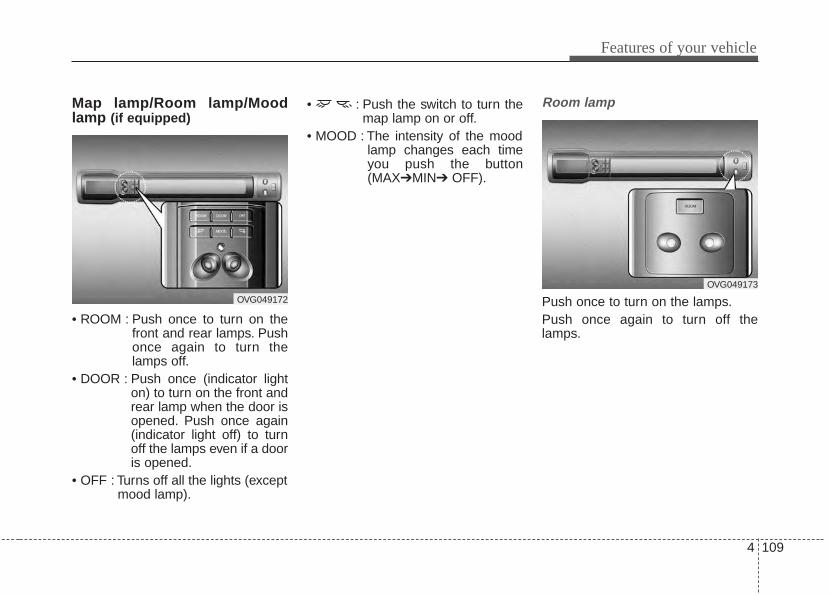
4 109
Features of your vehicle
Map lamp/Room lamp/Moodlamp (if equipped)
• ROOM : Push once to turn on thefront and rear lamps. Pushonce again to turn thelamps off.
• DOOR : Push once (indicator lighton) to turn on the front andrear lamp when the door isopened. Push once again(indicator light off) to turnoff the lamps even if a dooris opened.
• OFF : Turns off all the lights (exceptmood lamp).
• : Push the switch to turn themap lamp on or off.
• MOOD : The intensity of the moodlamp changes each timeyou push the button(MAX➔MIN➔ OFF).
Room lamp
Push once to turn on the lamps.Push once again to turn off thelamps.
OVG049172
OVG049173
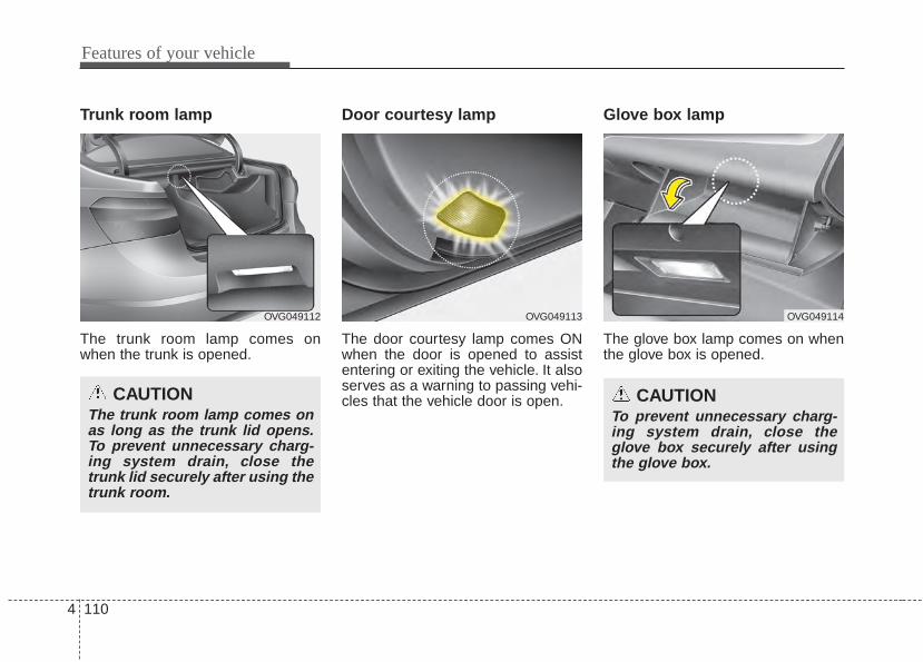
Features of your vehicle
1104
Trunk room lamp
The trunk room lamp comes onwhen the trunk is opened.
Door courtesy lamp
The door courtesy lamp comes ONwhen the door is opened to assistentering or exiting the vehicle. It alsoserves as a warning to passing vehi-cles that the vehicle door is open.
Glove box lamp
The glove box lamp comes on whenthe glove box is opened.
OVG049112
CAUTIONThe trunk room lamp comes onas long as the trunk lid opens.To prevent unnecessary charg-ing system drain, close thetrunk lid securely after using thetrunk room.
OVG049114
CAUTIONTo prevent unnecessary charg-ing system drain, close theglove box securely after usingthe glove box.
OVG049113
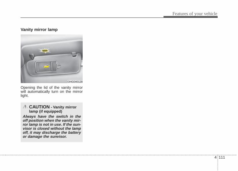
4 111
Features of your vehicle
Vanity mirror lamp
Opening the lid of the vanity mirrorwill automatically turn on the mirrorlight.
OHG040128
CAUTION - Vanity mirrorlamp (if equipped)
Always have the switch in theoff position when the vanity mir-ror lamp is not in use. If the sun-visor is closed without the lampoff, it may discharge the batteryor damage the sunvisor.
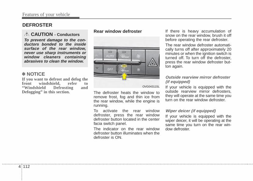
Features of your vehicle
1124
DEFROSTER
✽✽ NOTICEIf you want to defrost and defog thefront windshield, refer to“Windshield Defrosting andDefogging” in this section.
Rear window defroster
The defroster heats the window toremove frost, fog and thin ice fromthe rear window, while the engine isrunning.To activate the rear windowdefroster, press the rear windowdefroster button located in the centerfacia switch panel.The indicator on the rear windowdefroster button illuminates when thedefroster is ON.
If there is heavy accumulation ofsnow on the rear window, brush it offbefore operating the rear defroster.The rear window defroster automati-cally turns off after approximately 20minutes or when the ignition switch isturned off. To turn off the defroster,press the rear window defroster but-ton again.
Outside rearview mirror defroster (if equipped)If your vehicle is equipped with theoutside rearview mirror defrosters,they will operate at the same time youturn on the rear window defroster.
Wiper deicer (if equipped)If your vehicle is equipped with thewiper deicer, it will be operating at thesame time you turn on the rear win-dow defroster.
CAUTION - ConductorsTo prevent damage to the con-ductors bonded to the insidesurface of the rear window,never use sharp instruments orwindow cleaners containingabrasives to clean the window.
OVG043115L

4 113
Features of your vehicle
AUTOMATIC CLIMATE CONTROL SYSTEM
OVG043121N
1. Driver’s temperature control button
2. AUTO (automatic control) button
3. Front windshield defroster button
4. Fan speed control button
5. OFF button
6. Rear window defroster button
7. Mode selection button
8. Air intake control button
9. Dual temperature control selection button
10. Passenger's temperature control button
11. Air conditioning button
12. Climate information screen selection button
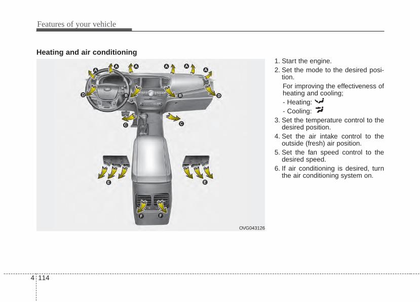
Features of your vehicle
1144
OVG043126
Heating and air conditioning1. Start the engine.2. Set the mode to the desired posi-
tion.For improving the effectiveness ofheating and cooling;- Heating:- Cooling:
3. Set the temperature control to thedesired position.
4. Set the air intake control to theoutside (fresh) air position.
5. Set the fan speed control to thedesired speed.
6. If air conditioning is desired, turnthe air conditioning system on.
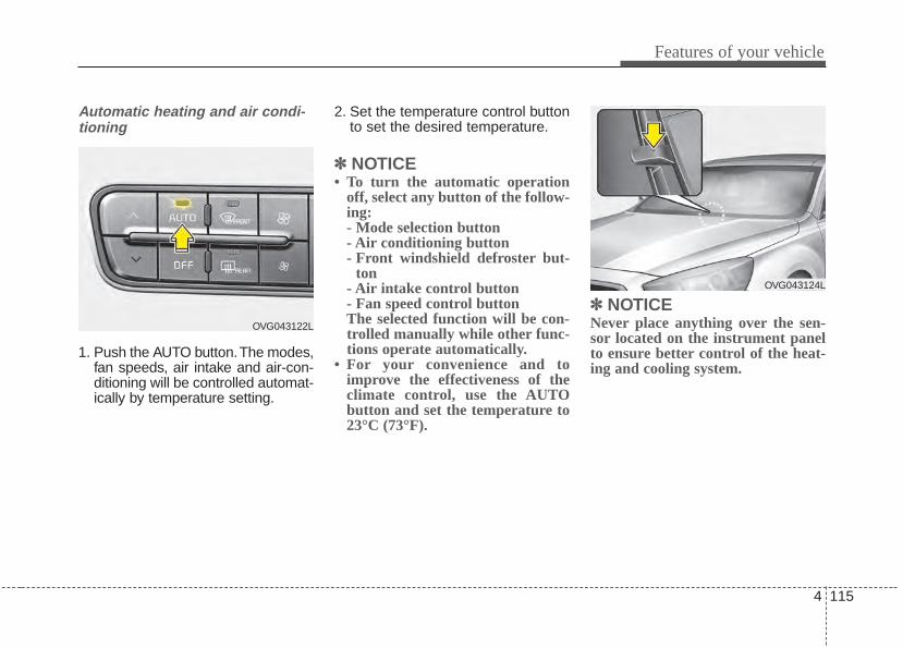
4 115
Features of your vehicle
Automatic heating and air condi-tioning
1. Push the AUTO button.The modes,fan speeds, air intake and air-con-ditioning will be controlled automat-ically by temperature setting.
2. Set the temperature control buttonto set the desired temperature.
✽✽ NOTICE• To turn the automatic operation
off, select any button of the follow-ing:- Mode selection button- Air conditioning button- Front windshield defroster but-
ton- Air intake control button- Fan speed control buttonThe selected function will be con-trolled manually while other func-tions operate automatically.
• For your convenience and toimprove the effectiveness of theclimate control, use the AUTObutton and set the temperature to23°C (73°F).
✽✽ NOTICENever place anything over the sen-sor located on the instrument panelto ensure better control of the heat-ing and cooling system.
OVG043124L
OVG043122L
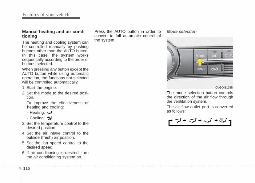
Features of your vehicle
1164
Manual heating and air condi-tioningThe heating and cooling system canbe controlled manually by pushingbuttons other than the AUTO button.In this case, the system workssequentially according to the order ofbuttons selected.When pressing any button except theAUTO button while using automaticoperation, the functions not selectedwill be controlled automatically.1. Start the engine.2. Set the mode to the desired posi-
tion.To improve the effectiveness ofheating and cooling:- Heating:- Cooling:
3. Set the temperature control to thedesired position.
4. Set the air intake control to theoutside (fresh) air position.
5. Set the fan speed control to thedesired speed.
6. If air conditioning is desired, turnthe air conditioning system on.
Press the AUTO button in order toconvert to full automatic control ofthe system.
Mode selection
The mode selection button controlsthe direction of the air flow throughthe ventilation system.The air flow outlet port is convertedas follows:
OVG043125N
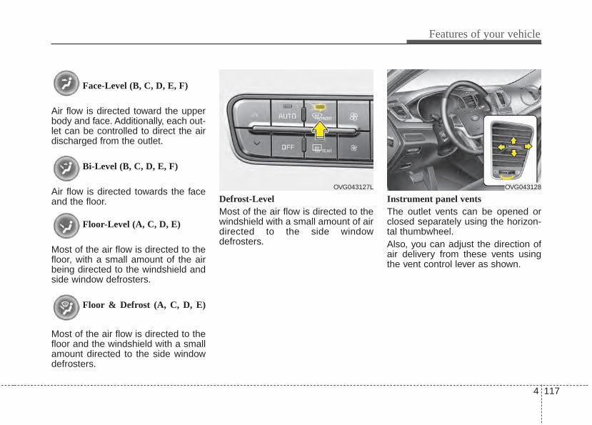
4 117
Features of your vehicle
Face-Level (B, C, D, E, F)
Air flow is directed toward the upperbody and face. Additionally, each out-let can be controlled to direct the airdischarged from the outlet.
Bi-Level (B, C, D, E, F)
Air flow is directed towards the faceand the floor.
Floor-Level (A, C, D, E)
Most of the air flow is directed to thefloor, with a small amount of the airbeing directed to the windshield andside window defrosters.
Floor & Defrost (A, C, D, E)
Most of the air flow is directed to thefloor and the windshield with a smallamount directed to the side windowdefrosters.
Defrost-LevelMost of the air flow is directed to thewindshield with a small amount of airdirected to the side windowdefrosters.
Instrument panel ventsThe outlet vents can be opened orclosed separately using the horizon-tal thumbwheel.Also, you can adjust the direction ofair delivery from these vents usingthe vent control lever as shown.
OVG043127L OVG043128

Features of your vehicle
1184
Temperature control
The temperature will increase to themaximum by pushing the up ( )button.The temperature will decrease to theminimum by pushing the down ( )button.When pushing the button, the tem-perature will increase or decrease by0.5°C / 1°F. When set to the lowesttemperature setting, the air condi-tioning will operate continuously.
Adjusting the driver and passengerside temperature individually 1. Press the DUAL button to operate
the driver and passenger sidetemperature individually. Pressingthe right temperature control but-ton will automatically switch to theDUAL mode as well.
2. Operate the left temperature con-trol to adjust the driver side tem-perature. Operate the right tem-perature control to adjust the pas-senger side temperature.
Adjusting the driver and passengerside temperature equally1. Press the DUAL button again to
deactivate DUAL mode. The pas-senger side temperature will beset to the same temperature asthe driver side temperature.
2. Operate the driver side tempera-ture control button. The driver andpassenger side temperature willbe adjusted equally.
Temperature conversionYou can switch the temperaturemode from Centigrade to Fahrenheitas follows:While pressing the OFF button,press the AUTO button for 3 secondsor more.The display will change fromCentigrade to Fahrenheit, or fromFahrenheit to Centigrade.If the battery has been discharged ordisconnected, the temperature modedisplay will reset to Fahrenheit.
OVG043129
■ Driver’s side ■ Passenger’s side
OVG043130
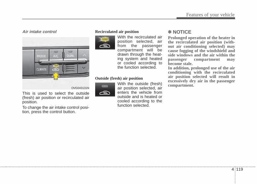
4 119
Features of your vehicle
Air intake control
This is used to select the outside(fresh) air position or recirculated airposition.To change the air intake control posi-tion, press the control button.
Recirculated air positionWith the recirculated airposition selected, airfrom the passengercompartment will bedrawn through the heat-ing system and heatedor cooled according tothe function selected.
Outside (fresh) air positionWith the outside (fresh)air position selected, airenters the vehicle fromoutside and is heated orcooled according to thefunction selected.
✽✽ NOTICEProlonged operation of the heater inthe recirculated air position (with-out air conditioning selected) maycause fogging of the windshield andside windows and the air within thepassenger compartment maybecome stale.In addition, prolonged use of the airconditioning with the recirculatedair position selected will result inexcessively dry air in the passengercompartment.
OVG043131N
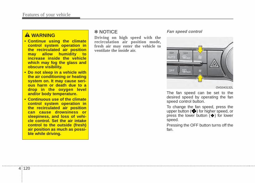
Features of your vehicle
1204
✽✽ NOTICEDriving on high speed with therecirculation air position mode,fresh air may enter the vehicle toventilate the inside air.
Fan speed control
The fan speed can be set to thedesired speed by operating the fanspeed control button.To change the fan speed, press theupper button ( ) for higher speed, orpress the lower button ( ) for lowerspeed.Pressing the OFF button turns off thefan.
WARNING• Continue using the climate
control system operation inthe recirculated air positionmay allow humidity toincrease inside the vehiclewhich may fog the glass andobscure visibility.
• Do not sleep in a vehicle withthe air conditioning or heatingsystem on. It may cause seri-ous harm or death due to adrop in the oxygen leveland/or body temperature.
• Continuous use of the climatecontrol system operation inthe recirculated air positioncan cause drowsiness orsleepiness, and loss of vehi-cle control. Set the air intakecontrol to the outside (fresh)air position as much as possi-ble while driving.
OVG043132L
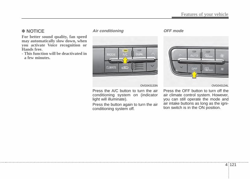
4 121
Features of your vehicle
✽✽ NOTICEFor better sound quality, fan speedmay automatically slow down, whenyou activate Voice recognition orHands free.- This function will be deactivated in
a few minutes.
Air conditioning
Press the A/C button to turn the airconditioning system on (indicatorlight will illuminate).Press the button again to turn the airconditioning system off.
OFF mode
Press the OFF button to turn off theair climate control system. However,you can still operate the mode andair intake buttons as long as the igni-tion switch is in the ON position.
OVG043134LOVG043133N
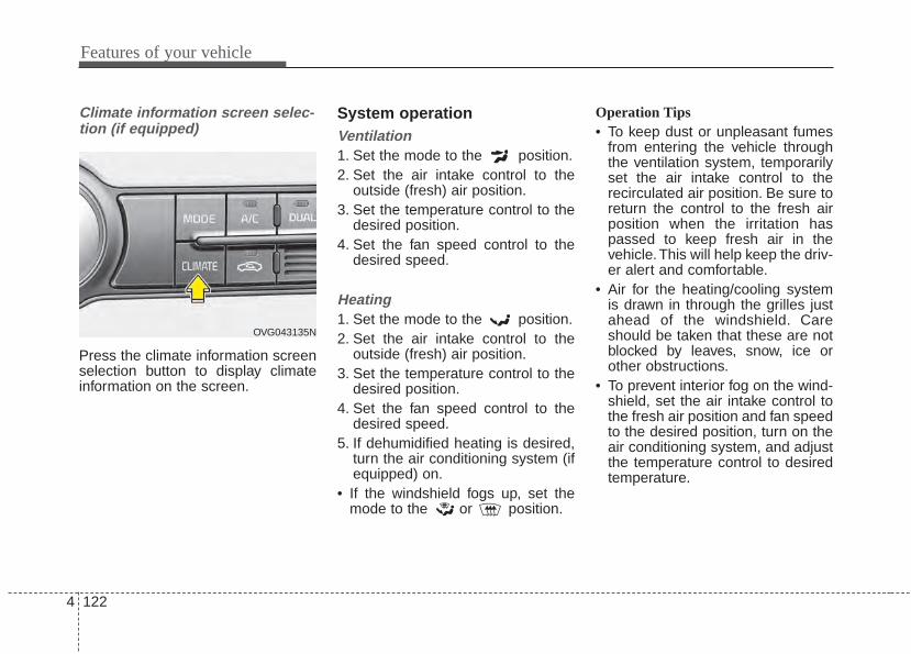
Features of your vehicle
1224
Climate information screen selec-tion (if equipped)
Press the climate information screenselection button to display climateinformation on the screen.
System operationVentilation1. Set the mode to the position.2. Set the air intake control to the
outside (fresh) air position.3. Set the temperature control to the
desired position.4. Set the fan speed control to the
desired speed.
Heating1. Set the mode to the position.2. Set the air intake control to the
outside (fresh) air position.3. Set the temperature control to the
desired position.4. Set the fan speed control to the
desired speed.5. If dehumidified heating is desired,
turn the air conditioning system (ifequipped) on.
• If the windshield fogs up, set themode to the or position.
Operation Tips• To keep dust or unpleasant fumes
from entering the vehicle throughthe ventilation system, temporarilyset the air intake control to therecirculated air position. Be sure toreturn the control to the fresh airposition when the irritation haspassed to keep fresh air in thevehicle. This will help keep the driv-er alert and comfortable.
• Air for the heating/cooling systemis drawn in through the grilles justahead of the windshield. Careshould be taken that these are notblocked by leaves, snow, ice orother obstructions.
• To prevent interior fog on the wind-shield, set the air intake control tothe fresh air position and fan speedto the desired position, turn on theair conditioning system, and adjustthe temperature control to desiredtemperature.
OVG043135N
4 123
Features of your vehicle
Air conditioningKia Air Conditioning Systems arefilled with environmentally friendly R-134a refrigerant.1. Start the engine. Press the air con-
ditioning button.2. Set the mode to the position.3. Set the air intake control to the
outside air or recirculated air posi-tion.
4. Adjust the fan speed control andtemperature control to maintainmaximum comfort.
✽✽ NOTICE• When using the air conditioning
system, monitor the temperaturegauge closely while driving uphills or in heavy traffic when out-side temperatures are high. Airconditioning system operationmay cause engine overheating.Continue to use the blower fan butturn the air conditioning systemoff if the temperature gauge indi-cates engine overheating.
• When opening the windows inhumid weather air conditioningmay create water droplets insidethe vehicle. Since excessive waterdroplets may cause damage toelectrical equipment, air condi-tioning should only be used withthe windows closed.
Air conditioning system operation tips • If the vehicle has been parked in
direct sunlight during hot weather,open the windows for a short timeto let the hot air inside the vehicleescape.
• To help reduce moisture inside ofthe windows on rainy or humiddays, decrease the humidity insidethe vehicle by operating the airconditioning system.
• During air conditioning systemoperation, you may occasionallynotice a slight change in enginespeed as the air conditioning com-pressor cycles. This is a normalsystem operation characteristic.
• Use the air conditioning systemevery month only for a few minutesto ensure maximum system per-formance.
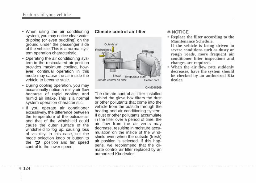
Features of your vehicle
1244
• When using the air conditioningsystem, you may notice clear waterdripping (or even puddling) on theground under the passenger sideof the vehicle. This is a normal sys-tem operation characteristic.
• Operating the air conditioning sys-tem in the recirculated air positionprovides maximum cooling, how-ever, continual operation in thismode may cause the air inside thevehicle to become stale.
• During cooling operation, you mayoccasionally notice a misty air flowbecause of rapid cooling andhumid air intake. This is a normalsystem operation characteristic.
• If you operate air conditionerexcessively, the difference betweenthe temperature of the outside airand that of the windshield couldcause the outer surface of thewindshield to fog up, causing lossof visibility. In this case, set themode selection knob or button tothe position and fan speedcontrol to the lower speed.
Climate control air filter
The climate control air filter installedbehind the glove box filters the dustor other pollutants that come into thevehicle from the outside through theheating and air conditioning system.If dust or other pollutants accumulatein the filter over a period of time, theair flow from the air vents maydecrease, resulting in moisture accu-mulation on the inside of the wind-shield even when the outside (fresh)air position is selected. If this hap-pens, we recommend that the cli-mate control air filter replaced by anauthorized Kia dealer.
✽✽ NOTICE• Replace the filter according to the
Maintenance Schedule.If the vehicle is being driven insevere conditions such as dusty orrough roads, more frequent airconditioner filter inspections andchanges are required.
• When the air flow rate suddenlydecreases, have the system shouldbe checked by an authorized Kiadealer.
OHM048209
Outside air
Recirculatedair
Climate control air filter
Blower Evaporator coreHeater core
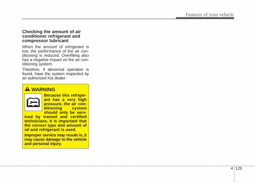
4 125
Features of your vehicle
Checking the amount of airconditioner refrigerant andcompressor lubricantWhen the amount of refrigerant islow, the performance of the air con-ditioning is reduced. Overfilling alsohas a negative impact on the air con-ditioning system.Therefore, if abnormal operation isfound, have the system inspected byan authorized Kia dealer.
WARNINGBecause this refriger-ant has a very highpressure, the air con-ditioning systemshould only be serv-
iced by trained and certifiedtechnicians. It is important thatthe correct type and amount ofoil and refrigerant is used.Improper service may resule in, itmay cause damage to the vehicleand personal injury.
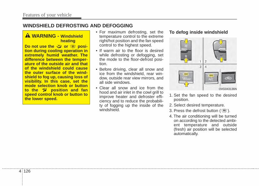
Features of your vehicle
1264
WINDSHIELD DEFROSTING AND DEFOGGING• For maximum defrosting, set the
temperature control to the extremeright/hot position and the fan speedcontrol to the highest speed.
• If warm air to the floor is desiredwhile defrosting or defogging, setthe mode to the floor-defrost posi-tion.
• Before driving, clear all snow andice from the windshield, rear win-dow, outside rear view mirrors, andall side windows.
• Clear all snow and ice from thehood and air inlet in the cowl grill toimprove heater and defroster effi-ciency and to reduce the probabili-ty of fogging up the inside of thewindshield.
To defog inside windshield
1. Set the fan speed to the desiredposition.
2. Select desired temperature.3. Press the defrost button ( ).4. The air conditioning will be turned
on according to the detected ambi-ent temperature and outside(fresh) air position will be selectedautomatically.
WARNING - Windshieldheating
Do not use the or posi-tion during cooling operation inextremely humid weather. Thedifference between the temper-ature of the outside air and thatof the windshield could causethe outer surface of the wind-shield to fog up, causing loss ofvisibility. In this case, set themode selection knob or buttonto the position and fanspeed control knob or button tothe lower speed.
OVG043136N
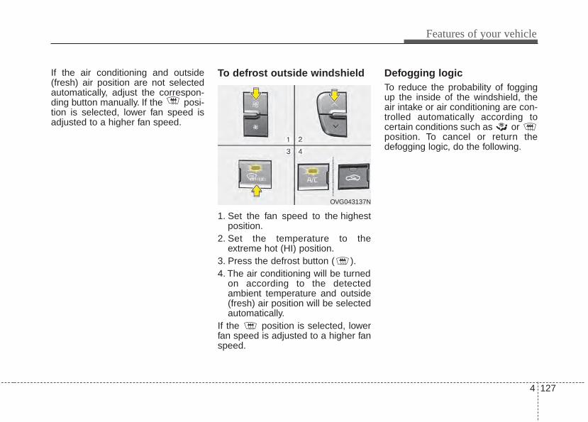
4 127
Features of your vehicle
If the air conditioning and outside(fresh) air position are not selectedautomatically, adjust the correspon-ding button manually. If the posi-tion is selected, lower fan speed isadjusted to a higher fan speed.
To defrost outside windshield
1. Set the fan speed to the highestposition.
2. Set the temperature to theextreme hot (HI) position.
3. Press the defrost button ( ).4. The air conditioning will be turned
on according to the detectedambient temperature and outside(fresh) air position will be selectedautomatically.
If the position is selected, lowerfan speed is adjusted to a higher fanspeed.
Defogging logicTo reduce the probability of foggingup the inside of the windshield, theair intake or air conditioning are con-trolled automatically according tocertain conditions such as or position. To cancel or return thedefogging logic, do the following.
OVG043137N
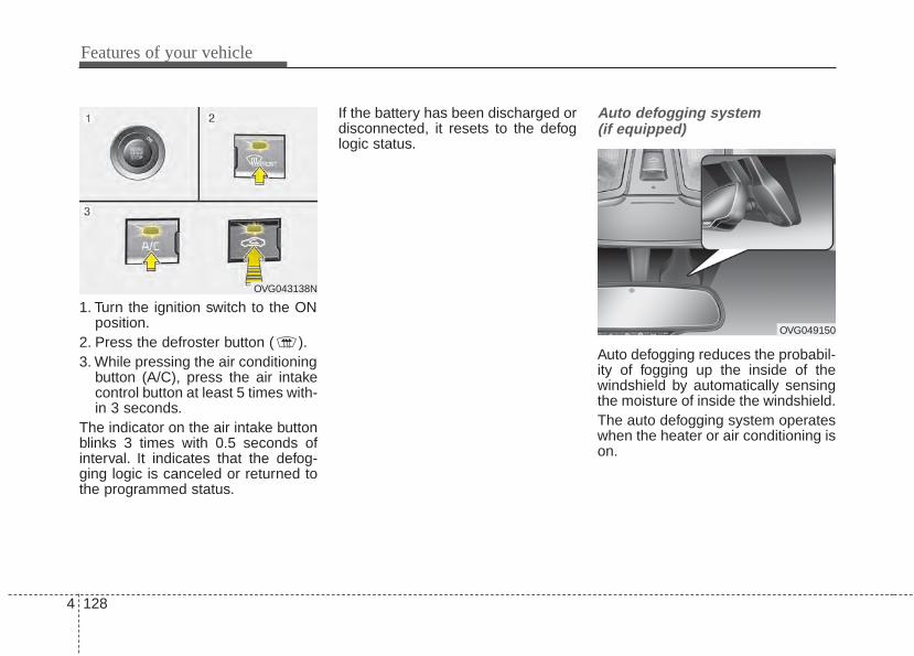
Features of your vehicle
1284
1. Turn the ignition switch to the ONposition.
2. Press the defroster button ( ).3. While pressing the air conditioning
button (A/C), press the air intakecontrol button at least 5 times with-in 3 seconds.
The indicator on the air intake buttonblinks 3 times with 0.5 seconds ofinterval. It indicates that the defog-ging logic is canceled or returned tothe programmed status.
If the battery has been discharged ordisconnected, it resets to the defoglogic status.
Auto defogging system (if equipped)
Auto defogging reduces the probabil-ity of fogging up the inside of thewindshield by automatically sensingthe moisture of inside the windshield.The auto defogging system operateswhen the heater or air conditioning ison.
OVG043138N
OVG049150
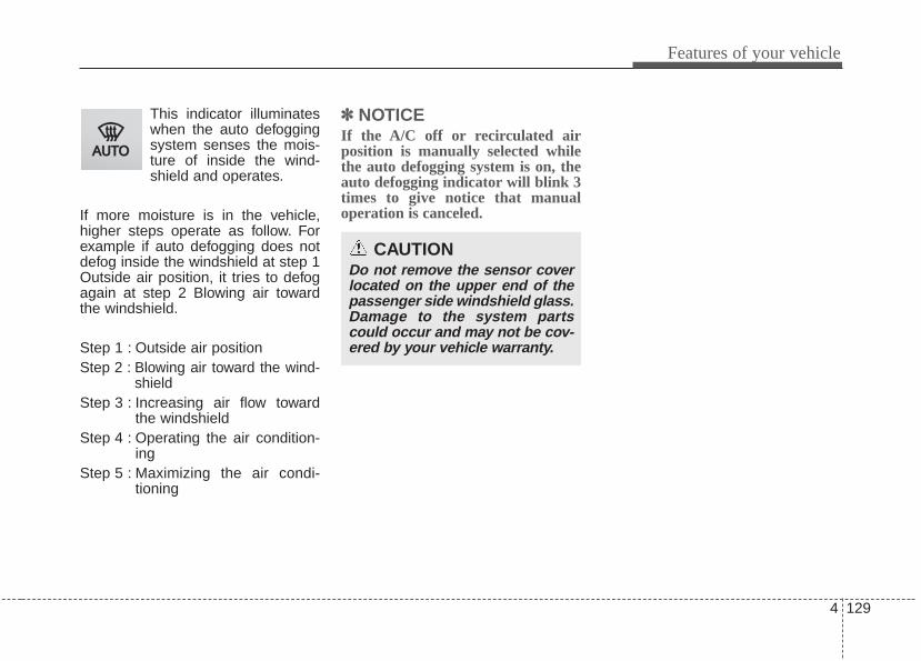
4 129
Features of your vehicle
This indicator illuminateswhen the auto defoggingsystem senses the mois-ture of inside the wind-shield and operates.
If more moisture is in the vehicle,higher steps operate as follow. Forexample if auto defogging does notdefog inside the windshield at step 1Outside air position, it tries to defogagain at step 2 Blowing air towardthe windshield.
Step 1 : Outside air positionStep 2 : Blowing air toward the wind-
shieldStep 3 : Increasing air flow toward
the windshieldStep 4 : Operating the air condition-
ing Step 5 : Maximizing the air condi-
tioning
✽✽ NOTICEIf the A/C off or recirculated airposition is manually selected whilethe auto defogging system is on, theauto defogging indicator will blink 3times to give notice that manualoperation is canceled.
CAUTIONDo not remove the sensor coverlocated on the upper end of thepassenger side windshield glass.Damage to the system partscould occur and may not be cov-ered by your vehicle warranty.
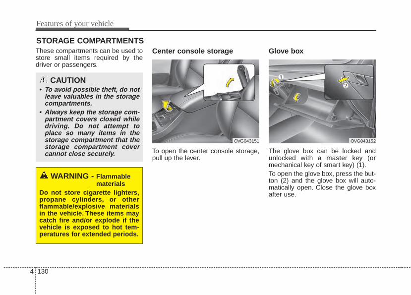
Features of your vehicle
1304
STORAGE COMPARTMENTSThese compartments can be used tostore small items required by thedriver or passengers.
Center console storage
To open the center console storage,pull up the lever.
Glove box
The glove box can be locked andunlocked with a master key (ormechanical key of smart key) (1).To open the glove box, press the but-ton (2) and the glove box will auto-matically open. Close the glove boxafter use.
WARNING - Flammablematerials
Do not store cigarette lighters,propane cylinders, or otherflammable/explosive materialsin the vehicle. These items maycatch fire and/or explode if thevehicle is exposed to hot tem-peratures for extended periods.
CAUTION• To avoid possible theft, do not
leave valuables in the storagecompartments.
• Always keep the storage com-partment covers closed whiledriving. Do not attempt toplace so many items in thestorage compartment that thestorage compartment covercannot close securely.
OVG043152OVG043151
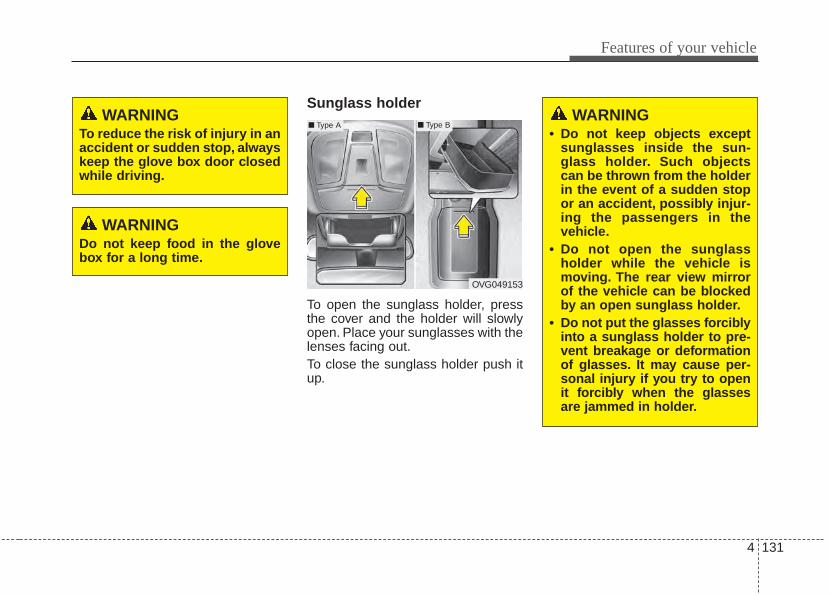
4 131
Features of your vehicle
Sunglass holder
To open the sunglass holder, pressthe cover and the holder will slowlyopen. Place your sunglasses with thelenses facing out.To close the sunglass holder push itup.
WARNING To reduce the risk of injury in anaccident or sudden stop, alwayskeep the glove box door closedwhile driving.
WARNING Do not keep food in the glovebox for a long time.
OVG049153
WARNING• Do not keep objects except
sunglasses inside the sun-glass holder. Such objectscan be thrown from the holderin the event of a sudden stopor an accident, possibly injur-ing the passengers in thevehicle.
• Do not open the sunglassholder while the vehicle ismoving. The rear view mirrorof the vehicle can be blockedby an open sunglass holder.
• Do not put the glasses forciblyinto a sunglass holder to pre-vent breakage or deformationof glasses. It may cause per-sonal injury if you try to openit forcibly when the glassesare jammed in holder.
■ Type A ■ Type B
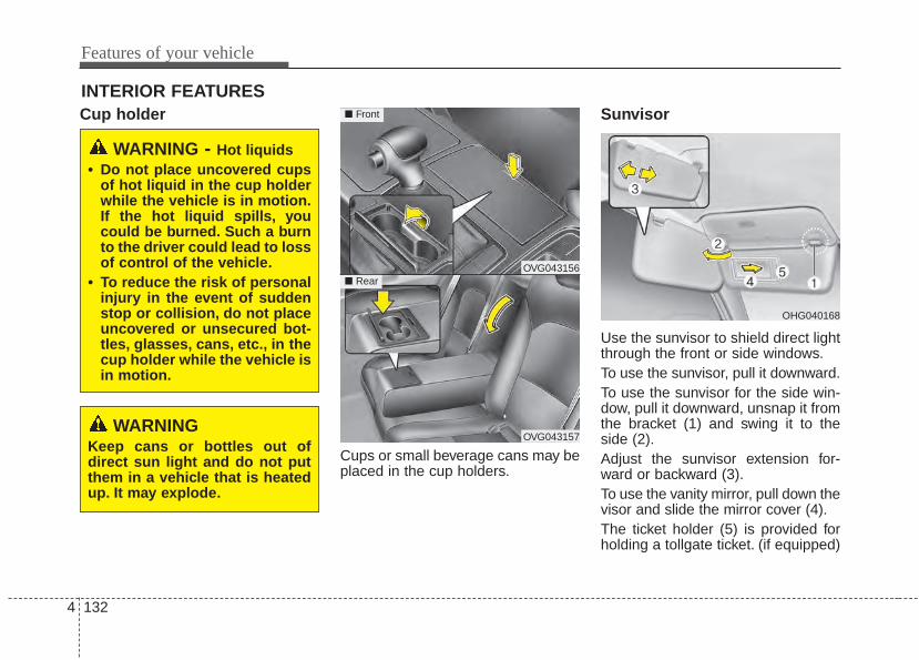
Features of your vehicle
1324
INTERIOR FEATURESCup holder
Cups or small beverage cans may beplaced in the cup holders.
Sunvisor
Use the sunvisor to shield direct lightthrough the front or side windows.To use the sunvisor, pull it downward.To use the sunvisor for the side win-dow, pull it downward, unsnap it fromthe bracket (1) and swing it to theside (2).Adjust the sunvisor extension for-ward or backward (3).To use the vanity mirror, pull down thevisor and slide the mirror cover (4).The ticket holder (5) is provided forholding a tollgate ticket. (if equipped)
WARNING - Hot liquids• Do not place uncovered cups
of hot liquid in the cup holderwhile the vehicle is in motion.If the hot liquid spills, youcould be burned. Such a burnto the driver could lead to lossof control of the vehicle.
• To reduce the risk of personalinjury in the event of suddenstop or collision, do not placeuncovered or unsecured bot-tles, glasses, cans, etc., in thecup holder while the vehicle isin motion.
OHG040168
WARNINGKeep cans or bottles out ofdirect sun light and do not putthem in a vehicle that is heatedup. It may explode.
OVG043156
OVG043157
■ Front
■ Rear
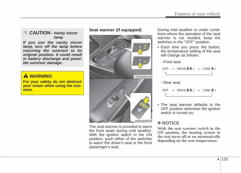
4 133
Features of your vehicle
Seat warmer (if equipped)
The seat warmer is provided to warmthe front seats during cold weather.With the ignition switch in the ONposition, push either of the switchesto warm the driver's seat or the frontpassenger's seat.
During mild weather or under condi-tions where the operation of the seatwarmer is not needed, keep theswitches in the "OFF" position.• Each time you press the button,
the temperature setting of the seatwill change as follows :
- Front seat
- Rear seat
• The seat warmer defaults to theOFF position whenever the ignitionswitch is turned on.
✽✽ NOTICEWith the seat warmer switch in theON position, the heating system inthe seat turns off or on automaticallydepending on the seat temperature.
CAUTION - Vanity mirrorlamp
If you use the vanity mirrorlamp, turn off the lamp beforereturning the sunvisor to itsoriginal position. It could resultin battery discharge and possi-ble sunvisor damage.
WARNINGFor your safety, do not obstructyour vision when using the sun-visor.
OFF → HIGH( ) → LOW( )
→
OFF → HIGH( ) → LOW( )
→
OVG033013N
OVG033307N
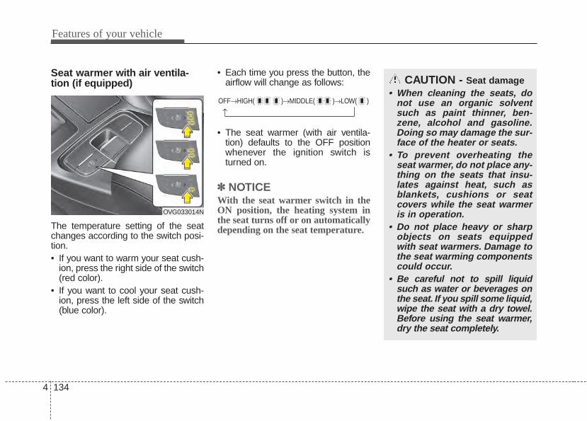
Features of your vehicle
1344
Seat warmer with air ventila-tion (if equipped)
The temperature setting of the seatchanges according to the switch posi-tion.• If you want to warm your seat cush-
ion, press the right side of the switch(red color).
• If you want to cool your seat cush-ion, press the left side of the switch(blue color).
• Each time you press the button, theairflow will change as follows:
• The seat warmer (with air ventila-tion) defaults to the OFF positionwhenever the ignition switch isturned on.
✽✽ NOTICEWith the seat warmer switch in theON position, the heating system inthe seat turns off or on automaticallydepending on the seat temperature.
OFF→HIGH( )→MIDDLE( )→LOW( )
→
CAUTION - Seat damage• When cleaning the seats, do
not use an organic solventsuch as paint thinner, ben-zene, alcohol and gasoline.Doing so may damage the sur-face of the heater or seats.
• To prevent overheating theseat warmer, do not place any-thing on the seats that insu-lates against heat, such asblankets, cushions or seatcovers while the seat warmeris in operation.
• Do not place heavy or sharpobjects on seats equippedwith seat warmers. Damage tothe seat warming componentscould occur.
• Be careful not to spill liquidsuch as water or beverages onthe seat. If you spill some liquid,wipe the seat with a dry towel.Before using the seat warmer,dry the seat completely.
OVG033014N
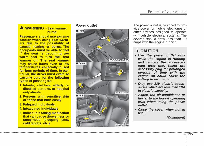
4 135
Features of your vehicle
Power outlet The power outlet is designed to pro-vide power for mobile telephones orother devices designed to operatewith vehicle electrical systems. Thedevices should draw less than 10amps with the engine running.
OVG043402NPSD
OVG043158
OVG043190
■ Center
■ Front
■ Rear
CAUTION• Use the power outlet only
when the engine is runningand remove the accessoryplug after use. Using theaccessory plug for prolongedperiods of time with theengine off could cause thebattery to discharge.
• Only use 12V electric acces-sories which are less than 10Ain electric capacity.
• Adjust the air-conditioner orheater to the lowest operatinglevel when using the poweroutlet.
• Close the cover when not inuse.
(Continued)
WARNING - Seat warmerburns
Passengers should use extremecaution when using seat warm-ers due to the possibility ofexcess heating or burns. Theoccupants must be able to feelif the seat is becoming toowarm and to turn the seatwarmer off. The seat warmermay cause burns even at lowtemperatures, especially if usedfor long periods of time. In par-ticular, the driver must exerciseextreme care for the followingtypes of passengers:1. Infants, children, elderly or
disabled persons, or hospitaloutpatients
2. Persons with sensitive skinor those that burn easily
3. Fatigued individuals4. Intoxicated individuals5. Individuals taking medication
that can cause drowsiness orsleepiness (sleeping pills,cold tablets, etc.)
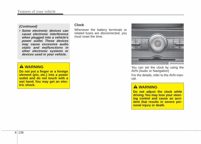
Features of your vehicle
1364
ClockWhenever the battery terminals orrelated fuses are disconnected, youmust reset the time.
You can set the clock by using theAVN (Audio or Navigation)For the details, refer to the AVN man-ual.
OVG043161N
WARNINGDo not adjust the clock whiledriving.You may lose your steer-ing control and cause an acci-dent that results in severe per-sonal injury or death.
WARNINGDo not put a finger or a foreignelement (pin, etc.) into a poweroutlet and do not touch with awet hand. You may get an elec-tric shock.
(Continued)• Some electronic devices can
cause electronic interferencewhen plugged into a vehicle’spower outlet. These devicesmay cause excessive audiostatic and malfunctions inother electronic systems ordevices used in your vehicle.
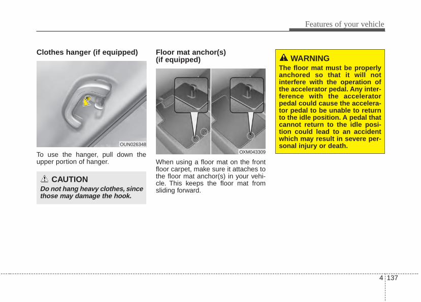
4 137
Features of your vehicle
Clothes hanger (if equipped)
To use the hanger, pull down theupper portion of hanger.
Floor mat anchor(s) (if equipped)
When using a floor mat on the frontfloor carpet, make sure it attaches tothe floor mat anchor(s) in your vehi-cle. This keeps the floor mat fromsliding forward.
CAUTIONDo not hang heavy clothes, sincethose may damage the hook.
OUN026348
OXM043309
WARNINGThe floor mat must be properlyanchored so that it will notinterfere with the operation ofthe accelerator pedal. Any inter-ference with the acceleratorpedal could cause the accelera-tor pedal to be unable to returnto the idle position. A pedal thatcannot return to the idle posi-tion could lead to an accidentwhich may result in severe per-sonal injury or death.
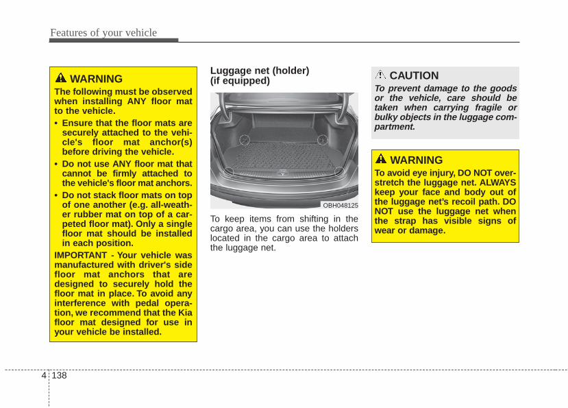
Features of your vehicle
1384
Luggage net (holder) (if equipped)
To keep items from shifting in thecargo area, you can use the holderslocated in the cargo area to attachthe luggage net.
CAUTIONTo prevent damage to the goodsor the vehicle, care should betaken when carrying fragile orbulky objects in the luggage com-partment.
OBH048125
WARNINGTo avoid eye injury, DO NOT over-stretch the luggage net. ALWAYSkeep your face and body out ofthe luggage net’s recoil path. DONOT use the luggage net whenthe strap has visible signs ofwear or damage.
WARNINGThe following must be observedwhen installing ANY floor matto the vehicle.• Ensure that the floor mats are
securely attached to the vehi-cle's floor mat anchor(s)before driving the vehicle.
• Do not use ANY floor mat thatcannot be firmly attached tothe vehicle's floor mat anchors.
• Do not stack floor mats on topof one another (e.g. all-weath-er rubber mat on top of a car-peted floor mat). Only a singlefloor mat should be installedin each position.
IMPORTANT - Your vehicle wasmanufactured with driver's sidefloor mat anchors that aredesigned to securely hold thefloor mat in place. To avoid anyinterference with pedal opera-tion, we recommend that the Kiafloor mat designed for use inyour vehicle be installed.
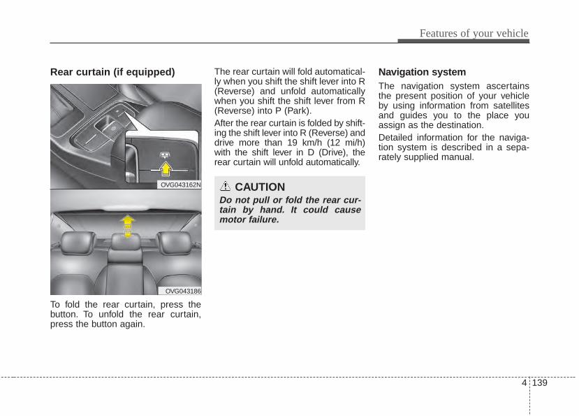
4 139
Features of your vehicle
Rear curtain (if equipped)
To fold the rear curtain, press thebutton. To unfold the rear curtain,press the button again.
The rear curtain will fold automatical-ly when you shift the shift lever into R(Reverse) and unfold automaticallywhen you shift the shift lever from R(Reverse) into P (Park).After the rear curtain is folded by shift-ing the shift lever into R (Reverse) anddrive more than 19 km/h (12 mi/h)with the shift lever in D (Drive), therear curtain will unfold automatically.
Navigation systemThe navigation system ascertainsthe present position of your vehicleby using information from satellitesand guides you to the place youassign as the destination.Detailed information for the naviga-tion system is described in a sepa-rately supplied manual.
CAUTIONDo not pull or fold the rear cur-tain by hand. It could causemotor failure.
OVG043162N
OVG043186
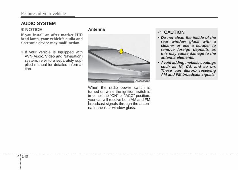
Features of your vehicle
1404
✽✽ NOTICE If you install an after market HIDhead lamp, your vehicle’s audio andelectronic device may malfunction.
❈ If your vehicle is equipped withAVN(Audio, Video and Navigation)system, refer to a separately sup-plied manual for detailed informa-tion.
Antenna
When the radio power switch isturned on while the ignition switch isin either the “ON” or “ACC” position,your car will receive both AM and FMbroadcast signals through the anten-na in the rear window glass.
AUDIO SYSTEM
CAUTION• Do not clean the inside of the
rear window glass with acleaner or use a scraper toremove foreign deposits asthis may cause damage to theantenna elements.
• Avoid adding metallic coatingssuch as Ni, Cd, and so on.These can disturb receivingAM and FM broadcast signals.
OVG049185
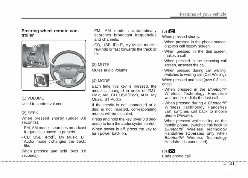
4 141
Features of your vehicle
Steering wheel remote con-troller
(1) VOLUMEUsed to control volume.
(2) SEEKWhen pressed shortly (under 0.8seconds).- FM, AM mode : searches broadcast
frequencies saved to presets.- CD, USB, iPod®, My Music, BT
Audio mode : changes the track,file.
When pressed and held (over 0.8seconds).
- FM, AM mode : automaticallysearches broadcast frequenciesand channels.
- CD, USB, iPod®, My Music mode :rewinds or fast forwards the track orfile.
(3) MUTEMutes audio volume.
(4) MODEEach time this key is pressed, themode is changed in order of FM1,FM2, AM, CD, USB(iPod), AUX, MyMusic, BT Audio.If the media is not connected or adisc is not inserted, correspondingmodes will be disabled.Press and hold the key (over 0.8 sec-onds) to turn the audio system on/off.When power is off, press the key toturn power back on.
(5) When pressed shortly.- When pressed in the phone screen,
displays call history screen.- When pressed in the dial screen,
makes a call.- When pressed in the incoming call
screen, answers the call.- When pressed during call waiting,
switches to waiting call (Call Waiting).When pressed and held (over 0.8 sec-onds).- When pressed in the Bluetooth®
Wireless Technology Handsfreewait mode, redials the last call.
- When pressed during a Bluetooth®
Wireless Technology Handsfreecall, switches call back to mobilephone (Private).
- When pressed while calling on themobile phone, switches call back toBluetooth® Wireless TechnologyHandsfree (Operates only whenBluetooth® Wireless TechnologyHandsfree is connected).
(6) Ends phone call.
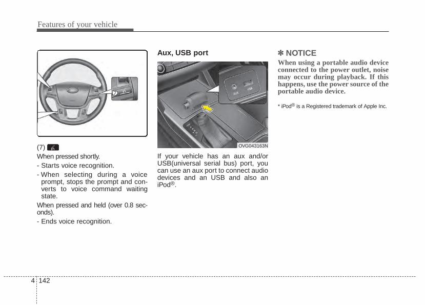
Features of your vehicle
1424
(7) When pressed shortly.- Starts voice recognition.- When selecting during a voice
prompt, stops the prompt and con-verts to voice command waitingstate.
When pressed and held (over 0.8 sec-onds).- Ends voice recognition.
Aux, USB port
If your vehicle has an aux and/orUSB(universal serial bus) port, youcan use an aux port to connect audiodevices and an USB and also aniPod®.
✽✽ NOTICEWhen using a portable audio deviceconnected to the power outlet, noisemay occur during playback. If thishappens, use the power source of theportable audio device.
* iPod® is a Registered trademark of Apple Inc.
OVG043163N
Driving your vehicle
Before driving . . . . . . . . . . . . . . . . . . . . . . . . . . . . . . 5-3Engine start/stop button . . . . . . . . . . . . . . . . . . . . . 5-5
• Illuminated ENGINE START/STOP button . . . . . . . 5-5• ENGINE START/STOP button position. . . . . . . . . . . 5-5
Starting the engine . . . . . . . . . . . . . . . . . . . . . . . . . . 5-8Automatic transaxle . . . . . . . . . . . . . . . . . . . . . . . . 5-10
• Automatic transaxle operation . . . . . . . . . . . . . . . . . . 5-10Brake system. . . . . . . . . . . . . . . . . . . . . . . . . . . . . . 5-16
• Power brakes . . . . . . . . . . . . . . . . . . . . . . . . . . . . . . . 5-16• Parking brake (foot type) . . . . . . . . . . . . . . . . . . . . . . 5-17• Electric parking brake (EPB) . . . . . . . . . . . . . . . . . . 5-19• Auto hold . . . . . . . . . . . . . . . . . . . . . . . . . . . . . . . . . . . 5-25• Anti-lock brake system (ABS) . . . . . . . . . . . . . . . . . . 5-28• Electronic stability control (ESC) . . . . . . . . . . . . . . . 5-30• Hill-start assist control (HAC) . . . . . . . . . . . . . . . . . . 5-33• Vehicle stability management (VSM) . . . . . . . . . . . . 5-34
Cruise control system. . . . . . . . . . . . . . . . . . . . . . . 5-37Smart cruise control (SCC) system . . . . . . . . . . . 5-41Lane departure warning system (LDWS) . . . . . . 5-55Blind spot detection system (BSD) . . . . . . . . . . . . 5-59Economical operation . . . . . . . . . . . . . . . . . . . . . . 5-64Special driving conditions . . . . . . . . . . . . . . . . . . . 5-66
• Hazardous driving conditions . . . . . . . . . . . . . . . . . . 5-66• Rocking the vehicle . . . . . . . . . . . . . . . . . . . . . . . . . . . 5-66
• Smooth cornering . . . . . . . . . . . . . . . . . . . . . . . . . . . . 5-67• Driving at night . . . . . . . . . . . . . . . . . . . . . . . . . . . . . . 5-67• Driving in the rain. . . . . . . . . . . . . . . . . . . . . . . . . . . . 5-68• Driving in flooded areas . . . . . . . . . . . . . . . . . . . . . . . 5-68• Driving off-road. . . . . . . . . . . . . . . . . . . . . . . . . . . . . . 5-69• Highway driving . . . . . . . . . . . . . . . . . . . . . . . . . . . . . 5-69
Winter driving . . . . . . . . . . . . . . . . . . . . . . . . . . . . 5-70Vehicle load limit . . . . . . . . . . . . . . . . . . . . . . . . . . 5-73
• Tire and loading information label . . . . . . . . . . . . . . 5-73• Certification label . . . . . . . . . . . . . . . . . . . . . . . . . . . . 5-76
Vehicle weight . . . . . . . . . . . . . . . . . . . . . . . . . . . . . 5-78• Base curb weight . . . . . . . . . . . . . . . . . . . . . . . . . . . . . 5-78• Vehicle curb weight . . . . . . . . . . . . . . . . . . . . . . . . . . . 5-78• Cargo weight . . . . . . . . . . . . . . . . . . . . . . . . . . . . . . . . 5-78• GAW (Gross axle weight) . . . . . . . . . . . . . . . . . . . . . . 5-78• GAWR (Gross axle weight rating) . . . . . . . . . . . . . . . 5-78• GVW (Gross vehicle weight) . . . . . . . . . . . . . . . . . . . 5-78• GVWR (Gross vehicle weight rating) . . . . . . . . . . . . 5-78
5
Driving your vehicle
25
Be sure the exhaust systemdoes not leak.The exhaust system should bechecked whenever the vehicle israised to change the oil or for anyother purpose. If youhear a change in the sound of theexhaust or if you drive over some-thing that strikes the underneath sideof the vehicle, have the exhaust sys-tem checked as soon as possible byan authorized Kia dealer.
WARNING - Engineexhaust
Do not inhale exhaust fumes orleave your engine running in anenclosed area for a prolongedtime.Exhaust fumes contain carbonmonoxide, a colorless, odorlessgas that can cause uncon-sciousness and death byasphyxiation.
WARNING - Open trunkDo not drive with the trunkopen.Poisonous exhaust gases canenter the passenger compart-ment. If you must drive with thetrunk open proceed as follows:1.Close all windows.2.Open side vents.3.Set the air intake control at
"Fresh", the air flow control at"Floor" or "Face" and the fanat the highest speed.
Before entering vehicle• Be sure that all windows, outside
mirror(s), and outside lights areclean.
• Check the condition of the tires.• Check under the vehicle for any
sign of leaks.• Be sure there are no obstacles
behind you if you intend to back up.
Necessary inspections Fluid levels, such as engine oil,engine coolant, brake fluid, andwasher fluid should be checked on aregular basis, with the exact intervaldepending on the fluid. Furtherdetails are provided in Section 7,“Maintenance”.
Before starting • Close and lock all doors.• Position the seat so that all con-
trols are easily reached.• Buckle your seat belt.• Adjust the inside and outside
rearview mirrors.• Be sure that all lights work.• Check all gauges.• Check the operation of warning
lights when the ignition switch isturned to the ON position.
• Release the parking brake andmake sure the brake warning lightgoes off.
For safe operation, be sure you arefamiliar with your vehicle and itsequipment.
BEFORE DRIVING
5 3
Driving your vehicle
WARNING - Distracteddriving
Focus on the road while driving.The driver's primary responsi-bility is in the safe and legaloperation of the vehicle. Use ofany hand held devices, otherequipment or vehicle systemsthat distract the driver shouldnot be used during vehicleoperation.
WARNING - Check surrounding
Always check the surroundingareas near your vehicle for peo-ple, especially children, beforeputting a vehicle into D (Drive)or R (Reverse).
Driving your vehicle
45
WARNING - Fire riskWhen you intend to park or stopthe vehicle with the engine on,be careful not to depress theaccelerator pedal for a longperiod of time. It may overheatthe engine or exhaust systemand cause a fire.
WARNING - Drivingwhile intoxi-cated
Do not drive while intoxicated.Drinking and driving is danger-ous. Even a small amount ofalcohol will affect your reflexes,perceptions and judgment.Driving while under the influ-ence of drugs is as dangerousas or more dangerous than driv-ing drunk.
WARNING - Looseobject
Securely store items in yourvehicle. When you make a sud-den stop or turn the steeringwheel rapidly, loose objectsmay drop on the floor and itcould interfere with the opera-tion of the foot pedals, possiblycausing an accident.
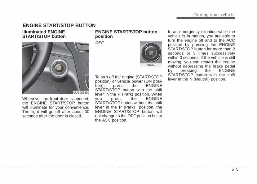
5 5
Driving your vehicle
Illuminated ENGINESTART/STOP button
Whenever the front door is opened,the ENGINE START/STOP buttonwill illuminate for your convenience.The light will go off after about 30seconds after the door is closed.
ENGINE START/STOP buttonpositionOFF
To turn off the engine (START/STOPposition) or vehicle power (ON posi-tion), press the ENGINESTART/STOP button with the shiftlever in the P (Park) position. Whenyou press the ENGINESTART/STOP button without the shiftlever in the P (Park) position, theENGINE START/STOP button willnot change to the OFF position but tothe ACC position.
In an emergency situation while thevehicle is in motion, you are able toturn the engine off and to the ACCposition by pressing the ENGINESTART/STOP button for more than 2seconds or 3 times successivelywithin 3 seconds. If the vehicle is stillmoving, you can restart the enginewithout depressing the brake pedalby pressing the ENGINESTART/STOP button with the shiftlever in the N (Neutral) position.
ENGINE START/STOP BUTTON
OVG053300
White
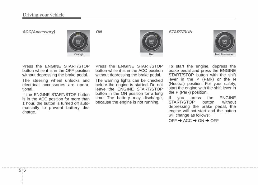
Driving your vehicle
65
ACC(Accessory)
Press the ENGINE START/STOPbutton while it is in the OFF positionwithout depressing the brake pedal.The steering wheel unlocks andelectrical accessories are opera-tional.If the ENGINE START/STOP buttonis in the ACC position for more than1 hour, the button is turned off auto-matically to prevent battery dis-charge.
ON
Press the ENGINE START/STOPbutton while it is in the ACC positionwithout depressing the brake pedal.The warning lights can be checkedbefore the engine is started. Do notleave the ENGINE START/STOPbutton in the ON position for a longtime. The battery may discharge,because the engine is not running.
START/RUN
To start the engine, depress thebrake pedal and press the ENGINESTART/STOP button with the shiftlever in the P (Park) or the N(Nuetral) position. For your safety,start the engine with the shift lever inthe P (Park) position.If you press the ENGINESTART/STOP button withoutdepressing the brake pedal, theengine will not start and the buttonwill change as follows:OFF ➔ ACC ➔ ON ➔ OFF
Orange Red Not illuminated
5 7
Driving your vehicle
If you leave the ENGINE START/STOP button in the ACC or ON posi-tion for a long time, the battery willdischarge.
WARNING - Starting vehicle
Never press the ENGINESTART/STOP button while thevehicle is in motion. This wouldresult in loss of directional con-trol and braking function, whichcould cause an accident.
Driving your vehicle
85
Starting the engine with asmart key1.Carry the smart key or leave it
inside the vehicle.2.Make sure the parking brake is
firmly applied3.Place the transaxle shift lever in P
(Park).4.Press the ENGINE START/STOP
button while depressing the brakepedal.
5.In extremely cold weather (below0°F / -18°C) or after the vehicle hasnot been operated for several days,let the engine warm up withoutdepressing the accelerator.
Whether the engine is cold or warm,it should be started without depress-ing the accelerator.• Even if the smart key is in the vehi-
cle, but is far away from you, theengine may not start.
• When the ENGINE START/STOPbutton is in the ACC position orabove, if any door is opened, thesystem checks for the smart key. Ifthe smart key is not in the vehi-cle,the “ ” indicator will blink orthe warning "Key not in vehicle" willilluminate on the LCD display. Andif all doors are closed, the chimewill sound for 5 seconds. The indi-cator or warning will turn off whilethe vehicle is moving. Always havethe smart key with you.
The engine will start only when thesmart key is in the vehicle.
STARTING THE ENGINE
WARNING - Properfootwear
Always wear appropriate shoeswhen operating your vehicle.Unsuitable shoes (high heels,ski boots, sandals, etc.) mayinterfere with your ability to usethe brake and accelerator ped-als.
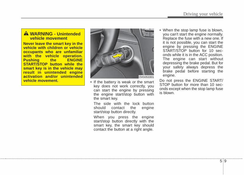
5 9
Driving your vehicle
• If the battery is weak or the smartkey does not work correctly, youcan start the engine by pressingthe engine start/stop button withthe smart key.The side with the lock buttonshould contact the enginestart/stop button directly.When you press the enginestart/stop button directly with thesmart key, the smart key shouldcontact the button at a right angle.
• When the stop lamp fuse is blown,you can't start the engine normally.Replace the fuse with a new one. Ifit is not possible, you can start theengine by pressing the ENGINESTART/STOP button for 10 sec-onds while it is in the ACC position.The engine can start withoutdepressing the brake pedal. But foryour safety always depress thebrake pedal before starting theengine.
Do not press the ENGINE START/STOP button for more than 10 sec-onds except when the stop lamp fuseis blown.
WARNING - Unintendedvehicle movement
Never leave the smart key in thevehicle with children or vehicleoccupants who are unfamiliarwith the vehicle operation.Pushing the ENGINESTART/STOP button while thesmart key is in the vehicle mayresult in unintended engineactivation and/or unintendedvehicle movement.
OVG053301
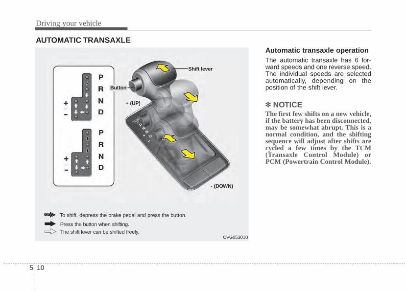
Driving your vehicle
105
Automatic transaxle operationThe automatic transaxle has 6 for-ward speeds and one reverse speed.The individual speeds are selectedautomatically, depending on theposition of the shift lever.
✽✽ NOTICEThe first few shifts on a new vehicle,if the battery has been disconnected,may be somewhat abrupt. This is anormal condition, and the shiftingsequence will adjust after shifts arecycled a few times by the TCM(Transaxle Control Module) orPCM (Powertrain Control Module).
AUTOMATIC TRANSAXLE
OVG053010
+ (UP)
Shift lever
- (DOWN)
To shift, depress the brake pedal and press the button.
The shift lever can be shifted freely.
Press the button when shifting.
Button
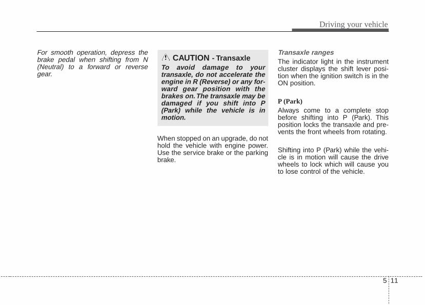
5 11
Driving your vehicle
For smooth operation, depress thebrake pedal when shifting from N(Neutral) to a forward or reversegear.
When stopped on an upgrade, do nothold the vehicle with engine power.Use the service brake or the parkingbrake.
Transaxle rangesThe indicator light in the instrumentcluster displays the shift lever posi-tion when the ignition switch is in theON position.
P (Park)Always come to a complete stopbefore shifting into P (Park). Thisposition locks the transaxle and pre-vents the front wheels from rotating.
Shifting into P (Park) while the vehi-cle is in motion will cause the drivewheels to lock which will cause youto lose control of the vehicle.
CAUTION - TransaxleTo avoid damage to yourtransaxle, do not accelerate theengine in R (Reverse) or any for-ward gear position with thebrakes on.The transaxle may bedamaged if you shift into P(Park) while the vehicle is inmotion.
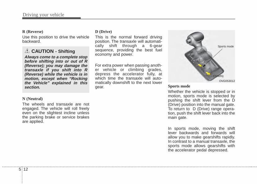
Driving your vehicle
125
R (Reverse)Use this position to drive the vehiclebackward.
N (Neutral)The wheels and transaxle are notengaged. The vehicle will roll freelyeven on the slightest incline unlessthe parking brake or service brakesare applied.
D (Drive)This is the normal forward drivingposition. The transaxle will automati-cally shift through a 6-gearsequence, providing the best fueleconomy and power.
For extra power when passing anoth-er vehicle or climbing grades,depress the accelerator fully, atwhich time the transaxle will auto-matically downshift to the next lowergear. Sports mode
Whether the vehicle is stopped or inmotion, sports mode is selected bypushing the shift lever from the D(Drive) position into the manual gate.To return to D (Drive) range opera-tion, push the shift lever back into themain gate.
In sports mode, moving the shiftlever backwards and forwards willallow you to make gearshifts rapidly.In contrast to a manual transaxle, thesports mode allows gearshifts withthe accelerator pedal depressed.
CAUTION - ShiftingAlways come to a complete stopbefore shifting into or out of R(Reverse); you may damage thetransaxle if you shift into R(Reverse) while the vehicle is inmotion, except when “Rockingthe Vehicle” explained in thissection.
OVG053012
++++ ((((UUUUPPPP))))
- (DOWN)
Sports mode
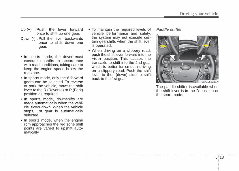
5 13
Driving your vehicle
Up (+) : Push the lever forwardonce to shift up one gear.
Down (-) : Pull the lever backwardsonce to shift down onegear.
• In sports mode, the driver mustexecute upshifts in accordancewith road conditions, taking care tokeep the engine speed below thered zone.
• In sports mode, only the 6 forwardgears can be selected. To reverseor park the vehicle, move the shiftlever to the R (Reverse) or P (Park)position as required.
• In sports mode, downshifts aremade automatically when the vehi-cle slows down. When the vehiclestops, 1st gear is automaticallyselected.
• In sports mode, when the enginerpm approaches the red zone shiftpoints are varied to upshift auto-matically.
• To maintain the required levels ofvehicle performance and safety,the system may not execute cer-tain gearshifts when the shift leveris operated.
• When driving on a slippery road,push the shift lever forward into the+(up) position. This causes thetransaxle to shift into the 2nd gearwhich is better for smooth drivingon a slippery road. Push the shiftlever to the -(down) side to shiftback to the 1st gear.
Paddle shifter
The paddle shifter is available whenthe shift lever is in the D position orthe sport mode.
OVG053331N
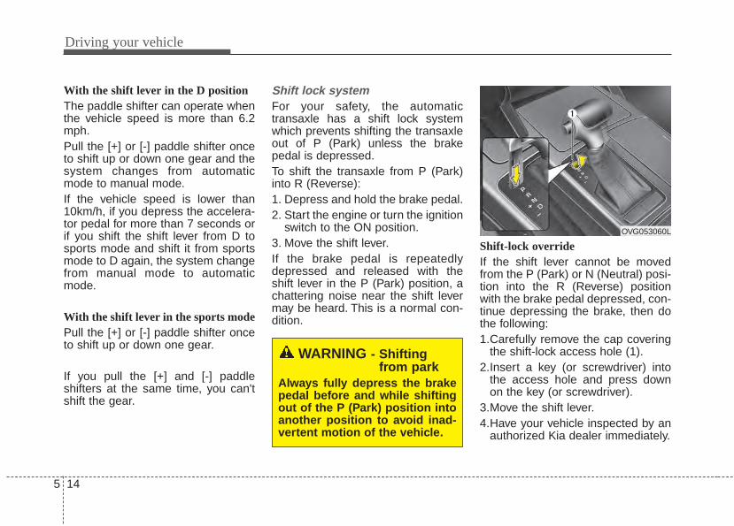
Driving your vehicle
145
With the shift lever in the D position The paddle shifter can operate whenthe vehicle speed is more than 6.2mph.Pull the [+] or [-] paddle shifter onceto shift up or down one gear and thesystem changes from automaticmode to manual mode.If the vehicle speed is lower than10km/h, if you depress the accelera-tor pedal for more than 7 seconds orif you shift the shift lever from D tosports mode and shift it from sportsmode to D again, the system changefrom manual mode to automaticmode.
With the shift lever in the sports mode Pull the [+] or [-] paddle shifter onceto shift up or down one gear.
If you pull the [+] and [-] paddleshifters at the same time, you can'tshift the gear.
Shift lock systemFor your safety, the automatictransaxle has a shift lock systemwhich prevents shifting the transaxleout of P (Park) unless the brakepedal is depressed.To shift the transaxle from P (Park)into R (Reverse):1. Depress and hold the brake pedal.2. Start the engine or turn the ignition
switch to the ON position.3. Move the shift lever.If the brake pedal is repeatedlydepressed and released with theshift lever in the P (Park) position, achattering noise near the shift levermay be heard. This is a normal con-dition.
Shift-lock overrideIf the shift lever cannot be movedfrom the P (Park) or N (Neutral) posi-tion into the R (Reverse) positionwith the brake pedal depressed, con-tinue depressing the brake, then dothe following:1.Carefully remove the cap covering
the shift-lock access hole (1).2.Insert a key (or screwdriver) into
the access hole and press downon the key (or screwdriver).
3.Move the shift lever.4.Have your vehicle inspected by an
authorized Kia dealer immediately.
WARNING - Shiftingfrom park
Always fully depress the brakepedal before and while shiftingout of the P (Park) position intoanother position to avoid inad-vertent motion of the vehicle.
OVG053060L
5 15
Driving your vehicle
Good driving practices• Never move the shift lever from P
(Park) or N (Neutral) to any otherposition with the accelerator pedaldepressed.
• Never move the shift lever into P(Park) when the vehicle is inmotion.
• Slow down before shifting to alower gear. Otherwise, the lowergear may not be engaged.
• Always use the parking brake. Donot depend on placing thetransaxle in P (Park) to keep thevehicle from moving.
• Optimum vehicle performance andeconomy is obtained by smoothlydepressing and releasing theaccelerator pedal.
Moving up a steep grade from astanding startTo move up a steep grade from astanding start, depress the brakepedal, shift the shift lever to D(Drive). Select the appropriate geardepending on load weight and steep-ness of the grade, and release theparking brake. Depress the accelera-tor gradually while releasing theservice brakes.
Driving your vehicle
165
Power brakes Your vehicle has power-assistedbrakes that adjust automaticallythrough normal usage.In the event that the power-assistedbrakes lose power because of astalled engine or some other reason,you can still stop your vehicle byapplying greater force to the brakepedal than you normally would. Thestopping distance, however, will belonger.When the engine is not running, thereserve brake power is partiallydepleted each time the brake pedalis applied. Do not pump the brakepedal when the power assist hasbeen interrupted.Pump the brake pedal only whennecessary to maintain steering con-trol on slippery surfaces.
Wet brakes may impair the vehicle’sability to safely slow down; the vehi-cle may also pull to one side whenthe brakes are applied. Applying thebrakes lightly will indicate whetherthey have been affected in this way.
To dry the brakes, apply them lightlywhile maintaining a safe forwardspeed until brake performancereturns to normal.
In the event of brake failure If service brakes fail to operate whilethe vehicle is in motion, you canmake an emergency stop with theparking brake. The stopping dis-tance, however, will be much greaterthan normal.
BRAKE SYSTEM
WARNING - Parkingbrake
Avoid applying the parkingbrake to stop the vehicle while itis moving except in an emer-gency situation. Applying theparking brake while the vehicleis moving at normal speeds cancause a sudden loss of controlof the vehicle. If you must usethe parking brake to stop thevehicle, use great caution inapplying the brake.
WARNING - Steep hillbraking
Avoid continuous application ofthe brakes when descending along or steep hill by shifting to alower gear. Continuous brakeapplication will cause thebrakes to overheat and couldresult in a temporary loss ofbraking performance.
CAUTION - Brake pedalDo not drive with your foot rest-ing on the brake pedal. This willcreate abnormally high braketemperatures which can causeexcessive brake lining and padwear.
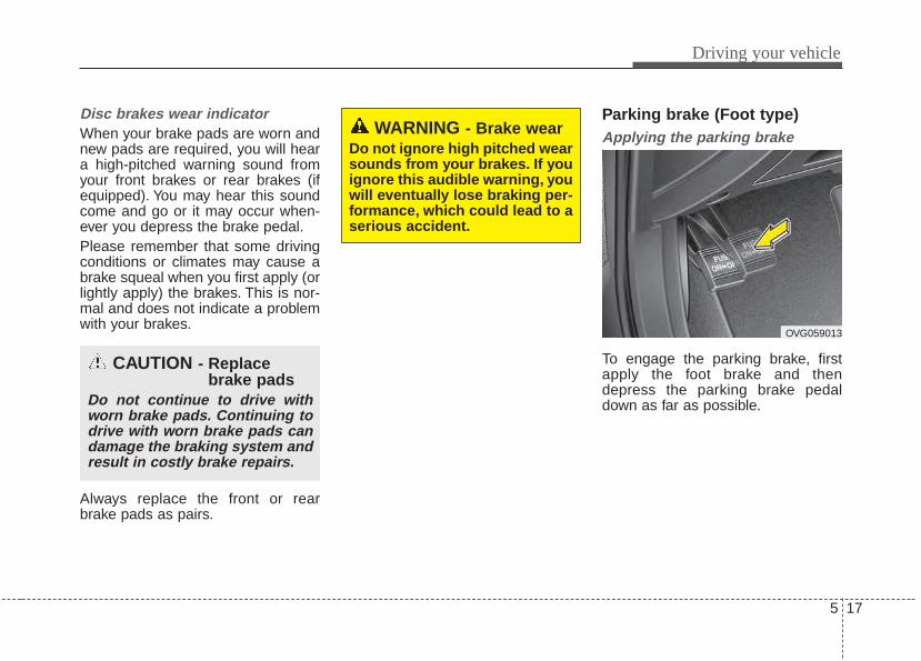
5 17
Driving your vehicle
Disc brakes wear indicator When your brake pads are worn andnew pads are required, you will heara high-pitched warning sound fromyour front brakes or rear brakes (ifequipped). You may hear this soundcome and go or it may occur when-ever you depress the brake pedal.Please remember that some drivingconditions or climates may cause abrake squeal when you first apply (orlightly apply) the brakes. This is nor-mal and does not indicate a problemwith your brakes.
Always replace the front or rearbrake pads as pairs.
Parking brake (Foot type) Applying the parking brake
To engage the parking brake, firstapply the foot brake and thendepress the parking brake pedaldown as far as possible.
CAUTION - Replacebrake pads
Do not continue to drive withworn brake pads. Continuing todrive with worn brake pads candamage the braking system andresult in costly brake repairs.
OVG059013
WARNING - Brake wearDo not ignore high pitched wearsounds from your brakes. If youignore this audible warning, youwill eventually lose braking per-formance, which could lead to aserious accident.
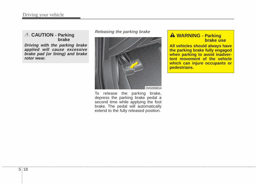
Driving your vehicle
185
Releasing the parking brake
To release the parking brake,depress the parking brake pedal asecond time while applying the footbrake. The pedal will automaticallyextend to the fully released position.
CAUTION - Parkingbrake
Driving with the parking brakeapplied will cause excessivebrake pad (or lining) and brakerotor wear.
OVG059014
WARNING - Parkingbrake use
All vehicles should always havethe parking brake fully engagedwhen parking to avoid inadver-tent movement of the vehiclewhich can injure occupants orpedestrians.
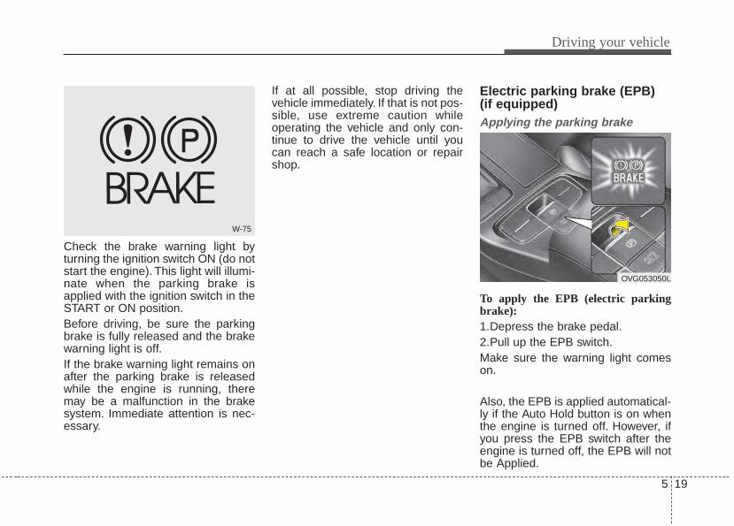
5 19
Driving your vehicle
Check the brake warning light byturning the ignition switch ON (do notstart the engine). This light will illumi-nate when the parking brake isapplied with the ignition switch in theSTART or ON position.Before driving, be sure the parkingbrake is fully released and the brakewarning light is off.If the brake warning light remains onafter the parking brake is releasedwhile the engine is running, theremay be a malfunction in the brakesystem. Immediate attention is nec-essary.
If at all possible, stop driving thevehicle immediately. If that is not pos-sible, use extreme caution whileoperating the vehicle and only con-tinue to drive the vehicle until youcan reach a safe location or repairshop.
Electric parking brake (EPB) (if equipped)Applying the parking brake
To apply the EPB (electric parkingbrake):1.Depress the brake pedal.2.Pull up the EPB switch.Make sure the warning light comeson.
Also, the EPB is applied automatical-ly if the Auto Hold button is on whenthe engine is turned off. However, ifyou press the EPB switch after theengine is turned off, the EPB will notbe Applied.
W-75
OVG053050L
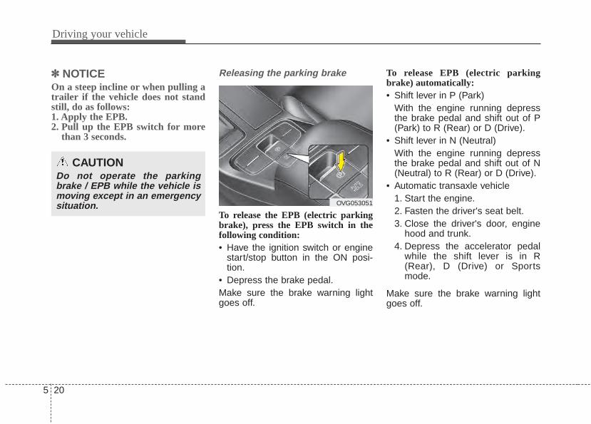
Driving your vehicle
205
✽✽ NOTICEOn a steep incline or when pulling atrailer if the vehicle does not standstill, do as follows:1. Apply the EPB.2. Pull up the EPB switch for more
than 3 seconds.
Releasing the parking brake
To release the EPB (electric parkingbrake), press the EPB switch in thefollowing condition:• Have the ignition switch or engine
start/stop button in the ON posi-tion.
• Depress the brake pedal.Make sure the brake warning lightgoes off.
To release EPB (electric parkingbrake) automatically:• Shift lever in P (Park)
With the engine running depressthe brake pedal and shift out of P(Park) to R (Rear) or D (Drive).
• Shift lever in N (Neutral)With the engine running depressthe brake pedal and shift out of N(Neutral) to R (Rear) or D (Drive).
• Automatic transaxle vehicle1. Start the engine.2. Fasten the driver's seat belt.3. Close the driver's door, engine
hood and trunk.4. Depress the accelerator pedal
while the shift lever is in R(Rear), D (Drive) or Sportsmode.
Make sure the brake warning lightgoes off.
CAUTIONDo not operate the parkingbrake / EPB while the vehicle ismoving except in an emergencysituation. OVG053051
5 21
Driving your vehicle
✽✽ NOTICE• For your safety, you can engage
the EPB even though the ignitionswitch or engine stop/start buttonis in the OFF position, but youcannot release it.
• For your safety, depress the brakepedal and release the parkingbrake manually with the EPBswitch when you drive downhill orwhen backing up the vehicle.
EPB (electric parking brake) may beautomatically applied when: • Requested by other systems
✽✽ NOTICEIf the driver turns the engine off bymistake while Auto Hold is operat-ing, EPB will be automaticallyapplied. (Vehicles equipped withAuto Hold)
• If the driver's seat belt is not fas-tened and the engine hood or trunkis opened, a warning will soundand a message will appear.
• If there is a problem with the vehi-cle, a warning may sound and amessage may appear.
If the above situation occurs,depress the brake pedal and releaseEPB by pressing the EPB switch.
CAUTION• If the parking brake warning
light is still on even thoughthe EPB has been released,have the system checked byan authorized Kia dealer.
• Do not drive your vehicle withthe EPB applied. It may causeexcessive brake pad andbrake rotor wear.
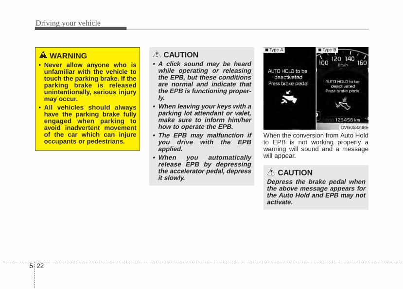
Driving your vehicle
225
When the conversion from Auto Holdto EPB is not working properly awarning will sound and a messagewill appear.
WARNING• Never allow anyone who is
unfamiliar with the vehicle totouch the parking brake. If theparking brake is releasedunintentionally, serious injurymay occur.
• All vehicles should alwayshave the parking brake fullyengaged when parking toavoid inadvertent movementof the car which can injureoccupants or pedestrians.
CAUTION• A click sound may be heard
while operating or releasingthe EPB, but these conditionsare normal and indicate thatthe EPB is functioning proper-ly.
• When leaving your keys with aparking lot attendant or valet,make sure to inform him/herhow to operate the EPB.
• The EPB may malfunction ifyou drive with the EPBapplied.
• When you automaticallyrelease EPB by depressingthe accelerator pedal, depressit slowly.
OVG053308E
■ Type A ■ Type B
CAUTIONDepress the brake pedal whenthe above message appears forthe Auto Hold and EPB may notactivate.
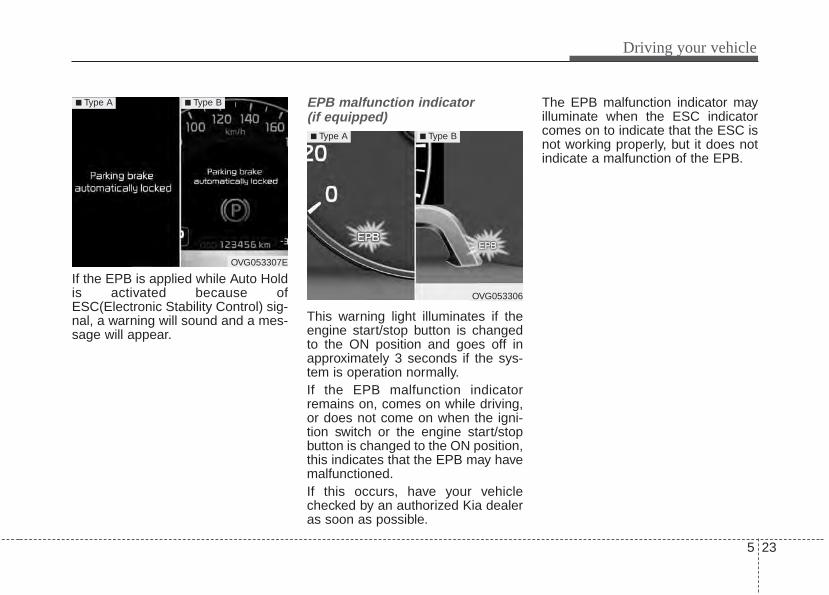
5 23
Driving your vehicle
If the EPB is applied while Auto Holdis activated because ofESC(Electronic Stability Control) sig-nal, a warning will sound and a mes-sage will appear.
EPB malfunction indicator (if equipped)
This warning light illuminates if theengine start/stop button is changedto the ON position and goes off inapproximately 3 seconds if the sys-tem is operation normally.If the EPB malfunction indicatorremains on, comes on while driving,or does not come on when the igni-tion switch or the engine start/stopbutton is changed to the ON position,this indicates that the EPB may havemalfunctioned.If this occurs, have your vehiclechecked by an authorized Kia dealeras soon as possible.
The EPB malfunction indicator mayilluminate when the ESC indicatorcomes on to indicate that the ESC isnot working properly, but it does notindicate a malfunction of the EPB.
OVG053307E
■ Type A ■ Type B
OVG053306
■ Type A ■ Type B
Driving your vehicle
245
Emergency brakingIf there is a problem with the brakepedal while driving, emergency brak-ing is possible by pulling up andholding the EPB switch. Braking ispossible only while you are holdingthe EPB switch.
✽✽ NOTICEDuring emergency braking by theEPB, the parking brake warninglight will illuminate to indicate thatthe system is operating.
CAUTION• The EPB warning light may
illuminate if the EPB switchoperates abnormally. Shut theengine off and turn it on againafter a few minutes. The warn-ing light will go off and theEPB switch will operate nor-mally. However, if the EPBwarning light is still on, havethe system checked by anauthorized Kia dealer.
• If the parking brake warninglight does not illuminate orblinks even though the EPBswitch was pulled up, the EPBis not applied.
• If the parking brake warninglight blinks when the EPBwarning light is on, press theswitch, then pull it up. Oncemore press it back to its origi-nal position and pull it backup. If the EPB warning doesnot go off, have the systemchecked by an authorized Kiadealer.
WARNINGDo not operate the electric park-ing brake while the vehicle ismoving except in an emergencysituation. Applying the electricparking brake while the vehicleis moving at normal speeds cancause a sudden loss of controlof the vehicle. If you must usethe electric parking brake tostop the vehicle, use great cau-tion in applying the brake.
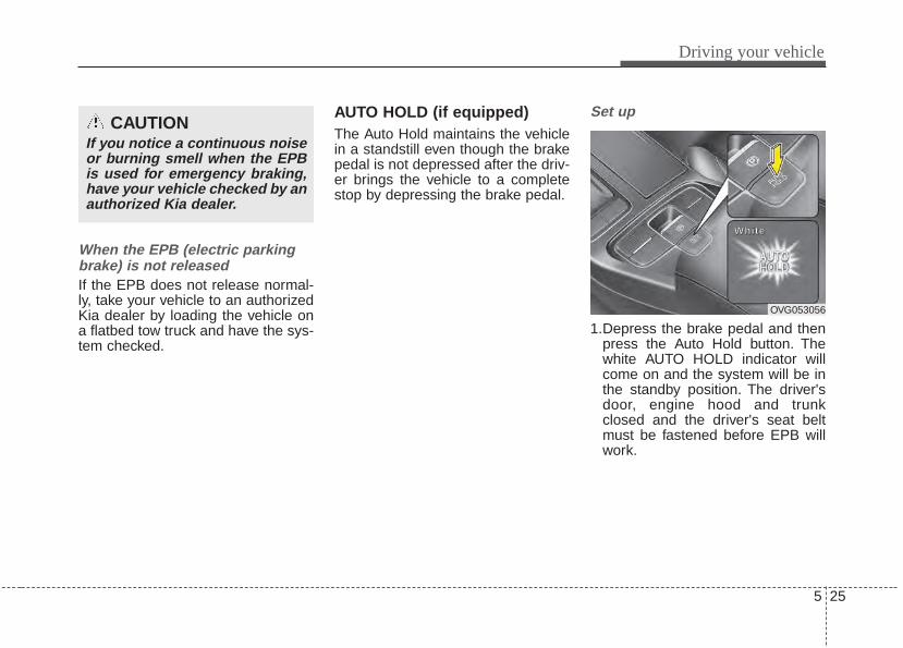
5 25
Driving your vehicle
When the EPB (electric parkingbrake) is not releasedIf the EPB does not release normal-ly, take your vehicle to an authorizedKia dealer by loading the vehicle ona flatbed tow truck and have the sys-tem checked.
AUTO HOLD (if equipped)The Auto Hold maintains the vehiclein a standstill even though the brakepedal is not depressed after the driv-er brings the vehicle to a completestop by depressing the brake pedal.
Set up
1.Depress the brake pedal and thenpress the Auto Hold button. Thewhite AUTO HOLD indicator willcome on and the system will be inthe standby position. The driver'sdoor, engine hood and trunkclosed and the driver's seat beltmust be fastened before EPB willwork.
CAUTIONIf you notice a continuous noiseor burning smell when the EPBis used for emergency braking,have your vehicle checked by anauthorized Kia dealer.
OVG053056
WWWWhhhhiiii tttteeee
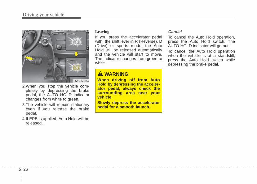
Driving your vehicle
265
2.When you stop the vehicle com-pletely by depressing the brakepedal, the AUTO HOLD indicatorchanges from white to green.
3.The vehicle will remain stationaryeven if you release the brakepedal.
4.If EPB is applied, Auto Hold will bereleased.
LeavingIf you press the accelerator pedalwith the shift lever in R (Reverse), D(Drive) or sports mode, the AutoHold will be released automaticallyand the vehicle will start to move.The indicator changes from green towhite.
CancelTo cancel the Auto Hold operation,press the Auto Hold switch. TheAUTO HOLD indicator will go out.To cancel the Auto Hold operationwhen the vehicle is at a standstill,press the Auto Hold switch whiledepressing the brake pedal.
OVG053057
WWWWhhhhiiii tttteeee
GGGGrrrreeeeeeeennnn
WARNINGWhen driving off from AutoHold by depressing the acceler-ator pedal, always check thesurrounding area near yourvehicle.Slowly depress the acceleratorpedal for a smooth launch.
5 27
Driving your vehicle
✽✽ NOTICE• The Auto Hold does not operate
when:- The driver's seat belt is unfas-
tened and driver's door is opened- The engine hood is opened- The trunk is opened- The shift lever is in P (Park)- The EPB is applied
• For your safety, the Auto Holdautomatically switches to EPB insuch cases:- The driver's seat belt is unfas-
tened and driver's door is opened- The engine hood is opened- The trunk is opened- The vehicle is in a standstill for
more than 10 minutes- The vehicle is standing on a steep
slope- The vehicle moved several times
(Continued)
(Continued)In these cases, the brake warninglight comes on, the AUTO HOLDindicator changes from green towhite, and a warning sounds and amessage will appear to inform youthat EPB has been automaticallyengaged. Before driving off again,press foot brake pedal, check thesurrounding area near your vehi-cle and release parking brakemanually with the EPB switch.
• If the AUTO HOLD indicatorlights up yellow, the Auto Hold isnot working properly. Take yourvehicle to an authorized Kia deal-er and have the system checked.
• While operating Auto Hold, youmay hear mechanical noise.However, it is normal operatingnoise.
WARNINGFor your safety, cancel the AutoHold when you drive downhill orback up the vehicle or park thevehicle.
CAUTIONIf there is a malfunction with thedriver’s door, engine hood ortrunk open detection system,the Auto Hold may not workproperly.Take your vehicle to an author-ized Kia dealer and have thesystem checked.
Driving your vehicle
285
Anti-lock brake system (ABS)ABS (or ESC) will not prevent acci-dents due to improper or dangerousdriving maneuvers. Even thoughvehicle control is improved duringemergency braking, always maintaina safe distance between you andobjects ahead. Vehicle speedsshould always be reduced duringextreme road conditions.The vehicle should be driven atreduced speeds in the following cir-cumstances:• When driving on rough, gravel or
snow-covered roads• When driving on roads where the
road surface is pitted or has differ-ent surface heights.
Driving in these conditions increasesthe stopping distance for your vehi-cle.
The ABS continuously senses thespeed of the wheels. If the wheelsare going to lock, the ABS systemrepeatedly modulates the hydraulicbrake pressure to the wheels.When you apply your brakes underconditions which may lock thewheels, you may hear a “tik-tik’’sound from the brakes, or feel a cor-responding sensation in the brakepedal. This is normal and it meansyour ABS is active.In order to obtain the maximum ben-efit from your ABS in an emergencysituation, do not attempt to modulateyour brake pressure and do not try topump your brakes. Press your brakepedal as hard as possible or as hardas the situation allows the ABS tocontrol the force being delivered tothe brakes.
✽✽ NOTICEA click sound may be heard in theengine compartment when the vehi-cle begins to move after the engine isstarted. These conditions are normaland indicate that the anti-lock brakesystem is functioning properly.
• Even with the anti-lock brake sys-tem, your vehicle still requires suf-ficient stopping distance. Alwaysmaintain a safe distance from thevehicle in front of you.
• Always slow down when cornering.The anti-lock brake system cannotprevent accidents resulting fromexcessive speeds.
• On loose or uneven road surfaces,operation of the anti-lock brakesystem may result in a longer stop-ping distance than for vehiclesequipped with a conventionalbrake system.

5 29
Driving your vehicle
The ABS warning light will stay on forapproximately 3 seconds after theignition switch is ON. During thattime, the ABS will go through self-diagnosis and the light will go off ifeverything is normal. If the light stayson, you may have a problem withyour ABS but your regular brakes willwork normally. Contact an authorizedKia dealer as soon as possible.
• When you drive on a road withpoor traction, such as an icy road,and operated your brakes continu-ously, the ABS will be active con-tinuously and the ABS warninglight may illuminate. Pull your vehi-cle over to a safe place and stopthe engine.
• Restart the engine. If the ABSwarning light is off, then your ABSis normal. Otherwise, you mayhave a problem with the ABS.Contact an authorized Kia dealeras soon as possible.
✽✽ NOTICEWhen you jump start your vehiclebecause of a drained battery, theengine may not run as smoothly andthe ABS warning light may turn onat the same time. This happensbecause of the low battery voltage. Itdoes not mean your ABS has mal-functioned.• Do not pump your brakes!• Have the battery recharged before
driving the vehicle.W-78
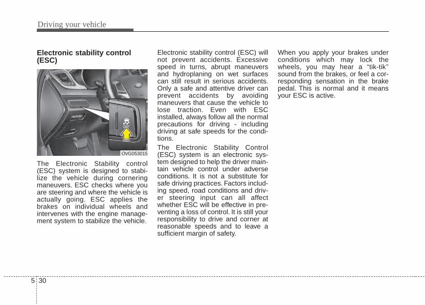
Driving your vehicle
305
Electronic stability control(ESC)
The Electronic Stability control(ESC) system is designed to stabi-lize the vehicle during corneringmaneuvers. ESC checks where youare steering and where the vehicle isactually going. ESC applies thebrakes on individual wheels andintervenes with the engine manage-ment system to stabilize the vehicle.
Electronic stability control (ESC) willnot prevent accidents. Excessivespeed in turns, abrupt maneuversand hydroplaning on wet surfacescan still result in serious accidents.Only a safe and attentive driver canprevent accidents by avoidingmaneuvers that cause the vehicle tolose traction. Even with ESCinstalled, always follow all the normalprecautions for driving - includingdriving at safe speeds for the condi-tions.The Electronic Stability Control(ESC) system is an electronic sys-tem designed to help the driver main-tain vehicle control under adverseconditions. It is not a substitute forsafe driving practices. Factors includ-ing speed, road conditions and driv-er steering input can all affectwhether ESC will be effective in pre-venting a loss of control. It is still yourresponsibility to drive and corner atreasonable speeds and to leave asufficient margin of safety.
When you apply your brakes underconditions which may lock thewheels, you may hear a “tik-tik’’sound from the brakes, or feel a cor-responding sensation in the brakepedal. This is normal and it meansyour ESC is active.
OVG053015
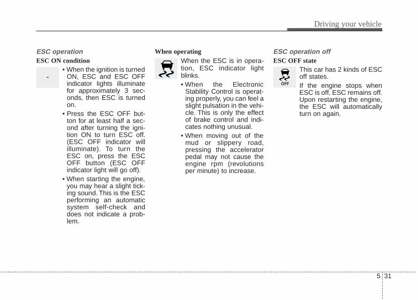
5 31
Driving your vehicle
ESC operationESC ON condition
• When the ignition is turnedON, ESC and ESC OFFindicator lights illuminatefor approximately 3 sec-onds, then ESC is turnedon.
• Press the ESC OFF but-ton for at least half a sec-ond after turning the igni-tion ON to turn ESC off.(ESC OFF indicator willilluminate). To turn theESC on, press the ESCOFF button (ESC OFFindicator light will go off).
• When starting the engine,you may hear a slight tick-ing sound. This is the ESCperforming an automaticsystem self-check anddoes not indicate a prob-lem.
When operatingWhen the ESC is in opera-tion, ESC indicator lightblinks.• When the Electronic
Stability Control is operat-ing properly, you can feel aslight pulsation in the vehi-cle. This is only the effectof brake control and indi-cates nothing unusual.
• When moving out of themud or slippery road,pressing the acceleratorpedal may not cause theengine rpm (revolutionsper minute) to increase.
ESC operation offESC OFF state
This car has 2 kinds of ESCoff states.If the engine stops whenESC is off, ESC remains off.Upon restarting the engine,the ESC will automaticallyturn on again.
-
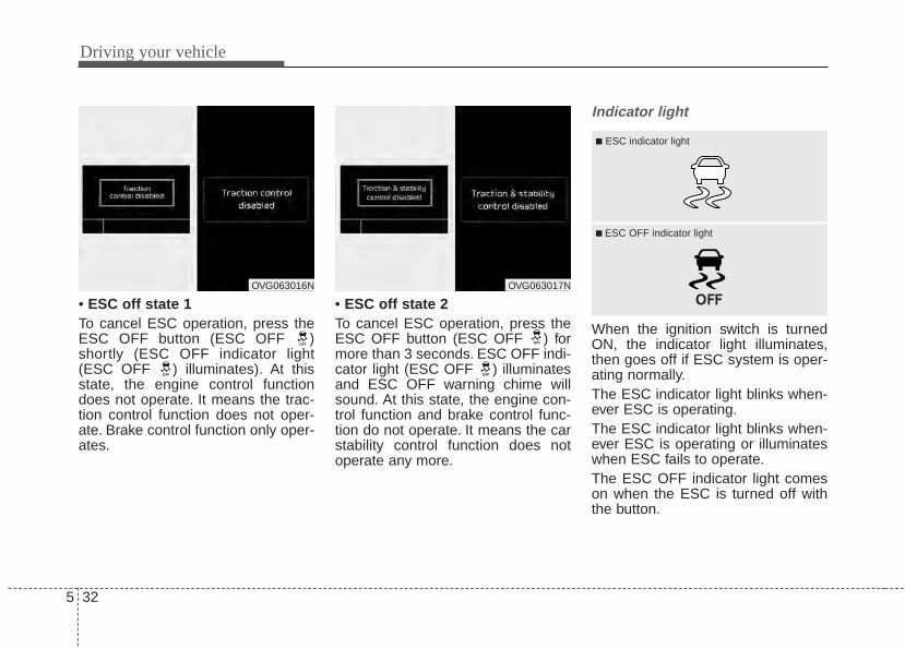
Driving your vehicle
325
• ESC off state 1To cancel ESC operation, press theESC OFF button (ESC OFF )shortly (ESC OFF indicator light(ESC OFF ) illuminates). At thisstate, the engine control functiondoes not operate. It means the trac-tion control function does not oper-ate. Brake control function only oper-ates.
• ESC off state 2To cancel ESC operation, press theESC OFF button (ESC OFF ) formore than 3 seconds. ESC OFF indi-cator light (ESC OFF ) illuminatesand ESC OFF warning chime willsound. At this state, the engine con-trol function and brake control func-tion do not operate. It means the carstability control function does notoperate any more.
Indicator light
When the ignition switch is turnedON, the indicator light illuminates,then goes off if ESC system is oper-ating normally.The ESC indicator light blinks when-ever ESC is operating.The ESC indicator light blinks when-ever ESC is operating or illuminateswhen ESC fails to operate.The ESC OFF indicator light comeson when the ESC is turned off withthe button.
■ ESC indicator light
■ ESC OFF indicator light
OVG063017NOVG063016N
5 33
Driving your vehicle
Driving with varying tire or wheelsizes may cause the ESC system tomalfunction. When replacing tires,make sure they are the same size asyour original tires.
ESC OFF usageWhen driving• It’s a good idea to keep the ESC
turned on for daily driving whenev-er possible.
• To turn ESC off while driving, pressthe ESC OFF button while drivingon a flat road surface.
Never press the ESC OFF buttonwhile ESC is operating (ESC indica-tor light blinks).If ESC is turned off while ESC isoperating, the vehicle may slip out ofcontrol.
Hill-start assist control (HAC)Hill start Assist Control is a comfortfunction. The main intent is to pre-vent the vehicle from rolling back-wards while driving uphill on aninclined surface. HAC holds the brak-ing pressure builtup by driver duringstopping procedure for 2 secondsafter releasing brake pedal.During the pressure-hold period, thedriver has enough time to press theaccelerator pedal to drive off.The braking pressure is reduced assoon as the system detects the dri-ver’s intention to drive off.
WARNING - OperatingESC
Never press the ESC OFF but-ton while ESC is operating.If the ESC is turned off whileESC is operating, the vehiclemay go out of control.
WARNING - ActivatingHAC
Drivers should pay close atten-tion when activating the HAC.The vehicle may roll backwardcausing an accident due toinsufficient brake hold pres-sure.
WARNING - Electronicstability control
Drive carefully even thoughyour vehicle has ElectronicStability Control. It can onlyassist you in maintaining con-trol under certain circum-stances.
Driving your vehicle
345
• The HAC does not operate whenthe transaxle shift lever is in the P(Park) or N (Neutral) position.
• The HAC activates even thoughthe ESC is off but it does not acti-vate when the ESC has malfunc-tioned.
Vehicle stability management(VSM)This system provides furtherenhancements to vehicle stabilityand steering responses when a vehi-cle is driving on a slippery road or avehicle detected changes in coeffi-cient of friction between right wheelsand left wheels when braking.
VSM operationWhen the VSM is in operation, ESCindicator light ( ) blinks.When the vehicle stability manage-ment is operating properly, you canfeel a slight pulsation in the vehicle.This is only the effect of brake controland indicates nothing unusual.
The VSM does not operate when:• Driving on bank road such as gra-
dient or incline• Driving rearward• ESC OFF indicator light ( )
remains on the instrument cluster• ESC indicator light remains on the
instrument cluster
VSM operation offIf you press the ESC OFF button toturn off the ESC, the VSM will alsocancel and the ESC OFF indicatorlight ( ) illuminates.To turn on the VSM, press the buttonagain. The ESC OFF indicator lightgoes out.
Malfunction indicatorThe VSM can be deactivated even ifyou don’t cancel the VSM operationby pressing the ESC OFF button. Itindicates that a malfunction hasbeen detected somewhere in theElectric Power Steering system orVSM system. If the ESC indicatorlight ( ) or ESC warning lightremains on, take your vehicle to anauthorized Kia dealer and have thesystem checked.• The VSM is designed to function
above approximately 9 mph (15km/h) on curves.
5 35
Driving your vehicle
• The VSM is designed to functionabove approximately 18 mph (30km/h) when a vehicle is braking ona split-mu road. The split-mu roadis made of surfaces which have dif-ferent friction forces.
• The Vehicle Stability Managementsystem is not a substitute for safedriving practices but a supplemen-tary function only. It is the respon-sibility of the driver to always checkthe speed and the distance to thevehicle ahead. Always hold thesteering wheel firmly while driving.
• Your vehicle is designed to activateaccording to the driver’s intention,even with installed VSM. Alwaysfollow all the normal precautionsfor driving at safe speeds for theconditions – including driving ininclement weather and on a slip-pery road.
Good braking practices• Check to be sure the parking brake
is not engaged and that the park-ing brake indicator light is outbefore driving away.
• Driving through water may get thebrakes wet. They can also get wetwhen the vehicle is washed. Wetbrakes can be dangerous! Yourvehicle will not stop as quickly if thebrakes are wet. Wet brakes maycause the vehicle to pull to oneside.To dry the brakes, apply the brakeslightly until the braking actionreturns to normal, taking care tokeep the vehicle under control atall times. If the braking action doesnot return to normal, stop as soonas it is safe to do so and call anauthorized Kia dealer for assis-tance.
• Don't coast down hills with thevehicle out of gear.This is extreme-ly hazardous. Keep the vehicle ingear at all times, use the brakes toslow down, then shift to a lowergear so that engine braking willhelp you maintain a safe speed.
WARNING - Tire/Wheelsize
When replacing tires andwheels, make sure they are thesame size as the original tiresand wheels installed. Drivingwith varying tire or wheel sizesmay diminish any supplementalsafety benefits of the VSM sys-tem.
Driving your vehicle
365
• Don't "ride" the brake pedal.Resting your foot on the brakepedal while driving can be danger-ous because the brakes mightoverheat and lose their effective-ness. It also increases the wear ofthe brake components.
• If a tire goes flat while you are driv-ing, apply the brakes gently andkeep the vehicle pointed straightahead while you slow down. Whenyou are moving slowly enough for itto be safe to do so, pull off the roadand stop in a safe place.
• If your vehicle is equipped with anautomatic transaxle, don't let yourvehicle creep forward. To avoidcreeping forward, keep your footfirmly on the brake pedal when thevehicle is stopped.
• Be cautious when parking on a hill.Firmly engage the parking brakeand place the shift lever in P (auto-matic transaxle) or in first orreverse gear (manual transaxle). Ifyour vehicle is facing downhill, turnthe front wheels into the curb tohelp keep the vehicle from rolling. Ifyour vehicle is facing uphill, turnthe front wheels away from thecurb to help keep the vehicle fromrolling. If there is no curb or if it isrequired by other conditions tokeep the vehicle from rolling, blockthe wheels.
• Under some conditions your park-ing brake can freeze in theengaged position. This is most like-ly to happen when there is anaccumulation of snow or icearound or near the rear brakes or ifthe brakes are wet. If there is a riskthat the parking brake may freeze,apply it only temporarily while youput the shift lever in P (automatictransaxle) or in first or reverse gear(manual transaxle) and block therear wheels so the vehicle cannotroll. Then release the parkingbrake.
• Do not hold the vehicle on theupgrade with the acceleratorpedal.This can cause the transaxleto overheat. Always use the brakepedal or parking brake.
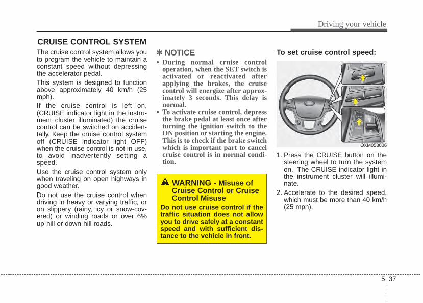
5 37
Driving your vehicle
The cruise control system allows youto program the vehicle to maintain aconstant speed without depressingthe accelerator pedal.This system is designed to functionabove approximately 40 km/h (25mph).If the cruise control is left on,(CRUISE indicator light in the instru-ment cluster illuminated) the cruisecontrol can be switched on acciden-tally. Keep the cruise control systemoff (CRUISE indicator light OFF)when the cruise control is not in use,to avoid inadvertently setting aspeed.Use the cruise control system onlywhen traveling on open highways ingood weather.Do not use the cruise control whendriving in heavy or varying traffic, oron slippery (rainy, icy or snow-cov-ered) or winding roads or over 6%up-hill or down-hill roads.
✽✽ NOTICE• During normal cruise control
operation, when the SET switch isactivated or reactivated afterapplying the brakes, the cruisecontrol will energize after approx-imately 3 seconds. This delay isnormal.
• To activate cruise control, depressthe brake pedal at least once afterturning the ignition switch to theON position or starting the engine.This is to check if the brake switchwhich is important part to cancelcruise control is in normal condi-tion.
To set cruise control speed:
1. Press the CRUISE button on thesteering wheel to turn the systemon. The CRUISE indicator light inthe instrument cluster will illumi-nate.
2. Accelerate to the desired speed,which must be more than 40 km/h(25 mph).
CRUISE CONTROL SYSTEM
WARNING - Misuse ofCruise Control or CruiseControl Misuse
Do not use cruise control if thetraffic situation does not allowyou to drive safely at a constantspeed and with sufficient dis-tance to the vehicle in front.
OXM053006
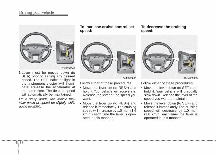
Driving your vehicle
385
3.Lever must be moved down (toSET-) prior to setting any desiredspeed. The SET indicator light inthe instrument cluster will illumi-nate. Release the accelerator atthe same time. The desired speedwill automatically be maintained.
On a steep grade, the vehicle mayslow down or speed up slightly whilegoing downhill.
To increase cruise control setspeed:
Follow either of these procedures:• Move the lever up (to RES+) and
hold it. Your vehicle will accelerate.Release the lever at the speed youwant.
• Move the lever up (to RES+) andrelease it immediately. The cruisingspeed will increase by 1.0 mph (1.6km/h ) each time the lever is oper-ated in this manner.
To decrease the cruisingspeed:
Follow either of these procedures:• Move the lever down (to SET-) and
hold it. Your vehicle will graduallyslow down. Release the lever at thespeed you want to maintain.
• Move the lever down (to SET-) andrelease it immediately. The cruisingspeed will decrease by 1.0 mph(1.6 km/h) each time the lever isoperated in this manner.
OXM053008
OXM053009 OXM053008
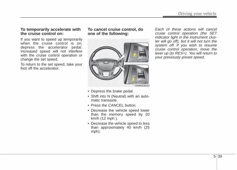
5 39
Driving your vehicle
To temporarily accelerate withthe cruise control on:If you want to speed up temporarilywhen the cruise control is on,depress the accelerator pedal.Increased speed will not interferewith the cruise control operation orchange the set speed.To return to the set speed, take yourfoot off the accelerator.
To cancel cruise control, doone of the following:
• Depress the brake pedal.• Shift into N (Neutral) with an auto-
matic transaxle.• Press the CANCEL button.• Decrease the vehicle speed lower
than the memory speed by 20km/h (12 mph ).
• Decrease the vehicle speed to lessthan approximately 40 km/h (25mph).
Each of these actions will cancelcruise control operation (the SETindicator light in the instrument clus-ter will go off), but it will not turn thesystem off. If you wish to resumecruise control operation, move thelever up (to RES+). You will return toyour previously preset speed.
OXM053010
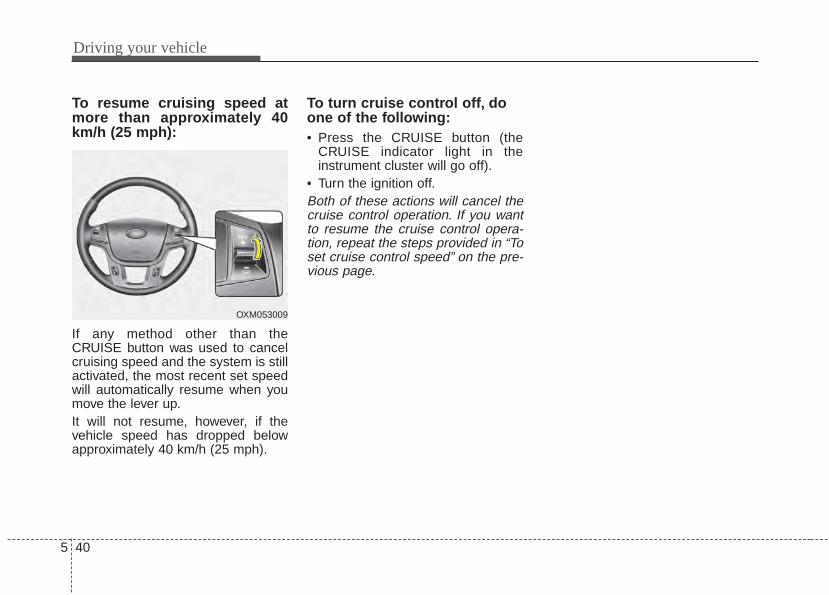
Driving your vehicle
405
To resume cruising speed atmore than approximately 40km/h (25 mph):
If any method other than theCRUISE button was used to cancelcruising speed and the system is stillactivated, the most recent set speedwill automatically resume when youmove the lever up.It will not resume, however, if thevehicle speed has dropped belowapproximately 40 km/h (25 mph).
To turn cruise control off, doone of the following:• Press the CRUISE button (the
CRUISE indicator light in theinstrument cluster will go off).
• Turn the ignition off.Both of these actions will cancel thecruise control operation. If you wantto resume the cruise control opera-tion, repeat the steps provided in “Toset cruise control speed” on the pre-vious page.
OXM053009
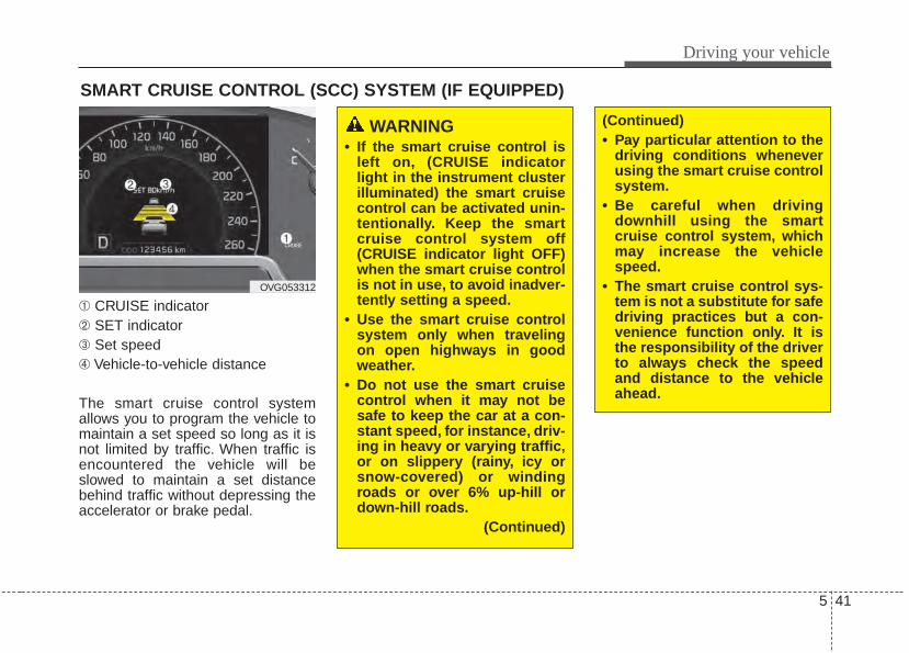
5 41
Driving your vehicle
➀ CRUISE indicator➁ SET indicator➂ Set speed➃ Vehicle-to-vehicle distance
The smart cruise control systemallows you to program the vehicle tomaintain a set speed so long as it isnot limited by traffic. When traffic isencountered the vehicle will beslowed to maintain a set distancebehind traffic without depressing theaccelerator or brake pedal.
SMART CRUISE CONTROL (SCC) SYSTEM (IF EQUIPPED)
OVG053312
WARNING • If the smart cruise control is
left on, (CRUISE indicatorlight in the instrument clusterilluminated) the smart cruisecontrol can be activated unin-tentionally. Keep the smartcruise control system off(CRUISE indicator light OFF)when the smart cruise controlis not in use, to avoid inadver-tently setting a speed.
• Use the smart cruise controlsystem only when travelingon open highways in goodweather.
• Do not use the smart cruisecontrol when it may not besafe to keep the car at a con-stant speed, for instance, driv-ing in heavy or varying traffic,or on slippery (rainy, icy orsnow-covered) or windingroads or over 6% up-hill ordown-hill roads.
(Continued)
(Continued)• Pay particular attention to the
driving conditions wheneverusing the smart cruise controlsystem.
• Be careful when drivingdownhill using the smartcruise control system, whichmay increase the vehiclespeed.
• The smart cruise control sys-tem is not a substitute for safedriving practices but a con-venience function only. It isthe responsibility of the driverto always check the speedand distance to the vehicleahead.
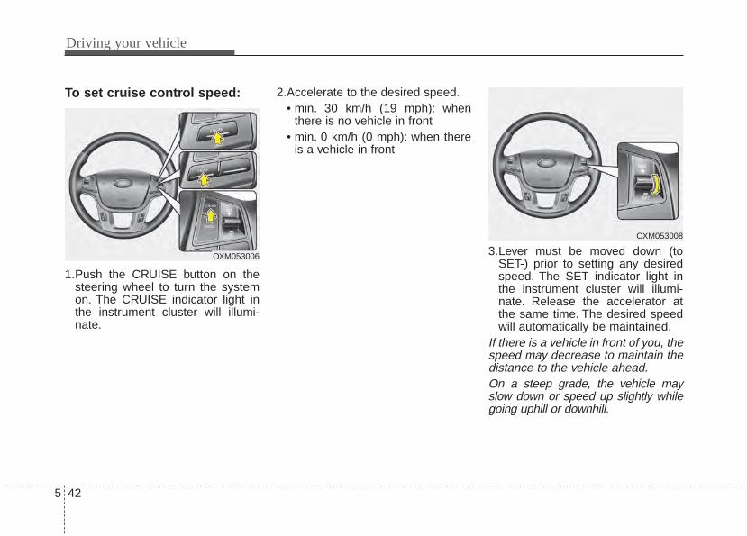
Driving your vehicle
425
To set cruise control speed:
1.Push the CRUISE button on thesteering wheel to turn the systemon. The CRUISE indicator light inthe instrument cluster will illumi-nate.
2.Accelerate to the desired speed.• min. 30 km/h (19 mph): when
there is no vehicle in front• min. 0 km/h (0 mph): when there
is a vehicle in front
3.Lever must be moved down (toSET-) prior to setting any desiredspeed. The SET indicator light inthe instrument cluster will illumi-nate. Release the accelerator atthe same time. The desired speedwill automatically be maintained.
If there is a vehicle in front of you, thespeed may decrease to maintain thedistance to the vehicle ahead.On a steep grade, the vehicle mayslow down or speed up slightly whilegoing uphill or downhill.
OXM053006
OXM053008
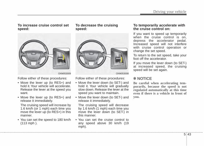
5 43
Driving your vehicle
To increase cruise control setspeed:
Follow either of these procedures:• Move the lever up (to RES+) and
hold it. Your vehicle will accelerate.Release the lever at the speed youwant.
• Move the lever up (to RES+) andrelease it immediately.The cruising speed will increase by1.6 km/h (or 1 mph) each time youmove the lever up (to RES+) in thismanner.
• You can set the speed to 180 km/h(113 mph ).
To decrease the cruisingspeed:
Follow either of these procedures:• Move the lever down (to SET-) and
hold it. Your vehicle will graduallyslow down. Release the lever at thespeed you want to maintain.
• Move the lever down (to SET-) andrelease it immediately.The cruising speed will decreaseby 1.6 km/h (1 mph) each time youmove the lever down (to SET-) inthis manner.
• You can set the cruise control toany speed above 30 km/h (19mph).
To temporarily accelerate withthe cruise control on:If you want to speed up temporarilywhen the cruise control is on,depress the accelerator pedal.Increased speed will not interferewith cruise control operation orchange the set speed.To return to the set speed, take yourfoot off the accelerator.If you move the lever down (to SET-)at increased speed, the cruisingspeed will be set again.
✽✽ NOTICEBe careful when accelerating tem-porarily, because the speed is notregulated automatically at this timeeven if there is a vehicle in front ofyou.
OXM053009 OXM053008

Driving your vehicle
445
Smart Cruise control will be tem-porarily canceled when:
Cancelled manually• When the vehicle is stopped.
- Press the CANCEL switch locat-ed on the steering wheel whiledepress the brake pedal
• When the vehicle is moving- Depress the brake pedal or press
the CANCEL switch located onthe steering wheel.
The smart cruise control turns offtemporarily when the indicator on theLCD display turns off.The CRUISE indicator is illuminatedcontinuously.
Cancelled automatically• The driver's door is opened.• The shift lever is shifted to N
(Neutral), R (Reverse) or D (Drive).• The EPB (electronic parking brake)
is applied.• The vehicle speed is over 180km/h
(113mph)• The vehicle stops on a steep
incline.• The ESC or ABS is operating.• The ESC is turned off.• The sensor or the cover is dirty or
blocked with foreign matter.• When the vehicle is stopped for
over 5 minutes.• The vehicle stops and go repeat-
edly for a long period of time.• The driver starts driving by
depressing the accelerator pedalor move the lever (to RES+ or SET-), if a vehicle stops far away aheadof the your vehicle.
• The accelerator pedal is continu-ously depressed for more than 1minute.
Each of these actions will cancelthe smart cruise control operation.(the SET indicator, set speed andvehicle to vehicle distance on theLCD display will go off.) In a condition the smart cruise con-trol is cancelled automatically, thesmart cruise control will notresume even though the RES+ orSET- lever is moved. Also, the EPB(electronic parking brake) will beapplied when the vehicle isstopped.
OXM053010
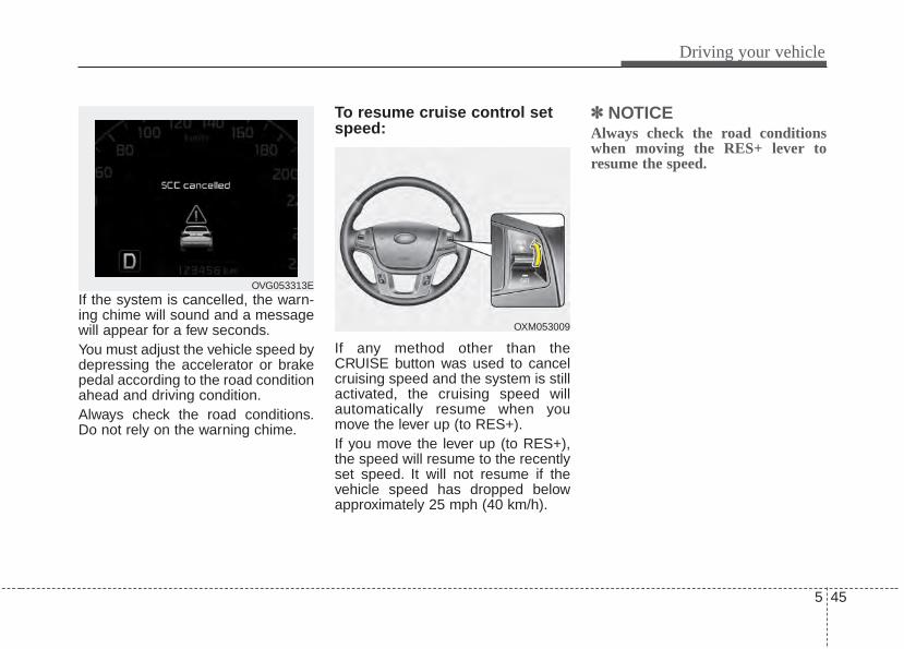
5 45
Driving your vehicle
If the system is cancelled, the warn-ing chime will sound and a messagewill appear for a few seconds.You must adjust the vehicle speed bydepressing the accelerator or brakepedal according to the road conditionahead and driving condition.Always check the road conditions.Do not rely on the warning chime.
To resume cruise control setspeed:
If any method other than theCRUISE button was used to cancelcruising speed and the system is stillactivated, the cruising speed willautomatically resume when youmove the lever up (to RES+).If you move the lever up (to RES+),the speed will resume to the recentlyset speed. It will not resume if thevehicle speed has dropped belowapproximately 25 mph (40 km/h).
✽✽ NOTICEAlways check the road conditionswhen moving the RES+ lever toresume the speed.
OVG053313E
OXM053009
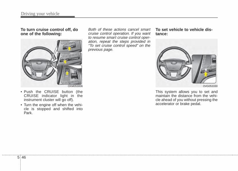
Driving your vehicle
465
To turn cruise control off, doone of the following:
• Push the CRUISE button (theCRUISE indicator light in theinstrument cluster will go off).
• Turn the engine off when the vehi-cle is stopped and shifted intoPark.
Both of these actions cancel smartcruise control operation. If you wantto resume smart cruise control oper-ation, repeat the steps provided in“To set cruise control speed” on theprevious page.
To set vehicle to vehicle dis-tance:
This system allows you to set andmaintain the distance from the vehi-cle ahead of you without pressing theaccelerator or brake pedal.
OXM053006 OVG053330
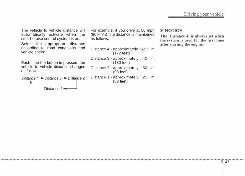
5 47
Driving your vehicle
The vehicle to vehicle distance willautomatically activate when thesmart cruise control system is on.Select the appropriate distanceaccording to road conditions andvehicle speed.
Each time the button is pressed, thevehicle to vehicle distance changesas follows;
For example, if you drive at 56 mph(90 km/h), the distance is maintainedas follows;
Distance 4 - approximately 52.5 m(172 feet)
Distance 3 - approximately 40 m(130 feet)
Distance 2 - approximately 30 m(98 feet)
Distance 1 - approximately 25 m(82 feet)
✽✽ NOTICEThe 'Distance 4' is always set whenthe system is used for the first timeafter starting the engine.
Distance 4 Distance 3 Distance 2
Distance 1
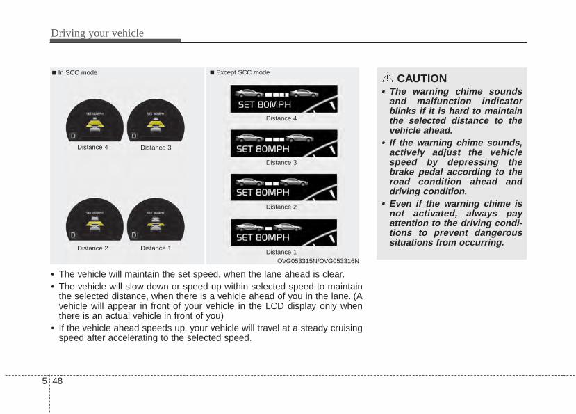
Driving your vehicle
485
■ In SCC mode ■ Except SCC mode
• The vehicle will maintain the set speed, when the lane ahead is clear.• The vehicle will slow down or speed up within selected speed to maintain
the selected distance, when there is a vehicle ahead of you in the lane. (Avehicle will appear in front of your vehicle in the LCD display only whenthere is an actual vehicle in front of you)
• If the vehicle ahead speeds up, your vehicle will travel at a steady cruisingspeed after accelerating to the selected speed.
CAUTION• The warning chime sounds
and malfunction indicatorblinks if it is hard to maintainthe selected distance to thevehicle ahead.
• If the warning chime sounds,actively adjust the vehiclespeed by depressing thebrake pedal according to theroad condition ahead anddriving condition.
• Even if the warning chime isnot activated, always payattention to the driving condi-tions to prevent dangeroussituations from occurring.
Distance 4 Distance 3
Distance 2 Distance 1
Distance 4
Distance 3
Distance 2
Distance 1OVG053315N/OVG053316N
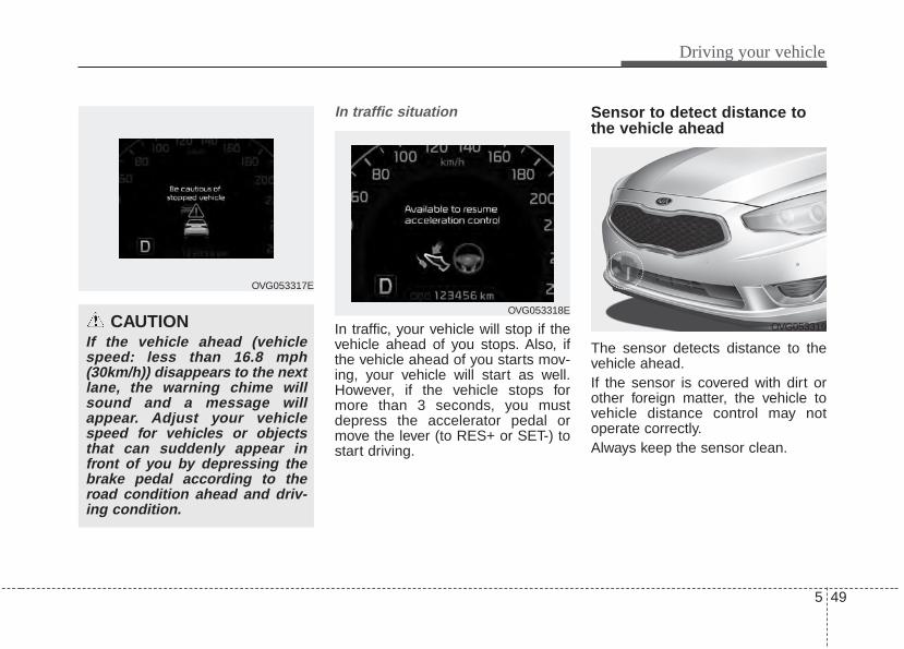
5 49
Driving your vehicle
In traffic situation
In traffic, your vehicle will stop if thevehicle ahead of you stops. Also, ifthe vehicle ahead of you starts mov-ing, your vehicle will start as well.However, if the vehicle stops formore than 3 seconds, you mustdepress the accelerator pedal ormove the lever (to RES+ or SET-) tostart driving.
Sensor to detect distance tothe vehicle ahead
The sensor detects distance to thevehicle ahead.If the sensor is covered with dirt orother foreign matter, the vehicle tovehicle distance control may notoperate correctly.Always keep the sensor clean.
CAUTIONIf the vehicle ahead (vehiclespeed: less than 16.8 mph(30km/h)) disappears to the nextlane, the warning chime willsound and a message willappear. Adjust your vehiclespeed for vehicles or objectsthat can suddenly appear infront of you by depressing thebrake pedal according to theroad condition ahead and driv-ing condition.
OVG053317E
OVG053318E
OVG053319
Driving your vehicle
505
Sensor malfunction indicator If the sensor or cover isdirty or obscured withforeign matter such assnow, the indicator willilluminate. Clean thesensor by using a softcloth.
SCC (Smart cruise control) mal-function indicator
The warning light illumi-nates when the vehicleto vehicle distance con-trol system is not func-tioning normally.Take your vehicle to anauthorized Kia dealerand have the systemchecked.
CAUTION• Do not install accessories
around the sensor and do notreplace the bumper by your-self. It may interfere with thesensor performance.
• Always keep the sensor andbumper clean.
• To prevent sensor cover dam-age from occurring, wash thecar with a soft cloth.
• Do not damage the sensor orsensor area by a strongimpact. If the sensor movesslightly off position, the smartcruise control system will notoperate correctly.If this occurs, have your vehi-cle checked by an authorizedKia dealer as soon as possi-ble.
• Use only a genuine Kia sensorcover for your vehicle.
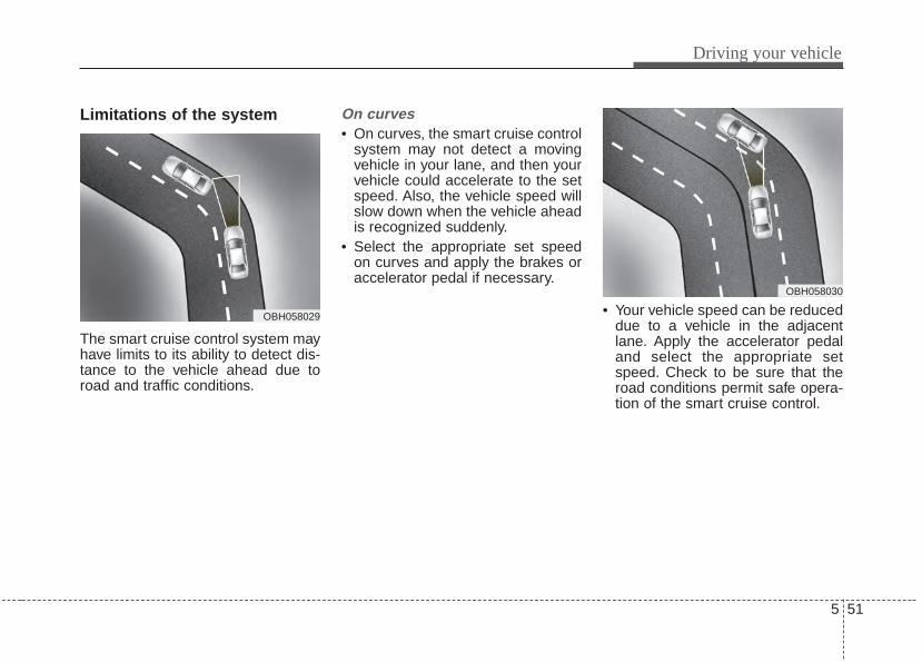
5 51
Driving your vehicle
Limitations of the system
The smart cruise control system mayhave limits to its ability to detect dis-tance to the vehicle ahead due toroad and traffic conditions.
On curves• On curves, the smart cruise control
system may not detect a movingvehicle in your lane, and then yourvehicle could accelerate to the setspeed. Also, the vehicle speed willslow down when the vehicle aheadis recognized suddenly.
• Select the appropriate set speedon curves and apply the brakes oraccelerator pedal if necessary.
• Your vehicle speed can be reduceddue to a vehicle in the adjacentlane. Apply the accelerator pedaland select the appropriate setspeed. Check to be sure that theroad conditions permit safe opera-tion of the smart cruise control.
OBH058030
OBH058029
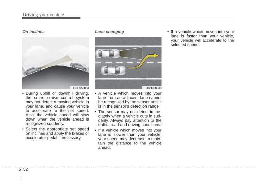
Driving your vehicle
525
On inclines
• During uphill or downhill driving,the smart cruise control systemmay not detect a moving vehicle inyour lane, and cause your vehicleto accelerate to the set speed.Also, the vehicle speed will slowdown when the vehicle ahead isrecognized suddenly.
• Select the appropriate set speedon inclines and apply the brakes oraccelerator pedal if necessary.
Lane changing
• A vehicle which moves into yourlane from an adjacent lane cannotbe recognized by the sensor until itis in the sensor's detection range.
• The sensor may not detect imme-diately when a vehicle cuts in sud-denly. Always pay attention to thetraffic, road and driving conditions.
• If a vehicle which moves into yourlane is slower than your vehicle,your speed may decrease to main-tain the distance to the vehicleahead.
• If a vehicle which moves into yourlane is faster than your vehicle,your vehicle will accelerate to theselected speed.
OBH058045OBH058053
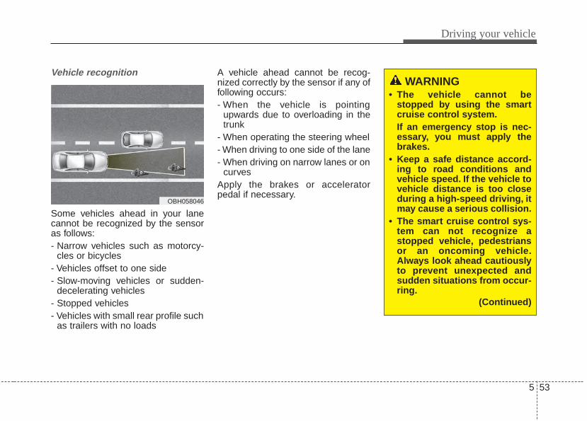
5 53
Driving your vehicle
Vehicle recognition
Some vehicles ahead in your lanecannot be recognized by the sensoras follows:- Narrow vehicles such as motorcy-
cles or bicycles- Vehicles offset to one side- Slow-moving vehicles or sudden-
decelerating vehicles - Stopped vehicles- Vehicles with small rear profile such
as trailers with no loads
A vehicle ahead cannot be recog-nized correctly by the sensor if any offollowing occurs:- When the vehicle is pointing
upwards due to overloading in thetrunk
- When operating the steering wheel- When driving to one side of the lane- When driving on narrow lanes or on
curvesApply the brakes or acceleratorpedal if necessary.
OBH058046
WARNING • The vehicle cannot be
stopped by using the smartcruise control system.If an emergency stop is nec-essary, you must apply thebrakes.
• Keep a safe distance accord-ing to road conditions andvehicle speed. If the vehicle tovehicle distance is too closeduring a high-speed driving, itmay cause a serious collision.
• The smart cruise control sys-tem can not recognize astopped vehicle, pedestriansor an oncoming vehicle.Always look ahead cautiouslyto prevent unexpected andsudden situations from occur-ring.
(Continued)
Driving your vehicle
545
(Continued)• Vehicles moving in front of
you with a frequent lanechange may cause a delay inthe system's reaction or maycause the system to react to avehicle actually in an adjacentlane. Always look ahead cau-tiously to prevent unexpectedand sudden situations fromoccurring.
• The smart cruise control sys-tem is not a substitute for safedriving practices but a con-venience function only. It isthe responsibility of the driverto always check the speedand the distance to the vehi-cle ahead.
• Always be aware of the select-ed speed and vehicle to vehi-cle distance.
• Always maintain sufficientbraking distance and deceler-ate your vehicle by applyingthe brakes if necessary.
(Continued)
(Continued)• As the smart cruise control
system may not recognizecomplex driving situations,always pay attention to driv-ing conditions and controlyour vehicle speed.
• For safe operation, carefullyread and follow the instruc-tions in this manual beforeuse.
CAUTIONThe smart cruise control systemmay not operate temporarilydue to electrical interference.
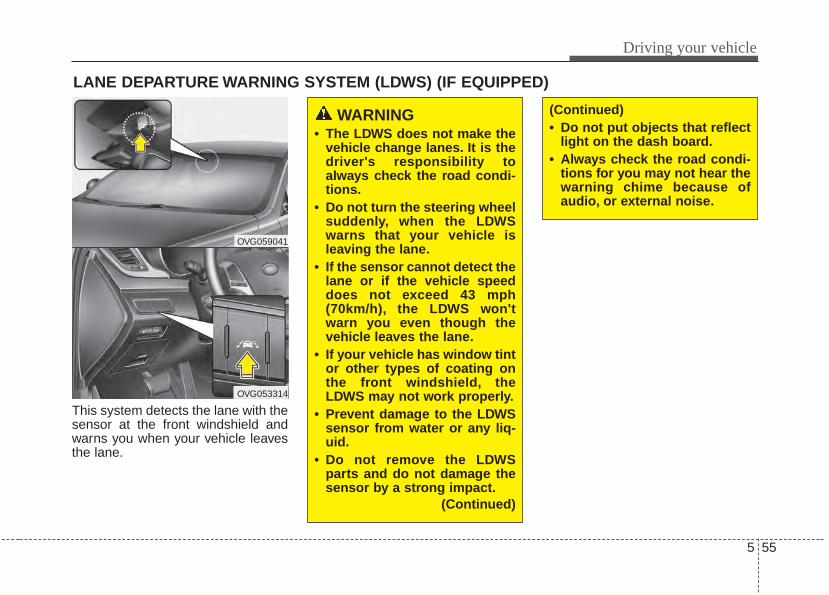
5 55
Driving your vehicle
This system detects the lane with thesensor at the front windshield andwarns you when your vehicle leavesthe lane.
LANE DEPARTURE WARNING SYSTEM (LDWS) (IF EQUIPPED)
OVG059041
OVG053314
WARNING • The LDWS does not make the
vehicle change lanes. It is thedriver's responsibility toalways check the road condi-tions.
• Do not turn the steering wheelsuddenly, when the LDWSwarns that your vehicle isleaving the lane.
• If the sensor cannot detect thelane or if the vehicle speeddoes not exceed 43 mph(70km/h), the LDWS won'twarn you even though thevehicle leaves the lane.
• If your vehicle has window tintor other types of coating onthe front windshield, theLDWS may not work properly.
• Prevent damage to the LDWSsensor from water or any liq-uid.
• Do not remove the LDWSparts and do not damage thesensor by a strong impact.
(Continued)
(Continued)• Do not put objects that reflect
light on the dash board.• Always check the road condi-
tions for you may not hear thewarning chime because ofaudio, or external noise.
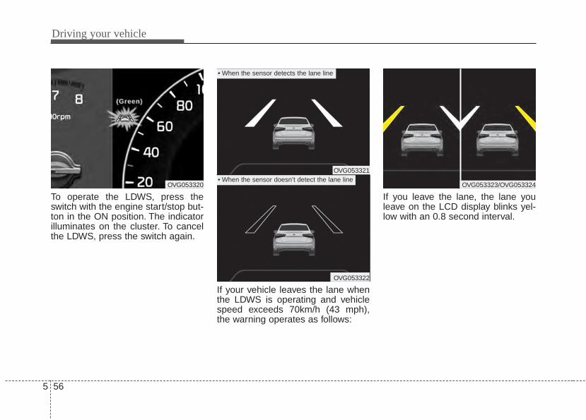
Driving your vehicle
565
To operate the LDWS, press theswitch with the engine start/stop but-ton in the ON position. The indicatorilluminates on the cluster. To cancelthe LDWS, press the switch again.
If your vehicle leaves the lane whenthe LDWS is operating and vehiclespeed exceeds 70km/h (43 mph),the warning operates as follows:
If you leave the lane, the lane youleave on the LCD display blinks yel-low with an 0.8 second interval.
OVG053320
((((GGGGrrrreeeeeeeennnn))))
OVG053321
OVG053322
• When the sensor detects the lane line
• When the sensor doesn’t detect the lane lineOVG053323/OVG053324
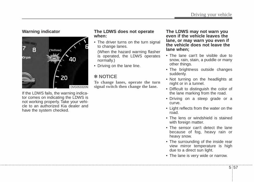
5 57
Driving your vehicle
Warning indicator
If the LDWS fails, the warning indica-tor comes on indicating the LDWS isnot working properly. Take your vehi-cle to an authorized Kia dealer andhave the system checked.
The LDWS does not operatewhen:• The driver turns on the turn signal
to change lanes.(When the hazard warning flasheris operated, the LDWS operatesnormally.)
• Driving on the lane line.
✽✽ NOTICETo change lanes, operate the turnsignal switch then change the lane.
The LDWS may not warn youeven if the vehicle leaves thelane, or may warn you even ifthe vehicle does not leave thelane when;• The lane can't be visible due to
snow, rain, stain, a puddle or manyother things.
• The brightness outside changessuddenly.
• Not turning on the headlights atnight or in a tunnel.
• Difficult to distinguish the color ofthe lane marking from the road.
• Driving on a steep grade or acurve.
• Light reflects from the water on theroad.
• The lens or windshield is stainedwith foreign matter.
• The sensor can't detect the lanebecause of fog, heavy rain orheavy snow.
• The surrounding of the inside rearview mirror temperature is highdue to a direct sun light.
• The lane is very wide or narrow.
OVG053320N
(((( YYYYeeee llll lllloooowwww ))))
Driving your vehicle
585
• The lane line is damaged or indis-tinct.
• A shadow is on the lane line by amedian strip.
• There is a mark that looks like alane line.
• There is a boundary structure.• The distance from vehicle ahead is
very short or the vehicle aheaddrives hiding the lane line.
• The vehicle shakes heavily.• The lane number increases or
decreases or the lane lines arecrossing.
• Putting something on the dash-board.
• Driving with the sun in front of you.• Driving in areas under construc-
tion.• The lane line is more than two.
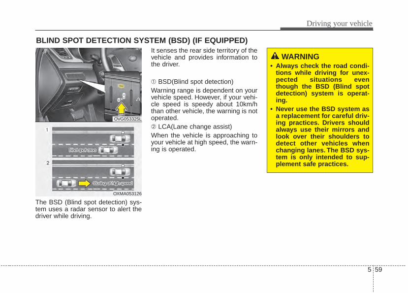
5 59
Driving your vehicle
The BSD (Blind spot detection) sys-tem uses a radar sensor to alert thedriver while driving.
It senses the rear side territory of thevehicle and provides information tothe driver.
➀ BSD(Blind spot detection)Warning range is dependent on yourvehicle speed. However, if your vehi-cle speed is speedy about 10km/hthan other vehicle, the warning is notoperated.➁ LCA(Lane change assist)When the vehicle is approaching toyour vehicle at high speed, the warn-ing is operated.
BLIND SPOT DETECTION SYSTEM (BSD) (IF EQUIPPED)
WARNING • Always check the road condi-
tions while driving for unex-pected situations eventhough the BSD (Blind spotdetection) system is operat-ing.
• Never use the BSD system asa replacement for careful driv-ing practices. Drivers shouldalways use their mirrors andlook over their shoulders todetect other vehicles whenchanging lanes. The BSD sys-tem is only intended to sup-plement safe practices.
OVG053325L
OXMA053126
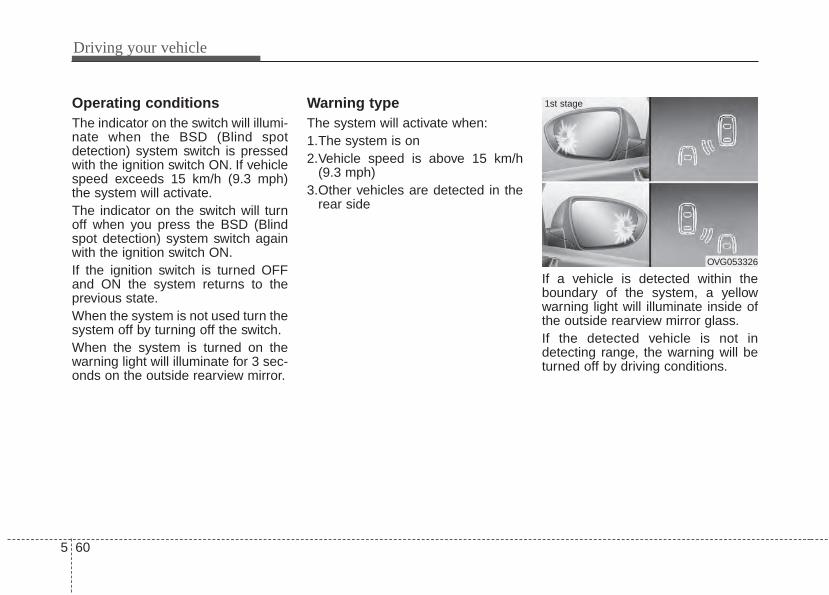
Driving your vehicle
605
Operating conditionsThe indicator on the switch will illumi-nate when the BSD (Blind spotdetection) system switch is pressedwith the ignition switch ON. If vehiclespeed exceeds 15 km/h (9.3 mph)the system will activate.The indicator on the switch will turnoff when you press the BSD (Blindspot detection) system switch againwith the ignition switch ON.If the ignition switch is turned OFFand ON the system returns to theprevious state.When the system is not used turn thesystem off by turning off the switch.When the system is turned on thewarning light will illuminate for 3 sec-onds on the outside rearview mirror.
Warning typeThe system will activate when:1.The system is on 2.Vehicle speed is above 15 km/h
(9.3 mph)3.Other vehicles are detected in the
rear side
If a vehicle is detected within theboundary of the system, a yellowwarning light will illuminate inside ofthe outside rearview mirror glass.If the detected vehicle is not indetecting range, the warning will beturned off by driving conditions.
OVG053326
1st stage
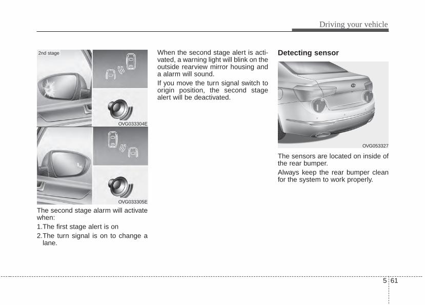
5 61
Driving your vehicle
The second stage alarm will activatewhen:1.The first stage alert is on2.The turn signal is on to change a
lane.
When the second stage alert is acti-vated, a warning light will blink on theoutside rearview mirror housing anda alarm will sound.If you move the turn signal switch toorigin position, the second stagealert will be deactivated.
Detecting sensor
The sensors are located on inside ofthe rear bumper.Always keep the rear bumper cleanfor the system to work properly.
OVG053327
OVG033304E
OVG033305E
2nd stage
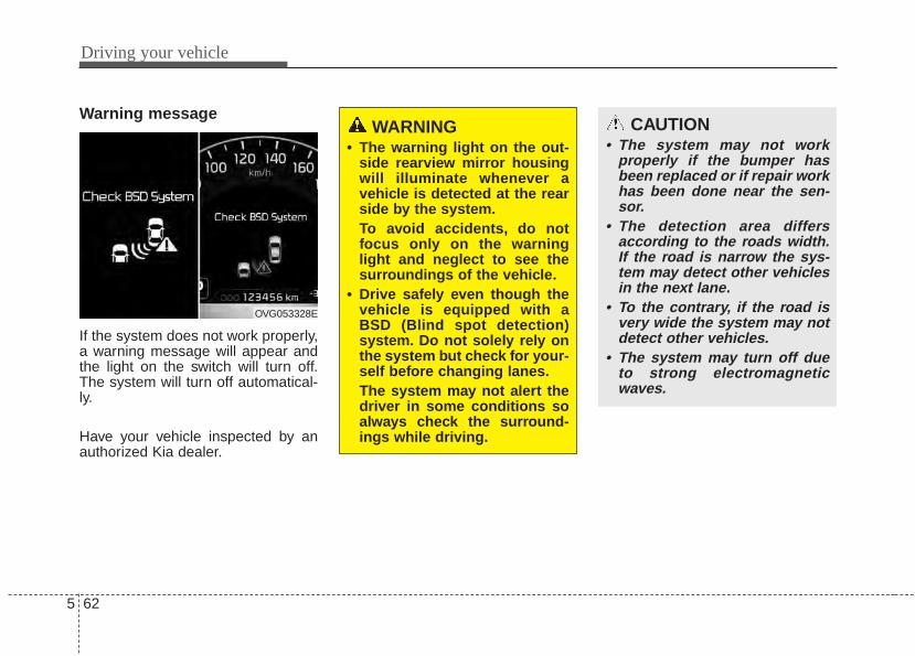
Driving your vehicle
625
Warning message
If the system does not work properly,a warning message will appear andthe light on the switch will turn off.The system will turn off automatical-ly.
Have your vehicle inspected by anauthorized Kia dealer.
OVG053328E
WARNING • The warning light on the out-
side rearview mirror housingwill illuminate whenever avehicle is detected at the rearside by the system.To avoid accidents, do notfocus only on the warninglight and neglect to see thesurroundings of the vehicle.
• Drive safely even though thevehicle is equipped with aBSD (Blind spot detection)system. Do not solely rely onthe system but check for your-self before changing lanes.The system may not alert thedriver in some conditions soalways check the surround-ings while driving.
CAUTION• The system may not work
properly if the bumper hasbeen replaced or if repair workhas been done near the sen-sor.
• The detection area differsaccording to the roads width.If the road is narrow the sys-tem may detect other vehiclesin the next lane.
• To the contrary, if the road isvery wide the system may notdetect other vehicles.
• The system may turn off dueto strong electromagneticwaves.
5 63
Driving your vehicle
Non-operating conditionDriver's AttentionThe driver must be cautious in thefollowing situations in which the sys-tem may not assist the driver andmay not function properly.
- Curved roads, tollgates, etc.- The surrounding of the sensor is
covered by rain, snow, mud, etc- The rear bumper near the sensor is
covered or hidden with a foreignmatter such as a sticker, bumperguard, bicycle stand etc.
- The rear bumper is damaged or thesensor is out of place.
- The height of the vehicle ischanged or altered such as whenthe trunk is loaded with heavyobjects, or has abnormal tire pres-sure etc.
- Due to bad weather such as heavyrain or snow.
- A fixed object is near such as aguardrail, tunnel, animals etc.
- A lot of amount of metal sub-stances are near the vehicles suchas a construction area.
- A big vehicle is near such as a busor truck.
- A motorcycle or bicycle is near.- A flat trailer like vehicle is near.- If the vehicle has started at the
same time as the vehicle next to itand has accelerated.
- When the other vehicle passes byvery fast.
- When changing lanes.- When going down or up a steep
road where the height of the lane isdifferent.
- When the other vehicle drives atthe rear very nearby or drives veryclose.
- When the temperature near thebumper is high.
- When a trailer or carrier is installed.
Outside rearview mirror may notalert the driver when:- The outside rearview mirror hous-
ing is covered with foreign matter.- The window is covered with foreign
matter.- The windows are severely tinted.
Driving your vehicle
645
ECONOMICAL OPERATIONYour vehicle's fuel economy dependsmainly on your style of driving, whereyou drive and when you drive.Each of these factors affects howmany miles (kilometers) you can getfrom a gallon (liter) of fuel.To operateyour vehicle as economically as pos-sible, use the following driving sug-gestions to help save money in bothfuel and repairs:• Drive smoothly. Accelerate at a
moderate rate. Don't make "jack-rabbit" starts or full-throttle shiftsand maintain a steady cruisingspeed. Don't race between stop-lights. Try to adjust your speed tothe traffic so you don't have tochange speeds unnecessarily.Avoid heavy traffic whenever pos-sible. Always maintain a safe dis-tance from other vehicles so youcan avoid unnecessary braking.This also reduces brake wear.
• Drive at a moderate speed. Thefaster you drive, the more fuel yourvehicle uses. Driving at a moderatespeed, especially on the highway,is one of the most effective ways toreduce fuel consumption.
• Don't "ride" the brake pedal. Thiscan increase fuel consumption andalso increase wear on these com-ponents. In addition, driving withyour foot resting on the brake pedalmay cause the brakes to overheat,which reduces their effectivenessand may lead to more serious con-sequences.
• Take care of your tires. Keep theminflated to the recommended pres-sure. Incorrect inflation, either toomuch or too little, results in unnec-essary tire wear. Check the tirepressures at least once a month.
• Be sure that the wheels arealigned correctly. Improper align-ment can result from hitting curbsor driving too fast over irregularsurfaces. Poor alignment causesfaster tire wear and may also resultin other problems as well asgreater fuel consumption.
• Keep your vehicle in good condi-tion. For better fuel economy andreduced maintenance costs, main-tain your vehicle in accordancewith the maintenance schedule insection 7. If you drive your vehiclein severe conditions, more frequentmaintenance is required (see sec-tion 7 for details).
• Keep your vehicle clean. For maxi-mum service, your vehicle shouldbe kept clean and free of corrosivematerials. It is especially importantthat mud, dirt, ice, etc. not beallowed to accumulate on theunderside of the vehicle. This extraweight can result in increased fuelconsumption and also contribute tocorrosion.
• Travel lightly. Don't carry unneces-sary weight in your vehicle. Weightreduces fuel economy.
• Don't let the engine idle longerthan necessary. If you are waiting(and not in traffic), turn off yourengine and restart only whenyou're ready to go.
5 65
Driving your vehicle
• Remember, your vehicle does notrequire extended warm-up. Afterthe engine has started, allow theengine to run for 10 to 20 secondsprior to placing the vehicle in gear.In very cold weather, however, giveyour engine a slightly longer warm-up period.
• Don't "lug" or "over-rev" the engine.Lugging is driving too slowly in avery high gear resulting in enginebucking. If this happens, shift to alower gear. Over-revving is racingthe engine beyond its safe limit.This can be avoided by shifting atthe recommended speed.
• Use your air conditioning sparingly.The air conditioning system isoperated by engine power so yourfuel economy is reduced when youuse it.
• Open windows at high speeds canreduce fuel economy.
• Fuel economy is reduced by cross-winds and headwinds. To help off-set some of this loss, slow downwhen driving in these conditions.
Keeping a vehicle in good operatingcondition is important both for econ-omy and safety. Therefore, have anauthorized Kia dealer performscheduled inspections and mainte-nance.
WARNING - Engine offduringmotion
Never turn the engine off tocoast down hills or anytime thevehicle is in motion. The powersteering and power brakes willnot function properly withoutthe engine running. In addition,turning off the ignition whiledriving could engage the steer-ing wheel lock resulting in lossof vehicle steering. Keep theengine on and downshift to anappropriate gear for enginebraking effect.
Driving your vehicle
665
Hazardous driving conditions When hazardous driving conditionsare encountered such as water,snow, ice, mud, sand, or similar haz-ards, follow these suggestions:• Drive cautiously and allow extra
distance for braking.• Avoid sudden braking or steering.• When braking with non-ABS
brakes pump the brake pedal witha light up-and-down motion untilthe vehicle is stopped.
Do not pump the brake pedal on avehicle equipped with ABS.• If stalled in snow, mud, or sand,
use second gear. Accelerate slow-ly to avoid spinning the drivewheels.
• Use sand, rock salt, or other non-slip material under the drivewheels to provide traction whenstalled in ice, snow, or mud.
Rocking the vehicle If it is necessary to rock the vehicleto free it from snow, sand, or mud,first turn the steering wheel right andleft to clear the area around yourfront wheels. Then, shift back andforth between R (Reverse) and anyforward gear in vehicles equippedwith an automatic transaxle. Do notrace the engine, and spin the wheelsas little as possible. If you are stillstuck after a few tries, have the vehi-cle pulled out by a tow vehicle toavoid engine overheating and possi-ble damage to the transaxle.The ESC system should be turnedOFF prior to rocking the vehicle.
SPECIAL DRIVING CONDITIONS
WARNING - Downshifting
Do not downshift with an auto-matic transaxle while driving onslippery surfaces. The suddenchange in tire speed couldcause the tires to skid andresult in an accident. CAUTION - Vehicle
rockingProlonged rocking may causeengine overheating, transaxledamage or failure, and tire dam-age.
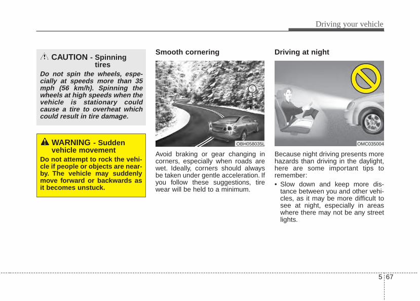
5 67
Driving your vehicle
Smooth cornering
Avoid braking or gear changing incorners, especially when roads arewet. Ideally, corners should alwaysbe taken under gentle acceleration. Ifyou follow these suggestions, tirewear will be held to a minimum.
Driving at night
Because night driving presents morehazards than driving in the daylight,here are some important tips toremember:• Slow down and keep more dis-
tance between you and other vehi-cles, as it may be more difficult tosee at night, especially in areaswhere there may not be any streetlights.
OBH058035L OMC035004WARNING - Sudden vehicle movement
Do not attempt to rock the vehi-cle if people or objects are near-by. The vehicle may suddenlymove forward or backwards asit becomes unstuck.
CAUTION - Spinningtires
Do not spin the wheels, espe-cially at speeds more than 35mph (56 km/h). Spinning thewheels at high speeds when thevehicle is stationary couldcause a tire to overheat whichcould result in tire damage.
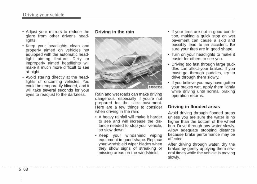
Driving your vehicle
685
• Adjust your mirrors to reduce theglare from other driver's head-lights.
• Keep your headlights clean andproperly aimed on vehicles notequipped with the automatic head-light aiming feature. Dirty orimproperly aimed headlights willmake it much more difficult to seeat night.
• Avoid staring directly at the head-lights of oncoming vehicles. Youcould be temporarily blinded, and itwill take several seconds for youreyes to readjust to the darkness.
Driving in the rain
Rain and wet roads can make drivingdangerous, especially if you’re notprepared for the slick pavement.Here are a few things to considerwhen driving in the rain:• A heavy rainfall will make it harder
to see and will increase the dis-tance needed to stop your vehicle,so slow down.
• Keep your windshield wipingequipment in good shape. Replaceyour windshield wiper blades whenthey show signs of streaking ormissing areas on the windshield.
• If your tires are not in good condi-tion, making a quick stop on wetpavement can cause a skid andpossibly lead to an accident. Besure your tires are in good shape.
• Turn on your headlights to make iteasier for others to see you.
• Driving too fast through large pud-dles can affect your brakes. If youmust go through puddles, try todrive through them slowly.
• If you believe you may have gottenyour brakes wet, apply them lightlywhile driving until normal brakingoperation returns.
Driving in flooded areas Avoid driving through flooded areasunless you are sure the water is nohigher than the bottom of the wheelhub. Drive through any water slowly.Allow adequate stopping distancebecause brake performance may beaffected.After driving through water, dry thebrakes by gently applying them sev-eral times while the vehicle is movingslowly.
1JBB3303
5 69
Driving your vehicle
Driving off-roadDrive carefully off-road because yourvehicle may be damaged by rocks orroots of trees. Become familiar withthe off-road conditions where youare going to drive before you begindriving.
Highway drivingTires Adjust the tire inflation pressures tospecification. Low tire inflation pres-sures will result in overheating andpossible failure of the tires.Avoid using worn or damaged tireswhich may result in reduced tractionor tire failure.Never exceed the maximum tireinflation pressure shown on the tires.
Fuel, engine coolant and engineoilHigh speed travel consumes morefuel than urban motoring. Do not for-get to check both the engine coolantand engine oil.
Drive beltA loose or damaged drive belt mayoverheat the engine.
WARNING - Tire treadAlways check the tire treadbefore driving your vehicle.Worn-out tires can result in lossof vehicle control. Worn-outtires should be replaced assoon as possible. For furtherinformation and tread limits,refer to "Tires and wheels" insection 7.
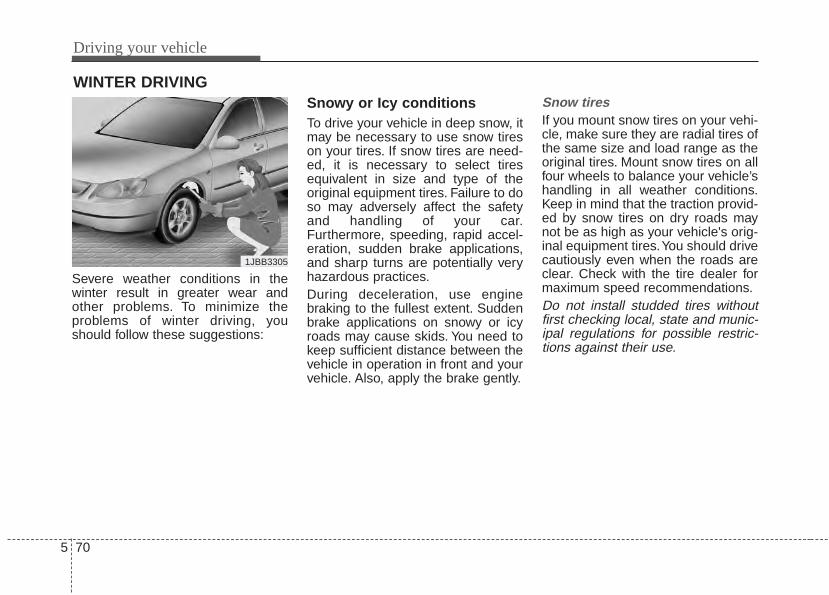
Driving your vehicle
705
Severe weather conditions in thewinter result in greater wear andother problems. To minimize theproblems of winter driving, youshould follow these suggestions:
Snowy or Icy conditionsTo drive your vehicle in deep snow, itmay be necessary to use snow tireson your tires. If snow tires are need-ed, it is necessary to select tiresequivalent in size and type of theoriginal equipment tires. Failure to doso may adversely affect the safetyand handling of your car.Furthermore, speeding, rapid accel-eration, sudden brake applications,and sharp turns are potentially veryhazardous practices.During deceleration, use enginebraking to the fullest extent. Suddenbrake applications on snowy or icyroads may cause skids. You need tokeep sufficient distance between thevehicle in operation in front and yourvehicle. Also, apply the brake gently.
Snow tiresIf you mount snow tires on your vehi-cle, make sure they are radial tires ofthe same size and load range as theoriginal tires. Mount snow tires on allfour wheels to balance your vehicle’shandling in all weather conditions.Keep in mind that the traction provid-ed by snow tires on dry roads maynot be as high as your vehicle's orig-inal equipment tires.You should drivecautiously even when the roads areclear. Check with the tire dealer formaximum speed recommendations.Do not install studded tires withoutfirst checking local, state and munic-ipal regulations for possible restric-tions against their use.
WINTER DRIVING
1JBB3305
5 71
Driving your vehicle
Use high quality ethylene gly-col coolantYour vehicle is delivered with highquality ethylene glycol coolant in thecooling system. It is the only type ofcoolant that should be used becauseit helps prevent corrosion in the cool-ing system, lubricates the waterpump and prevents freezing. Be sureto replace or replenish your coolantin accordance with the maintenanceschedule in section 7. Before winter,have your coolant tested to assurethat its freezing point is sufficient forthe temperatures anticipated duringthe winter.
Check battery and cablesWinter puts additional burdens onthe battery system. Visually inspectthe battery and cables as describedin section 7. The level of charge inyour battery can be checked by anauthorized Kia dealer or a servicestation.
Change to "winter weight" oilif necessaryIn some climates it is recommendedthat a lower viscosity "winter weight"oil be used during cold weather. Seesection 8 for recommendations. Ifyou aren't sure what weight oil youshould use, consult an authorizedKia dealer.
Check spark plugs and igni-tion systemInspect your spark plugs asdescribed in section 7 and replacethem if necessary. Also check allignition wiring and components to besure they are not cracked, worn ordamaged in any way.
To keep locks from freezingTo keep the locks from freezing,squirt an approved de-icer fluid orglycerine into the key opening. If alock is covered with ice, squirt it withan approved de-icing fluid to removethe ice. If the lock is frozen internally,you may be able to thaw it out byusing a heated key. Handle the heat-ed key with care to avoid injury.
Use approved window washeranti-freeze in systemTo keep the water in the windowwasher system from freezing, add anapproved window washer anti-freezesolution in accordance with instruc-tions on the container. Window wash-er anti-freeze is available from anauthorized Kia dealer and most autoparts outlets. Do not use enginecoolant or other types of anti-freezeas these may damage the paint fin-ish.
Driving your vehicle
725
Don't let your parking brakefreezeUnder some conditions your parkingbrake can freeze in the engagedposition. This is most likely to hap-pen when there is an accumulationof snow or ice around or near therear brakes or if the brakes are wet.If there is a risk the parking brakemay freeze, apply it only temporarilywhile you put the shift lever in P(automatic transaxle) or in first orreverse gear (manual transaxle) andblock the rear wheels so the vehiclecannot roll. Then release the parkingbrake.
Don't let ice and snow accu-mulate underneathUnder some conditions, snow andice can build up under the fendersand interfere with the steering. Whendriving in severe winter conditionswhere this may happen, you shouldperiodically check underneath thecar to be sure the movement of thefront wheels and the steering com-ponents is not obstructed.
Carry emergency equipmentDepending on the severity of theweather you should carry appropri-ate emergency equipment. Some ofthe items you may want to carryinclude tow straps or chains, flash-light, emergency flares, sand, ashovel, jumper cables, a windowscraper, gloves, ground cloth, cover-alls, a blanket, etc.
TRAILER TOWINGWe do not recommend using thisvehicle for trailer towing.
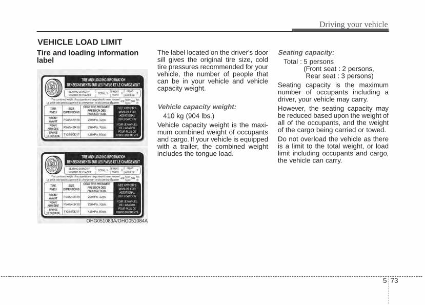
5 73
Driving your vehicle
Tire and loading informationlabel
The label located on the driver's doorsill gives the original tire size, coldtire pressures recommended for yourvehicle, the number of people thatcan be in your vehicle and vehiclecapacity weight.
Vehicle capacity weight:410 kg (904 lbs.)
Vehicle capacity weight is the maxi-mum combined weight of occupantsand cargo. If your vehicle is equippedwith a trailer, the combined weightincludes the tongue load.
Seating capacity:Total : 5 persons
(Front seat : 2 persons, Rear seat : 3 persons)
Seating capacity is the maximumnumber of occupants including adriver, your vehicle may carry.However, the seating capacity maybe reduced based upon the weight ofall of the occupants, and the weightof the cargo being carried or towed.Do not overload the vehicle as thereis a limit to the total weight, or loadlimit including occupants and cargo,the vehicle can carry.
VEHICLE LOAD LIMIT
OHG051083A/OHG051084A
Driving your vehicle
745
Towing capacity:We do not recommend using thisvehicle for trailer towing.
Cargo capacity:The cargo capacity of your vehiclewill increase or decrease dependingon the weight and the number ofoccupants and the tongue load, ifyour vehicle is equipped with a trailer.
Steps For Determining CorrectLoad Limit -1.Locate the statement "The com-
bined weight of occupants andcargo should never exceed XXX kgor XXX lbs.'' on your vehicle's plac-ard.
2.Determine the combined weight ofthe driver and passengers that willbe riding in your vehicle.
3.Subtract the combined weight ofthe driver and passengers fromXXX kg or XXX lbs.
4. The resulting figure equals theavailable amount of cargo and lug-gage load capacity. For example, ifthe "XXX" amount equals 635 kg(1400 lbs.) and there will be five 68kg (150 lbs.) passengers in yourvehicle, the amount of availablecargo and luggage load capacityis 295 kg (650 lbs).(635-340 (5 x 68) = 295 kg or1400-750 (5 x 150) = 650 lbs.)
5. Determine the combined weight ofluggage and cargo being loadedon the vehicle. That weight maynot safely exceed the availablecargo and luggage load capacitycalculated in Step 4.
6. If your vehicle will be towing a trail-er, load from your trailer will betransferred to your vehicle. Consultthis manual to determine how thisreduces the available cargo andluggage load capacity of yourvehicle.
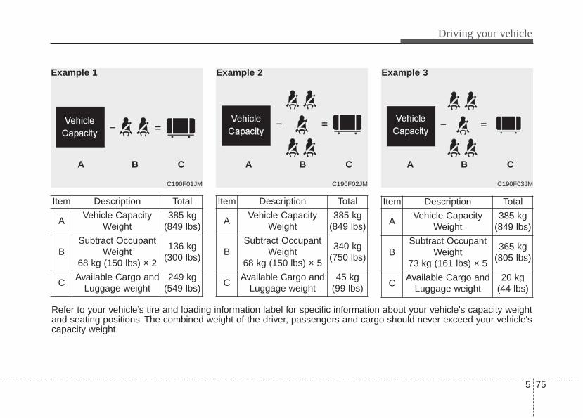
5 75
Driving your vehicle
C190F03JM
A B C
Example 3
C190F02JM
A B C
Example 2
C190F01JM
Example 1
A B C
Refer to your vehicle’s tire and loading information label for specific information about your vehicle's capacity weightand seating positions. The combined weight of the driver, passengers and cargo should never exceed your vehicle'scapacity weight.
Item Description Total
AVehicle Capacity
Weight385 kg
(849 lbs)
BSubtract Occupant
Weight 68 kg (150 lbs) × 2
136 kg(300 lbs)
CAvailable Cargo and
Luggage weight249 kg
(549 lbs)
Item Description Total
AVehicle Capacity
Weight385 kg
(849 lbs)
BSubtract Occupant
Weight 73 kg (161 lbs) × 5
365 kg(805 lbs)
CAvailable Cargo and
Luggage weight20 kg
(44 lbs)
Item Description Total
AVehicle Capacity
Weight385 kg
(849 lbs)
BSubtract Occupant
Weight 68 kg (150 lbs) × 5
340 kg(750 lbs)
CAvailable Cargo and
Luggage weight45 kg
(99 lbs)
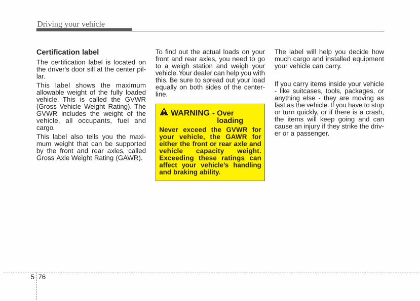
Driving your vehicle
765
Certification labelThe certification label is located onthe driver's door sill at the center pil-lar.This label shows the maximumallowable weight of the fully loadedvehicle. This is called the GVWR(Gross Vehicle Weight Rating). TheGVWR includes the weight of thevehicle, all occupants, fuel andcargo.This label also tells you the maxi-mum weight that can be supportedby the front and rear axles, calledGross Axle Weight Rating (GAWR).
To find out the actual loads on yourfront and rear axles, you need to goto a weigh station and weigh yourvehicle.Your dealer can help you withthis. Be sure to spread out your loadequally on both sides of the center-line.
The label will help you decide howmuch cargo and installed equipmentyour vehicle can carry.
If you carry items inside your vehicle- like suitcases, tools, packages, oranything else - they are moving asfast as the vehicle. If you have to stopor turn quickly, or if there is a crash,the items will keep going and cancause an injury if they strike the driv-er or a passenger.
WARNING - Over loading
Never exceed the GVWR foryour vehicle, the GAWR foreither the front or rear axle andvehicle capacity weight.Exceeding these ratings canaffect your vehicle’s handlingand braking ability.
5 77
Driving your vehicle
✽✽ NOTICEOverloading your vehicle may causedamage. Repairs would not be cov-ered by your warranty. Do not over-load your vehicle.
WARNING - Over loading
Do not overload your vehicle.Overloading your vehicle cancause heat buildup in your vehi-cle's tires and possible tire fail-ure, increased stopping dis-tances and poor vehicle han-dling--all of which may result ina crash.
WARNING - Loose cargoDo not travel with unsecuredblunt objects in the passengercompartment of your vehicle(e.g. suit cases or unsecuredchild seats). These items maystrike occupant during a sud-den stop or crash.

Driving your vehicle
785
This section will guide you in theproper loading of your vehicle and/ortrailer, to keep your loaded vehicleweight within its design rating capa-bility, with or without a trailer.Properly loading your vehicle willprovide maximum return of the vehi-cle design performance. Before load-ing your vehicle, familiarize yourselfwith the following terms for determin-ing your vehicle's weight ratings, withor without a trailer, from the vehicle'sspecifications and the compliancelabel:
Base curb weight This is the weight of the vehicleincluding a full tank of fuel and allstandard equipment. It does notinclude passengers, cargo, or option-al equipment.
Vehicle curb weightThis is the weight of your new vehiclewhen you picked it up from your deal-er plus any aftermarket equipment.
Cargo weightThis figure includes all weight addedto the Base Curb Weight, includingcargo and optional equipment.
GAW (Gross axle weight)This is the total weight placed oneach axle (front and rear) - includingvehicle curb weight and all payload.
GAWR (Gross axle weight rating)This is the maximum allowableweight that can be carried by a singleaxle (front or rear). These numbersare shown on the compliance label.The total load on each axle mustnever exceed its GAWR.
GVW (Gross vehicle weight)This is the Base Curb Weight plusactual Cargo Weight plus passen-gers.
GVWR (Gross vehicle weight rating)This is the maximum allowableweight of the fully loaded vehicle(including all options, equipment,passengers and cargo). The GVWRis shown on the certification labellocated on the driver’s door sill.
VEHICLE WEIGHT
What to do in an emergency
Road warning . . . . . . . . . . . . . . . . . . . . . . . . . . . . . . 6-2• Hazard warning flasher . . . . . . . . . . . . . . . . . . . . . . . . 6-2
In case of an emergency while driving. . . . . . . . . . 6-3• If the engine stalls at a crossroad or crossing. . . . . . . 6-3• If you have a flat tire while driving . . . . . . . . . . . . . . . 6-3• If engine stalls while driving . . . . . . . . . . . . . . . . . . . . 6-3
If the engine will not start . . . . . . . . . . . . . . . . . . . . 6-4• If engine doesn’t turn over or turns over slowly . . . . 6-4• If engine turns over normally but does not start . . . . 6-4
Emergency starting . . . . . . . . . . . . . . . . . . . . . . . . . 6-5• Jump starting. . . . . . . . . . . . . . . . . . . . . . . . . . . . . . . . . 6-5• Push-starting . . . . . . . . . . . . . . . . . . . . . . . . . . . . . . . . . 6-6
If the engine overheats . . . . . . . . . . . . . . . . . . . . . . . 6-7Tire Pressure Monitoring System (TPMS) . . . . . . 6-8
• TPMS (Tire Pressure Monitoring System) malfunction indicator . . . . . . . . . . . . . . . . . . . . . . . . 6-10
• Changing a tire with TPMS . . . . . . . . . . . . . . . . . . . . 6-11If you have a flat tire (with spare tire) . . . . . . . . . 6-14
• Jack and tools . . . . . . . . . . . . . . . . . . . . . . . . . . . . . . . 6-14• Removing and storing the spare tire . . . . . . . . . . . . . 6-15• Changing tires . . . . . . . . . . . . . . . . . . . . . . . . . . . . . . . 6-15• Wheel nut tightening torque. . . . . . . . . . . . . . . . . . . . 6-19
Towing . . . . . . . . . . . . . . . . . . . . . . . . . . . . . . . . . . . 6-22• Towing service . . . . . . . . . . . . . . . . . . . . . . . . . . . . . . . 6-22• Removable towing hook . . . . . . . . . . . . . . . . . . . . . . . 6-23• Emergency towing . . . . . . . . . . . . . . . . . . . . . . . . . . . . 6-23
6
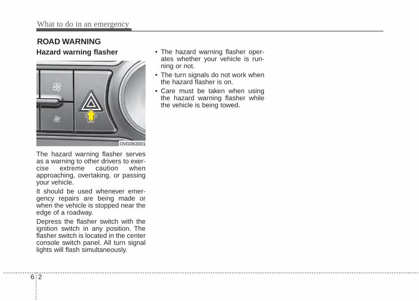
What to do in an emergency
26
Hazard warning flasher
The hazard warning flasher servesas a warning to other drivers to exer-cise extreme caution whenapproaching, overtaking, or passingyour vehicle.It should be used whenever emer-gency repairs are being made orwhen the vehicle is stopped near theedge of a roadway.Depress the flasher switch with theignition switch in any position. Theflasher switch is located in the centerconsole switch panel. All turn signallights will flash simultaneously.
• The hazard warning flasher oper-ates whether your vehicle is run-ning or not.
• The turn signals do not work whenthe hazard flasher is on.
• Care must be taken when usingthe hazard warning flasher whilethe vehicle is being towed.
ROAD WARNING
OVG063001
6 3
What to do in an emergency
If the engine stalls at a cross-road or crossingIf the engine stalls at a crossroad orcrossing, set the shift lever in the N(Neutral) position and then push thevehicle to a safe place.
If you have a flat tire whiledrivingIf a tire goes flat while you are driv-ing:1.Take your foot off the accelerator
pedal and let the vehicle slowdown while driving straight ahead.Do not apply the brakes immedi-ately or attempt to pull off the roadas this may cause a loss of control.When the vehicle has slowed downto such a speed that it is safe to doso, brake carefully and pull off theroad. Drive off the road as far aspossible and park on a firm levelground. If you are on a dividedhighway, do not park in the medianarea between the two traffic lanes.
2.When the vehicle is stopped, turnon your emergency hazard flash-ers, set the parking brake and putthe transaxle in P (automatictransaxle).
3.Have all passengers get out of thevehicle. Be sure they all get out onthe side of the vehicle that is awayfrom traffic.
4.When changing a flat tire, followthe instruction provided later in thissection.
If engine stalls while driving1.Reduce your speed gradually,
keeping a straight line. Move cau-tiously off the road to a safe place.
2.Turn on your emergency flashers.3.Try to start the engine again. If your
vehicle will not start, contact anauthorized Kia dealer or seek otherqualified assistance.
IN CASE OF AN EMERGENCY WHILE DRIVING
What to do in an emergency
46
IF THE ENGINE WILL NOT STARTIf the engine doesn't turn overor turns over slowly1.If your vehicle has an automatic
transaxle, be sure the shift lever isin N (Neutral) or P (Park) and theemergency brake is set.
2.Check the battery connections tobe sure they are clean and tight.
3.Turn on the interior light. If the lightdims or goes out when you operatethe starter, the battery is dis-charged.
4.Check the starter connections tobe sure they are securely tight-ened.
5.Do not push or pull the vehicle tostart it. See instructions for "Jumpstarting".
If engine turns over normallybut does not start1.Check fuel level.2.With the ignition switch in the
LOCK position, check all connec-tors at the ignition coil and sparkplugs. Reconnect any that may bedisconnected or loose.
3.Check the fuel line in the enginecompartment.
4.If the engine still does not start, callan authorized Kia dealer or seekother qualified assistance.
WARNING - Push/pull start
Do not push or pull the vehicleto start it. Push or pull startingmay cause the catalytic con-verter to overload and create afire hazard.
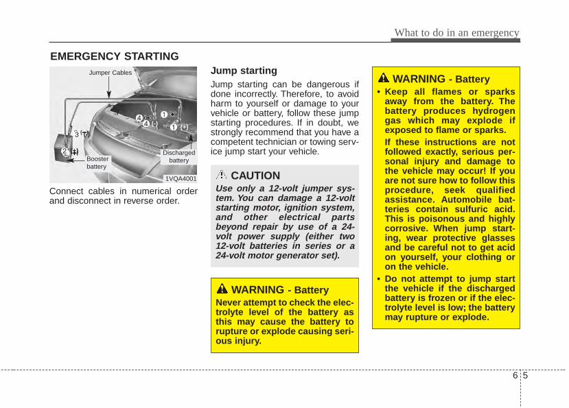
6 5
What to do in an emergency
EMERGENCY STARTING
Connect cables in numerical orderand disconnect in reverse order.
Jump starting Jump starting can be dangerous ifdone incorrectly. Therefore, to avoidharm to yourself or damage to yourvehicle or battery, follow these jumpstarting procedures. If in doubt, westrongly recommend that you have acompetent technician or towing serv-ice jump start your vehicle.
CAUTIONUse only a 12-volt jumper sys-tem. You can damage a 12-voltstarting motor, ignition system,and other electrical partsbeyond repair by use of a 24-volt power supply (either two12-volt batteries in series or a24-volt motor generator set).
WARNING - Battery• Keep all flames or sparks
away from the battery. Thebattery produces hydrogengas which may explode ifexposed to flame or sparks.If these instructions are notfollowed exactly, serious per-sonal injury and damage tothe vehicle may occur! If youare not sure how to follow thisprocedure, seek qualifiedassistance. Automobile bat-teries contain sulfuric acid.This is poisonous and highlycorrosive. When jump start-ing, wear protective glassesand be careful not to get acidon yourself, your clothing oron the vehicle.
• Do not attempt to jump startthe vehicle if the dischargedbattery is frozen or if the elec-trolyte level is low; the batterymay rupture or explode.
WARNING - BatteryNever attempt to check the elec-trolyte level of the battery asthis may cause the battery torupture or explode causing seri-ous injury.
1VQA4001
Dischargedbattery
Jumper Cables
Boosterbattery
(-)
(+)
(+)(-)
What to do in an emergency
66
Jump starting procedure 1.Make sure the booster battery is
12-volt and that its negative termi-nal is grounded.
2.If the booster battery is in anothervehicle, do not allow the vehicles tocome in contact.
3.Turn off all unnecessary electricalloads.
4.Connect the jumper cables in theexact sequence shown in the illus-tration. First connect one end of ajumper cable to the positive termi-nal of the discharged battery (1),then connect the other end to thepositive terminal of the boosterbattery (2).Proceed to connect one end of theother jumper cable to the negativeterminal of the booster battery (3),then the other end to a solid, sta-tionary, metallic point (for example,the engine lifting bracket) awayfrom the battery (4). Do not con-nect it to or near any part thatmoves when the engine is cranked.
Do not allow the jumper cables tocontact anything except the correctbattery terminals or the correctground. Do not lean over the bat-tery when making connections.
5.Start the engine of the vehicle withthe booster battery and let it run at2,000 rpm, then start the engine ofthe vehicle with the dischargedbattery.
If the cause of your battery discharg-ing is not apparent, you should haveyour vehicle checked by an author-ized Kia dealer.
Push-starting Vehicles equipped with automatictransaxle lock system cannot bepush-started.Follow the directions in this sectionfor jump-starting.
CAUTION - Batterycables
Do not connect the jumpercable from the negative terminalof the booster battery to thenegative terminal of the dis-charged battery. This can causethe discharged battery to over-heat and crack, releasing bat-tery acid.
WARNINGNever tow a vehicle to start itbecause the sudden surge for-ward when the engine startscould cause a collision with thetow vehicle.
6 7
What to do in an emergency
IF THE ENGINE OVERHEATSIf your temperature gauge indicatesoverheating, you experience a lossof power, or hear loud pinging orknocking, the engine will probably betoo hot. If this happens, you should:
1.Pull off the road and stop as soonas it is safe to do so.
2.Place the shift lever in P (Park,automatic transaxle) and set theparking brake. If the air condition-ing is on, turn it off.
3.If engine coolant is running outunder the vehicle or steam is com-ing out from underneath the hood,stop the engine. Do not open thehood until the coolant has stoppedrunning or the steaming hasstopped. If there is no visible lossof engine coolant and no steam,leave the engine running andcheck to be sure the engine cool-ing fan is operating. If the fan is notrunning, turn the engine off.
4.Check to see if the water pumpdrive belt is missing. If it is notmissing, check to see that it istight. If the drive belt seems to besatisfactory, check for coolant leak-ing from the radiator, hoses orunder the vehicle. (If the air condi-tioning had been in use, it is nor-mal for cold water to be drainingfrom it when you stop).
5.If the water pump drive belt is bro-ken or engine coolant is leakingout, stop the engine immediatelyand call the nearest authorized Kiadealer for assistance.
6.If you cannot find the cause of theoverheating, wait until the enginetemperature has returned to nor-mal. Then, if coolant has been lost,carefully add coolant to the reser-voir to bring the fluid level in thereservoir up to the halfway mark.
7.Proceed with caution, keepingalert for further signs of overheat-ing. If overheating happens again,call an authorized Kia dealer forassistance.
WARNINGWhile the engine is running,keep hair, hands and clothingaway from moving parts suchas the fan and drive belts to pre-vent injury.
WARNINGDo not remove the radiator capwhen the engine is hot. Thismay result in coolant beingblown out of the opening andcause serious burns.
CAUTIONSerious loss of coolant indi-cates there is a leak in the cool-ing system and this should bechecked as soon as possible byan authorized Kia dealer.
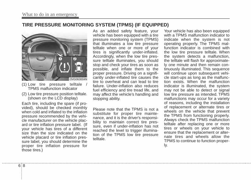
What to do in an emergency
86
TIRE PRESSURE MONITORING SYSTEM (TPMS) (IF EQUIPPED)
(1) Low tire pressure telltale / TPMS malfunction indicator
(2) Low tire pressure position telltale.(shown on the LCD display)
Each tire, including the spare (if pro-vided), should be checked monthlywhen cold and inflated to the inflationpressure recommended by the vehi-cle manufacturer on the vehicle plac-ard or tire inflation pressure label. (Ifyour vehicle has tires of a differentsize than the size indicated on thevehicle placard or tire inflation pres-sure label, you should determine theproper tire inflation pressure forthose tires.)
As an added safety feature, yourvehicle has been equipped with a tirepressure monitoring system (TPMS)that illuminates a low tire pressuretelltale when one or more of yourtires is significantly under-inflated.Accordingly, when the low tire pres-sure telltale illuminates, you shouldstop and check your tires as soon aspossible, and inflate them to theproper pressure. Driving on a signifi-cantly under-inflated tire causes thetire to overheat and can lead to tirefailure. Under-inflation also reducesfuel efficiency and tire tread life, andmay affect the vehicle’s handling andstopping ability.
Please note that the TPMS is not asubstitute for proper tire mainte-nance, and it is the driver’s responsi-bility to maintain correct tire pres-sure, even if under-inflation has notreached the level to trigger illumina-tion of the TPMS low tire pressuretelltale.
Your vehicle has also been equippedwith a TPMS malfunction indicator toindicate when the system is notoperating properly. The TPMS mal-function indicator is combined withthe low tire pressure telltale. Whenthe system detects a malfunction,the telltale will flash for approximate-ly one minute and then remain con-tinuously illuminated. This sequencewill continue upon subsequent vehi-cle start-ups as long as the malfunc-tion exists. When the malfunctionindicator is illuminated, the systemmay not be able to detect or signallow tire pressure as intended. TPMSmalfunctions may occur for a varietyof reasons, including the installationof replacement or alternate tires orwheels on the vehicle that preventthe TPMS from functioning properly.Always check the TPMS malfunctiontelltale after replacing one or moretires or wheels on your vehicle toensure that the replacement or alter-nate tires and wheels allow theTPMS to continue to function proper-ly.
OVG063004N
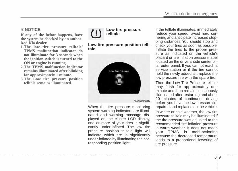
6 9
What to do in an emergency
✽✽ NOTICEIf any of the below happens, havethe system be checked by an author-ized Kia dealer.1.The low tire pressure telltale/
TPMS malfunction indicator donot illuminate for 3 seconds whenthe ignition switch is turned to theON or engine is running.
2.The TPMS malfunction indicatorremains illuminated after blinkingfor approximately 1 minute.
3.The Low tire pressure positiontelltale remains illuminated.
Low tire pressuretelltale
Low tire pressure position tell-tale
When the tire pressure monitoringsystem warning indicators are illumi-nated and warning massage dis-played on the cluster LCD display,one or more of your tires is signifi-cantly under-inflated. The low tirepressure position telltale light willindicate which tire is significantlyunder-inflated by illuminating the cor-responding position light.
If the telltale illuminates, immediatelyreduce your speed, avoid hard cor-nering and anticipate increased stop-ping distances. You should stop andcheck your tires as soon as possible.Inflate the tires to the proper pres-sure as indicated on the vehicle’splacard or tire inflation pressure labellocated on the driver’s side center pil-lar outer panel. If you cannot reach aservice station or if the tire cannothold the newly added air, replace thelow pressure tire with the spare tire.Then the Low Tire Pressure telltalemay flash for approximately oneminute and then remain continuouslyilluminated after restarting and about20 minutes of continuous drivingbefore you have the low pressure tirerepaired and replaced on the vehicle.In winter or cold weather, the low tirepressure telltale may be illuminated ifthe tire pressure was adjusted to therecommended tire inflation pressurein warm weather. It does not meanyour TPMS is malfunctioningbecause the decreased temperatureleads to a proportional lowering oftire pressure.
OVG043307N
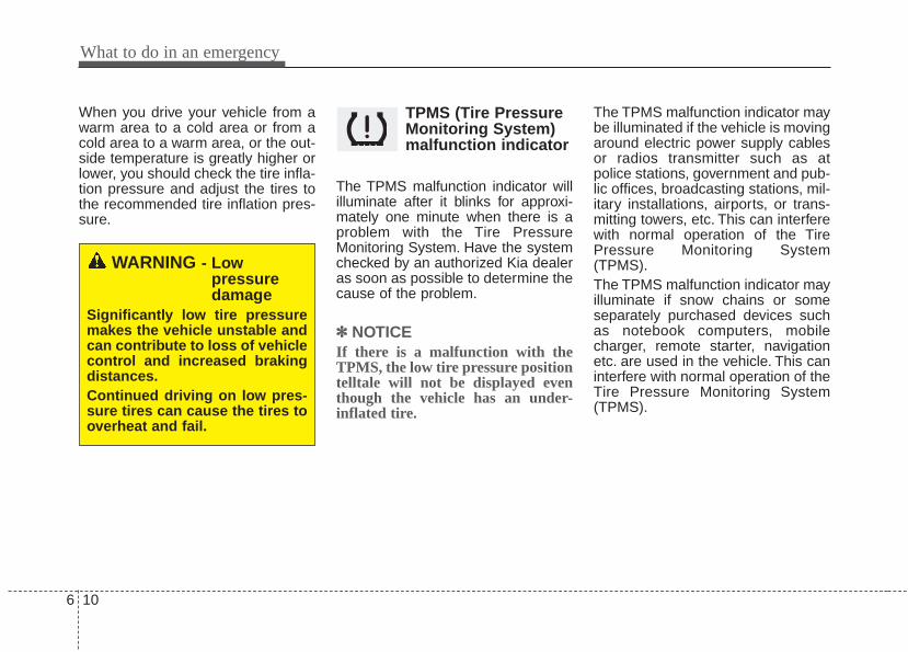
What to do in an emergency
106
When you drive your vehicle from awarm area to a cold area or from acold area to a warm area, or the out-side temperature is greatly higher orlower, you should check the tire infla-tion pressure and adjust the tires tothe recommended tire inflation pres-sure.
TPMS (Tire PressureMonitoring System)malfunction indicator
The TPMS malfunction indicator willilluminate after it blinks for approxi-mately one minute when there is aproblem with the Tire PressureMonitoring System. Have the systemchecked by an authorized Kia dealeras soon as possible to determine thecause of the problem.
✽✽ NOTICEIf there is a malfunction with theTPMS, the low tire pressure positiontelltale will not be displayed eventhough the vehicle has an under-inflated tire.
The TPMS malfunction indicator maybe illuminated if the vehicle is movingaround electric power supply cablesor radios transmitter such as atpolice stations, government and pub-lic offices, broadcasting stations, mil-itary installations, airports, or trans-mitting towers, etc. This can interferewith normal operation of the TirePressure Monitoring System(TPMS).The TPMS malfunction indicator mayilluminate if snow chains or someseparately purchased devices suchas notebook computers, mobilecharger, remote starter, navigationetc. are used in the vehicle. This caninterfere with normal operation of theTire Pressure Monitoring System(TPMS).
WARNING - Low pressuredamage
Significantly low tire pressuremakes the vehicle unstable andcan contribute to loss of vehiclecontrol and increased brakingdistances.Continued driving on low pres-sure tires can cause the tires tooverheat and fail.

6 11
What to do in an emergency
Changing a tire with TPMSIf you have a flat tire, the Low TirePressure will come on. Have the flattire repaired by an authorized Kiadealer as soon as possible orreplace the flat tire with the sparetire.
Each wheel is equipped with a tirepressure sensor mounted inside thetire behind the valve stem. You mustuse TPMS specific wheels. It is rec-ommended that you always haveyour tires serviced by an authorizedKia dealer.
Even if you replace the low pressuretire with the spare tire, the Low TirePressure telltale will blink or remainon until the low pressure tire isrepaired and placed on the vehicle.After you replace the low pressuretire with the TPMS spare tire, theLow Tire Pressure telltale may blinkor illuminate after a few minutesbecause the TPMS sensor mountedon the spare wheel is not initiated.Once the low pressure tire is reinflat-ed to the recommended pressureand installed on the vehicle or theTPMS sensor mounted on thereplaced spare wheel is initiated byan authorized Kia dealer, the TPMSmalfunction indicator and the low tirepressure telltale will extinguish withina few minutes of driving.If the indicator is not extinguishedafter a few minutes of driving, pleasevisit an authorized Kia dealer.
CAUTIONNEVER use a puncture-repair-ing agent to repair and/or inflatea low pressure tire. The tiresealant can damage the tirepressure sensor. If used, youwill have to replace the tire pres-sure sensor.
CAUTIONIf an original mounted tire isreplaced with the spare tire, theTPMS sensor on the replacedspare wheel should be initiatedand the TPMS sensor on theoriginal mounted wheel shouldbe deactivated. If the TPMS sen-sor on the original mountedwheel located in the spare tirecarrier still activates, the tirepressure monitoring systemmay not operate properly. Havethe tire with TPMS serviced orreplaced by an authorized Kiadealer.
What to do in an emergency
126
You may not be able to identify a lowtire by simply looking at it. Alwaysuse a good quality tire pressuregauge to measure the tire's inflationpressure. Please note that a tire thatis hot (from being driven) will have ahigher pressure measurement than atire that is cold (from sitting station-ary for at least 3 hours and drivenless than 1 mile (1.6 km) during that3 hour period).Allow the tire to cool before measur-ing the inflation pressure. Always besure the tire is cold before inflating tothe recommended pressure.
A cold tire means the vehicle hasbeen sitting for 3 hours and driven forless than 1.6 km (1 mile) in that 3hour period.
CAUTIONDo not use any tire sealant ifyour vehicle is equipped with aTire Pressure MonitoringSystem. The liquid sealant candamage the tire pressure sen-sors.
WARNING - TPMS• The TPMS cannot alert you to
severe and sudden tire dam-age caused by external fac-tors such as nails or roaddebris.
• If you feel any vehicle instabil-ity, immediately take your footoff the accelerator, apply thebrakes gradually and withlight force, and slowly move toa safe position off the road.
6 13
What to do in an emergency
This device complies with IndustryCanada Standard RSS-210.Operation is subject to the followingtwo conditions:1.This device may not cause harmful
interference, and 2.This device must accept any inter-
ference received, including inter-ference that may cause undesiredoperation.
WARNING - ProtectingTPMS
Tampering with, modifying, ordisabling the Tire PressureMonitoring System (TPMS)components may interfere withthe system's ability to warn thedriver of low tire pressure con-ditions and/or TPMS malfunc-tions. Tampering with, modify-ing, or disabling the TirePressure Monitoring System(TPMS) components may voidthe warranty for that portion ofthe vehicle.
WARNING Changes or modifications notexpressly approved by the partyresponsible for compliancecould void the user’s authorityto operate the equipment.
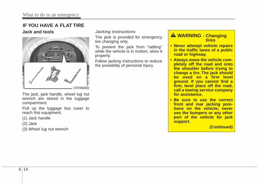
What to do in an emergency
146
IF YOU HAVE A FLAT TIREJack and tools
The jack, jack handle, wheel lug nutwrench are stored in the luggagecompartment.Pull up the luggage box cover toreach this equipment.(1) Jack handle(2) Jack(3) Wheel lug nut wrench
Jacking instructions The jack is provided for emergencytire changing only.To prevent the jack from “rattling”while the vehicle is in motion, store itproperly.Follow jacking instructions to reducethe possibility of personal injury.
WARNING - Changingtires
• Never attempt vehicle repairsin the traffic lanes of a publicroad or highway.
• Always move the vehicle com-pletely off the road and ontothe shoulder before trying tochange a tire. The jack shouldbe used on a firm levelground. If you cannot find afirm, level place off the road,call a towing service companyfor assistance.
• Be sure to use the correctfront and rear jacking posi-tions on the vehicle; neveruse the bumpers or any otherpart of the vehicle for jacksupport.
(Continued)
OTF060002
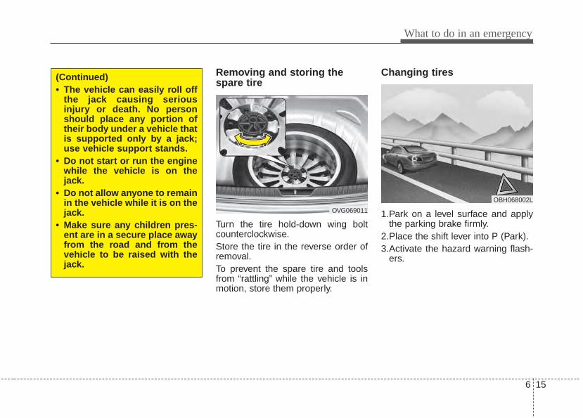
6 15
What to do in an emergency
Removing and storing thespare tire
Turn the tire hold-down wing boltcounterclockwise.Store the tire in the reverse order ofremoval.To prevent the spare tire and toolsfrom “rattling” while the vehicle is inmotion, store them properly.
Changing tires
1.Park on a level surface and applythe parking brake firmly.
2.Place the shift lever into P (Park).3.Activate the hazard warning flash-
ers.
(Continued)• The vehicle can easily roll off
the jack causing seriousinjury or death. No personshould place any portion oftheir body under a vehicle thatis supported only by a jack;use vehicle support stands.
• Do not start or run the enginewhile the vehicle is on thejack.
• Do not allow anyone to remainin the vehicle while it is on thejack.
• Make sure any children pres-ent are in a secure place awayfrom the road and from thevehicle to be raised with thejack.
OVG069011
OBH068002L
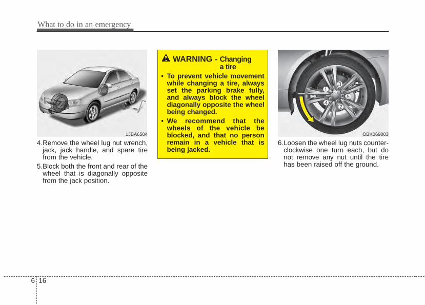
What to do in an emergency
166
4.Remove the wheel lug nut wrench,jack, jack handle, and spare tirefrom the vehicle.
5.Block both the front and rear of thewheel that is diagonally oppositefrom the jack position.
6.Loosen the wheel lug nuts counter-clockwise one turn each, but donot remove any nut until the tirehas been raised off the ground.
1JBA6504
WARNING - Changing a tire
• To prevent vehicle movementwhile changing a tire, alwaysset the parking brake fully,and always block the wheeldiagonally opposite the wheelbeing changed.
• We recommend that thewheels of the vehicle beblocked, and that no personremain in a vehicle that isbeing jacked.
OBK069003
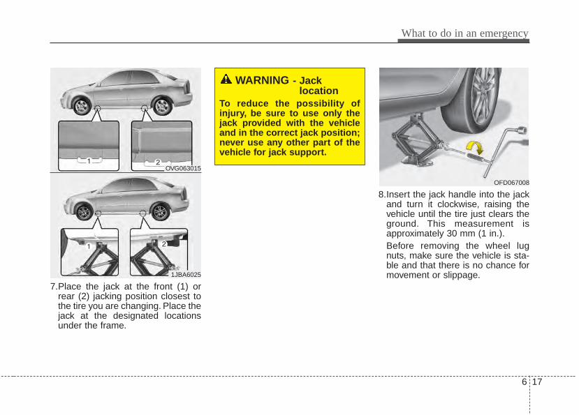
6 17
What to do in an emergency
7.Place the jack at the front (1) orrear (2) jacking position closest tothe tire you are changing. Place thejack at the designated locationsunder the frame.
8.Insert the jack handle into the jackand turn it clockwise, raising thevehicle until the tire just clears theground. This measurement isapproximately 30 mm (1 in.).Before removing the wheel lugnuts, make sure the vehicle is sta-ble and that there is no chance formovement or slippage.
WARNING - Jack location
To reduce the possibility ofinjury, be sure to use only thejack provided with the vehicleand in the correct jack position;never use any other part of thevehicle for jack support.
OFD067008
OVG063015
1JBA6025
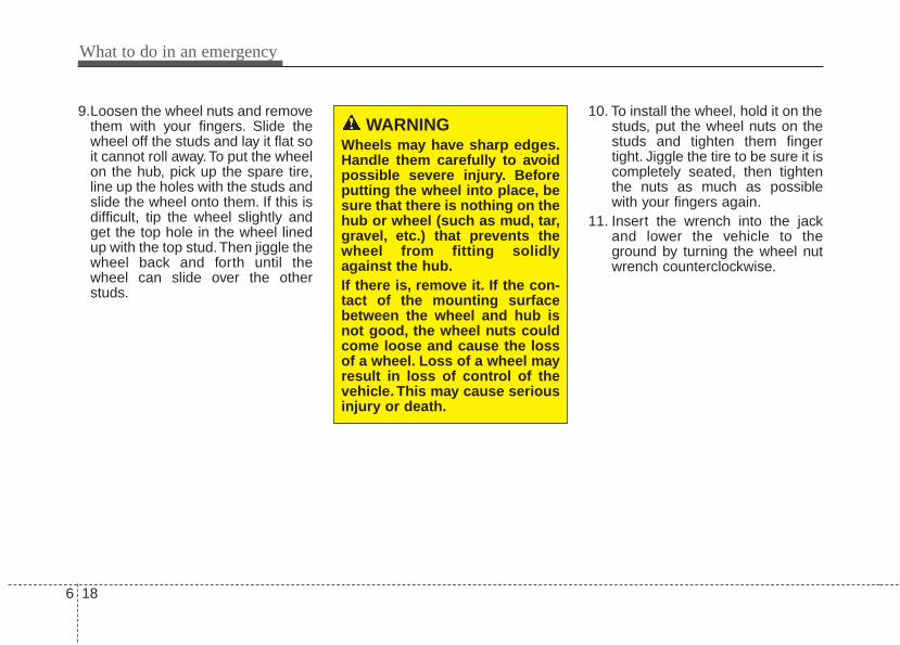
What to do in an emergency
186
9.Loosen the wheel nuts and removethem with your fingers. Slide thewheel off the studs and lay it flat soit cannot roll away. To put the wheelon the hub, pick up the spare tire,line up the holes with the studs andslide the wheel onto them. If this isdifficult, tip the wheel slightly andget the top hole in the wheel linedup with the top stud.Then jiggle thewheel back and forth until thewheel can slide over the otherstuds.
10. To install the wheel, hold it on thestuds, put the wheel nuts on thestuds and tighten them fingertight. Jiggle the tire to be sure it iscompletely seated, then tightenthe nuts as much as possiblewith your fingers again.
11. Insert the wrench into the jackand lower the vehicle to theground by turning the wheel nutwrench counterclockwise.
WARNINGWheels may have sharp edges.Handle them carefully to avoidpossible severe injury. Beforeputting the wheel into place, besure that there is nothing on thehub or wheel (such as mud, tar,gravel, etc.) that prevents thewheel from fitting solidlyagainst the hub.If there is, remove it. If the con-tact of the mounting surfacebetween the wheel and hub isnot good, the wheel nuts couldcome loose and cause the lossof a wheel. Loss of a wheel mayresult in loss of control of thevehicle. This may cause seriousinjury or death.

6 19
What to do in an emergency
Then position the wrench as shownin the drawing and tighten the wheelnuts. Be sure the socket is seatedcompletely over the nut. Do not standon the wrench handle or use anextension pipe over the wrench han-dle. Go around the wheel tighteningevery nut following the numericalsequence shown in the image untilthey are all tight. Then double-checkeach nut for tightness. After changingwheels, have an authorized Kia deal-er tighten the wheel nuts to theirproper torque as soon as possible.
Wheel nut tightening torque:9~11 kg·m (65~79 lb·ft)
If you have a tire gauge, remove thevalve cap and check the air pressure.If the pressure is lower than recom-mended, drive slowly to the nearestservice station and inflate to the cor-rect pressure. If it is too high, adjustit until it is correct. Always reinstallthe valve cap after checking oradjusting the tire pressure. If the capis not replaced, dust and dirt may getinto the tire valve and air may leakfrom the tire. If you lose a valve cap,buy another and install it as soon aspossible.After you have changed the wheels,always secure the flat tire in its placeand return the jack and tools to theirproper storage locations.
OBK069016
CAUTIONYour vehicle has metric threadson the wheel studs and nuts.Make certain during wheelremoval that the same nuts thatwere removed are reinstalled -or, if replaced, that nuts withmetric threads and the samechamfer configuration are used.Installation of a non-metricthread nut on a metric stud orvice-versa will not secure thewheel to the hub properly andwill damage the stud so that itmust be replaced.Note that most lug nuts do nothave metric threads. Be sure touse extreme care in checkingfor thread style before installingaftermarket lug nuts or wheels.If in doubt, consult an author-ized Kia dealer.
What to do in an emergency
206
To prevent the jack, jack handle,wheel lug nut wrench and spare tirefrom rattling while the vehicle is inmotion, store them properly.
Important - use of compact sparetire (if equipped)Your vehicle is equipped with a com-pact spare tire. This compact sparetire takes up less space than a regu-lar-size tire. This tire is smaller than aconventional tire and is designed fortemporary use only.
The compact spare should be inflat-ed to 420 kPa (60 psi).
✽✽ NOTICECheck the inflation pressure afterinstalling the spare tire. Adjust it tothe specified pressure, as necessary.
CAUTION• You should drive carefully
when the compact spare is inuse. The compact spareshould be replaced by theproper conventional tire andrim at the first opportunity.
• The operation of this vehicleis not recommended withmore than one compact sparetire in use at the same time.
WARNINGThe compact spare tire is foremergency use only. Do notoperate your vehicle on thiscompact spare at speeds over50 mph (80 km/h). The originaltire should be repaired orreplaced as soon as possible toavoid failure of the spare possi-bly leading to personal injury ordeath.
WARNING - Wheel studsIf the studs are damaged, theymay lose their ability to retainthe wheel.This could lead to theloss of the wheel and a collisionresulting in serious injuries.
WARNING - Inadequatespare tire pressure
Check the inflation pressuresas soon as possible afterinstalling the spare tire. Adjustit to the specified pressure, ifnecessary. Refer to “Tires andwheels” in section 8.
6 21
What to do in an emergency
When using a compact spare tire,observe the following precautions:• Under no circumstances should
you exceed 80 km/h (50 mph); ahigher speed could damage thetire.
• Ensure that you drive slowlyenough for the road conditions toavoid all hazards. Any road hazard,such as a pothole or debris, couldseriously damage the compactspare.
• Any continuous road use of this tirecould result in tire failure, loss ofvehicle control, and possible per-sonal injury.
• Do not exceed the vehicle’s maxi-mum load rating or the load-carry-ing capacity shown on the sidewallof the compact spare tire.
• Avoid driving over obstacles. Thecompact spare tire diameter issmaller than the diameter of a con-ventional tire and reduces theground clearance approximately25 mm (1 inch), which could resultin damage to the vehicle.
• Do not take this vehicle through anautomatic vehicle wash while thecompact spare tire is installed.
• Do not use the compact spare tireon any other vehicle because thistire has been designed especiallyfor your vehicle.
• The compact spare tire’s tread lifeis shorter than a regular tire.Inspect your compact spare tireregularly and replace worn com-pact spare tires with the same sizeand design, mounted on the samewheel.
• The compact spare tire should notbe used on any other wheels, norshould standard tires, snow tires,wheel covers or trim rings be usedwith the compact spare wheel. Ifsuch use is attempted, damage tothese items or other vehicle com-ponents may occur.
• Do not use more than one compactspare tire at a time.
• Do not tow a trailer while the com-pact spare tire is installed.
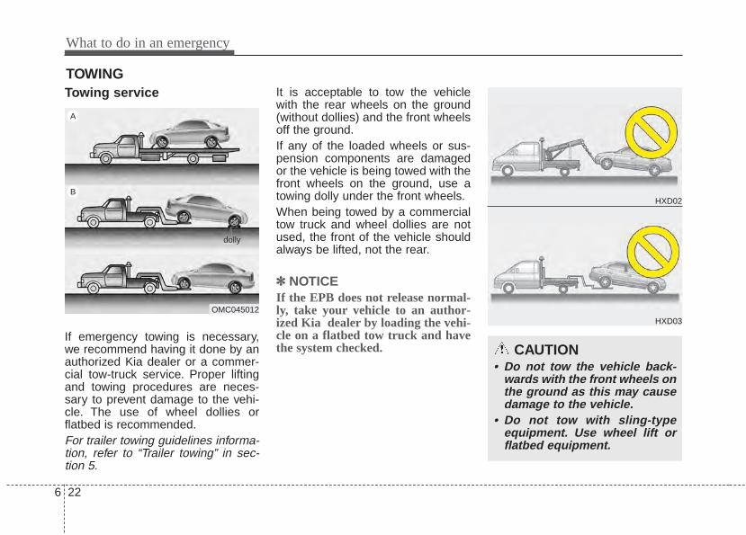
What to do in an emergency
226
TOWINGTowing service
If emergency towing is necessary,we recommend having it done by anauthorized Kia dealer or a commer-cial tow-truck service. Proper liftingand towing procedures are neces-sary to prevent damage to the vehi-cle. The use of wheel dollies orflatbed is recommended.For trailer towing guidelines informa-tion, refer to “Trailer towing” in sec-tion 5.
It is acceptable to tow the vehiclewith the rear wheels on the ground(without dollies) and the front wheelsoff the ground.If any of the loaded wheels or sus-pension components are damagedor the vehicle is being towed with thefront wheels on the ground, use atowing dolly under the front wheels.When being towed by a commercialtow truck and wheel dollies are notused, the front of the vehicle shouldalways be lifted, not the rear.
✽✽ NOTICEIf the EPB does not release normal-ly, take your vehicle to an author-ized Kia dealer by loading the vehi-cle on a flatbed tow truck and havethe system checked. CAUTION
• Do not tow the vehicle back-wards with the front wheels onthe ground as this may causedamage to the vehicle.
• Do not tow with sling-typeequipment. Use wheel lift orflatbed equipment.
OMC045012
A
B
dolly
HXD02
HXD03
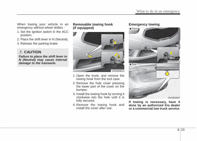
6 23
What to do in an emergency
When towing your vehicle in anemergency without wheel dollies :1. Set the ignition switch in the ACC
position.2. Place the shift lever in N (Neutral).3. Release the parking brake.
Removable towing hook (if equipped)
1. Open the trunk, and remove thetowing hook from the tool case.
2. Remove the hole cover pressingthe lower part of the cover on thebumper.
3. Install the towing hook by turning itclockwise into the hole until it isfully secured.
4. Remove the towing hook andinstall the cover after use.
Emergency towing
If towing is necessary, have itdone by an authorized Kia dealeror a commercial tow truck service.
CAUTIONFailure to place the shift lever inN (Neutral) may cause internaldamage to the transaxle.
OVG063013
OVG063014
OVG063007
■ Front
■ Rear
What to do in an emergency
246
If towing service is not available in anemergency, your vehicle may betemporarily towed using a cable orchain secured to the emergency tow-ing hook under the rear of the vehi-cle. Use extreme caution when tow-ing the vehicle. A driver must be inthe vehicle to steer it and operate thebrakes.Towing in this manner may be doneonly on hard-surfaced roads for ashort distance and at low speeds.Also, the wheels, axles, power train,steering and brakes must all be ingood condition.• Do not use the tow hooks to pull a
vehicle out of mud, sand or otherconditions from which the vehiclecannot be driven out under its ownpower.
• Avoid towing a vehicle heavier thanthe vehicle doing the towing.
• The drivers of both vehicles shouldcommunicate with each other fre-quently.
• Before emergency towing, checkthat the hook is not broken or dam-aged.
• Fasten the towing cable or chainsecurely to the hook.
• Do not jerk the hook. Apply steadyand even force.
• To avoid damaging the hook, donot pull from the side or at a verti-cal angle. Always pull straightahead.
CAUTION• Attach a towing strap to the
tow hook.• Using a portion of the vehicle
other than the tow hooks fortowing may damage the bodyof your vehicle.
• Use only a cable or chainspecifically intended for usein towing vehicles. Securelyfasten the cable or chain tothe towing hook provided.
WARNING Use extreme caution when tow-ing the vehicle.• Avoid sudden starts or erratic
driving maneuvers whichwould place excessive stresson the emergency towinghook and towing cable orchain. The hook and towingcable or chain may break andcause serious injury or dam-age.
• If the disabled vehicle isunable to be moved, do notforcibly continue the towing.Contact an authorized Kiadealer or a commercial towtruck service for assistance.
• Tow the vehicle as straightahead as possible.
• Keep away from the vehicleduring towing.
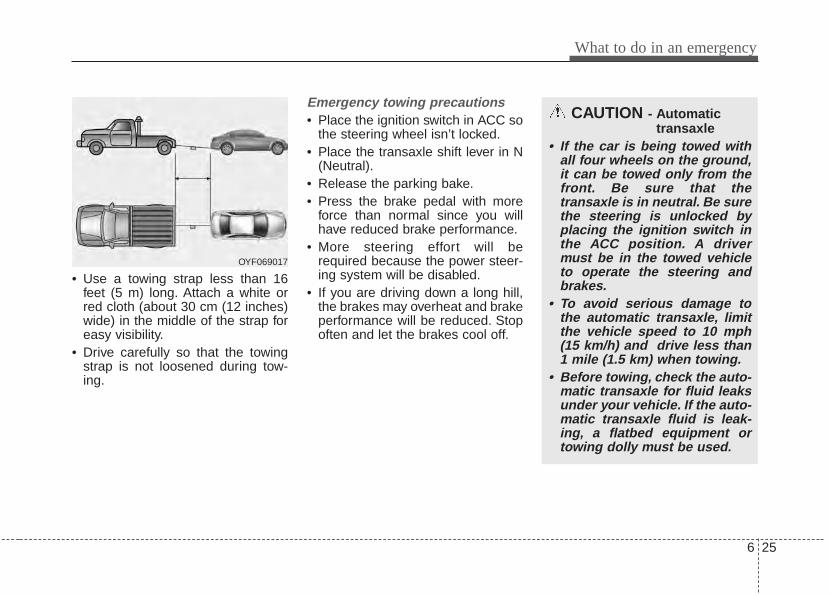
6 25
What to do in an emergency
• Use a towing strap less than 16feet (5 m) long. Attach a white orred cloth (about 30 cm (12 inches)wide) in the middle of the strap foreasy visibility.
• Drive carefully so that the towingstrap is not loosened during tow-ing.
Emergency towing precautions• Place the ignition switch in ACC so
the steering wheel isn’t locked.• Place the transaxle shift lever in N
(Neutral).• Release the parking bake.• Press the brake pedal with more
force than normal since you willhave reduced brake performance.
• More steering effort will berequired because the power steer-ing system will be disabled.
• If you are driving down a long hill,the brakes may overheat and brakeperformance will be reduced. Stopoften and let the brakes cool off.
CAUTION - Automatictransaxle
• If the car is being towed withall four wheels on the ground,it can be towed only from thefront. Be sure that thetransaxle is in neutral. Be surethe steering is unlocked byplacing the ignition switch inthe ACC position. A drivermust be in the towed vehicleto operate the steering andbrakes.
• To avoid serious damage tothe automatic transaxle, limitthe vehicle speed to 10 mph(15 km/h) and drive less than1 mile (1.5 km) when towing.
• Before towing, check the auto-matic transaxle for fluid leaksunder your vehicle. If the auto-matic transaxle fluid is leak-ing, a flatbed equipment ortowing dolly must be used.
OYF069017
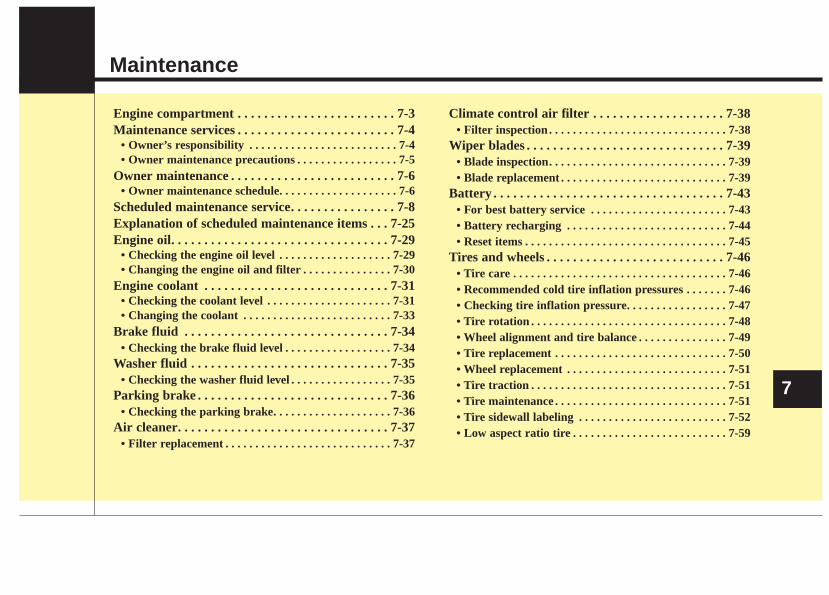
Maintenance
7
Engine compartment . . . . . . . . . . . . . . . . . . . . . . . . 7-3Maintenance services . . . . . . . . . . . . . . . . . . . . . . . . 7-4
• Owner’s responsibility . . . . . . . . . . . . . . . . . . . . . . . . . 7-4• Owner maintenance precautions . . . . . . . . . . . . . . . . . 7-5
Owner maintenance . . . . . . . . . . . . . . . . . . . . . . . . . 7-6• Owner maintenance schedule. . . . . . . . . . . . . . . . . . . . 7-6
Scheduled maintenance service. . . . . . . . . . . . . . . . 7-8Explanation of scheduled maintenance items . . . 7-25Engine oil. . . . . . . . . . . . . . . . . . . . . . . . . . . . . . . . . 7-29
• Checking the engine oil level . . . . . . . . . . . . . . . . . . . 7-29• Changing the engine oil and filter . . . . . . . . . . . . . . . 7-30
Engine coolant . . . . . . . . . . . . . . . . . . . . . . . . . . . . 7-31• Checking the coolant level . . . . . . . . . . . . . . . . . . . . . 7-31• Changing the coolant . . . . . . . . . . . . . . . . . . . . . . . . . 7-33
Brake fluid . . . . . . . . . . . . . . . . . . . . . . . . . . . . . . . 7-34• Checking the brake fluid level . . . . . . . . . . . . . . . . . . 7-34
Washer fluid . . . . . . . . . . . . . . . . . . . . . . . . . . . . . . 7-35• Checking the washer fluid level . . . . . . . . . . . . . . . . . 7-35
Parking brake . . . . . . . . . . . . . . . . . . . . . . . . . . . . . 7-36• Checking the parking brake. . . . . . . . . . . . . . . . . . . . 7-36
Air cleaner. . . . . . . . . . . . . . . . . . . . . . . . . . . . . . . . 7-37• Filter replacement . . . . . . . . . . . . . . . . . . . . . . . . . . . . 7-37
Climate control air filter . . . . . . . . . . . . . . . . . . . . 7-38• Filter inspection . . . . . . . . . . . . . . . . . . . . . . . . . . . . . . 7-38
Wiper blades . . . . . . . . . . . . . . . . . . . . . . . . . . . . . . 7-39• Blade inspection. . . . . . . . . . . . . . . . . . . . . . . . . . . . . . 7-39• Blade replacement . . . . . . . . . . . . . . . . . . . . . . . . . . . . 7-39
Battery . . . . . . . . . . . . . . . . . . . . . . . . . . . . . . . . . . . 7-43• For best battery service . . . . . . . . . . . . . . . . . . . . . . . 7-43• Battery recharging . . . . . . . . . . . . . . . . . . . . . . . . . . . 7-44• Reset items . . . . . . . . . . . . . . . . . . . . . . . . . . . . . . . . . . 7-45
Tires and wheels . . . . . . . . . . . . . . . . . . . . . . . . . . . 7-46• Tire care . . . . . . . . . . . . . . . . . . . . . . . . . . . . . . . . . . . . 7-46• Recommended cold tire inflation pressures . . . . . . . 7-46• Checking tire inflation pressure. . . . . . . . . . . . . . . . . 7-47• Tire rotation . . . . . . . . . . . . . . . . . . . . . . . . . . . . . . . . . 7-48• Wheel alignment and tire balance . . . . . . . . . . . . . . . 7-49• Tire replacement . . . . . . . . . . . . . . . . . . . . . . . . . . . . . 7-50• Wheel replacement . . . . . . . . . . . . . . . . . . . . . . . . . . . 7-51• Tire traction . . . . . . . . . . . . . . . . . . . . . . . . . . . . . . . . . 7-51• Tire maintenance . . . . . . . . . . . . . . . . . . . . . . . . . . . . . 7-51• Tire sidewall labeling . . . . . . . . . . . . . . . . . . . . . . . . . 7-52• Low aspect ratio tire . . . . . . . . . . . . . . . . . . . . . . . . . . 7-59
Fuses . . . . . . . . . . . . . . . . . . . . . . . . . . . . . . . . . . . . 7-61• Fuse/relay panel description. . . . . . . . . . . . . . . . . . . . 7-62
Appearance care . . . . . . . . . . . . . . . . . . . . . . . . . . . 7-74• Exterior care . . . . . . . . . . . . . . . . . . . . . . . . . . . . . . . . 7-74• Interior care . . . . . . . . . . . . . . . . . . . . . . . . . . . . . . . . . 7-79
Emission control system . . . . . . . . . . . . . . . . . . . . 7-81
7
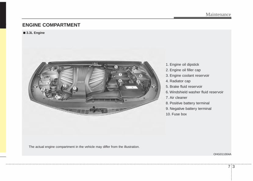
7 3
Maintenance
ENGINE COMPARTMENT
OHG011004A
The actual engine compartment in the vehicle may differ from the illustration.
1. Engine oil dipstick
2. Engine oil filler cap
3. Engine coolant reservoir
4. Radiator cap
5. Brake fluid reservoir
6. Windshield washer fluid reservoir
7. Air cleaner
8. Positive battery terminal
9. Negative battery terminal
10. Fuse box
■■ 3.3L Engine
Maintenance
47
MAINTENANCE SERVICESYou should exercise the utmost careto prevent damage to your vehicleand injury to yourself whenever per-forming any maintenance or inspec-tion procedures.Should you have any doubts con-cerning the inspection or servicing ofyour vehicle, we strongly recom-mend that you have an authorizedKia dealer perform this work.An authorized Kia dealer has factory-trained technicians and genuine Kiaparts to service your vehicle proper-ly. For expert advice and quality serv-ice, see an authorized Kia dealer.Inadequate, incomplete or insuffi-cient servicing may result in opera-tional problems with your vehicle thatcould lead to vehicle damage, anaccident, or personal injury.
Owner’s responsibility
✽✽ NOTICEMaintenance Service and RecordRetention are the owner's responsi-bility. You should retain documents thatshow proper maintenance has beenperformed on your vehicle in accor-dance with the scheduled mainte-nance service charts shown on thefollowing pages. You need this infor-mation to establish your compliancewith the servicing and maintenancerequirements of your vehicle war-ranties.Detailed warranty information isprovided in your Warranty &Consumer Information manual.
Repairs and adjustments required asa result of improper maintenance ora lack of required maintenance arenot covered.We recommend you have your vehi-cle maintained and repaired by anauthorized Kia dealer. An authorizedKia dealer meets Kia’s high servicequality standards and receives tech-nical support from Kia in order to pro-vide you with a high level of servicesatisfaction.
7 5
Maintenance
Owner maintenance precau-tions Improper or incomplete service mayresult in problems. This section givesinstructions only for the maintenanceitems that are easy to perform.As explained earlier in this section,several procedures can be done onlyby an authorized Kia dealer with spe-cial tools.
✽✽ NOTICEImproper owner maintenance dur-ing the warranty period may affectwarranty coverage. For details, readthe separate Warranty & ConsumerInformation manual provided withthe vehicle. If you're unsure aboutany servicing or maintenance proce-dure, have it done by an authorizedKia dealer.
WARNING - Maintenancework
Do not wear jewelry or looseclothing while working underthe hood of your vehicle withthe engine running. These canbecome entangled in movingparts, if you must run theengine while working under thehood, make certain that youremove all jewelry (especiallyrings, bracelets, watches, andnecklaces) and all neckties,scarves, and similar looseclothing before getting near theengine or cooling fans.
Maintenance
67
OWNER MAINTENANCE The following lists are vehicle checksand inspections that should be per-formed by the owner or an author-ized Kia dealer at the frequenciesindicated to help ensure safe,dependable operation of your vehi-cle.Any adverse conditions should bebrought to the attention of your deal-er as soon as possible.These Owner Maintenance Checksare generally not covered by war-ranties and you may be charged forlabor, parts and lubricants used.
Owner maintenance schedule When you stop for fuel:• Check the engine oil level.• Check the coolant level in coolant
reservoir.• Check the windshield washer fluid
level.• Look for low or under-inflated tires.• Check the radiator and condenser.
Check if the front of the radiatorand condenser are clean and notblocked with leaves, dirt or insectsetc. If any of the above parts areextremely dirty or you are not sureof their condition, take your vehicleto an authorized Kia dealer.
While operating your vehicle:• Note any changes in the sound of
the exhaust or any smell ofexhaust fumes in the vehicle.
• Check for vibrations in the steeringwheel. Notice any increased steer-ing effort or looseness in the steer-ing wheel, or change in its straight-ahead position.
• Notice if your vehicle constantlyturns slightly or “pulls” to one sidewhen traveling on smooth, levelroad.
• When stopping, listen and checkfor unusual sounds, pulling to oneside, increased brake pedal travelor “hard-to-push” brake pedal.
• If any slipping or changes in theoperation of your transaxle occurs,check the transaxle fluid level.
• Check the automatic transaxle P(Park) function.
• Check the parking brake.• Check for fluid leaks under your
vehicle (water dripping from the airconditioning system during or afteruse is normal).
WARNING - Hot coolantBe careful when checking yourengine coolant level when theengine is hot. Scalding hotcoolant and steam may blowout under pressure. This couldcause burns or other seriousinjuries.
7 7
Maintenance
At least monthly:• Check the coolant level in the
engine coolant reservoir.• Check the operation of all exterior
lights, including the stoplights, turnsignals and hazard warning flash-ers.
• Check the inflation pressures of alltires including the spare.
At least twice a year (i.e., every Spring and Fall) :• Check the radiator, heater and air
conditioning hoses for leaks ordamage.
• Check the windshield washerspray and wiper operation. Cleanthe wiper blades with clean clothdampened with washer fluid.
• Check the headlight alignment.• Check the muffler, exhaust pipes,
shields and clamps.• Check the lap/shoulder belts for
wear and function.• Check for worn tires and loose
wheel lug nuts.
At least once a year :• Clean the body and door drain
holes.• Lubricate the door hinges and
check the hood hinges.• Lubricate the door and hood locks
and latches.• Lubricate the door rubber weather-
strips.• Check the air conditioning system.• Check the power steering fluid
level.• Inspect and lubricate automatic
transaxle linkage and controls.• Clean the battery and terminals.• Check the brake/clutch fluid level.
Maintenance
87
SCHEDULED MAINTENANCE SERVICE Follow the Normal MaintenanceSchedule if the vehicle is usuallyoperated where none of the followingconditions apply. If any of the followingconditions apply, follow theMaintenance Under Severe UsageConditions.• Repeated short distance driving.• Driving in dusty conditions or
sandy areas.• Extensive use of brakes.• Driving in areas where salt or other
corrosive materials are being used.• Driving on rough or muddy roads.• Driving in mountainous areas.• Extended periods of idling or low
speed operation.• Driving for a prolonged period in
cold temperatures and/or extreme-ly humid climates.
• More than 50% driving in heavycity traffic during hot weatherabove 32°C (90°F).
If your vehicle is operated under theabove conditions, you shouldinspect, replace or refill more fre-quently than the following NormalMaintenance Schedule. After 120months or 240,000 km (150,000miles) continue to follow the pre-scribed maintenance intervals.
7 9
Maintenance
NORMAL MAINTENANCE SCHEDULEThe following maintenance services must be performed to ensure good emission control and performance. Keepreceipts for all vehicle emission services to protect your warranty. Where both mileage and time are shown, the fre-quency of service is determined by whichever occurs first.
*1 : If TOP TIER Detergent Gasoline is not available, one bottle of additive is recommended. Additives are available from yourauthorized Kia dealer along with information on how to use them. Do not mix other additives.
*2 : Fuel filter & Fuel tank air filter are considered to be maintenance free but periodic inspection is recommended for this mainte-nance schedule depends on fuel quality. If there are some important safety matters like fuel flow restriction, surging, loss ofpower, hard starting problem etc, replace the fuel filter immediately regardless of maintenance schedule and consult an author-ized Kia dealer for details.
*3 : The drive belt should be replaced when cracks occur or tension is reduced excessively.*4 : Inspect for excessive tappet noise and/or engine vibration and adjust if necessary.
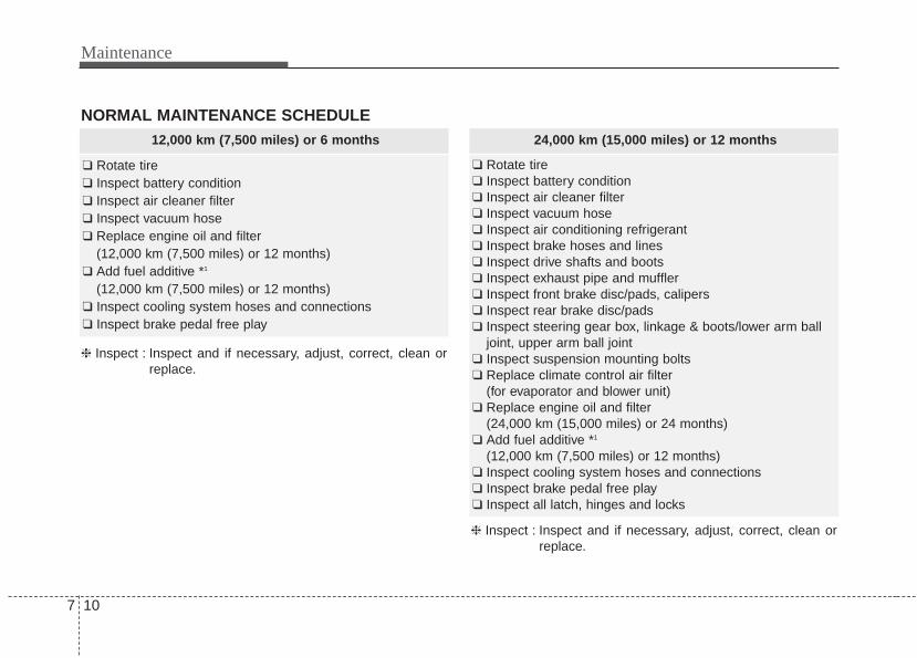
Maintenance
107
NORMAL MAINTENANCE SCHEDULE12,000 km (7,500 miles) or 6 months
❑ Rotate tire❑ Inspect battery condition❑ Inspect air cleaner filter❑ Inspect vacuum hose❑ Replace engine oil and filter
(12,000 km (7,500 miles) or 12 months)❑ Add fuel additive *1
(12,000 km (7,500 miles) or 12 months)❑ Inspect cooling system hoses and connections❑ Inspect brake pedal free play
24,000 km (15,000 miles) or 12 months
❑ Rotate tire❑ Inspect battery condition❑ Inspect air cleaner filter❑ Inspect vacuum hose❑ Inspect air conditioning refrigerant❑ Inspect brake hoses and lines❑ Inspect drive shafts and boots❑ Inspect exhaust pipe and muffler❑ Inspect front brake disc/pads, calipers❑ Inspect rear brake disc/pads❑ Inspect steering gear box, linkage & boots/lower arm ball
joint, upper arm ball joint❑ Inspect suspension mounting bolts❑ Replace climate control air filter
(for evaporator and blower unit)❑ Replace engine oil and filter
(24,000 km (15,000 miles) or 24 months)❑ Add fuel additive *1
(12,000 km (7,500 miles) or 12 months)❑ Inspect cooling system hoses and connections❑ Inspect brake pedal free play❑ Inspect all latch, hinges and locks
❈ Inspect : Inspect and if necessary, adjust, correct, clean orreplace.
❈ Inspect : Inspect and if necessary, adjust, correct, clean orreplace.
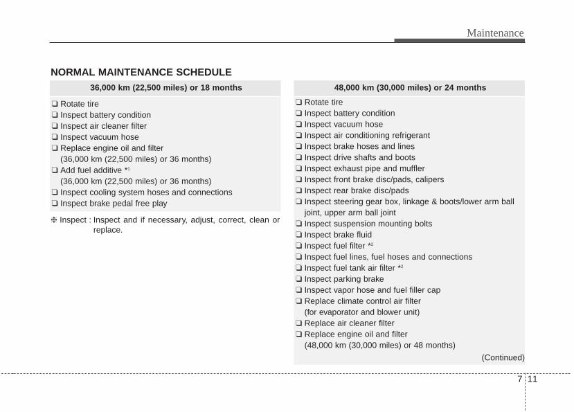
7 11
Maintenance
NORMAL MAINTENANCE SCHEDULE 36,000 km (22,500 miles) or 18 months
❑ Rotate tire❑ Inspect battery condition❑ Inspect air cleaner filter❑ Inspect vacuum hose❑ Replace engine oil and filter
(36,000 km (22,500 miles) or 36 months)❑ Add fuel additive *1
(36,000 km (22,500 miles) or 36 months)❑ Inspect cooling system hoses and connections❑ Inspect brake pedal free play
48,000 km (30,000 miles) or 24 months
❑ Rotate tire❑ Inspect battery condition❑ Inspect vacuum hose❑ Inspect air conditioning refrigerant❑ Inspect brake hoses and lines❑ Inspect drive shafts and boots❑ Inspect exhaust pipe and muffler❑ Inspect front brake disc/pads, calipers❑ Inspect rear brake disc/pads❑ Inspect steering gear box, linkage & boots/lower arm ball
joint, upper arm ball joint❑ Inspect suspension mounting bolts❑ Inspect brake fluid❑ Inspect fuel filter *2
❑ Inspect fuel lines, fuel hoses and connections❑ Inspect fuel tank air filter *2
❑ Inspect parking brake❑ Inspect vapor hose and fuel filler cap❑ Replace climate control air filter
(for evaporator and blower unit)❑ Replace air cleaner filter❑ Replace engine oil and filter
(48,000 km (30,000 miles) or 48 months)
(Continued)
❈ Inspect : Inspect and if necessary, adjust, correct, clean orreplace.
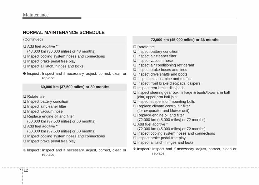
Maintenance
127
72,000 km (45,000 miles) or 36 months
❑ Rotate tire❑ Inspect battery condition❑ Inspect air cleaner filter❑ Inspect vacuum hose❑ Inspect air conditioning refrigerant❑ Inspect brake hoses and lines❑ Inspect drive shafts and boots❑ Inspect exhaust pipe and muffler❑ Inspect front brake disc/pads, calipers❑ Inspect rear brake disc/pads❑ Inspect steering gear box, linkage & boots/lower arm ball
joint, upper arm ball joint❑ Inspect suspension mounting bolts❑ Replace climate control air filter
(for evaporator and blower unit)❑ Replace engine oil and filter
(72,000 km (45,000 miles) or 72 months)❑ Add fuel additive *1
(72,000 km (45,000 miles) or 72 months)❑ Inspect cooling system hoses and connections❑ Inspect brake pedal free play❑ Inspect all latch, hinges and locks
❈ Inspect : Inspect and if necessary, adjust, correct, clean orreplace.
60,000 km (37,500 miles) or 30 months
❑ Rotate tire❑ Inspect battery condition❑ Inspect air cleaner filter❑ Inspect vacuum hose❑ Replace engine oil and filter
(60,000 km (37,500 miles) or 60 months)❑ Add fuel additive *1
(60,000 km (37,500 miles) or 60 months)❑ Inspect cooling system hoses and connections❑ Inspect brake pedal free play
NORMAL MAINTENANCE SCHEDULE(Continued)
❑ Add fuel additive *1
(48,000 km (30,000 miles) or 48 months)❑ Inspect cooling system hoses and connections❑ Inspect brake pedal free play❑ Inspect all latch, hinges and locks
❈ Inspect : Inspect and if necessary, adjust, correct, clean orreplace.
❈ Inspect : Inspect and if necessary, adjust, correct, clean orreplace.
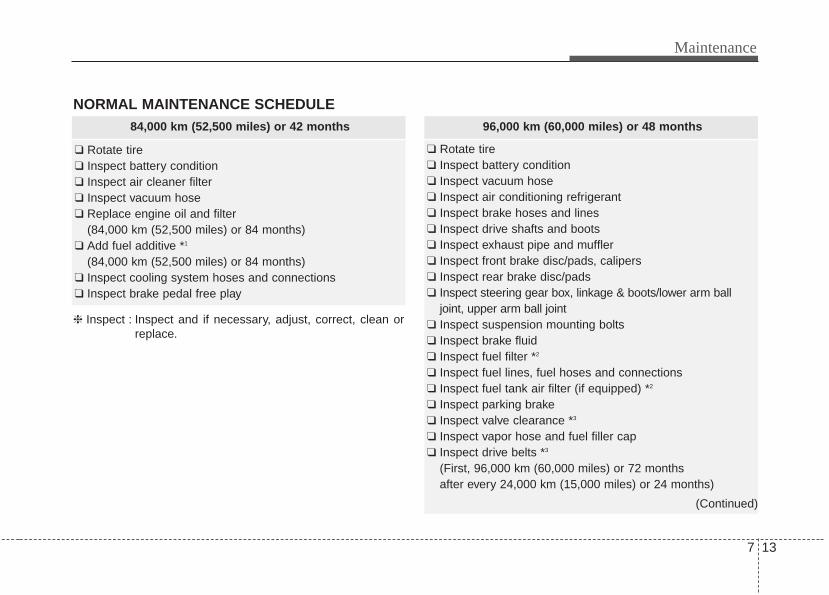
7 13
Maintenance
NORMAL MAINTENANCE SCHEDULE84,000 km (52,500 miles) or 42 months
❑ Rotate tire❑ Inspect battery condition❑ Inspect air cleaner filter❑ Inspect vacuum hose❑ Replace engine oil and filter
(84,000 km (52,500 miles) or 84 months)❑ Add fuel additive *1
(84,000 km (52,500 miles) or 84 months)❑ Inspect cooling system hoses and connections❑ Inspect brake pedal free play
❈ Inspect : Inspect and if necessary, adjust, correct, clean orreplace.
96,000 km (60,000 miles) or 48 months
❑ Rotate tire❑ Inspect battery condition❑ Inspect vacuum hose❑ Inspect air conditioning refrigerant❑ Inspect brake hoses and lines❑ Inspect drive shafts and boots❑ Inspect exhaust pipe and muffler❑ Inspect front brake disc/pads, calipers❑ Inspect rear brake disc/pads❑ Inspect steering gear box, linkage & boots/lower arm ball
joint, upper arm ball joint❑ Inspect suspension mounting bolts❑ Inspect brake fluid❑ Inspect fuel filter *2
❑ Inspect fuel lines, fuel hoses and connections❑ Inspect fuel tank air filter (if equipped) *2
❑ Inspect parking brake❑ Inspect valve clearance *3
❑ Inspect vapor hose and fuel filler cap❑ Inspect drive belts *3
(First, 96,000 km (60,000 miles) or 72 monthsafter every 24,000 km (15,000 miles) or 24 months)
(Continued)
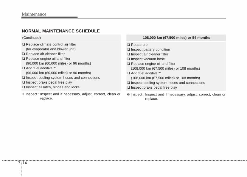
Maintenance
147
108,000 km (67,500 miles) or 54 months
❑ Rotate tire❑ Inspect battery condition❑ Inspect air cleaner filter❑ Inspect vacuum hose❑ Replace engine oil and filter
(108,000 km (67,500 miles) or 108 months)❑ Add fuel additive *1
(108,000 km (67,500 miles) or 108 months)❑ Inspect cooling system hoses and connections❑ Inspect brake pedal free play
❈ Inspect : Inspect and if necessary, adjust, correct, clean orreplace.
NORMAL MAINTENANCE SCHEDULE (Continued)
❑ Replace climate control air filter (for evaporator and blower unit)
❑ Replace air cleaner filter❑ Replace engine oil and filter
(96,000 km (60,000 miles) or 96 months)❑ Add fuel additive *1
(96,000 km (60,000 miles) or 96 months)❑ Inspect cooling system hoses and connections❑ Inspect brake pedal free play❑ Inspect all latch, hinges and locks
❈ Inspect : Inspect and if necessary, adjust, correct, clean orreplace.
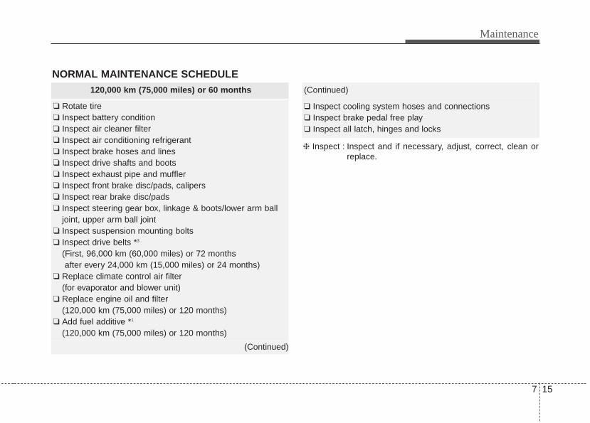
7 15
Maintenance
NORMAL MAINTENANCE SCHEDULE 120,000 km (75,000 miles) or 60 months
❑ Rotate tire❑ Inspect battery condition❑ Inspect air cleaner filter❑ Inspect air conditioning refrigerant❑ Inspect brake hoses and lines❑ Inspect drive shafts and boots❑ Inspect exhaust pipe and muffler❑ Inspect front brake disc/pads, calipers❑ Inspect rear brake disc/pads❑ Inspect steering gear box, linkage & boots/lower arm ball
joint, upper arm ball joint❑ Inspect suspension mounting bolts❑ Inspect drive belts *3
(First, 96,000 km (60,000 miles) or 72 months after every 24,000 km (15,000 miles) or 24 months)
❑ Replace climate control air filter (for evaporator and blower unit)
❑ Replace engine oil and filter (120,000 km (75,000 miles) or 120 months)
❑ Add fuel additive *1
(120,000 km (75,000 miles) or 120 months)
(Continued)
(Continued)
❑ Inspect cooling system hoses and connections❑ Inspect brake pedal free play❑ Inspect all latch, hinges and locks
❈ Inspect : Inspect and if necessary, adjust, correct, clean orreplace.
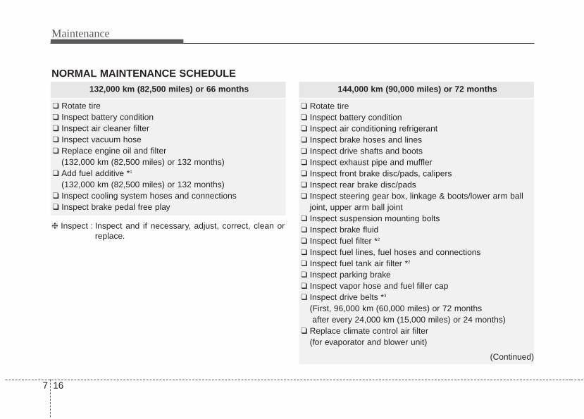
Maintenance
167
144,000 km (90,000 miles) or 72 months
❑ Rotate tire❑ Inspect battery condition❑ Inspect air conditioning refrigerant❑ Inspect brake hoses and lines❑ Inspect drive shafts and boots❑ Inspect exhaust pipe and muffler❑ Inspect front brake disc/pads, calipers❑ Inspect rear brake disc/pads❑ Inspect steering gear box, linkage & boots/lower arm ball
joint, upper arm ball joint❑ Inspect suspension mounting bolts❑ Inspect brake fluid❑ Inspect fuel filter *2
❑ Inspect fuel lines, fuel hoses and connections❑ Inspect fuel tank air filter *2
❑ Inspect parking brake❑ Inspect vapor hose and fuel filler cap❑ Inspect drive belts *3
(First, 96,000 km (60,000 miles) or 72 months after every 24,000 km (15,000 miles) or 24 months)
❑ Replace climate control air filter (for evaporator and blower unit)
(Continued)
NORMAL MAINTENANCE SCHEDULE132,000 km (82,500 miles) or 66 months
❑ Rotate tire❑ Inspect battery condition❑ Inspect air cleaner filter❑ Inspect vacuum hose❑ Replace engine oil and filter
(132,000 km (82,500 miles) or 132 months)❑ Add fuel additive *1
(132,000 km (82,500 miles) or 132 months)❑ Inspect cooling system hoses and connections❑ Inspect brake pedal free play
❈ Inspect : Inspect and if necessary, adjust, correct, clean orreplace.
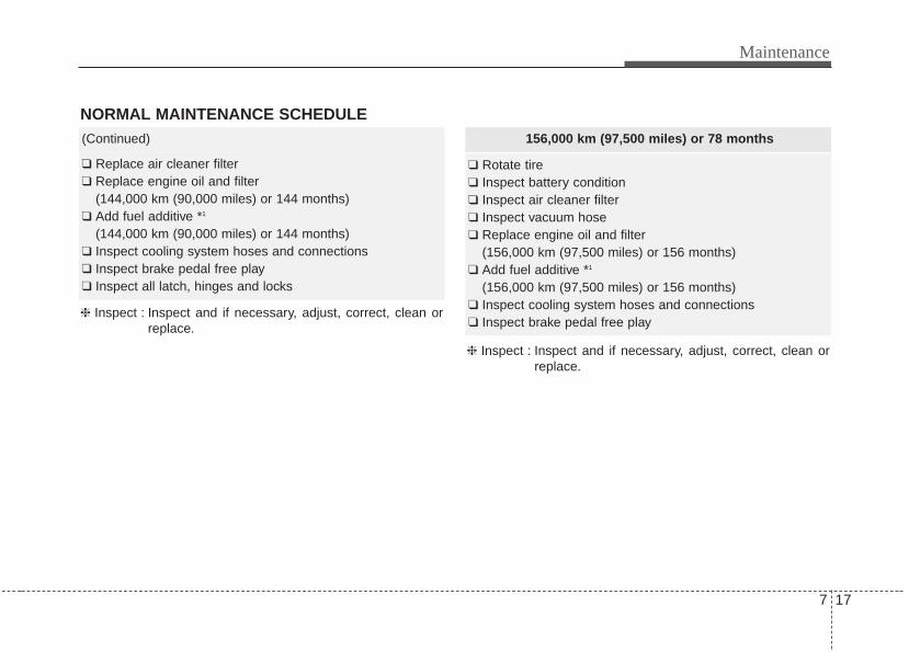
7 17
Maintenance
NORMAL MAINTENANCE SCHEDULE(Continued)
❑ Replace air cleaner filter❑ Replace engine oil and filter
(144,000 km (90,000 miles) or 144 months)❑ Add fuel additive *1
(144,000 km (90,000 miles) or 144 months)❑ Inspect cooling system hoses and connections❑ Inspect brake pedal free play❑ Inspect all latch, hinges and locks
❈ Inspect : Inspect and if necessary, adjust, correct, clean orreplace.
156,000 km (97,500 miles) or 78 months
❑ Rotate tire❑ Inspect battery condition❑ Inspect air cleaner filter❑ Inspect vacuum hose❑ Replace engine oil and filter
(156,000 km (97,500 miles) or 156 months)❑ Add fuel additive *1
(156,000 km (97,500 miles) or 156 months)❑ Inspect cooling system hoses and connections❑ Inspect brake pedal free play
❈ Inspect : Inspect and if necessary, adjust, correct, clean orreplace.
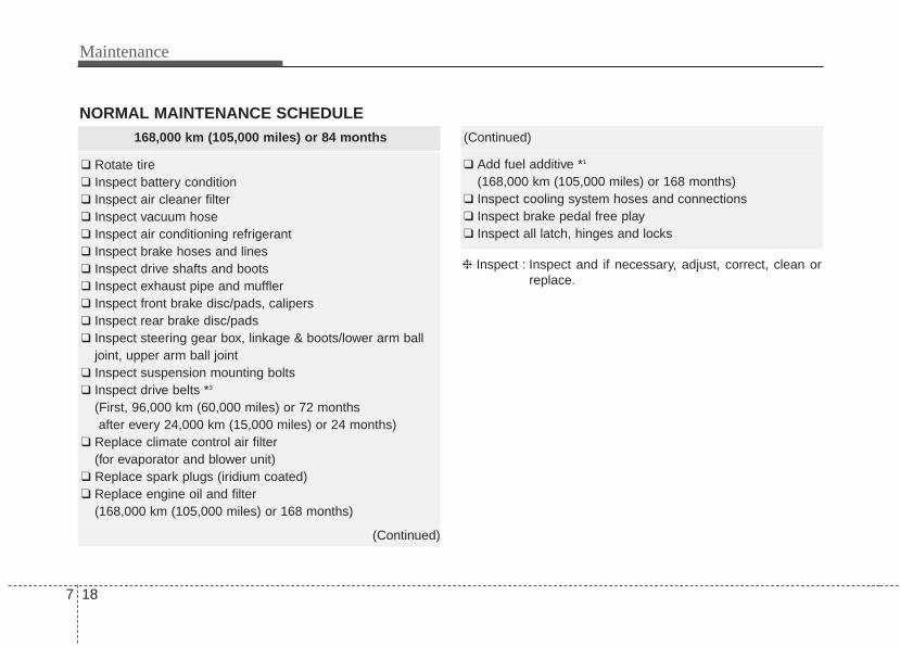
Maintenance
187
(Continued)
❑ Add fuel additive *1
(168,000 km (105,000 miles) or 168 months)❑ Inspect cooling system hoses and connections❑ Inspect brake pedal free play❑ Inspect all latch, hinges and locks
❈ Inspect : Inspect and if necessary, adjust, correct, clean orreplace.
168,000 km (105,000 miles) or 84 months
❑ Rotate tire❑ Inspect battery condition❑ Inspect air cleaner filter❑ Inspect vacuum hose❑ Inspect air conditioning refrigerant❑ Inspect brake hoses and lines❑ Inspect drive shafts and boots❑ Inspect exhaust pipe and muffler❑ Inspect front brake disc/pads, calipers❑ Inspect rear brake disc/pads❑ Inspect steering gear box, linkage & boots/lower arm ball
joint, upper arm ball joint❑ Inspect suspension mounting bolts❑ Inspect drive belts *3
(First, 96,000 km (60,000 miles) or 72 months after every 24,000 km (15,000 miles) or 24 months)
❑ Replace climate control air filter (for evaporator and blower unit)
❑ Replace spark plugs (iridium coated) ❑ Replace engine oil and filter
(168,000 km (105,000 miles) or 168 months)
(Continued)
NORMAL MAINTENANCE SCHEDULE
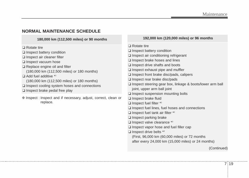
7 19
Maintenance
NORMAL MAINTENANCE SCHEDULE
❈ Inspect : Inspect and if necessary, adjust, correct, clean orreplace.
180,000 km (112,500 miles) or 90 months
❑ Rotate tire❑ Inspect battery condition❑ Inspect air cleaner filter❑ Inspect vacuum hose❑ Replace engine oil and filter
(180,000 km (112,500 miles) or 180 months)❑ Add fuel additive *1
(180,000 km (112,500 miles) or 180 months)❑ Inspect cooling system hoses and connections❑ Inspect brake pedal free play
192,000 km (120,000 miles) or 96 months
❑ Rotate tire❑ Inspect battery condition❑ Inspect air conditioning refrigerant❑ Inspect brake hoses and lines❑ Inspect drive shafts and boots❑ Inspect exhaust pipe and muffler❑ Inspect front brake disc/pads, calipers❑ Inspect rear brake disc/pads❑ Inspect steering gear box, linkage & boots/lower arm ball
joint, upper arm ball joint❑ Inspect suspension mounting bolts❑ Inspect brake fluid❑ Inspect fuel filter *2
❑ Inspect fuel lines, fuel hoses and connections❑ Inspect fuel tank air filter *2
❑ Inspect parking brake❑ Inspect valve clearance *3
❑ Inspect vapor hose and fuel filler cap❑ Inspect drive belts *3
(First, 96,000 km (60,000 miles) or 72 months after every 24,000 km (15,000 miles) or 24 months)
(Continued)
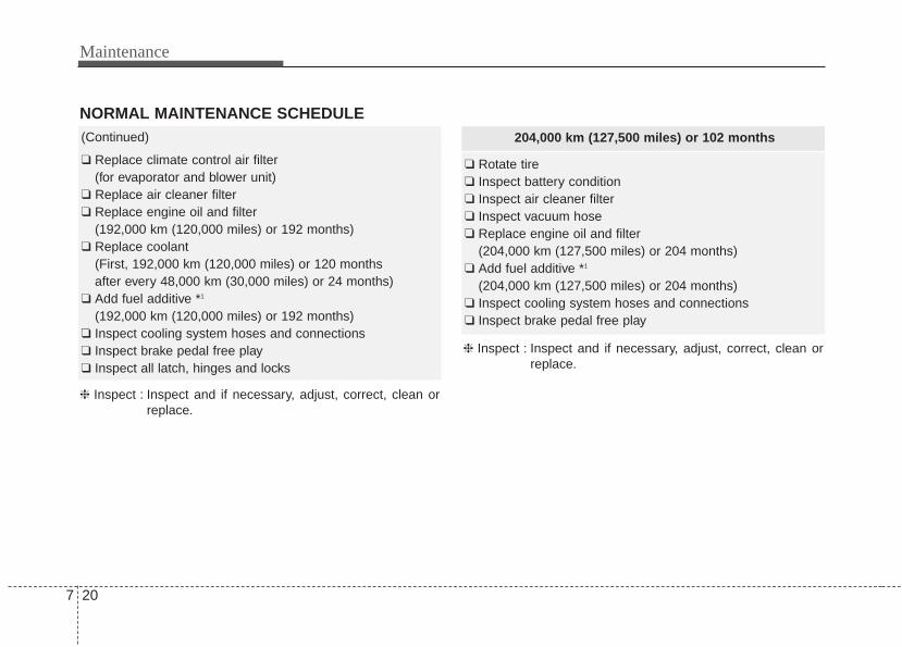
Maintenance
207
204,000 km (127,500 miles) or 102 months
❑ Rotate tire❑ Inspect battery condition❑ Inspect air cleaner filter❑ Inspect vacuum hose❑ Replace engine oil and filter
(204,000 km (127,500 miles) or 204 months)❑ Add fuel additive *1
(204,000 km (127,500 miles) or 204 months)❑ Inspect cooling system hoses and connections❑ Inspect brake pedal free play
❈ Inspect : Inspect and if necessary, adjust, correct, clean orreplace.
(Continued)
❑ Replace climate control air filter(for evaporator and blower unit)
❑ Replace air cleaner filter❑ Replace engine oil and filter
(192,000 km (120,000 miles) or 192 months)❑ Replace coolant
(First, 192,000 km (120,000 miles) or 120 months after every 48,000 km (30,000 miles) or 24 months)
❑ Add fuel additive *1
(192,000 km (120,000 miles) or 192 months)❑ Inspect cooling system hoses and connections❑ Inspect brake pedal free play❑ Inspect all latch, hinges and locks
NORMAL MAINTENANCE SCHEDULE
❈ Inspect : Inspect and if necessary, adjust, correct, clean orreplace.
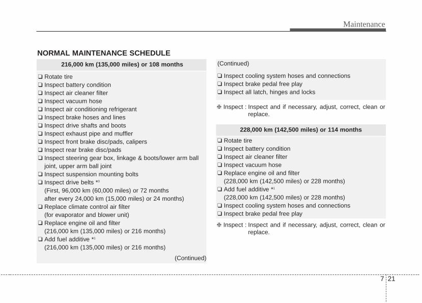
7 21
Maintenance
NORMAL MAINTENANCE SCHEDULE216,000 km (135,000 miles) or 108 months
❑ Rotate tire❑ Inspect battery condition❑ Inspect air cleaner filter❑ Inspect vacuum hose❑ Inspect air conditioning refrigerant❑ Inspect brake hoses and lines❑ Inspect drive shafts and boots❑ Inspect exhaust pipe and muffler❑ Inspect front brake disc/pads, calipers❑ Inspect rear brake disc/pads❑ Inspect steering gear box, linkage & boots/lower arm ball
joint, upper arm ball joint❑ Inspect suspension mounting bolts❑ Inspect drive belts *3
(First, 96,000 km (60,000 miles) or 72 months after every 24,000 km (15,000 miles) or 24 months)
❑ Replace climate control air filter (for evaporator and blower unit)
❑ Replace engine oil and filter(216,000 km (135,000 miles) or 216 months)
❑ Add fuel additive *1
(216,000 km (135,000 miles) or 216 months)
(Continued)
(Continued)
❑ Inspect cooling system hoses and connections❑ Inspect brake pedal free play❑ Inspect all latch, hinges and locks
❈ Inspect : Inspect and if necessary, adjust, correct, clean orreplace.
228,000 km (142,500 miles) or 114 months
❑ Rotate tire❑ Inspect battery condition❑ Inspect air cleaner filter❑ Inspect vacuum hose❑ Replace engine oil and filter
(228,000 km (142,500 miles) or 228 months)❑ Add fuel additive *1
(228,000 km (142,500 miles) or 228 months)❑ Inspect cooling system hoses and connections❑ Inspect brake pedal free play
❈ Inspect : Inspect and if necessary, adjust, correct, clean orreplace.
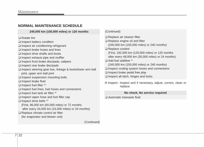
Maintenance
227
No check, No service required
❑ Automatic transaxle fluid
240,000 km (150,000 miles) or 120 months
❑ Rotate tire❑ Inspect battery condition❑ Inspect air conditioning refrigerant❑ Inspect brake hoses and lines❑ Inspect drive shafts and boots❑ Inspect exhaust pipe and muffler❑ Inspect front brake disc/pads, calipers❑ Inspect rear brake disc/pads❑ Inspect steering gear box, linkage & boots/lower arm ball
joint, upper arm ball joint❑ Inspect suspension mounting bolts❑ Inspect brake fluid❑ Inspect fuel filter *2
❑ Inspect fuel lines, fuel hoses and connections❑ Inspect fuel tank air filter *2
❑ Inspect vapor hose and fuel filler cap❑ Inspect drive belts *3
(First, 96,000 km (60,000 miles) or 72 months after every 24,000 km (15,000 miles) or 24 months)
❑ Replace climate control air filter (for evaporator and blower unit)
(Continued)
(Continued)
❑ Replace air cleaner filter❑ Replace engine oil and filter
(240,000 km (150,000 miles) or 240 months)❑ Replace coolant
(First, 192,000 km (120,000 miles) or 120 months after every 48,000 km (30,000 miles) or 24 months)
❑ Add fuel additive *1
(240,000 km (150,000 miles) or 240 months)❑ Inspect cooling system hoses and connections❑ Inspect brake pedal free play❑ Inspect all latch, hinges and locks
❈ Inspect : Inspect and if necessary, adjust, correct, clean orreplace.
NORMAL MAINTENANCE SCHEDULE
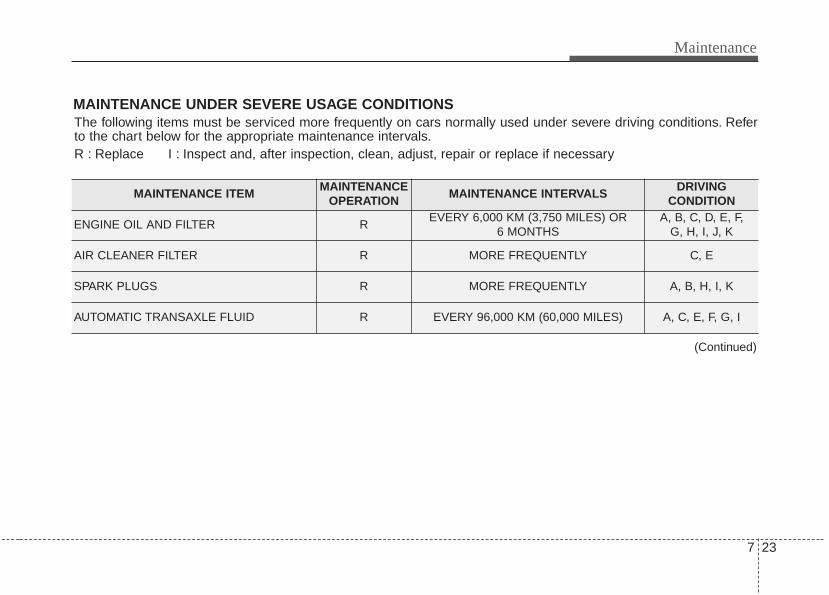
7 23
Maintenance
MAINTENANCE UNDER SEVERE USAGE CONDITIONSThe following items must be serviced more frequently on cars normally used under severe driving conditions. Referto the chart below for the appropriate maintenance intervals.R : Replace I : Inspect and, after inspection, clean, adjust, repair or replace if necessary
MAINTENANCE ITEMMAINTENANCE
OPERATIONMAINTENANCE INTERVALS
DRIVING CONDITION
ENGINE OIL AND FILTER REVERY 6,000 KM (3,750 MILES) OR
6 MONTHSA, B, C, D, E, F,
G, H, I, J, K
AIR CLEANER FILTER R MORE FREQUENTLY C, E
SPARK PLUGS R MORE FREQUENTLY A, B, H, I, K
AUTOMATIC TRANSAXLE FLUID R EVERY 96,000 KM (60,000 MILES) A, C, E, F, G, I
(Continued)
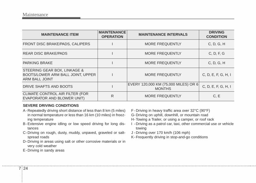
Maintenance
247
SEVERE DRIVING CONDITIONSA-Repeatedly driving short distance of less than 8 km (5 miles)
in normal temperature or less than 16 km (10 miles) in freez-ing temperature
B-Extensive engine idling or low speed driving for long dis-tances
C-Driving on rough, dusty, muddy, unpaved, graveled or salt-spread roads
D-Driving in areas using salt or other corrosive materials or invery cold weather
E-Driving in sandy areas
F -Driving in heavy traffic area over 32°C (90°F)G-Driving on uphill, downhill, or mountain roadH-Towing a Trailer, or using a camper, or roof rackI -Driving as a patrol car, taxi, other commercial use or vehicle
towingJ -Driving over 170 km/h (106 mph)K-Frequently driving in stop-and-go conditions
MAINTENANCE ITEMMAINTENANCE
OPERATIONMAINTENANCE INTERVALS
DRIVING CONDITION
FRONT DISC BRAKE/PADS, CALIPERS I MORE FREQUENTLY C, D, G, H
REAR DISC BRAKE/PADS I MORE FREQUENTLY C, D, F, G
PARKING BRAKE I MORE FREQUENTLY C, D, G, H
STEERING GEAR BOX, LINKAGE &BOOTS/LOWER ARM BALL JOINT, UPPERARM BALL JOINT
I MORE FREQUENTLY C, D, E, F, G, H, I
DRIVE SHAFTS AND BOOTS IEVERY 120,000 KM (75,000 MILES) OR 6
MONTHSC, D, E, F, G, H, I
CLIMATE CONTROL AIR FILTER (FOREVAPORATOR AND BLOWER UNIT)
R MORE FREQUENTLY C, E
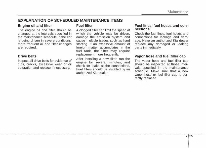
7 25
Maintenance
EXPLANATION OF SCHEDULED MAINTENANCE ITEMSEngine oil and filterThe engine oil and filter should bechanged at the intervals specified inthe maintenance schedule. If the caris being driven in severe conditions,more frequent oil and filter changesare required.
Drive beltsInspect all drive belts for evidence ofcuts, cracks, excessive wear or oilsaturation and replace if necessary.
Fuel filterA clogged filter can limit the speed atwhich the vehicle may be driven,damage the emission system andcause multiple issues such as hardstarting. If an excessive amount offoreign matter accumulates in thefuel tank, the filter may requirereplacement more frequently.After installing a new filter, run theengine for several minutes, andcheck for leaks at the connections.Fuel filters should be installed by anauthorized Kia dealer.
Fuel lines, fuel hoses and con-nectionsCheck the fuel lines, fuel hoses andconnections for leakage and dam-age. Have an authorized Kia dealerreplace any damaged or leakingparts immediately.
Vapor hose and fuel filler capThe vapor hose and fuel filler capshould be inspected at those inter-vals specified in the maintenanceschedule. Make sure that a newvapor hose or fuel filler cap is cor-rectly replaced.
Maintenance
267
Vacuum crankcase ventilationhosesInspect the surface of hoses for evi-dence of heat and/or mechanicaldamage. Hard and brittle rubber,cracking, tears, cuts, abrasions, andexcessive swelling indicate deterio-ration. Particular attention should bepaid to examine those hose surfacesnearest to high heat sources, suchas the exhaust manifold.Inspect the hose routing to assurethat the hoses do not come in con-tact with any heat source, sharpedges or moving component whichmight cause heat damage ormechanical wear. Inspect all hoseconnections, such as clamps andcouplings, to make sure they aresecure, and that no leaks are pres-ent. Hoses should be replacedimmediately if there is any evidenceof deterioration or damage.
Air cleaner filterA Genuine Kia air cleaner filter isrecommended when the filter isreplaced.
Spark plugsMake sure to install new spark plugsof the correct heat range.
Valve clearanceInspect excessive valve noise and/orengine vibration and adjust if neces-sary. An authorized Kia dealershould perform the operation.
Cooling systemCheck cooling system components,such as radiator, coolant reservoir,hoses and connections for leakageand damage. Replace any damagedparts.
CoolantThe coolant should be changed atthe intervals specified in the mainte-nance schedule.
7 27
Maintenance
Automatic transaxle fluid Automatic transaxle fluid does notneed to be checked under normalusage conditions.But in severe conditions, the fluidshould be changed at an authorizedKia dealer in accordance to thescheduled maintenance at the begin-ning of this chapter.
✽✽ NOTICEAutomatic transaxle fluid color isbasically red. As the vehicle is driven, the auto-matic transaxle fluid will begin tolook darker.This a normal condition and youshould not judge the need to replacethe fluid based upon the changedcolor.
The use of a non-specified fluidcould result in transaxle malfunctionand failure.Use only specified automatictransaxle fluid. (Refer to“Recommended lubricants andcapacities” in section 8.)
Brake hoses and linesVisually check for proper installation,chafing, cracks, deterioration andany leakage. Replace any deteriorat-ed or damaged parts immediately.
Brake fluidCheck brake fluid level in the brakefluid reservoir. The level should bebetween “MIN” and “MAX” marks onthe side of the reservoir. Use onlyhydraulic brake fluid conforming toDOT 3 or DOT 4 specification.
Parking brakeInspect the parking brake systemincluding the parking brake pedal orlever and cables.
Brake discs, pads, calipersand rotorsCheck the pads for excessive wear,discs for run out and wear, andcalipers for fluid leakage.
Suspension mounting boltsCheck the suspension connectionsfor looseness or damage. Retightento the specified torque.
Steering gear box, linkage &boots/lower arm ball jointWith the vehicle stopped and engineoff, check for excessive free-play inthe steering wheel.Check the linkage for bends or dam-age. Check the dust boots and balljoints for deterioration, cracks, ordamage. Replace any damagedparts.
Maintenance
287
Exhaust pipe and mufflerVisually inspect the exhaust pipes,muffler and hangers for cracks, dete-rioration, or damage. Start theengine and listen carefully for anyexhaust gas leakage. Tighten con-nections or replace parts as neces-sary.
Drive shafts and bootsCheck the drive shafts, boots andclamps for cracks, deterioration, ordamage. Replace any damagedparts and, if necessary, repack thegrease.
Air conditioning refrigerantCheck the air conditioning lines andconnections for leakage and dam-age.
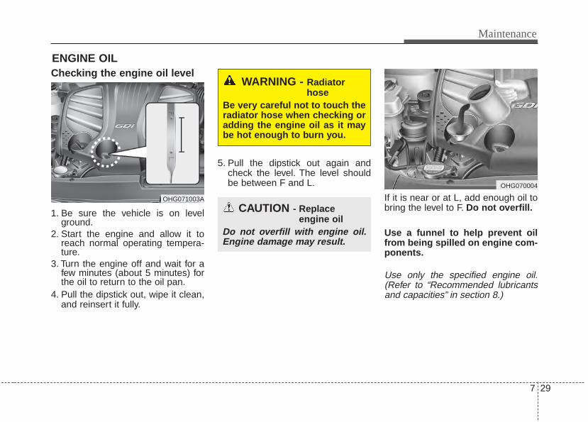
7 29
Maintenance
ENGINE OILChecking the engine oil level
1. Be sure the vehicle is on levelground.
2. Start the engine and allow it toreach normal operating tempera-ture.
3. Turn the engine off and wait for afew minutes (about 5 minutes) forthe oil to return to the oil pan.
4. Pull the dipstick out, wipe it clean,and reinsert it fully.
5. Pull the dipstick out again andcheck the level. The level shouldbe between F and L.
If it is near or at L, add enough oil tobring the level to F. Do not overfill.
Use a funnel to help prevent oilfrom being spilled on engine com-ponents.
Use only the specified engine oil.(Refer to “Recommended lubricantsand capacities” in section 8.)
WARNING - Radiatorhose
Be very careful not to touch theradiator hose when checking oradding the engine oil as it maybe hot enough to burn you.
CAUTION - Replaceengine oil
Do not overfill with engine oil.Engine damage may result.
OHG071003A
OHG070004
Maintenance
307
Changing the engine oil andfilterHave engine oil and filter changed byan authorized Kia dealer accordingto the Maintenance Schedule at thebeginning of this chapter.
WARNINGUsed engine oil may cause irri-tation or cancer of the skin ifleft in contact with the skin forprolonged periods of time.Always protect your skin bywashing your hands thoroughlywith soap and warm water assoon as possible after handlingused oil.

7 31
Maintenance
ENGINE COOLANTThe high-pressure cooling systemhas a reservoir filled with year-roundantifreeze coolant. The reservoir isfilled at the factory.Check the antifreeze protection andcoolant level at least once a year, atthe beginning of the winter season,and before traveling to a colder cli-mate.
Checking the coolant level
Check the condition and connectionsof all cooling system hoses andheater hoses. Replace any swollenor deteriorated hoses.The coolant level should be filledbetween F (MAX) and L (MIN) markson the side of the coolant reservoirwhen the engine is cool.
If the coolant level is low, add enoughdistilled (deionized) water. Bring thelevel to F (MAX), but do not overfill. Iffrequent coolant addition is required,see an authorized Kia dealer for acooling system inspection.
WARNING - Cooling fanUse caution whenworking near theblade of the coolingfan. The electricmotor (cooling fan) is
controlled by engine coolanttemperature, refrigerant pres-sure and vehicle speed. It maysometimes operate even whenthe engine is not running.Your vehicle equipped with GDI,the electric motor (cooling fan)may operate until you discon-nect the negative battery cable.Not heeding these warningscould result in serious injuries.
OHG070005
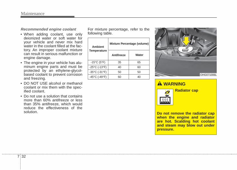
Maintenance
327
WARNING Radiator cap
Do not remove the radiator capwhen the engine and radiatorare hot. Scalding hot coolantand steam may blow out underpressure.
Recommended engine coolant• When adding coolant, use only
deionized water or soft water foryour vehicle and never mix hardwater in the coolant filled at the fac-tory. An improper coolant mixturecan result in serious malfunction orengine damage.
• The engine in your vehicle has alu-minum engine parts and must beprotected by an ethylene-glycol-based coolant to prevent corrosionand freezing.
• DO NOT USE alcohol or methanolcoolant or mix them with the spec-ified coolant.
• Do not use a solution that containsmore than 60% antifreeze or lessthan 35% antifreeze, which wouldreduce the effectiveness of thesolution.
For mixture percentage, refer to thefollowing table.
-15°C (5°F) 35 65
-25°C (-13°F) 40 60
-35°C (-31°F) 50 50
-45°C (-49°F) 60 40
AmbientTemperature
Mixture Percentage (volume)
Antifreeze Water
OHG071006L
7 33
Maintenance
Turn the engine off and wait until itcools down. Use care when remov-ing the radiator cap. Wrap a thicktowel around it, and turn it counter-clockwise slowly to the first stop.Step back while the pressure isreleased from the cooling system.When you are sure all the pressurehas been released, press down onthe cap, using a thick towel, and con-tinue turning counterclockwise toremove it.
Changing the coolantHave the coolant changed by anauthorized Kia dealer according tothe Maintenance Schedule at thebeginning of this section.Put a thick cloth or fabric around theradiator cap before refilling thecoolant in order to prevent thecoolant from overflowing into engineparts such as the alternator.
CAUTION - Removingradiator cap
Never attempt toremove the radiatorcap while the engineis operating or hot.Doing so might leadto cooling system andengine damage.
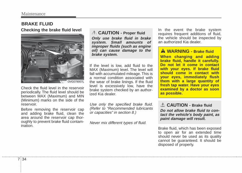
Maintenance
347
BRAKE FLUIDChecking the brake fluid level
Check the fluid level in the reservoirperiodically. The fluid level should bebetween MAX (Maximum) and MIN(Minimum) marks on the side of thereservoir.Before removing the reservoir capand adding brake fluid, clean thearea around the reservoir cap thor-oughly to prevent brake fluid contam-ination.
If the level is low, add fluid to theMAX (Maximum) level. The level willfall with accumulated mileage. This isa normal condition associated withthe wear of brake linings. If the fluidlevel is excessively low, have thebrake system checked by an author-ized Kia dealer.
Use only the specified brake fluid.(Refer to “Recommended lubricantsor capacities” in section 8.)
Never mix different types of fluid.
In the event the brake systemrequires frequent additions of fluid,the vehicle should be inspected byan authorized Kia dealer.
Brake fluid, which has been exposedto open air for an extended timeshould never be used as its qualitycannot be guaranteed. It should bedisposed of properly.
OVG079007L
CAUTION - Proper fluidOnly use brake fluid in brakesystem. Small amounts ofimproper fluids (such as engineoil) can cause damage to thebrake system.
CAUTION - Brake fluidDo not allow brake fluid to con-tact the vehicle's body paint, aspaint damage will result.
WARNING - Brake fluidWhen changing and addingbrake fluid, handle it carefully.Do not let it come in contactwith your eyes. If brake fluidshould come in contact withyour eyes, immediately flushthem with a large quantity offresh tap water. Have your eyesexamined by a doctor as soonas possible.
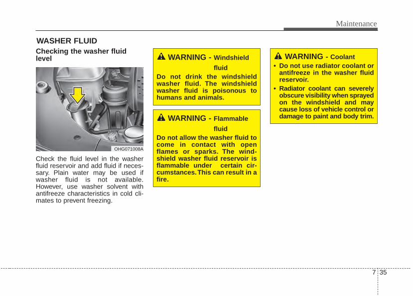
7 35
Maintenance
WASHER FLUIDChecking the washer fluidlevel
Check the fluid level in the washerfluid reservoir and add fluid if neces-sary. Plain water may be used ifwasher fluid is not available.However, use washer solvent withantifreeze characteristics in cold cli-mates to prevent freezing.
WARNING - Windshield
fluidDo not drink the windshieldwasher fluid. The windshieldwasher fluid is poisonous tohumans and animals.
WARNING - Flammable
fluidDo not allow the washer fluid tocome in contact with openflames or sparks. The wind-shield washer fluid reservoir isflammable under certain cir-cumstances.This can result in afire.
OHG071008A
WARNING - Coolant• Do not use radiator coolant or
antifreeze in the washer fluidreservoir.
• Radiator coolant can severelyobscure visibility when sprayedon the windshield and maycause loss of vehicle control ordamage to paint and body trim.
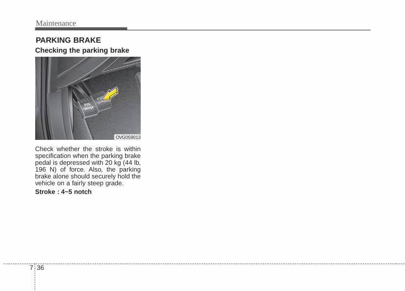
Maintenance
367
PARKING BRAKEChecking the parking brake
Check whether the stroke is withinspecification when the parking brakepedal is depressed with 20 kg (44 lb,196 N) of force. Also, the parkingbrake alone should securely hold thevehicle on a fairly steep grade.Stroke : 4~5 notch
OVG059013
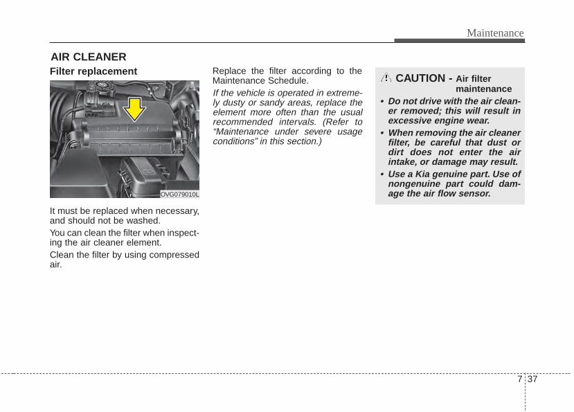
7 37
Maintenance
Filter replacement
It must be replaced when necessary,and should not be washed.You can clean the filter when inspect-ing the air cleaner element.Clean the filter by using compressedair.
Replace the filter according to theMaintenance Schedule.If the vehicle is operated in extreme-ly dusty or sandy areas, replace theelement more often than the usualrecommended intervals. (Refer to“Maintenance under severe usageconditions” in this section.)
AIR CLEANER
OVG079010L
CAUTION - Air filter maintenance
• Do not drive with the air clean-er removed; this will result inexcessive engine wear.
• When removing the air cleanerfilter, be careful that dust ordirt does not enter the airintake, or damage may result.
• Use a Kia genuine part. Use ofnongenuine part could dam-age the air flow sensor.
Maintenance
387
CLIMATE CONTROL AIR FILTER (IF EQUIPPED)Filter inspectionThe climate control air filter shouldbe replaced according to theMaintenance Schedule. If the vehicleis operated in severely air-pollutedcities or on dusty rough roads for along period, it should be inspectedmore frequently and replaced earlier.When you replace the climate controlair filter, replace it performing the fol-lowing procedure, and be careful toavoid damaging other components.
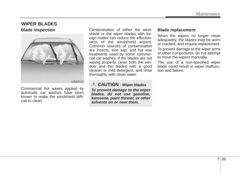
7 39
Maintenance
WIPER BLADESBlade inspection
Commercial hot waxes applied byautomatic car washes have beenknown to make the windshield diffi-cult to clean.
Contamination of either the wind-shield or the wiper blades with for-eign matter can reduce the effective-ness of the windshield wipers.Common sources of contaminationare insects, tree sap, and hot waxtreatments used by some commer-cial car washes. If the blades are notwiping properly, clean both the win-dow and the blades with a goodcleaner or mild detergent, and rinsethoroughly with clean water.
Blade replacement When the wipers no longer cleanadequately, the blades may be wornor cracked, and require replacement.To prevent damage to the wiper armsor other components, do not attemptto move the wipers manually.The use of a non-specified wiperblade could result in wiper malfunc-tion and failure.
1JBA5122CAUTION - Wiper blades
To prevent damage to the wiperblades, do not use gasoline,kerosene, paint thinner, or othersolvents on or near them.
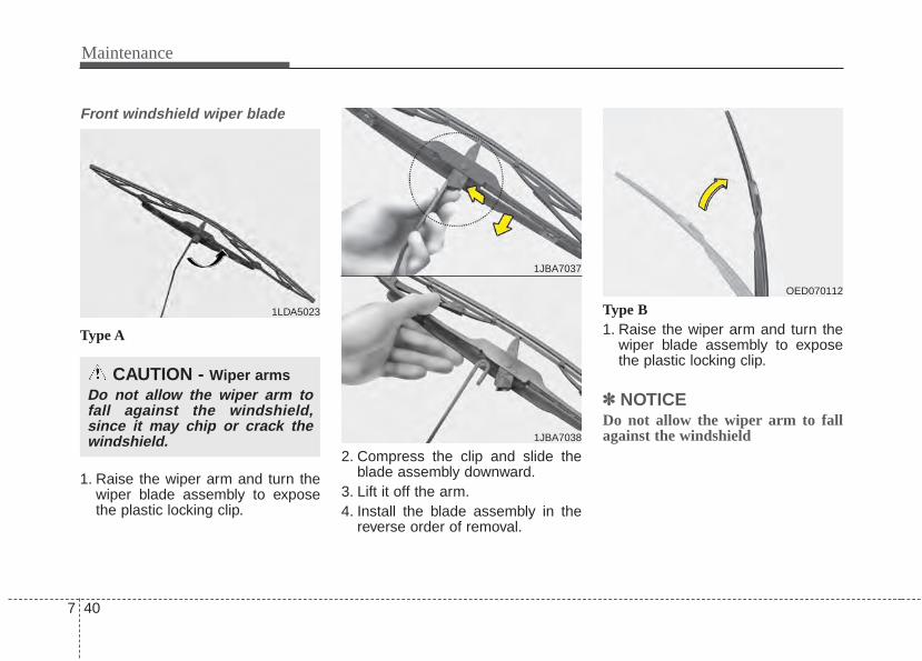
Maintenance
407
Front windshield wiper blade
Type A
1. Raise the wiper arm and turn thewiper blade assembly to exposethe plastic locking clip.
2. Compress the clip and slide theblade assembly downward.
3. Lift it off the arm.4. Install the blade assembly in the
reverse order of removal.
Type B1. Raise the wiper arm and turn the
wiper blade assembly to exposethe plastic locking clip.
✽✽ NOTICEDo not allow the wiper arm to fallagainst the windshield
1LDA5023
CAUTION - Wiper armsDo not allow the wiper arm tofall against the windshield,since it may chip or crack thewindshield.
1JBA7037
1JBA7038
OED070112
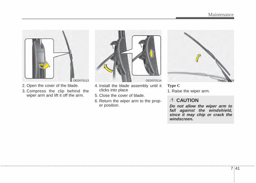
7 41
Maintenance
2. Open the cover of the blade.3. Compress the clip behind the
wiper arm and lift it off the arm.
4. Install the blade assembly until itclicks into place
5. Close the cover of blade.6. Return the wiper arm to the prop-
er position.
Type C1. Raise the wiper arm.
OED070113 OED070114
CAUTIONDo not allow the wiper arm tofall against the windshield,since it may chip or crack thewindscreen.
OHM078059
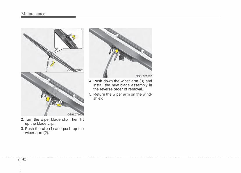
Maintenance
427
2. Turn the wiper blade clip. Then liftup the blade clip.
3. Push the clip (1) and push up thewiper arm (2).
4. Push down the wiper arm (3) andinstall the new blade assembly inthe reverse order of removal.
5. Return the wiper arm on the wind-shield.
OSBL071001
OSBL071003
OSBL071002

7 43
Maintenance
BATTERYFor best battery service
• Keep the battery securely mount-ed.
• Keep the battery top clean and dry.• Keep the terminals and connec-
tions clean, tight, and coated withpetroleum jelly or terminal grease.
• Rinse any spilled electrolyte fromthe battery immediately with asolution of water and baking soda.
• If the vehicle is not going to beused for an extended time, discon-nect the battery cables.
OVG079017L
WARNING - Batterydangers
Always read the follow-ing instructions carefullywhen handling a battery.
Keep lighted cigarettesand all other flames orsparks away from thebattery.
Hydrogen, a highly com-bustible gas, is alwayspresent in battery cellsand may explode if ignit-ed.
Keep batteries out of thereach of childrenbecause batteries con-tain highly corrosiveSULFURIC ACID. Do notallow battery acid tocontact your skin, eyes,clothing or paint finish.
(Continued)
(Continued)
If any electrolyte getsinto your eyes, flushyour eyes with cleanwater for at least 15 min-utes and get immediatemedical attention.If electrolyte gets onyour skin, thoroughlywash the contacted area.If you feel pain or burn-ing sensation, get med-ical attention immediate-ly.
Wear eye protectionwhen charging or work-ing near a battery.Always provide ventila-tion when working in anenclosed space.
(Continued)
Maintenance
447
Battery rechargingYour vehicle has a maintenance-free,calcium-based battery.• If the battery becomes discharged
in a short time (because, for exam-ple, the headlights or interior lightswere left on while the vehicle wasnot in use), recharge it by slowcharging (trickle) for 10 hours.
• If the battery gradually dischargesbecause of high electric load whilethe vehicle is being used, rechargeit at 20-30A for two hours.
CAUTIONIf you connect unauthorizedelectronic devices to the bat-tery, the battery may be dis-charged. Never use unautho-rized devices.
(Continued)
An inappropriately dis-posed battery can beharmful to the environ-ment and human health.Dispose the batteryaccording to your locallaw(s) or regulation.
• When lifting a plastic-casedbattery, excessive pressureon the case may cause batteryacid to leak, resulting in per-sonal injury. Lift with a batterycarrier or with your hands onopposite corners.
• Never attempt to recharge thebattery when the batterycables are connected.
• The electrical ignition systemworks with high voltage.Never touch these compo-nents with the engine runningor the ignition switched on.
Failure to follow the abovewarnings can result in seriousbodily injury or death.
7 45
Maintenance
Reset itemsItems should be reset after the bat-tery has been discharged or the bat-tery has been disconnected.• Auto up/down window
(See section 4)• Sunroof (See section 4)• Trip computer (See section 4)• Climate control system
(See section 4)• Clock (See section 4)• Audio (See section 4)WARNING
• Before performing mainte-nance or recharging the bat-tery, turn off all accessoriesand stop the engine.
• The negative battery cablemust be removed first andinstalled last when the batteryis disconnected.
WARNING - Rechargingbattery
When recharging the battery,observe the following precau-tions:• The battery must be removed
from the vehicle and placed inan area with good ventilation.
• Do not allow cigarettes,sparks, or flame near the bat-tery.
• Watch the battery duringcharging, and stop or reducethe charging rate if the batterycells begin gassing (boiling)violently or if the temperatureof the electrolyte of any cellexceeds 49°C (120°F).
• Wear eye protection whenchecking the battery duringcharging.
• Disconnect the battery charg-er in the following order.
(Continued)
(Continued)1. Turn off the battery charger
main switch.2. Unhook the negative clamp
from the negative battery ter-minal.
3. Unhook the positive clampfrom the positive battery ter-minal.

Maintenance
467
TIRES AND WHEELSTire care For proper maintenance, safety, andmaximum fuel economy, you mustalways maintain recommended tireinflation pressures and stay withinthe load limits and weight distributionrecommended for your vehicle.
Recommended cold tire infla-tion pressuresAll tire pressures (including thespare) should be checked when thetires are cold. “Cold Tires” means thevehicle has not been driven for atleast three hours or driven less than1.6 km (one mile).Recommended pressures must bemaintained for the best ride, vehiclehandling, and minimum tire wear.For recommended inflation pressure,refer to “Tire and wheels” in section8.
All specifications (sizes and pres-sures) can be found on a labelattached to the driver’s side centerpillar.
OBH088004N
WARNING - Tire under-inflation
Severe underinflation (70 kPa(10 psi) or more) can lead tosevere heat build-up, causingblowouts, tread separation andother tire failures that can resultin the loss of vehicle controlleading to severe injury ordeath. This risk is much higheron hot days and when drivingfor long periods at high speeds.
CAUTION• Underinflation also results in
excessive wear, poor handlingand reduced fuel economy.Wheel deformation also ispossible. Keep your tire pres-sures at the proper levels. If atire frequently needs refilling,have it checked by an author-ized Kia dealer.
• Overinflation produces aharsh ride, excessive wear atthe center of the tire tread, anda greater possibility of dam-age from road hazards.
7 47
Maintenance
Checking tire inflation pres-sureCheck your tires once a month ormore.Also, check the tire pressure of thespare tire.
How to checkUse a good quality gauge to checktire pressure. You cannot tell if yourtires are properly inflated simply bylooking at them. Radial tires maylook properly inflated even whenthey're underinflated.Check the tire's inflation pressurewhen the tires are cold. - "Cold"means your vehicle has been sittingfor at least three hours or driven nomore than 1.6 km (1 mile).
WARNING - Tire InflationOverinflation or underinflationcan reduce tire life, adverselyaffect vehicle handling, andlead to sudden tire failure. Thiscould result in loss of vehiclecontrol and potential injury.
CAUTION - Tire pressureAlways observe the following:• Check tire pressure when the
tires are cold. (After vehiclehas been parked for at leastthree hours or hasn't beendriven more than 1.6 km (onemile) since startup.)
• Check the pressure of yourspare tire each time you checkthe pressure of other tires.
• Never overload your vehicle.Be careful not to overload avehicle luggage rack if yourvehicle is equipped with one.
• Worn, old tires can cause acci-dents. If your tread is badlyworn, or if your tires havebeen damaged, replace them.
CAUTION• Warm tires normally exceed
recommended cold tire pres-sures by 4 to 6 psi (28 to 41kPa). Do not release air fromwarm tires to adjust the pres-sure or the tires will be under-inflated.
• Be sure to reinstall the tireinflation valve caps. Withoutthe valve cap, dirt or moisturecould get into the valve coreand cause air leakage. If avalve cap is missing, install anew one as soon as possible.
Maintenance
487
Remove the valve cap from the tirevalve stem. Press the tire gauge firm-ly onto the valve to get a pressuremeasurement. If the cold tire inflationpressure matches the recommendedpressure on the tire and loadinginformation label, no further adjust-ment is necessary. If the pressure islow, add air until you reach the rec-ommended amount.If you overfill the tire, release air bypushing on the metal stem in thecenter of the tire valve. Recheck thetire pressure with the tire gauge. Besure to put the valve caps back onthe valve stems. They help preventleaks by keeping out dirt and mois-ture.
Tire rotation To equalize tread wear, it is recom-mended that the tires be rotatedevery 12,000 km (7,500 miles) orsooner if irregular wear develops.During rotation, check the tires forcorrect balance.When rotating tires, check for unevenwear and damage. Abnormal wear isusually caused by incorrect tire pres-sure, improper wheel alignment, out-of-balance wheels, severe braking orsevere cornering. Look for bumps orbulges in the tread or side of tire.Replace the tire if you find either ofthese conditions. Replace the tire iffabric or cord is visible. After rotation,be sure to bring the front and rear tirepressures to specification and checklug nut tightness.Refer to “Tire and wheels” in section8.
WARNING• Inspect your tires frequently
for proper inflation as well aswear and damage. Always usea tire pressure gauge.
• Tires with too much or too littlepressure wear unevenly caus-ing poor handling, loss of vehi-cle control, and sudden tirefailure leading to accidents,injuries, and even death. Therecommended cold tire pres-sure for your vehicle can befound in this manual and onthe tire label located on the dri-ver's side center pillar.
• Worn tires can cause acci-dents. Replace tires that areworn, show uneven wear, orare damaged.
• Remember to check the pres-sure of your spare tire. Kiarecommends that you checkthe spare every time youcheck the pressure of theother tires on your vehicle.
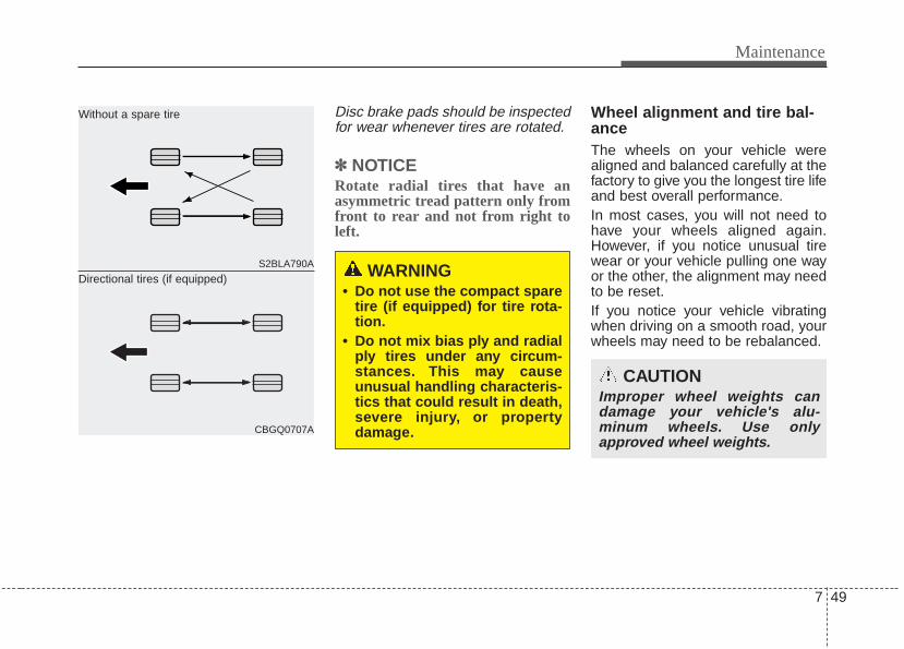
7 49
Maintenance
Disc brake pads should be inspectedfor wear whenever tires are rotated.
✽✽ NOTICERotate radial tires that have anasymmetric tread pattern only fromfront to rear and not from right toleft.
Wheel alignment and tire bal-ance The wheels on your vehicle werealigned and balanced carefully at thefactory to give you the longest tire lifeand best overall performance.In most cases, you will not need tohave your wheels aligned again.However, if you notice unusual tirewear or your vehicle pulling one wayor the other, the alignment may needto be reset.If you notice your vehicle vibratingwhen driving on a smooth road, yourwheels may need to be rebalanced.
S2BLA790A
CBGQ0707A
Without a spare tire
Directional tires (if equipped) WARNING• Do not use the compact spare
tire (if equipped) for tire rota-tion.
• Do not mix bias ply and radialply tires under any circum-stances. This may causeunusual handling characteris-tics that could result in death,severe injury, or propertydamage.
CAUTIONImproper wheel weights candamage your vehicle's alu-minum wheels. Use onlyapproved wheel weights.
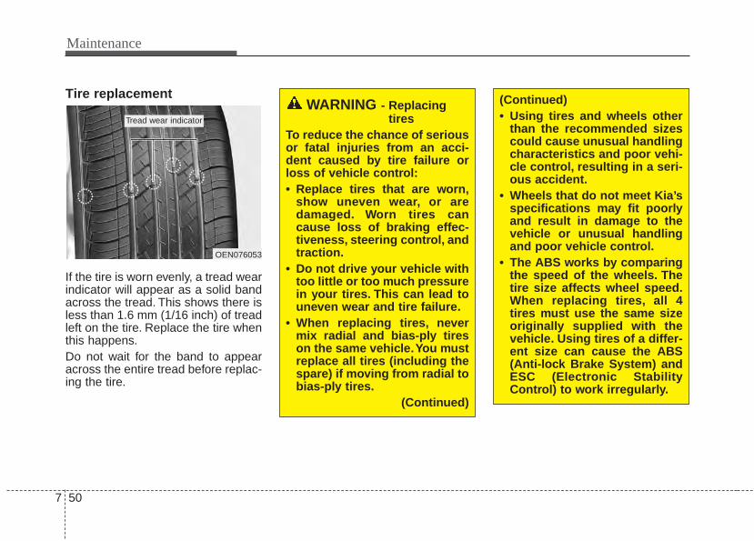
Maintenance
507
Tire replacement
If the tire is worn evenly, a tread wearindicator will appear as a solid bandacross the tread. This shows there isless than 1.6 mm (1/16 inch) of treadleft on the tire. Replace the tire whenthis happens.Do not wait for the band to appearacross the entire tread before replac-ing the tire.
OEN076053
Tread wear indicator
WARNING - Replacingtires
To reduce the chance of seriousor fatal injuries from an acci-dent caused by tire failure orloss of vehicle control:• Replace tires that are worn,
show uneven wear, or aredamaged. Worn tires cancause loss of braking effec-tiveness, steering control, andtraction.
• Do not drive your vehicle withtoo little or too much pressurein your tires. This can lead touneven wear and tire failure.
• When replacing tires, nevermix radial and bias-ply tireson the same vehicle.You mustreplace all tires (including thespare) if moving from radial tobias-ply tires.
(Continued)
(Continued)• Using tires and wheels other
than the recommended sizescould cause unusual handlingcharacteristics and poor vehi-cle control, resulting in a seri-ous accident.
• Wheels that do not meet Kia’sspecifications may fit poorlyand result in damage to thevehicle or unusual handlingand poor vehicle control.
• The ABS works by comparingthe speed of the wheels. Thetire size affects wheel speed.When replacing tires, all 4tires must use the same sizeoriginally supplied with thevehicle. Using tires of a differ-ent size can cause the ABS(Anti-lock Brake System) andESC (Electronic StabilityControl) to work irregularly.
7 51
Maintenance
Compact spare tire replacement A compact spare tire has a shortertread life than a regular size tire.Replace it when you can see thetread wear indicator bars on the tire.The replacement compact spare tireshould be the same size and designtire as the one provided with yournew vehicle and should be mountedon the same compact spare tirewheel. The compact spare tire is notdesigned to be mounted on a regularsize wheel, and the compact sparetire wheel is not designed for mount-ing a regular size tire.
Wheel replacement When replacing the metal wheels forany reason, make sure the newwheels are equivalent to the originalfactory units in diameter, rim widthand offset.
Tire tractionTire traction can be reduced if youdrive on worn tires, tires that areimproperly inflated or on slipperyroad surfaces. Tires should bereplaced when tread wear indicatorsappear. Slow down whenever thereis rain, snow or ice on the road toreduce the possibility of losing con-trol of the vehicle.
Tire maintenance In addition to proper inflation, correctwheel alignment helps to decreasetire wear. If you find a tire is wornunevenly, have your dealer check thewheel alignment.When you have new tires installed,make sure they are balanced. Thiswill increase vehicle ride comfort andtire life. Additionally, a tire shouldalways be rebalanced if it is removedfrom the wheel.
WARNINGA wheel that is not the correctsize may adversely affect wheeland bearing life, braking andstopping abilities, handlingcharacteristics, ground clear-ance, body-to-tire clearance,snow chain clearance,speedometer and odometer cal-ibration, headlight aim andbumper height.
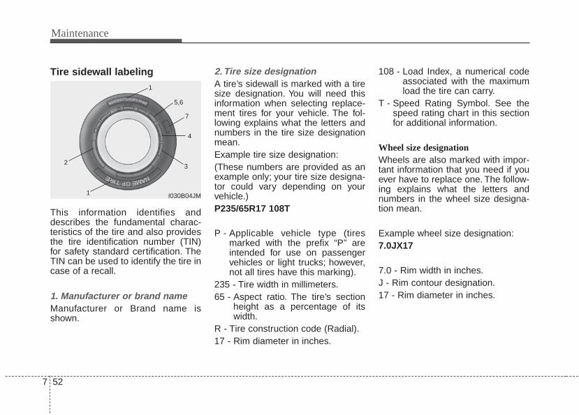
Maintenance
527
Tire sidewall labeling
This information identifies anddescribes the fundamental charac-teristics of the tire and also providesthe tire identification number (TIN)for safety standard certification. TheTIN can be used to identify the tire incase of a recall.
1. Manufacturer or brand nameManufacturer or Brand name isshown.
2. Tire size designation A tire’s sidewall is marked with a tiresize designation. You will need thisinformation when selecting replace-ment tires for your vehicle. The fol-lowing explains what the letters andnumbers in the tire size designationmean.Example tire size designation:(These numbers are provided as anexample only; your tire size designa-tor could vary depending on yourvehicle.)P235/65R17 108T
P - Applicable vehicle type (tiresmarked with the prefix “P’’ areintended for use on passengervehicles or light trucks; however,not all tires have this marking).
235 - Tire width in millimeters.65 - Aspect ratio. The tire’s section
height as a percentage of itswidth.
R - Tire construction code (Radial).17 - Rim diameter in inches.
108 - Load Index, a numerical codeassociated with the maximumload the tire can carry.
T - Speed Rating Symbol. See thespeed rating chart in this sectionfor additional information.
Wheel size designation Wheels are also marked with impor-tant information that you need if youever have to replace one. The follow-ing explains what the letters andnumbers in the wheel size designa-tion mean.
Example wheel size designation:7.0JX17
7.0 - Rim width in inches.J - Rim contour designation.17 - Rim diameter in inches.
I030B04JM
1
1
23
4
5,6
7

7 53
Maintenance
Tire speed ratings The chart below lists many of the dif-ferent speed ratings currently beingused for passenger vehicle tires. Thespeed rating is part of the tire sizedesignation on the sidewall of thetire. This symbol corresponds to thattire's designed maximum safe oper-ating speed.
3. Checking tire life (TIN : TireIdentification Number)
Any tires that are over 6 years old,based on the manufacturing date,(including the spare tire) should bereplaced by new ones. You can findthe manufacturing date on the tiresidewall (possibly on the inside of thewheel), displaying the DOT Code.The DOT Code is a series of num-bers on a tire consisting of numbersand English letters. The manufactur-ing date is designated by the last fourdigits (characters) of the DOT code.
DOT : XXXX XXXX OOOOThe front part of the DOT means aplant code number, tire size andtread pattern and the last four num-bers indicate week and year manu-factured.For example:DOT XXXX XXXX 1613 representsthat the tire was produced in the 16thweek of 2013.
WARNING - Tire ageTires degrade over time, evenwhen they are not being used.Regardless of the remainingtread, we recommend that tiresbe replaced after approximatelysix (6) years of normal service.Heat caused by hot climates orfrequent high loading condi-tions can accelerate the agingprocess. Failure to follow thiswarning can result in suddentire failure, which could lead toa loss of control and an acci-dent involving serious injury ordeath.
S 180 km/h (112 mph)T 190 km/h (118 mph)H 210 km/h (130 mph)V 240 km/h (149 mph)Z 240 km/h (Above 149 mph)
Maximum SpeedSpeedRatingSymbol
Maintenance
547
4. Tire ply composition and mate-rial
The number of layers or plies of rub-ber-coated fabric in the tire. Tiremanufacturers also must indicate thematerials in the tire, which includesteel, nylon, polyester, and others.The letter "R" means radial ply con-struction; the letter "D" means diago-nal or bias ply construction; and theletter "B" means belted-bias ply con-struction.
5. Maximum permissible inflationpressure
This number is the greatest amountof air pressure that should be put inthe tire. Do not exceed the maximumpermissible inflation pressure. Referto the Tire and Loading Informationlabel for recommended inflationpressure.
6. Maximum load ratingThis number indicates the maximumload in kilograms and pounds thatcan be carried by the tire. Whenreplacing the tires on the vehicle,always use a tire that has the sameload rating as the factory installedtire.
7. Uniform tire quality gradingQuality grades can be found whereapplicable on the tire sidewallbetween tread shoulder and maxi-mum section width.For example:TREADWEAR 200TRACTION AATEMPERATURE A
Tread wearThe tread wear grade is a compara-tive rating based on the wear rate ofthe tire when tested under controlledconditions on a specified govern-ment test course. For example, a tiregraded 150 would wear one-and-a-half times (1½) as well on the gov-ernment course as a tire graded 100.The relative performance of tiresdepends upon the actual conditionsof their use, however, and maydepart significantly from the normdue to variations in driving habits,service practices and differences inroad characteristics and climate.These grades are molded on theside-walls of passenger vehicle tires.The tires available as standard oroptional equipment on your vehiclemay vary with respect to grade.
7 55
Maintenance
Traction - AA, A, B & C The traction grades, from highest tolowest, are AA, A, B and C. Thosegrades represent the tire’s ability tostop on wet pavement as measuredunder controlled conditions on spec-ified government test surfaces ofasphalt and concrete. A tire markedC may have poor traction perform-ance.
Temperature -A, B & C The temperature grades are A (thehighest), B and C representing thetire's resistance to the generation ofheat and its ability to dissipate heatwhen tested under controlled condi-tions on a specified indoor laboratorytest wheel.Sustained high temperature cancause the material of the tire todegenerate and reduce tire life, andexcessive temperature can lead tosudden tire failure. Grades B and Arepresent higher levels of perform-ance on the laboratory test wheelthan the minimum required by law.
WARNING - Tire tempera-ture
The temperature grade for thistire is established for a tire thatis properly inflated and notoverloaded. Excessive speed,underinflation, or excessiveloading, either separately or incombination, can cause heatbuild-up and possible suddentire failure. This can cause lossof vehicle control and seriousinjury.
WARNING The traction grade assigned tothis tire is based on straight-ahead braking traction tests,and does not include accelera-tion, cornering, hydroplaning,or peak traction characteristics.
Maintenance
567
Tire terminology and definitionsAir Pressure: The amount of airinside the tire pressing outward onthe tire. Air pressure is expressed inpounds per square inch (psi) or kilo-pascal (kPa).Accessory Weight: This means thecombined weight of optional acces-sories. Some examples of optionalaccessories are, automatictransaxle, power seats, and air con-ditioning.Aspect Ratio: The relationship of atire's height to its width.Belt: A rubber coated layer of cordsthat is located between the plies andthe tread. Cords may be made fromsteel or other reinforcing materials.Bead: The tire bead contains steelwires wrapped by steel cords thathold the tire onto the rim.Bias Ply Tire: A pneumatic tire inwhich the plies are laid at alternateangles less than 90 degrees to thecenterline of the tread.
Cold Tire Pressure: The amount ofair pressure in a tire, measured inpounds per square inch (psi) or kilo-pascals (kPa) before a tire has builtup heat from driving.Curb Weight: This means the weightof a motor vehicle with standard andoptional equipment including themaximum capacity of fuel, oil andcoolant, but without passengers andcargo.DOT Markings: The DOT codeincludes the Tire IdentificationNumber (TIN), an alphanumeric des-ignator which can also identify thetire manufacturer, production plant,brand and date of production.GVWR: Gross Vehicle Weight RatingGAWR FRT: Gross Axle WeightRating for the Front Axle.GAWR RR: Gross Axle WeightRating for the Rear axle.
Intended Outboard Sidewall: Theside of an asymmetrical tire, thatmust always face outward whenmounted on a vehicle.Kilopascal (kPa): The metric unit forair pressure.Load Index: An assigned numberranging from 1 to 279 that corre-sponds to the load carrying capacityof a tire.Maximum Inflation Pressure: Themaximum air pressure to which acold tire may be inflated. The maxi-mum air pressure is molded onto thesidewall.Maximum Load Rating: The loadrating for a tire at the maximum per-missible inflation pressure for thattire.Maximum Loaded Vehicle Weight:The sum of curb weight; accessoryweight; vehicle capacity weight; andproduction options weight.Normal Occupant Weight: Thenumber of occupants a vehicle isdesigned to seat multiplied by 68 kg(150 pounds).
7 57
Maintenance
Occupant Distribution: Designatedseating positions.Outward Facing Sidewall: The sideof a asymmetrical tire that has a par-ticular side that faces outward whenmounted on a vehicle. The outwardfacing sidewall bears white letteringor bears manufacturer, brand, and/ormodel name molding that is higher ordeeper than the same moldings onthe inner facing sidewall.Passenger (P-Metric) Tire: A tireused on passenger cars and somelight duty trucks and multipurposevehicles.Recommended Inflation Pressure:Vehicle manufacturer's recommend-ed tire inflation pressure and shownon the tire placard.Radial Ply Tire: A pneumatic tire inwhich the ply cords that extend to thebeads are laid at 90 degrees to thecenterline of the tread.Rim: A metal support for a tire andupon which the tire beads are seat-ed.Sidewall: The portion of a tirebetween the tread and the bead.
Speed Rating: An alphanumericcode assigned to a tire indicating themaximum speed at which a tire canoperate.Traction: The friction between thetire and the road surface. Theamount of grip provided.Tread: The portion of a tire thatcomes into contact with the road.Treadwear Indicators: Narrowbands, sometimes called "wearbars," that show across the tread of atire when only 2/32 inch of treadremains.UTQGS: Uniform Tire QualityGrading Standards, a tire informationsystem that provides consumers withratings for a tire's traction, tempera-ture and treadwear. Ratings aredetermined by tire manufacturersusing government testing proce-dures. The ratings are molded intothe sidewall of the tire.Vehicle Capacity Weight: The num-ber of designated seating positionsmultiplied by 68 kg (150 lbs.) plus therated cargo and luggage load.
Vehicle Maximum Load on theTire: Load on an individual tire due tocurb and accessory weight plusmaximum occupant and cargoweight.Vehicle Normal Load on the Tire:Load on an individual tire that isdetermined by distributing to eachaxle its share of the curb weight,accessory weight, and normal occu-pant weight and driving by 2.Vehicle Placard: A label permanent-ly attached to a vehicle showing theoriginal equipment tire size and rec-ommended inflation pressure.
Maintenance
587
All season tires Kia specifies all season tires onsome models to provide good per-formance for use all year round,including snowy and icy road condi-tions. All season tires are identifiedby ALL SEASON and/or M+S (Mudand Snow) on the tire sidewall. Snowtires have better snow traction thanall season tires and may be moreappropriate in some areas.
Summer tires Kia specifies summer tires on somemodels to provide superior perform-ance on dry roads. Summer tire per-formance is substantially reduced insnow and ice. Summer tires do nothave the tire traction rating M+S(Mud and Snow) on the tire side wall.if you plan to operate your vehicle insnowy or icy conditions, Kia recom-mends the use of snow tires or allseason tires on all four wheels.
Snow tiresIf you equip your vehicle with snowtires, they should be the same sizeand have the same load capacity asthe original tires. Snow tires shouldbe installed on all four wheels; other-wise, poor handling may result.Snow tires should carry 28 kPa (4psi) more air pressure than the pres-sure recommended for the standardtires on the tire label on the driver'sside of the center pillar, or up to themaximum pressure shown on the tiresidewall, whichever is less.Do not drive faster than 120 km/h (75mph) when your vehicle is equippedwith snow tires.
Radial-ply tiresRadial-ply tires provide improvedtread life, road hazard resistance andsmoother high speed ride. The radi-al-ply tires used on this vehicle are ofbelted construction, and are selectedto complement the ride and handlingcharacteristics of your vehicle.Radial-ply tires have the same loadcarrying capacity, as bias-ply or biasbelted tires of the same size, and usethe same recommended inflationpressure. Mixing of radial-ply tireswith bias-ply or bias belted tires isnot recommended. Any combina-tions of radial-ply and bias-ply or biasbelted tires when used on the samevehicle will seriously deterioratevehicle handling. The best rule to fol-low is: Identical radial-ply tires shouldalways be used as a set of four.
7 59
Maintenance
Longer wearing tires can be moresusceptible to irregular tread wear. Itis very important to follow the tirerotation interval shown in this sectionto achieve the tread life potential ofthese tires. Cuts and punctures inradial-ply tires are repairable only inthe tread area, because of sidewallflexing. Consult your tire dealer forradial-ply tire repairs.
Low aspect ratio tire(if equipped)Low aspect ratio tires, whose aspectratio is lower than 50, are providedfor sporty looks.Because the low aspect ratio tiresare optimized for handling and brak-ing, it may be more uncomfortable toride in and there is more noise com-pare with normal tires.
CAUTIONBecause the sidewall of the lowaspect ratio tire is shorter thanthe normal, the wheel and tire ofthe low aspect ratio tire is easi-er to be damaged. So, follow theinstructions below.- When driving on a rough road
or off road, drive cautiouslybecause tires and wheels maybe damaged. And after driving,inspect tires and wheels.
- When passing over a pothole,speed bump, manhole, or curbstone, drive slowly so that thetires and wheels are not dam-aged.
- If the tire is impacted, we rec-ommend that you inspect thetire condition or contact anauthorized Kia dealer.
- To prevent damage to the tire,inspect the tire condition andpressure every 3,000km.
Maintenance
607
CAUTION• It is not easy to recognize the
tire damage with your owneyes. But if there is the slight-est hint of tire damage, eventhough you cannot see the tiredamage with your own eyes,have the tire checked orreplaced because the tiredamage may cause air leak-age from the tire.
• If the tire is damaged by driv-ing on a rough road, off road,pothole, manhole, or curbstone, it will not be covered bythe warranty.
• You can find out the tire infor-mation on the tire sidewall.
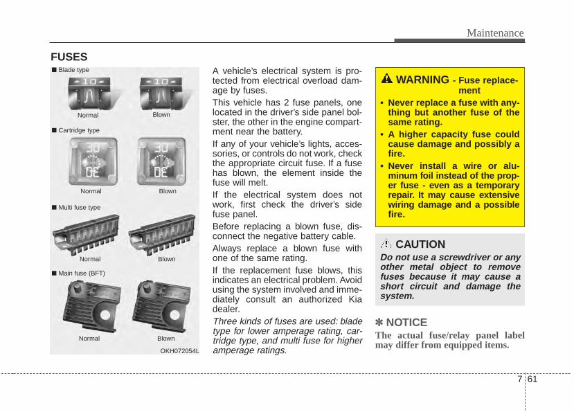
7 61
Maintenance
FUSESA vehicle’s electrical system is pro-tected from electrical overload dam-age by fuses.This vehicle has 2 fuse panels, onelocated in the driver’s side panel bol-ster, the other in the engine compart-ment near the battery.If any of your vehicle’s lights, acces-sories, or controls do not work, checkthe appropriate circuit fuse. If a fusehas blown, the element inside thefuse will melt.If the electrical system does notwork, first check the driver’s sidefuse panel.Before replacing a blown fuse, dis-connect the negative battery cable.Always replace a blown fuse withone of the same rating.If the replacement fuse blows, thisindicates an electrical problem. Avoidusing the system involved and imme-diately consult an authorized Kiadealer.Three kinds of fuses are used: bladetype for lower amperage rating, car-tridge type, and multi fuse for higheramperage ratings.
✽✽ NOTICEThe actual fuse/relay panel labelmay differ from equipped items.
WARNING - Fuse replace-ment
• Never replace a fuse with any-thing but another fuse of thesame rating.
• A higher capacity fuse couldcause damage and possibly afire.
• Never install a wire or alu-minum foil instead of the prop-er fuse - even as a temporaryrepair. It may cause extensivewiring damage and a possiblefire.
CAUTIONDo not use a screwdriver or anyother metal object to removefuses because it may cause ashort circuit and damage thesystem.
OKH072054L
Normal
Normal
■ Blade type
■ Cartridge type
■ Multi fuse type
Blown
Blown
Normal Blown
Normal Blown
■ Main fuse (BFT)
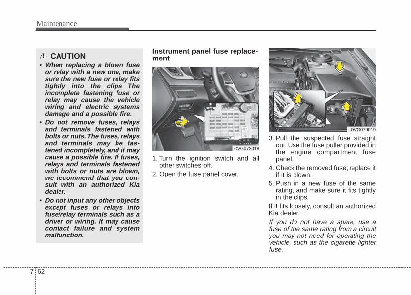
Maintenance
627
Instrument panel fuse replace-ment
1. Turn the ignition switch and allother switches off.
2. Open the fuse panel cover.
3. Pull the suspected fuse straightout. Use the fuse puller provided inthe engine compartment fusepanel.
4. Check the removed fuse; replace itif it is blown.
5. Push in a new fuse of the samerating, and make sure it fits tightlyin the clips.
If it fits loosely, consult an authorizedKia dealer.If you do not have a spare, use afuse of the same rating from a circuityou may not need for operating thevehicle, such as the cigarette lighterfuse.
CAUTION• When replacing a blown fuse
or relay with a new one, makesure the new fuse or relay fitstightly into the clips Theincomplete fastening fuse orrelay may cause the vehiclewiring and electric systemsdamage and a possible fire.
• Do not remove fuses, relaysand terminals fastened withbolts or nuts.The fuses, relaysand terminals may be fas-tened incompletely, and it maycause a possible fire. If fuses,relays and terminals fastenedwith bolts or nuts are blown,we recommend that you con-sult with an authorized Kiadealer.
• Do not input any other objectsexcept fuses or relays intofuse/relay terminals such as adriver or wiring. It may causecontact failure and systemmalfunction.
OVG073018
OVG079019
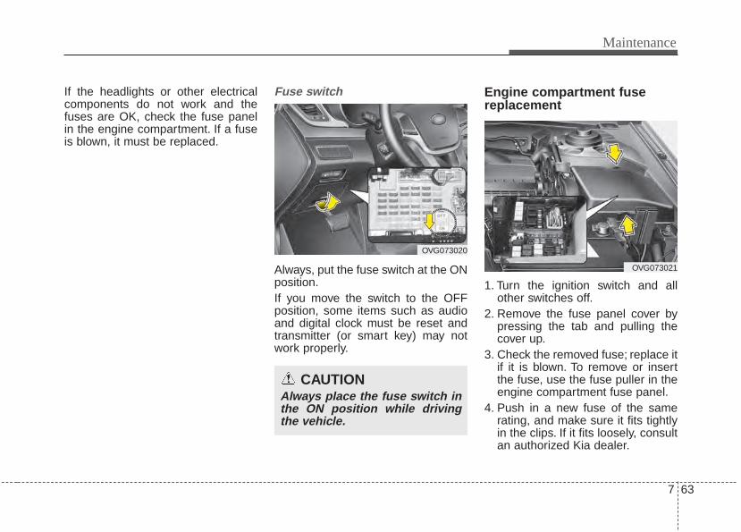
7 63
Maintenance
If the headlights or other electricalcomponents do not work and thefuses are OK, check the fuse panelin the engine compartment. If a fuseis blown, it must be replaced.
Fuse switch
Always, put the fuse switch at the ONposition.If you move the switch to the OFFposition, some items such as audioand digital clock must be reset andtransmitter (or smart key) may notwork properly.
Engine compartment fusereplacement
1. Turn the ignition switch and allother switches off.
2. Remove the fuse panel cover bypressing the tab and pulling thecover up.
3. Check the removed fuse; replace itif it is blown. To remove or insertthe fuse, use the fuse puller in theengine compartment fuse panel.
4. Push in a new fuse of the samerating, and make sure it fits tightlyin the clips. If it fits loosely, consultan authorized Kia dealer.
OVG073020
CAUTIONAlways place the fuse switch inthe ON position while drivingthe vehicle.
OVG073021
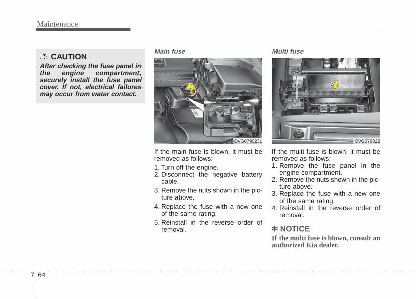
Maintenance
647
Main fuse
If the main fuse is blown, it must beremoved as follows:1. Turn off the engine.2. Disconnect the negative battery
cable.3. Remove the nuts shown in the pic-
ture above.4. Replace the fuse with a new one
of the same rating.5. Reinstall in the reverse order of
removal.
Multi fuse
If the multi fuse is blown, it must beremoved as follows:1. Remove the fuse panel in the
engine compartment.2. Remove the nuts shown in the pic-
ture above.3. Replace the fuse with a new one
of the same rating.4. Reinstall in the reverse order of
removal.
✽✽ NOTICEIf the multi fuse is blown, consult anauthorized Kia dealer.
CAUTIONAfter checking the fuse panel inthe engine compartment,securely install the fuse panelcover. If not, electrical failuresmay occur from water contact.
OVG079023L OVG079022
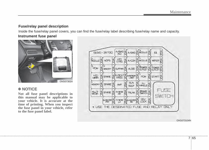
7 65
Maintenance
Instrument fuse panel
✽✽ NOTICENot all fuse panel descriptions inthis manual may be applicable toyour vehicle. It is accurate at thetime of printing. When you inspectthe fuse panel in your vehicle, referto the fuse panel label.
OVG073024
OVG073104N
Fuse/relay panel descriptionInside the fuse/relay panel covers, you can find the fuse/relay label describing fuse/relay name and capacity.
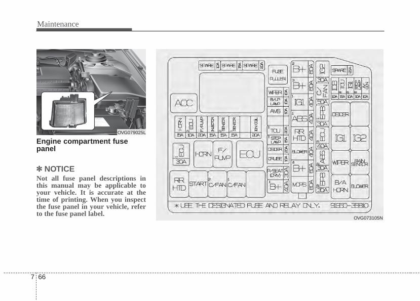
Maintenance
667
Engine compartment fusepanel
✽✽ NOTICENot all fuse panel descriptions inthis manual may be applicable toyour vehicle. It is accurate at thetime of printing. When you inspectthe fuse panel in your vehicle, referto the fuse panel label.
OVG073105N
OVG079025L
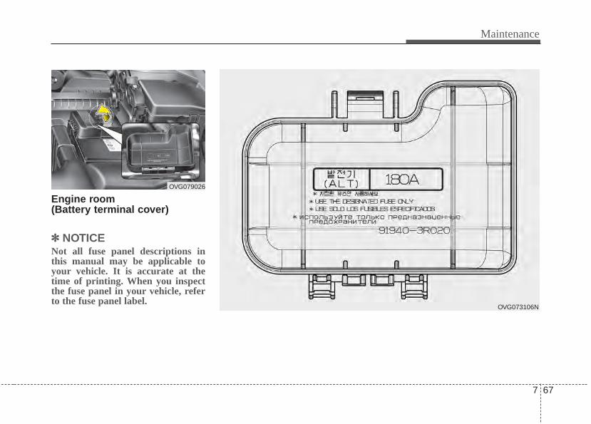
7 67
Maintenance
Engine room (Battery terminal cover)
✽✽ NOTICENot all fuse panel descriptions inthis manual may be applicable toyour vehicle. It is accurate at thetime of printing. When you inspectthe fuse panel in your vehicle, referto the fuse panel label.
OVG073106N
OVG079026

Maintenance
687
Instrument panel (Driver’s side fuse panel)NO. Fuse rating Description Protected component
MF1 10A MODULE 2
Tilt & Telescopic Module, Instrument cluster, Driver/Passenger Seat Warmer Module, Rear SeatWarmer Module LH/RH, IMS Control Module, Rear Parking Assist Sensor LH/RH, Rear ParkingAssist Sensor LH/RH(Center), Driver/Passenger Door Module, LDWS Camera Module, ElectroChromic Mirror, Room Lamp, MTS Module, Driver/Passenger CCS Control Module, Head LampLeveling Device Switch, Auto Head Lamp Leveling Device Module, Front Parking Assist SensorLH/RH, Head Lamp Leveling Device Actuator LH/RH, Console SW, BSD (Blind Spot Detection)Unit LH/RH Rear P/WDW HEATED Module
MF2 10A PDM 3 PDM, Smart Key Control Module
MF3 10A HTD MRR Driver Power Outside Mirror, Passenger Power Outside Mirror, A/C Control Module
MF4 10A MEMORY 1Auto Light & Photo Sensor, Data Link Connector, Driver/Passenger Foot Lamp, Instrument Cluster,Digital Clock, Rear Curtain Module, A/C Control Module, Room Lamp, Driver/Passenger DoorModule
MF5 15A MULTI MEDIA MTS Module, Audio, A/V & Navigation Head Unit, Audio Monitor
MF6 10A MDPS MDPS_SIG
MF7 10A MEMORY 2 RF Receiver
MF8 15A SPARE SPARE
MF9 10A SPARE SPARE
MF10 15A SPARE SPARE
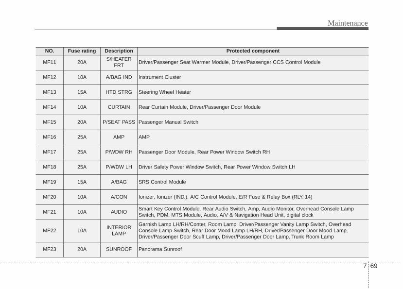
7 69
Maintenance
NO. Fuse rating Description Protected component
MF11 20AS/HEATER
FRTDriver/Passenger Seat Warmer Module, Driver/Passenger CCS Control Module
MF12 10A A/BAG IND Instrument Cluster
MF13 15A HTD STRG Steering Wheel Heater
MF14 10A CURTAIN Rear Curtain Module, Driver/Passenger Door Module
MF15 20A P/SEAT PASS Passenger Manual Switch
MF16 25A AMP AMP
MF17 25A P/WDW RH Passenger Door Module, Rear Power Window Switch RH
MF18 25A P/WDW LH Driver Safety Power Window Switch, Rear Power Window Switch LH
MF19 15A A/BAG SRS Control Module
MF20 10A A/CON Ionizer, Ionizer (IND.), A/C Control Module, E/R Fuse & Relay Box (RLY. 14)
MF21 10A AUDIOSmart Key Control Module, Rear Audio Switch, Amp, Audio Monitor, Overhead Console LampSwitch, PDM, MTS Module, Audio, A/V & Navigation Head Unit, digital clock
MF22 10AINTERIOR
LAMP
Garnish Lamp LH/RH/Conter, Room Lamp, Driver/Passenger Vanity Lamp Switch, OverheadConsole Lamp Switch, Rear Door Mood Lamp LH/RH, Driver/Passenger Door Mood Lamp,Driver/Passenger Door Scuff Lamp, Driver/Passenger Door Lamp, Trunk Room Lamp
MF23 20A SUNROOF Panorama Sunroof
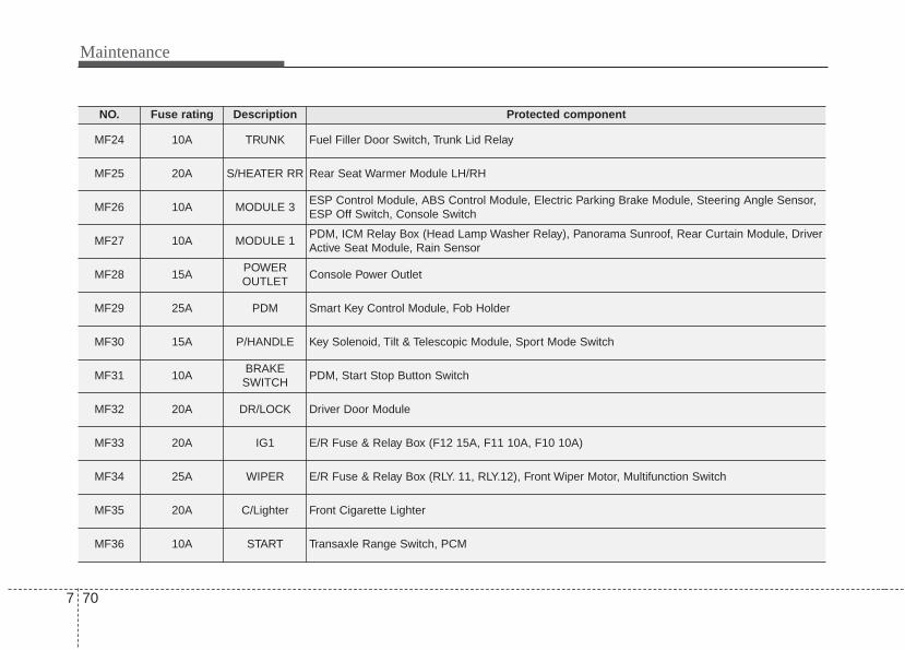
Maintenance
707
NO. Fuse rating Description Protected component
MF24 10A TRUNK Fuel Filler Door Switch, Trunk Lid Relay
MF25 20A S/HEATER RR Rear Seat Warmer Module LH/RH
MF26 10A MODULE 3ESP Control Module, ABS Control Module, Electric Parking Brake Module, Steering Angle Sensor,ESP Off Switch, Console Switch
MF27 10A MODULE 1PDM, ICM Relay Box (Head Lamp Washer Relay), Panorama Sunroof, Rear Curtain Module, DriverActive Seat Module, Rain Sensor
MF28 15APOWER OUTLET
Console Power Outlet
MF29 25A PDM Smart Key Control Module, Fob Holder
MF30 15A P/HANDLE Key Solenoid, Tilt & Telescopic Module, Sport Mode Switch
MF31 10ABRAKESWITCH
PDM, Start Stop Button Switch
MF32 20A DR/LOCK Driver Door Module
MF33 20A IG1 E/R Fuse & Relay Box (F12 15A, F11 10A, F10 10A)
MF34 25A WIPER E/R Fuse & Relay Box (RLY. 11, RLY.12), Front Wiper Motor, Multifunction Switch
MF35 20A C/Lighter Front Cigarette Lighter
MF36 10A START Transaxle Range Switch, PCM
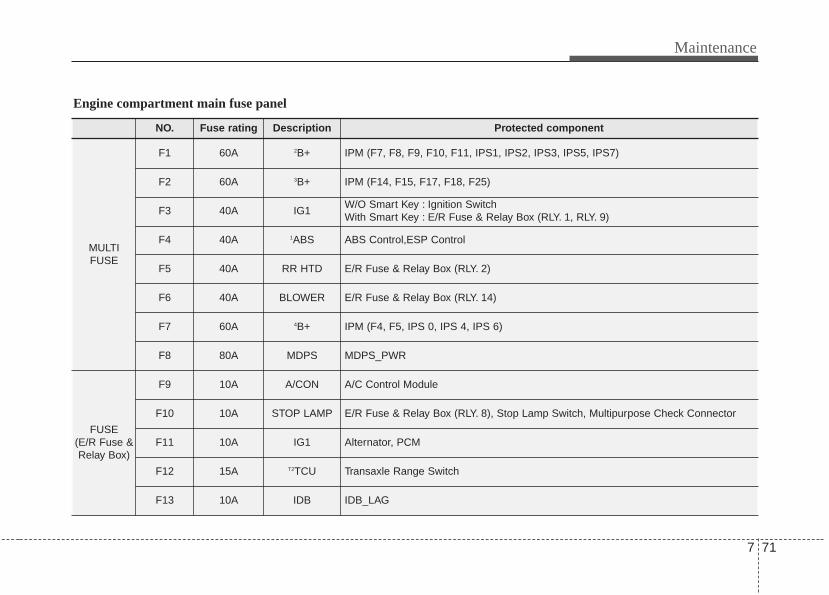
7 71
Maintenance
NO. Fuse rating Description Protected component
MULTIFUSE
F1 60A 2B+ IPM (F7, F8, F9, F10, F11, IPS1, IPS2, IPS3, IPS5, IPS7)
F2 60A 3B+ IPM (F14, F15, F17, F18, F25)
F3 40A IG1W/O Smart Key : Ignition Switch With Smart Key : E/R Fuse & Relay Box (RLY. 1, RLY. 9)
F4 40A 1ABS ABS Control,ESP Control
F5 40A RR HTD E/R Fuse & Relay Box (RLY. 2)
F6 40A BLOWER E/R Fuse & Relay Box (RLY. 14)
F7 60A 4B+ IPM (F4, F5, IPS 0, IPS 4, IPS 6)
F8 80A MDPS MDPS_PWR
FUSE(E/R Fuse &Relay Box)
F9 10A A/CON A/C Control Module
F10 10A STOP LAMP E/R Fuse & Relay Box (RLY. 8), Stop Lamp Switch, Multipurpose Check Connector
F11 10A IG1 Alternator, PCM
F12 15A T2TCU Transaxle Range Switch
F13 10A IDB IDB_LAG
Engine compartment main fuse panel

Maintenance
727
NO. Fuse rating Description Protected component
FUSE(E/R Fuse &Relay Box)
F14 30A IG2W/O Smart Key : E/R Fuse & Relay Box (RLY. 3), Ignition SwitchWith Smart Key : E/R Fuse & Relay Box (RLY. 3, RLY. 10)
F15 50A C/FAN E/R Fuse & Relay Box (RLY. 4, RLY. 5)
F16 30A 1EPB Electric Parking Brake Module
F17 40A 3ECU EMS Box (F35, F36, F37, F38)
F18 30A 2ABS ABS Control, ESP Control
F19 30A 2EPB Electric Parking Brake Module
F20 10A WIPER IPM (IPS Control Module)
F21 10A B/UP LAMPMTS Module, A/V & Navigation Head Unit, Rear Curtain Module,Electro Chromic Mirror, Rear Combination Lamp(In) LH/RH
F22 10A AMS Not Used
F23 20A - ICM Relay Box (Head Lamp Washer Realy)
F24 20A 1TCU PCM
F25 15A 1STOP LAMP E/R Fuse & Relay Box (RLY. 12), Stop Lamp Switch, Stop Lamp Signal Relay
F26 20A DEICER E/R Fuse & Relay Box (RLY. 7)

7 73
Maintenance
NO. Fuse rating Description Protected component
FUSE(E/R Fuse &Relay Box)
F27 10A CRUISE SCC (Smart Cruise Control) Radar
F28 30A P/SEAT (DRV)IMS Control Module, Driver Lumbar Support Switch, Driver Cushion Extension Switch, Driver Manual Switch
F29 40A 1B+ IPM (F29, F30, F31, F32, IPS 11, Leak Current Autocut Device)
FUSE(EMS Box)
F30 20A IGN COILG4KE : Ignition Coil #1, #2, #3, #4, CondenserG6DC : Ignition Coil #1, #2, #3, #4, #5, #6, Condenser #1, #2
F31 15A 1SENSOR
G4KE : Immobilizer Module, Camshaft Position Sensor #1, #2,Variable Intake Manifold Valve, Crankshaft Position Sensor,Oil Control Valve #1, #2, Canister Purge Control Solenoid Valve
G6DC : PCM, Immobilizer Module, Oxygen Sensor #1, #2, #3, #4
F32 15A 2SENSOR
G4KE : E/R Fuse & Relay Box (RLY. 5),Oxygen Sensor (Up, Down)
G6DC : Variable Intake Manifold Valve #1, #2, PCM,E/R Fuse & Relay Box (RLY. 5), Oil Control Valve #1, #2,#3, #4,Canister Purge Control Solenoid Valve,
F33 15A INJECTORG4KE : Injector #1, #2, #3, #4G6DC : Injector #1, #2, #3, #4, #5, #6, PCM
F34 20A F/FUMP E/R Fuse & Relay Box (RLY. 16)
F35 10A 2ECU PCM
F36 15A HORN E/R Fuse & Relay Box (RLY. 13), EMS Box (RLY. 15)
F37 30A 1ECU EMS Box (RLY. 17)
Maintenance
747
APPEARANCE CAREExterior careExterior general caution It is very important to follow the labeldirections when using any chemicalcleaner or polish. Read all warningand caution statements that appearon the label.
Finish maintenanceWashing To help protect your vehicle’s finishfrom rust and deterioration, wash itthoroughly and frequently at leastonce a month with lukewarm or coldwater.If you use your vehicle for off-roaddriving, you should wash it after eachoff-road trip. Pay special attention tothe removal of any accumulation ofsalt, dirt, mud, and other foreignmaterials. Make sure the drain holesin the lower edges of the doors androcker panels are kept clear andclean.Insects, tar, tree sap, bird droppings,industrial pollution and similardeposits can damage your vehicle’sfinish if not removed immediately.Even prompt washing with plainwater may not completely remove allthese deposits. A mild soap, safe foruse on painted surfaces, may beused.After washing, rinse the vehicle thor-oughly with lukewarm or cold water.Do not allow soap to dry on the fin-ish.
CAUTION• Do not use strong soap, chem-
ical detergents or hot water,and do not wash the vehicle indirect sunlight or when thebody of the vehicle is warm.
• Be careful when washing theside windows of your vehicle.Especailly, with high-pressurewater. Water may leak throughthe windows and wet the inte-rior.
• To prevent damage to theplastic parts and lamps, donot clean with chemical sol-vents or strong detergents.
WARNING - Wet brakesAfter washing the vehicle, testthe brakes while driving slowlyto see if they have been affectedby water. If braking performanceis impaired, dry the brakes byapplying them lightly whilemaintaining a slow forwardspeed.
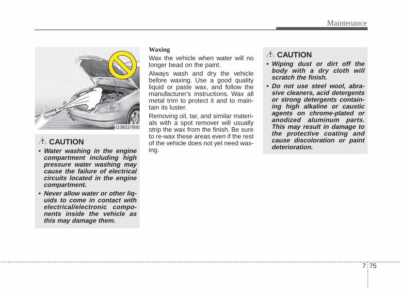
7 75
Maintenance
WaxingWax the vehicle when water will nolonger bead on the paint.Always wash and dry the vehiclebefore waxing. Use a good qualityliquid or paste wax, and follow themanufacturer’s instructions. Wax allmetal trim to protect it and to main-tain its luster.Removing oil, tar, and similar materi-als with a spot remover will usuallystrip the wax from the finish. Be sureto re-wax these areas even if the restof the vehicle does not yet need wax-ing.
CAUTION• Water washing in the engine
compartment including highpressure water washing maycause the failure of electricalcircuits located in the enginecompartment.
• Never allow water or other liq-uids to come in contact withelectrical/electronic compo-nents inside the vehicle asthis may damage them.
CAUTION• Wiping dust or dirt off the
body with a dry cloth willscratch the finish.
• Do not use steel wool, abra-sive cleaners, acid detergentsor strong detergents contain-ing high alkaline or causticagents on chrome-plated oranodized aluminum parts.This may result in damage tothe protective coating andcause discoloration or paintdeterioration.
OJB037800

Maintenance
767
Finish damage repair Deep scratches or stone chips in thepainted surface must be repairedpromptly. Exposed metal will quicklyrust and may develop into a majorrepair expense.
✽✽ NOTICEIf your vehicle is damaged andrequires any metal repair orreplacement, be sure the body shopapplies anti-corrosion materials tothe parts repaired or replaced.
Bright-metal maintenance• To remove road tar and insects,
use a tar remover, not a scraper orother sharp object.
• To protect the surfaces of bright-metal parts from corrosion, apply acoating of wax or chrome preser-vative and rub to a high luster.
• During winter weather or in coastalareas, cover the bright metal partswith a heavier coating of wax orpreservative. If necessary, coat theparts with non-corrosive petroleumjelly or other protective compound.
Underbody maintenanceCorrosive materials used for ice andsnow removal and dust control maycollect on the underbody. If thesematerials are not removed, acceler-ated rusting can occur on underbodyparts such as the fuel lines, frame,floor pan and exhaust system, eventhough they have been treated withrust protection.Thoroughly flush the vehicle under-body and wheel openings with luke-warm or cold water once a month,after off-road driving and at the endof each winter. Pay special attentionto these areas because it is difficultto see all the mud and dirt. It will domore harm than good to wet downthe road grime without removing it.The lower edges of the doors, rockerpanels, and frame members havedrain holes that should not beallowed to clog with dirt; trappedwater in these areas can cause rust-ing.
7 77
Maintenance
Aluminum or chrome wheel main-tenance The aluminum or chrome wheels arecoated with a clear protective finish.• Do not use any abrasive cleaner,
polishing compound, solvent, orwire brushes on aluminum orchrome wheels. They may scratchor damage the finish.
• Clean the wheel when it hascooled.
• Use only a mild soap or neutraldetergent, and rinse thoroughlywith water. Also, be sure to cleanthe wheels after driving on saltedroads. This helps prevent corro-sion.
• Avoid washing the wheels withhighspeed vehicle wash brushes.
• Do not use any alkaline or aciddetergents It may damage and cor-rode the aluminum or chromewheels coated with a clear protec-tive finish.
Corrosion protectionProtecting your vehicle from corro-sionBy using the most advanced designand construction practices to combatcorrosion, we produce vehicles ofthe highest quality. However, this isonly part of the job. To achieve thelong-term corrosion resistance yourvehicle can deliver, the owner'scooperation and assistance is alsorequired.
Common causes of corrosionThe most common causes of corro-sion on your vehicle are:• Road salt, dirt and moisture that is
allowed to accumulate underneaththe vehicle.
• Removal of paint or protectivecoatings by stones, gravel, abra-sion or minor scrapes and dentswhich leave unprotected metalexposed to corrosion.
WARNINGAfter washing the vehicle, testthe brakes while driving slowlyto see if they have been affectedby water. If braking performanceis impaired, dry the brakes byapplying them lightly whilemaintaining a slow forwardspeed.
Maintenance
787
High-corrosion areasIf you live in an area where your vehi-cle is regularly exposed to corrosivematerials, corrosion protection isparticularly important. Some of thecommon causes of accelerated cor-rosion are road salts, dust controlchemicals, ocean air and industrialpollution.
Moisture breeds corrosionMoisture creates the conditions inwhich corrosion is most likely tooccur. For example, corrosion isaccelerated by high humidity, partic-ularly when temperatures are justabove freezing. In such conditions,the corrosive material is kept in con-tact with the vehicle’s surface bymoisture that evaporates slowly.Mud is particularly corrosivebecause it dries slowly and holdsmoisture in contact with the vehicle.Although the mud appears to be dry,it can still retain the moisture andpromote corrosion.
High temperatures can also acceler-ate corrosion of parts that are notproperly ventilated so the moisturecan be dispersed. For all these rea-sons, it is particularly important tokeep your vehicle clean and free ofmud or accumulations of other mate-rials. This applies not only to the vis-ible surfaces but particularly to theunderside of the vehicle.
To help prevent corrosionYou can help prevent corrosion frombeginning by observing the following:
Keep your vehicle cleanThe best way to prevent corrosion isto keep your vehicle clean and freeof corrosive materials. Attention tothe underside of the vehicle is partic-ularly important.
• If you live in a high-corrosion areawhere road salts are used, nearthe ocean, areas with industrialpollution, acid rain, etc., you shouldtake extra care to prevent corro-sion. In winter, hose off the under-side of your vehicle at least once amonth and be sure to clean theunderside thoroughly when winteris over.
• When cleaning underneath thevehicle, give particular attention tothe components under the fendersand other areas that are hiddenfrom view. Do a thorough job; justdampening the accumulated mudrather than washing it away willaccelerate corrosion rather thanprevent it. Water under high pres-sure and steam are particularlyeffective in removing accumulatedmud and corrosive materials.
7 79
Maintenance
• When cleaning lower door panels,rocker panels and frame members,be sure that drain holes are keptopen so that moisture can escapeand not be trapped inside to accel-erate corrosion.
Keep your garage dryDon't park your vehicle in a damp,poorly ventilated garage. This cre-ates a favorable environment for cor-rosion. This is particularly true if youwash your vehicle in the garage ordrive it into the garage when it is stillwet or covered with snow, ice ormud. Even a heated garage can con-tribute to corrosion unless it is wellventilated so moisture is dispersed.
Keep paint and trim in good condi-tionScratches or chips in the finishshould be covered with "touch-up"paint as soon as possible to reducethe possibility of corrosion. If baremetal is showing through, the atten-tion of a qualified body and paintshop is recommended.
Bird droppings : Bird droppings arehighly corrosive and may damagepainted surfaces in just a few hours.Always remove bird droppings assoon as possible.
Don't neglect the interiorMoisture can collect under the floormats and carpeting and cause corro-sion. Check under the mats periodi-cally to be sure the carpeting is dry.Use particular care if you carry fertil-izers, cleaning materials or chemi-cals in the vehicle.These should be carried only inproper containers and any spills orleaks should be cleaned up, flushedwith clean water and thoroughlydried.
Interior careInterior general precautions Prevent chemicals such as perfume,cosmetic oil, sun cream, hand clean-er, and air freshener from contactingthe interior parts because they maycause damage or discoloration. Ifthey do contact the interior parts,wipe them off immediately. If neces-sary, use a vinyl cleaner, see productinstructions for correct usage.
CAUTIONNever allow water or other liq-uids to come in contact withelectrical/ electronic compo-nents inside the vehicle as thismay damage them.
Maintenance
807
Cleaning the upholstery and inte-rior trim Vinyl Remove dust and loose dirt fromvinyl with a whisk broom or vacuumcleaner. Clean vinyl surfaces with avinyl cleaner.
Fabric Remove dust and loose dirt from fab-ric with a whisk broom or vacuumcleaner. Clean with a mild soap solu-tion recommended for upholstery orcarpets. Remove fresh spots imme-diately with a fabric spot cleaner. Iffresh spots do not receive immediateattention, the fabric can be stainedand its color can be affected. Also, itsfire-resistant properties can bereduced if the material is not proper-ly maintained.
Cleaning the lap/shoulder beltwebbing Clean the belt webbing with any mildsoap solution recommended forcleaning upholstery or carpet. Followthe instructions provided with thesoap. Do not bleach or re-dye thewebbing because this may weakenit.
Cleaning the interior windowglass If the interior glass surfaces of thevehicle become fogged (that is, cov-ered with an oily, greasy or waxyfilm), they should be cleaned with aglass cleaner. Follow the directionson the glass cleaner container.
CAUTIONUsing anything but recommend-ed cleaners and proceduresmay affect the fabric’s appear-ance and fire-resistant proper-ties.
CAUTIONWhen cleaning leather products(steering wheel, seats etc.), useneutral detergents or low alco-hol content solutions. If you usehigh alcohol content solutionsor acid/alkaline detergents, thecolor of the leather may fade orthe surface may get stripped off.
CAUTIONDo not scrape or scratch theinside of the rear window. Thismay result in damage of the rearwindow defroster grid.
7 81
Maintenance
EMISSION CONTROL SYSTEMThe emission control system of yourvehicle is covered by a written limitedwarranty. Please see the warrantyinformation contained in theWarranty & Maintenance booklet inyour vehicle.Your vehicle is equipped with anemission control system to meet allapplicable emission regulations.There are three emission controlsystems, as follows.
(1) Crankcase emission control sys-tem
(2) Evaporative emission control sys-tem
(3) Exhaust emission control system
In order to assure the proper functionof the emission control systems, it isrecommended that you have yourvehicle inspected and maintained byan authorized Kia dealer in accor-dance with the maintenance sched-ule in this manual.
Caution for the Inspection andMaintenance Test (With ElectronicStability Control (ESC) system)• To prevent the vehicle from mis-
firing during dynamometer test-ing, turn the Electronic StabilityControl (ESC) system off bypressing the ESC switch.
• After dynamometer testing iscompleted, turn the ESC systemback on by pressing the ESCswitch again.
1. Crankcase emission controlsystem
The positive crankcase ventilationsystem is employed to prevent airpollution caused by blow-by gasesbeing emitted from the crankcase.This system supplies fresh filtered airto the crankcase through the airintake hose. Inside the crankcase,the fresh air mixes with blow-bygases, which then pass through thePCV valve into the induction system.
2. Evaporative emission con-trol (including ORVR:Onboard Refueling VaporRecovery) system
The Evaporative Emission ControlSystem is designed to prevent fuelvapors from escaping into the atmos-phere.(The ORVR system is designed toallow the vapors from the fuel tank tobe loaded into a canister while refu-eling at the gas station, preventingthe escape of fuel vapors into theatmosphere.)
Maintenance
827
CanisterFuel vapors generated inside the fueltank are absorbed and stored in theonboard canister. When the engine isrunning, the fuel vapors absorbed inthe canister are drawn into the surgetank through the purge control sole-noid valve.
Purge Control Solenoid Valve(PCSV)The purge control solenoid valve iscontrolled by the Engine ControlModule (ECM); when the enginecoolant temperature is low duringidling, the PCSV closes so that evap-orated fuel is not taken into theengine. After the engine warms upduring ordinary driving, the PCSVopens to introduce evaporated fuel tothe engine.
3. Exhaust emission control system
The Exhaust Emission ControlSystem is a highly effective systemwhich controls exhaust emissionswhile maintaining good vehicle per-formance.
Vehicle modifications This vehicle should not be modified.Modification of your vehicle couldaffect its performance, safety ordurability and may even violate gov-ernmental safety and emissions reg-ulations.In addition, damage or performanceproblems resulting from any modifi-cation may not be covered underwarranty.• If you use unauthorized electronic
devices, it may cause the vehicle tooperate abnormally, wire damage,battery discharge and fire. For yoursafety, do not use unauthorizedelectronic devices.
Engine exhaust gas precautions(carbon monoxide) • Carbon monoxide can be present
with other exhaust fumes.Therefore, if you smell exhaustfumes of any kind inside your vehi-cle, have it inspected and repairedimmediately. If you ever suspectexhaust fumes are coming intoyour vehicle, drive it only with allthe windows fully open. Have yourvehicle checked and repairedimmediately.
7 83
Maintenance
• Do not operate the engine in con-fined or closed areas (such asgarages) any more than what isnecessary to move the vehicle in orout of the area.
• When the vehicle is stopped in anopen area for more than a shorttime with the engine running,adjust the ventilation system (asneeded) to draw outside air into thevehicle.
• Never sit in a parked or stoppedvehicle for any extended time withthe engine running.
• When the engine stalls or fails tostart, excessive attempts to restartthe engine may cause damage tothe emission control system.
Operating precautions for catalyt-ic converters (if equipped)
WARNING - Fire• A hot exhaust system can
ignite flammable items underyour vehicle. Do not park, idleor drive the vehicle over ornear flammable objects, suchas grass, vegetation, paper,leaves, etc.
• The exhaust system and cat-alytic system are very hotwhile the engine is running orimmediately after the engineis turned off. Keep away fromthe exhaust system and cat-alytic, you may get burned.Also, do not remove the heatsink around the exhaust sys-tem, do not seal the bottom ofthe vehicle or do not coat thevehicle for corrosion control.It may present a fire risk undercertain conditions.
WARNING - ExhaustEngine exhaust gases containcarbon monoxide (CO). Thoughcolorless and odorless, it isdangerous and could be lethal ifinhaled. Follow the instructionson this page to avoid CO poi-soning.
Maintenance
847
Your vehicle is equipped with a cat-alytic converter emission controldevice.Therefore, the following precautionsmust be observed:• Use only UNLEADED FUEL for
gasoline engines.• Do not operate the vehicle when
there are signs of engine malfunc-tion, such as misfire or a noticeableloss of performance.
• Do not misuse or abuse theengine. Examples of misuse arecoasting with the ignition off anddescending steep grades in gearwith the ignition off.
• Do not operate the engine at highidle speed for extended periods (5minutes or more).
• Do not modify or tamper with anypart of the engine or emission con-trol system. All inspections andadjustments must be made by anauthorized Kia dealer.
• Avoid driving with a extremely lowfuel level. Running out of fuel couldcause the engine to misfire, dam-aging the catalytic converter.
Failure to observe these precautionscould result in damage to the catalyt-ic converter and to your vehicle.Additionally, such actions could voidyour warranties.
Specifications & Consumer information
Dimensions . . . . . . . . . . . . . . . . . . . . . . . . . . . . . . . . 8-2Tires and wheels . . . . . . . . . . . . . . . . . . . . . . . . . . . . 8-2Engine . . . . . . . . . . . . . . . . . . . . . . . . . . . . . . . . . . . . 8-3Weight/volume . . . . . . . . . . . . . . . . . . . . . . . . . . . . . 8-3Bulb wattage . . . . . . . . . . . . . . . . . . . . . . . . . . . . . . . 8-4Recommended lubricants and capacities . . . . . . . 8-5
• Recommended SAE viscosity number . . . . . . . . . . . . 8-6Vehicle identification number (VIN) . . . . . . . . . . . 8-7Vehicle certification label. . . . . . . . . . . . . . . . . . . . . 8-7Tire specification and pressure label . . . . . . . . . . . 8-8Engine number . . . . . . . . . . . . . . . . . . . . . . . . . . . . . 8-8
8
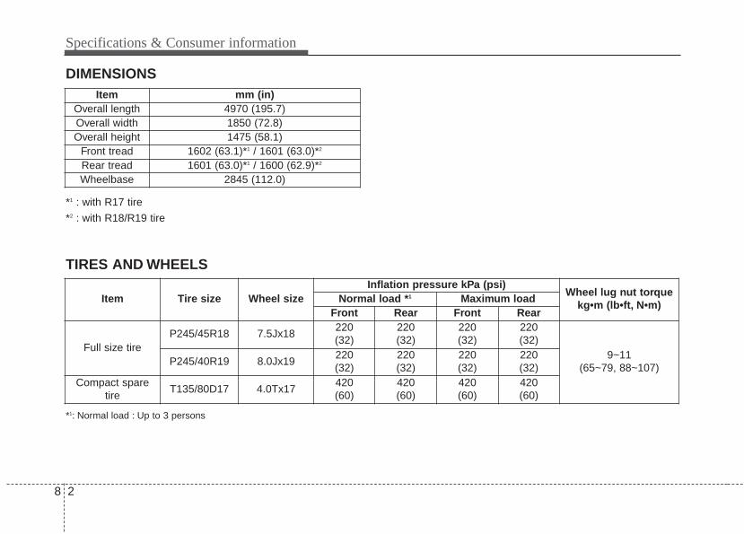
Specifications & Consumer information
28
DIMENSIONS
*1 : with R17 tire
*2 : with R18/R19 tire
Item mm (in)Overall length 4970 (195.7)Overall width 1850 (72.8)Overall height 1475 (58.1)
Front tread 1602 (63.1)*1 / 1601 (63.0)*2
Rear tread 1601 (63.0)*1 / 1600 (62.9)*2
Wheelbase 2845 (112.0)
Item Tire size Wheel sizeInflation pressure kPa (psi)
Wheel lug nut torquekg•m (lb•ft, N•m)
Normal load *1 Maximum loadFront Rear Front Rear
Full size tireP245/45R18 7.5Jx18
220(32)
220(32)
220(32)
220(32)
9~11 (65~79, 88~107)
P245/40R19 8.0Jx19220(32)
220(32)
220(32)
220(32)
Compact sparetire
T135/80D17 4.0Tx17420(60)
420(60)
420(60)
420(60)
*1: Normal load : Up to 3 persons
TIRES AND WHEELS
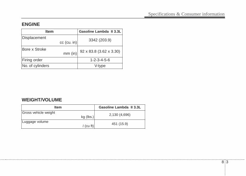
8 3
Specifications & Consumer information
ENGINE
WEIGHT/VOLUME
Item Gasoline Lambda II 3.3L
Gross vehicle weight kg (lbs.)
2,130 (4,696)
Luggage volume l (cu ft)
451 (15.9)
Item Gasoline Lambda II 3.3L
Displacementcc (cu. in)
3342 (203.9)
Bore x Strokemm (in) 92 x 83.8 (3.62 x 3.30)
Firing order 1-2-3-4-5-6
No. of cylinders V-type
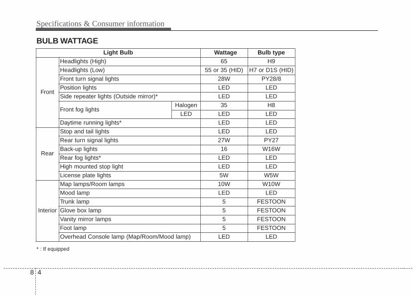
Specifications & Consumer information
48
BULB WATTAGE
* : If equipped
Light Bulb Wattage Bulb type
Front
Headlights (High) 65 H9
Headlights (Low) 55 or 35 (HID) H7 or D1S (HID)
Front turn signal lights 28W PY28/8
Position lights LED LED
Side repeater lights (Outside mirror)* LED LED
Front fog lightsHalogen 35 H8
LED LED LED
Daytime running lights* LED LED
Rear
Stop and tail lights LED LED
Rear turn signal lights 27W PY27
Back-up lights 16 W16W
Rear fog lights* LED LED
High mounted stop light LED LED
License plate lights 5W W5W
Interior
Map lamps/Room lamps 10W W10W
Mood lamp LED LED
Trunk lamp 5 FESTOON
Glove box lamp 5 FESTOON
Vanity mirror lamps 5 FESTOON
Foot lamp 5 FESTOON
Overhead Console lamp (Map/Room/Mood lamp) LED LED
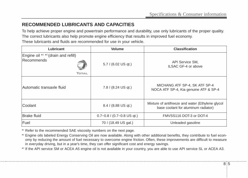
8 5
Specifications & Consumer information
RECOMMENDED LUBRICANTS AND CAPACITIES
*1 Refer to the recommended SAE viscosity numbers on the next page.*2 Engine oils labeled Energy Conserving Oil are now available. Along with other additional benefits, they contribute to fuel econ-
omy by reducing the amount of fuel necessary to overcome engine friction. Often, these improvements are difficult to measurein everyday driving, but in a year’s time, they can offer significant cost and energy savings.
*3 If the API service SM or ACEA A5 engine oil is not available in your country, you are able to use API service SL or ACEA A3.
To help achieve proper engine and powertrain performance and durability, use only lubricants of the proper quality.The correct lubricants also help promote engine efficiency that results in improved fuel economy.These lubricants and fluids are recommended for use in your vehicle.
Lubricant Volume Classification
Engine oil *1 *2 (drain and refill) Recommends
5.7 l (6.02 US qt.)API Service SM,
ILSAC GF-4 or above
Automatic transaxle fluid 7.8 l (8.24 US qt.)MICHANG ATF SP-4, SK ATF SP-4
NOCA ATF SP-4, Kia genuine ATF & SP-4
Coolant 8.4 l (8.88 US qt.)Mixture of antifreeze and water (Ethylene glycol
base coolant for aluminum radiator)
Brake fluid 0.7~0.8 l (0.7~0.8 US qt.) FMVSS116 DOT-3 or DOT-4
Fuel 70 l (18.49 US gal.) Unleaded gasoline
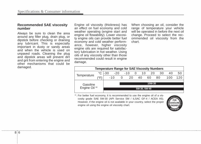
Specifications & Consumer information
68
Recommended SAE viscositynumberAlways be sure to clean the areaaround any filler plug, drain plug, ordipstick before checking or drainingany lubricant. This is especiallyimportant in dusty or sandy areasand when the vehicle is used onunpaved roads. Cleaning the plugand dipstick areas will prevent dirtand grit from entering the engine andother mechanisms that could bedamaged.
Engine oil viscosity (thickness) hasan effect on fuel economy and coldweather operating (engine start andengine oil flowability). Lower viscosi-ty engine oils can provide better fueleconomy and cold weather perform-ance, however, higher viscosityengine oils are required for satisfac-tory lubrication in hot weather. Usingoils of any viscosity other than thoserecommended could result in enginedamage.
When choosing an oil, consider therange of temperature your vehiclewill be operated in before the next oilchange. Proceed to select the rec-ommended oil viscosity from thechart.
Temperature Range for SAE Viscosity Numbers
Temperature
Gasoline Engine Oil *1
°C(°F)
-30 -20 -10 0 10 20 30 40 50-10 0 20 40 60 80 100 120
*1. For better fuel economy, it is recommended to use the engine oil of a vis-cosity grade SAE 5W-30 (API Service SM / ILSAC GF-4 / ACEA A5).However, if the engine oil is not available in your country, select the properengine oil using the engine oil viscosity chart.
10W-30
5W-30, 5W-40
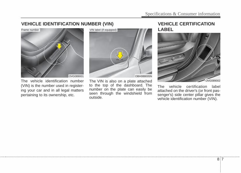
8 7
Specifications & Consumer information
The vehicle identification number(VIN) is the number used in register-ing your car and in all legal matterspertaining to its ownership, etc.
The VIN is also on a plate attachedto the top of the dashboard. Thenumber on the plate can easily beseen through the windshield fromoutside.
The vehicle certification labelattached on the driver’s (or front pas-senger’s) side center pillar gives thevehicle identification number (VIN).
VEHICLE IDENTIFICATION NUMBER (VIN)
OVG089001 OBH088005N
VIN label (if equipped)Frame number
OVG089002
VEHICLE CERTIFICATIONLABEL
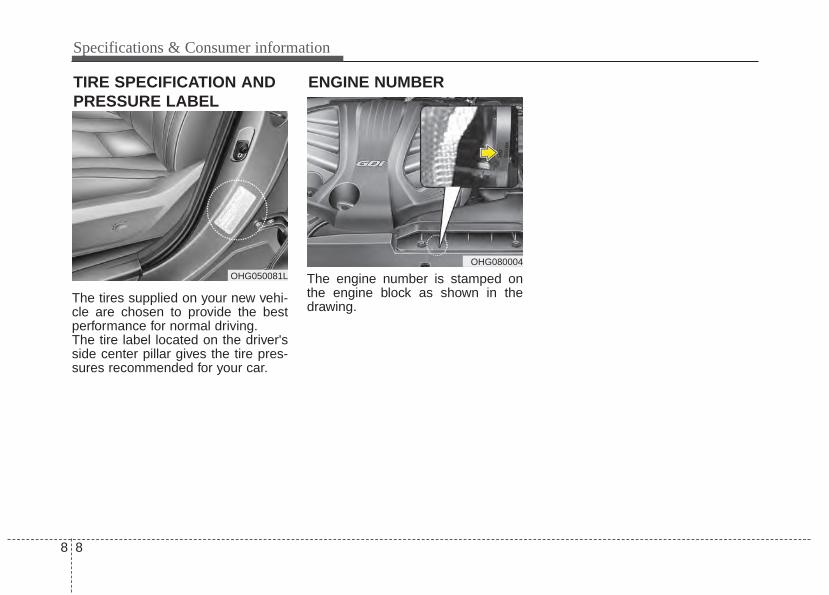
Specifications & Consumer information
88
The tires supplied on your new vehi-cle are chosen to provide the bestperformance for normal driving.The tire label located on the driver'sside center pillar gives the tire pres-sures recommended for your car.
The engine number is stamped onthe engine block as shown in thedrawing.
OHG050081L
OHG080004
ENGINE NUMBERTIRE SPECIFICATION ANDPRESSURE LABEL

Index
II
Index
2I
A/V Mode . . . . . . . . . . . . . . . . . . . . . . . . . . . . . . . . . . . 4-65Adaptive Front Lighting System (AFLS). . . . . . . . . . . 4-99Air bag warning label . . . . . . . . . . . . . . . . . . . . . . . . . . 3-54Air bag warning light . . . . . . . . . . . . . . . . . . . . . . . . . . 3-34Air bags. . . . . . . . . . . . . . . . . . . . . . . . . . . . . . . . . . . . . 3-31
Air bag warning label. . . . . . . . . . . . . . . . . . . . . . . . 3-54Air bag warning light . . . . . . . . . . . . . . . . . . . . . . . . 3-34Curtain air bag . . . . . . . . . . . . . . . . . . . . . . . . . . . . . 3-46Do not install a child restraint on the front
passenger’s seat. . . . . . . . . . . . . . . . . . . . . . . . . . . 3-33Driver's and passenger's front air bag . . . . . . . . . . . 3-43Inflation and non inflation conditions . . . . . . . . . . . 3-48Occupant detection system. . . . . . . . . . . . . . . . . . . . 3-37Operation . . . . . . . . . . . . . . . . . . . . . . . . . . . . . . . . . 3-32Side air bag. . . . . . . . . . . . . . . . . . . . . . . . . . . . . . . . 3-45SRS care . . . . . . . . . . . . . . . . . . . . . . . . . . . . . . . . . . 3-53SRS components and functions . . . . . . . . . . . . . . . . 3-35
Air cleaner . . . . . . . . . . . . . . . . . . . . . . . . . . . . . . . . . . 7-37Air ventilation seat . . . . . . . . . . . . . . . . . . . . . . . . . . . 4-134Air conditioning system . . . . . . . . . . . . . . . . . . . . . . . 4-113Alarm system . . . . . . . . . . . . . . . . . . . . . . . . . . . . . . . . 4-14Antenna. . . . . . . . . . . . . . . . . . . . . . . . . . . . . . . . . . . . 4-140Anti-lock brake system (ABS) . . . . . . . . . . . . . . . . . . . 5-28Appearance care
Exterior care . . . . . . . . . . . . . . . . . . . . . . . . . . . . . . . 7-74Interior care . . . . . . . . . . . . . . . . . . . . . . . . . . . . . . . 7-79
Armrest (rear) . . . . . . . . . . . . . . . . . . . . . . . . . . . . . . . . 3-12Audio system . . . . . . . . . . . . . . . . . . . . . . . . . . . . . . . 4-140
Antenna . . . . . . . . . . . . . . . . . . . . . . . . . . . . . . . . . 4-140Aux, USB port . . . . . . . . . . . . . . . . . . . . . . . . . . . . 4-142Steering wheel remote controller . . . . . . . . . . . . . . 4-141
Auto hold . . . . . . . . . . . . . . . . . . . . . . . . . . . . . . . . . . . 5-25Automatic climate control system . . . . . . . . . . . . . . . 4-113
Air conditioning . . . . . . . . . . . . . . . . . . . . . . . . . . . 4-123Automatic heating and air conditioning. . . . . . . . . 4-115Manual heating and air conditioning . . . . . . . . . . . 4-116
Automatic transaxle . . . . . . . . . . . . . . . . . . . . . . . . . . . 5-10Paddle shifter . . . . . . . . . . . . . . . . . . . . . . . . . . . . . . 5-13Shift lock system . . . . . . . . . . . . . . . . . . . . . . . . . . . 5-14Sports mode . . . . . . . . . . . . . . . . . . . . . . . . . . . . . . . 5-12
Automatic turn off function . . . . . . . . . . . . . . . . . . . . 4-107Aux, USB port . . . . . . . . . . . . . . . . . . . . . . . . . . . . . . 4-142
Battery. . . . . . . . . . . . . . . . . . . . . . . . . . . . . . . . . . . . . . 7-43Battery replacement . . . . . . . . . . . . . . . . . . . . . . . . . . . . 4-8Battery saver function. . . . . . . . . . . . . . . . . . . . . . . . . . 4-97Before driving . . . . . . . . . . . . . . . . . . . . . . . . . . . . . . . . . 5-3Blind spot detection system (BSD) . . . . . . . . . . . . . . . 5-59Brake system. . . . . . . . . . . . . . . . . . . . . . . . . . . . . . . . . 5-16
Anti-lock brake system (ABS). . . . . . . . . . . . . . . . . 5-28Auto hold . . . . . . . . . . . . . . . . . . . . . . . . . . . . . . . . . 5-25Electric parking brake (EPB) . . . . . . . . . . . . . . . . . . 5-19
A
B
I 3
Index
Electronic stability control (ESC) . . . . . . . . . . . . . . 5-30Hill-start assist control (HAC) . . . . . . . . . . . . . . . . . 5-33Parking brake . . . . . . . . . . . . . . . . . . . . . . . . . . . . . . 5-17Power brakes . . . . . . . . . . . . . . . . . . . . . . . . . . . . . . 5-16Vehicle stability management . . . . . . . . . . . . . . . . . 5-34
Brakes fluid. . . . . . . . . . . . . . . . . . . . . . . . . . . . . . . . . . 7-34Bulb wattage . . . . . . . . . . . . . . . . . . . . . . . . . . . . . . . . . . 8-4Button start/stop, see engine start/stop button . . . . . . . . 5-5
Camera (Rear view) . . . . . . . . . . . . . . . . . . . . . . . . . . . 4-94Capacities (Lubricants) . . . . . . . . . . . . . . . . . . . . . . . . . . 8-5Care
Exterior care . . . . . . . . . . . . . . . . . . . . . . . . . . . . . . . 7-74Interior care . . . . . . . . . . . . . . . . . . . . . . . . . . . . . . . 7-79Tire care . . . . . . . . . . . . . . . . . . . . . . . . . . . . . . . . . . 7-46
Center console storage . . . . . . . . . . . . . . . . . . . . . . . . 4-130Central door lock switch. . . . . . . . . . . . . . . . . . . . . . . . 4-19Checking the parking brake . . . . . . . . . . . . . . . . . . . . . 7-36Checking tire inflation pressure . . . . . . . . . . . . . . . . . . 7-47Child restraint system . . . . . . . . . . . . . . . . . . . . . . . . . . 3-24
Lower anchor system . . . . . . . . . . . . . . . . . . . . . . . . 3-29Seat belt . . . . . . . . . . . . . . . . . . . . . . . . . . . . . . . . . . 3-25Tether anchor system . . . . . . . . . . . . . . . . . . . . . . . . 3-28
Child-protector rear door lock . . . . . . . . . . . . . . . . . . . 4-20Climate control air filter . . . . . . . . . . . . . . . . . . . . . . . . 7-38Clock. . . . . . . . . . . . . . . . . . . . . . . . . . . . . . . . . . . . . . 4-136
Clothes hanger . . . . . . . . . . . . . . . . . . . . . . . . . . . . . . 4-137Combined instrument, see instrument cluster . . . . . . . 4-52Compact spare tire . . . . . . . . . . . . . . . . . . . . . . . . . . . . 6-20Compact spare tire replacement . . . . . . . . . . . . . . . . . . 7-51Coolant . . . . . . . . . . . . . . . . . . . . . . . . . . . . . . . . . . . . . 7-31Cooling fluid, see engine coolant . . . . . . . . . . . . . . . . . 7-31Crankcase emission control system . . . . . . . . . . . . . . . 7-81Cruise control system . . . . . . . . . . . . . . . . . . . . . . . . . . 5-37Cup holder . . . . . . . . . . . . . . . . . . . . . . . . . . . . . . . . . 4-132Curtain air bag . . . . . . . . . . . . . . . . . . . . . . . . . . . . . . . 3-46
Dashboard illumination, see instrument panelillumination . . . . . . . . . . . . . . . . . . . . . . . . . . . . . . . 4-53
Dashboard, see instrument cluster . . . . . . . . . . . . . . . . 4-52Daytime running light . . . . . . . . . . . . . . . . . . . . . . . . . 4-97Defogging (Windshield) . . . . . . . . . . . . . . . . . . . . . . . 4-126Defogging logic . . . . . . . . . . . . . . . . . . . . . . . . . . . . . 4-127Defroster (Rear window) . . . . . . . . . . . . . . . . . . . . . . 4-112Defrosting (Windshield) . . . . . . . . . . . . . . . . . . . . . . . 4-127Dimensions . . . . . . . . . . . . . . . . . . . . . . . . . . . . . . . . . . . 8-2Display illumination, see instrument panel
illumination . . . . . . . . . . . . . . . . . . . . . . . . . . . . . . . 4-53Displays, see instrument cluster . . . . . . . . . . . . . . . . . . 4-52Do not install a child restraint on the front
passenger’s seat . . . . . . . . . . . . . . . . . . . . . . . . . . . . 3-33Door courtesy lamp . . . . . . . . . . . . . . . . . . . . . . . . . . 4-110
CD
Index
4I
Door locks. . . . . . . . . . . . . . . . . . . . . . . . . . . . . . . . . . . 4-17Central door lock switch . . . . . . . . . . . . . . . . . . . . . 4-19Child-protector rear door lock . . . . . . . . . . . . . . . . . 4-20
Drinks holders, see cup holders . . . . . . . . . . . . . . . . . 4-132Driver position memory system . . . . . . . . . . . . . . . . . . . 3-7
Easy access function . . . . . . . . . . . . . . . . . . . . . . . . . 3-8Recalling positions . . . . . . . . . . . . . . . . . . . . . . . . . . . 3-8Storing positions. . . . . . . . . . . . . . . . . . . . . . . . . . . . . 3-7
Driver's and passenger's front air bag. . . . . . . . . . . . . . 3-43Driving at night. . . . . . . . . . . . . . . . . . . . . . . . . . . . . . . 5-67Driving in flooded areas . . . . . . . . . . . . . . . . . . . . . . . . 5-68Driving in the rain. . . . . . . . . . . . . . . . . . . . . . . . . . . . . 5-68DRL see Daytime running light . . . . . . . . . . . . . . . . . . 4-97
Economical operation . . . . . . . . . . . . . . . . . . . . . . . . . . 5-64Electric chromic mirror (ECM) . . . . . . . . . . . . . . . . . . 4-40Electric parking brake (EPB) . . . . . . . . . . . . . . . . . . . . 5-19Electric power steering . . . . . . . . . . . . . . . . . . . . . . . . . 4-37Electronic stability control (ESC) . . . . . . . . . . . . . . . . 5-30Emergency filler lid release . . . . . . . . . . . . . . . . . . . . . 4-31Emergency starting . . . . . . . . . . . . . . . . . . . . . . . . . . . . . 6-5
Jump starting . . . . . . . . . . . . . . . . . . . . . . . . . . . . . . . 6-5Emergency trunk safety release . . . . . . . . . . . . . . . . . . 4-22Emergency while driving . . . . . . . . . . . . . . . . . . . . . . . . 6-3Emission control system. . . . . . . . . . . . . . . . . . . . . . . . 7-81
Crankcase emission control system . . . . . . . . . . . . . 7-81
Evaporative emission control System . . . . . . . . . . . 7-81Exhaust emission control system . . . . . . . . . . . . . . . 7-82
Engine . . . . . . . . . . . . . . . . . . . . . . . . . . . . . . . . . . . . . . . 8-3Engine compartment. . . . . . . . . . . . . . . . . . . . . . . . . . . . 2-6Engine coolant . . . . . . . . . . . . . . . . . . . . . . . . . . . . . . . 7-31Engine Coolant Temperature guage . . . . . . . . . . . . . . . 4-55Engine number . . . . . . . . . . . . . . . . . . . . . . . . . . . . . . . . 8-8Engine oil . . . . . . . . . . . . . . . . . . . . . . . . . . . . . . . . . . . 7-29Engine overheats. . . . . . . . . . . . . . . . . . . . . . . . . . . . . . . 6-7Engine start/stop button . . . . . . . . . . . . . . . . . . . . . . . . . 5-5Engine will not start . . . . . . . . . . . . . . . . . . . . . . . . . . . . 6-4Evaporative emission control System. . . . . . . . . . . . . . 7-81Exhaust emission control system . . . . . . . . . . . . . . . . . 7-82Explanation of scheduled maintenance items . . . . . . . 7-25Exterior care . . . . . . . . . . . . . . . . . . . . . . . . . . . . . . . . . 7-74Exterior overview (Front) . . . . . . . . . . . . . . . . . . . . . . . . 2-2Exterior overview (Rear) . . . . . . . . . . . . . . . . . . . . . . . . 2-3
Flat tire . . . . . . . . . . . . . . . . . . . . . . . . . . . . . . . . . . . . . 6-14Changing tires . . . . . . . . . . . . . . . . . . . . . . . . . . . . . 6-15Compact spare tire . . . . . . . . . . . . . . . . . . . . . . . . . . 6-20Jack and tools . . . . . . . . . . . . . . . . . . . . . . . . . . . . . . 6-14Removing and storing the spare tire . . . . . . . . . . . . 6-15
Floor mat anchor(s) . . . . . . . . . . . . . . . . . . . . . . . . . . 4-137Fluid
Brakes fluid . . . . . . . . . . . . . . . . . . . . . . . . . . . . . . . 7-34
E
F
I 5
Index
Washer fluid . . . . . . . . . . . . . . . . . . . . . . . . . . . . . . . 7-35Fog light . . . . . . . . . . . . . . . . . . . . . . . . . . . . . . . . . . . 4-102Folding the outside rearview mirror . . . . . . . . . . . . . . . 4-50Front seat adjustment - power . . . . . . . . . . . . . . . . . . . . 3-4Fuel Economy. . . . . . . . . . . . . . . . . . . . . . . . . . . . . . . . 4-73Fuel filler lid . . . . . . . . . . . . . . . . . . . . . . . . . . . . . . . . . 4-29Fuel Gauge . . . . . . . . . . . . . . . . . . . . . . . . . . . . . . . . . . 4-55Fuel requirements . . . . . . . . . . . . . . . . . . . . . . . . . . . . . . 1-3Fuse switch . . . . . . . . . . . . . . . . . . . . . . . . . . . . . . . . . . 7-63Fuses . . . . . . . . . . . . . . . . . . . . . . . . . . . . . . . . . . . . . . . 7-61
Fuse switch. . . . . . . . . . . . . . . . . . . . . . . . . . . . . . . . 7-63Fuse/relay panel description. . . . . . . . . . . . . . . . . . . 7-65Instrument panel fuse . . . . . . . . . . . . . . . . . . . . . . . . 7-65Main fuse . . . . . . . . . . . . . . . . . . . . . . . . . . . . . . . . . 7-64Multi fuse . . . . . . . . . . . . . . . . . . . . . . . . . . . . . . . . . 7-64
Gauges . . . . . . . . . . . . . . . . . . . . . . . . . . . . . . . . . . . . . 4-54Glove box . . . . . . . . . . . . . . . . . . . . . . . . . . . . . . . . . . 4-130Glove box lamp. . . . . . . . . . . . . . . . . . . . . . . . . . . . . . 4-110Gross vehicle weight. . . . . . . . . . . . . . . . . . . . . . . . . . . . 8-3
Hazard warning flasher. . . . . . . . . . . . . . . . . . . . . . . . . 4-96Hazardous driving conditions . . . . . . . . . . . . . . . . . . . . 5-66Headlamp escort function. . . . . . . . . . . . . . . . . . . . . . . 4-97
Headlight leveling device . . . . . . . . . . . . . . . . . . . . . . 4-103Headrest(front) . . . . . . . . . . . . . . . . . . . . . . . . . . . . . . . . 3-9Headrest(rear) . . . . . . . . . . . . . . . . . . . . . . . . . . . . . . . . 3-11Heated steering wheel. . . . . . . . . . . . . . . . . . . . . . . . . . 4-39Heater . . . . . . . . . . . . . . . . . . . . . . . . . . . . . . . . . . . . . 4-113Height adjustment. . . . . . . . . . . . . . . . . . . . . . . . . . . . . 3-16High - beam operation . . . . . . . . . . . . . . . . . . . . . . . . 4-110Highway driving . . . . . . . . . . . . . . . . . . . . . . . . . . . . . . 5-69Hill-start assist control (HAC) . . . . . . . . . . . . . . . . . . . 5-33HomeLink system. . . . . . . . . . . . . . . . . . . . . . . . . . . . . 4-40Hood . . . . . . . . . . . . . . . . . . . . . . . . . . . . . . . . . . . . . . . 4-27Horn . . . . . . . . . . . . . . . . . . . . . . . . . . . . . . . . . . . . . . . 4-39How to use this manual . . . . . . . . . . . . . . . . . . . . . . . . . 1-2
Immobilizer system . . . . . . . . . . . . . . . . . . . . . . . . . . . 4-11Indicator light . . . . . . . . . . . . . . . . . . . . . . . . . . . . . . . . 4-86Inflation and non inflation conditions . . . . . . . . . . . . . 3-48Inside rearview mirror . . . . . . . . . . . . . . . . . . . . . . . . . 4-40Instrument cluster . . . . . . . . . . . . . . . . . . . . . . . . . . . . . 4-52
Gauges . . . . . . . . . . . . . . . . . . . . . . . . . . . . . . . . . . . 4-54Instrument panel illumination . . . . . . . . . . . . . . . . . 4-53LCD Display Control . . . . . . . . . . . . . . . . . . . . . . . . 4-53Transaxle Shift Indicator . . . . . . . . . . . . . . . . . . . . . 4-58
Instrument panel fuse . . . . . . . . . . . . . . . . . . . . . . . . . . 7-62Instrument panel overview . . . . . . . . . . . . . . . . . . . . . . . 2-5Interior care. . . . . . . . . . . . . . . . . . . . . . . . . . . . . . . . . . 7-79
G
H
I
Index
6I
Interior features. . . . . . . . . . . . . . . . . . . . . . . . . . . . . . 4-132Air ventilation seat . . . . . . . . . . . . . . . . . . . . . . . . . 4-134Clock . . . . . . . . . . . . . . . . . . . . . . . . . . . . . . . . . . . 4-136Cup holder . . . . . . . . . . . . . . . . . . . . . . . . . . . . . . . 4-132Floor mat anchor(s) . . . . . . . . . . . . . . . . . . . . . . . . 4-137Luggage net (holder) . . . . . . . . . . . . . . . . . . . . . . . 4-138Power outlet . . . . . . . . . . . . . . . . . . . . . . . . . . . . . . 4-135Rear curtain . . . . . . . . . . . . . . . . . . . . . . . . . . . . . . 4-139Seat warmer . . . . . . . . . . . . . . . . . . . . . . . . . . . . . . 4-133Sunvisor . . . . . . . . . . . . . . . . . . . . . . . . . . . . . . . . . 4-132
Interior light . . . . . . . . . . . . . . . . . . . . . . . . . . . . . . . . 4-107Automatic turn off function . . . . . . . . . . . . . . . . . . 4-107Door courtesy lamp . . . . . . . . . . . . . . . . . . . . . . . . 4-110Glove box lamp . . . . . . . . . . . . . . . . . . . . . . . . . . . 4-110Map lamp . . . . . . . . . . . . . . . . . . . . . . . . . . . . . . . . 4-107Map lamp/Room lamp/Mood lamp . . . . . . . . . . . . 4-109Room lamp . . . . . . . . . . . . . . . . . . . . . . . . . . . . . . . 4-108Trunk room lamp . . . . . . . . . . . . . . . . . . . . . . . . . . 4-110Vanity mirror lamp . . . . . . . . . . . . . . . . . . . . . . . . . 4-111
Interior overview. . . . . . . . . . . . . . . . . . . . . . . . . . . . . . . 2-4
Jack and tools . . . . . . . . . . . . . . . . . . . . . . . . . . . . . . . . 6-14Jump starting. . . . . . . . . . . . . . . . . . . . . . . . . . . . . . . . . . 6-5
LabelAir bag warning label. . . . . . . . . . . . . . . . . . . . . . . . 3-54Tire sidewall labeling . . . . . . . . . . . . . . . . . . . . . . . . 7-52Tire specification and pressure label . . . . . . . . . . . . . 8-8
Lane departure warning system (LDWS). . . . . . . . . . . 5-55LCD display . . . . . . . . . . . . . . . . . . . . . . . . . . . . . . . . . 4-59
A/V Mode. . . . . . . . . . . . . . . . . . . . . . . . . . . . . . . . . 4-65LCD modes . . . . . . . . . . . . . . . . . . . . . . . . . . . . . . . 4-59Service Mode . . . . . . . . . . . . . . . . . . . . . . . . . . . . . . 4-60Turn By Turn Mode . . . . . . . . . . . . . . . . . . . . . . . . . 4-65User Settings Mode . . . . . . . . . . . . . . . . . . . . . . . . . 4-62Warning Messages . . . . . . . . . . . . . . . . . . . . . . . . . . 4-66
LCD Display Control . . . . . . . . . . . . . . . . . . . . . . . . . . 4-53LCD modes. . . . . . . . . . . . . . . . . . . . . . . . . . . . . . . . . . 4-59Lighting. . . . . . . . . . . . . . . . . . . . . . . . . . . . . . . . . . . . . 4-97
Battery saver function . . . . . . . . . . . . . . . . . . . . . . . 4-97Daytime running light . . . . . . . . . . . . . . . . . . . . . . . 4-97Front fog light . . . . . . . . . . . . . . . . . . . . . . . . . . . . 4-102Headlamp escort function . . . . . . . . . . . . . . . . . . . . 4-97Headlight leveling device. . . . . . . . . . . . . . . . . . . . 4-103High - beam operation . . . . . . . . . . . . . . . . . . . . . . 4-100Lighting control . . . . . . . . . . . . . . . . . . . . . . . . . . . . 4-98Turn signals and lane change signals. . . . . . . . . . . 4-101
Lighting control . . . . . . . . . . . . . . . . . . . . . . . . . . . . . . 4-98Adaptive Front Lighting System (AFLS) . . . . . . . . 4-99Autolight. . . . . . . . . . . . . . . . . . . . . . . . . . . . . . . . . . 4-99
J
L
I 7
Index
Lower anchor system . . . . . . . . . . . . . . . . . . . . . . . . . . 3-29Lubricants and capacities . . . . . . . . . . . . . . . . . . . . . . . . 8-5Luggage net (holder) . . . . . . . . . . . . . . . . . . . . . . . . . 4-138Luggage volume . . . . . . . . . . . . . . . . . . . . . . . . . . . . . . . 8-3
Main fuse . . . . . . . . . . . . . . . . . . . . . . . . . . . . . . . . . . . 7-64Maintenance
Explanation of scheduled maintenance items . . . . . 7-25Maintenance services . . . . . . . . . . . . . . . . . . . . . . . . . 7-4Owner maintenance . . . . . . . . . . . . . . . . . . . . . . . . . . 7-6Scheduled maintenance service . . . . . . . . . . . . . . . . . 7-8Tire maintenance . . . . . . . . . . . . . . . . . . . . . . . . . . . 7-51
Maintenance schedule . . . . . . . . . . . . . . . . . . . . . . . . . . 7-8Maintenance services . . . . . . . . . . . . . . . . . . . . . . . . . . . 7-4Map lamp . . . . . . . . . . . . . . . . . . . . . . . . . . . . . . . . . . 4-107Map lamp/Room lamp/Mood lamp . . . . . . . . . . . . . . 4-109Mirrors . . . . . . . . . . . . . . . . . . . . . . . . . . . . . . . . . . . . . 4-40
Electric chromic mirror (ECM) . . . . . . . . . . . . . . . . 4-40HomeLink system . . . . . . . . . . . . . . . . . . . . . . . . . . 4-40Inside rearview mirror . . . . . . . . . . . . . . . . . . . . . . . 4-40Outside rearview mirror . . . . . . . . . . . . . . . . . . . . . . 4-48
Moonroof, see panoramic sunroof . . . . . . . . . . . . . . . . 4-32Multi fuse . . . . . . . . . . . . . . . . . . . . . . . . . . . . . . . . . . . 7-64
Occupant detection system . . . . . . . . . . . . . . . . . . . . . . 3-37Odometer . . . . . . . . . . . . . . . . . . . . . . . . . . . . . . . . . . . 4-57Oil (Engine) . . . . . . . . . . . . . . . . . . . . . . . . . . . . . . . . . 7-29Outside rearview mirror . . . . . . . . . . . . . . . . . . . . . . . . 4-48
Folding the outside rearview mirror. . . . . . . . . . . . . 4-50Reverse parking aid function . . . . . . . . . . . . . . . . . . 4-50
Outside Temperature Gauge . . . . . . . . . . . . . . . . . . . . . 4-57Overheats . . . . . . . . . . . . . . . . . . . . . . . . . . . . . . . . . . . . 6-7Owner maintenance . . . . . . . . . . . . . . . . . . . . . . . . . . . . 7-6
Paddle shifter . . . . . . . . . . . . . . . . . . . . . . . . . . . . . . . . 5-13Panoramic sunroof . . . . . . . . . . . . . . . . . . . . . . . . . . . . 4-32Parking brake . . . . . . . . . . . . . . . . . . . . . . . . . . . . . . . . 5-17
Checking the parking brake . . . . . . . . . . . . . . . . . . . 7-36Power brakes. . . . . . . . . . . . . . . . . . . . . . . . . . . . . . . . . 5-16Power outlet . . . . . . . . . . . . . . . . . . . . . . . . . . . . . . . . 4-135Power window lock button . . . . . . . . . . . . . . . . . . . . . . 4-26Pre-tensioner seat belt. . . . . . . . . . . . . . . . . . . . . . . . . . 3-18
O
P
M
Index
8I
Rear curtain. . . . . . . . . . . . . . . . . . . . . . . . . . . . . . . . . 4-139Rear parking assist system . . . . . . . . . . . . . . . . . . . . . . 4-90Rear seat adjustment . . . . . . . . . . . . . . . . . . . . . . . . . . . 3-11Rear view camera . . . . . . . . . . . . . . . . . . . . . . . . . . . . . 4-94Recommended cold tire inflation pressures . . . . . . . . . 7-46Recommended lubricants and capacities . . . . . . . . . . . . 8-5
Recommended SAE viscosity number. . . . . . . . . . . . 8-6Record your key number . . . . . . . . . . . . . . . . . . . . . . . . 4-4Remote keyless entry system operations . . . . . . . . . . . . 4-6Reverse parking aid function . . . . . . . . . . . . . . . . . . . . 4-50Road warning . . . . . . . . . . . . . . . . . . . . . . . . . . . . . . . . . 6-2Rocking the vehicle . . . . . . . . . . . . . . . . . . . . . . . . . . . 5-66Room lamp . . . . . . . . . . . . . . . . . . . . . . . . . . . . . . . . . 4-108Rotation (Tire) . . . . . . . . . . . . . . . . . . . . . . . . . . . . . . . 7-50
Scheduled maintenance service . . . . . . . . . . . . . . . . . . . 7-8Seat belt Precautions. . . . . . . . . . . . . . . . . . . . . . . . . . . 3-21Seat belt restraint system . . . . . . . . . . . . . . . . . . . . . . . 3-13Seat belt warning . . . . . . . . . . . . . . . . . . . . . . . . . . . . . 3-14Seat belts . . . . . . . . . . . . . . . . . . . . . . . . . . . . . . . . . . . . 3-13
3 point system seat belt . . . . . . . . . . . . . . . . . . . . . . 3-15Height adjustment . . . . . . . . . . . . . . . . . . . . . . . . . . 3-16Pre-tensioner seat belt . . . . . . . . . . . . . . . . . . . . . . . 3-18Seat belt Precautions . . . . . . . . . . . . . . . . . . . . . . . . 3-21
Seat belt restraint system . . . . . . . . . . . . . . . . . . . . . 3-13Seat belt warning . . . . . . . . . . . . . . . . . . . . . . . . . . . 3-14
Seat warmer . . . . . . . . . . . . . . . . . . . . . . . . . . . . . . . . 4-133Seatback pocket . . . . . . . . . . . . . . . . . . . . . . . . . . . . . . 3-10Seats . . . . . . . . . . . . . . . . . . . . . . . . . . . . . . . . . . . . . . . . 3-2
Armrest (rear). . . . . . . . . . . . . . . . . . . . . . . . . . . . . . 3-12Front seat adjustment - power . . . . . . . . . . . . . . . . . . 3-4Headrest(front) . . . . . . . . . . . . . . . . . . . . . . . . . . . . . . 3-9Headrest(rear). . . . . . . . . . . . . . . . . . . . . . . . . . . . . . 3-11Rear seat adjustment . . . . . . . . . . . . . . . . . . . . . . . . 3-11Seatback pocket . . . . . . . . . . . . . . . . . . . . . . . . . . . . 3-10
Service Mode . . . . . . . . . . . . . . . . . . . . . . . . . . . . . . . . 4-60Shift lock system . . . . . . . . . . . . . . . . . . . . . . . . . . . . . 5-14Side air bag . . . . . . . . . . . . . . . . . . . . . . . . . . . . . . . . . . 3-45Smart cruise control system . . . . . . . . . . . . . . . . . . . . . 5-41Smart key . . . . . . . . . . . . . . . . . . . . . . . . . . . . . . . . . . . . 4-4
Battery replacement . . . . . . . . . . . . . . . . . . . . . . . . . . 4-8Immobilizer system . . . . . . . . . . . . . . . . . . . . . . . . . 4-11Record your key number . . . . . . . . . . . . . . . . . . . . . . 4-4Remote keyless entry system operations . . . . . . . . . . 4-6Smart key functions . . . . . . . . . . . . . . . . . . . . . . . . . . 4-4Smart key precautions . . . . . . . . . . . . . . . . . . . . . . . . 4-5Transmitter precautions . . . . . . . . . . . . . . . . . . . . . . . 4-7
Smart key functions . . . . . . . . . . . . . . . . . . . . . . . . . . . . 4-4Smart key precautions. . . . . . . . . . . . . . . . . . . . . . . . . . . 4-5Smooth cornering . . . . . . . . . . . . . . . . . . . . . . . . . . . . . 5-67Snow tires . . . . . . . . . . . . . . . . . . . . . . . . . . . . . . . . . . . 5-70
R
S
I 9
Index
Spare tireChanging tires . . . . . . . . . . . . . . . . . . . . . . . . . . . . . 6-15Compact spare tire . . . . . . . . . . . . . . . . . . . . . . . . . . 6-20Compact spare tire replacement. . . . . . . . . . . . . . . . 7-51Removing and storing the spare tire . . . . . . . . . . . . 6-15
Special driving conditions . . . . . . . . . . . . . . . . . . . . . . 5-66Driving at night . . . . . . . . . . . . . . . . . . . . . . . . . . . . 5-67Driving in flooded areas. . . . . . . . . . . . . . . . . . . . . . 5-68Driving in the rain . . . . . . . . . . . . . . . . . . . . . . . . . . 5-68Hazardous driving conditions . . . . . . . . . . . . . . . . . 5-66Highway driving. . . . . . . . . . . . . . . . . . . . . . . . . . . . 5-69Rocking the vehicle . . . . . . . . . . . . . . . . . . . . . . . . . 5-66Smooth cornering . . . . . . . . . . . . . . . . . . . . . . . . . . . 5-67
Speedometer . . . . . . . . . . . . . . . . . . . . . . . . . . . . . . . . . 4-54Sports mode . . . . . . . . . . . . . . . . . . . . . . . . . . . . . . . . . 5-12SRS care . . . . . . . . . . . . . . . . . . . . . . . . . . . . . . . . . . . . 3-53SRS components and functions . . . . . . . . . . . . . . . . . . 3-35Starting difficulties, see engine will not start . . . . . . . . . 6-4Steering wheel . . . . . . . . . . . . . . . . . . . . . . . . . . . . . . . 4-37
Electric power steering. . . . . . . . . . . . . . . . . . . . . . . 4-37Heated steering wheel . . . . . . . . . . . . . . . . . . . . . . . 4-39Horn . . . . . . . . . . . . . . . . . . . . . . . . . . . . . . . . . . . . . 4-39Tilt and telescopic steering. . . . . . . . . . . . . . . . . . . . 4-38
Steering wheel remote controller . . . . . . . . . . . . . . . . 4-141Storage compartment . . . . . . . . . . . . . . . . . . . . . . . . . 4-130
Center console storage . . . . . . . . . . . . . . . . . . . . . . 4-130Glove box . . . . . . . . . . . . . . . . . . . . . . . . . . . . . . . . 4-130Sunglass holder . . . . . . . . . . . . . . . . . . . . . . . . . . . 4-131
Sunglass holder. . . . . . . . . . . . . . . . . . . . . . . . . . . . . . 4-131Sunvisor . . . . . . . . . . . . . . . . . . . . . . . . . . . . . . . . . . . 4-132
Tachometer . . . . . . . . . . . . . . . . . . . . . . . . . . . . . . . . . . 4-54Tether anchor system . . . . . . . . . . . . . . . . . . . . . . . . . . 3-28Theft-alarm system . . . . . . . . . . . . . . . . . . . . . . . . . . . . 4-14Tilt and telescopic steering . . . . . . . . . . . . . . . . . . . . . . 4-38Tire and wheels. . . . . . . . . . . . . . . . . . . . . . . . . . . . . . . . 8-2Tire pressure monitoring system . . . . . . . . . . . . . . . . . . 6-8Tire rotation . . . . . . . . . . . . . . . . . . . . . . . . . . . . . . . . . 7-48Tire specification and pressure label . . . . . . . . . . . . . . . 8-8
Checking tire inflation pressure . . . . . . . . . . . . . . . . 7-47Compact spare tire replacement. . . . . . . . . . . . . . . . 7-51Recommended cold tire inflation pressures. . . . . . . 7-46Tire care . . . . . . . . . . . . . . . . . . . . . . . . . . . . . . . . . . 7-46Tire maintenance . . . . . . . . . . . . . . . . . . . . . . . . . . . 7-51Tire replacement. . . . . . . . . . . . . . . . . . . . . . . . . . . . 7-50Tire rotation . . . . . . . . . . . . . . . . . . . . . . . . . . . . . . . 7-48Tire sidewall labeling . . . . . . . . . . . . . . . . . . . . . . . . 7-52Tire traction . . . . . . . . . . . . . . . . . . . . . . . . . . . . . . . 7-51Wheel alignment and tire balance . . . . . . . . . . . . . . 7-49Wheel replacement. . . . . . . . . . . . . . . . . . . . . . . . . . 7-51
Towing . . . . . . . . . . . . . . . . . . . . . . . . . . . . . . . . . . . . . 6-22Transaxle
Automatic transaxle . . . . . . . . . . . . . . . . . . . . . . . . . 5-10Transaxle Shift Indicator . . . . . . . . . . . . . . . . . . . . . . . 4-58
T
Index
10I
Transmitter precautions . . . . . . . . . . . . . . . . . . . . . . . . . 4-7Trip A/B . . . . . . . . . . . . . . . . . . . . . . . . . . . . . . . . . . . . 4-75Trip computer . . . . . . . . . . . . . . . . . . . . . . . . . . . . . . . . 4-73
Fuel Economy . . . . . . . . . . . . . . . . . . . . . . . . . . . . . 4-73Trip A/B . . . . . . . . . . . . . . . . . . . . . . . . . . . . . . . . . . 4-75
Trunk. . . . . . . . . . . . . . . . . . . . . . . . . . . . . . . . . . . . . . . 4-21Emergency filler lid release . . . . . . . . . . . . . . . . . . . 4-31Emergency trunk safety release . . . . . . . . . . . . . . . . 4-22
Trunk room lamp . . . . . . . . . . . . . . . . . . . . . . . . . . . . 4-110Turn By Turn Mode . . . . . . . . . . . . . . . . . . . . . . . . . . . 4-65Turn signals and lane change signals . . . . . . . . . . . . . 4-101
User Settings Mode . . . . . . . . . . . . . . . . . . . . . . . . . . . 4-62
Vanity mirror lamp . . . . . . . . . . . . . . . . . . . . . . . . . . . 4-111Vehicle break-in process . . . . . . . . . . . . . . . . . . . . . . . . . 1-5Vehicle identification number (VIN) . . . . . . . . . . . . . . . 8-7Vehicle load limit . . . . . . . . . . . . . . . . . . . . . . . . . . . . . 5-73Vehicle stability management . . . . . . . . . . . . . . . . . . . . 5-34Vehicle weight . . . . . . . . . . . . . . . . . . . . . . . . . . . . . . . 5-78
Warning light . . . . . . . . . . . . . . . . . . . . . . . . . . . . . . . . 4-77Warning Messages . . . . . . . . . . . . . . . . . . . . . . . . . . . . 4-66Washer fluid . . . . . . . . . . . . . . . . . . . . . . . . . . . . . . . . . 7-35Welcome system . . . . . . . . . . . . . . . . . . . . . . . . . . . . . . 4-95Wheel alignment and tire balance . . . . . . . . . . . . . . . . 7-49Wheel replacement . . . . . . . . . . . . . . . . . . . . . . . . . . . . 7-51Windows . . . . . . . . . . . . . . . . . . . . . . . . . . . . . . . . . . . . 4-23
Power window lock button. . . . . . . . . . . . . . . . . . . . 4-26Windshield defrosting and defogging. . . . . . . . . . . . . 4-126Windshield washers . . . . . . . . . . . . . . . . . . . . . . . . . . 4-106Windshield wipers . . . . . . . . . . . . . . . . . . . . . . . . . . . 4-104Winter driving. . . . . . . . . . . . . . . . . . . . . . . . . . . . . . . . 5-70
Snow tires. . . . . . . . . . . . . . . . . . . . . . . . . . . . . . . . . 5-70Wiper blades . . . . . . . . . . . . . . . . . . . . . . . . . . . . . . . . . 7-39Wipers and washers . . . . . . . . . . . . . . . . . . . . . . . . . . 4-104
Windshield washers . . . . . . . . . . . . . . . . . . . . . . . . 4-106Windshield wipers . . . . . . . . . . . . . . . . . . . . . . . . . 4-104
3 point system seat belt . . . . . . . . . . . . . . . . . . . . . . . . 3-15
U
V
W
ETC