Embed Size (px)
Citation preview

Kia, THE COMPANYThank you for becoming the owner of a new Kia vehicle.As a global car manufacturer focused on building high-quality, valuefor money prices, Kia Motors is dedicated to providing you with acustomer service experience that exceeds your expectations.
All information contained in this Owner’s Manual is accurate at thetime of publication. However, Kia reserves the right to make changesat any time so that our policy of continual product improvement canbe carried out.
This manual applies to all Kia models and includes descriptions andexplanations of optional as well as standard equipment. As a result,you may encounter material in this manual that is not applicable toyour specific Kia vehicle.
Drive safely and enjoy your Kia!

i
Thank you for choosing a Kia vehicle.When you require service, remember that your Kia Dealerknows your vehicle best. Your dealer has factory-trained tech-nicians, recommended special tools, genuine Kia replacementparts and is dedicated to your complete satisfaction.Because subsequent owners require this important informationas well, this publication should remain with the vehicle if it issold.This manual will familiarize you with operational, mainte-nance and safety information about your new vehicle. It is sup-plemented by a Warranty and Consumer Information manualthat provides important information on all warranties regardingyour vehicle.We urge you to read these publications carefully and follow therecommendations to help assure enjoyable and safe operationof your new vehicle.Kia offers a great variety of options, components and featuresfor its various models. Therefore, some of the equipmentdescribed in this manual, along with the various illustrations,may not be applicable to your particular vehicle.
The information and specifications provided in this manualwere accurate at the time of printing. Kia reserves the right todiscontinue or change specifications or design at any timewithout notice and without incurring any obligation. If youhave questions, always check with your Kia dealer.We assure you of our continuing interest in your motoringpleasure and satisfaction in your Kia vehicle.
© 2011 Kia Canada Inc.All rights reserved. Reproduction by any means, electronic ormechanical, including photocopying, recording, or by anyinformation storage and retrieval system or translation inwhole or part is not permitted without written authorizationfrom Kia Canada Inc..Printed in Korea
Foreword

ii
1
2
3
4
5
6
7
Introduction
Your vehicle at a glance
Safety features of your vehicle
Features of your vehicle
Driving your vehicle
What to do in an emergency
Maintenance
table of contents
8
I
Specifications & Consumer information
Index

IIndex

Index
2I
Active eco system ··························································5-41Air bag warning label ····················································3-53Air bag warning light·····················································3-33Air bags··········································································3-30
Air bag warning label ··················································3-53Air bag warning light ··················································3-33Curtain air bag ·····························································3-45Driver's and passenger's front air bag··························3-41Occupant detection system··········································3-36Side impact air bag······················································3-44SRS components and functions···································3-33
Air cleaner ·····································································7-31Antenna (Roof) ····························································4-102Anti-lock brake system (ABS) ······································5-24Appearance care·····························································7-60
Exterior care ································································7-60Interior care ·································································7-64
Ashtray···········································································4-96Audio system ·······························································4-102
Roof antenna······························································4-102Steering wheel audio control·····································4-103
Automatic transaxle ·······················································5-15Shift lock ·····································································5-19Sports mode·································································5-17
Automatic transaxle fluid ··············································7-30Aux, USB and iPod port··············································4-104
Base curb weight ···························································5-56Battery············································································7-34Battery saver function····················································4-70Before driving ··································································5-3Bottle holders, see cup holders······································4-97Brake system··································································5-21
Anti-lock brake system (ABS) ····································5-24Electronic stability program (ESC) ·····························5-25Hill-start assist control·················································5-28Parking brake·······························································5-22Power brakes································································5-21Vehicle stability management······································5-29
Brakes/clutch fluid·························································7-29Bulb wattage ····································································8-3
Calendar ·······································································4-100Capacities (Lubricants) ····················································8-5Car option ······································································4-50Care
Exterior care ································································7-60Interior care ·································································7-64Tire care·······································································7-37
A B
C

I 3
Index
Cargo capacity ·······························································5-52Cargo weight··································································5-56Center console storage···················································4-92Central door lock switch················································4-17Certification label ···················································5-54, 8-7Changing tires································································6-14Checking tire inflation pressure·····································7-38Child restraint system ····················································3-22
Lower anchor·······························································3-27Seat belt ·······································································3-24Tether anchor system···················································3-26
Child-protector rear door lock ·······································4-18Cigarette lighter ·····························································4-96Climate control air filter·······································4-81, 7-32Clock (Digital) ·······························································4-99Clothes hanger ·····························································4-100Combined instrument, see instrument cluster ···············4-41Compact spare tire ·························································6-19Compact spare tire replacement ····································7-41Coolant···········································································7-26Cooling fluid, see engine coolant ··································7-26Crankcase emission control system·······························7-66Cruise control system ····················································5-32Cup holder ·····································································4-97Curtain air bag ·······························································3-45
Dashboard illumination, see instrument panel illumination··································································4-42
Dashboard, see instrument cluster ·································4-41Defogging (Windshield) ················································4-90Defogging logic (Windshield) ·······································4-91Defroster (Rear window) ···············································4-80Defrosting (Windshield) ················································4-90Digital clock···································································4-99Dimensions ······································································8-2Display illumination, see instrument panel
illumination··································································4-42Displays, see instrument cluster ····································4-41Door locks······································································4-15
Central door lock switch ·············································4-17Child-protector rear door lock·····································4-18
Drinks holders, see cup holders·····································4-97Driver's 3-point seat belt················································3-14Driver's and passenger's front air bag····························3-41Driving at night······························································5-45Driving in flooded areas ················································5-46Driving in the rain··························································5-46
D
Index
4I
Economical operation ····················································5-42Electric power steering ··················································4-35Electronic stability program (ESC) ·······························5-25Emergency starting ··························································6-4
Jump starting ·································································6-4Push starting ··································································6-6
Emergency while driving·················································6-2Emission control system················································7-66
Crankcase emission control system·····························7-66Evaporative emission control System ·························7-66Exhaust emission control system ································7-66
Engine ··············································································8-2Engine compartment························································2-4Engine compartment panel fuse ····································7-58Engine coolant ·······························································7-26Engine coolcant temperature gauge·······························4-43Engine number·································································8-8Engine oil·······································································7-25Engine overheats······························································6-7Engine start/stop button ···················································5-6Engine will not start·························································6-3Evaporative emission control System····························7-66Exhaust emission control system···································7-66Explanation of scheduled maintenance items ···············7-22Exterior care···································································7-60
Flat tire (with spare tire) ················································6-13Jack and tools ······························································6-13Changing tires······························································6-14Compact spare tire·······················································6-19Removing and storing the spare tire····························6-14
Flat tire (with tire mobility kit) ·····································6-21Floor mat anchor(s) ·····················································4-101Fluid
Automatic transaxle fluid ············································7-30Brakes/clutch fluid·······················································7-29Washer fluid·································································7-30
Folding the outside rearviwe mirror ······························4-40Folding the rear seat ······················································3-10Front passenger and rear seat belt ·································3-16Front seat adjustment·······················································3-4Fuel filler lid ··································································4-28Fuel gauge······································································4-43Fuel requirements ····························································1-3Fuses ··············································································7-50
Engine compartment panel fuse ··································7-52Fuse/relay panel description········································7-54Instrument panel fuse ··················································7-51Memory fuse································································7-51Multi fuse ····································································7-53
FE

I 5
Index
GaugeEngine coolant temperature gauge ······························4-42Fuel gauge ···································································4-43
GAW (Gross axle weight) ·············································5-56GAWR (Gross axle weight rating) ································5-56Glove box·······································································4-92GVW (Gross vehicle weight) ········································5-56GVWR (Gross vehicle weight rating) ···························5-56
Hazard warning flasher··················································4-70Hazardous driving conditions ········································5-44Headrest(front)·································································3-5Headrest(rear) ··································································3-9Hight adjustment····························································3-15Highway driving ····························································5-47Hill-start assist control···················································5-28Hood···············································································4-26Horn ···············································································4-37How to use this manual ···················································1-2
Idle stop and go system ·················································5-37Immobilizer system ·······················································4-10Indicator symbols on the instrument cluster ···················1-5Indicators and warnings·················································4-53Inside rearview mirror ···················································4-38Instrument cluster ··························································4-41
Car option ····································································4-50Engine coolant temperature gauge ······························4-43Fuel gauge ···································································4-43Instrument panel illumination ·····································4-42LCD display warning ··················································4-63Maintenance ································································4-51Odometer ·····································································4-44Speedometer ································································4-42Tachometer ··································································4-42Trip computer ······························································4-45User settings ································································4-49Warning and indicators················································4-53
Instrument panel fuse·····················································7-55Instrument panel illumination········································4-42Instrument panel overview···············································2-3Interior care····································································7-64Interior features······························································4-96
Ashtray ········································································4-96Aux, USB and iPod port············································4-104Cigarette lighter ···························································4-96
G
H
I

Index
6I
Clothes hanger ···························································4-100Cup holder ···································································4-97Digital clock and calendar···········································4-99Floor mat anchor(s) ···················································4-101Power outlet·································································4-98Shopping bag holder····················································4-99Sliding armrest ····························································4-97Sunvisor ·······································································4-98
Interior light ···································································4-78Interior overview······························································2-2ISG system·····································································5-37
Jack and tools·································································6-13Jump starting····································································6-4
Key positions ···································································5-4Keys ·················································································4-2
Immobilizer key···························································4-10Remote(or Smart) key battery replacement ················4-97
LabelAir bag warning label ··················································3-53Refrigerant label ····························································8-8Tire sidewall labeling ··················································7-42Tire specification and pressure label ·····························8-8Vehicle certification label ··············································8-7
LCD display warning·····················································4-63Lighting··········································································4-70
Battery saver function··················································4-70Lower anchor ·································································3-27Lubricants and capacities·················································8-5Luggage net ···································································4-93Luggage tray ··································································4-94
Maintenance···································································4-51Explanation of scheduled maintenance items ·············7-22Maintenance services·····················································7-3Maintenance under severe usage conditions ···············7-20Normal maintenance schedule·······································7-8Owner maintenance ·······················································7-5Scheduled maintenance service·····································7-7Tire maintenance ·························································7-42
J
L
MK

I 7
Index
Maintenance schedule······················································7-7Maintenance under severe usage conditions ·················7-20
Normal maintenance schedule·······································7-8Maintenance services·······················································7-3Manual climate control system······································4-81
Air conditioning ··························································4-86Climate control air filter ··············································4-89Heating and air conditioning ·······································4-82
Manual transaxle····························································5-12Memory fuse··································································7-51Mirrors ···········································································4-38
Day/night rearview mirror···········································4-38Folding the outside rearviwe mirror····························4-40Inside rearview mirror ·················································4-38Outside rearview mirror ··············································4-38Remote control ····························································4-39
Multi fuse·······································································7-53
Occupant detection system ············································3-36Odometer ·······································································4-44Oil (Engine) ···································································7-25Outside rearview mirror·················································4-38Outside rearview mirror remote control ························4-39Overheats ·········································································6-7Owner maintenance ·························································7-5
Parking brake·························································5-22,7-31Power brakes··································································5-21Power outlet ···································································4-99Power window lock button ············································4-25Pre-tensioner seat belt····················································3-17Push starting·····································································6-6
Rear seat···········································································3-9Rearview camera····························································4-69Recommended cold tire inflation pressures ··················7-37Recommended lubricants and capacities·························8-5
Recommended SAE viscosity number··························8-6Refrigerant label ······························································8-8Remote control (Mirror) ················································4-39Remote keyless entry·······················································4-7Remote(or Smart) key battery replacement·····················4-9Road warning···································································6-2Rocking the vehicle ·······················································5-44Roof antenna································································4-102
O
P
R

Index
8I
Scheduled maintenance service ·······································7-7Maintenance under severe usage conditions ···············7-20Normal maintenance schedule·······································7-8
Seat belt warning ···························································3-13Seat belts ········································································3-12
3 Point rear center belt ················································3-16Hight adjustment ·························································3-15Pre-tensioner seat belt ·················································3-17Seat belt - Driver's 3-point system ······························3-14Seat belt warning ·························································3-13Seat belts - Front passenger and rear seat ···················3-16
Seat Warmer·····································································3-7Seatback pocket ·······························································3-8Seating capacity ·····························································5-52Seats ·················································································3-2
Folding the rear seat ····················································3-10Front seat adjustment·····················································3-4Headrest(front) ······························································3-5Headrest(rear) ································································3-9Rear seat ········································································3-9Seatback pocket ·····························································3-8Warmer ··········································································3-7
Shift Lock ······································································5-19Shopping bag holder ······················································4-99Side impact air bag ························································3-44Smart key ·········································································4-4
Smooth cornering···························································5-45Snow tires ······································································5-48Spare tire
Compact spare tire·······················································6-19Compact spare tire replacement ··································7-41Removing and storing the spare tire····························6-14
Special driving conditions ·············································5-44Driving at night ···························································5-45Driving in flooded areas ··············································5-46Driving in the rain ·······················································5-46Hazardous driving conditions······································5-44Highway driving ··························································5-47Rocking the vehicle ·····················································5-44Smooth cornering ························································5-45
Speedometer···································································4-42Sports mode ···································································5-17SRS components and functions ·····································3-33Starting difficulties, see engine will not start ··················6-3Steering wheel ·······························································4-35
Electric power steering ················································4-35Horn·············································································4-37Tilt & Telescoping steering ·········································4-36
Steering wheel audio control ·······································4-103Steps For Determining Correct Load Limit ··················5-52Storage compartment ·····················································4-92
Center console storage·················································4-92Cool box ······································································4-93Glove box ····································································4-92
S

I 9
Index
Luggage net ·································································4-93Luggage tray································································4-94
Sunroof···········································································4-31Sunvisor ·········································································4-98
Tachometer·····································································4-42Tailgate···········································································4-20
Emergency safety release ············································4-21Telescoping steering ······················································4-36Tether anchor system ·····················································3-26Theft-alarm system ························································4-12Tie-down hook ·······························································6-30Tilt steering ····································································4-36Tire and loading information label ································5-51Tire mobility kit ·····························································6-21Tire pressure monitoring system (TPMS) ·······················6-8Tire specification and pressure label ·······························8-8Tires and wheels ······················································7-37,8-4
Checking tire inflation pressure ··································7-38Compact spare tire replacement ··································7-41Recommended cold tire inflation pressures ················7-37Tire care·······································································7-37Tire maintenance ·························································7-42Tire replacement ··························································7-41Tire rotation ·································································7-39Tire sidewall labeling ··················································7-42
Tire traction ·································································7-42Wheel alignment and tire balance ·······························7-40Wheel replacement ······················································7-42
Towing ···········································································6-27Towing
Tie-down hook·····························································6-30Towing capacity ·····························································5-52Transaxle
Automatic transaxle·····················································5-15Manual transaxle ·························································5-12
Trip computer ································································4-45
User settings···································································4-49
Vehicle break-in process ··················································1-4Vehicle capacity weight ·················································5-51Vehicle certification label ················································8-7Vehicle curb weight ·······················································5-56Vehicle identification number (VIN)·······························8-7Vehicle load limit···························································5-51
Cargo capacity ·····························································5-52Certification label ························································5-54Seating capacity···························································5-52Steps For Determining Correct Load Limit ················5-52
T
U
V

Index
10I
Tire and loading information label······························5-51Towing capacity···························································5-52Vehicle capacity weight···············································5-51
Vehicle stability management ········································5-29Volume/weight ·································································8-4
Base curb weight ·························································5-56Cargo weight ·······························································5-56GAW (Gross axle weight) ···········································5-56GAWR (Gross axle weight rating) ······························5-56GVW (Gross vehicle weight) ······································5-56GVWR (Gross vehicle weight rating)·························5-56Vehicle curb weight ·····················································5-56
Warning and indicators ··················································4-53Washer fluid···································································7-30Weight/volume·································································8-4Wheel alignment and tire balance ·································7-40Wheel replacement ························································7-41
Windows ········································································4-22Auto down window ·····················································4-23Auto up/down window ················································4-24Power window lock button··········································4-25
Windshield defrosting and defogging····························4-90Defogging logic ···························································4-91
Winter driving································································5-48Snow tires ····································································5-48
Wiper blades ··································································7-32Wipers and washers ·······················································4-74
W

1How to use this manual / 1-2Fuel requirements / 1-3Vehicle break-in process / 1-4Indicator symbols on the instrument cluster / 1-5
Introduction

Introduction
21
We want to help you get the greatestpossible driving pleasure from your vehi-cle. Your Owner’s Manual can assist youin many ways. We strongly recommendthat you read the entire manual. In orderto minimize the chance of death or injury,you must read the WARNING and CAU-TION sections in the manual.Illustrations complement the words in thismanual to best explain how to enjoy yourvehicle. By reading your manual, you willlearn about features, important safetyinformation, and driving tips under vari-ous road conditions.
The general layout of the manual is pro-vided in the Table of Contents. Use theindex when looking for a specific area orsubject; it has an alphabetical listing of allinformation in your manual.Sections: This manual has eight sectionsplus an index. Each section begins with abrief list of contents so you can tell at aglance if that section has the informationyou want.
You will find various types of safetyinstructions in this manual. Theseinstructions were prepared to enhanceyour personal safety. Carefully read andfollow ALL procedures and recommen-dations provided in these instructions.
✽✽ NOTICEA NOTICE indicates interesting or help-ful information is being provided.
HOW TO USE THIS MANUAL
WARNING A WARNING indicates a situation inwhich harm, serious bodily injury ordeath could result if the warning isignored.
CAUTIONA CAUTION indicates a situation inwhich damage to your vehicle couldresult if the caution is ignored.

1 3
Introduction
Your new Kia vehicle is designed to useonly unleaded fuel having a pump octanenumber ((R+M)/2) of 87 (ResearchOctane Number 91) or higher.
Your new vehicle is designed to obtainmaximum performance with UNLEADEDFUEL, as well as minimize exhaust emis-sions and spark plug fouling.
Never add any fuel system cleaningagents to the fuel tank other than whathas been specified. (Consult an author-ized Kia dealer for details.)
✽✽ NOTICETighten the cap until it clicks one time,otherwise the fuel cap open warningindicator will illuminate.
Gasoline containing alcohol andmethanolGasohol, a mixture of gasoline andethanol (also known as grain alcohol),and gasoline or gasohol containingmethanol (also known as wood alcohol)are being marketed along with or insteadof leaded or unleaded gasoline.Do not use gasohol containing more than10% ethanol, and do not use gasoline orgasohol containing any methanol. Eitherof these fuels may cause drivability prob-lems and damage to the fuel system.Discontinue using gasohol of any kind ifdrivability problems occur.Vehicle damage or drivability problemsmay not be covered by the manufactur-er’s warranty if they result from the useof:1. Gasohol containing more than 10%
ethanol.2. Gasoline or gasohol containing
methanol.3. Leaded fuel or leaded gasohol.
"E85" fuel is an alternative fuel com-prised of 85 percent ethanol and 15 per-cent gasoline, and is manufacturedexclusively for use in Flexible FuelVehicles. “E85” is not compatible withyour vehicle. Use of “E85” may result inpoor engine performance and damage toyour vehicle's engine and fuel system.Kia recommends that customers do notuse fuel with an ethanol content exceed-ing 10 percent.
✽✽ NOTICEYour New Vehicle Limited Warrantydoes not cover damage to the fuel systemor any performance problems caused bythe use of “E85” fuel.
FUEL REQUIREMENTS
WARNING - Refueling• Do not "top off" after the nozzle
automatically shuts off whenrefueling.
• Always check that the fuel cap isinstalled securely to prevent fuelspillage in the event of an acci-dent.

Introduction
41
Use of MTBEKia recommends avoiding fuels contain-ing MTBE (Methyl Tertiary Butyl Ether)over 15.0% vol. (Oxygen Content 2.7%weight) in your vehicle.Fuel containing MTBE over 15.0% vol.(Oxygen Content 2.7% weight) mayreduce vehicle performance and producevapor lock or hard starting.
✽✽ NOTICEYour New Vehicle Limited Warrantymay not cover damage to the fuel systemand any performance problems that arecaused by the use of fuels containingmethanol or fuels containing MTBE(Methyl Tertiary Butyl Ether) over15.0% vol. (Oxygen Content 2.7%weight.)
Do not use methanolFuels containing methanol (wood alco-hol) should not be used in your vehicle.This type of fuel can reduce vehicle per-formance and damage components ofthe fuel system.
Fuel AdditivesKia recommends that you use good qual-ity gasolines treated with detergent addi-tives such as TOP TIER DetergentGasoline, which help prevent deposit for-mation in the engine. These gasolineswill help the engine run cleaner andenhance performance of the EmissionControl System. For more information onTOP TIER Detergent Gasoline, pleasego to the website (www.toptiergas.com).For customers who do not use TOP TierDetergent Gasoline regularly, and haveproblems starting or the engine does notrun smoothly, additives that you can buyseparately may be added to the gasoline.If TOP TIER Detergent Gasoline is notavailable, one bottle of additive added tothe fuel tank at every 12,000 km or everyengine oil change is recommended.Additives are available from your author-ized Kia dealer along with information onhow to use them. Do not mix other addi-tives.
Operation in foreign countriesIf you are going to drive your vehicle inanother country, be sure to:• Observe all regulations regarding reg-
istration and insurance.• Determine that acceptable fuel is avail-
able.
No special break-in period is needed. Byfollowing a few simple precautions for thefirst 1,000 km (600 miles) you may add tothe performance, economy and life ofyour vehicle.• Do not race the engine.• While driving, keep your engine speed
(rpm, or revolutions per minute)between 2,000 rpm and 4,000 rpm.
• Do not maintain a single speed for longperiods of time, either fast or slow.Varying engine speed is needed toproperly break-in the engine.
• Avoid hard stops, except in emergen-cies, to allow the brakes to seat prop-erly.
• Don't let the engine idle longer than 3minutes at one time.
• Don't tow a trailer during the first 2,000km (1,200 miles) of operation.
VEHICLE BREAK-IN PROCESS

1 5
Introduction
INDICATOR SYMBOLS ON THE INSTRUMENT CLUSTER
Seat belt warning light
High beam indicator
Turn signal indicator
ABS warning light
Parking brake & Brake fluidwarning light
Engine oil pressure warning light
ESC indicator
ESC OFF indicator
Malfunction indicator light
Air bag warning light
Immobilizer indicator
Low fuel level warning light
* : if equipped
Charging system warning light
Tail light indicator
Tailgate open ajar warning light
Front fog light indicator*
Electric power steering (EPS)system warning light*Door ajar warning light
Shift pattern indicator*
Manual transaxle shift indicator*
Key out warning light*KEYOUT
ECO indicator*ECO
Auto stop for ISG system indicator*
Low beam indicator
Engine coolant temperaturewarning light*
❈ For more detailed explanations, refer to “Instrument cluster” in section 4.
Low tire pressure telltale* / TPMS malfunction indicator*
Cruise SET indicator*
Cruise control indicator*CRUISE
Fuel cap open warning indicator

2Interior overview / 2-2Instrument panel overview / 2-3Engine compartment / 2-4
Your vehicle at a glance
Your vehicle at a glance
22
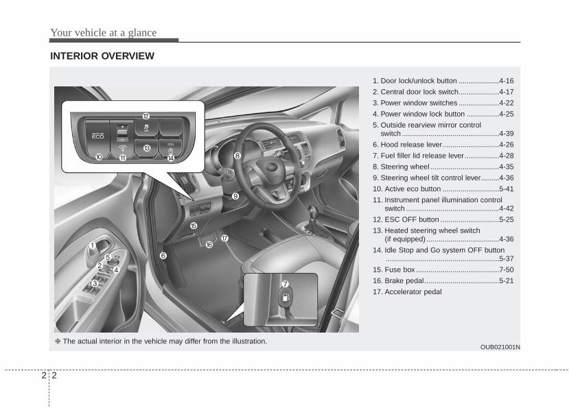
INTERIOR OVERVIEW
OUB021001N
1. Door lock/unlock button ....................4-16
2. Central door lock switch....................4-17
3. Power window switches ....................4-22
4. Power window lock button ................4-25
5. Outside rearview mirror control switch ................................................4-39
6. Hood release lever............................4-26
7. Fuel filler lid release lever .................4-28
8. Steering wheel ..................................4-35
9. Steering wheel tilt control lever.........4-36
10. Active eco button ............................5-41
11. Instrument panel illumination controlswitch ..............................................4-42
12. ESC OFF button .............................5-25
13. Heated steering wheel switch (if equipped)....................................4-36
14. Idle Stop and Go system OFF button........................................................5-37
15. Fuse box .........................................7-50
16. Brake pedal.....................................5-21
17. Accelerator pedal
❈ The actual interior in the vehicle may differ from the illustration.

2 3
Your vehicle at a glance
INSTRUMENT PANEL OVERVIEW
OUB021002N
1. Instrument cluster.............................4-41
2. Horn .................................................4-37
3. Driver’s front air bag.........................3-41
4. Light control/Turn signals .................4-70
5. Wiper/Washer...................................4-74
6. Ignition switch or ENGINE START/STOP button .................................5-4, 5-6
7. Hazard warning flasher switch ......4-70, 6-2
8. Audio ..............................................4-102
9. Climate control system.....................4-81
10. Shift lever...............................5-12, 5-15
11. Steering wheel audio control........4-103
12. Passenger’s front air bag ...............3-41
13. Glove box .......................................4-92
14. Parking brake lever ........................5-22
15. Power outlet ...................................4-99
16. Cigarette lighter ..............................4-96
17. Seat warmer .....................................3-7
❈ The actual instrument panel in the vehicle may differ from the illustration.
Your vehicle at a glance
42
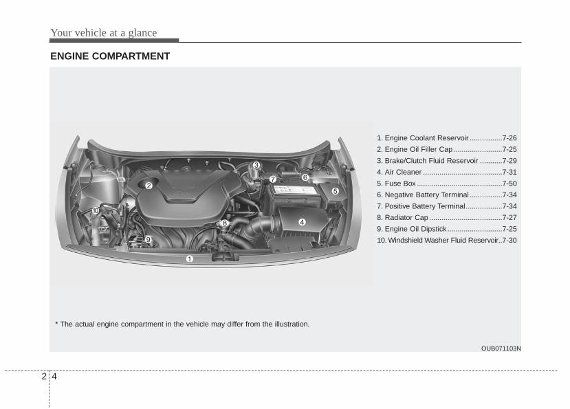
ENGINE COMPARTMENT
OUB071103N
* The actual engine compartment in the vehicle may differ from the illustration.
1. Engine Coolant Reservoir ................7-26
2. Engine Oil Filler Cap ........................7-25
3. Brake/Clutch Fluid Reservoir ...........7-29
4. Air Cleaner .......................................7-31
5. Fuse Box ..........................................7-50
6. Negative Battery Terminal ................7-34
7. Positive Battery Terminal..................7-34
8. Radiator Cap ....................................7-27
9. Engine Oil Dipstick ...........................7-25
10. Windshield Washer Fluid Reservoir..7-30

3
Seat / 3-2Seat belts / 3-12Child restraint system / 3-22Airbag-advanced supplemental restraint system / 3-30
Safety features of your vehicle

Safety features of your vehicle
23
Driver’s seat(1) Forward and rearward(2) Seatback angle(3) Seat cushion height(4) Seat warmer(5) Headrest
Front passenger’s seat(6) Forward and rearward(7) Seatback angle(8) Seat warmer(9) Headrest
Rear seat(10) Headrest(11) Seatback folding
SEAT
OUB031001N

3 3
Safety features of your vehicle
WARNING - Driver’s seat• Never attempt to adjust the seat
while the vehicle is moving. Thiscould result in loss of control ofyour vehicle.
• Do not allow anything to interferewith the normal position of theseatback. Storing items against aseatback or in any other wayinterfering with proper locking ofa seatback.
• Sit as far back as possible fromthe steering wheel while stillmaintaining comfortable controlof your vehicle. A distance of atleast 10" from your chest to thesteering wheel is recommended.Failure to do so can result inairbag inflation injuries to thedriver.
WARNING - Uprightingseat
Do not press the release lever on amanual seatback without holdingand controlling the seatback. Theseatback will spring upright possi-bly impacting you or other passen-gers.
WARNING - Loose objectsDo not place anything in the dri-ver's foot well or under the frontseats. Loose objects in the driver'sfoot area could interfere with theoperation of the foot pedals.
WARNING - Driver respon-sibility for passengers
The driver must advise the passen-ger to keep the seatback in anupright position whenever the vehi-cle is in motion. If a seat is reclinedduring an accident, the occupant'ships may slide under the lap por-tion of the seat belt, applying greatforce to the unprotected abdomen.
WARNING- Seat cushionOccupants should never sit on seatcushions. The passenger's hipsmay slide under the lap portion ofthe seat belt during an accident ora sudden stop.
Safety features of your vehicle
43
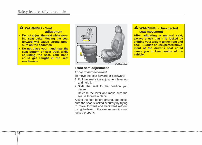
Front seat adjustmentForward and backwardTo move the seat forward or backward:1. Pull the seat slide adjustment lever up
and hold it.2. Slide the seat to the position you
desire.3. Release the lever and make sure the
seat is locked in place.Adjust the seat before driving, and makesure the seat is locked securely by tryingto move forward and backward withoutusing the lever. If the seat moves, it is notlocked properly.
OUB031002
WARNING - Seat adjustment
• Do not adjust the seat while wear-ing seat belts. Moving the seatforward will cause strong pres-sure on the abdomen.
• Do not place your hand near theseat bottom or seat track whileadjusting the seat. Your handcould get caught in the seatmechanism.
WARNING - Unexpectedseat movement
After adjusting a manual seat,always check that it is locked byshifting your weight to the front andback. Sudden or unexpected move-ment of the driver's seat couldcause you to lose control of thevehicle.

3 5
Safety features of your vehicle
Seatback angleTo recline the seatback:1. Lean forward slightly and lift up the
seatback recline lever.2. Carefully lean back on the seat and
adjust the seatback of the seat to theposition you desire.
3. Release the lever and make sure theseatback is locked in place. (The leverMUST return to its original position forthe seatback to lock.)
Seat height (for driver’s seat)To change the height of the seat, movethe lever upwards or downwards.• To lower the seat cushion, push down
the lever several times.• To raise the seat cushion, pull up the
lever several times.
HeadrestThe driver's and front passenger's seatsare equipped with a headrest for theoccupant's safety and comfort.The headrest not only provides comfortfor the driver and front passenger, butalso helps protect the head and neck inthe event of a collision.For maximum effectiveness in case of anaccident, the headrest should be adjust-ed so the middle of the headrest is at thesame height of the center of gravity of anoccupant's head. Generally, the center ofgravity of most people's head is similarwith the height of the top of their eyes.Also, adjust the headrest as close to yourhead as possible.
OUB031003 OUB031004 OUB031042N

Safety features of your vehicle
63
For this reason, the use of a cushion thatholds the body away from the seatback isnot recommended.
Forward and backward adjustment The headrest may be adjusted forward to4 different positions by pulling the head-rest forward to the desired detent. Toadjust the headrest to it’s furthest back-wards position, pull it fully forward to thefarthest position and release it. Adjust theheadrest so that it properly supports thehead and neck.
Adjusting the height up and downTo raise the headrest, pull it up to thedesired position (1). To lower the head-rest, push and hold the release button (2)on the headrest support and lower theheadrest to the desired position (3).
WARNING - Headrestremoval/adjustment
• Do not operate the vehicle withthe headrests removed.Headrests can provide criticalneck and head support in acrash.
• Do not adjust the headrest heightwhile the vehicle is in motion.Driver may lose control of thevehicle.
OUB031005OUB031007

3 7
Safety features of your vehicle
Removal and installationTo remove the headrest, raise it as far asit can go then press the release button(1) while pulling the headrest up (2).To reinstall the headrest, put the head-rest poles (3) into the holes while press-ing the release button (1). Then adjust itto the appropriate height.
Seat warmer (if equipped)The seat warmers are provided to warmthe front seats during cold weather. Withthe ignition switch in the ON position,push either of the switches to warm thedriver's seat or the front passenger'sseat.During mild weather or under conditionswhere the operation of the seat warmeris not needed, keep the switches in theOFF position.With the seat warmer switch in the ONposition, the heating system in the seatturns off or on automatically dependingon the seat temperature.
OUB031006 OUB031008
CAUTION - Seat damage• When cleaning the seats, do not
use an organic solvent such aspaint thinner, benzene, alcoholand gasoline. Doing so may dam-age the surface of the heater orseats.
• To prevent overheating the seatwarmer, do not place anything onthe seats that insulates againstheat, such as blankets, cushionsor seat covers while the seatwarmer is in operation.
• Do not place heavy or sharpobjects on seats equipped withseat warmers. Damage to the seatwarming components couldoccur.

Safety features of your vehicle
83
Seatback pocketThe seatback pocket is provided on theback of the front passenger’s seatback.
WARNING - Seat warmerburns
Passengers should use extremecaution when using seat warmersdue to the possibility of excessheating or burns. The seat warmermay cause burns even at low tem-peratures, especially if used forlong periods of time. The occu-pants must be able to feel if theseat is becoming too warm and toturn the seat warmer off. The seatwarmer may cause burns even atlow temperatures, especially ifused for long periods of time.In particular, the driver must exer-cise extreme care for the followingtypes of passengers:1. Infants, children, elderly or dis-
abled persons, or hospital outpa-tients
2. Persons with sensitive skin orthose that burn easily
3. Fatigued individuals4. Intoxicated individuals5. Individuals taking medication
that can cause drowsiness orsleepiness (sleeping pills, coldtablets, etc.)
WARNING - Seatbackpocket
Do not put heavy or sharp objectsin the seatback pocket. An occu-pant could contact such objects ina crash. Heavy objects in the frontpassenger seatback could alsointerfere with the airbag sensingsystem.
OUB031009
3 9
Safety features of your vehicle
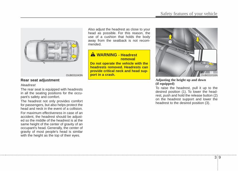
Rear seat adjustmentHeadrestThe rear seat is equipped with headrestsin all the seating positions for the occu-pant's safety and comfort.The headrest not only provides comfortfor passengers, but also helps protect thehead and neck in the event of a collision.For maximum effectiveness in case of anaccident, the headrest should be adjust-ed so the middle of the headrest is at thesame height of the center of gravity of anoccupant's head. Generally, the center ofgravity of most people's head is similarwith the height as the top of their eyes.
Also adjust the headrest as close to yourhead as possible. For this reason, theuse of a cushion that holds the bodyaway from the seatback is not recom-mended.
Adjusting the height up and down (if equipped)To raise the headrest, pull it up to thedesired position (1). To lower the head-rest, push and hold the release button (2)on the headrest support and lower theheadrest to the desired position (3).
OUB031043N
WARNING - Headrestremoval
Do not operate the vehicle with theheadrests removed. Headrests canprovide critical neck and head sup-port in a crash. OUB031016N

Safety features of your vehicle
103
Removal and installationTo remove the headrest, raise it as far asit can go then press the release button(1) while pulling the headrest upward (2).To reinstall the headrest, put the head-rest poles (3) into the holes while press-ing the release button (1). Then adjust itto the appropriate height and ensure thatit locks in position.Make sure the headrest locks in positionafter adjusting.
Folding the rear seatThe rear seatbacks may be folded tofacilitate carrying long items or toincrease the luggage capacity of thevehicle.
To fold down the rear seatback:1. Insert the rear seat belt metal tab into
the holder to prevent the seat belt formbeing damaged.
2. Set the front seatback to the uprightposition and if necessary, slide thefront seat forward.
3. Lower the rear headrests to lowestposition.
OUB031017N
WARNING Never allow passengers sit on topof the folded down seatback whilethe vehicle is moving. This is not aproper seating position and no seatbelts are available for use. Thiscould result in serious injury ordeath in case of an accident or sud-den stop.
WARNING - ObjectsObjects carried on the folded downseatback should not extend higherthan the top of the front seatbacks.This could allow cargo to slide for-ward and cause injury or damageduring sudden stops.
OTA030013

3 11
Safety features of your vehicle
4. Pull the lock release lever (1) and foldthe rear seatback forward and downfirmly.If the seat belt locks after unfolding therear seatback, pull out the locked seatbelt, release it then pull it out again.
To unfold the rear seat1. To use the rear seat, lift and pull the
seatback backward. Pull the seatbackfirmly until it clicks into place. Makesure the seatback is locked in place.When you return the seatback to itsupright position, always be sure it haslocked into position by pushing on thetop of the seatback.If you can not see the red line at thebottom of folding lever, it means theseatback is locked completely.
2. Return the rear seat belt to the properposition.
3. When the seatback is completelyinstalled, check the seatback foldinglever again.
When returning the rear seatbacks to theupright position, remember to return therear shoulder belts to their proper posi-tion.
OUB031018N
WARNING - Rear seatbackWhen returning the rear seatbackfrom a folded to an upright posi-tion, hold the seatback and return itslowly. Ensure that the seatback iscompletely locked into its uprightposition by pushing on the top ofthe seatback. In an accident or sud-den stop, the unlocked seatbackcould allow cargo to move forwardwith great force and enter the pas-senger compartment.
WARNING - CargoDo not place heavy objects in therear seats, since they cannot beproperly secured and may hit vehi-cle occupants in a frontal collision.

Safety features of your vehicle
123
Seat belt restraint systemSeat belts are designed to bear upon thebony structure of the body, and shouldbe worn low across the front of the pelvisor the pelvis, chest and shoulders, asapplicable; wearing the lap section of thebelt across the abdominal area must beavoided.Seat belts should be adjusted as firmlyas possible, consistent with comfort, toprovide the protection for which theyhave been designed.A slack belt will greatly reduce the pro-tection afforded to the wearer.Care should be taken to avoid contami-nation of the webbing with polishes, oilsand chemicals, and particularly batteryacid. Cleaning may safely be carried outusing mild soap and water. The beltshould be replaced if webbing becomesfrayed, contaminated or damaged.• For maximum restraint system protec-
tion, the seat belts must always beused whenever the vehicle is moving.A properly positioned shoulder beltshould be positioned midway over yourshoulder across your collarbone.
• Never allow children to ride in the frontpassenger seat. See child restraintsystem section for further discussion.
SEAT BELTS
WARNING - Shoulder beltNever wear the shoulder belt underyour arm or behind your back. Animproperly positioned shoulderbelt cannot protect the occupant ina crash.
WARNING - Damaged seatbelt
Replace the entire seat belt assem-bly if any part of the webbing orhardware is damage as you can nolonger be sure that a damage seatbelt will provide protection in acrash.
WARNING - Twisted seatbelt
Make sure your seat belt is nottwisted when worn. A twisted seatbelt may not properly protect you inan accident and could even cut intoyour body.
WARNING - Seat belt buckle
Do not allow foreign material (gum,crumbs, coins, etc.) to obstruct theseat belt buckle. This may preventthe seat belt from fastening secure-ly.

3 13
Safety features of your vehicle
Seat belt warning (for driver’s seat)The driver's seat belt warning light andchime will activate to the following tablewhen the ignition switch is in "ON" posi-tion.
*1 Warning pattern repeats 11 times withan interval of 24 seconds. If the driver'sseat belt is buckled, the light will stopwithin 6 seconds and chime will stopimmediately.
*2 The light will stop within 6 seconds andchime will stop immediately.
Seat belt warning (for front passen-ger’s seat)The front passenger's seat belt warninglight will activate to the following tablewhen the ignition switch is in "ON" posi-tion.
1GQA2083
Conditions Warning Pattern
Seat BeltVehicleSpeed
Light-BlinkChime-Sound
Unbuckled 6 seconds
Buckled 6 seconds None
Buckled →Unbuckled
Below 5 km/h(3 mph)
6 seconds None
5 km/h~10 km/h
6 seconds
Above 10 km/h(6 mph)
6 sec. on / 24 sec. off (11 times)
Unbuckled
Above 10 km/h(6 mph)
↓Below 5 km/h
(3 mph)
6 seconds *1
↓Stop *2
OUB031014N

Safety features of your vehicle
143
*1 The seat belt warning light will go off ifthe vehicle speed decreases below 5km/h (3 mph). If the vehicle speedincreases above 5 km/h (3 mph), thewarning light will blink again.
• You can find the front passenger's seatbelt warning light on the center fasciapanel.
• Although the front passenger seat isnot occupied, the seat belt warninglight will blink for 6 seconds.
• The seat belt warning light can blinkwhen a briefcase or purse is placed onthe front passenger seat.
Seat belt - Driver's 3-point systemwith emergency locking retractorTo fasten your seat belt:To fasten your seat belt, pull it out of theretractor and insert the metal tab (1) intothe buckle (2). There will be an audible"click" when the tab locks into the buckle.The seat belt automatically adjusts to theproper length only after the lap belt por-tion is adjusted manually so that it fitssnugly around your hips. If you lean for-ward in a slow, easy motion, the belt willextend and let you move around. If thereis a sudden stop or impact, however, thebelt will lock into position. It will also lockif you try to lean forward too quickly.
If you are not able to pull out the seat beltfrom the retractor, firmly pull the belt outand release it. Then you will be able topull the belt out smoothly.
Conditions Warning Pattern
Seat BeltVehicleSpeed
Light-Blink
Unbuckled 6 seconds
UnbuckledAbove 10 km/h
(6mph)Continuously
Buckled 6 seconds
Buckled →Unbuckled
Above 10 km/h(6mph)
Continuously *1
Below 10 km/h(6mph)
NoneB180A01NF-1

3 15
Safety features of your vehicle
Height adjustment You can adjust the height of the shoulderbelt anchor to one of the 4 positions formaximum comfort and safety.The height of the adjusting seat beltshould not be too close to your neck. Theshoulder portion should be adjusted sothat it lies across your chest and midwayover your shoulder near the door and notyour neck.To adjust the height of the seat beltanchor, lower or raise the height adjusterinto an appropriate position.
To raise the height adjuster, pull it up (1).To lower it, push it down (3) while press-ing the height adjuster button (2).Release the button to lock the anchorinto position. Try sliding the heightadjuster to make sure that it has lockedinto position.
You should place the lap belt portion aslow as possible and snugly across yourhips. If the lap belt is located too high onyour waist, it may increase the chance ofinjury in the event of a collision.The arm closest to the seat belt buckleshould be over the belt while the otherarm should be under the belt as shown inthe illustration.
OTA030017
Front seat
WARNING - Shoulder beltposition
Never position the shoulder beltacross your neck or face.
WARNING - Seat beltreplacement
Replace your seat belts after beingin an accident. Failure to replaceseat belts after an accident couldleave you with damaged seat beltsthat will not provide protection inthe event of another collision.
B200A01NF

Safety features of your vehicle
163
Seat belts - Front passenger and rearseat 3-point system with combinationlocking retractorTo fasten your seat belt: Combination retractor type seat belts areinstalled in the rear seat positions to helpaccommodate the installation of childrestraint systems. Although a combina-tion retractor is also installed in the frontpassenger seat position, it is stronglyrecommended that children always beseated in the rear seat. NEVER placeany infant restraint system in the frontseat of the vehicle.This type of seat belt combines the fea-tures of both an emergency lockingretractor seat belt and an automatic lock-ing retractor seat belt. To fasten your seatbelt, pull it out of the retractor and insertthe metal tab into the buckle. There willbe an audible "click" when the tab locksinto the buckle. When not securing achild restraint, the seat belt operates inthe same way as the driver's seat belt(Emergency Locking Retractor Type). Itautomatically adjusts to the proper lengthonly after the lap belt portion of the seatbelt is adjusted manually so that it fitssnugly around your hips.
When the seat belt is fully extended fromthe retractor to allow the installation of achild restraint system, the seat belt oper-ation changes to allow the belt to retract,but not to extend (Automatic LockingRetractor Type). Refer to “Using a childrestraint system” in this section.To convert from the automatic lockingfeature to the emergency locking opera-tion mode, allow the unbuckled seat beltto fully retract.
When using the rear center seat belt, thebuckle with the “CENTER” mark must beused.
OUB031020N

3 17
Safety features of your vehicle
To release the seat belt:The seat belt is released by pressing therelease button (1) of the locking buckle.When it is released, the belt should auto-matically draw back into the retractor.If this does not happen, check the belt tobe sure it is not twisted, then try again.
Pre-tensioner seat belt Your vehicle is equipped with driver's andfront passenger's pre-tensioner seatbelts. The purpose of the pre-tensioner isto make sure that the seat belts fit tightlyagainst the occupant's body in certainfrontal collisions (or side collisions). Thepre-tensioner seat belts may be activatedin crashes, where the frontal collision issevere enough.
When the vehicle stops suddenly, or ifthe occupant tries to lean forward tooquickly, the seat belt retractor will lockinto position. In certain frontal collisions,the pre-tensioner will activate and pullthe seat belt into tighter contact againstthe occupant's body.If the system senses excessive seat belttension on the driver or passenger's seatbelt when the pre-tensioner activates, theload limiter inside the pre-tensioner willrelease some of the pressure on theaffected seat belt.B210A01NF-1 OMG035300

Safety features of your vehicle
183
The seat belt pre-tensioner system con-sists mainly of the following components.Their locations are shown in the illustra-tion:1. SRS air bag warning light2. Retractor pre-tensioner assembly3. SRS control module4. Anchor pre-tensioner assembly
Both the driver's and front passenger'spre-tensioner seat belts may be activatedin certain frontal collisions.The pre-tensioners will not be activated ifthe seat belts are not being worn at thetime of the collision.
✽✽ NOTICEWhen the pre-tensioner seat belts areactivated, a loud noise may be heardand fine dust, which may appear to besmoke, may be visible in the passengercompartment. These are normal operat-ing conditions and are not hazardous.
Because the sensor that activates theSRS air bag is connected with the pre-tensioner seat belt, the SRS air bagwarning light ( ) on the instrumentpanel will illuminate for approximately 6seconds after the ignition switch hasbeen turned to the ON position, and thenit should turn off.If the pre-tensioner seat belt does notwork properly, this warning light will illu-minate even if the SRS air bag has notmalfunctioned. If the SRS air bag warn-ing light does not illuminate when theignition switch is turned ON, or if itremains illuminated after illuminating forapproximately 6 seconds, or if it illumi-nates while the vehicle is being driven,please have an authorized Kia dealerinspect the pre-tensioner seat belt orSRS air bag system as soon as possible.
1KMB3311A
WARNING - Skin irritationWash all exposed skin areas thor-oughly after an accident in whichthe pre-tensioner seat belts wereactivated. The fine dust from thepre-tensioner activation may causeskin irritation and should not bebreathed for prolonged periods.

3 19
Safety features of your vehicle
✽✽ NOTICEDo not attempt to service or repair thepre-tensioner seat belt system in anymanner. Do not attempt to inspect orreplace the pre-tensioner seat beltsyourself. This must be done by anauthorized Kia dealer.
Pre-tensioners are designed to operateonly one time. After activation, pre-ten-sioner seat belts must be replaced. If thepre-tensioner must be replaced, contactan authorized Kia dealer.
Seat belt precautionsInfant or small childYou should be aware of the specificrequirements in your country. Childand/or infant seats must be properlyplaced and installed in the rear seat. Formore information about the use of theserestraints, refer to “Child restraint sys-tem” in this section.
WARNING - Hot pretensioner
Do not touch the pre-tensioner seatbelt assemblies for several minutesafter they have been activated.When the pre-tensioner seat beltmechanism fires during a collisionthe pre-tensioner becomes hot andcan burn you.

Safety features of your vehicle
203
Larger childrenChildren who are too large for childrestraint systems should always occupythe rear seat and use the availablelap/shoulder belts. The lap portion shouldbe fastened and snugged on the hipsand as low as possible. Check if the beltfits periodically. A child's squirming couldput the belt out of position. Children aregiven the most safety in the event of anaccident when they are restrained by aproper restraint system in the rear seat. Ifa larger child (over age 12) must be seat-ed in the front seat, the child should besecurely restrained by the availablelap/shoulder belt and the seat should beplaced in the rearmost position. Childrenage 12 and under should be restrainedsecurely in the rear seat. NEVER place achild age 12 and under in the front seat.NEVER place a rear facing child seat inthe front seat of a vehicle.If the shoulder belt portion slightly touch-es the child’s neck or face, try placing thechild closer to the center of the vehicle. Ifthe shoulder belt still touches their faceor neck they need to be returned to achild restraint system.
Restraint of pregnant women Pregnant women should wear lap/shoul-der belt assemblies whenever possibleaccording to specific recommendationsby their doctors. The lap portion of thebelt should be worn AS SNUGLY ANDLOW AS POSSIBLE.
WARNING - Small childrenDo not allow small children to ridein the vehicle without an appropri-ate child restraint system. If theshoulder belt comes in contact withyour child's neck or face your childis too small to ride in the vehicle. Ina crash the seat belt will inflictinjury to your child's neck, throatand face.
WARNING - Pregnantwomen
Pregnant women must never placethe lap portion of the seat beltabove or on the abdomen wherethe fetus is located.The force of theseat belt during a collision willcrush the fetus.

3 21
Safety features of your vehicle
Injured personA seat belt should be used when aninjured person is being transported.When this is necessary, you should con-sult a physician for recommendations.
One person per beltTwo people (including children) shouldnever attempt to use a single seat belt.This could increase the severity ofinjuries in case of an accident.
Do not lie downTo reduce the chance of injuries in theevent of an accident and to achieve maxi-mum effectiveness of the restraint system,all passengers should be sitting up andthe front seats should be in an uprightposition when the vehicle is moving. Aseat belt cannot provide proper protectionif the person is lying down in the rear seator if the front seat is in a reclined position.
Care of seat beltsSeat belt systems should never be disas-sembled or modified. In addition, careshould be taken to assure that seat beltsand belt hardware are not damaged byseat hinges, doors or other abuse.
Periodic inspectionAll seat belts should be inspected peri-odically for wear or damage of any kind.Any damaged parts should be replacedas soon as possible.
Keep belts clean and drySeat belts should be kept clean and dry.If belts become dirty, they can becleaned by using a mild soap solutionand warm water. Bleach, dye, strongdetergents or abrasives should not beused because they may damage andweaken the fabric.
When to replace seat beltsThe entire in-use seat belt assembly orassemblies should be replaced if thevehicle has been involved in an accident.This should be done even if no damageis visible. Additional questions concern-ing seat belt operation should be directedto an authorized Kia dealer.
WARNING - Pinched seatbelt
Make sure that the webbing and/orbuckle does not get caught orpinched in the rear seat whenreturning the rear seatback to itsupright position. A caught orpinched webbing/buckle maybecome damaged and could failduring a collision or sudden stop.

Safety features of your vehicle
223
CHILD RESTRAINT SYSTEMChildren riding in the car should sit in therear seat and must always be properlyrestrained to minimize the risk of injury inan accident, sudden stop or suddenmaneuver. According to accident statis-tics, children are safer when properlyrestrained in the rear seats than in thefront seat. Larger children not in a childrestraint should use one of the seat beltsprovided.You should be aware of the specificrequirements in your country. Child and/orinfant safety seats must be properlyplaced and installed in the rear seat. Youmust use a commercially available childrestraint system that meets the require-ments of the safety standards of yourcountry.Child restraint systems are designed to besecured in vehicle seats by seat belt, or bya tether anchor and/or LATCH anchors (ifequipped).
Children could be injured or killed in acrash if their restraints are not properlysecured. For small children and babies, achild seat or infant seat must be used.Before buying a particular child restraintsystem, make sure it fits your vehicleseat and seat belts, and fits your child.Follow all the instructions provided by themanufacturer when installing the childrestraint system.
When the child restraint system is not inuse, store it in the luggage area or fastenit with a seat belt so that it will not bethrown forward in case of a sudden stopor an accident.
WARNING- Restraint location
Never install a child or infant seaton the front passenger's seat.A child riding in the front passen-ger seat can be forcefully struck byan inflating airbag.
WARNING- Hot childrestraint
A child restraint system canbecome very hot if it is left in aclosed vehicle on a sunny day. Besure to check the seat cover, buck-les and latches before placing achild in the restraint system.

3 23
Safety features of your vehicle
Using a child restraint systemFor small children and babies, the use ofa child seat or infant seat is required.Thischild seat or infant seat should be ofappropriate size for the child and shouldbe installed in accordance with the man-ufacturer's instructions.For safety reasons, we recommend thatthe child restraint system be used in therear seats.
WARNING - Holding children
Never hold a child in your arms orlap when riding in a vehicle. Theviolent forces created during acrash will tear the child from yourarms and throw the child againstthe car’s interior.Always use a child restraint systemwhich is appropriate for yourchild's height and weight.
WARNING - UnattendedChildren
Never leave children unattended ina vehicle. The car can heat up veryquickly, resulting in injuries to thechild in the vehicle.
WARNING - Seat belt useDo not use one seat belt for twooccupants at the same time. Thiswill eliminate any safety benefitprovided by the seat belt to theoccupants.
CRS09
OUB031012N
Rearward-facing child restraint system
Forward-facing child restraint system

Safety features of your vehicle
243
Since all passenger seat belts movefreely under normal conditions and onlylock under extreme or emergency condi-tions (emergency lock mode), you mustmanually change these seat belts to theauto lock mode to secure a childrestraint.If the seat belt does not operate asdescribed in this section, have the sys-tem checked immediately by your author-ized Kia dealer.
lacing a passenger seat belt into theauto lock mode The auto lock mode will help prevent thenormal movement of the child in the vehi-cle from causing the seat belt to loosenand compromise the child restraint sys-tem. To secure a child restraint system,use the following procedure.
WARNING - Child seatinstallation
• Always follow the instructionsprovided by the child restraintsystem manufacturer. Childrestraint system manufacturersknow their products best.
• Failure to observe this manual'sinstructions regarding childrestraint system and the instruc-tions provided with the childrestraint system could result inthe improper installation of thechild restraint system which mayreduce the protection to yourchild in a crash or a sudden stop.
E2MS103005

3 25
Safety features of your vehicle
To install a child restraint system on theoutboard or center rear seats, do the fol-lowing:1. Place the child restraint system in the
seat and route the lap/shoulder beltaround or through the restraint, follow-ing the restraint manufacturer’sinstructions. Be sure the seat belt web-bing is not twisted.
2. Fasten the lap/shoulder belt latch intothe buckle. Listen for the distinct “click”sound.
Position the release button so that it iseasy to access in case of an emergency.
3. Pull the shoulder portion of the seatbelt all the way out. When the shoulderportion of the seat belt is fully extend-ed, it will shift the retractor to the “AutoLock” (child restraint) mode.
4. Slowly allow the shoulder portion ofthe seat belt to retract and listen for anaudible “clicking” or “ratcheting” sound.This indicates that the retractor is inthe “Auto Lock” mode. If no distinctsound is heard, repeat steps 3 and 4.
OEN036101 OEN036102 OEN036103

Safety features of your vehicle
263
5. Remove as much slack from the beltas possible by pushing down on thechild restraint system while feeding theshoulder belt back into the retractor.
6. Push and pull on the child restraintsystem to confirm that the seat belt isholding it firmly in place. If it is not,release the seat belt and repeat steps2 through 6.
7. Double check that the retractor is inthe “Auto Lock” mode by attempting topull more of the seat belt out of theretractor. If you cannot, the retractor isin the “Auto Lock” mode.
The lap/shoulder belt automaticallyreturns to the “emergency lock mode”whenever the belt is allowed to retractfully.
Therefore, the preceding seven stepsmust be followed each time a childrestraint is installed.To remove the child restraint, press therelease button on the buckle and thenpull the lap/shoulder belt out of therestraint and allow the seat belt to retractfully.
Securing a child restraint seat withtether anchorage system Child restraint hook holders are locatedon the floor behind the rear seats.
OEN036104
WARNING - Auto lockmode
Set the retractor to Automatic Lockmode when installing any childrestraint system.If the retractor is not in theAutomatic Locking mode, the childrestraint can move when your vehi-cle turns or stops suddenly.
OUB031010
OUB031011
■ Type A
■ Type B

3 27
Safety features of your vehicle
1. Route the child restraint seat tetherstrap over the seatback.For vehicles with adjustable headrest,route the tether strap under the head-rest and between the headrest posts,otherwise route the tether strap overthe top of the seatback.
2. Connect the tether strap hook to theappropriate child restraint hook holderand tighten to secure the child restraintseat.
Check that the child restraint system issecure by pushing and pulling it in differ-ent directions. Incorrectly fitted childrestraints may swing, twist, tip or sepa-rate causing death or serious injury.
Securing a child restraint seat withchild seat lower anchor systemSome child seat manufacturers makechild restraint seats that are labeled asLATCH or LATCH-compatible childrestraint seats. LATCH stands for "LowerAnchors and Tethers for Children". Theseseats include two rigid or webbingmounted attachments that connect totwo LATCH anchors at specific seatingpositions in your vehicle. This type ofchild restraint seat eliminates the need touse seat belts to attach the child seat inthe rear seats.
WARNING - Tether strapNever mount more than one childrestraint to a single tether or to asingle lower anchorage point. Theincreased load caused by multipleseats may cause the tethers oranchorage points to break.OUB031013N 1SAE3090A

Safety features of your vehicle
283
Child restraint symbols are located onthe left and right rear seat backs to indi-cate the position of the lower anchors forchild restraints.
LATCH anchors have been provided inyour vehicle. The LATCH anchors arelocated in the left and right outboard rearseating positions. Their locations areshown in the illustration. There is noLATCH anchor provided for the centerrear seating position.The LATCH anchors are located betweenthe seatback and the seat cushion of therear seat left and right outboard seatingpositions.When you install your child's restraintsystem using the LATCH anchors bucklethe shoulder lap belt, then lock theretractor and pull the belt to remove theslack in the belt so it lies flat against thevehicle seat.
OUB031039N
Lower AnchorPosition Indicator
Lower Anchor
WARNING - Unused rearseatbelts
Always fasten the seatbelts behindthe child restraint seat when theyare not used to secure the childseat. Failure to do so may result inchild strangulation.
OUN036140L

3 29
Safety features of your vehicle
Follow the child seat manufacturer’sinstructions to properly install childrestraint seats with LATCH or LATCH-compatible attachments.Once you have installed the LATCH childrestraint, assure that the seat is properlyattached to the LATCH and tetheranchors.Also, test the child restraint seat beforeyou place the child in it. Tilt the seat fromside to side. Also try to tug the seat for-ward. Check to see if the anchors holdthe seat in place.
WARNING - LATCH loweranchors
Never attempt to attach a LATCHequipped seat in the center seatingposition. LATCH lower anchors areonly to be used with the left andright rear outboard seating posi-tions. You may damage theanchors or the anchors may failand break in a collision.

Safety features of your vehicle
303
(1) Driver’s front air bag(2) Passenger’s front air bag(3) Side impact air bag(4) Curtain air bag
Even in vehicles with air bags, you andyour passengers must always wear thesafety belts provided in order to minimizethe risk and severity of injury in the eventof a collision or rollover.
AIR BAG - ADVANCED SUPPLEMENTAL RESTRAINT SYSTEM
OYF039050
❈ The actual air bags in the vehicle may differ from the illustration.

3 31
Safety features of your vehicle
How does the air bag systemoperate • Air bag are activated (able to inflate if
necessary) only when the ignitionswitch is turned to the ON or STARTthe appropriate position.
• Air bags inflate instantly in the event ofserious frontal or side collision (ifequipped with side impact air bag orcurtain air bag) in order to help protectthe occupants from serious physicalinjury.
• There is no single speed at which theair bags will inflate.Generally, air bags are designed toinflate based upon the severity of a col-lision and its direction. These two fac-tors determine whether the sensorsproduce an electronic deployment/inflation signal.
• Air bag deployment depends on anumber of complex factors includingvehicle speed, angles of impact andthe density and stiffness of the vehi-cles or objects which your vehicle hitsin the collision. Though, factors are notlimited to those mentioned above.
• The front air bags will completelyinflate and deflate in an instant.
It is virtually impossible for you to seethe air bags inflate during an accident.It is much more likely that you will sim-ply see the deflated air bags hangingout of their storage compartments afterthe collision.
• In order to help provide protection in asevere collision, the air bags mustinflate rapidly. The speed of air baginflation is a consequence of extremelyshort time in which a collision occursand the need to get the air bagbetween the occupant and the vehiclestructures before the occupant impactsthose structures. This speed of inflationreduces the risk of serious or life-threatening injuries in a severe collisionand is thus a necessary part of air bagdesign.However, air bag inflation can alsocause injuries which can include facialabrasions, bruises and broken bonesbecause the inflation speed also caus-es the air bags to expand with a greatdeal of force.
• There are even circumstancesunder which contact with the steer-ing wheel air bag can cause fatalinjuries, especially if the occupantis positioned excessively close tothe steering wheel.
WARNING - Airbag inflation
Sit as far back as possible from thesteering wheel while still maintain-ing comfortable control of yourvehicle. A distance of at least 10"from your chest to the steeringwheel is recommended. Failure todo so can result in airbag inflationinjuries to the driver.

Safety features of your vehicle
323
Noise and smokeWhen the air bags inflate, they make aloud noise and they leave smoke andpowder in the air inside of the vehicle.This is normal and is a result of the igni-tion of the air bag inflator. After the airbag inflates, you may feel substantial dis-comfort in breathing due to the contact ofyour chest to both the seat belt and theair bag, as well as from breathing thesmoke and powder. Open your doorsand/or windows as soon as possibleafter the impact in order to reduce dis-comfort and prevent prolonged expo-sure to smoke and powder.Though smoke and powder are non-toxic, it may cause irritation to the skin(eyes, nose and throat etc). If this is thecase, wash and rinse with the cold waterimmediately and consult the doctor if thesymptom persists.
Installing a child restraint on a frontpassenger’s seat is forbiddenNever place a rear-facing child restraintin the front passenger’s seat. If the airbag deploys, it would impact the rear-fac-ing child restraint, causing serious orfatal injury.In addition, do not place front-facing childrestraint in the front passenger’s seateither. If the front passenger air baginflates, it would cause serious or fatalinjuries to the child.
1JBH3051
WARNING - Hot components
Do not touch the air bag storagearea's internal components imme-diately after airbag inflation. The airbag related parts in the steeringwheel, instrument panel and theroof rails above the front and reardoors are very hot. Hot compo-nents can result in burn injuries.

3 33
Safety features of your vehicle
Air bag warning lightThe purpose of the air bag warning lightin your instrument panel is to alert you ofa potential problem with your air bag -Supplemental Restraint System (SRS).When the ignition switch is turned ON,the indicator light should illuminate forapproximately 6 seconds, then go off.Have the system checked by an author-ized Kia dealer if:• The light does not turn on briefly when
you turn the ignition ON.• The light stays on after illuminating for
approximately 6 seconds.• The light comes on while the vehicle is
in motion.
SRS components and functionsThe SRS consists of the following com-ponents:1. Driver's front air bag module2. Passenger's front air bag module3. Side impact air bag modules4. Curtain air bag modules5. Retractor pre-tensioner assemblies*6. Air bag warning light7. SRS control module (SRSCM)8. Front impact sensors9. Side impact sensors10. PASSENGER AIR BAG “OFF” indi-
cator (Front passenger’s seat only)11. Occupant detection system
(Front passenger’s seat only)
W7-147
WARNING - Air bagdeployment
When children are seated in therear outboard seats of a vehicleequipped with side and/or curtainair bags, install the child restraintsystem as far away from the doorside as possible. Inflation of theside and/or curtain air bags couldimpact the child.
OUB031041N
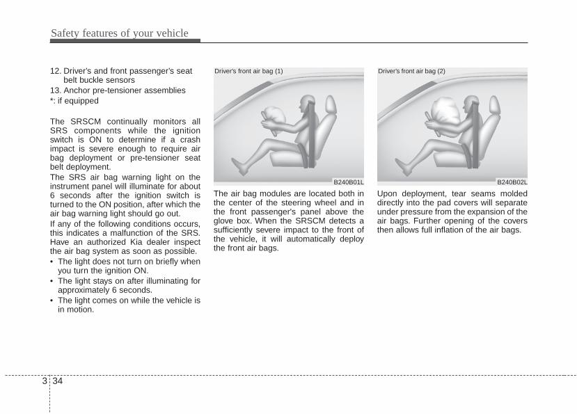
Safety features of your vehicle
343
12. Driver’s and front passenger’s seatbelt buckle sensors
13. Anchor pre-tensioner assemblies*: if equipped
The SRSCM continually monitors allSRS components while the ignitionswitch is ON to determine if a crashimpact is severe enough to require airbag deployment or pre-tensioner seatbelt deployment.The SRS air bag warning light on theinstrument panel will illuminate for about6 seconds after the ignition switch isturned to the ON position, after which theair bag warning light should go out.If any of the following conditions occurs,this indicates a malfunction of the SRS.Have an authorized Kia dealer inspectthe air bag system as soon as possible.• The light does not turn on briefly when
you turn the ignition ON.• The light stays on after illuminating for
approximately 6 seconds.• The light comes on while the vehicle is
in motion.
The air bag modules are located both inthe center of the steering wheel and inthe front passenger's panel above theglove box. When the SRSCM detects asufficiently severe impact to the front ofthe vehicle, it will automatically deploythe front air bags.
Upon deployment, tear seams moldeddirectly into the pad covers will separateunder pressure from the expansion of theair bags. Further opening of the coversthen allows full inflation of the air bags.
B240B01L
Driver’s front air bag (1)
B240B02L
Driver’s front air bag (2)

3 35
Safety features of your vehicle
B240B05L
Passenger’s front air bag
A fully inflated air bag, in combinationwith a properly worn seat belt, slows thedriver's or the passenger's forwardmotion, reducing the risk of head andchest injury.
After complete inflation, the air bagimmediately starts deflating, enabling thedriver to maintain forward visibility andthe ability to steer or operate other con-trols.
✽✽ NOTICEBefore you replace a fuse or disconnecta battery terminal, turn the ignitionswitch to the LOCK position andremove the ignition key. Never removeor replace the air bag related fuse(s)when the ignition switch is in the ONposition. Failure to heed this warningwill cause the SRS air bag warning lightto illuminate.
B240B03L
Driver’s front air bag (3)
WARNING - Air bagobstructions
Do not install or place any acces-sories on the steering wheel,instrument panel, or on the frontpassenger's panel above the glovebox in a vehicle Such objects maybecome dangerous projectiles ifthe air bag deploys.

Safety features of your vehicle
363
Occupant detection systemYour vehicle is equipped with an occu-pant detection system in the front pas-senger's seat.The occupant detection system isdesigned to detect the presence of aproperly-seated front passenger anddetermine if the passenger's front air bagshould be enabled (may inflate) or not.The driver's front air bag is not affectedor controlled by the occupant detectionsystem.
Main components of occupant detec-tion system• A detection device located within the
front passenger seat track.• Electronic system to determine
whether passenger air bag systemsshould be activated or deactivated.
• An indicator light located on the instru-ment panel which illuminates thewords PASSENGER AIR BAG “OFF”indicating the front passenger air bagsystem is deactivated.
• The instrument panel air bag warninglight is interconnected with the occu-pant detection system.
If the front passenger seat is occupied bya person that the system determines tobe of adult size, and he/she sits properly(sitting upright with the seatback in anupright position, centered on the seatcushion with their seat belt on, legs com-fortably extended and their feet on thefloor), the PASSENGER AIR BAG “OFF”indicator will turn off and the front pas-senger's air bag will be able to inflate, ifnecessary, in frontal crashes.You will find the PASSENGER AIR BAG“OFF” indicator on the center facia panel.This system detects the conditions 1~4in the following table and activates ordeactivates the front passenger air bagbased on these conditions.
OUB031037N

3 37
Safety features of your vehicle
Always be sure that you and all vehicleoccupants are seated and restrainedproperly (sitting upright with the seat inan upright position, centered on the seatcushion, with the person’s legs comfort-ably extended, feet on the floor, andwearing the safety belt properly) for themost effective protection by the air bagand the safety belt.
• The ODS (Occupant Detection System)may not function properly if the passen-ger takes actions which can defeat thedetection system. These include:
(1) Failing to sit in an upright position.(2) Leaning against the door or center
console.(3) Sitting towards the sides or the front
of the seat.(4) Putting legs on the dashboard or rest-
ing them on other locations whichreduce the passenger weight on thefront seat.
(5) Improperly wearing the safety belt.(6) Reclining the seat back.
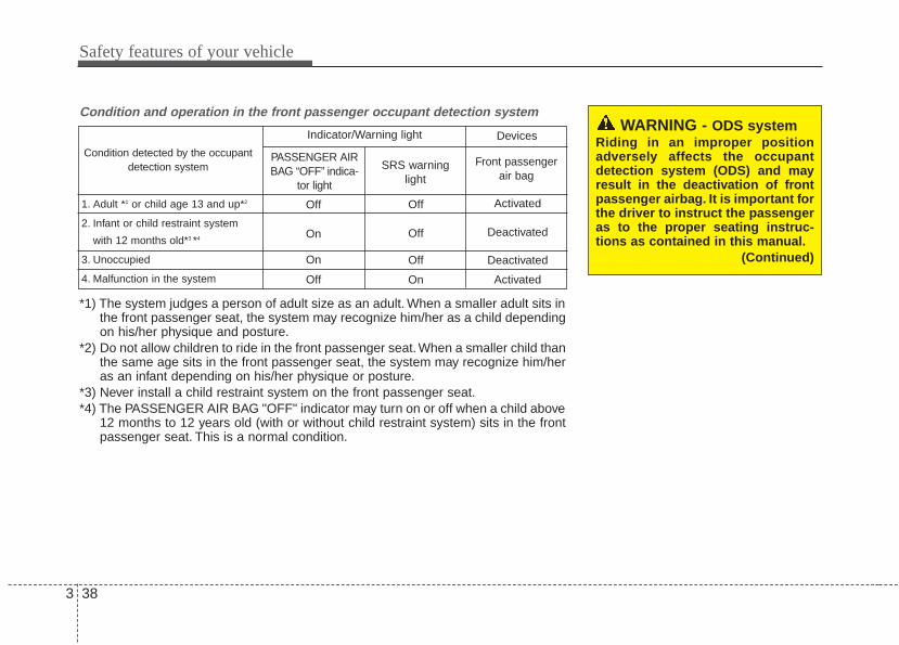
Safety features of your vehicle
383
WARNING - ODS systemRiding in an improper positionadversely affects the occupantdetection system (ODS) and mayresult in the deactivation of frontpassenger airbag. It is important forthe driver to instruct the passengeras to the proper seating instruc-tions as contained in this manual.
(Continued)
Condition and operation in the front passenger occupant detection system
*1) The system judges a person of adult size as an adult. When a smaller adult sits inthe front passenger seat, the system may recognize him/her as a child dependingon his/her physique and posture.
*2) Do not allow children to ride in the front passenger seat. When a smaller child thanthe same age sits in the front passenger seat, the system may recognize him/heras an infant depending on his/her physique or posture.
*3) Never install a child restraint system on the front passenger seat.*4) The PASSENGER AIR BAG "OFF" indicator may turn on or off when a child above
12 months to 12 years old (with or without child restraint system) sits in the frontpassenger seat. This is a normal condition.
Condition detected by the occupantdetection system
1. Adult *1 or child age 13 and up*2
2. Infant or child restraint system
with 12 months old*3 *4
3. Unoccupied
4. Malfunction in the system
Off
On
On
Off
Off
Off
Off
On
Activated
Deactivated
Deactivated
Activated
PASSENGER AIRBAG “OFF” indica-
tor light
SRS warninglight
Front passengerair bag
Indicator/Warning light Devices

3 39
Safety features of your vehicle
1KMN3663
1KMN3664
1KMN3665
- Never sit with the hips shiftedtowards the front of the seat.
- Never lean on the door or centerconsole.
- Never sit on one side of the frontpassenger seat.
- Never place the feet on the dash-board.
B990A08O
1KMN3662
- Never put a heavy load in thefront passenger seat.
- Never excessively recline thefront passenger seatback.
OVQ036014N
- Never place the feet on the frontpassenger seatback.
(Continued)

Safety features of your vehicle
403
When an adult is seated in the front pas-senger seat, if the PASSENGER AIRBAG “OFF” indicator is on, turn the igni-tion switch to the LOCK position and askthe passenger to sit properly (sittingupright with the seat back in an uprightposition, centered on the seat cushionwith their seat belt on, legs comfortablyextended and their feet on the floor).Restart the engine and have the personremain in that position. This will allow thesystem to detect the person and toenable the passenger air bag.
If the PASSENGER AIR BAG “OFF” indi-cator is still on, ask the passenger tomove to the rear seat.
✽✽ NOTICEThe PASSENGER AIR BAG “OFF”indicator illuminates for about 4 sec-onds after the ignition switch is turnedto the ON position or after the engine isstarted. If the front passenger seat isoccupied, the occupant detection sensorwill then classify the front passengerafter several more seconds.
B990A01O
WARNING - “AIR BAGOFF” light
Do not allow an adult passenger toride in the front seat when the PAS-SENGER AIR BAG “OFF” indicatoris illuminated, because the air bagwill not deploy in the event of acrash. The driver must instruct thepassenger to reposition himself inthe seat. Failure to properly posi-tion yourself may lead to airbagdeactivation resulting in airbagnon-deployment and in a collision.If the PASSENGER AIR BAG “OFF”indicator remains illuminated afterthe passenger repositions them-selves properly and the car isrestarted, it is recommended thatpassenger move to the rear seatbecause the passenger's front airbag will not deploy.

3 41
Safety features of your vehicle
Any child age 12 and under should ridein the rear seat. Children too large forchild restraints should use the availablelap/shoulder belts. No matter what typeof crash, children of all ages are saferwhen restrained in the rear seat.
✽✽ NOTICEDo not modify or replace the front pas-senger seat. Don't place anything on orattach anything such as a blanket, frontseat covers or after market seat heaterto the front passenger seat. This canadversely affect the occupant detectionsystem.
If the occupant detection system is notworking properly, the SRS air bag warn-ing light on the instrument panel willilluminate because the passenger's frontair bag is connected with the occupantdetection system. If there is a malfunc-tion of the occupant detection system,the PASSENGER AIR BAG “OFF” indica-tor will not illuminate and the passenger'sfront air bag will inflate in frontal impactcrashes even if there is no occupant inthe front passenger's seat.
Driver's and passenger's front airbagYour vehicle is equipped with anAdvanced Supplemental Restraint (AirBag) System and lap/shoulder belts atboth the driver and passenger seatingposition.
OUB031026
OUB031027
Driver’s front air bag
Passenger’s front air bag

Safety features of your vehicle
423
The indications of the system's presenceare the letters "AIR BAG" embossed onthe air bag pad cover in the steeringwheel and the passenger's side frontpanel pad above the glove box.
The SRS consists of air bags installedunder the pad covers in the center of thesteering wheel and the passenger's sidefront panel above the glove box.The purpose of the SRS is to provide thevehicle's driver and/or the front passen-ger with additional protection than thatoffered by the seat belt system alone incase of a frontal impact of sufficientseverity. The SRS uses sensors to gath-er information about the driver's seatposition, the driver's and front passen-ger's seat belt usage and impact severi-ty.
The advanced SRS offers the ability tocontrol the air bag inflation with two lev-els. A first stage level is provided for mod-erate-severity impacts. A second stagelevel is provided for more severe impacts.
The passenger’s front air bag is designedto help reduce the injury of children sit-ting close to the instrument panel in lowspeed collisions. However, children aresafer if they are restraint in the rear seat.
According to the impact severity, seatingposition and seat belt usage, the SRSCM(SRS Control Module) controls the airbag inflation. Failure to properly wearseat belts can increase the risk or sever-ity of injury in an accident.
Additionally, your vehicle is equippedwith an occupant detection system in thefront passenger's seat. The occupantdetection system detects the presence ofa passenger in the front passenger's seatand will turn off the front passenger's airbag under certain conditions. For moredetail, see "Occupant detection system"in this section.Do not place any objects that may causemagnetic fields near the front seat.Thesemay cause a malfunction of the seattrack position sensor.

3 43
Safety features of your vehicle
Manufacturers are required by govern-ment regulations to provide a contactpoint concerning modifications to thevehicle for persons with disabilities,which modifications may affect the vehi-cle’s advanced air bag system.However, Kia does not endorse nor will itsupport any changes to any part or struc-ture of the vehicle that could affect theadvanced air bag system, including theoccupant detection system.
Advanced air bags are combined withpre-tensioner seat belts to help provideenhanced occupant protection in frontalcrashes. Front air bags are not intendedto deploy in collisions in which sufficientprotection can be provided by the pre-tensioner seat belt alone.
Front air bags are not intended to deployin side-impact, rear-impact or rollovercrashes. In addition, front air bags will notdeploy in frontal crashes below thedeployment threshold.
WARNING - Replacement/modifications
The front passenger seat, dash-board or door should not bereplaced except by an authorizedKia dealer using original Kia partsdesigned for this vehicle andmodel. Any other such replacementor modification could adverselyaffect the operation of the occupantdetection system and youradvanced air bags.
WARNING - SRS WiringDo not tamper with or disconnectSRS wiring or other components ofthe SRS system. Doing so couldresult in injury, due to accidentaldeployment of the air bags or byrendering the SRS inoperative.
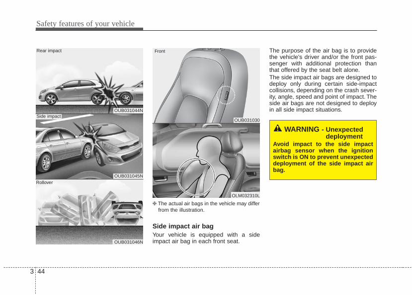
Safety features of your vehicle
443
❈ The actual air bags in the vehicle may differfrom the illustration.
Side impact air bagYour vehicle is equipped with a sideimpact air bag in each front seat.
The purpose of the air bag is to providethe vehicle's driver and/or the front pas-senger with additional protection thanthat offered by the seat belt alone.The side impact air bags are designed todeploy only during certain side-impactcollisions, depending on the crash sever-ity, angle, speed and point of impact. Theside air bags are not designed to deployin all side impact situations.
OUB031030
OLM032310L
Front
OUB031044N
OUB031045N
OUB031046N
Side impact
Rear impact
Rollover
WARNING - Unexpecteddeployment
Avoid impact to the side impactairbag sensor when the ignitionswitch is ON to prevent unexpecteddeployment of the side impact airbag.

3 45
Safety features of your vehicle
The side impact air bag is supplementalto the driver's and the passenger's seatbelt systems and is not a substitute forthem. Therefore your seat belts must beworn at all times while the vehicle is inoperation.For best protection from the side air bagsystem and to avoid being injured by thedeploying side air bag, both front seatoccupants should sit in an upright posi-tion with the seat belt properly fastened.The driver's hands should be placed onthe steering wheel at the 9:00 and 3:00positions. The passenger's arms andhands should be placed on their laps.
If seat or seat cover is damaged, havethe vehicle checked and repaired by anauthorized Kia dealer. Inform that yourvehicle is equipped with side impact airbags and an occupant detection system.
❈ The actual air bags in the vehicle may differfrom the illustration.
Curtain air bagCurtain air bags are located along bothsides of the roof rails above the front andrear doors.
WARNING - DeploymentDo not install any accessoriesincluding seat covers, on the sideor near the side impact air bag asthis may affect the deployment ofthe side air bags.
WARNING - Flying objectsDo not place any objects (anumbrella, bag, etc.) between thefront door and the front seat. Suchobjects may become dangerousprojectiles if the side airbaginflates.
OUB031019
OLM032311L

Safety features of your vehicle
463
They are designed to help protect theheads of the front seat occupants andthe rear outboard seat occupants in cer-tain side impact collisions.The curtain air bags are designed todeploy only during certain side impactcollisions, depending on the crash sever-ity, angle, speed and impact. The curtainair bags are not designed to deploy in allside impact situations, collisions from thefront or rear of the vehicle or in mostrollover situations.Do not allow the passengers to lean theirheads or bodies onto doors, put theirarms on the doors, stretch their arms outof the window, or place objects betweenthe doors and passengers when they areseated on seats equipped with sideand/or curtain air bags.
✽✽ NOTICENever try to open or repair any compo-nents of the side curtain air bag system.This should only be done by an author-ized Kia dealer.

3 47
Safety features of your vehicle
Why didn’t my air bag go off in acollision? (Inflation and non-infla-tion conditions of the air bag)There are many types of accidents inwhich the air bag would not be expect-ed to provide additional protection.These include rear impacts, second orthird collisions in multiple impactaccidents, as well as low speedimpacts. In other words, just becauseyour vehicle is damaged and even if itis totally unusable, don’t be surprisedthat the air bags did not inflate.
Air bag collision sensors(1) SRS control module(2) Front impact sensor
(3) Side impact sensor
1 2 3 3
OUB031031N/OUB031032/OUB031040N/OUB031033/OUB031047N
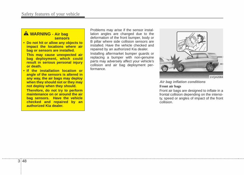
Safety features of your vehicle
483
Problems may arise if the sensor instal-lation angles are changed due to thedeformation of the front bumper, body orB pillar where side collision sensors areinstalled. Have the vehicle checked andrepaired by an authorized Kia dealer.Installing aftermarket bumper guards orreplacing a bumper with non-genuineparts may adversely affect your vehicle’scollision and air bag deployment per-formance.
Air bag inflation conditionsFront air bags Front air bags are designed to inflate in afrontal collision depending on the intensi-ty, speed or angles of impact of the frontcollision.
WARNING - Air bag sensors
• Do not hit or allow any objects toimpact the locations where airbag or sensors are installed.This may cause unexpected airbag deployment, which couldresult in serious personal injuryor death.
• If the installation location orangle of the sensors is altered inany way, the air bags may deploywhen they should not or they maynot deploy when they should.Therefore, do not try to performmaintenance on or around the airbag sensors. Have the vehiclechecked and repaired by anauthorized Kia dealer.
1VQA2084
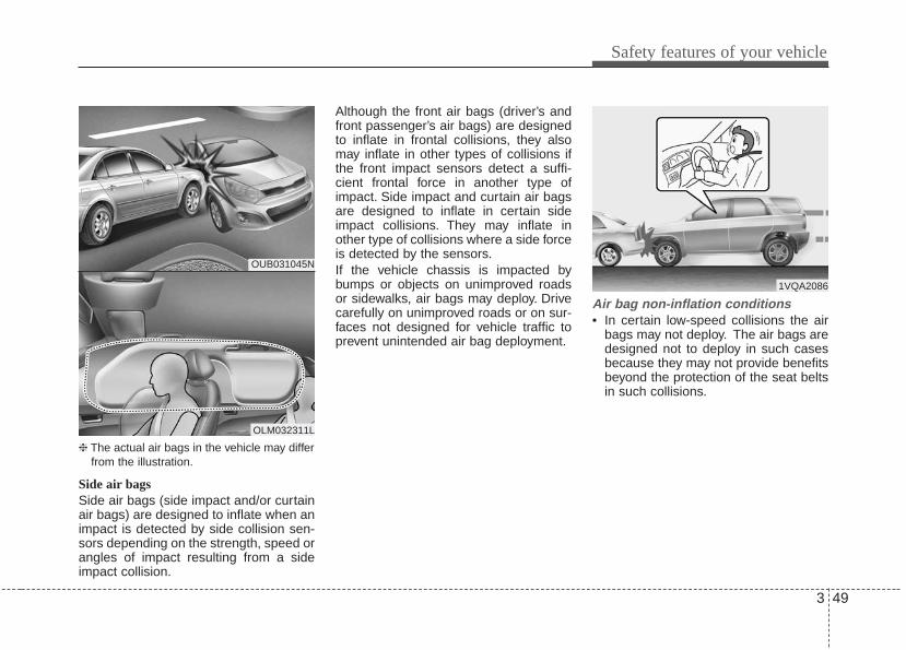
3 49
Safety features of your vehicle
❈ The actual air bags in the vehicle may differfrom the illustration.
Side air bagsSide air bags (side impact and/or curtainair bags) are designed to inflate when animpact is detected by side collision sen-sors depending on the strength, speed orangles of impact resulting from a sideimpact collision.
Although the front air bags (driver’s andfront passenger’s air bags) are designedto inflate in frontal collisions, they alsomay inflate in other types of collisions ifthe front impact sensors detect a suffi-cient frontal force in another type ofimpact. Side impact and curtain air bagsare designed to inflate in certain sideimpact collisions. They may inflate inother type of collisions where a side forceis detected by the sensors.If the vehicle chassis is impacted bybumps or objects on unimproved roadsor sidewalks, air bags may deploy. Drivecarefully on unimproved roads or on sur-faces not designed for vehicle traffic toprevent unintended air bag deployment.
Air bag non-inflation conditions• In certain low-speed collisions the air
bags may not deploy. The air bags aredesigned not to deploy in such casesbecause they may not provide benefitsbeyond the protection of the seat beltsin such collisions.
OUB031045N
OLM032311L
1VQA2086

Safety features of your vehicle
503
• Air bags are not designed to inflate inrear collisions, because occupants aremoved backward by the force of theimpact. In this case, inflated air bagswould not be able to provide any addi-tional benefit.
• Front air bags may not inflate in sideimpact collisions, because occupantsmove to the direction of the collision,and thus in side impacts, front air bagdeployment would not provide addi-tional occupant protection.
• In a slant or angled collision, the forceof impact may direct the occupants in adirection where the air bags would notbe able to provide any additional bene-fit, and thus the sensors may notdeploy any air bags.
OUN036087 1VQA2089OUB031045N

3 51
Safety features of your vehicle
• Just before impact, drivers often brakeheavily. Such heavy braking lowers thefront portion of the vehicle causing it to“ride” under a vehicle with a higherground clearance. Air bags may notinflate in this "under-ride" situationbecause deceleration forces that aredetected by sensors may be signifi-cantly replaced by such “under-ride”collisions.
• Air bags do not inflate in most rolloveraccidents, even though the vehicle isequipped with side impact air bags andcurtain air bags.
• Air bags may not inflate if the vehiclecollides with objects such as utilitypoles or trees, where the point ofimpact is concentrated to one area andthe full force of the impact is not deliv-ered to the sensors.
1VQA2090 OUB031046N 1VQA2092
Safety features of your vehicle
523
SRS CareThe SRS is virtually maintenance-freeand there are no parts you can safelyservice by yourself. If the SRS air bagwarning light does not illuminate, or con-tinuously remains on, have your vehicleimmediately inspected by an authorizedKia dealer.
Any work on the SRS system, such asremoving, installing, repairing, or anywork on the steering wheel must be per-formed by an authorized Kia dealer.Improper handling of the SRS systemmay result in serious personal injury.
For cleaning the air bag pad covers, useonly a soft, dry cloth or one which hasbeen moistened with plain water.Solvents or cleaners could adverselyaffect the air bag covers and properdeployment of the system.
If components of the air bag system mustbe discarded, or if the vehicle must bescrapped, certain safety precautionsmust be observed. An authorized Kiadealer knows these precautions and cangive you the necessary information.Failure to follow these precautions andprocedures could increase the risk ofpersonal injury.
Adding equipment to or modify-ing your air bag-equipped vehicleIf you modify your vehicle by changingyour vehicle's frame, bumper system,front end or side sheet metal or rideheight, this may affect the operation ofyour vehicle's air bag system.
WARNING - Tamperingwith SRS
Do not tamper with or disconnectSRS wiring, or other components ofthe SRS system. Doing so couldresult in the accidental inflation ofthe air bags or by rendering theSRS inoperative.

3 53
Safety features of your vehicle
Air bag warning labelAir bag warning labels, some required bythe Canada Motor Vehicle SafetyStandards (CMVSS), are attached to thesunvisor to alert the driver and passen-gers of potential risks of the air bag sys-tem.
OAM039041
OUB031035N

4
Keys / 4-2Smart key / 4-4Remote keyless entry / 4-7Theft-alarm system / 4-12Door locks / 4-15Tailgate / 4-20Windows / 4-22Hood / 4-26Fuel filler lid / 4-28
Sunroof / 4-31Steering wheel / 4-35Mirrors / 4-38Instrument cluster / 4-41Rearview camera / 4-69Hazard warning flasher / 4-70Lighting / 4-70Wipers and washers / 4-74Interior light / 4-78Defroster / 4-80Manual climate control system / 4-81Windshield defrosting and defogging / 4-90Storage compartment / 4-92Interior features / 4-96Audio system / 4-102
Features of your vehicle
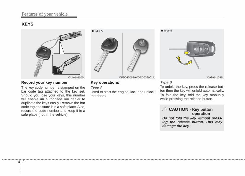
Features of your vehicle
24
Record your key numberThe key code number is stamped on thebar code tag attached to the key set.Should you lose your keys, this numberwill enable an authorized Kia dealer toduplicate the keys easily. Remove the barcode tag and store it in a safe place. Also,record the code number and keep it in asafe place (not in the vehicle).
Key operationsType AUsed to start the engine, lock and unlockthe doors.
Type BTo unfold the key, press the release but-ton then the key will unfold automatically.To fold the key, fold the key manuallywhile pressing the release button.
KEYS
OUN046100L
■ Type A
OAM041096L
■ Type B
OFD047002-A/OED036001A
CAUTION - Key buttonoperation
Do not fold the key without press-ing the release button. This maydamage the key.

4 3
Features of your vehicle
❈ The actual feature may differ from the illus-tration.
Type CTo remove the mechanical key, press andhold the release button and remove themechanical key.To reinstall the mechanical key, put thekey into the hole and push it until a clicksound is heard.
OUB041001N
■ Type C
WARNING - Aftermarketkeys
Use only Kia original parts for theignition key in your vehicle. If anaftermarket key is used, the ignitionswitch may not return to ON afterSTART. If this happens, the starterwill continue to operate causingpossible fire due to excessive cur-rent in the wiring.

Features of your vehicle
44
With a smart key, you can lock or unlocka door and even start the engine withoutinserting the key.The functions of the buttons on a smartkey are similar to the remote keylessentry. (Refer to the “Remote keylessentry” in this section.)
Smart key functionsCarrying the smart key, you may lock andunlock the vehicle doors. Also, you maystart the engine. Refer to the following,for more details.
Locking Pressing the button of the front outsidedoor handles with all doors closed andany door unlocked, locks all the doors.The hazard warning lights will blink andthe chime will sound once to indicate thatall doors are locked. The button will onlyoperate when the smart key is within0.7~1 m (28~40 in.) from the outsidedoor handle. If you want to make surethat a door has locked or not, you shouldcheck the door lock button inside thevehicle or pull the outside door handle.
SMART KEY (IF EQUIPPED)
OXM049001L
■ Type B
■ Type A
OUB041002N
OUB041004

4 5
Features of your vehicle
Even though you press the button, thedoors will not lock and the chime willsound for 3 seconds if any of the follow-ing occurs:• The smart key is in the vehicle.• The ignition switch is in the ACC or ON
position.• Any door except the trunk (or tailgate)
is opened.
Unlocking Pressing the button of the driver's out-side door handle with all doors closedand locked, unlocks the driver's door.Thehazard warning lights will blink and thechime will sound twice to indicate that thedriver's door is unlocked. All doors areunlocked if the button is pressed oncemore within 4 seconds. The hazard warn-ing lights will blink and the chime willsound twice to indicate that all the doorsare unlocked.Pressing the button in the front passen-ger's outside door handle with all doorsclosed and locked, unlocks all the doors.The hazard warning lights will blink andthe chime will sound twice to indicate thatall doors are unlocked. The button willonly operate when the smart key is with-in 0.7~1 m (28~40 in.) from the outsidedoor handle.
Tailgate unlocking (if equipped)If you are within 0.7 m (28 in.) from theoutside tailgate handle, with your smartkey in possession, the tailgate will unlockand open when you press the tailgatehandle switch.The hazard warning lights will blink twiceto indicate that the tailgate is unlocked.Also, once the tailgate is opened andthen closed, the tailgate will lock auto-matically.
Start-upYou can start the engine without insertingthe key. For detailed information refer to“Starting the engine with a smart key” insection 5.

Features of your vehicle
64
Smart key precautions• If you lose your smart key, you will not
be able to start the engine. Tow thevehicle, if necessary, and contact anauthorized Kia dealer.
• A maximum of 2 smart keys can beregistered to a single vehicle. If youlose a smart key, you should immedi-ately take the vehicle and key to yourauthorized Kia dealer to protect it frompotential theft.
• The smart key will not work if any of fol-lowing occurs:- The smart key is close to a radio
transmitter such as a radio station oran airport which can interfere withnormal operation of the smart key.
- The smart key near a mobile two-wayradio system or a cellular phone.
- Another vehicle’s smart key is beingoperated close to your vehicle.
When the smart key does not work cor-rectly, open and close the door with themechanical key. If you have a problemwith the smart key, contact an author-ized Kia dealer.
This device complies with IndustryCanada Standard RSS-210.Operation is subject to the following twoconditions:1. This device may not cause harmful
interference, and 2. This device must accept any interfer-
ence received, including interferencethat may cause undesired operation.
✽✽ NOTICEChanges or modifications not expresslyapproved by the party responsible forcompliance could void the user’sauthority to operate the equipment. Ifthe keyless entry system is inoperativedue to changes or modifications notexpressly approved by the party respon-sible for compliance, it will not be cov-ered by your manufacturer’s vehiclewarranty.
CAUTION - TransmitterKeep the smart key away fromwater or any liquid as it canbecome damaged and not functionproperly.

4 7
Features of your vehicle
Remote keyless entry systemoperations
Lock (1)All doors are locked if the lock button ispressed. If all doors (and trunk or tail-gate) are closed, the hazard warninglights will blink once to indicate that alldoors (and trunk or tailgate) are locked.Also, if the lock button is pressed oncemore within 4 seconds, the hazard warn-ing lights will blink and the chime willsound once to confirm that the door islocked.However, if any door remains open, thehazard warning lights (and/or the chime)will not operate. But if all doors areclosed after the lock button is pressed,the hazard warning lights will blink once.
Unlock (2) The driver's door is unlocked if the unlockbutton is pressed once. The hazardwarning lights will blink (for smart key, thechime also sounds) twice to indicate thatthe driver's door is unlocked.All doors are unlocked if the unlock but-ton is pressed once more within 4 sec-onds. The hazard warning lights will blink(for smart key, the chime also sounds)twice again to indicate that all doors areunlocked. After pressing this button, thedoors will lock automatically unless youopen any door within 30 seconds.
✽✽ NOTICEIf the keyless entry system is inoperativedue to exposure to water or liquids, itwill not be covered by your manufactur-er's vehicle warranty.
REMOTE KEYLESS ENTRY (IF EQUIPPED)
OAM041096L
OUB041003N
■ Type A
■ Type B
OXM049001L
■ Type C

Features of your vehicle
84
Tailgate open (3) (if equipped)The tailgate is opened if the button ispressed for more than 1 second.Once the tailgate is opened and thenclosed, the tailgate will lock automatical-ly.
Alarm (4)The horn sounds and the hazard warninglights blink for about 30 seconds if thisbutton is pressed for more than 0.5 sec-onds. To stop the horn and lights, pressany button on the transmitter.
Transmitter precautionsThe transmitter (or smart key) will notwork if any of following occurs:• The ignition key is in the ignition
switch.• You exceed the operating distance limit
(about 30 m [90 feet]).• The battery in the transmitter (or smart
key) is weak.• Other vehicles or objects may be
blocking the signal.• The weather is extremely cold.• The transmitter (or smart key) is close
to a radio transmitter such as a radiostation or an airport which can interferewith normal operation of the transmit-ter.
When the transmitter (or smart key) doesnot work properly, open and close thedoor with the ignition key. If you have aproblem with the transmitter (or smartkey), contact an authorized Kia dealer.
This device complies with IndustryCanada Standard RSS-210.Operation is subject to the following twoconditions:1. This device may not cause harmful
interference, and 2. This device must accept any interfer-
ence received, including interferencethat may cause undesired operation.
✽✽ NOTICEChanges or modifications not expresslyapproved by the party responsible forcompliance could void the user’sauthority to operate the equipment. Ifthe keyless entry system is inoperativedue to changes or modifications notexpressly approved by the party respon-sible for compliance, it will not be cov-ered by your manufacturer’s vehiclewarranty.

4 9
Features of your vehicle
Battery replacementA battery should last for several years,but if the transmitter or smart key is notworking properly, try replacing the bat-tery with a new one. If you are unsurehow to use or replace the battery, contactan authorized Kia dealer.
1. Pry open the transmitter or smart keycenter cover.
2. Replace the battery with a new battery(CR2032). When replacing the battery,make sure the battery positive “+” sym-bol faces up as indicated in the illus-tration.
3. Install the battery in the reverse orderof removal.
The transmitter or smart key is designedto give you years of trouble-free use,however it can malfunction if exposed tomoisture or static electricity. If you areunsure how to use or replace the battery,contact an authorized Kia dealer.Using the wrong battery can cause thetransmitter or smart key to malfunction.Be sure to use the correct battery.An inappropriately disposed battery canbe harmful to the environment andhuman health.Dispose the battery according to yourlocal law(s) or regulation.
CAUTION - Transmitterdamage
Do not drop, wet or expose the key-less entry system transmitter toheat or sunlight.
■ Type B, COED039003A
■ Type A
OSL040005

Features of your vehicle
104
Immobilizer systemYour vehicle may be equipped with anelectronic engine immobilizer system toreduce the risk of unauthorized vehicleuse.Your immobilizer system is comprised ofa small transponder in the ignition keyand electronic devices inside the vehicle.With the immobilizer system, wheneveryou insert your ignition key into the igni-tion switch and turn it to ON, it checksand determines and verifies that the igni-tion key is valid.If the key is determined to be valid, theengine will start.If the key is determined to be invalid, theengine will not start.
To deactivate the immobilizer sys-tem:Insert the ignition key into the key cylin-der and turn it to the ON position.
To activate the immobilizer system:Turn the ignition key to the OFF position.The immobilizer system activates auto-matically. Without a valid ignition key foryour vehicle, the engine will not start.Your Immobilizer password is a customerunique password and should be keptconfidential. Do not leave this numberanywhere in your vehicle.
✽✽ NOTICEKeep each key separately in order toavoid a starting malfunction.
Do not put metal accessories near theignition switch.Metal accessories may interrupt thetransponder signal and may prevent theengine from being started.If you need additional keys or lose yourkeys, consult an authorized Kia dealer.
OED036001A
CAUTION - Immobilizerdamage
Do not expose your immobilizersystem to moisture, static electrici-ty and rough handling. This maydamage your immobilizer.
CAUTION - Immobilizeralterations
Do not change, alter or adjust theimmobilizer system because itcould cause the immobilizer sys-tem to malfunction.

4 11
Features of your vehicle
This device complies with IndustryCanada Standard RSS-210.Operation is subject to the following twoconditions:1. This device may not cause harmful
interference, and 2. This device must accept any interfer-
ence received, including interferencethat may cause undesired operation.
Limp home (override) procedureWhen you turn the ignition switch to theON position, if the immobilizer indicator( ) goes off after blinking 5 times,your transponder equipped in the ignitionkey is out of order. You cannot start theengine without the limp home procedure.To start the engine, you have to inputyour password by using the ignitionswitch. Your password is only availablefrom an authorized Kia dealership.Contact an authorized dealer for moreinformation.The following procedure is how to inputyour password of “2345” as an example.1. Turn the ignition switch to the ON posi-
tion. The immobilizer indicator ( )will blink 5 times and go off indicatingthe beginning of the limp home proce-dure.
2. Turn the ignition switch to the ACCposition.
3. To enter the first digit (in this example“2”), turn the ignition switch to the ONand ACC position twice. Perform thesame procedure for the next digitsbetween 3 seconds and 10 seconds(for example, for “3”, turn the ignitionON and ACC 3 times).
4. If all of the digits have been input suc-cessfully, you have to start the enginewithin 30 seconds. If you attempt tostart the engine after 30 seconds, theengine will not start and you will haveto input your password again.
After performing the limp home proce-dure, you have to see an authorized Kiadealer immediately to inspect and repairyour ignition key or immobilizer system.
WARNINGChanges or modifications notexpressly approved by the partyresponsible for compliance couldvoid the user's authority to operatethe equipment.

Features of your vehicle
124
This system is designed to provide pro-tection from unauthorized entry into thevehicle. This system is operated in threestages: the first is the "Armed" stage, thesecond is the "Theft-alarm" stage, andthe third is the "Disarmed" stage. If trig-gered, the system provides an audiblealarm with blinking of the hazard warninglights.
Armed stagePark the vehicle and stop the engine.Arm the system as described below.1. Remove the ignition key from the igni-
tion switch and exit the vehicle.2. Make sure that all doors (and tailgate)
and engine hood are closed andlatched.
3. • Lock the doors by depressing thedoor lock button on the transmitter(or smart key).After completion of the steps above,the hazard warning lights will blinkonce to indicate that the system isarmed.If any door, tailgate or engine hoodremains open, the hazard warninglights won’t operate and theft-alarmwill not arm. After this, if all doors, tail-gate and engine hood are closed, thehazard warning lights blink once.
• Lock the doors by pressing the buttonof the front outside door handles withthe smart key in your possession.After completion of the steps above,the hazard warning lights will blinkonce to indicate that the system isarmed.If any door remains open, the hazardwarning lights won’t operate andtheft-alarm will not arm. Close thedoor and try again to lock the doors.If tailgate or engine hood remainsopen, the hazard warning lights won’toperate and theft-alarm will not arm.Close the tailgate or engine hood.The hazard warning lights blink onceand theft-alarm arms.
THEFT-ALARM SYSTEM (IF EQUIPPED)
Armedstage
Theft-alarmstage
Disarmedstage

4 13
Features of your vehicle
✽✽ NOTICEThe theft-alarm system by the key can beactivated by an authorized Kia dealer.If you want this feature, consult anauthorized Kia dealer.
Do not arm the system until all pas-sengers have left the vehicle. If thesystem is armed while a passenger(s)remains in the vehicle, the alarm maybe activated when the remaining pas-senger(s) leaves the vehicle. If anydoor (or tailgate) or engine hood isopened within 30 seconds after thesystem enters the armed stage, thesystem will be disarmed to preventunnecessary alarm.
Theft-alarm stageThe alarm will be activated if any of thefollowing occurs while the system isarmed.• A front or rear door is opened without
using the transmitter (or smart key).• The tailgate is opened without using
the transmitter (or smart key).• The engine hood is opened.The horn will sound and the hazardwarning lights will blink continuously forapproximately 27 seconds. To turn off thesystem, unlock the doors with the trans-mitter (or smart key).
Disarmed stageThe system will be disarmed when:
Transmitter- The door unlock button is pressed.- The engine is started. (within 3 sec-
onds)- The ignition switch is in the “ON” posi-
tion for 30 seconds or more.
Smart key- The door unlock button is pressed.- The button of the front outside door is
pressed while carrying the smart key.- The engine is started. (within 3 sec-
onds)
After the doors are unlocked, the hazardwarning lights will blink twice to indicatethat the system is disarmed.After pressing the unlock button, if anydoor (or tailgate) is not opened within 30seconds, the system will be rearmed.

Features of your vehicle
144
• Avoid trying to start the engine whilethe alarm is activated. The vehiclestarting motor is disabled during thetheft-alarm stage.If the system is not disarmed with thetransmitter, insert the key into the igni-tion switch, turn the ignition switch tothe ON position and wait for 30 sec-onds. Then the system will be dis-armed.
• If you lose your keys, consult yourauthorized Kia dealer.
• If the system is not disarmed with thetransmitter, insert the key into the igni-tion switch and start the engine. Thenthe system will be disarmed.
• If you lose your keys, consult yourauthorized Kia dealer.
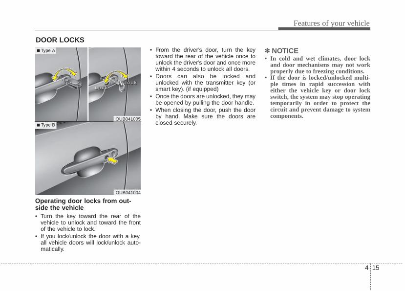
4 15
Features of your vehicle
DOOR LOCKS
Operating door locks from out-side the vehicle • Turn the key toward the rear of the
vehicle to unlock and toward the frontof the vehicle to lock.
• If you lock/unlock the door with a key,all vehicle doors will lock/unlock auto-matically.
• From the driver’s door, turn the keytoward the rear of the vehicle once tounlock the driver’s door and once morewithin 4 seconds to unlock all doors.
• Doors can also be locked andunlocked with the transmitter key (orsmart key). (if equipped)
• Once the doors are unlocked, they maybe opened by pulling the door handle.
• When closing the door, push the doorby hand. Make sure the doors areclosed securely.
✽✽ NOTICE• In cold and wet climates, door lock
and door mechanisms may not workproperly due to freezing conditions.
• If the door is locked/unlocked multi-ple times in rapid succession witheither the vehicle key or door lockswitch, the system may stop operatingtemporarily in order to protect thecircuit and prevent damage to systemcomponents.
OUB041004
■ Type B
■ Type A
OUB041005
LLLLoooocccckkkkUUUUnnnnlllloooocccckkkk

Features of your vehicle
164
• To lock a door without the key, push theinside door lock button (1) or centraldoor lock switch (2, if equipped) to the“Lock” position and close the door (3).
• If you lock the door with the centraldoor lock switch (2), all vehicle doorswill lock automatically. (if equipped withcentral door lock system)
Always remove the ignition key, engagethe parking brake, close all windows andlock all doors when leaving your vehicleunattended.
Operating door locks from insidethe vehicleWith the door lock button• To unlock a door, push the door lock
button (1) to the “Unlock” position. Thered mark (2) on the button will be visi-ble.
• To lock a door, push the door lock but-ton (1) to the “Lock” position. If the dooris locked properly, the red mark (2) onthe door lock button will not show.
• To open a door, pull the door handle(3) outward.
• If the inner door handle of the frontdoor is pulled when the door lock but-ton is in the lock position, the buttonwill unlock and the door will open. (ifequipped)
• Front doors cannot be locked if theignition key is in the ignition switch (orif the smart key is in the vehicle) andany front door is opened. (if equipped)
OUB041009
LLLLoooocccckkkk
UUUUnnnnlllloooocccckkkk
OUB041183N

4 17
Features of your vehicle
If a power door lock ever fails to functionwhile you are in the vehicle, try one ormore of the following techniques to exit:• Operate the door unlock feature
repeatedly (both electronic and manu-al) while simultaneously pulling on thedoor handle.
• Operate the other door locks and han-dles, front and rear.
• Lower a front window and use the keyto unlock the door from outside.
With central door lock switch (if equipped)Operate by pressing the central door lockswitch.• Press the switch to the "Lock" position
(1), all vehicle doors will lock.• Press the switch to the "Unlock" posi-
tion (2), all vehicle doors will unlock.• If the key is in the ignition switch (or if
the smart key is in the vehicle) and anyfront door is opened, the doors will notlock when the “Lock” position (1) of thecentral door lock switch is pressed. (ifequipped)
OUB041010/OUB041180N
Driver’s door Passenger’s door
WARNING- Unattended children/
animalsNever leave children or animalsunattended in your vehicle.An enclosed vehicle can becomeextremely hot, causing death orsevere injury to unattended chil-dren or animals who cannot escapethe vehicle.
WARNING - DoorsThe doors should always be fullyclosed and locked while the vehicleis in motion to prevent accidentalopening of the door.

Features of your vehicle
184
Impact sensing door unlock sys-tem (if equipped)All doors will automatically unlock whenan impact causes the air bags to deploy.
Auto door lock/unlock feature (if equipped)• All doors will automatically lock when
the transaxle shift lever is shifted out ofP (Park).
• All doors will automatically unlockwhen the transaxle shift lever is shiftedinto P (Park).
An authorized Kia dealer can activate ordeactivate some auto door lock/ unlockfeatures as follows;• Auto door unlock by using the driver's
door lock button• Auto door lock/unlock by shifting the
transaxle shift lever out of P (Park) orinto P (Park)
• Auto door unlock when the ignition keyis removed from the ignition switch (forsmart key, when the ENGINESTART/STOP button is turned to theOFF position)
If you want to activate or deactivate somedoor lock/unlock feature, consult anauthorized Kia dealer.
Child-protector rear door lockThe child safety lock is provided to helpprevent children from accidentally open-ing the rear doors from inside the vehicle.The rear door safety locks should beused whenever children are in the vehi-cle.1. Open the rear door.2. Insert a key (or screwdriver) into the
hole and turn it to the lock position.The child safety lock (1) located on therear edge of the door to the lock posi-tion. When the child safety lock is inthe lock position, rear door will notopen even when the inner door handleis pulled.
OUB041011

4 19
Features of your vehicle
3. Close the rear door.To open the rear door, pull the outsidedoor handle.Even though the doors may be unlocked,the rear door will not open by pulling theinner door handle until the rear door childsafety lock is unlocked.
WARNING - Rear doorlocks
Use the rear door safety lockswhenever children are in the vehi-cle. If a child accidently opens therear doors while the vehicle ismotion, he can fall out.

Features of your vehicle
204
Opening the tailgate■■ Type A• The tailgate is locked or unlocked by
turning the key to the "Lock" or"Unlock" position.
• If unlocked, the tailgate can be openedby pressing the handle and thanpulling up the hatch.
■■ Type B• The tailgate is locked or unlocked
when all doors are locked or unlockedwith the transmitter (or smart key) orcentral door lock switch.
• If unlocked, the tailgate can be openedby pressing the handle and pulling itup.
• All doors are locked if the tailgateunlock button on the smart key ispressed for more than 1 second andthe tailgate is unlocked. Once the tail-gate is opened and then closed, thetailgate is locks automatically.
❈ There is no key hole on this type.
The tailgate swings upward. Make sureno objects or people are near the rear ofthe vehicle when opening the tailgate.
TAILGATE
CAUTION - Tailgate liftcylinders
Make certain that you close the tail-gate before driving your vehicle.Possible damage may occur to thetailgate lift cylinders and attachinghardware if the tailgate is notclosed prior to driving.OUB041013OUB041012

4 21
Features of your vehicle
Closing the tailgateTo close the tailgate, lower and pushdown the tailgate firmly. Make sure thatthe tailgate is securely latched.Make sure your hands, feet and otherparts of your body are safely out of theway before closing the tailgate.
Emergency tailgate safety releaseYour vehicle is equipped with the emer-gency tailgate safety release lever locat-ed on the bottom of the tailgate. Whensomeone is inadvertently locked in theluggage compartment, the tailgate canbe opened by doing as follows:1. Remove the cover.2. Push the release lever to the right.3. Push up the tailgate.
CAUTION- Closing tailgateMake sure nothing is near the tail-gate latch and striker while closingthe tailgate. It may damage the tail-gate's latch.
OUB041014
WARNING - Exhaustfumes
Driving with the tailgate open is notadvisable. Dangerous exhaustfumes can enter the passengercompartment.If you must drive with the tailgateopened, keep the air vents and allwindows open so that additionaloutside air can enter.
WARNING - Riding incargo area
Occupants should never ride in therear cargo area where no restraintsare available. Occupants shouldalways be properly restrained.
OUB041015

Features of your vehicle
224
(1) Driver’s door power window switch*(2) Front passenger’s door power win-
dow switch*(3) Rear door (left) power window switch*(4) Rear door (right) power window
switch*(5) Window opening and closing(6) Automatic power window down*(7) Power window lock button*
*: if equipped
WINDOWS
OUB041016
4 23
Features of your vehicle
Power windowsThe ignition switch must be in the ONposition for power windows to operate.Each door has a power window switchthat controls the door’s window. The driv-er has a power window lock switch whichcan block the operation of passengerwindows.The power windows can be operated forapproximately 30 seconds after the igni-tion key is removed or turned to the ACCor LOCK position. However, if the frontdoors are opened, the power windowscannot be operated even within the 30second period.In cold and wet climates, power windowsmay not work properly due to freezingconditions.
✽✽ NOTICEWhile driving with the rear windowsdown or with the sunroof (if equipped)in an open (or partially open) position,your vehicle may demonstrate a windbuffeting or pulsation noise. This noiseis a normal occurrence and can bereduced or eliminated by taking the fol-lowing actions. If the noise occurs withone or both of the rear windows down,partially lower both front windowsapproximately one inch. If you experi-ence the noise with the sunroof open,slightly reduce the size of the sunroofopening.
Window opening and closing (if equipped)The driver’s door has a master powerwindow switch that controls all the win-dows in the vehicle.To open or close a window, press downor pull up the front portion of the corre-sponding switch to the first detent posi-tion (5).
Auto down window (if equipped) (Driver’s window)Pressing the power window switchmomentarily to the second detent posi-tion (6) completely lowers the driver’swindow even when the switch isreleased. To stop the window at thedesired position while the window is inoperation, momentarily pull up the switchto the opposite direction of the windowmovement.

Features of your vehicle
244
Auto up/down window (if equipped) Pressing or pulling up the power windowswitch momentarily to the second detentposition (6) completely lowers or lifts thewindow even when the switch is released.To stop the window at the desired positionwhile the window is in operation, pull upor press and release the switch to theopposite direction of the movement.If the power window is not operated cor-rectly, the automatic power window sys-tem must be reset as follows:1. Turn the ignition switch to the ON posi-
tion.2. Close the window and continue pulling
up on the driver’s power window switchfor at least 1 second after the window iscompletely closed.
Automatic reversal If the upward movement of the window isblocked by an object or part of the body,the window will detect the resistance andwill stop upward movement. The windowwill then lower approximately 30 cm (11.8in.) to allow the object to be cleared.If the window detects the resistancewhile the power window switch is pulledup continuously, the window will stopupward movement then lower approxi-mately 2.5 cm (1 in.). And if the powerwindow switch is pulled up continuouslyagain within 5 seconds after the windowis lowered by the automatic windowreversal feature, the automatic windowreversal will not operate.
✽✽ NOTICEThe automatic reverse feature for thedriver’s window is only active when the“auto up” feature is used by fullypulling up the switch. The automaticreverse feature will not operate if thewindow is raised using the halfway posi-tion on the power window switch.
OTA040015
WARNING Always check for obstructionsbefore raising any window to avoidinjuries or vehicle damage. If anobject less than 4 mm (0.16 in.) indiameter is caught between thewindow glass and the upper win-dow channel, the automatic reversewindow may not detect the resist-ance and will not stop and reversedirection.
OUN026013

4 25
Features of your vehicle
Power window lock button (if equipped)• The driver can disable the power win-
dow switches on the passenger doorsby pressing the power window lockswitch, located on the driver’s door tothe LOCK position (pressed).
• When the power window lock buttonis in the LOCK position (pressed),the driver’s master control cannotoperate the passenger door powerwindows.
Always double check to make sure allarms, hands, head and other obstruc-tions are safely out of the way beforeclosing a window.
Manual windows (if equipped)To raise or lower the window, turn thewindow regulator handle clockwise orcounterclockwise.When closing the windows, make sureyour passenger's arms, hands and bodyare safely out of the way.
CAUTION - Opening / closing Window
To prevent possible damage to thepower window system, do not openor close two windows or more at thesame time. This will also ensure thelongevity of the fuse.
WARNING - Power windows
Do not allow children to play withthe power windows. Keep the dri-ver’s door power window lockswitch in the LOCK position(pressed).
OUB041020 OSA028222
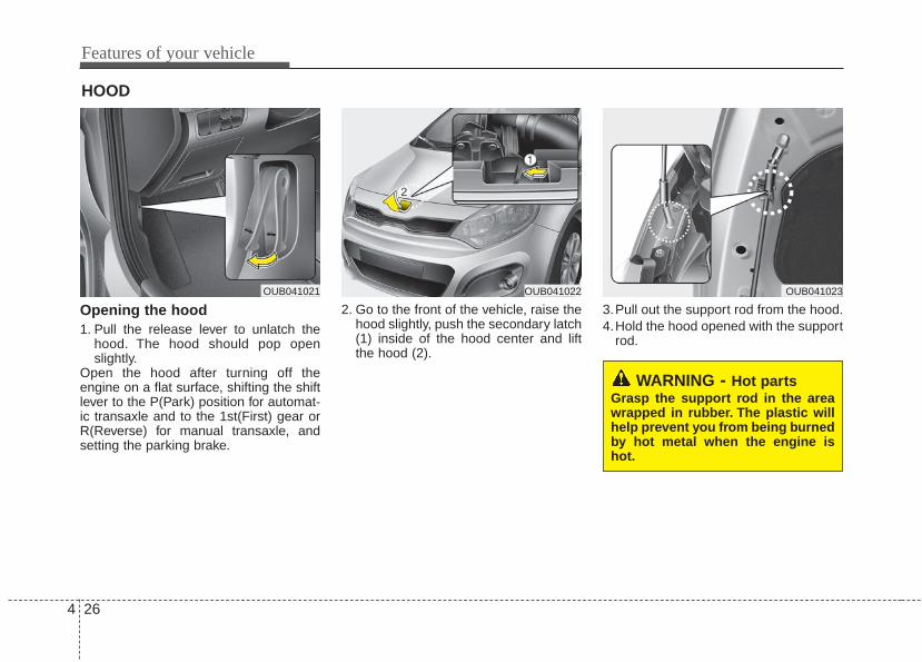
Features of your vehicle
264
Opening the hood 1. Pull the release lever to unlatch the
hood. The hood should pop openslightly.
Open the hood after turning off theengine on a flat surface, shifting the shiftlever to the P(Park) position for automat-ic transaxle and to the 1st(First) gear orR(Reverse) for manual transaxle, andsetting the parking brake.
2. Go to the front of the vehicle, raise thehood slightly, push the secondary latch(1) inside of the hood center and liftthe hood (2).
3.Pull out the support rod from the hood.4.Hold the hood opened with the support
rod.
HOOD
WARNING - Hot partsGrasp the support rod in the areawrapped in rubber. The plastic willhelp prevent you from being burnedby hot metal when the engine ishot.
OUB041021 OUB041022 OUB041023

4 27
Features of your vehicle
Closing the hood1. Before closing the hood, check the fol-
lowing:• All filler caps in the engine compart-
ment must be correctly installed.• Gloves, rags or any other com-
bustible material must be removedfrom the engine compartment.
2. Return the support rod to its clip toprevent it from rattling.
3. Lower the hood until it is about 30 cm(1 ft.) above the closed position and letit drop. Make sure that it locks intoplace.
The support rod must be inserted com-pletely into the hole whenever youinspect the engine compartment.This willprevent the hood from falling and possi-bly injuring you.
WARNING - Fire riskDo not leave gloves, rags or anyother combustible material in theengine compartment. Doing so maycause a heat-induced fire.
WARNING - Unsecuredengine Hood
Always double check to be surethat the hood is firmly latchedbefore driving away. If the enginehood is not secured properly, it islikely to fly up blocking your visionand causing a crash.

Features of your vehicle
284
Opening the fuel filler lidThe fuel filler lid must be opened frominside the vehicle by pulling up the fuelfiller lid opener.If the fuel filler lid does not open becauseice has formed around it, tap lightly orpush on the lid to break the ice andrelease the lid. Do not pry on the lid. Ifnecessary, spray around the lid with anapproved de-icer fluid (do not use radia-tor anti-freeze) or move the vehicle to awarm place and allow the ice to melt.
1. Stop the engine.2. To open the fuel filler lid, pull the fuel
filler lid opener up.3. Pull open the fuel filler lid (1).4. To remove the cap (2), turn the fuel
filler cap counterclockwise.5. Refuel as needed.
Closing the fuel filler lid1. To install the cap, turn it clockwise until
it “clicks” one time. This indicates thatthe cap is securely one time tightened.
2. Close the fuel filler lid and push it inlightly and make sure that it is secure-ly closed.
✽✽ NOTICETighten the cap until it clicks one time,otherwise the fuel cap open warningindicator light will illuminate.
FUEL FILLER LID
WARNING - RefuelingAlways remove the fuel cap careful-ly and slowly. If the cap is ventingfuel or if you hear a hissing sound,wait until the condition stopsbefore completely removing thecap.If pressurized fuel sprays out, it cancover your clothes or skin and sub-ject you to the risk of fire andburns.
OUB041024 OUB041025

4 29
Features of your vehicle
Always check that the fuel cap is installedsecurely to prevent fuel spillage in theevent of an accident.
✽✽ NOTICEWhen using an approved portable fuelcontainer, be sure to place the containeron the ground prior to refueling. Staticelectricity discharge from the containercan ignite fuel vapors causing a fire.Once refueling has begun, contact withthe vehicle should be maintained untilthe filling is complete. Use onlyapproved portable plastic fuel contain-ers designed to carry and store gasoline.
WARNING - Fire/explosionrisk
Read and follow all warnings post-ed at the gas station facility. Failureto follow all warnings will result insevere personal injury, severeburns or death due to fire or explo-sion.
WARNING - Cell phonefires
Do not use cellular phones whilerefueling. Electric current and/orelectronic interference from cellu-lar phones can potentially ignitefuel vapors causing a fire.
WARNING - Static electricity
• Before touching the fuel nozzle,you should eliminate potentiallydangerous static electricity dis-charge by touching another metalpart of the vehicle, a safe dis-tance away from the fuel fillerneck, nozzle, or other gas source.
• Do not get back into a vehicleonce you have begun refuelingsince you can generate staticelectricity by touching, rubbingor sliding against any item or fab-ric (polyester, satin, nylon, etc.)capable of producing static elec-tricity. Static electricity dischargecan ignite fuel vapors resulting inrapid burning. If you must re-enter the vehicle, you shouldonce again eliminate potentiallydangerous static electricity dis-charge by touching a metal partof the vehicle, away from the fuelfiller neck, nozzle or other gaso-line source.

Features of your vehicle
304
Make sure to refuel your vehicle accord-ing to the "Fuel requirements" suggestedin section 1.If the fuel filler cap requires replacement,use only a genuine Kia cap or the equiv-alent specified for your vehicle. An incor-rect fuel filler cap can result in a seriousmalfunction of the fuel system or emis-sion control system.
CAUTION - Exterior paintDo not spill fuel on the exterior sur-faces of the vehicle. Any type of fuelspilled on painted surfaces maydamage the paint.
WARNING - Refueling&Vehicle fires
When refueling, always shut theengine off. Sparks produced byelectrical components related tothe engine can ignite fuel vaporscausing a fire. Once refueling iscomplete, check to make sure thefiller cap and filler door are secure-ly closed, before starting theengine.
WARNING - SmokingDO NOT use matches or a lighterand DO NOT SMOKE or leave a litcigarette in your vehicle while at agas station especially during refu-eling. Automotive fuel is highlyflammable and can, when ignited,result in fire.

4 31
Features of your vehicle
If your vehicle is equipped with a sunroof,you can slide or tilt your sunroof with thesunroof control lever located on the over-head console.The sunroof can only be opened, closed,or tilted when the ignition switch is in theON position.
In cold and wet climates, the sunroof maynot work properly due to freezing condi-tions.After the vehicle is washed or in a rain-storm, be sure to wipe off any water thatis on the sunroof before operating it.
The sunroof cannot slide when it is in thetilt position nor can it be tilted while in anopen or slide position.
Sliding the sunroof To open the sunroof, pull the sunroofcontrol lever backward.To close the sunroof, push the sunroofcontrol lever forward.
SUNROOF (IF EQUIPPED)
CAUTION - Sunroof controllever
Do not continue to press the sun-roof control lever after the sunroofis fully opened, closed, or tilted.Damage to the motor or systemcomponents could occur.
OAM049018 OUB041027

Features of your vehicle
324
To open the sunroof automatically:Pull the sunroof control lever backward tothe second detent position and thenrelease it. The sunroof will slide all theway open.To stop the sunroof sliding at any point,pull or push the sunroof control levermomentarily.
To close the sunroof automatically:Push the sunroof control lever forward tothe second detent position and thenrelease it. The sunroof will automaticallyclose all the way.To stop the sunroof sliding at any point,pull or push the sunroof control levermomentarily.While driving with the sunroof in an open(or partially open position), your vehiclemay demonstrate a wind buffeting or pul-sation noise. This noise is a normaloccurrence and can be reduced or elimi-nated by taking the following actions. Ifyou experience the noise with the sun-roof open, slightly reduce the size of thesunroof opening
Automatic reversalIf an object or part of the body is detect-ed while the sunroof is closing automati-cally, it will reverse direction, and thenstop.The auto reverse function does not workif a tiny obstacle is between the slidingglass and the sunroof sash. You shouldalways check that all passengers andobjects are away from the sunroof beforeclosing it.
Tilting the sunroof To open the sunroof, push the sunroofcontrol lever upward until the sunroofmoves to the desired position.To close the sunroof, push the sunrooflever forward or pull downward until thesunroof moves to the desired position.
OBK049018 OUB041028

4 33
Features of your vehicle
Do not extend the face, neck, arms orbody outside the sunroof while driving.Periodically remove any dirt that mayaccumulate on the guide rail.While using sunroof for a long time, adust between sunroof and roof panel canmake a noise. Open the sunroof andremove regularly the dust using cleancloth.
Sunshade When opening the sunroof, the sunshadewill also open. Once the sunroof isclosed, the sunshade can be manuallyclosed.
OBK049019
WARNING - Sunroof operation
When closing the sunroof, makesure there are no body parts in themovement range of the sliding roof.Parts of the body could becometrapped or crushed.
CAUTION - Sunroof motordamage
If you try to open the sunroof whenthe temperature is below freezing orwhen the sunroof is covered withsnow or ice, the glass or the motorcould be damaged.

Features of your vehicle
344
Resetting the sunroofWhenever the vehicle battery is discon-nected or discharged, or related fuse isblown, you must reset your sunroof sys-tem as follows:
1. Turn the ignition switch to the ON posi-tion and close the sunroof completely.
2. Release the control lever.3. Push and hold the control lever for-
ward (for more than 10 seconds) untilthe sunroof tilts and slightly moves.Then, release the lever.
4. Within 3 seconds, push and hold thecontrol lever forward (for more than 5seconds) until the sunroof is operatedas follows;
TILT DOWN → SLIDE OPEN →SLIDE CLOSE
Then, release the control lever.
When this is complete, the sunroof sys-tem is reset.
❈ For more detailed information, contactan authorized Kia dealer.
✽✽ NOTICEIf the sunroof is not reset when the vehi-cle battery is disconnected or dis-charged, or related fuse is blown, thesunroof may operate improperly.

4 35
Features of your vehicle
Electric power steeringPower steering uses the motor to assistyou in steering the vehicle. If the engineis off or if the power steering systembecomes inoperative, the vehicle maystill be steered, but it will requireincreased steering effort.The motor driven power steering is con-trolled by the power steering control unitwhich senses the steering wheel torqueand vehicle speed to command themotor.The steering wheel becomes heavier asthe vehicle’s speed increases andbecomes lighter as the vehicle’s speeddecreases for better control of the steer-ing wheel.Should you notice any change in theeffort required to steer during normalvehicle operation, have the power steer-ing checked by an authorized Kia dealer.
✽✽ NOTICEThe following symptoms may occur dur-ing normal vehicle operation:• The steering effort is high immediate-
ly after turning the ignition switch on.This happens as the system performsthe EPS system diagnostics. When thediagnostics is completed, the steeringwheel will return to its normal condi-tion.
• A click noise may be heard from theEPS relay after the ignition switch isturned to the ON or LOCK position.
• Motor noise may be heard when thevehicle is at a stop or at a low drivingspeed.
• The steering effort increases if thesteering wheel is rotated continuouslywhen the vehicle is not in motion.However, after a few minutes, it willreturn to its normal conditions.
• When you operate the steering wheelin low temperature, abnormal noisecould occur. If temperature rises, thenoise will disappear. This is a normalcondition.
If the Electric Power Steering Systemdoes not operate normally, the warninglight will illuminate on the instrumentcluster. The steering wheel may becomedifficult to control or operate abnormally.Take your vehicle to an authorized Kiadealer and have the vehicle checked assoon as possible.
STEERING WHEEL

Features of your vehicle
364
Tilt and telescoping (if equipped)steering Tilt steering allows you to adjust thesteering wheel before you drive. You canalso raise it to give your legs more roomwhen you exit and enter the vehicle.
The steering wheel should be positionedso that it is comfortable for you to drive,while permitting you to see the instru-ment panel warning lights and gauges.
To change the steering wheel angle, pulldown the lock release lever (1), adjustthe steering wheel to the desired angle(2) and height (if equipped) (3), then pullup the lock-release lever to lock thesteering wheel in place. Be sure to adjustthe steering wheel to the desired positionbefore driving.
Heated steering wheel (if equipped)When the ignition switch is in the ONposition, pressing the heated steeringwheel button warms the steering wheel.The indicator on the button will illuminate.To turn the steering wheel off, press thebutton once again. The indicator on thebutton will turn off.It will turn off automatically approximate-ly 30 minutes after the heated steeringwheel is turned on.If the ignition is turned off and then onagain within a half hour (while the heatedsteering wheel button is pressed), thesteering wheel heating system willremain on.
WARNING - Steering wheeladjustment
Never adjust the angle and heightof the steering wheel while driving.You may lose steering control
OUB041029 OUB041030

4 37
Features of your vehicle
HornTo sound the horn, press the horn sym-bol on your steering wheel. Check thehorn regularly to be sure it operatesproperly.To sound the horn, press the area indi-cated by the horn symbol on your steer-ing wheel (see illustration). The horn willoperate only when this area is pressed.
OUB041031
CAUTION• Do not install any grip to operate
the steering wheel. This causesdamage to the heated steeringwheel system.
• When cleaning the heated steer-ing wheel, do not use an organicsolvent such as paint thinner,benzene, alcohol and gasoline.Doing so may damage the sur-face of the steering wheel.
• If the surface of steering wheel isdamaged by sharp object, dam-age to the heated steering wheelcomponents could occur.

Features of your vehicle
384
Inside rearview mirrorAdjust the rearview mirror so that thecenter view through the rear window isseen. Make this adjustment before youstart driving.Do not place objects in the rear seatwhich would interfere with your visionthrough the rear window.
Day/night rearview mirror (if equipped)Make this adjustment before you startdriving and while the day/night lever is inthe day position.Pull the day/night lever toward you toreduce the glare from the headlights ofthe vehicles behind you during night driv-ing.Remember that you lose some rearviewclarity in the night position.
Outside rearview mirror Be sure to adjust the mirror anglesbefore driving.Your vehicle is equipped with both left-hand and right-hand outside rearviewmirrors. The mirrors can be adjustedremotely with the remote switch (ifequipped). The mirror heads can be fold-ed to prevent damage during an auto-matic car wash or when passing througha narrow street.
MIRRORS
WARNING - Mirror adjustment
Do not adjust the rearview mirrorwhile the vehicle is moving. Thiscould result in loss of control.
OAM049023Day
Night

4 39
Features of your vehicle
The right outside rearview mirror is con-vex. Objects seen in the mirror are closerthan they appear.Use your interior rearview mirror or directobservation to determine the actual dis-tance of following vehicles when chang-ing lanes.
Remote controlElectric typeThe electric remote control mirror switchallows you to adjust the position of theleft and right outside rearview mirrors. Toadjust the position of either mirror theignition switch should be in the ACC orON position.
Move the lever (1) to R or L to select theright side mirror or the left side mirror,then press a corresponding point on themirror adjustment control to position theselected mirror up, down, left or right.After the adjustment, put the lever intoneutral (center) position to prevent inad-vertent adjustment.
CAUTION - Rearview mirror
Do not scrape ice off the mirrorface; this may damage the surfaceof the glass. If ice should restrictmovement of the mirror, do notforce the mirror for adjustment. Toremove ice, use a deicer spray, or asponge or soft cloth with very warmwater.
WARNING - Mirror adjustment
Do not adjust or fold the outsiderearview mirrors while the vehicleis moving. This could result in lossof control.
■ Type BOUB041032
OUB041033
■ Type A
CAUTION - Outside mirror• The mirrors stop moving when
they reach the maximum adjust-ing angles, but the motor contin-ues to operate while the switch ispressed. Do not press the switchlonger than necessary, the motormay be damaged.
• Do not attempt to adjust the out-side rearview mirror by hand.Doing so may damage the relatedparts.
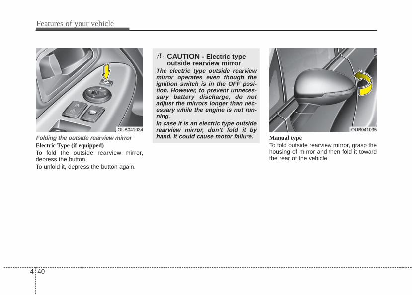
Features of your vehicle
404
Folding the outside rearview mirrorElectric Type (if equipped)To fold the outside rearview mirror,depress the button.To unfold it, depress the button again.
Manual typeTo fold outside rearview mirror, grasp thehousing of mirror and then fold it towardthe rear of the vehicle.
CAUTION - Electric typeoutside rearview mirror
The electric type outside rearviewmirror operates even though theignition switch is in the OFF posi-tion. However, to prevent unneces-sary battery discharge, do notadjust the mirrors longer than nec-essary while the engine is not run-ning.In case it is an electric type outsiderearview mirror, don’t fold it byhand. It could cause motor failure.
OUB041035OUB041034

4 41
Features of your vehicle
INSTRUMENT CLUSTER
1. Tachometer
2. Turn signal indicators
3. Speedometer
4. Fuel gauge
5. Engine coolant temperature gauge6. Warning and indicator lights
7. Shift position indicator (A/T) or Manual transaxle shift indicator (M/T)
8. Odometer/Trip computer
❈ The actual cluster in the vehicle may differfrom the illustration.For more details refer to the "Gauges" inthe next pages.
OUB041036C/OUB041037C
■■ Type A
■■ Type B
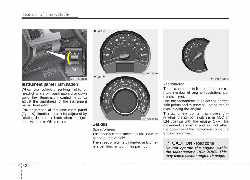
Features of your vehicle
424
Instrument panel illumination When the vehicle’s parking lights orheadlights are on, push upward or downward the illumination control knob toadjust the brightness of the instrumentpanel illumination.The brightness of the instrument panel(Type B) illumination can be adjusted byrotating the control knob when the igni-tion switch is in ON position.
GaugesSpeedometer The speedometer indicates the forwardspeed of the vehicle.The speedometer is calibrated in kilome-ters per hour and/or miles per hour.
Tachometer The tachometer indicates the approxi-mate number of engine revolutions perminute (rpm).Use the tachometer to select the correctshift points and to prevent lugging and/orover-revving the engine.The tachometer pointer may move slight-ly when the ignition switch is in ACC orON position with the engine OFF. Thismovement is normal and will not affectthe accuracy of the tachometer once theengine is running.
CAUTION - Red zoneDo not operate the engine withinthe tachometer's RED ZONE. Thismay cause severe engine damage.
OUB041045NOUB041038■ Type B
OUB041040
OUB041043
■ Type A

4 43
Features of your vehicle
Engine coolant temperature gauge(for Type B cluster) This gauge shows the temperature of theengine coolant when the ignition switchis ON.Do not continue driving with an overheat-ed engine. If your vehicle overheats, referto “If the engine overheats” in section 6.If the gauge pointer moves beyond thenormal range area toward the “H” posi-tion, it indicates overheating that maydamage the engine.
Fuel gaugeThe fuel gauge indicates the approxi-mate amount of fuel remaining in the fueltank. The fuel tank capacity is given insection 8. The fuel gauge is supplement-ed by a low fuel warning light, which willilluminate when the fuel tank is nearlyempty.
On inclines or curves, the fuel gaugepointer may fluctuate or the low fuelwarning light may come on earlier thanusual due to the movement of fuel in thetank.
OUB041048N■ Type B
OUB041046N
OUB041047N
■ Type A

Features of your vehicle
444
Odometer OdometerThe odometer indicates the total dis-tance the vehicle has been driven.You will also find the odometer useful todetermine when periodic maintenanceshould be performed.
✽✽ NOTICEIt is forbidden to alter the odometer ofall vehicles with the intent to change themileage registered on the odometer. Thealteration may void your warranty cov-erage.
WARNING - Fuel gaugeStop and obtain additional fuel assoon as possible after the warninglight comes on or when the gaugeindicator comes close to the Elevel. Running out of fuel canexpose vehicle occupants to dan-ger.
CAUTION - Low fuelAvoid driving with extremely lowfuel level. Running out of fuel couldcause the engine to misfire, damag-ing the catalytic converter.
OUB041050C
■ Type A ■ Type B

4 45
Features of your vehicle
Trip computer (Tripmeter) (if equipped)The trip computer is a microcomputer-controlled driver information system thatdisplays information related to driving,when the ignition switch is in the ONposition. All stored driving information(except distance to empty and instantfuel consumption) will reset if the batteryis disconnected.
OUB041049
OUB041174
■ Type A
■ Type B
TRIP A
TRIP B
Average speed
Elapsed time
Distance to empty
Average fuel consumption
Instant fuel consumption
Outside temperature
■■ Cluster Type A
TRIP A
TRIP B
Average speed
Elapsed time
Distance to empty
Average fuel consumption
Instant fuel consumption
■■ Cluster Type B

Features of your vehicle
464
TripmeterTRIP A: Tripmeter ATRIP B: Tripmeter B
This mode indicates the distance of indi-vidual trips selected since the last trip-meter reset.The meter's working range is from 0.0 to999.9 km (0.0 to 999.9 miles).Pressing the TRIP button for more than 1second, when the tripmeter (TRIP A orTRIP B) is being displayed, clears thetripmeter to zero (0.0).
Distance to emptyThis mode indicates the estimated dis-tance to empty based on the current fuelin the fuel tank and the amount of fueldelivered to the engine. When theremaining distance is below 50 km (30miles), “---” will be displayed and the dis-tance to empty indicator will blink.The meter’s working range is from 50 to999 km (30 to 990 miles).
• If the vehicle is not on level ground orthe battery power has been interrupt-ed, the “Distance to empty” functionmay not operate correctly.The trip computer may not registeradditional fuel if less than 6 liters (1.6gallons) of fuel are added to the vehi-cle.
• The fuel consumption and distance toempty values may vary significantlybased on driving conditions, drivinghabits, and condition of the vehicle.
• The distance to empty value is an esti-mate of the available driving distance.This value may differ from the actualdriving distance available.
OUB041051C
■ Type A ■ Type B
OUB041052C
■ Type A ■ Type B

4 47
Features of your vehicle
Average fuel consumption This mode calculates the average fuelconsumption from the total fuel used andthe distance since the last average con-sumption reset. The total fuel used is cal-culated from the fuel consumption input.For an accurate calculation, drive morethan 50 m (0.03 mile).Pressing the TRIP button for more than 1second, when the average fuel consump-tion is displayed, clears the average fuelconsumption to zero (---).
Instant fuel consumptionThis mode calculates the instant fuelconsumption during the last few sec-onds.
✽✽ NOTICEYou must drive more than 10 km/h (6MPH) (type A) or 5 km/h (3 MPH) (typeB) for this mode to caculate the instantfuel consumption.
Average speed This mode calculates the average speedof the vehicle since the last averagespeed reset.Even if the vehicle is not in motion, theaverage speed keeps going while theengine is running.Pressing the TRIP button for more than 1second, when the average speed is dis-played, clears the average speed to zero(---).
OUB041053C
■ Type A ■ Type B
OUB041054C
■ Type A ■ Type B
OUB041055C
■ Type A ■ Type B
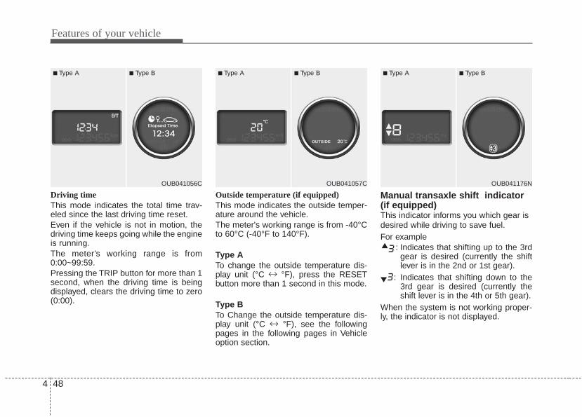
Features of your vehicle
484
Driving timeThis mode indicates the total time trav-eled since the last driving time reset.Even if the vehicle is not in motion, thedriving time keeps going while the engineis running.The meter’s working range is from0:00~99:59.Pressing the TRIP button for more than 1second, when the driving time is beingdisplayed, clears the driving time to zero(0:00).
Outside temperature (if equipped)This mode indicates the outside temper-ature around the vehicle.The meter's working range is from -40°Cto 60°C (-40°F to 140°F).
Type ATo change the outside temperature dis-play unit (°C ↔ °F), press the RESETbutton more than 1 second in this mode.
Type BTo Change the outside temperature dis-play unit (°C ↔ °F), see the followingpages in the following pages in Vehicleoption section.
Manual transaxle shift indicator(if equipped)This indicator informs you which gear isdesired while driving to save fuel.For example
: Indicates that shifting up to the 3rdgear is desired (currently the shiftlever is in the 2nd or 1st gear).
: Indicates that shifting down to the3rd gear is desired (currently theshift lever is in the 4th or 5th gear).
When the system is not working proper-ly, the indicator is not displayed.
OUB041056C
■ Type A ■ Type B
OUB041057C
■ Type A ■ Type B
OUB041176N
■ Type A ■ Type B

4 49
Features of your vehicle
Automatic transaxle shift positionindicator (if equipped) The indicator displays which automatictransaxle shift lever is selected.
Illumination intensityThe illumination intensity of the instru-ment panel is shown when adjusting itwith the illumination control switch.For more details, refer to “Instrumentpanel illumination” in section 4.
User Settings (only for Type Bcluster, if equipped)1. Stop the vehicle with the ignition switch
in the ON position or engine running.2. Press the TRIP button until the User
setting is displayed.3. With the User setting displayed, press
the TRIP button for 2 seconds.4. You can change the item by pressing
the TRIP button and select an item bypressing the RESET button.
OUB041177N
■ Type A ■ Type B
OUB041062
■ Type A ■ Type B
OUB041069
■ Type B
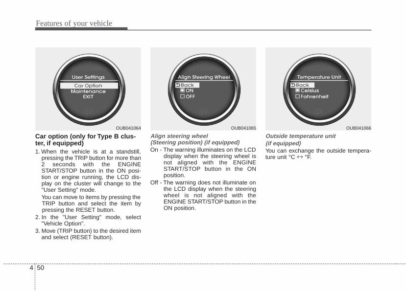
Features of your vehicle
504
Car option (only for Type B clus-ter, if equipped)1. When the vehicle is at a standstill,
pressing the TRIP button for more than2 seconds with the ENGINESTART/STOP button in the ON posi-tion or engine running, the LCD dis-play on the cluster will change to the"User Setting" mode.You can move to items by pressing theTRIP button and select the item bypressing the RESET button.
2. In the "User Setting" mode, select"Vehicle Option".
3. Move (TRIP button) to the desired itemand select (RESET button).
Align steering wheel (Steering position) (if equipped)On - The warning illuminates on the LCD
display when the steering wheel isnot aligned with the ENGINESTART/STOP button in the ONposition.
Off - The warning does not illuminate onthe LCD display when the steeringwheel is not aligned with theENGINE START/STOP button in theON position.
Outside temperature unit (if equipped)You can exchange the outside tempera-ture unit °C ↔ °F.
OUB041064 OUB041065 OUB041066

4 51
Features of your vehicle
LanguageChoose a language you prefer within theLCD display.
Maintenance system (only for Type B cluster,if equipped)The Maintenance system informs thedriver when to replace engine oil androtate tires.
Maintenance1. When the vehicle is at a standstill,
pressing the TRIP button for more than2 seconds with the ENGINE START/STOP button in the ON position orengine running, the LCD display onthe cluster will change to the "UserSetting" mode.You can move to the items by pressingthe TRIP button and select the item bypressing the RESET button.
2. In the "User Setting" mode select"Maintenance".
OUB041067 OUB041068 OUB041069

Features of your vehicle
524
Maintenance schedule1. Select the desired engine oil (tire rota-
tion) maintenance schedule.2. If finished, you can come out of the
Maintenance mode by pressing theTRIP button for more than 2 seconds.
Engine Oil(Tire Rotation) ServiceRequired1. If service is required, the message will
be displayed.
2. If you would like to reset or inactivatethe maintenance system press theRESET button for more than 1 second.The display will change to "Engine OilService Message" mode.You can move to items by pressing theTRIP button and select the desireditem by pressing the RESET button.
OUB041070 OUB041071 OUB041072

4 53
Features of your vehicle
Warnings and indicatorsAll warning lights are checked by turningthe ignition switch ON (do not start theengine). Any light that does not illuminateshould be checked by an authorized Kiadealer.After starting the engine, check to makesure that all warning lights are off. If anywarning lights are still on, this indicates asituation that needs attention. Whenreleasing the parking brake, the brakesystem warning light should go off. Thefuel warning light will stay on if the fuellevel is low.
Air bag warning light
This warning light will illuminate forapproximately 6 seconds each time youturn the ignition switch to the ON posi-tion.This light also comes on when theSupplement Restraint System (SRS) isnot working properly. If the air bag warn-ing light does not come on, or continu-ously remains on after operating forabout 6 seconds when you turned theignition switch to the ON position or start-ed the engine, or if it comes on whiledriving, have the SRS inspected by anauthorized Kia dealer.
Anti-lock brake system(ABS) warning light (if equipped)
This warning light illuminates if the igni-tion switch is turned ON and goes off inapproximately 3 seconds if the system isoperating normally.If the ABS warning light remains on,comes on while driving, or does notcome on when the ignition switch isturned to the ON position, this indicatesthat the ABS may have malfunctioned.If this occurs, have your vehicle checkedby an authorized Kia dealer as soon aspossible. The normal braking system willstill be operational, but without the assis-tance of the anti-lock brake system.
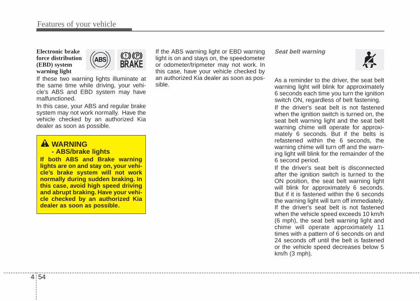
Features of your vehicle
544
Electronic brakeforce distribution(EBD) systemwarning lightIf these two warning lights illuminate atthe same time while driving, your vehi-cle’s ABS and EBD system may havemalfunctioned.In this case, your ABS and regular brakesystem may not work normally. Have thevehicle checked by an authorized Kiadealer as soon as possible.
If the ABS warning light or EBD warninglight is on and stays on, the speedometeror odometer/tripmeter may not work. Inthis case, have your vehicle checked byan authorized Kia dealer as soon as pos-sible.
Seat belt warning
As a reminder to the driver, the seat beltwarning light will blink for approximately6 seconds each time you turn the ignitionswitch ON, regardless of belt fastening.If the driver's seat belt is not fastenedwhen the ignition switch is turned on, theseat belt warning light and the seat beltwarning chime will operate for approxi-mately 6 seconds. But if the belts isrefastened within the 6 seconds, thewarning chime will turn off and the warn-ing light will blink for the remainder of the6 second period.If the driver's seat belt is disconnectedafter the ignition switch is turned to theON position, the seat belt warning lightwill blink for approximately 6 seconds.But if it is fastened within the 6 secondsthe warning light will turn off immediately.If the driver's seat belt is not fastenedwhen the vehicle speed exceeds 10 km/h(6 mph), the seat belt warning light andchime will operate approximately 11times with a pattern of 6 seconds on and24 seconds off until the belt is fastenedor the vehicle speed decreases below 5km/h (3 mph).
WARNING- ABS/brake lights
If both ABS and Brake warninglights are on and stay on, your vehi-cle’s brake system will not worknormally during sudden braking. Inthis case, avoid high speed drivingand abrupt braking. Have your vehi-cle checked by an authorized Kiadealer as soon as possible.

4 55
Features of your vehicle
Turn signal indicator
The blinking green arrows on the instru-ment panel show the direction indicatedby the turn signals. If the arrow comes onbut does not blink, blinks more rapidlythan normal, or does not illuminate at all,it indicates a malfunction in the turn sig-nal system.You should consult your deal-er for repairs.This indicator also blinks when the haz-ard warning switch is turned on.
High beam indicator
This indicator illuminates when the head-lights are on and in the high beam posi-tion or when the turn signal lever is pulledinto the Flash-to-Pass position.
Front fog light indicator (if equipped)
The indicator illuminates when the frontfog lights ON.
Tail light indicator
This indicator illuminates when the taillights are on.
Engine oil pressure warning light
This warning light indicates the engine oilpressure is low.If the warning light illuminates while driv-ing:1. Drive safely to the side of the road and
stop.2. With the engine off, check the engine
oil level. If the level is low, add oil asrequired.
If the warning light remains on afteradding oil or if oil is not available, call anauthorized Kia dealer.
CAUTION - Engine damageIf the engine is not stopped imme-diately after the engine oil pressurewarning light is illuminated andstays on while the engine is run-ning, serious engine damage mayresult.

Features of your vehicle
564
The oil pressure warning light comes onwhenever there is insufficient oil pres-sure. In normal operation, it should comeon when the ignition switch is turned on,then go out when the engine is started. Ifthe oil pressure warning light stays onwhile the engine is running, there is aserious malfunction.
Parking brake & brakefluid warning light
Parking brake warning This warning light illuminates for 3 sec-onds after the ignition switch is turned tothe ON position and then it will go out.Also, this light illuminates when the park-ing brake is applied with the ignitionswitch in the START or ON position. Thewarning light should go out when theparking brake is released.
Low brake fluid level warningIf the warning light remains on, it mayindicate that the brake fluid level in thereservoir is low.If the warning light remains on:1. Drive carefully to the nearest safe
location and stop your vehicle.2. With the engine stopped, check the
brake fluid level immediately and addfluid as required. Then check all brakecomponents for fluid leaks.
3. Do not drive the vehicle if leaks arefound, the warning light remains on orthe brakes do not operate properly.Have the vehicle towed to any author-ized Kia dealer for a brake systeminspection and necessary repairs.
Your vehicle is equipped with dual-diago-nal braking systems. This means you stillhave braking on two wheels even if oneof the dual systems should fail. With onlyone of the dual systems working, morethan normal pedal travel and greaterpedal pressure are required to stop thevehicle. Also, the vehicle will not stop inas short a distance with only a portion ofthe brake system working. If the brakesfail while you are driving, shift to a lowergear for additional engine braking andstop the vehicle as soon as it is safe to doso.To check bulb operation, check whetherthe parking brake and brake fluid warninglight illuminates when the ignition switchis in the ON position.

4 57
Features of your vehicle
Engine coolant tempera-ture warning light (for Type A cluster)
The warning light shows the temperatureof the engine coolant when the ignitionswitch is ON.The warning light illuminates if the tem-perature of the engine coolant is above120±3°C (248±5.5°F).Do not continue driving with an overheat-ed engine. If your vehicle overheats, referto “Overheating” in the Index.
✽✽ NOTICE - Coolant temperatureIf the engine coolant temperature warn-ing light illuminates, it indicates over-heating that may damage the engine.
Charging system warninglight
This warning light indicates a malfunctionof either the generator or electricalcharging system.If the warning light illuminates while thevehicle is in motion:1. Drive to the nearest safe location.2. With the engine off, check the genera-
tor drive belt for looseness or break-age.
3. If the belt is adjusted properly, a prob-lem exists somewhere in the electricalcharging system. Have an authorizedKia dealer correct the problem as soonas possible.
Trunk lid (or tailgate) openwarning light
This warning light illuminates when thetrunk lid (or tailgate) is not closed secure-ly with the ignition switch in any position.
Door ajar warning light
This warning light illuminates when adoor is not closed securely with the igni-tion switch in any position.

Features of your vehicle
584
Immobilizer indicator
If any of the following occurs in a vehicleequipped with the smart key, the immobi-lizer indicator illuminates, blinks or goesoff.• When the smart key is in the vehicle, if
the ENGINE START/STOP button is inthe ACC or ON position, the indicatorwill illuminate for a few minutes to indi-cate that you are able to start theengine. However, when the smart keyis not in the vehicle, if the ENGINESTART/STOP button is pressed, theindicator will blink for a few minutes toindicate that you are not able to startthe engine.
• When the ENGINE START/STOP but-ton changes to the ON position fromthe ACC position without the smart keyin the vehicle, the indicator blinks for afew minutes to indicate that you are notable to start the engine.
• When the battery is weak, if theENGINE START/STOP button ispressed, the indicator will blink and youare not able to start the engine.However, you are able to start theengine by inserting the smart key inthe smart key holder. If the smart keysystem related parts have a problem,the indicator will blink.
Low fuel level warning light
This warning light indicates the fuel tankis nearly empty. When it comes on, youshould add fuel as soon as possible.Driving with the fuel level warning light onor with the fuel level below “E” can causethe engine to misfire and damage thecatalytic converter (if equipped).

4 59
Features of your vehicle
Malfunction indicator lamp(MIL) (check engine light)
This indicator is part of the EngineControl System which monitors variousemission control system components. Ifthis indicator illuminates while driving, itindicates that a potential malfunction hasbeen detected somewhere in the emis-sion control system.This indicator will also illuminates whenthe ignition switch is turned to the ONposition, and will go off in a few secondsafter the engine is started. If it illuminateswhile driving, or does not illuminate whenthe ignition switch is turned to the ONposition, take your vehicle to the nearestauthorized Kia dealer and have the sys-tem checked.Generally, your vehicle will continue to bedrivable, but have the system checked byan authorized Kia dealer promptly.
ESC indicator (ElectronicStability Control)
The ESC indicator will illuminate whenthe ignition switch is turned ON, butshould go off after approximately 3 sec-onds. When the ESC is on, it monitorsthe driving conditions under normal driv-ing conditions, the ESC light will remainoff. When a slippery or low traction con-dition is encountered, the ESC will oper-ate, and the ESC indicator will blink toindicate the ESC is operating.If the ESC indicator stays on, the ESCmay have a malfunction. Take your car toan authorized Kia dealer and have thesystem checked.
CAUTION - MIL illumina-tion
• Prolonged driving with theEmission Control SystemMalfunction Indicator Light illumi-nated may cause damage to theemission control systems whichcould effect drivability and/or fueleconomy.
• If the Emission Control SystemMalfunction Indicator Light illumi-nates, potential catalytic converterdamage. This could result in lossof engine power. Have the EngineControl System inspected as soonas possible by an authorized Kiadealer.

Features of your vehicle
604
ESC OFF indicator
The ESC OFF indicator will illuminatewhen the ignition switch is turned ON,but should go off after approximately 3seconds. To switch to ESC OFF mode,press the ESC OFF button. The ESCOFF indicator will illuminate indicatingthe ESC is deactivated.
Low tire pressure telltale(if equipped)
The low tire pressure telltale comes onfor 3 seconds after the ignition key isturned to the "ON" position.If the warning light does not come on, orcontinuously remains on after coming onfor about 3 seconds when you turned theignition key to the "ON" position, the TirePressure Monitoring System is not work-ing properly. If this occurs, have yourvehicle checked by an Kia authorizeddealer as soon as possible.This warning light will also illuminate ifone or more of your tires is significantlyunder-inflated. You should stop andcheck your tires as soon as possible. Ifthe warning light illuminates while driv-ing, reduce vehicle speed immediatelyand stop the vehicle.Avoid hard braking and overcorrecting atthe steering wheel. Inflate the tires to theproper pressure as indicated on the vehi-cle’s tire information placard.
WARNING - Low tire pressure
Significantly low tire pressuremakes the vehicle unstable and cancontribute to loss of vehicle controland increased braking distances.Continued driving on tires with lowpressure will cause the tires tooverheat and fail.

4 61
Features of your vehicle
Cruise indicator (if equipped)CRUISE indicator
The indicator illuminates when the cruisecontrol system is enabled.The cruise indicator in the instrumentcluster is illuminated when the cruisecontrol ON/OFF button on the steeringwheel is pushed.The indicator goes off when the cruisecontrol ON/OFF button is pushed again.For more Information, refer to “Cruisecontrol system” in section 5.
Cruise SET indicator
The indicator illuminates when the cruisefunction switch (SET- or RES+) is ON.The cruise SET indicator in the instru-ment cluster illuminates when the cruisecontrol switch (SET- or RES+) is pushed.The cruise SET indicator does not illumi-nate when the cruise control switch(CANCEL) is pushed or the system isdisengaged.
Key reminder warning chime (if equipped)If the driver’s door is opened while theignition key is left in the ignition switch(ACC or LOCK position), the keyreminder warning chime will sound. Thisis to prevent you from locking your keysin the vehicle. The chime sounds until thekey is removed from the ignition switch orthe driver’s door is closed.
Electric power steering(EPS) system warning light(if equipped)
This warning light illuminates after theignition key is turned to the ON positionand then it will go off when the enginestarts.This light also comes on when the EPShas malfunctioned. If it comes on whiledriving, have your vehicle inspected byan authorized Kia dealer.
Fuel cap open warningindicator
This warning light indicates the fuel fillercap is not tighten securely.Always make sure that the fuel filler capis tight.
SETCRUISE
Features of your vehicle
624
ECOMINDER® indicator (if equipped)
The ECOMINDER® indicator is displayedto help you improve fuel efficiency whenyou are driving.• The ECOMINDER® indicator will turn
the ECO light green on the instrumentpanel when you are driving efficientlyin the ECO ON mode.If you don't want the indicator dis-played, you can turn the ECO ONmode to OFF mode by pressing theTRIP button.
• When the instant fuel consumptionmode(if equipped) is displayed on theLCD display or the system is not work-ing properly, the indicator turns off. Ifthe indicator turns off when the instantfuel consumption mode or ECO OFFmode is not selected, have the systemchecked by an authorized Kia dealeras soon as possible.
• Fuel efficiency depends on the driver'sdriving habit and road condition.
• The system stops operating when thetransaxle is in the P (Park), R(Reverse), N (Neutral) position orsports mode, or when the instant fuelconsumption mode is selected.
Auto stop indicator(if equipped)
This indicator will illuminate when theengine enters the Idle Stop mode of theISG (Idle Stop and Go) system.When the automatic starting occurs, theauto stop indicator on the cluster willblink for 5 seconds.
For more details, refer to the ISG (IdleStop and Go) system in chapter 5.
✽✽ NOTICEWhen the engine automatically starts bythe ISG system, some warning lights(ABS, ESC, ESC OFF, ESC or Parkingbrake warning light) may turn on for afew seconds. This happens because of the low batteryvoltage. It does not mean the system ismalfunctioning.
WARNING - ECOMINDER®
indicator Don't keep watching the “ECO”ECOMINDER® indicator while driv-ing. It may distract you while driv-ing and cause an accident.
ECO

4 63
Features of your vehicle
Key is not in vehicle
If the smart key is not in the vehicle andif any door is opened or closed with theengine start/stop button in the ACC, ON,or START position, the warning illumi-nates on the LCD display. Also, the chimesounds for 5 seconds when the smartkey is not in the vehicle and the door isclosed.Always have the smart key with you.
Key is not detected
If the smart key is not in the vehicle or isnot detected and you press the enginestart/stop button, the warning illuminateson the LCD display for 10 seconds. Also,the immobilizer indicator blinks for 10seconds.
Press start with smart key
If you press the engine start/stop buttonwhile the warning “Key is not detected” isilluminated, the warning “Press the startbutton with smart key” illuminates for 10seconds on the LCD display. Also, theimmobilizer indicator blinks for 10 sec-onds.
OUB041073 OUB041074 OUB041075
LCD display warning (if equipped)• For vehicle’s equipped with smart key system

Features of your vehicle
644
Low key battery
If the engine start/stop button changes tothe OFF position when the smart key inthe vehicle discharges, the warning illu-minates on the LCD display for about 10seconds. Also, the warning chimesounds once.Replace the battery with a new one.
Press brake pedal to start engine (for automatic transaxle)
If the engine start/stop button changes tothe ACC position twice by pressing thebutton repeatedly without depressing thebrake pedal, the warning illuminates onthe LCD display for about 10 seconds toindicate that you should depress thebrake pedal to start the engine.
Press clutch pedal to start engine (for manual transaxle)
If the engine start/stop button turns to theACC position twice by pressing the but-ton repeatedly without depressing theclutch pedal, the warning illuminates onthe LCD display for about 10 seconds toindicate that you should depress theclutch pedal to start the engine.
• For vehicle’s equipped with smart key system
OUB041076OUB041077 OUB041078

4 65
Features of your vehicle
Shift to "P" position(for automatic transaxle)
If you try to turn off the engine without theshift lever in the P (Park) position, theengine start/stop button will turn to theACC position. If the button is pressedonce more it will turn to the ON position.The warning illuminates on the LCD dis-play for about 10 seconds to indicate thatyou should press the engine start/stopbutton with the shift lever in the P (Park)position to turn off the engine.Also, the warning chime sounds for about10 seconds. (if equipped)
Press start button again
If you can not operate the enginestart/stop button when there is a problemwith the engine start/stop button system,the warning illuminates for 10 secondsand the chime sounds continuously toindicate that you could start the engineby pressing the engine start/stop buttononce more.The chime will stop if the enginestart/stop button system works normallyor the theft alarm system is armed.If the warning illuminates each time youpress the engine start/stop button, takeyour vehicle to an authorized Kia dealerand have the system checked.
Shift to "P" or "N" to start the engine (for automatic transaxle)
If you try to start the engine with the shiftlever not in the P(Park) or N(Neutral)position, the warning illuminates forabout 10 seconds on the LCD display.You can also start the engine with theshift lever in the N(Neutral) position, butfor your safety start the engine with theshift lever in the P(Park) position.
OUB041080OUB041081
• For vehicle’s equipped with smart key system
OUB041079

Features of your vehicle
664
Press start button while turn steering
If the steering wheel does not unlock nor-mally when the engine start/stop buttonis pressed, the warning illuminates for 10seconds on the LCD display. Also, thewarning chime sounds once and theengine start/stop button light blinks for 10seconds.When you are warned, press the enginestart/stop button while turning the steer-ing wheel right and left.
Check steering wheel lock system
If the steering wheel does not lock nor-mally when the engine start/stop buttonchanges to the OFF position, the warningilluminates for 10 seconds on the LCDdisplay. Also, the warning chime soundsfor 3 seconds and the engine start/stopbutton light blinks for 10 seconds.
OUB041082 OUB041084

4 67
Features of your vehicle
Check stop lamp fuse (if equipped)
When the stop lamp fuse is disconnect-ed, the warning illuminates for 10 sec-onds on the LCD display.Replace the fuse with a new one. If thatis not possible you can start the engineby pressing the engine start/stop buttonfor 10 seconds in ACC.
Door open! (if equipped)
It displays the corresponding door or tail-gate that is not closed securely.
Fuel cap open warning (if equipped)
This warning light indicates the fuel fillercap is not tight securely.Always make sure that the fuel filler capis tight.
OUB041085 OUB041087 OUB041170

Features of your vehicle
684
Align steering wheel (if equipped)
If you start the engine when the steeringwheel is turned 90 degrees to the leftafter a couple of seconds, “Align steeringwheel” illuminates on the LCD display for5 seconds.Turn the steering wheel to the right andmake it turned to the left less than 30degrees.
Align steering wheel (if equipped)
If you start the engine when the steeringwheel is turned 90 degrees to the rightafter a couple of seconds, “Align steeringwheel” illuminates on the LCD display for5 seconds.Turn the steering wheel to the left andmake it turned to the right less than 30degrees.
OUB041088 OUB041089

4 69
Features of your vehicle
The rearview camera will activate whenthe back-up light is ON with the ignitionswitch ON and the shift lever in the R(Reverse) position.This system is a supplemental systemthat shows behind the vehicle throughthe uvo audio or navigation display back-ing-up.
Always keep the camera lens clean. Iflens is covered with foreign matter, thecamera may not operate normally.
REARVIEW CAMERA (IF EQUIPPED)
WARNING - Rearview camera
The rear view camera is not a safe-ty device. It only serves to assistthe driver in identifying objectsdirectly behind the middle of thevehicle. The camera does NOTcover the complete area behind thevehicle. While the camera's displayis generally accurate, objects canbe much closer than they appear inthe display screen and can be dis-torted in both size and proportion.
WARNING - Backing &using camera
Never rely solely on the rear viewcamera when backing. You mustalways use methods of viewing thearea behind you including lookingover both shoulders as well as con-tinuously checking all three rearview mirrors. Due to the difficulty ofensuring that the area behind youremains clear, always back slowlyand stop immediately if you evensuspect that a person, and espe-cially a child, might be behind you.
OUB041092
OUB041093
■ Type A
■ Type B

Features of your vehicle
704
The hazard warning flasher should beused whenever you find it necessary tostop the car in a hazardous location.When you must make such an emer-gency stop, always pull off the road as faras possible.The hazard warning lights are turned onby pushing in the hazard switch. Bothturn signal lights will blink. The hazardwarning lights will operate even thoughthe key is not in the ignition switch.To turn the hazard warning lights off,push the switch again.
Battery saver function • The purpose of this feature is to pre-
vent the battery from being dis-charged. The system automaticallyturns off the parking lights when thedriver removes the ignition key andopens the driver- side door.
• With this feature, the parking lights willturn off automatically if the driver parkson the side of the road at night.If necessary, to keep the lights onwhen the ignition key is removed, per-form the following :1) Open the driver-side door.2) Turn the parking lights OFF and ON
again using the light switch on thesteering column.
Daytime running lightDaytime Running Lights (DRL) can makeit easier for others to see the front of yourvehicle during the day. DRL can be help-ful in many different driving conditions,and it is especially helpful after dawn andbefore sunset.The DRL system turns OFF when:1. The headlight are ON.2. Engine stops.
Lighting controlThe light switch has a Headlight and aParking light position.To operate the lights, turn the knob at theend of the control lever to one of the fol-lowing positions:(1) OFF position(2) Parking light position(3) Headlight position(4) Auto light position (if equipped)
HAZARD WARNING FLASHER
OXM049110
LIGHTING
OUB041094

4 71
Features of your vehicle
Parking light position ( )When the light switch is in the parkinglight position (1st position), the tail, posi-tion, license and instrument panel lightswill turn ON.
Headlight position ( )When the light switch is in the headlightposition (2nd position) the head, tail,position, license and instrument panellights will turn ON.The ignition switch must be in the ONposition to turn on the headlights.
Auto light position (if equipped)When the light switch is in the AUTO lightposition, the taillights and headlights willturn ON or OFF automatically dependingon the amount of light outside the vehi-cle.Never place anything over sensor (1)located on the instrument panel. This willensure better auto-light system control.Don’t clean the sensor using a windowcleaner. The cleaner may leave a lightfilm which could interfere with sensoroperation.If your vehicle has window tint or othertypes of metallic coating on the frontwindshield, the Auto light system may notwork properly.
OAM049041 OAM049042 OFS040084

Features of your vehicle
724
High beam operation To turn on the high beam headlights, pushthe lever away from you. Pull it back forlow beams.The high-beam indicator will light whenthe headlight high beams are switched on.To prevent the battery from being dis-charged, do not leave the lights on for aprolonged time while the engine is notrunning.
To flash the headlights, pull the levertowards you. It will return to the normal(low-beam) position when released. Theheadlight switch does not need to be onto use this flashing feature.
Turn signals and lane change sig-nalsThe ignition switch must be on for theturn signals to function. To turn on theturn signals, move the lever up or down(A). The green arrow indicators on theinstrument panel indicate which turn sig-nal is operating. They will self-cancelafter a turn is completed. If the indicatorcontinues to flash after a turn, manuallyreturn the lever to the OFF position.To signal a lane change, move the turnsignal lever slightly and hold it in position(B). The lever will return to the OFF posi-tion when released.
OAM049044
WARNING - High beams Do not use high beam when thereare other vehicles. Using highbeam could obstruct the other dri-ver's vision.
OAM049045OAM049043

4 73
Features of your vehicle
If an indicator stays on and does notflash or if it flashes abnormally, one of theturn signal bulbs may be burned out andwill require replacement.If an indicator flash is abnormally quick orslow, a bulb may be burned out or have apoor electrical connection in the circuit.
Front fog light (if equipped) Fog lights are used to provide improvedvisibility when visibility is poor due to fog,rain or snow etc. The fog lights will turnon when the fog light switch (1) is turnedto the on position after the headlights areturned on.To turn off the fog lights, turn the switch(1) to the off position.When in operation, the fog lights con-sume large amounts of vehicle electricalpower. Only use the fog lights when visi-bility is poor.
OAM049046N

Features of your vehicle
744
A : Wiper speed control (front)· HI – High wiper speed· LO – Low wiper speed· INT – Intermittent wipe · AUTO* – Automatic control wipe· OFF – Off· MIST – Single wipe
B : Intermittent control wipe timeadjustment
C : Wash with brief wipes (front)
D : Rear wiper/washer control· ON – Continuous wipe· INT – Intermittent wipe · OFF – Off
E : Wash with brief wipes (rear)
* : if equipped
WIPERS AND WASHERSFront Rear (if equipped)
OAM049100L/OAM049048N
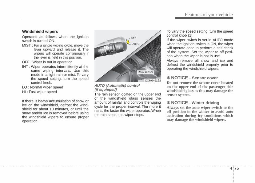
4 75
Features of your vehicle
Windshield wipers Operates as follows when the ignitionswitch is turned ON.MIST : For a single wiping cycle, move the
lever upward and release it. Thewipers will operate continuously ifthe lever is held in this position.
OFF : Wiper is not in operation INT : Wiper operates intermittently at the
same wiping intervals. Use thismode in a light rain or mist. To varythe speed setting, turn the speedcontrol knob.
LO : Normal wiper speed HI : Fast wiper speed
If there is heavy accumulation of snow orice on the windshield, defrost the wind-shield for about 10 minutes, or until thesnow and/or ice is removed before usingthe windshield wipers to ensure properoperation.
AUTO (Automatic) control (if equipped)The rain sensor located on the upper endof the windshield glass senses theamount of rainfall and controls the wipingcycle for the proper interval. The more itrains, the faster the wiper operates. Whenthe rain stops, the wiper stops.
To vary the speed setting, turn the speedcontrol knob (1).If the wiper switch is set in AUTO modewhen the ignition switch is ON, the wiperwill operate once to perform a self-checkof the system. Set the wiper to off posi-tion when the wiper is not in use.Always remove all snow and ice anddefrost the windshield properly prior tooperating the windshield wipers.
✽✽ NOTICE - Sensor coverDo not remove the sensor cover locatedon the upper end of the passenger sidewindshield glass as this may damage thesensor system.
✽✽ NOTICE - Winter drivingAlways set the auto wiper switch to theoff position in the winter to avoid autoactivation during icy conditions whichmay damage the windshield wipers.
OXM049123
Rain sensor

Features of your vehicle
764
Windshield washers In the OFF position, pull the lever gentlytoward you to spray washer fluid on thewindshield and to run the wipers 1-3cycles.Use this function when the windshield isdirty.The spray and wiper operation will con-tinue until you release the lever. If thewasher does not work, check the washerfluid level.If the fluid level is not sufficient, you willneed to add appropriate non-abrasivewindshield washer fluid to the washerreservoir.The reservoir filler neck is located in thefront of the engine compartment on thepassenger side.
CAUTION - Washer pumpTo prevent possible damage to thewasher pump, do not operate thewasher when the fluid reservoir isempty.
WARNING - Obscured visibility
Do not use the washer in freezingtemperatures without first warmingthe windshield with the defrosters;the washer solution could freeze onthe windshield and obscure yourvision.
CAUTION - Wiper positionWhen washing the vehicle, set thewiper switch in the off position tostop the auto wiper operation.The wiper may operate and be dam-aged if the switch is set in the AUTOmode while washing the vehicle.

4 77
Features of your vehicle
Rear window wiper and washerswitchThe rear window wiper and washerswitch is located at the end of the wiperand washer switch lever. Turn the switchto the desired position to operate the rearwiper and washer.ON - Normal wiper operation INT - Intermittent wiper operation
(if equipped)
OFF - Wiper is not in operation
Push the lever away from you to sprayrear washer fluid and to run the rearwipers 1~3 cycles. The spray and wiperoperation will continue until you releasethe lever.
CAUTION - Wipers & windshields
• To prevent possible damage tothe wipers or windshield, do notoperate the wipers when thewindshield is dry.
• To prevent damage to the wiperblades, do not use gasoline,kerosene, paint thinner, or othersolvents on or near them.
• To prevent damage to the wiperarms and other components, donot attempt to move the wipersmanually.
OAM049103N OXM049125

Features of your vehicle
784
Do not use the interior lights for extendedperiods when the engine is not running.It may cause battery discharge.
Map lamp (if equipped) 1. Push the lens to turn the light on or off.2. DOOR : The light comes on or goes
off when a door is opened orclosed.
3. OFF (Door switch is not pressed) :The light stays off at all times even whena door is opened.When the light is turned on with the lenspressed, the light is not turned off evenwith the switch in the OFF position.
Room lamp1. ON : The light stays on at all times.2. DOOR : The light comes on or off
when a door is opened orclosed.
3. OFF : The light stays off at all timeseven when a door is opened.
Do not leave the switch in the ON posi-tion for an extended period of time whenthe vehicle is not running.
INTERIOR LIGHT
WARNING - Interior lightDo not use the interior lights whendriving in the dark. The glare fromthe interior lights may obstructyour view and cause an accident.
OAM049052 OUB041098

4 79
Features of your vehicle
Luggage room lampThe luggage room lamp comes on whenthe tailgate is opened.To prevent unnecessary charging systemdrain, close the tailgate securely afterusing the luggage room.
Vanity mirror lamp (if equipped)Push the switch to turn the light on or off.• : The lamp will turn on if this button
is pressed.• : The lamp will turn off if this button
is pressed.Always have the switch in the off positionwhen the vanity mirror lamp is not in use.If the sunvisor is closed without the lampoff, it may discharge the battery or dam-age the sunvisor.
Glove box lampThe glove box lamp comes on when theglove box is opened.To prevent unnecessary charging systemdrain, close the glove box securely afterusing the glove box.
OUB041099 OLM049105 OUB041100
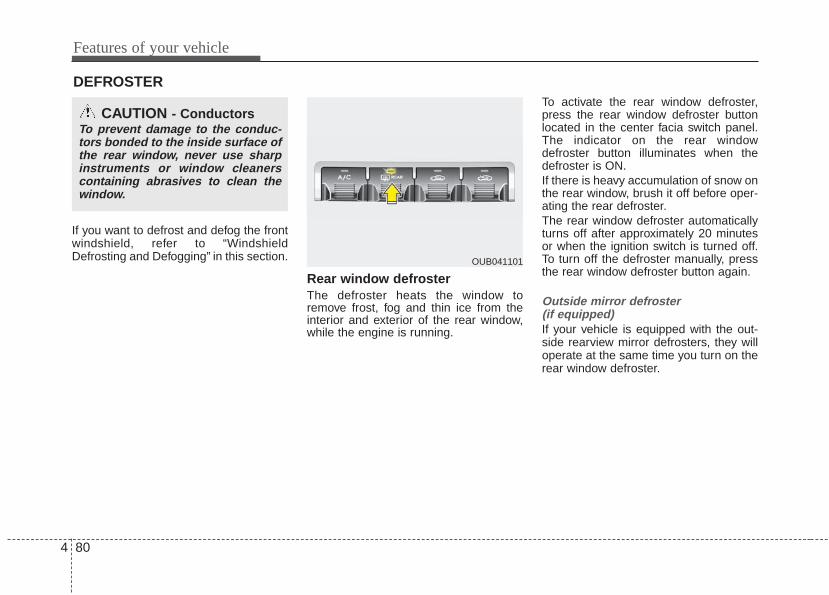
Features of your vehicle
804
If you want to defrost and defog the frontwindshield, refer to “WindshieldDefrosting and Defogging” in this section.
Rear window defrosterThe defroster heats the window toremove frost, fog and thin ice from theinterior and exterior of the rear window,while the engine is running.
To activate the rear window defroster,press the rear window defroster buttonlocated in the center facia switch panel.The indicator on the rear windowdefroster button illuminates when thedefroster is ON.If there is heavy accumulation of snow onthe rear window, brush it off before oper-ating the rear defroster.The rear window defroster automaticallyturns off after approximately 20 minutesor when the ignition switch is turned off.To turn off the defroster manually, pressthe rear window defroster button again.
Outside mirror defroster (if equipped)If your vehicle is equipped with the out-side rearview mirror defrosters, they willoperate at the same time you turn on therear window defroster.
DEFROSTER
CAUTION - ConductorsTo prevent damage to the conduc-tors bonded to the inside surface ofthe rear window, never use sharpinstruments or window cleanerscontaining abrasives to clean thewindow.
OUB041101

4 81
Features of your vehicle
MANUAL CLIMATE CONTROL SYSTEM
1. Fan speed control knob
2. Mode selection knob
3. Temperature control knob
4. Air conditioning button (if equipped)
5. Rear window defroster button
6. Air intake control button
OUB041103

Features of your vehicle
824
Heating and air conditioning1. Start the engine.2. Set the mode to the desired position.
To improve the effectiveness of heat-ing and cooling :- Heating:- Cooling:
3. Set the temperature control to thedesired position.
4. Set the air intake control to the outside(fresh) air or recirculated air position.
5. Set the fan speed control to thedesired speed.
6. If air conditioning is desired, turn theair conditioning system (if equipped)on.
OUB041104N

4 83
Features of your vehicle
Mode selectionThe mode selection knob controls thedirection of the air flow through the venti-lation system.Air can be directed to the floor, dash-board outlets, or windshield. Six symbolsare used to represent Face, Bi-Level,Floor, Floor-Defrost and Defrost air posi-tion.
Face-Level (B, D)
Air flow is directed toward the upper bodyand face. Additionally, each outlet can becontrolled to direct the air dischargedfrom the outlet.
Bi-Level (B, D, E, C)
Air flow is directed towards the face andthe floor.
Floor-Level (C, A, D, E)
Most of the air flow is directed to thefloor, with a small amount of the air beingdirected to the windshield and side win-dow defrosters.
Floor/Defrost-Level (A, C, D, E)
Most of the air flow is directed to the floorand the windshield with a small amountdirected to the side window defrosters.
Defrost-Level (A, D)
Most of the air flow is directed to thewindshield with a small amount of airdirected to the side window defrosters.OUB041105

Features of your vehicle
844
MAX A/C-Level (B, D) (if equipped)The MAX A/C mode is used to cool theinside of the vehicle faster.In this mode, the air conditioning and therecirculated air position will be selectedautomatically.
Instrument panel ventsThe outlet vents can be opened or closedseparately using the thumbwheel.Also, you can adjust the direction of airdelivered from these vents using the ventcontrol lever as shown.
Temperature controlThe temperature control knob allows youto control the temperature of the air flow-ing from the ventilation system. Tochange the air temperature in the pas-senger compartment, turn the knob tothe right for warm air or left for cooler air.
OUB041107OUB041106 OUB041108

4 85
Features of your vehicle
Air intake control This is used to select outside (fresh) airposition or recirculated air position.To change the air intake control position,push the control button.
Recirculated air position The indicator light on thebutton illuminates when therecirculated air position isselected.With the recirculated airposition selected, air frompassenger compartmentwill be drawn through theheating system and heatedor cooled according to thefunction selected.
Outside (fresh) air position The indicator light on thebutton will not illuminatewhen the outside (fresh) airposition is selected.With the outside (fresh) airposition selected, airenters the vehicle from out-side and is heated orcooled according to thefunction selected.
Prolonged operation of the heater in therecirculated air position (without air con-ditioning selected) may cause fogging ofthe windshield and side windows and theair within the passenger compartmentmay become stale.In addition, prolonged operation of the airconditioning with the recirculated airposition selected will result in excessive-ly dry air in the passenger compartment.
OUB041109 WARNING - Recirculatedair
Continuous use of the climate con-trol system in the recirculated airposition can cause drowsiness orsleepiness, and loss of vehicle con-trol. Set the air intake control to theoutside (fresh) air position as muchas possible while driving.
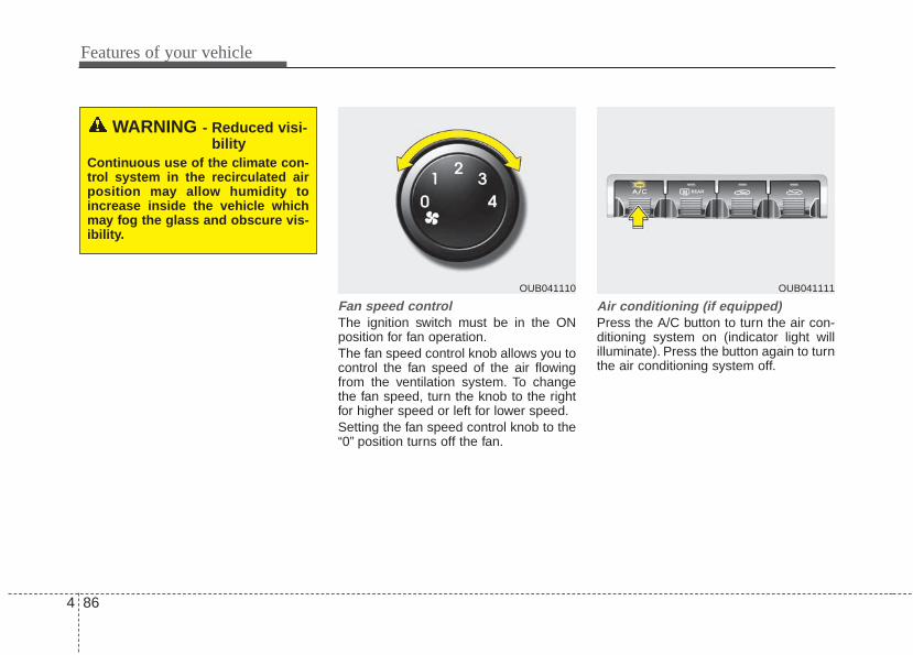
Features of your vehicle
864
Fan speed controlThe ignition switch must be in the ONposition for fan operation.The fan speed control knob allows you tocontrol the fan speed of the air flowingfrom the ventilation system. To changethe fan speed, turn the knob to the rightfor higher speed or left for lower speed.Setting the fan speed control knob to the“0” position turns off the fan.
Air conditioning (if equipped) Press the A/C button to turn the air con-ditioning system on (indicator light willilluminate). Press the button again to turnthe air conditioning system off.
WARNING - Reduced visi-bility
Continuous use of the climate con-trol system in the recirculated airposition may allow humidity toincrease inside the vehicle whichmay fog the glass and obscure vis-ibility.
OUB041110 OUB041111
4 87
Features of your vehicle
System operationVentilation1. Set the mode to the position.2. Set the air intake control to the outside
(fresh) air position.3. Set the temperature control to the
desired position.4. Set the fan speed control to the
desired speed.
Heating1. Set the mode to the position.2. Set the air intake control to the outside
(fresh) air position.3. Set the temperature control to the
desired position.4. Set the fan speed control to the
desired speed.5. If dehumidified heating is desired, turn
the air conditioning system (ifequipped) on.
• If the windshield fogs up, set the modeto the , position.
Operation Tips• To prevent dust or unpleasant fumes
from entering the vehicle through theventilation system, temporarily set theair intake control to the recirculated airposition. Be sure to return the controlto the fresh air position when the irrita-tion has passed to keep fresh air in thevehicle. This will help keep the driveralert and comfortable.
• Air for the heating/cooling system isdrawn in through the grilles just aheadof the windshield. Care should betaken that these are not blocked byleaves, snow, ice or other obstructions.
• To prevent interior fog on the wind-shield, set the air intake control to thefresh air position and fan speed to thedesired position, turn on the air condi-tioning system, and adjust the temper-ature control to desired temperature.
Air conditioning (if equipped) Kia Air Conditioning Systems are filledwith environmentally friendly R-134a refrigerant which does not dam-age the ozone layer.1. Start the engine. Push the air condi-
tioning button.2. Set the mode to the position.3. Set the air intake control to the recir-
culated air position. However, pro-longed operation of the reticulated airposition will excessively dry the air. Inthis case, change the air position.
4. Adjust the fan speed control and tem-perature control to maintain maximumcomfort.
• When maximum cooling is desired, setthe temperature control to the extremeleft position, set the mode control tothe MAX A/C position, then set the fanspeed control to the highest speed.

Features of your vehicle
884
Air conditioning system operation tips • If the vehicle has been parked in direct
sunlight during hot weather, open thewindows for a short time to let the hotair inside the vehicle escape.
• To help reduce moisture inside of thewindows on rainy or humid days,decrease the humidity inside the vehi-cle by operating the air conditioningsystem.
• During air conditioning system opera-tion, you may occasionally notice aslight change in engine speed as theair conditioning compressor cycles.This is a normal system operationcharacteristic.
• Use the air conditioning system everymonth only for a few minutes to ensuremaximum system performance.
• When using the air conditioning sys-tem, you may notice clear water drip-ping (or even puddling) on the groundunder the passenger side of the vehi-cle. This is a normal system operationcharacteristic.
• Operating the air conditioning systemin the recirculated air position providesmaximum cooling, however, continualoperation in this mode may cause theair inside the vehicle to become stale.
• During cooling operation, you mayoccasionally notice a misty air flowbecause of rapid cooling and humid airintake. This is a normal system opera-tion characteristic.
CAUTION - Excessive ACWhile using the air conditioningsystem, monitor the temperaturegauge closely while driving up hillsor in heavy traffic when outsidetemperatures are high. Air condi-tioning system operation maycause engine overheating andpotential engine damage. Continueto use the blower fan but turn theair conditioning system off if thetemperature gauge indicatesengine overheating.
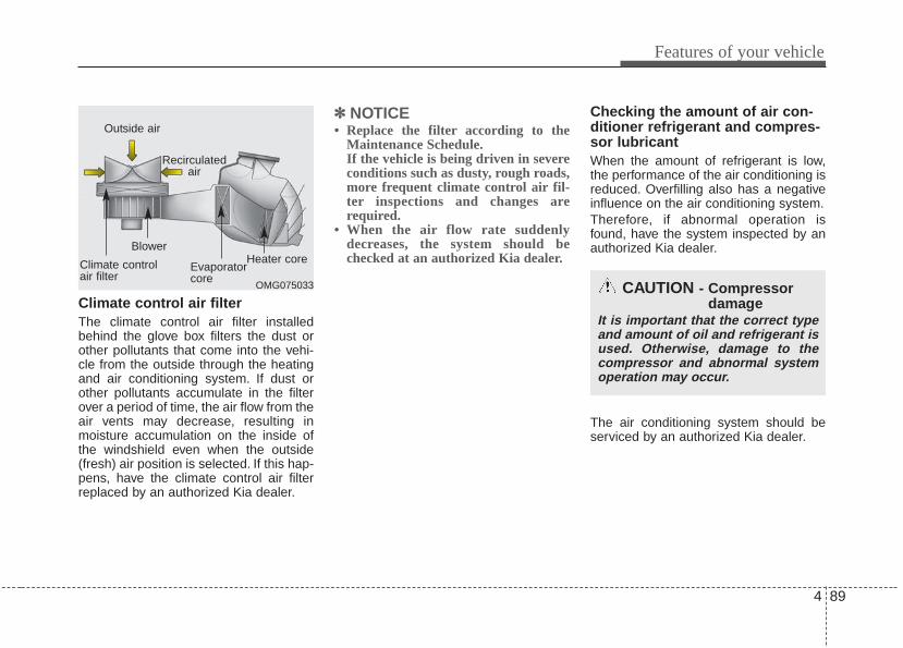
4 89
Features of your vehicle
Climate control air filterThe climate control air filter installedbehind the glove box filters the dust orother pollutants that come into the vehi-cle from the outside through the heatingand air conditioning system. If dust orother pollutants accumulate in the filterover a period of time, the air flow from theair vents may decrease, resulting inmoisture accumulation on the inside ofthe windshield even when the outside(fresh) air position is selected. If this hap-pens, have the climate control air filterreplaced by an authorized Kia dealer.
✽✽ NOTICE• Replace the filter according to the
Maintenance Schedule.If the vehicle is being driven in severeconditions such as dusty, rough roads,more frequent climate control air fil-ter inspections and changes arerequired.
• When the air flow rate suddenlydecreases, the system should bechecked at an authorized Kia dealer.
Checking the amount of air con-ditioner refrigerant and compres-sor lubricantWhen the amount of refrigerant is low,the performance of the air conditioning isreduced. Overfilling also has a negativeinfluence on the air conditioning system.Therefore, if abnormal operation isfound, have the system inspected by anauthorized Kia dealer.
The air conditioning system should beserviced by an authorized Kia dealer.
OMG075033
Outside air
Recirculatedair
Climate controlair filter
Blower
Evaporatorcore
Heater core
CAUTION - Compressordamage
It is important that the correct typeand amount of oil and refrigerant isused. Otherwise, damage to thecompressor and abnormal systemoperation may occur.
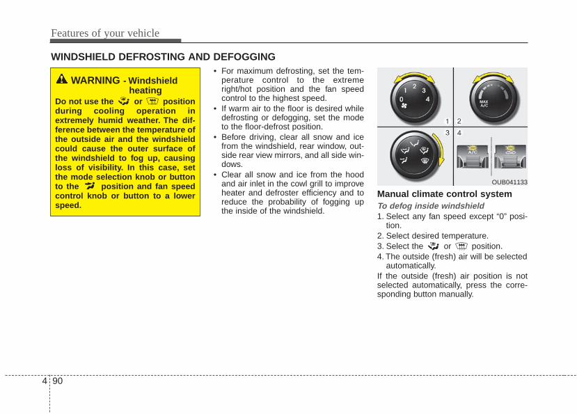
Features of your vehicle
904
WINDSHIELD DEFROSTING AND DEFOGGING• For maximum defrosting, set the tem-
perature control to the extremeright/hot position and the fan speedcontrol to the highest speed.
• If warm air to the floor is desired whiledefrosting or defogging, set the modeto the floor-defrost position.
• Before driving, clear all snow and icefrom the windshield, rear window, out-side rear view mirrors, and all side win-dows.
• Clear all snow and ice from the hoodand air inlet in the cowl grill to improveheater and defroster efficiency and toreduce the probability of fogging upthe inside of the windshield.
Manual climate control systemTo defog inside windshield 1. Select any fan speed except “0” posi-
tion.2. Select desired temperature.3. Select the or position.4. The outside (fresh) air will be selected
automatically.If the outside (fresh) air position is notselected automatically, press the corre-sponding button manually.
WARNING - Windshieldheating
Do not use the or positionduring cooling operation inextremely humid weather. The dif-ference between the temperature ofthe outside air and the windshieldcould cause the outer surface ofthe windshield to fog up, causingloss of visibility. In this case, setthe mode selection knob or buttonto the position and fan speedcontrol knob or button to a lowerspeed.
OUB041133

4 91
Features of your vehicle
To defrost outside windshield 1. Set the fan speed to the highest
(extreme right) position.2. Set the temperature to the extreme hot
position.3. Select the position.4. The outside (fresh) air will be selected
automatically.
Defogging logicTo reduce the probability of fogging upinside of the windshield, the air intake orair conditioning are controlled automati-cally according to certain conditions suchas or position. To cancel orreturn to the defogging logic, do the fol-lowings.
Manual climate control system1. Turn the ignition switch to the ON posi-
tion.2. Turn the mode selection knob to the
defrost position ( ).3. Push the air intake control button at
least 5 times within 3 seconds.The indicator light in the air intake controlbutton will blink 3 times with 0.5 secondof interval. It indicates that the defogginglogic is canceled or returned to the pro-grammed status.
If the battery has been discharged or dis-connected, it resets to the defog logicstatus.
OUB041134 OUB041137

Features of your vehicle
924
These compartments can be used tostore small items.To avoid possible theft, do not leave valu-ables in the storage compartment.Always keep the storage compartmentcovers closed while driving. Do notattempt to place so many items in thestorage compartment that the storagecompartment cover can not closesecurely.
Center console storage (if equipped)To open the center console storage, pullup the lever.
Glove boxTo open the glove box, pull the handleand the glove box will automaticallyopen. Close the glove box after use.Always keep the glove box closed whilethe vehicle is in operation.
STORAGE COMPARTMENT
WARNING - Flammablematerials
Do not store, propane cylinders, orother flammable/explosive materi-als in the vehicle. These items maycatch fire and/or explode if thevehicle is exposed to hot tempera-tures for extended periods.
OUB041140
OUB041155
■ Type A
■ Type BOUB041142

4 93
Features of your vehicle
Cool box (if equipped)You can keep beverage cans or otheritems cool in the glove box.1.Turn on the air conditioning.2.Slide the open/close lever of the vent
installed in the glove box to the openposition.
3.When the cool box is not used, slidethe lever to the closed position.
If some items in the cool box block thevent, the cooling effectiveness of thecoolbox is reduced.
✽✽ NOTICEDo not put perishable food in the coolbox because it may not maintain thenecessary consistent temperature tokeep the food fresh.
✽✽ NOTICEIf the temperature control knob is in thewarm or hot position, warm or hot airwill flow into the glove box.
Luggage net holder (if equipped)To keep items from shifting in the cargoarea, you can use the 4 holders locatedin the cargo area to attach the luggagenet.If necessary, contact your authorized Kiadealer to obtain a luggage net.To prevent damage to the goods or thevehicle, care should be taken when car-rying fragile or bulky objects in the lug-gage compartment.
OUB041143K OUB041147

Features of your vehicle
944
Luggage tray (if equipped)You can place a first aid kit, a reflector tri-angle, tools, etc. in the box for easyaccess.1. Grasp the handle on the top of the
cover and lift it.2. Fold the rear part of luggage tray
board frontward.3. Lift up luggage tray board frontward
(Luggage tray board stand itself)
OUB041148
WARNING - Luggage netAlways keep your face and bodyout of the luggage net recoil pathand avoid using the luggage netwhen the straps have visible signsof wear or damage.The luggage netcan snap and cause injuries.

4 95
Features of your vehicle
OUB041148
OUB041150 OUB041178
OUB041149
Increase cargo space (if equipped)If you want to increase cargo space,1. Grasp the handle on the top of the cover and lift it2. Fold the rear part of the luggage tray board frontward3. Lift the luggage tray board hinge and pull it to the end of sliding slot.4. Rotate it downward and slide it frontward (refer to the above pictures)
OUB041151

Features of your vehicle
964
Cigarette lighter (if equipped)For the cigarette lighter to work, the igni-tion switch must be in the ACC or ONposition.To use the cigarette lighter, push it all theway into its socket. When the element isheated, the lighter will pop out to the“ready” position.If it is necessary to replace the cigarettelighter, use only a genuine Kia replace-ment or its approved equivalent.
• Do not hold the lighter in after it isalready heated because it will over-heat.
• If the lighter does not pop out within 30seconds, remove it to prevent over-heating.
Ashtray (if equipped)To use the ashtray, open the cover.To clean or empty the ashtray, pull it out.
INTERIOR FEATURES
OUB041153OUB041152
WARNING - Ashtray usePutting lit cigarettes or matches inan ashtray with other combustiblematerials may cause a fire.
CAUTION - Cigarettelighter
Do not insert accessories into thecigarette lighter socket. Doing socan damage toe lighter socket

4 97
Features of your vehicle
Cup holder
Cups or small beverage cans may beplaced in the cup holders.
Sliding armrest (if equipped)To move forwardGrab the front portion of the armrest (1)then pull it forward
To move rearwardPush the armrest rearward with yourpalm.
WARNING - Hot liquidsDo not place uncovered cups of hotliquid in the cup holder while thevehicle is in motion. If the hot liquidspills, you may burn yourself. Sucha burn to the driver could lead toloss of control of the vehicle.
OUB041154
OUB041179
■ Type A
■ Type BOUB041172
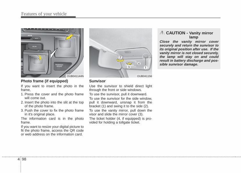
Features of your vehicle
984
Photo frame (if equipped)If you want to insert the photo in theframe,1. Press the cover and the photo frame
will come out.2. Insert the photo into the slit at the top
of the photo frame.3. Push the cover to fix the photo frame
in it's original place.The information card is in the photoframe.If you want to resize your digital picture tofit the photo frame, access the QR codeor web address on the information card.
SunvisorUse the sunvisor to shield direct lightthrough the front or side windows.To use the sunvisor, pull it downward.To use the sunvisor for the side window,pull it downward, unsnap it from thebracket (1) and swing it to the side (2).To use the vanity mirror, pull down thevisor and slide the mirror cover (3).The ticket holder (4, if equipped) is pro-vided for holding a tollgate ticket.
OUB041156
CAUTION - Vanity mirrorlamp
Close the vanity mirror coversecurely and return the sunvisor toits original position after use. If thevanity mirror is not closed securely,the lamp will stay on and couldresult in battery discharge and pos-sible sunvisor damage.
OUB041144N

4 99
Features of your vehicle
Power outlet (if equipped)The power outlet is designed to providepower for mobile telephones or otherdevices designed to operate with vehicleelectrical systems. The devices shoulddraw less than 10 amps with the enginerunning.Use the power outlet only when theengine is running and remove the acces-sory plug after use. Using the accessoryplug for prolonged periods of time withthe engine off could cause the battery todischarge.Only use 12V electric accessories whichare less than 10A in electric capacity.Adjust the air-conditioner or heater to thelowest operating level when using thepower outlet.
Close the cover when not in use.Some electronic devices can cause elec-tronic interference when plugged into avehicle’s power outlet. These devicesmay cause excessive audio static andmalfunctions in other electronic systemsor devices used in your vehicle.
Shopping bag holder • Do not hang a bag weighing more than
3 kg (7 lbs.). It may cause damage tothe shopping bag holder.
• Do not hang the frail objects when youdrive rough road, the objects may bedamaged.
Digital clock and calendar(if equipped)Whenever the battery terminals or relat-ed fuses are disconnected, you mustreset the clock and the calendar.When the ignition switch is in the ACC orON position, the clock buttons operate asfollows:
WARNING - Electric shockDo not put a finger or a foreign ele-ment (pin, etc.) into a power outletand do not touch with a wet hand.You may get an electric shock.
OUB041159OUB041157

Features of your vehicle
1004
Setup the clock and calenderWith audio off1. Press the [SETUP] or [Clock] button
(1) until the clock of the display blinks.2. Set the clock by turning the knob (2)
and press it.
With audio on1. Press the [SETUP] or [Clock] button
(1) until the clock adjust mode dis-played.
2. Set the clock by turning the knob(2)and press it.
Clothes hanger (if equipped)To use the hanger, pull down the upperportion of hanger.
OUB041161N
WARNINGDo not adjust the clock while driv-ing. You may lose your steeringcontrol and cause an accident thatresults in severe personal injury ordeath.
CAUTION - Hanging clothing
Do not hang heavy clothes, sincethose may damage the hook.
OUN026348

4 101
Features of your vehicle
Floor mat anchor(s)When using a floor mat on the front floorcarpet, make sure it attaches to the floormat anchor(s) in your vehicle. This keepsthe floor mat from sliding forward.
The following must be observed wheninstalling ANY floor mat to the vehicle.• Ensure that the floor mats are secure-
ly attached to the vehicle's floor matanchor(s) before driving the vehicle.
• Do not use ANY floor mat that cannotbe firmly attached to the vehicle's floormat anchors.
• Do not stack floor mats on top of oneanother (e.g. all-weather rubber mat ontop of a carpeted floor mat). Only a sin-gle floor mat should be installed ineach position.
IMPORTANT - Your vehicle was manu-factured with driver's side floor matanchors that are designed to securelyhold the floor mat in place. To avoid anyinterference with pedal operation, Kiarecommends that only the Kia floor matdesigned for use in your vehicle beinstalled.
Navigation system (if equipped)The navigation system ascertains thepresent position of your vehicle by usinginformation from satellites and guidesyou to the place you assign as the desti-nation.Detailed information for the navigationsystem is described in a separately sup-plied manual.
OEL049222
WARNING - After marketfloor mat
Do not install aftermarket floormats that are not capable of beingsecurely attached to the vehicle'sfloor mat anchors. Unsecured floormats can interfere with pedal oper-ation.
OUB041182N
For driver’s side For passenger’s side
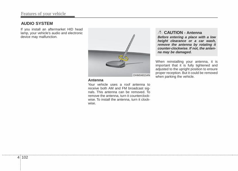
Features of your vehicle
1024
If you install an aftermarket HID headlamp, your vehicle’s audio and electronicdevice may malfunction.
AntennaYour vehicle uses a roof antenna toreceive both AM and FM broadcast sig-nals. This antenna can be removed. Toremove the antenna, turn it counterclock-wise. To install the antenna, turn it clock-wise.
When reinstalling your antenna, it isimportant that it is fully tightened andadjusted to the upright position to ensureproper reception. But it could be removedwhen parking the vehicle.
AUDIO SYSTEM
OHM048154N
CAUTION - AntennaBefore entering a place with a lowheight clearance or a car wash,remove the antenna by rotating itcounter-clockwise. If not, the anten-na may be damaged.

4 103
Features of your vehicle
Steering wheel audio control (if equipped) The steering wheel audio control buttonis installed to promote safe driving.Do not operate the audio remote controlbuttons simultaneously.
VOLUME (+/-) (1)• Push the lever up to increase volume.• Push the lever down to decrease vol-
ume.
MODE (3)Press the button to select Radio or CD(compact disc).
MUTE (4)• Press the MUTE button to cancel the
sound.• Press the MUTE button again to acti-
vate the sound.
SEEK/PRESET ( / ) (2)The SEEK/PRESET button has differentfunctions base on the system mode. Forthe following functions the button shouldbe pressed for 0.8 second or more.
RADIO modeIt will function as the AUTO SEEK selectbutton.
CDP/USB/iPod® modeIt will function as the FF/REW button.iPod® is a registered trademark of AppleInc.
If the SEEK button is pressed for lessthan 0.8 second, it will work as follows ineach mode.
RADIO modeIt will function as the PRESET STATIONselect buttons.
CDP/USB/iPod® modeIt will function as the TRACK UP/DOWNbutton.
Detailed information for audio controlbuttons is described in the followingpages in this section.
Bluetooth® Wireless Technology(if equipped)You can use a compatible phone viausing the Bluetooth® Wireless technolo-gy. Detailed information for theBluetooth® Wireless Technology isdescribed in the Audio system section.
OUB041163

Features of your vehicle
1044
Aux, USB and iPod®* (if equipped)If your vehicle has an aux and/or USB(universal serial bus) port or iPod port,you can use an aux port to connect audiodevices and an USB port to plug in anUSB and also an iPod port to plug in aniPod.When using a portable audio device con-nected to the power outlet, noise mayoccur during playback. If this happens,use the power source of the portableaudio device.
How vehicle audio worksAM and FM radio signals are broadcastfrom transmitter towers located aroundyour city. They are intercepted by theradio antenna on your vehicle.This signalis then received by the radio and sent toyour vehicle speakers.When a strong radio signal has reachedyour vehicle, the precise engineering ofyour audio system ensures the best pos-sible quality reproduction. However, insome cases the signal coming to yourvehicle may not be strong and clear. Thiscan be due to factors, such as the dis-tance from the radio station, closeness ofother strong radio stations or the pres-ence of buildings, bridges or other largeobstructions in the area.
AM broadcasts can be received atgreater distances than FM broadcasts.This is because AM radio waves aretransmitted at low frequencies. Theselong, low frequency radio waves can fol-low the curvature of the earth rather thantravelling straight out into the atmos-phere. In addition, they curve aroundobstructions so that they can provide bet-ter signal coverage.
JBM001
FM reception
OUB041165 JBM002
AM reception

4 105
Features of your vehicle
FM broadcasts are transmitted at highfrequencies and do not bend to follow theearth's surface. Because of this, FMbroadcasts generally begin to fade atshort distances from the station. Also,FM signals are easily affected by build-ings, mountains, or other obstructions.These can result in certain listening con-ditions which might lead you to believe aproblem exists with your radio. The fol-lowing conditions are normal and do notindicate radio trouble:
• Fading - As your vehicle moves awayfrom the radio station, the signal willweaken and sound will begin to fade.When this occurs, we suggest that youselect another stronger station.
• Flutter/Static - Weak FM signals orlarge obstructions between the trans-mitter and your radio can disturb thesignal causing static or fluttering nois-es to occur. Reducing the treble levelmay lessen this effect until the distur-bance clears.
• Station Swapping - As a FM signalweakens, another more powerful sig-nal near the same frequency maybegin to play. This is because yourradio is designed to lock onto the clear-est signal. If this occurs, select anotherstation with a stronger signal.
• Multi-Path Cancellation - Radio signalsbeing received from several directionscan cause distortion or fluttering. Thiscan be caused by a direct and reflect-ed signal from the same station, or bysignals from two stations with closefrequencies. If this occurs, selectanother station until the condition haspassed.
JBM004JBM003
FM radio station
JBM005

Features of your vehicle
1064
Satellite radio receptionYou may experience difficulties in receiv-ing SIRIUS satellite radio signals in thefollowing situations.
• If you are driving in a tunnel or a cov-ered parking area.
• If you are driving beneath the top levelof a multi-level freeway.
• If you drive under a bridge.• If you are driving next to a tall vehicle
(such as a truck or a bus) that blocksthe signal.
• If you are driving in a valley where thesurrounding hills or peaks block thesignal from the satellite.
• If you are driving on a mountain roadwhere is the signal blocked by moun-tains.
• If you are driving in an area with talltrees that block the signal (10m / 30 ft.or more), for example on an road thatgoes through a dense forest.
• The signal can become weak in someareas that are not covered by theSIRIUS repeater network.
There may be other unforeseen circum-stances leading to reception problemswith the SIRIUS satellite radio signal.
Using a cellular phone or a two-wayradio When a cellular phone is used inside thevehicle, noise may be produced from theaudio system. This does not mean thatsomething is wrong with the audio equip-ment. In such a case, use the cellularphone at a place as far as possible fromthe audio equipment.
SATELITE2SATELITE1
WARNING - Cell phoneuse
Do not use a cellular phone whiledriving. Stop at a safe location touse a cellular phone.
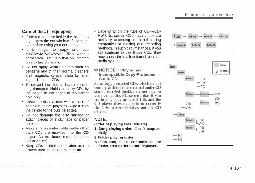
4 107
Features of your vehicle
Care of disc (if equipped)• If the temperature inside the car is too
high, open the car windows for ventila-tion before using your car audio.
• It is illegal to copy and useMP3/WMA/AAC/WAVE files withoutpermission. Use CDs that are createdonly by lawful means.
• Do not apply volatile agents such asbenzene and thinner, normal cleanersand magnetic sprays made for ana-logue disc onto CDs.
• To prevent the disc surface from get-ting damaged. Hold and carry CDs bythe edges or the edges of the centerhole only.
• Clean the disc surface with a piece ofsoft cloth before playback (wipe it fromthe center to the outside edge).
• Do not damage the disc surface orattach pieces of sticky tape or paperonto it.
• Make sure on undesirable matter otherthan CDs are inserted into the CDplayer (Do not insert more than oneCD at a time).
• Keep CDs in their cases after use toprotect them from scratches or dirt.
• Depending on the type of CD-R/CD-RW CDs, certain CDs may not operatenormally according to manufacturingcompanies or making and recordingmethods. In such circumstances, if youstill continue to use those CDs, theymay cause the malfunction of your caraudio system.
✽✽ NOTICE - Playing anIncompatible Copy-ProtectedAudio CD
Some copy protected CDs, which do notcomply with the international audio CDstandards (Red Book), may not play onyour car audio. Please note that if youtry to play copy protected CDs and theCD player does not perform correctlythe CDs maybe defective, not the CDplayer.
NOTE:Order of playing files (folders) :1. Song playing order : to sequen-
tially.2. Folder playing order :❋ If no song file is contained in the
folder, that folder is not displayed.

Features of your vehicle
1084
Type A Type B
❋No logo will be shown if the Bluetooth® wireless technology feature is not supported.

4 109
Features of your vehicle
SYSTEM CONTROLLERS ANDFUNCTIONS
Audio Head Unit
1. (EJECT)• Ejects the disc.
2.• Changes to FM/AM/SIRIUS mode.• Each time the key is pressed, the mode
is changed in order of FM1 ➟ FM2 ➟
AM ➟ SAT1 ➟ SAT2 ➟ SAT3❈ In Setup>Display, the radio pop up
screen will be displayed when [ModePop up] is turned .When the pop up screen is displayed,use the TUNE knob or keys ~
to select the desired mode.
3.• Changes to CD, USB, iPod, AUX, My
Music, BT Audio modes.• Each time the key is pressed, the mode
is changed in order of CD, USB, iPod,AUX, My Music, BT Audio modes.
❈ In Setup>Display, the media pop upscreen will be displayed when [ModePop up] is turned .When the pop up screen is displayed,use the TUNE knob or keys ~ to select the desired mode.
4.• Operates Phone Screen❈ When a phone is not connected, the
connection screen is displayed.
5.• Radio Mode : Automatically searches
for broadcast frequencies.• CD, USB, iPod, My Music modes :
- Shortly press the key (under 0.8 sec-onds): Moves to next or previoussong(file)
- Press and hold the key (over 0.8 sec-onds): Rewinds or fast-forwards thecurrent song(file)
6. PWR/VOL knob• Power Knob: Turns power On/Off by
pressing the knob• Volume Knob: Sets volume by turn-
ing the knob left/right
7. ~ (Preset)• Radio Mode: Saves frequencies (chan-
nels) or receives saved frequencies(channels)
• CD, USB, iPod, My Music mode- : Repeat- : Random
• In the Radio, Media, Setup, and Menupop up screen, the number menu isselected.
21
61
SEEKTRACK
PHONE
51
On
MEDIA
61
On
RADIO
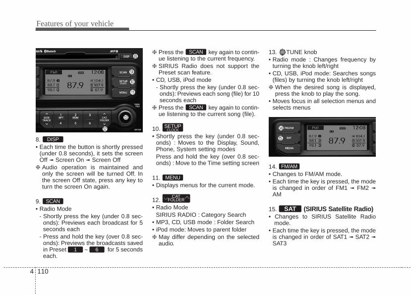
Features of your vehicle
1104
8.• Each time the button is shortly pressed
(under 0.8 seconds), it sets the screenOff ➟ Screen On ➟ Screen Off
❈ Audio operation is maintained andonly the screen will be turned Off. Inthe screen Off state, press any key toturn the screen On again.
9.• Radio Mode
- Shortly press the key (under 0.8 sec-onds): Previews each broadcast for 5seconds each
- Press and hold the key (over 0.8 sec-onds): Previews the broadcasts savedin Preset ~ for 5 secondseach.
❈ Press the key again to contin-ue listening to the current frequency.
❈ SIRIUS Radio does not support thePreset scan feature.
• CD, USB, iPod mode- Shortly press the key (under 0.8 sec-
onds): Previews each song (file) for 10seconds each
❈ Press the key again to contin-ue listening to the current song (file).
10.• Shortly press the key (under 0.8 sec-
onds) : Moves to the Display, Sound,Phone, System setting modes
Press and hold the key (over 0.8 sec-onds) : Move to the Time setting screen
11.• Displays menus for the current mode.
12.• Radio Mode
SIRIUS RADIO : Category Search• MP3, CD, USB mode : Folder Search• iPod mode: Moves to parent folder❈ May differ depending on the selected
audio.
13. TUNE knob• Radio mode : Changes frequency by
turning the knob left/right• CD, USB, iPod mode: Searches songs
(files) by turning the knob left/right❈ When the desired song is displayed,
press the knob to play the song.• Moves focus in all selection menus and
selects menus
14.• Changes to FM/AM mode.• Each time the key is pressed, the mode
is changed in order of FM1 ➟ FM2 ➟
AM
15. (SIRIUS Satellite Radio)• Changes to SIRIUS Satellite Radio
mode.• Each time the key is pressed, the mode
is changed in order of SAT1 ➟ SAT2 ➟SAT3
SAT
FM/AM
CATFOLDER
MENU
SETUPCLOCK
SCAN
SCAN
61
SCAN
DISP

4 111
Features of your vehicle
DISPLAY SETTINGS
Press the key Select [Display]through TUNE knob or keySelect menu through TUNE knob
Mode Pop up[Mode Pop up] Changes /selection mode• During On state, press the or
key to display the modechange pop up screen.
Text Scroll[Text Scroll] Set /• : Maintains scroll• : Scrolls only one (1) time.
Media DisplayWhen playing an MP3 file, select thedesired display info from ‘Folder/File’ or‘Album/Artist/Song’.
Off
On
OffOn
MEDIARADIO
OffOn
1SETUP

Features of your vehicle
1124
SOUND SETTINGS
Press the key Select [Sound]through TUNE knob or keySelect menu through TUNE knob
Sound SettingsThis menu allows you to set the ‘Bass,Middle, Treble’ and the Sound Fader andBalance.Select [Sound Settings] Selectmenu through TUNE knob Turn
TUNE knob left/right to set• Bass, Middle, Treble :Selects the sound tone.
• Fader, Balance : Moves the sound faderand balance.
• Default : Restores default settings.❈ Back : While adjusting values, re-
pressing the TUNE knob willrestore the parent menu.
Virtual SoundThe PoewrBass, PowerTreble, andSurround can be set.Select [Virtual Sound] Set menuthrough TUNE knob Set / through TUNE knob
• PowerBass : This is a sound systemfeature that provides live bass.
• PowerTreble : This is a sound systemfeature that provides live tremble.
• Surround : This is a sound system fea-ture that provides surround sound.
Speed Dependent Volume ControlThis feature is used to automatically con-trol the volume level according to thespeed of the vehicle.Select [SDVC] Set in 4 levels [Off/Low/Mid/High] of TUNE knob
Voice Recognition VolumeAdjusts voice recognition volume.Select [Voice Recognition Vol.] Setvolume of TUNE knob
Off
On
2SETUP

4 113
Features of your vehicle
CLOCK SETTINGS
Press the key Select [Clock]through TUNE knob or keySelect menu through TUNE knob
Clock SettingsThis menu is used to set the time.Select [Clock Settings] Set through
TUNE knob Press TUNE knob
❈ Adjust the number currently in focus toset the [hour] and press the tune knobto set the [minute].
Calendar SettingsThis menu is used to set the date(MM/DD/YYYY).
Select [Calendar Settings] Setthrough TUNE knob Press TUNE knob
❈ Adjust the number currently in focus tomake the settings and press the tuneknob to move to the next setting. (Setin order of Month/Day/Year)
Clock Display when Power is OFFSelect [Clock Disp.(Pwr Off) Set
/ through TUNE knob
• : Displays time/date on screen• : Turn off.Off
On
OffOn
3SETUP

Features of your vehicle
1144
PHONE SETUP
Press the key Select [Phone]through TUNE knob or keySelect menu through TUNE knob
Pair Phone
Select [Pair Phone] Set through TUNEknob
➀ Search for device names as displayedon your mobile phone and connect.
➁ Input the passkey displayed on thescreen. (Passkey : 0000)
❈ The device name and passkey will bedisplayed on the screen for up to 3minutes. If pairing is not completedwithin the 3 minutes, the mobile phonepairing process will automatically becanceled.
➂ Pairing completion is displayed.❈ In some mobile phones, pairing will
automatically be followed by connection.❈ It is possible to pair up to five
Bluetooth® wireless technologymobile phones.
4SETUP CAUTION
To pair a Bluetooth® wireless tech-nology mobile phone, authentica-tion and connection processes arefirst required. As a result, you can-not pair your mobile phone whiledriving the vehicle. First park yourvehicle before use.
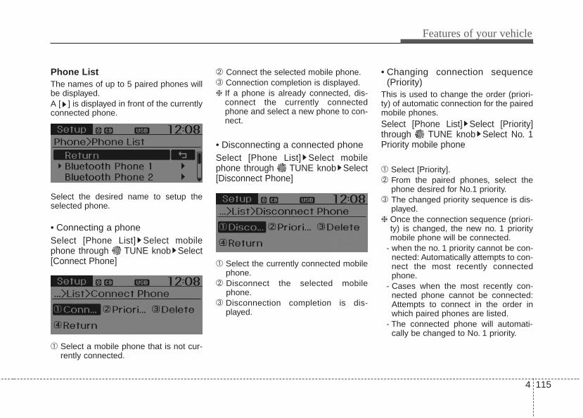
4 115
Features of your vehicle
Phone ListThe names of up to 5 paired phones willbe displayed.A [ ] is displayed in front of the currentlyconnected phone.
Select the desired name to setup theselected phone.
• Connecting a phoneSelect [Phone List] Select mobilephone through TUNE knob Select[Connect Phone]
➀ Select a mobile phone that is not cur-rently connected.
➁ Connect the selected mobile phone.➂ Connection completion is displayed.❈ If a phone is already connected, dis-
connect the currently connectedphone and select a new phone to con-nect.
• Disconnecting a connected phoneSelect [Phone List] Select mobilephone through TUNE knob Select[Disconnect Phone]
➀ Select the currently connected mobilephone.
➁ Disconnect the selected mobilephone.
➂ Disconnection completion is dis-played.
• Changing connection sequence(Priority)
This is used to change the order (priori-ty) of automatic connection for the pairedmobile phones.Select [Phone List] Select [Priority]through TUNE knob Select No. 1Priority mobile phone
➀ Select [Priority].➁ From the paired phones, select the
phone desired for No.1 priority.➂ The changed priority sequence is dis-
played.❈ Once the connection sequence (priori-
ty) is changed, the new no. 1 prioritymobile phone will be connected.
- when the no. 1 priority cannot be con-nected: Automatically attempts to con-nect the most recently connectedphone.
- Cases when the most recently con-nected phone cannot be connected:Attempts to connect in the order inwhich paired phones are listed.
- The connected phone will automati-cally be changed to No. 1 priority.

Features of your vehicle
1164
• DeleteSelect [Phone List] Select mobilephone through TUNE knob Select[Delete]
➀ Select the desired mobile phone.➁ Delete the selected mobile phone.➂ Deletion completion is displayed.❈ When attempting to delete a currently
connected phone, the phone is firstdisconnected.
Contacts DownloadThis feature is used to download con-tacts and call histories into the audio sys-tem.Select [Contacts Download] Selectthrough TUNE knob
Auto DownloadWhen connecting a mobile phone, it ispossible to automatically download newContacts and Call Histories.Select [Auto Download] Set /
through TUNE knob
Audio StreamingSongs (files) saved in your Bluetooth®
wireless technology mobile phone canbe played through the audio system.Select [Audio Streaming] Set /
through TUNE knob
Outgoing VolumeThis is used to set the volume of yourvoice as heard by the other party whileon a Bluetooth® wireless technologyhandsfree call.Select [Outgoing Volume] Set vol-ume through TUNE knob❈ Even while on a call, the volume can
be changed by using the key.
SEEKTRACK
Off
On
Off
On
CAUTION• The download feature may not be
supported in some mobilephones.
• If a different operation is per-formed while Contacts are beingdownloaded, downloading will bediscontinued. Contacts alreadydownloaded will be saved.
• When downloading new Contacts,delete all previously savedContacts before starting down-load.
CAUTIONThe Bluetooth® wireless technolo-gyaudio streaming feature may notbe supported in some mobilephones.
CAUTION• When you delete a mobile phone,
the mobile phone contacts willalso be erased.
• For stable Bluetooth® communi-cation, delete the mobile phonefrom the audio and also delete theaudio from your mobile phone.

4 117
Features of your vehicle
Bluetooth® wireless technologySystem OffThis feature is used when you do notwish to use the Bluetooth® wireless tech-nology system.Select [Bluetooth System Off] Setthrough TUNE knob
❈ If a phone is already connected, dis-connect the currently connected phoneand turn the Bluetooth® wireless tech-nology system off.
Using the Bluetooth® wirelesstechnology SystemTo use Bluetooth wireless technologywhen the system is currently off, followthese next steps.
• Turning On Bluetooth® wireless tech-nology through the Key
Press the key Screen Guidance❈ Moves to the screen where Bluetooth®
wireless technology functions can beused and displays guidance.
• Turning On Bluetooth® wireless tech-nology through the Key
Press the key Select [Phone]through TUNE knob or key➀ A screen asking whether to turn on
Bluetooth® wireless technology will bedisplayed.
➁ On the screen, select to turn onBluetooth® wireless technology anddisplay guidance.
❈ If the Bluetooth® wireless technologysystem is turned on, the system willautomatically try to connect the mostrecently connected Bluetooth® wire-less technology mobile phone.
YES
4SETUP
SETUP
PHONE
PHONE
CAUTIONBluetooth® wireless technologyconnection may become intermit-tently disconnected in some mobilephones. Follow these next steps totry again.1) Turn the Bluetooth® wireless
technology function within themobile phone ON/OFF and try toconnect again.
2) Turn the mobile phone powerON/OFF and try to connect again.
3) Completely remove the mobilephone battery, reboot, and thentry to connect again.
4) Reboot the audio system and tryto connect again
5) Delete all paired devices in yourmobile phone and the audio sys-tem and pair again for use.

Features of your vehicle
1184
SYSTEM SETTINGS
Press the key Select [System]through tune knob or key Selectmenu through TUNE knob
Memory InformationDisplays currently used memory andtotal system memory.Select [Memory Information] OKThe currently used memory is displayedon the left side while the total systemmemory is displayed on the right side.
Prompt FeedbackThis feature is used to change voicecommand feedback between Normal andExpert modes.Select [Prompt Feedback] Setthrough TUNE knob• Normal : This mode is for beginner
users and provides detailed instructionsduring voice command operation.
• Expert : This mode is for expert usersand omits some information duringvoice command operation. (When usingExpert mode, guidance instructions canbe heard through the [Help] or [Menu]commands.
LanguageThis menu is used to set the display andvoice recognition language.Select [Language] Set through TUNEknob
❈ The system will reboot after the lan-guage is changed.
❈ Language support by region
5SETUP

4 119
Features of your vehicle
RADIO : FM, AM OR SIRIUSChanging RADIO mode (FM, AMor SIRIUS)
Press the key to change themode in order of FM1➟FM2➟AM➟SAT1➟SAT2➟SAT3.• When the power is off, press the
key to turn on the audio systemand receive radio broadcasts.
• [Mode Pop up] On state : Displays thechange radio mode pop up screen.While the pop up screen is displayed,you can change the radio mode(FM1➟FM2➟AM➟SAT1➟SAT2➟SAT3) through the tune knob or ~
keys.
Adjust VolumeTurn the VOL knob left/right to adjustthe volume.
SEEKPress the key• Shortly pressing the key (under 0.8
seconds): Changes the frequency.• Pressing and holding the key (over 0.8
seconds): Automatically searches forthe next frequency.
Preset SEEKPress the key ~ • Shortly pressing the key (under 0.8
seconds): Plays the frequency saved inthe corresponding key.
• Pressing and holding the key (over 0.8seconds): Pressing and holding thedesired key from ~ willsave the currently playing broadcast tothe selected key and sound a BEEP.
SCANPress the key• Shortly pressing the key (under 0.8
seconds): The broadcast frequencyincreases and previews each broadcastfor 5 seconds each. After scanning allfrequencies, returns and plays the cur-rent broadcast frequency.
• Pressing and holding the key (over 0.8seconds): Previews the broadcastssaved in Preset ~ for 5 sec-onds each.
Selecting through manual searchTurn the TUNE knob left/right to adjustthe frequency.• FM : Changes by 200KHz• AM : Changes by 10MHz
61
SCANRADIO
61
61RADIO
SEEKTRACKRADIO
61
RADIO
RADIO

Features of your vehicle
1204
MENUWithin key are the A.Store (AutoStore).
A.StorePress the key Set [A.Store]through TUNE knob or key.Saves broadcasts with superior recep-tion to ~ keys. If no frequen-cies are received, then the most recentlyreceived frequency will be broadcast.
61
1MENU
MENU
4 121
Features of your vehicle
Satellite Radio channels:SIRIUS Satellite Radio has over 130 chan-nels, including 69 channels of 100% com-mercial-free music, plus sports, news, talkand entertainment available nationwide inyour vehicle. For more information and acomplete list of SIRIUS Satellite Radiochannels, visit sirius.com in the UnitedStates, sirius-canada.ca in Canada, or callSIRIUS at 1-888-539-7474.
Satellite Radio reception factors:To receive the satellite signal, your vehi-cle has been equipped with a satelliteradio antenna located on the roof of yourvehicle. The vehicle roof provides thebest location for an unobstructed, openview of the sky, a requirement of a satel-lite radio system. Like AM/FM, there areseveral factors that can affect satelliteradio reception performance:• Antenna obstructions: For optimal
reception performance, keep the anten-na clear of snow and ice build-up andkeep luggage and other material as faraway from the antenna as possible.
• Terrain: Hills, mountains, tall buildings,bridges, tunnels, freeway overpasses,parking garages, dense tree foliageand thunderstorms can interfere withyour reception.
SIRIUS Satellite Radio service:SIRIUS Satellite Radio is a subscription-based satellite radio service that broad-casts music, sports, news and entertain-ment programming to radio receivers,which are available for installation inmotor vehicles or factory installed, aswell as for the home, portable and wire-less devices, and through an Internetconnection on personal computer.Vehicles that are equipped with a factoryinstalled SIRIUS Satellite Radio systeminclude:• Hardware and an introductory trial sub-
scription term, which begins on thedate of sale or lease of the vehicle.
• For a small upgrade fee, access toSIRIUS music channels, and otherselect channels over the Internet usingany computer connected to theInternet (U.S. customers only).For information on extended subscrip-tion terms, contact SIRIUS at 1-888-539-7474.
NOTE:Satellite Radio requires SIRIUS® com-patible receiver and a subscription serv-ice fee after trial period.Vehicles without a factory-installedradio receiver require hardware pur-chase and installation. Please see yourdealer for further details. All fees andprogramming subject to change.Subscriptions governed by the SIRIUSTerms & Conditions available atwww.sirius.com / service terms.Available only in the 48 contiguousUnited States and the District ofColumbia. Service available in Canada;see www.siriuscanada.caKia shall not be responsible for anysuch programming changes.
Satellite Radio Electronic SerialNumber (ESN): This 12-digit SatelliteSerial Number is needed to re-activate,modify or track your satellite radioaccount. You will need this number whencommunicating with SIRIUS.
SIRIUS Satellite Radio information (if equipped)

Features of your vehicle
1224
SIRIUS RADIO
Using SIRIUS Satellite RadioYour Kia vehicle is equipped with a 3month complimentary period of SIRIUSSatellite Radio so you have access toover 130 channels of music, information,and entertainment programming.
ActivationIn order to extend or reactivate your sub-scription to SIRIUS Satellite Radio, youwill need to contact SIRIUS CustomerCare at 1-888-539-7474. Have your 12digit SID (Sirius Identification Number)/ESN(Electronic Serial Number) ready. To retrievethe SID/ESN, turn on the radio, press the[SAT] button, and tune to channel zero.
Please note that the vehicle will need tobe turned on, in Sirius mode, and havean unobstructed view of the sky in orderfor the radio to receive the activation sig-nal.
SEEKPress the key• Shortly pressing the key (under 0.8
seconds): select previous or next chan-nel.
• Pressing and holding the key (over 0.8seconds): continuously move to previ-ous or next channel.
❈ If the “Category” icon is displayed,channels are changed within the cur-rent category.
SCANPress the key• Shortly pressing the key (under 0.8
seconds): Previews each broadcast for5 seconds each
❈ Press the key again to contin-ue listening to the current frequency
❈ If the “Category” icon is displayed,channels are changed within the cur-rent category.
CategoryPress the key Set throughthe TUNE knob• The display will indicate the category
menus, highlight the category that thecurrent channel belongs to.
• In the Category List Mode, press thekey to navigate category list.
• Press the tune knob to select the lowestchannel in the highlighted category.
❈ If channel is selected by selecting cat-egory, then the “CATEGORY” icon isdisplayed at the top of the screen.
CATFOLDER
CATFOLDER
SCAN
SCANRADIORADIO

4 123
Features of your vehicle
PresetPress the key ~ • Shortly pressing the key (under 0.8
seconds): Plays the frequency saved inthe corresponding key.
• Pressing and holding the key (over 0.8seconds): Pressing and holding thedesired key from ~ willsave the current broadcast to theselected key and sound a BEEP.
✽✽ Troubleshooting1. Antenna Error
If this message is displayed, the anten-na or antenna cable is broken orunplugged. Please consult with yourKia dealership.
2. Acquiring SignalIf this message is displayed, it meansthat the antenna is covered and thatthe SIRIUS Satellite Radio signal isnot available. Ensure the antenna isuncovered and has a clear view of thesky.
Tune• Rotate TUNE knob : Changes the
channel number or scrolls category list.• Press TUNE knob : Selects the
menu.
MenuSelect category menu through the
TUNE knob Press the keySelect [ Info] through the TUNE
knob or key
Info (Information)Displays the Artist/Song info of the cur-rent song.
1
MENU
61
61RADIO

Features of your vehicle
1244
Care of disc• If the temperature inside the car is too
high, open the car windows to ventilatebefore using the system.
• It is illegal to copy and use MP3/WMAfiles without permission. Use CDs thatare created only by lawful means.
• Do not apply volatile agents, such asbenzene and thinner, normal cleanersand magnetic sprays made for ana-logue disc onto CDs.
• To prevent the disc surface from get-ting damaged, hold CDs by the edgesor the center hole only.
• Clean the disc surface with a piece ofsoft cloth before playback (wipe it fromthe center to the outside edge).
• Do not damage the disc surface orattach pieces of sticky tape or paper.
• Make certain only CDs are insertedinto the CD player (Do not insert morethan one CD at a time).
• Keep CDs in their cases after use toprotect them from scratches or dirt.
• Depending on the type of CD-R/CD-RWCDs, certain CDs may not operate nor-mally according to manufacturing compa-nies or making and recording methods. Insuch circumstances, continued use maycause malfunctions to your audio system.
✽✽ NOTICE - Playing anIncompatible CopyProtected Audio CD
Some copy protected CDs, which do notcomply with international audio CDstandards (Red Book), may not play onyour car audio. Please note that inabili-ties to properly play a copy protectedCD may indicate that the CD is defec-tive, not the CD player.
NOTE:Order of playing files (folders) :1. Song playing order : to sequen-
tially.2. Folder playing order :❋ If no song file is contained in the
folder, that folder is not displayed.
4 125
Features of your vehicle
CAUTION IN USING USB DEVICE
• To use an external USB device,make sure the device is not con-nected when starting up the vehi-cle. Connect the device afterstarting up.
• If you start the engine when theUSB device is connected, it maydamage the USB device. (USBflashdrives are very sensitive toelectric shock.)
• If the engine is started up orturned off while the external USBdevice is connected, the externalUSB device may not work.
• The System may not play inau-thentic MP3 or WMA files.1) It can only play MP3 files with
the compression rate between8Kbps~320Kbps.
2) It can only play WMA musicfiles with the compression ratebetween 8Kbps~320Kbps.
• Take precautions for static electrici-ty when connecting or disconnect-ing the external USB device.
(Continued)
(Continued)• An encrypted MP3 PLAYER is not
recognizable.• Depending on the condition of
the external USB device, the con-nected external USB device canbe unrecognizable.
• When the formatted byte/sectorsetting of External USB device isnot either 512BYTE or 2048BYTE,then the device will not be recog-nized.
• Use only a USB device formattedto FAT 12/16/32.
• USB devices without USB I/Fauthentication may not be recog-nizable.
• Make sure the USB connectionterminal does not come in contactwith the human body or otherobjects.
• If you repeatedly connect or dis-connect the USB device in a shortperiod of time, it may break thedevice.
• You may hear a strange noisewhen connecting or disconnect-ing a USB device.
(Continued)
(Continued)• If you disconnect the external USB
device during playback in USBmode, the external USB device canbe damaged or may malfunction.Therefore, disconnect the externalUSB device when the audio isturned off or in another mode. (e.g,Radio, SIRIUS or CD)
• Depending on the type and capacityof the external USB device or thetype of the files stored in the device,there is a difference in the timetaken for recognition of the device.
• Do not use the USB device for pur-poses other than playing music files.
• Playing videos through the USB isnot supported.
• Use of USB accessories such asrechargers or heaters using USBI/F may lower performance orcause trouble.
• If you use devices such as a USBhub purchased separately, thevehicle’s audio system may notrecognize the USB device. In thatcase, connect the USB devicedirectly to the multimedia termi-nal of the vehicle.
(Continued)

Features of your vehicle
1264
(Continued)• If the USB device is divided by
logical drives, only the music fileson the highest-priority drive arerecognized by car audio.
• Devices such as MP3 Player/Cellular phone/Digital camera canbe unrecognizable by standardUSB I/F can be unrecognizable.
• Charging through the USB maynot be supported in some mobiledevices.
• USB HDD or USB types liable toconnection failures due to vehiclevibrations are not supported.(i-stick type)
• Some non-standard USB devices(METAL COVER TYPE USB) canbe unrecognizable.
• Some USB flash memory readers(such as CF, SD, micro SD, etc.) orexternal-HDD type devices can beunrecognizable.
• Music files protected by DRM(DIGITAL RIGHTS MANAGEMENT)are not recognizable.
(Continued)
(Continued)• The data in the USB memory may
be lost while using this audio.Always back up important data ona personal storage device.
• Please avoid using USB memoryproducts which can be used askey chains or cellular phoneaccessories as they could causedamage to the USB jack. Pleasemake certain only to use plug typeconnector products as shownbelow.

4 127
Features of your vehicle
✽✽ NOTICE FOR USING THEiPod® DEVICE
• Some iPod models may not supportcommunication protocol and filesmay not properly play.Supported iPod models: - iPod Mini- iPod 4th(Photo) ~ 6th(Classic)generation- iPod Nano 1st~4th generation- iPod Touch 1st~2nd generation
• The order of search or playback ofsongs in the iPod can be differentfrom the order searched in theaudio system.
• If the iPod disabled due to its ownmalfunction, reset the iPod. (Reset:Refer to iPod manual)
• An iPod may not operate normallyon low battery.
• Some iPod devices, such as theiPhone, can be connected throughthe -interface. The device musthave audio Bluetooth® wirelesstechnology capability (such as forstereo headphone Bluetooth® wire-less technology ). The device canplay, but it will not be controlled bythe audio system.
(Continued)
(Continued)• To use iPod features within the audio,
use the cable provided upon purchas-ing an iPod device.
• Skipping or improper operation mayoccur depending on the characteris-tics of your iPod/Phone device.
• If your iPhone is connected to boththe Bluetooth® wireless technologyand USB, the sound may not be prop-erly played. In your iPhone, select theDock connector or Bluetooth® wire-less technology to change the soundoutput (source).
CAUTION IN USING THE iPod® DEVICE
• When connecting iPod with theiPod Power Cable, insert the con-nector to the multimedia socketcompletely. If not inserted com-pletely, communications betweeniPod and audio may be interrupted.
• When adjusting the sound effects ofthe iPod and the audio system, thesound effects of both devices willoverlap and might reduce or distortthe quality of the sound.
• Deactivate (turn off) the equalizerfunction of an iPod when adjust-ing the audio system’s volume,and turn off the equalizer of theaudio system when using theequalizer of an iPod.
• When not using iPod with caraudio, detach the iPod cable fromiPod. Otherwise, iPod may remainin accessory mode, and may notwork properly.

Features of your vehicle
1284
✽✽ NOTICE FOR USING THEMy Music
• Even if memory is available, a max-imum of 6,000 songs can be stored.
• The same song can be copied up to1,000 times.
• Memory info can be checked in theSystem menu of Setup.
✽✽ NOTICE FOR USING THEAUX
• Fully insert the AUX cable into theAUX terminal for use.

4 129
Features of your vehicle
BASIC METHOD OF USE :Audio CD / MP3 CD / USB /iPod / My Music
Press the key to change the modmode in order of CD➟USB(iPod)➟AUX➟My Music➟BT Audio.The folder/file name is displayed on thescreen.
❈ The CD is automatically played whena CD is inserted.
❈ The USB music is automaticallyplayed when a USB is connected.
Press the key Select [ Display]through the TUNE knob or keySelect [Media Display] Media Display• [Media Display] : The screen display
info can be changed to Album/Artist/Song name.
RepeatWhile song (file) is playing(RPT) keyAudio CD, MP3 CD, USB, iPod, My Musicmode: RPT on screen• To repeat one song (Shortly pressing
the key (under 0.8 seconds)): Repeatsthe current song.MP3 CD, USB mode: FLD.RPT onscreen
• To repeat folder (Pressing and holdingthe key (over 0.8 seconds)): repeats allfiles within the current folder.
❈ Press the key again to turn offrepeat.
RandomWhile song (file) is playing(RDM) keyAudio CD, My Music mode: RDM onscreen• Random (Shortly pressing the key
(under 0.8 seconds)): Plays all songs inrandom order.
MP3 CD, USB mode: FLD.RDM onscreen• Folder Random (Shortly pressing the
key (under 0.8 seconds)): Plays all fileswithin the current folder in randomorder.
iPod mode: ALB RDM on screen• Album Random (Shortly pressing the
key (under 0.8 seconds)): Plays all fileswithin albums of the current category inrandom order.
MP3 CD, USB, iPod mode: ALL RDM onscreen All Random (pressing and holding thekey (over 0.8 seconds)): Plays all files inrandom order.
❈ Press the key again to turn offrepeat.
2
2
1
1
1SETUP
MEDIA

Features of your vehicle
1304
Changing Song/FileWhile song (file) is playingkey• Shortly pressing the key (under 0.8
seconds): Plays the current song fromthe beginning.
❈ If the key is pressed againwithin 1 second, the previous song isplayed.
• Pressing and holding the key (over 0.8seconds): Rewinds the song.
While song (file) is playingkey• Shortly pressing the key (under 0.8
seconds): Plays the next song.• Pressing and holding the key (over 0.8
seconds): Fast forwards the song.
ScanWhile song (file) is playingkeyScans all songs for 10 seconds startingfrom the next song.❈ Press the key again to turn off.❈ The SCAN function is not supported in
iPod mode.
Folder Search : MP3 CD, USBModeWhile file is playing( ) (Folder Up) key• Searches the next folder.
While file is playing( )(Folder Down) key• Searches the previous folder.❈ If a folder is selected by pressing the
TUNE knob, the first file within theselected folder will be played.
❈ In iPod mode, moves to the ParentFolder.
Searching Songs (File)• Turning TUNE knob : Searches for
songs (files)• Pressing TUNE knob : Plays select-
ed song (file).
CATFOLDER
CATFOLDER
CATFOLDER
CATFOLDER
SCAN
SCAN
SEEKTRACK
SEEKTRACK
SEEKTRACK

4 131
Features of your vehicle
MENU : Audio CDPress the CD MP3 mode key toset the Repeat, Random, Informationfeatures.
RepeatPress the key Set [ RPT]through the TUNE knob or key to repeat the current song.❈ Press RPT again to turn off.
RandomPress the key Set [ RDM]through the TUNE knob or key to randomly play songs withinthe current folder.❈ Press RDM again to turn off.
InformationPress the key Set [ Info]through the TUNE knob or key to display information of the cur-rent song.❈ Press the key to turn off info
display.MENU
3MENU
2MENU
1MENU
MENU

Features of your vehicle
1324
MENU : MP3 CD / USBPress the CD MP3 mode key toset the Repeat, Folder Random, FolderRepeat, All Random, Information, andCopy features.
RepeatPress the key Set [ RPT]through the TUNE knob or key to repeat the current song.❈ Press RPT again to turn off.
Folder RandomPress the key Set [ F.RDM]through the TUNE knob or key to randomly play songs within thecurrent folder.❈ Press F.RDM again to turn off.
Folder RepeatPress the key Set [ F.RPT]through the TUNE knob or key to repeat songs within the cur-rent folder.❈ Press F.RPT again to turn off.
All RandomPress the key Set [ A.RDM]through the TUNE knob or keyto randomly play all songs within theCD.❈ Press A.RDM again to turn off.
InformationPress the key Set [ Info]through the TUNE knob or key to display information of the cur-rent song.❈ Press the key to turn off info
display.
CopyPress the key Set [ Copy]through the TUNE knob or key. This is used to copy the current songinto My Music. You can play the copiedMusic in My Music mode.
❈ If another key is pressed while copyingis in progress, a pop up asking youwhether to cancel copying is dis-played.
❈ If another media is connected orinserted (USB, CD, iPod, AUX) whilecopying is in progress, copying is can-celed.
❈ Music will not be played while copyingis in progress.
6MENU
MENU
5MENU
4MENU
3MENU
2MENU
1MENU
MENU

4 133
Features of your vehicle
MENU : iPodIn iPod mode, press the key toset the Repeat, Album Random, AllRandom, and Information features.
RepeatPress the key Set [ RPT]through the TUNE knob or key to repeat the current song.❈ Press RPT again to turn repeat off.
Album RandomPress the key Set [ Alb.RDM]through the TUNE knob or key.Plays albums within the currently playingcategory in random order.❈ Press Alb.RDM again to turn off.
All RandomPress the key Set [ A.RDM]through the TUNE knob or key.Plays all songs within the currently play-ing category in random order.❈ Press A.RDM again to turn off.
InformationPress the key Set [ Info]through the TUNE knob or key.Displays information of the current song.❈ Press the key to turn off info
display.MENU
4MENU
3MENU
2MENU
1MENU
MENU

Features of your vehicle
1344
MENU : My Music ModeIn My Music mode, press the keyto set the Repeat, Random, Information,Delete, Delete All, and Delete Selectionfeatures.
RepeatPress the key Set [ RPT]through the TUNE knob or key.Repeats the currently playing song.❈ Press RPT again to turn repeat off.
RandomPress the key Set [ RDM]through the TUNE knob or key.Plays all songs within the currently play-ing folder in random order.❈ Press RDM again to turn random off.
InformationPress the key Set [ Info]through the TUNE knob or key.Displays information of the current song.❈ Press the key to turn off info
display.
DeletePress the key Set [ Delete]through the TUNE knob or key.• Deletes currently playing fileIn the play screen, pressing delete willdelete the currently playing song.• Deletes file from list➀ Select the file you wish to delete by
using the TUNE knob.
➁ Press the key and select thedelete menu to delete the selected file.
Delete AllPress the key Set [ Del.All]through the TUNE knob or key.Deletes all songs of My Music.
Delete SelectionPress the key Set [ Del.Sel]through the TUNE knob or key.Songs within My Music are selected anddeleted.➀ Select the songs you wish to delete
from the list.
➁ After selecting, press the keyand select the delete menu.
MENU
6MENU
5MENU
MENU
4MENU
MENU
3MENU
2MENU
1MENU
MENU

4 135
Features of your vehicle
AUXAUX is used to play external MEDIA cur-rently connected with the AUX terminal.AUX mode will automatically start whenan external device is connected to theAUX terminal.If an external device is connected, youcan also press the key to changeto AUX mode.
❈ AUX mode cannot be started unlessthere is an external device connectedto the AUX terminal.
MEDIA

Features of your vehicle
1364
CAUTION IN USINGBLUETOOTH® WIRELESSTECHNOLOGY CELLU-LAR PHONE
• Do not use a cellular phone orperform Bluetooth® wireless tech-nology settings (e.g. pairing aphone) while driving.
• Some Bluetooth® wireless tech-nology-enabled phones may notbe recognized by the system orfully compatible with the system.
• Before using Bluetooth® wirelesstechnology related features of theaudio system, refer your phone’sUser’s Manual for phone-sideBluetooth® wireless technologyoperations.
• The phone must be paired to theaudio system to use Bluetooth®
wireless technology related fea-tures.
• You will not be able to use thehands-free feature when yourphone (in the car) is outside ofthe cellular service area (e.g. in atunnel, in a underground, in amountainous area, etc.).
(Continued)
(Continued)• If the cellular phone signal is poor
or the vehicles interior noise istoo loud, it may be difficult to hearthe other person’s voice during acall.
• Do not place the phone near orinside metallic objects, otherwise communications with Bluetooth®
wireless technology system orcellular service stations can bedisturbed.
• While a phone is connected throughBluetooth® wireless technologyyour phone may discharge quickerthan usual for additional Bluetooth®
wireless technology-related opera-tions.
• Some cellular phones or otherdevices may cause interferencenoise or malfunction to audiosystem. In this case, store thedevice in a different location mayresolve the condition.
• Phone contact names should besaved in English or they may notbe displayed correctly.
(Continued)
(Continued)• If Priority is set upon vehicle igni-
tion(IGN/ACC ON), the Bluetooth®
wireless technology phone willbe automatically connected.Even if you are outside, theBluetooth® wireless technology-phone will be automatically con-nected once you are in the vicini-ty of the vehicle.If you do not want automaticBluetooth® wireless technology-connection, turn the Bluetooth®
wireless technology feature off.• The hands-free call volume and
quality may differ depending onthe mobile phone type.

4 137
Features of your vehicle
NOTE:If you need more information aboutKia’s Bluetooth® wireless technol-ogy Contact kia website“www.kia.com” (OWNERS>GeneralInfo>BLUETOOTH).
What is Bluetooth®?Bluetooth® wireless technology thatallows multiple devices to be connectedin a short range, low-powered deviceslike hands-free, stereo headset, wirelessremote controller, etc. For more informa-tion, visit the Bluetooth® wireless tech-nology website at www.Bluetooth.com
CAUTION• Bluetooth® wireless technology
features can be used only whenthe mobile phone has been pairedand connected with the device.For more information on pairingand connecting Bluetooth® wire-less technology mobile phones,refer to the “Phone Setup” sec-tion.
• When a Bluetooth® wireless tech-nology mobile phone is connect-ed, a ( ) icon will appear at thetop of the screen. If a ( ) icon isnot displayed, this indicates thata Bluetooth® wireless technologydevice has not been connected.Your must connect the devicebefore use. For more informationon Bluetooth® wireless technolo-gy mobile phones, refer to the“Phone Setup” section.
(Continued)
(Continued)• Pairing and connecting a
Bluetooth® wireless technologymobile phone will work only whenthe Bluetooth® wireless technolo-gy option within your mobile phonehas been turned on. (Methods ofturning on the Bluetooth® wirelesstechnology feature may differdepending on the mobile phone.)
• In some mobile phones, startingthe ignition while talking throughBluetooth® wireless technologyhandsfree call will result in thecall becoming disconnected.(Switch the call back to yourmobile phone when starting theignition.)
• Some features may not be sup-ported in some Bluetooth® wire-less technology mobile phoneand devices.
• Bluetooth® wireless technologyoperation may be unstable depend-ing on the communication state.

Features of your vehicle
1384
Bluetooth® wireless technolo-gy Audio
Before using Bluetooth® wirelesstechnology audio features• Bluetooth® wireless technology
audio may not be supported dependingon the compatibility of your Bluetooth®
wireless technology mobile phone.• In order to use Bluetooth® wireless
technologyaudio, you must first pairand connect the Bluetooth® wirelesstechnology mobile phone.
• Bluetooth® wireless technologyaudio can be used only when the[Audio Streaming] of Phone is turned
.❈ Setting Bluetooth® wireless tech-
nology Audio Streaming : Press thekey Select [Phone] through
the tune knob or key Select[Audio Streaming] through the TUNE knob Set /
Starting Bluetooth® wirelesstechnology Audio• Press the key to change the
mode in order of CD➟USB➟AUX➟MyMusic➟BT Audio.
• If BT Audio is selected, Bluetooth®
wireless technology audio will startplaying.
❈ Audio may not automatically start play-ing in some mobile phones.
Using the Bluetooth® wirelesstechnology audio features• Play / StopPress the TUNE knob to play andpause the current song.❈ The previous song / next song / play /
pause functions may not be supportedin some mobile phones.
MEDIA
OffOn
4SETUP
On

4 139
Features of your vehicle
PHONE
Before using the Bluetooth® wirelesstechnology phone features
• In order to use Bluetooth® wirelesstechnology phone, you must first pairand connect the Bluetooth® wirelesstechnology mobile phone.
• If the mobile phone is not paired or con-nected, it is not possible to enter Phonemode. Once a phone is paired or con-nected, the guidance screen will be dis-played.
• If Priority is set upon vehicle ignition(IGN/ACC ON), the Bluetooth® wire-less technology phone will be auto-matically connected. Even if you areoutside, the Bluetooth® wirelesstechnology phone will be automatical-ly connected once you are in the vicini-ty of the vehicle. If you do not wantautomatic Bluetooth® wireless tech-nology phone connection, set theBluetooth® wireless technologypower to OFF.
Making a call using the steeringwheel remote controller(if equipped)
1. , button : Raises or lowersspeaker volume.
2. : Mode Change Each time thebutton pressed.
3. : Turns the sound on and off.4. button : Places and transfers calls.5. button : Ends calls or cancels func-
tions.6. button : Activates voice recognition.
• Check call history and making call➀ Shortly press (under 0.8 seconds) the
key on the steering remote con-troller .
➁ The call history list will be displayedon the screen.
➂ Press the key again to connect acall to the selected number.
• Redialing the most recently called num-ber
➀ Press and hold (over 0.8 seconds) thekey on the steering remote con-
troller.➁ The most recently called number is
redialed.❈ If call history does not exist, a screen
asking whether to download call histo-ry is displayed. (The download featuremay not be supported in some mobilephones)
MUTE
MODE
VOL _VOL +
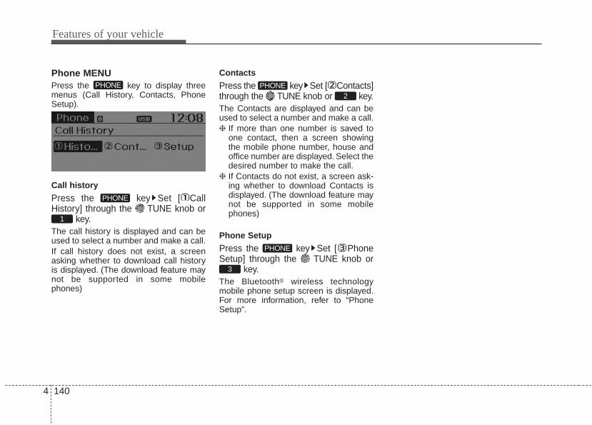
Features of your vehicle
1404
Phone MENUPress the key to display threemenus (Call History, Contacts, PhoneSetup).
Call history
Press the key Set [ CallHistory] through the TUNE knob or
key.The call history is displayed and can beused to select a number and make a call.If call history does not exist, a screenasking whether to download call historyis displayed. (The download feature maynot be supported in some mobilephones)
Contacts
Press the key Set [ Contacts]through the TUNE knob or key.The Contacts are displayed and can beused to select a number and make a call.❈ If more than one number is saved to
one contact, then a screen showingthe mobile phone number, house andoffice number are displayed. Select thedesired number to make the call.
❈ If Contacts do not exist, a screen ask-ing whether to download Contacts isdisplayed. (The download feature maynot be supported in some mobilephones)
Phone Setup
Press the key Set [ PhoneSetup] through the TUNE knob or
key.The Bluetooth® wireless technologymobile phone setup screen is displayed.For more information, refer to “PhoneSetup”.
3
PHONE
2PHONE
1
PHONE
PHONE

4 141
Features of your vehicle
VOICE COMMAND
Starting Voice Command• To start voice command, shortly press
the key on the steering wheelremote controller.
• If voice command is in [Normal Mode],then the system will say “Please say acommand. Beep”
❈ If voice command is in [Expert Mode],then the system will only say a “Beep-”
❈ Setting Voice command [NormalMode]/[Expert Mode]:Press the key Select [System]through the TUNE knob or key Select [Prompt Feedback] throughthe TUNE knob Set [NormalMode]/[Expert Mode]
• Say the voice command.
5SETUP
CAUTIONFor proper voice recognition, saythe voice command after the guid-ance message and the “Beep”sound.
(Continued)• After downloading Bluetooth®
wireless technology contacts, thesystem requires some times toconvert the contacts into voiceinformation. During this time,voice recognition may not oper-ate properly.
• Upon inputting your contacts,special symbols and numberscannot be recognized by voice.For example,“# John Doe%&” willbe recognized as “John Doe”.
CAUTION IN USINGVOICE COMMAND
• The voice recognition feature ofthis product supports recognitionof the commands listed withinthis user’s manual.
• While using voice recognition,operating the steering remotecontrol or the device will termi-nate voice recognition and allowyou to manually operate desiredfunctions.
• Position of the microphone isabove the head of the driver’sseat. For superior performance,maintain good posture when say-ing voice commands.
• Voice recognition may not func-tion properly due to outsidenoise. The following conditionscan affect the performance ofVoice Recognition:- When the windows and sunroof
are open- When the heating/cooling sys-
tem is on- When passing a tunnel- When driving on rugged and
uneven roads(Continued)
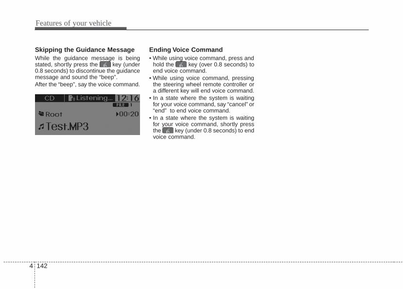
Features of your vehicle
1424
Skipping the Guidance MessageWhile the guidance message is beingstated, shortly press the key (under0.8 seconds) to discontinue the guidancemessage and sound the “beep”.After the “beep”, say the voice command.
Ending Voice Command• While using voice command, press and
hold the key (over 0.8 seconds) toend voice command.
• While using voice command, pressingthe steering wheel remote controller ora different key will end voice command.
• In a state where the system is waitingfor your voice command, say “cancel” or“end” to end voice command.
• In a state where the system is waitingfor your voice command, shortly pressthe key (under 0.8 seconds) to endvoice command.

4 143
Features of your vehicle
❈ Illustration on using voice commands
• Starting voice command.Shortly pressing the key (under 0.8 seconds):
• Skipping Voice RecognitionShortly pressing the key (under 0.8 seconds):
• End voice command.Shortly pressing the key (under 0.8 seconds):
while guidance message is being stated
Contacts
Cancel
More Help
More Help
Please say a command.
Please say a...
More Help.You can say Radio, FM, AM, SIRIUS, Media,CD, USB, Aux, My Music, iPod, Bluetooth Audio,Phone, Call History or Contacts.Please say a command.
More Help.You can say Radio, FM, AM, SIRIUS, Media,CD, USB, Aux, My Music, iPod, Bluetooth Audio,Phone, Call History or Contacts.Please say a command.
Contacts.Please say the name of the Contacts you wantto call.
Beep-
Beep-
Beep-
Beep Beep.. (end beep)
Shortly pressing the key(under 0.8 seconds)

Features of your vehicle
1444
Voice Command List• Common Commands:These are commands that can be used in all situations. (However, some commands may not be supported in special circumstances.)
Command FunctionMore Help Provides guidance on commands that can be
used anywhere in the system.
Help Provides guidance on commands that can beused within the current mode.
Call <Name> Calls <Name> saved in Contacts.
Dial <Number> Call can be made by dialing the spoken numbers.
Phone Provides guidance on Phone related commands.After saying this command, say “Call History”,“Contacts” to execute corresponding functions.
Call History Displays the Call History screen.
Contacts Displays the Contacts screen. After saying thiscommand, say the name of a contact saved inthe Contacts to automatically connect the call.
Dial Number Display the Dial number screen. After sayingthis command, you can say the number whatyou want to call.
Redial Connects the most recently called number.
Radio • When listening to the radio, displays the nextradio screen. (FM1➟FM2➟AM➟SAT1➟
SAT2➟SAT3➟FM1)
• When listening to a different mode, displaysthe most recently played radio screen.
FM • When currently listening to the FM radio,maintains the current state.
• When listening to a different mode, displaysthe most recently played FM screen.
Command FunctionFM1(FM One) Displays the FM1 screen.
FM2(FM Two) Displays the FM2 screen.
AM Displays the AM screen.
FM Preset 1~6 Plays the most recently played broadcastsaved in FM Preset 1~6.
AM Preset 1~6 Plays the broadcast saved in AM Preset 1~6.
FM 87.5~107.9 Plays the FM broadcast of the correspondingfrequency.
AM 530~1710 Plays the AM broadcast of the correspondingfrequency.
SIRIUS(Satellite) • When currently listening to the SIRIUS,maintains the current state.
• When listening to a different mode, displaysthe most recently played SIRIUS screen.
SIRIUS(Satellite) Displays the selected SIRIUS screen.
1~3
SIRIUS Channel Plays the selected SIRIUS channel.
Media Moves to the most recently played mediascreen.
Play Track 1~30 If a music CD has been inserted, plays thecorresponding track.
CD Plays the music saved in the CD.
(Call by Name)
0~223

4 145
Features of your vehicle
• FM/AM radio commands: Commands that can be used whilelistening to FM, AM radio.
Command FunctionSearch CD Moves to the CD track or file selection screen.
• For audio CDs, move to the screen and say thetrack number to play the corresponding track.
• Moves to the MP3 CD file selection screen.After manually operate the device to selectand play music.
USB Plays USB music.
Search USB Moves to the USB file selection screen. Aftermanually operate the device to select and playmusic.
iPod Plays iPod music.
Search iPod Moves to the iPod file selection screen. After,manually operate the device to select and playmusic.
My Music Plays the music saved in My Music.
Search My Music Moves to the My Music file selection screen.After manually operate the device to selectand play music.
AUX (Auxiliary) Plays the connected external device.
Bluetooth Audio Plays the music saved in connected Bluetooth®
device.
Mute Mutes the radio or music volume.
Pardon? Repeats the most recent comment.
Cancel (Exit) Ends voice command.
Command FunctionPreset 1~6 Plays the broadcast saved in Preset 1~6.
Auto Store Automatically selects radio broadcast fre-quencies with superior reception and saves inPresets 1~6.
Preset Save 1~6 Saves the current broadcast frequency toPreset 1~6.
Seek up Plays the next receivable broadcast.
Seek down Plays the previous receivable broadcast.
Next Preset Selects the preset number next to the mostrecently selected preset. (Example: When cur-rently listening to preset no. 3, then preset no.4 will be selected.)
Previous Preset Selects the preset number previous to themost recently selected preset. (Example:When currently listening to preset no. 3, thenpreset no. 2 will be selected.)
Scan Scans receivable frequencies from the currentbroadcast and plays for 5 seconds each.
Preset Scan Moves to the next preset from the currentpresent and plays for 10 seconds each.
Information Displays the information of the current broad-cast.(This feature can be used when receivingRBDS broadcasts.)

Features of your vehicle
1464
• Satellite radio commands: Commands that can be usedwhile listening to Satellite Radio.
• Audio CD commands: Commands that can be used whilelistening to Audio CD.
Command FunctionChannel Up Plays the channel next to the current broad-
cast.
Channel Down Plays the channel previous to the currentbroadcast.
Next Preset Selects the preset number next to the mostrecently selected preset. (Example: When cur-rently listening to preset no. 3, then preset no.4 will be selected.)
Previous Preset Selects the preset number previous to themost recently selected preset.(Example: When currently listening to presetno. 3, then preset no. 2 will be selected.)
Category Moves to the Category selection screen.
Scan Scans receivable channels from the currentbroadcast and plays for 5 seconds each.
Preset 1~6 Plays the broadcast saved in Preset 1~6.
Preset Save 1~6 Saves the current broadcast channel to 1~6.
Information Displays the information of the current broad-cast.
Command FunctionRandom Randomly plays the tracks within the CD.
Random Off Cancels random play to play tracks in sequen-tial order.
Repeat Repeats the current track.
Repeat Off Cancels repeat play to play tracks in sequen-tial order.
Next Track Plays the next track.
Previous Track Plays the previous track.
Scan Scans the tracks from the next track for 10seconds each.
Track 1~30 Plays the desired track number.
Search Track Moves to the track selection screen. After, saythe track name to play the corresponding track.
Information Displays the information screen of the currenttrack.

4 147
Features of your vehicle
• MP3 CD / USB commands: Commands that can be usedwhile listening to music files saved in CD and USB.
• iPod Commands: Commands that can be used while playingiPod.
Command FunctionRandom Randomly plays the files within the current
folder.
All Random Randomly plays all saved files.
Random Off Cancels random play to play files in sequentialorder.
Repeat Repeats the current file.
Folder Repeat Repeats all files in the current folder.
Repeat Off Cancels repeat play to play files in sequentialorder.
Next File Plays the next file.
Previous File Plays the previous file.
Scan Scans the files from the next files for 10 sec-onds each.
Search File Moves to the file selection screen.
Search Folder Moves to the folder selection screen.
Information Displays the information screen of the currentfile.
Copy Copies the current file into My Music.
Command FunctionAll Random Randomly plays all saved songs.
Album Random Randomly plays the songs within the currentcategory.
Random Off Cancels random play to play songs in sequen-tial order.
Repeat Repeats the current song.
Repeat Off Cancels repeat play to play songs in sequen-tial order.
Next Song Plays the next song.
Previous Song Plays the previous song.
Search Song Moves to the song selection screen.
Information Displays the information screen of the currentsong.

Features of your vehicle
1484
• My Music Commands: Commands that can be used whileplaying My Music.
• Bluetooth® wireless technology Audio Commands:Commands that can be used while playing Phone Music.
Command FunctionRandom Randomly plays all saved files.
Random Off Cancels random play to play files in sequentialorder.
Repeat Repeats the current file.
Repeat Off Cancels repeat play to play files in sequentialorder.
Next File Plays the next file.
Previous File Plays the previous file.
Scan Scans the files from the next files for 10 sec-onds each.
Search File Moves to the file selection screen.
Information Displays the information screen of the currentfile.
Delete Deletes the current file. You will bypass anadditional confirmation process.
Delete All Deletes all files saved in My Music. You willbypass an additional confirmation process.
Command FunctionPlay Plays the currently paused song.
Pause Pauses the current song.

5
Before driving / 5-3Key positions / 5-4ENGINE START/STOP button / 5-6Starting the engine / 5-9Manual transaxle / 5-12Automatic transaxle / 5-15Brake system / 5-21Cruise control system / 5-32ISG (Idle Stop and Go) system / 5-37Active eco system / 5-41Economical operation / 5-42
Special driving conditions / 5-44Winter driving / 5-48Trailer towing / 5-50Vehicle load limit / 5-51Vehicle weight / 5-56
Driving your vehicle

Driving your vehicle
25
Be sure the exhaust system doesnot leak.The exhaust system should be checkedwhenever the vehicle is raised to changethe oil or for any other purpose. If youhear a change in the sound of theexhaust or if you drive over somethingthat strikes the underneath side of thecar, have the exhaust system checked assoon as possible by an authorized Kiadealer.
WARNING - Engineexhaust
Do not inhale exhaust fumes orleave your engine running in aenclosed area for a prolonged time.Exhaust fumes contain carbonmonoxide, a colorless, odorlessgas that can cause unconscious-ness and death by asphyxiation.
WARNING - Open tailgateDo not drive with the tailgate open.Poisonous exhaust gases can enterthe passenger compartment If you must drive with the tailgateopen proceed as follows:1. Close all windows.2. Open side vents.3. Set the air intake control at
"Fresh", the air flow control at"Floor" or "Face" and the fan atthe highest speed.

5 3
Driving your vehicle
Before entering vehicle• Be sure that all windows, outside mir-
ror(s), and outside lights are clean.• Check the condition of the tires.• Check under the vehicle for any sign of
leaks.• Be sure there are no obstacles behind
you if you intend to back up.
Necessary inspections Fluid levels, such as engine oil, enginecoolant, brake fluid, and washer fluidshould be checked on a regular basis,with the exact interval depending on thefluid. Further details are provided inSection 7, “Maintenance”.
Before starting • Close and lock all doors.• Position the seat so that all controls are
easily reached.• Buckle your seat belt.• Adjust the inside and outside rearview
mirrors.• Be sure that all lights work.• Check all gauges.• Check the operation of warning lights
when the ignition switch is turned tothe ON position.
• Release the parking brake and makesure the brake warning light goes out.
For safe operation, be sure you are famil-iar with your vehicle and its equipment.
BEFORE DRIVING
WARNING - Distracteddriving
Focus on the road while driving.The driver's primary responsibilityis in the safe and legal operation ofthe vehicle. Use of any handleddevices, other equipment or vehiclesystems that distract the driveshould not be used during vehicleoperation.
WARNING - Check surrounding
Always check the surrounding areasnear your vehicle for people, espe-cially children, before putting a vehi-cle into D (Drive) or R (Reverse).

Driving your vehicle
45
Illuminated ignition switch (if equipped)Whenever a front door is opened, theignition switch will illuminate for your con-venience, provided the ignition switch isnot in the ON position.The light will go offimmediately when the ignition switch isturned on. It will also go off after about 30seconds when the door is closed.
KEY POSITIONS
WARNING - Fire riskWhen you intend to park or stop thevehicle with the engine on, be care-ful not to depress the acceleratorpedal for a long period of time. Itmay overheat the engine or exhaustsystem and cause fire.
WARNING - Driving whileintoxicated
Do not drive while intoxicated.Drinking and driving is dangerous.Even a small amount of alcohol willaffect your reflexes, perceptionsand judgment. Driving while underthe influence of drugs is as danger-ous as or more dangerous thandriving drunk.
WARNING - Loose objectSecurely store items in your vehi-cle. When you make a sudden stopor turn the steering wheel rapidly,loose objects may drop on the floorand it could interfere with the oper-ation of the foot pedals, possiblycausing an accident.
OUB051001

5 5
Driving your vehicle
Ignition switch positionLOCKThe ignition key can be removed only inthe LOCK position.When turning the ignition switch to theLOCK position, push the key inward atthe ACC position and turn the key towardthe LOCK position.Before leaving the driver’s seat, alwaysmake sure the shift lever is engaged in1st gear for the manual transaxle or P(Park) for automatic transaxle, set theparking brake fully and shut the engineoff.
ACC (Accessory)The electrical accessories are operative.
ONThe warning lights can be checked beforethe engine is started. This is the normalrunning position after the engine is started.Do not leave the ignition switch ON if theengine is not running to prevent batterydischarge.
STARTTurn the ignition switch to the START posi-tion to start the engine. The engine willcrank until you release the key; then itreturns to the ON position.The brake warn-ing light can be checked in this position.
OTD059016
WARNING - Ignition switchNever turn the ignition switch toLOCK or ACC while the vehicle ismoving.This would result in loss ofdirectional control and brakingfunction, which could cause anaccident.
WARNING - Steering wheelNever reach for any controlsthrough the steering wheel whilethe vehicle is in motion. The pres-ence of your hand or arm in thisarea could cause a loss of vehiclecontrol.

Driving your vehicle
65
Illuminated ENGINE START/STOPbuttonWhenever the front door is opened, theENGINE START/STOP button will illumi-nate for your convenience. The light willgo off after about 30 seconds when thedoor is closed.
ENGINE START/STOP buttonpositionOFF
To turn off the engine (START/RUN posi-tion) or vehicle power (ON position),press the ENGINE START/STOP buttonwith the shift lever in the P (Park) posi-tion. When you press the ENGINESTART/STOP button without the shiftlever in the P (Park) position, theENGINE START/STOP button will notchange to the OFF position but to theACC position.
In an emergency situation while the vehi-cle is in motion, you are able to turn theengine off and to the ACC position bypressing the ENGINE START/STOP but-ton for more than 2 seconds or 3 timessuccessively within 3 seconds. If thevehicle is still moving, you can restart theengine without depressing the brakepedal by pressing the ENGINESTART/STOP button with the shift leverin the N (Neutral) position.
ENGINE START/STOP BUTTON (IF EQUIPPED)
OUB051004
White

5 7
Driving your vehicle
ACC(Accessory)
Press the ENGINE START/STOP buttonwhile it is in the OFF position withoutdepressing the brake pedal.The electrical accessories are opera-tional.If the ENGINE START/STOP button is inthe ACC position for more than 1 hour,the button is turned off automatically toprevent battery discharge.
ON
Press the ENGINE START/STOP buttonwhile it is in the ACC position withoutdepressing the brake pedal.The warning lights can be checkedbefore the engine is started. Do not leavethe ENGINE START/STOP button in theON position for a long time. The batterymay discharge, because the engine isnot running.
START/RUN
To start the engine, depress the brakepedal and press the ENGINE START/STOP button with the shift lever in the P(Park) or the N (Normal) position. Foryour safety, start the engine with the shiftlever in the P (Park) position.If you press the ENGINE START/STOPbutton without depressing the brakepedal, the engine will not start and thebutton will change as follow:OFF ➔ ACC ➔ ON ➔ OFF
Orange Blue Not illuminated

Driving your vehicle
85
If you leave the ENGINE START/ STOPbutton in the ACC or ON position for along time, the battery will discharge.
WARNING - Starting vehicle
Never press the ENGINESTART/STOP button while the vehi-cle is in motion.This would result inloss of directional control and brak-ing function, which could cause anaccident.

5 9
Driving your vehicle
Starting the engine with an igni-tion key (if equipped)
1. Make sure the parking brake isapplied.
2. Manual Transaxle - Depress theclutch pedal fully and shift thetransaxle into Neutral. Keep the clutchpedal and brake pedal depressedwhile turning the ignition switch to thestart position.Automatic Transaxle - Place thetransaxle shift lever in P (Park).Depress the brake pedal fully.You can also start the engine whenthe shift lever is in the N (Neutral)position.
3. Turn the ignition switch to START andhold it there until the engine starts (amaximum of 10 seconds), thenrelease the key.
4. In extremely cold weather (below -18°C / 0°F) or after the vehicle hasnot been operated for several days, letthe engine warm up without depress-ing the accelerator.
Whether the engine is cold or warm, itshould be started without depressingthe accelerator.
If the engine stalls while the vehicle is inmotion, do not attempt to move the shiftlever to the P (Park) position. If traffic androad conditions permit, you may put theshift lever in the N (Neutral) positionwhile the vehicle is still moving and turnthe ignition switch to the START positionin an attempt to restart the engine.
STARTING THE ENGINE
WARNING - Properfootwear
Always wear appropriate shoeswhen operating your vehicle.Unsuitable shoes (high heels, skiboots, sandals, etc.) may interferewith your ability to use the brakeand accelerator pedal.
CAUTION - StarterDo not engage the starter for morethan 10 seconds. If the engine stallsor fails to start, wait 5 to 10 secondsbefore re-engaging the starter.Improper use of the starter maydamage it.

Driving your vehicle
105
Starting the engine with a smartkey (if equipped)1. Carry the smart key or leave it inside
the vehicle.2. Make sure the parking brake is firmly
applied3. Place the transaxle shift lever in P
(Park).4. Press the ENGINE START/STOP but-
ton while depressing the brake pedal.5. In extremely cold weather (below -
18°C / 0°F) or after the vehicle has notbeen operated for several days, let theengine warm up without depressingthe accelerator.
Whether the engine is cold or warm, itshould be started without depressing theaccelerator.• Even if the smart key is in the vehicle,
if it is far away from you, the enginemay not start.
• When the ENGINE START/STOP but-ton is in the ACC position or above, ifany door is opened, the system checksfor the smart key. If the smart key is notin the vehicle,the “ ” or “ ” indi-cator will blink or the warning "Key notin vehicle" will illuminate on the LCDdisplay. And if all doors are closed, thechime will sound for 5 seconds. Theindicator or warning will turn off whilethe vehicle is moving. Always have thesmart key with you.
The engine will start, only when thesmart key is in the vehicle.
KEYOUT
WARNING - Unintendedvehicle movement
Never leave the smart key in thevehicle with children or vehicleoccupants who are unfamiliar withthe vehicle operation. Pushing theENGINE START/STOP button whilethe smart key is in the vehicle mayresult in unintended engine activa-tion and/or unintended vehiclemovement.
OUB051004

5 11
Driving your vehicle
✽✽ NOTICE• If the battery is weak or the smart key
does not work correctly, you can startthe engine by pressing the enginestart/stop button with the smart key.
(Continued)
(Continued)• When the stop lamp fuse is blown, you
can't start the engine normally.Replace the fuse with a new one. If itis not possible, you can start theengine by pressing the ENGINESTART/STOP button for 10 secondswhile it is in the ACC position. Theengine can start without depressingthe brake pedal. But for your safetyalways depress the brake pedal beforestarting the engine.
Do not press the ENGINE START/ STOPbutton for more than 10 seconds exceptwhen the stop lamp fuse is blown.
OUB051003

Driving your vehicle
125
Manual transaxle operationThe manual transaxle has 6 forwardgears.This shift pattern is imprinted on the shiftknob. The transaxle is fully synchronizedin all forward gears so shifting to either ahigher or a lower gear is easily accom-plished.Depress the clutch pedal down fully whileshifting, then release it slowly.If your vehicle is equipped with an igni-tion lock switch, the engine will not startwhen starting the engine withoutdepressing the clutch pedal.The shift lever must be returned to theneutral position before shifting into R(Reverse). The ring (1) located below theshift knob must be pulled upward whilemoving the shift lever to the R (Reverse)position.Make sure the vehicle is completelystopped before shifting into R (Reverse).Never operate the engine with thetachometer (rpm) in the red zone.
MANUAL TRANSAXLE (IF EQUIPPED)
CAUTION - DownshiftingDo not downshift more than 2 gearsor downshift the gear when theengine is running at high speed(5,000 RPM or higher). Such adownshifting may damage theengine.
OUB051013
The shift lever can be moved without-pressing the button.
The button (1) should be pressed whenmoving the shift lever into reverse.

5 13
Driving your vehicle
• During cold weather, shifting may bedifficult until the transaxle lubricant iswarmed up. This is normal and notharmful to the transaxle.
• If you've come to a complete stop andit's hard to shift into 1st or R (Reverse),leave the shift lever at neutral positionand release the clutch. Depress theclutch pedal back down, and then shiftinto 1st or R (Reverse) gear position.
Using the clutchThe clutch should be depressed all theway to the floor before shifting, thenreleased slowly. The clutch pedal shouldalways be fully released while driving. Donot rest your foot on the clutch pedalwhile driving. This can cause unneces-sary wear. Do not partially engage theclutch to hold the vehicle on an incline.This causes unnecessary wear. Use thefoot brake or parking brake to hold thevehicle on an incline. Do not operate theclutch pedal rapidly and repeatedly.
DownshiftingWhen you must slow down in heavy traf-fic or while driving up steep hills, down-shift before the engine starts to labor.Downshifting reduces the chance ofstalling and gives better accelerationwhen you need to increase your speedagain. When the vehicle is traveling downsteep hills, downshifting helps maintainsafe speed and prolongs brake life.
CAUTION - Premature wear• Do not drive with your foot rest-
ing on the clutch pedal or use theclutch pedal to hold the vehiclestopped on an uphill or at a trafficlight. This will result in prematureclutch wear.
• Do not use the shift lever as ahandrest during driving, as thiscan result in premature wear ofthe transaxle shift forks.
WARNING - Incline parkingBefore leaving the driver’s seat,always set the parking brake fullyand shut the engine off. Then makesure the transaxle is shifted into 1stgear when the vehicle is parked ona level or uphill grade, and shiftedinto R (Reverse) on a downhillgrade. Unexpected and suddenvehicle movement can occur ifthese precautions are not followedin the order identified.

Driving your vehicle
145
Good driving practices• Never take the vehicle out of gear and
coast down a hill. This is extremelyhazardous. Always leave the vehicle ingear.
• Don't "ride" the brakes. This can causethem to overheat and malfunction.Instead, when you are driving down along hill, shift to a lower gear. Whenyou do this, engine braking will helpslow down the vehicle.
• Slow down before shifting to a lowergear. This will help avoid over-revvingthe engine, which can cause damage.
• Slow down when you encounter crosswinds. This gives you much better con-trol of your vehicle.
• Be sure the vehicle is completelystopped before you attempt to shift intoR (Reverse). The transaxle can bedamaged if you do not.
• Exercise extreme caution when drivingon a slippery surface. Be especiallycareful when braking, accelerating orshifting gears. On a slippery surface,an abrupt change in vehicle speed cancause the drive wheels to lose tractionand the vehicle to go out of control.
• Always buckle-up! In a collision, anunbelted occupant is significantly morelikely to be seriously injured or killedthan a properly belted occupant.
• Never exceed posted speed limits.
WARNING - Vehicle handling
Avoid high speeds when corneringor turning. High speed corneringand turning increases the risk ofvehicle rollover due to loss of vehi-cle control. Rollover accidents areextremely violent and unpre-dictable.
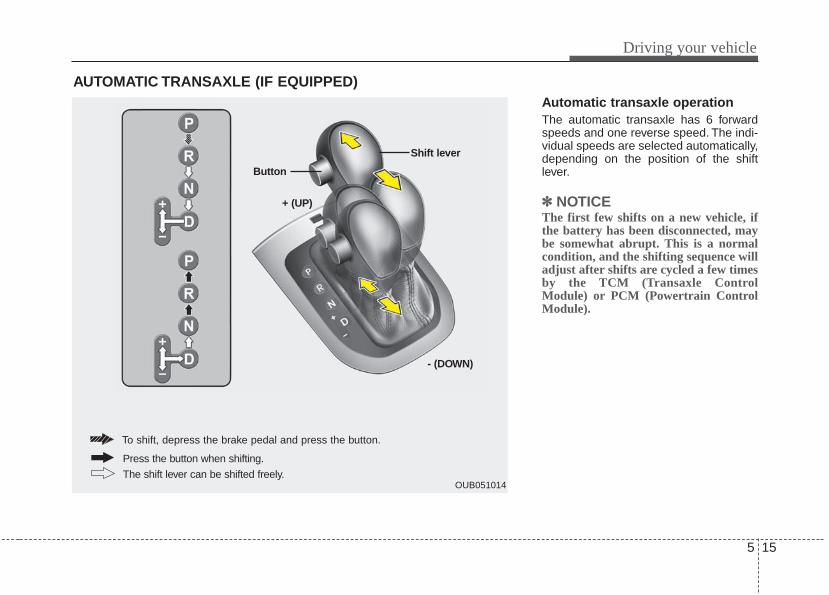
5 15
Driving your vehicle
Automatic transaxle operationThe automatic transaxle has 6 forwardspeeds and one reverse speed. The indi-vidual speeds are selected automatically,depending on the position of the shiftlever.
✽✽ NOTICEThe first few shifts on a new vehicle, ifthe battery has been disconnected, maybe somewhat abrupt. This is a normalcondition, and the shifting sequence willadjust after shifts are cycled a few timesby the TCM (Transaxle ControlModule) or PCM (Powertrain ControlModule).
AUTOMATIC TRANSAXLE (IF EQUIPPED)
OUB051014
+ (UP)
Button
Shift lever
- (DOWN)
To shift, depress the brake pedal and press the button.
The shift lever can be shifted freely.
Press the button when shifting.

Driving your vehicle
165
For smooth operation, depress the brakepedal when shifting from N (Neutral) to aforward or reverse gear.
When stopped on an upgrade, do nothold the vehicle with engine power. Usethe service brake or the parking brake.
Transaxle rangesThe indicator light in the instrument clus-ter displays the shift lever position whenthe ignition switch is in the ON position.
P (Park)Always come to a complete stop beforeshifting into P (Park). This position locksthe transaxle and prevents the frontwheels from rotating.
Shifting into P (Park) while the vehicle isin motion will cause the drive wheels tolock which will cause you to lose controlof the vehicle.
WARNING - Automatictransaxle
Before leaving the driver’s seat,always make sure the shift lever isin the P (Park) position; then set theparking brake fully and shut theengine off. Do not use the P posi-tion in place of the parking brake.Always make sure the shift lever islatched in the P position and set theparking brake fully. Unexpectedand sudden vehicle movement canoccur if these precautions are notfollowed.
CAUTION - TransaxleTo avoid damage to your transaxle,do not accelerate the engine in R(Reverse) or any forward gear posi-tion with the brakes on. Thetransaxle may be damaged if youshift into P (Park) while the vehicleis in motion.

5 17
Driving your vehicle
R (Reverse)Use this position to drive the vehiclebackward.
N (Neutral)The wheels and transaxle are notengaged. The vehicle will roll freely evenon the slightest incline unless the parkingbrake or service brakes are applied.
D (Drive)This is the normal forward driving posi-tion. The transaxle will automatically shiftthrough a 6-gear sequence, providing thebest fuel economy and power.
For extra power when passing anothervehicle or climbing grades, depress theaccelerator fully, at which time thetransaxle will automatically downshift tothe next lower gear.
Sports modeWhether the vehicle is stopped or inmotion, sports mode is selected by push-ing the shift lever from the D (Drive) posi-tion into the manual gate. To return to D(Drive) range operation, push the shiftlever back into the main gate.
In sports mode, moving the shift leverbackwards and forwards will allow you tomake gearshifts rapidly. In contrast to amanual transaxle, the sports modeallows gearshifts with the acceleratorpedal depressed.
CAUTION - ShiftingAlways come to a complete stopbefore shifting into or out of R(Reverse); you may damage thetransaxle if you shift into R(Reverse) while the vehicle is inmotion, except when “Rocking theVehicle” explained in this section. OUB051060
+ (UP)
- (DOWN)Sportsmode

Driving your vehicle
185
Up (+) : Push the lever forward once toshift up one gear.
Down (-) : Pull the lever backwards onceto shift down one gear.
• In sports mode, the driver must exe-cute upshifts in accordance with roadconditions, taking care to keep theengine speed below the red zone.
• In sports mode, only the 6 forwardgears can be selected. To reverse orpark the vehicle, move the shift lever tothe R (Reverse) or P (Park) position asrequired.
• In sports mode, downshifts are madeautomatically when the vehicle slowsdown. When the vehicle stops, 1st gearis automatically selected.
• In sports mode, when the engine rpmapproaches the red zone shift pointsare varied to upshift automatically.
• To maintain the required levels of vehi-cle performance and safety, the systemmay not execute certain gearshiftswhen the shift lever is operated.
• When driving on a slippery road, pushthe shift lever forward into the +(up)position. This causes the transaxle toshift into the 2nd gear which is betterfor smooth driving on a slippery road.Push the shift lever to the -(down) sideto shift back to the 1st gear.
Shift lock system (if equipped)For your safety, the automatic transaxlehas a shift lock system which preventsshifting the transaxle out of P (Park)unless the brake pedal is depressed.To shift the transaxle from P (Park) into R(Reverse):1. Depress and hold the brake pedal.2. Start the engine or turn the ignition
switch to the ON position.3. Move the shift lever.If the brake pedal is repeatedlydepressed and released with the shiftlever in the P (Park) position, a chatteringnoise near the shift lever may be heard.This is a normal condition.
WARNING - Shifting frompark
Always fully depress the brakepedal before and while shifting outof the P (Park) position into anoth-er position to avoid inadvertentmotion of the vehicle.

5 19
Driving your vehicle
Shift-lock overrideIf the shift lever cannot be moved fromthe P (Park) or N (Neutral) position intothe R (Reverse) position with the brakepedal depressed, continue depressingthe brake, then do the following:
Shift-lock override (with smart key systme)1.Carefully remove the cap covering the
shift-lock access hole (1).2. Insert a key (or screwdriver) into the
access hole and press down on thekey (or screwdriver).
3.Move the shift lever.4.Have your vehicle inspected by an
authorized Kia dealer immediately
Ignition key interlock system (if equipped)The ignition key cannot be removedunless the shift lever is in the P (Park)position.
Good driving practices• Never move the shift lever from P
(Park) or N (Neutral) to any other posi-tion with the accelerator pedaldepressed.
• Never move the shift lever into P (Park)when the vehicle is in motion.
• Slow down before shifting to a lowergear. Otherwise, the lower gear maynot be engaged.
• Always use the parking brake. Do notdepend on placing the transaxle in P(Park) to keep the vehicle from moving.
• Optimum vehicle performance andeconomy is obtained by smoothlydepressing and releasing the accelera-tor pedal.
OUB051015N

Driving your vehicle
205
Moving up a steep grade from astanding startTo move up a steep grade from a stand-ing start, depress the brake pedal, shiftthe shift lever to D (Drive). Select theappropriate gear depending on loadweight and steepness of the grade, andrelease the parking brake. Depress theaccelerator gradually while releasing theservice brakes.
5 21
Driving your vehicle
Power brakes Your vehicle has power-assisted brakesthat adjust automatically through normalusage.In the event that the power-assistedbrakes lose power because of a stalledengine or some other reason, you canstill stop your vehicle by applying greaterforce to the brake pedal than you nor-mally would. The stopping distance, how-ever, will be longer.When the engine is not running, thereserve brake power is partially depletedeach time the brake pedal is applied. Donot pump the brake pedal when thepower assist has been interrupted.Pump the brake pedal only when neces-sary to maintain steering control on slip-pery surfaces.
Wet brakes may impair the vehicle’s abil-ity to safely slow down; the vehicle mayalso pull to one side when the brakes areapplied. Applying the brakes lightly willindicate whether they have been affectedin this way. To dry the brakes, apply themlightly while maintaining a safe forwardspeed until brake performance returns tonormal.
In the event of brake failure If service brakes fail to operate while thevehicle is in motion, you can make anemergency stop with the parking brake.The stopping distance, however, will bemuch greater than normal.
BRAKE SYSTEM
WARNING - Parking brakeAvoid applying the parking brake tostop the vehicle while it is movingexcept in an emergency situation.Applying the parking brake whilethe vehicle is moving at normalspeeds can cause a sudden loss ofcontrol of the vehicle. If you mustuse the parking brake to stop thevehicle, use great caution in apply-ing the brake.
WARNING - Steep hillbraking
Avoid continuous application of thebrakes when descending a long orsteep hill by shifting to a lowergear. Continuous brake applicationwill cause the brakes to overheatand could result in a temporaryloss of braking performance.
CAUTION - Brake pedalDo not drive with your foot restingon the brake pedal. This will createabnormally high brake tempera-tures which can cause excessivebrake lining and pad wear.
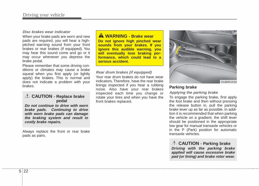
Driving your vehicle
225
Disc brakes wear indicator When your brake pads are worn and newpads are required, you will hear a high-pitched warning sound from your frontbrakes or rear brakes (if equipped). Youmay hear this sound come and go or itmay occur whenever you depress thebrake pedal.Please remember that some driving con-ditions or climates may cause a brakesqueal when you first apply (or lightlyapply) the brakes. This is normal anddoes not indicate a problem with yourbrakes.
Always replace the front or rear brakepads as pairs.
Rear drum brakes (if equipped)Your rear drum brakes do not have wearindicators. Therefore, have the rear brakelinings inspected if you hear a rubbingnoise. Also have your rear brakesinspected each time you change orrotate your tires and when you have thefront brakes replaced.
Parking brake Applying the parking brakeTo engage the parking brake, first applythe foot brake and then without pressingthe release button in, pull the parkingbrake lever up as far as possible. In addi-tion it is recommended that when parkingthe vehicle on a gradient, the shift levershould be positioned in the appropriatelow gear for manual transaxle vehicles orin the P (Park) position for automatictransaxle vehicles.
WARNING - Brake wearDo not ignore high pinched wearsounds from your brakes. If youignore this audible warning, youwill eventually lose braking per-formance, which could lead to aserious accident.
CAUTION - Parking brakeDriving with the parking brakeapplied will cause excessive brakepad (or lining) and brake rotor wear.
CAUTION - Replace brakepedal
Do not continue to drive with wornbrake pads. Continuing to drivewith worn brake pads can damagethe braking system and result incostly brake repairs.
OUB051016

5 23
Driving your vehicle
Releasing the parking brakeTo release the parking brake, first applythe foot brake and pull up the parkingbrake lever slightly. Secondly, press therelease button (1) and lower the parkingbrake lever (2) while holding the button.
Check the brake warning light by turningthe ignition switch ON (do not start theengine).This light will illuminate when theparking brake is applied with the ignitionswitch in the START or ON position.Before driving, be sure the parking brakeis fully released and the brake warninglight is off.If the brake warning light remains onafter the parking brake is released whilethe engine is running, there may be amalfunction in the brake system.Immediate attention is necessary.If at all possible, stop driving the vehicleimmediately. If that is not possible, useextreme caution while operating the vehi-cle and only continue to drive the vehicleuntil you can reach a safe location orrepair shop.
WARNING - Parking brakeuse
All vehicles should always have theparking brake fully engaged whenparking to avoid inadvertent move-ment of the vehicle which caninjure occupants or pedestrians.
W-75OUB051017

Driving your vehicle
245
Anti-lock brake system (ABS) (if equipped)ABS (or ESC) will not prevent accidentsdue to improper or dangerous drivingmaneuvers. Even though vehicle controlis improved during emergency braking,always maintain a safe distance betweenyou and objects ahead. Vehicle speedsshould always be reduced duringextreme road conditions.The vehicle should be driven at reducedspeeds in the following circumstances:• When driving on rough, gravel or
snow-covered roads• When driving on roads where the road
surface is pitted or has different sur-face heights.
Driving in these conditions increases thestopping distance for your vehicle.
The ABS continuously senses the speedof the wheels. If the wheels are going tolock, the ABS system repeatedly modu-lates the hydraulic brake pressure to thewheels.When you apply your brakes under con-ditions which may lock the wheels, youmay hear a “tik-tik’’ sound from thebrakes, or feel a corresponding sensationin the brake pedal. This is normal and itmeans your ABS is active.In order to obtain the maximum benefitfrom your ABS in an emergency situa-tion, do not attempt to modulate yourbrake pressure and do not try to pumpyour brakes. Press your brake pedal ashard as possible or as hard as the situa-tion allows the ABS to control the forcebeing delivered to the brakes.
✽✽ NOTICEA click sound may be heard in theengine compartment when the vehiclebegins to move after the engine is start-ed. These conditions are normal andindicate that the anti-lock brake systemis functioning properly.
• Even with the anti-lock brake system,your vehicle still requires sufficientstopping distance. Always maintain asafe distance from the vehicle in frontof you.
• Always slow down when cornering.The anti-lock brake system cannot pre-vent accidents resulting from exces-sive speeds.
• On loose or uneven road surfaces,operation of the anti-lock brake systemmay result in a longer stopping dis-tance than for vehicles equipped with aconventional brake system.
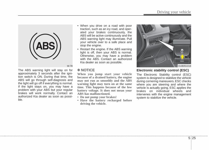
5 25
Driving your vehicle
The ABS warning light will stay on forapproximately 3 seconds after the igni-tion switch is ON. During that time, theABS will go through self-diagnosis andthe light will go off if everything is normal.If the light stays on, you may have aproblem with your ABS but your regularbrakes will work normally. Contact anauthorized Kia dealer as soon as possi-ble.
• When you drive on a road with poortraction, such as an icy road, and oper-ated your brakes continuously, theABS will be active continuously and theABS warning light may illuminate. Pullyour vehicle over to a safe place andstop the engine.
• Restart the engine. If the ABS warninglight is off, then your ABS is normal.Otherwise, you may have a problemwith the ABS. Contact an authorizedKia dealer as soon as possible.
✽✽ NOTICEWhen you jump start your vehiclebecause of a drained battery, the enginemay not run as smoothly and the ABSwarning light may turn on at the sametime. This happens because of the lowbattery voltage. It does not mean yourABS has malfunctioned.• Do not pump your brakes!• Have the battery recharged before
driving the vehicle.
Electronic stability control (ESC)The Electronic Stability control (ESC)system is designed to stabilize the vehicleduring cornering maneuvers. ESC checkswhere you are steering and where thevehicle is actually going. ESC applies thebrakes on individual wheels andintervenes with the engine managementsystem to stabilize the vehicle.
W-78 OUB051018
Driving your vehicle
265
Electronic stability control (ESC) will notprevent accidents. Excessive speed inturns, abrupt maneuvers and hydroplan-ing on wet surfaces can still result in seri-ous accidents. Only a safe and attentivedriver can prevent accidents by avoidingmaneuvers that cause the vehicle to losetraction. Even with ESC installed, alwaysfollow all the normal precautions for driv-ing - including driving at safe speeds forthe conditions.The Electronic Stability Control (ESC)system is an electronic system designedto help the driver maintain vehicle controlunder adverse conditions. It is not asubstitute for safe driving practices.Factors including speed, road conditionsand driver steering input can all affectwhether ESC will be effective inpreventing a loss of control. It is still yourresponsibility to drive and corner atreasonable speeds and to leave asufficient margin of safety.When you apply your brakes under con-ditions which may lock the wheels, youmay hear a “tik-tik’’ sound from thebrakes, or feel a corresponding sensationin the brake pedal. This is normal and itmeans your ESC is active.
ESC operationESC ON condition
• When the ignition is turnedON, ESC and ESC OFF indi-cator lights illuminate forapproximately 3 seconds,then ESC is turned on.
• Press the ESC OFF buttonfor at least half a second afterturning the ignition ON to turnESC off. (ESC OFF indicatorwill illuminate). To turn theESC on, press the ESC OFFbutton (ESC OFF indicatorlight will go off).
• When starting the engine,you may hear a slight tickingsound. This is the ESC per-forming an automatic systemself-check and does not indi-cate a problem.
When operatingWhen the ESC is in operation,ESC indicator light blinks.• When the Electronic Stability
Control is operating properly,you can feel a slight pulsationin the vehicle. This is only theeffect of brake control andindicates nothing unusual.
• When moving out of the mudor slippery road, pressing theaccelerator pedal may notcause the engine rpm (revo-lutions per minute) toincrease.
-

5 27
Driving your vehicle
ESC operation offESC OFF state
• To cancel ESC operation,press the ESC OFF button(ESC OFF indicator light illu-minates).
• If the ignition switch is turnedto LOCK position when ESCis off, ESC remains off. Uponrestarting the engine, theESC will automatically turnon again.
Indicator lightWhen the ignition switch is turned ON,the indicator light illuminates, then goesoff if ESC system is operating normally.The ESC indicator light blinks wheneverESC is operating.The ESC indicator light blinks wheneverESC is operating or illuminates whenESC fails to operate.The ESC OFF indicator light comes onwhen the ESC is turned off with the but-ton.Driving with varying tire or wheel sizesmay cause the ESC system to malfunc-tion. When replacing tires, make surethey are the same size as your originaltires.
■ ESC indicator light
■ ESC OFF indicator light
WARNING- Electronic stability control
Drive carefully even though yourvehicle has Electronic StabilityControl. It can only assist you inmaintaining control under certaincircumstances.

Driving your vehicle
285
ESC OFF usageWhen driving• It’s a good idea to keep the ESC turned
on for daily driving whenever possible.• To turn ESC off while driving, press the
ESC OFF button while driving on a flatroad surface.
Never press the ESC OFF button whileESC is operating (ESC indicator lightblinks).If ESC is turned off while ESC is operat-ing, the vehicle may slip out of control.
Hill-start assist control (HAC)Hill start Assist Control is a comfort func-tion. The main intend is to prevent thevehicle from rolling backwards while driv-ing off uphill on an inclined surface. HACholds the braking pressure builtup bydriver during stopping procedure for 2seconds after releasing brake pedal.During the pressure-hold period, thedriver has enough time to press theaccelerator pedal to drive off.The braking pressure is reduced as soonas the system detects the driver’s inten-tion to drive off.
WARNING - Operating ESCNever press the ESC OFF buttonwhile ESC is operating.If the ESC is turned off while ESC isoperating, the vehicle may go out ofcontrol.
WARNING - ActivatingHAC
Drivers should pay close attentionwhen activating the HAC. The vehi-cle may roll backward causing anaccident due to insufficient brakehold pressure.

5 29
Driving your vehicle
• The HAC does not operate when thetransaxle shift lever is in the P (Park) orN (Neutral) position.
• The HAC activates even though theESC is off but it does not activate whenthe ESC has malfunctioned.
Vehicle stability management(VSM)This system provides further enhance-ments to vehicle stability and steeringresponses when a vehicle is driving on aslippery road or a vehicle detectedchanges in coefficient of friction betweenright wheels and left wheels when brak-ing.
VSM operationWhen the VSM is in operation, ESC indi-cator light ( ) blinks.When the vehicle stability managementis operating properly, you can feel a slightpulsation in the vehicle and/or abnormalsteering responses (EPS). This is onlythe effect of brake and EPS control andindicates nothing unusual.
The VSM does not operate when: • Driving on bank road such as gradient
or incline • Driving rearward• ESC OFF indicator light ( ) remains
on the instrument cluster• EPS indicator light remains on the
instrument cluster
VSM operation offIf you press the ESC OFF button to turnoff the ESC, the VSM will also cancel andthe ESC OFF indicator light ( ) illumi-nates.To turn on the VSM, press the buttonagain. The ESC OFF indicator light goesout.
Malfunction indicatorThe VSM can be deactivated even if youdon’t cancel the VSM operation by press-ing the ESC OFF button. It indicates thata malfunction has been detected some-where in the Electric Power Steering sys-tem or VSM system. If the ESC indicatorlight ( ) or EPS warning light remainson, take your vehicle to an authorized Kiadealer and have the system checked.• The VSM is designed to function above
approximately 15 km/h (9 mph) oncurves.
• The VSM is designed to function aboveapproximately 30 km/h (18 mph) whena vehicle is braking on a split-mu road.The split-mu road is made of surfaceswhich have different friction forces.

Driving your vehicle
305
• The Vehicle Stability Management sys-tem is not a substitute for safe drivingpractices but a supplementary functiononly. It is the responsibility of the driverto always check the speed and the dis-tance to the vehicle ahead. Alwayshold the steering wheel firmly whiledriving.
• Your vehicle is designed to activateaccording to the driver’s intention, evenwith installed VSM. Always follow allthe normal precautions for driving atsafe speeds for the conditions – includ-ing driving inclement weather and on aslippery road.
Good braking practices• Check to be sure the parking brake is
not engaged and that the parkingbrake indicator light is out before driv-ing away.
• Driving through water may get thebrakes wet. They can also get wetwhen the vehicle is washed. Wetbrakes can be dangerous! Your vehiclewill not stop as quickly if the brakes arewet. Wet brakes may cause the vehicleto pull to one side.To dry the brakes, apply the brakeslightly until the braking action returns tonormal, taking care to keep the vehicleunder control at all times. If the brakingaction does not return to normal, stopas soon as it is safe to do so and callan authorized Kia dealer for assis-tance.
• Don't coast down hills with the vehicleout of gear. This is extremely haz-ardous. Keep the vehicle in gear at alltimes, use the brakes to slow down,then shift to a lower gear so thatengine braking will help you maintain asafe speed.
• Don't "ride" the brake pedal. Restingyour foot on the brake pedal while driv-ing can be dangerous because thebrakes might overheat and lose theireffectiveness. It also increases thewear of the brake components.
• If a tire goes flat while you are driving,apply the brakes gently and keep thevehicle pointed straight ahead whileyou slow down. When you are movingslowly enough for it to be safe to do so,pull off the road and stop in a safeplace.
• If your vehicle is equipped with anautomatic transaxle, don't let your vehi-cle creep forward. To avoid creepingforward, keep your foot firmly on thebrake pedal when the vehicle isstopped.
WARNING - Tire/Wheelsize
When replacing tires and wheels,make sure they are the same sizeas the original tires and wheelsinstalled. Driving with varying tireor wheel sizes may diminish anysupplemental safety benefits of theVSM system.

5 31
Driving your vehicle
• Be cautious when parking on a hill.Firmly engage the parking brake andplace the shift lever in P (automatictransaxle) or in first or reverse gear(manual transaxle). If your vehicle isfacing downhill, turn the front wheelsinto the curb to help keep the vehiclefrom rolling. If your vehicle is facinguphill, turn the front wheels away fromthe curb to help keep the vehicle fromrolling. If there is no curb or if it isrequired by other conditions to keepthe vehicle from rolling, block thewheels.
• Under some conditions your parkingbrake can freeze in the engaged posi-tion. This is most likely to happen whenthere is an accumulation of snow or icearound or near the rear brakes or if thebrakes are wet. If there is a risk that theparking brake may freeze, apply it onlytemporarily while you put the shift leverin P (automatic transaxle) or in first orreverse gear (manual transaxle) andblock the rear wheels so the vehiclecannot roll. Then release the parkingbrake.
• Do not hold the vehicle on the upgradewith the accelerator pedal. This cancause the transaxle to overheat.Always use the brake pedal or parkingbrake.
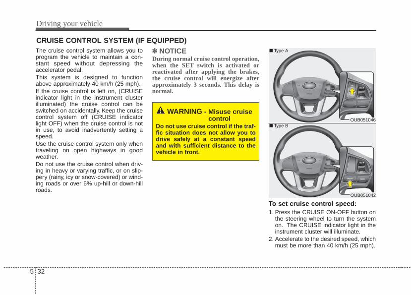
Driving your vehicle
325
The cruise control system allows you toprogram the vehicle to maintain a con-stant speed without depressing theaccelerator pedal.This system is designed to functionabove approximately 40 km/h (25 mph).If the cruise control is left on, (CRUISEindicator light in the instrument clusterilluminated) the cruise control can beswitched on accidentally. Keep the cruisecontrol system off (CRUISE indicatorlight OFF) when the cruise control is notin use, to avoid inadvertently setting aspeed.Use the cruise control system only whentraveling on open highways in goodweather.Do not use the cruise control when driv-ing in heavy or varying traffic, or on slip-pery (rainy, icy or snow-covered) or wind-ing roads or over 6% up-hill or down-hillroads.
✽✽ NOTICEDuring normal cruise control operation,when the SET switch is activated orreactivated after applying the brakes,the cruise control will energize afterapproximately 3 seconds. This delay isnormal.
To set cruise control speed:1. Press the CRUISE ON-OFF button on
the steering wheel to turn the systemon. The CRUISE indicator light in theinstrument cluster will illuminate.
2. Accelerate to the desired speed, whichmust be more than 40 km/h (25 mph).
CRUISE CONTROL SYSTEM (IF EQUIPPED)
WARNING - Misuse cruisecontrol
Do not use cruise control if the traf-fic situation does not allow you todrive safely at a constant speedand with sufficient distance to thevehicle in front.
OUB051046
OUB051042
■ Type A
■ Type B

5 33
Driving your vehicle
3. Move the lever (1) down (to SET-), andrelease it at the desired speed. TheSET indicator light in the instrumentcluster will illuminate. Release the accel-erator at the same time. The desiredspeed will automatically be maintained.
On a steep grade, the vehicle may slowdown or speed up slightly while goingdownhill.
To increase cruise control setspeed:Follow either of these procedures:• Move the lever (1) up (to RES+) and
hold it. Your vehicle will accelerate.Release the lever at the speed youwant.
• Move the lever (1) up (to RES+) andrelease it immediately. The cruisingspeed will increase by 1.6 km/h (1.0mph) each time the lever is operated inthis manner.
OUB051048
OUB051044
■ Type A
■ Type BOUB051047
OUB051043
■ Type A
■ Type B
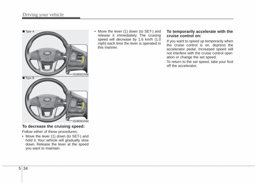
Driving your vehicle
345
To decrease the cruising speed:Follow either of these procedures:• Move the lever (1) down (to SET-) and
hold it. Your vehicle will gradually slowdown. Release the lever at the speedyou want to maintain.
• Move the lever (1) down (to SET-) andrelease it immediately. The cruisingspeed will decrease by 1.6 km/h (1.0mph) each time the lever is operated inthis manner.
To temporarily accelerate with thecruise control on:If you want to speed up temporarily whenthe cruise control is on, depress theaccelerator pedal. Increased speed willnot interfere with the cruise control oper-ation or change the set speed.To return to the set speed, take your footoff the accelerator.
OUB051048
OUB051044
■ Type A
■ Type B

5 35
Driving your vehicle
To cancel cruise control, do oneof the following:• Depress the brake pedal.• Depress the clutch pedal with a manu-
al transaxle.• Shift into N (Neutral) with an automatic
transaxle.• Press the CANCEL switch.
• Decrease the vehicle speed lower thanthe memory speed by 15 km/h (9mph).
• Decrease the vehicle speed to lessthan approximately 40 km/h (25 mph).
Each of these actions will cancel cruisecontrol operation (the SET indicator lightin the instrument cluster will go off), but itwill not turn the system off. If you wish toresume cruise control operation, movethe lever up (to RES+). You will return toyour previously preset speed.
To resume cruising speed atmore than approximately 40 km/h(25 mph):If any method other than the CRUISEON-OFF switch was used to cancelcruising speed and the system is stillactivated, the most recent set speed willautomatically resume when you movethe lever (1) up (to RES+).
OUB051049
OUB051045
■ Type A
■ Type BOUB051047
OUB051043
■ Type A
■ Type B

Driving your vehicle
365
It will not resume, however, if the vehiclespeed has dropped below approximately40 km/h (25 mph).
To turn cruise control off, do oneof the following:• Press the CRUISE ON-OFF button
(the CRUISE indicator light in theinstrument cluster will go off).
• Turn the ignition off.Both of these actions will cancel thecruise control operation. If you want toresume the cruise control operation,repeat the steps provided in “To setcruise control speed” on the previouspage.

5 37
Driving your vehicle
Your vehicle may be equipped with theISG system, which reduces fuel con-sumption by automatically shutting downthe engine, when the vehicle is at astandstill. (For example : red light, stopsign and traffic jam)The engine starts automatically as soonas the starting conditions are met.
The ISG system is ON whenever theengine is running.
✽✽ NOTICE When the engine automatically starts bythe ISG system, some warning lights(ABS, ESC, ESC OFF, ESC or Parkingbrake warning light) may turn on for afew seconds.This happens because of low batteryvoltage. It does not mean the system ismalfunctioning. Auto stop
To stop the engine in idle stop modeStop the vehicle completely by pressingthe brake pedal.You must reach a speed of at least 8km/h(5mph) since last idle stop.The engine will stop and the green AUTOSTOP indicator ( ) on the instrumentcluster will illuminate. If your vehicle isequipped with the type B cluster, thenotice will illuminate on the LCD display.
If you open the engine hood in auto stopmode, the light on the ISG OFF buttonwill illuminate and ISG system is deacti-vated. If your vehicle is equipped with thetype B cluster, the notice will illuminateon the LCD display.Turn the ignition switch to the STARTposition to start the engine manually.
ISG (IDLE STOP AND GO) SYSTEM (IF EQUIPPED)
OUB051006
OUB051007
■ Type A
■ Type BOUB051020
OUB051021

Driving your vehicle
385
Auto startTo restart the engine from idle stopmode• Release the brake pedal.• Move the shift lever in the R(reverse) or
Sports mode with pressing the brakepedal
The engine will start and the green AUTOSTOP indicator ( ) on the instrumentcluster will go out.
The engine will restart automaticallywithout the driver’s any actions if thefollowing occurs:- When the front defroster is on.- The brake vaccum pressure is low.- The battery charging status is low.- The vehicle speed exceeds 1 mph (1.6
km/h).- The fan speed is in the highest position
when the air conditioning is on.
- Engine is turned off by Auto Stop for along time.
- If you unfasten the sea belt or open thedriver's door while depressing the brakepedal.
The green AUTO STOP indicator ( )on the instrument cluster will blink for 5seconds and the notice will illuminate onthe LCD display (for type B cluster).OUB051006
OUB051019
■ Type A
■ Type B

5 39
Driving your vehicle
Condition of ISG system opera-tionThe ISG system will operate underthe following condition:- The driver’s seat belt is fastened.- The driver’s door and hood are closed.- The brake vaccum pressure is ade-
quate.- The battery is sufficiently charged.- The outside temperature is more than
28.4°F (-2°C).- The outside temperature is under
89.6°F (32°C).- The engine coolant temperature is not
low.
• If the ISG system does not meet thatoperation condition, the ISG system isdeactivated. The light on the ISG OFFbutton will illuminate.
• If the light comes on continuously,please check the operation condition.
ISG system deactivation• If you want to deactivate the ISG sys-
tem, press the ISG OFF button. Thelight on the ISG OFF button will illumi-nate and the notice will illuminate onthe LCD display (for type B cluster).
• If you press the ISG OFF button again,the system will be activated and thelight on the ISG OFF button will turnoff.
OUB051011
Type : B
OUB051022
OUB051067N

Driving your vehicle
405
ISG system malfunctionThe system may not operate when:- The ISG related sensors or system
error occurs.The yellow AUTO STOP indicator ( )on the instrument cluster will stay onafter blinking for 5 seconds and the lighton the ISG OFF button will illuminate. Ifyour vehicle is equipped with cluster typeB cluster, the notice will illuminate on theLCD display.
If the ISG OFF button light is not turnedoff by pressing the ISG OFF button againor if the ISG system continuously doesnot work correctly, please contact anauthorized Kia dealer as soon as possi-ble.
✽✽ NOTICEIf the AGM battery is reconnected orreplaced, ISG function will not operateimmediately.If you want to use the ISG function, thebattery sensor needs to be calibrated forapproximately 4 hours with the ignitionoff and then, turn the engine on and off2 or 3 times.
OUB051023
■ Type A ■ Type B
■ Type BOUB051006/OUB051059
WARNING - Engine RepairTurn the ignition switch to theLOCK (OFF) position or remove thekey from the ignition completelybefore performing work on thevehicle in the engine area. Failureto do so could result in seriousinjuries due to sudden engine reac-tivation.

5 41
Driving your vehicle
ACTIVE ECO SYSTEM (IF EQUIPPED)
Active ECO operationActive ECO helps improve fuel efficiencyby controlling the engine and transaxle.But fuel-efficiency can be changed by thedriver's driving habits and road condi-tions.• When the Active ECO button is
pressed the ECO indicator (green) willilluminate to show that the Active ECOis operating.
• When the Active ECO is activated, itdoes not turn off even though theengine is restarted again. To turn offthe system, press the active ECO but-ton again.
• If Active ECO is turned off, it will returnto the normal mode.
Limitation of Active ECO operation:If the following conditions occur whileActive ECO is operating, the systemoperation is limited even though there isno change in the ECO indicator.• When the coolant temperature is low:
The system will be limited until engineperformance becomes normal.
• When driving up a hill:The system will be limited to gainpower when driving uphill because theengine torque is restricted.
• When using sports mode:The system will be limited according tothe shift location.
• When the accelerator pedal is deeplypressed for a few seconds:The system will be limited, Judgingthat the driver wants to speed up.
OUB051066N

Driving your vehicle
425
Your vehicle's fuel economy dependsmainly on your style of driving, where youdrive and when you drive.Each of these factors affects how manymiles (kilometers) you can get from a gal-lon (liter) of fuel. To operate your vehicleas economically as possible, use the fol-lowing driving suggestions to help savemoney in both fuel and repairs:• Drive smoothly. Accelerate at a moder-
ate rate. Don't make "jack-rabbit" startsor full-throttle shifts and maintain asteady cruising speed. Don't racebetween stoplights. Try to adjust yourspeed to the traffic so you don't have tochange speeds unnecessarily. Avoidheavy traffic whenever possible.Always maintain a safe distance fromother vehicles so you can avoid unnec-essary braking. This also reducesbrake wear.
• Drive at a moderate speed. The fasteryou drive, the more fuel your vehicleuses. Driving at a moderate speed,especially on the highway, is one of themost effective ways to reduce fuel con-sumption.
• Don't "ride" the brake pedal. This canincrease fuel consumption and alsoincrease wear on these components.In addition, driving with your foot rest-ing on the brake pedal may cause thebrakes to overheat, which reducestheir effectiveness and may lead tomore serious consequences.
• Take care of your tires. Keep theminflated to the recommended pressure.Incorrect inflation, either too much ortoo little, results in unnecessary tirewear. Check the tire pressures at leastonce a month.
• Be sure that the wheels are alignedcorrectly. Improper alignment canresult from hitting curbs or driving toofast over irregular surfaces. Poor align-ment causes faster tire wear and mayalso result in other problems as well asgreater fuel consumption.
• Keep your vehicle in good condition.For better fuel economy and reducedmaintenance costs, maintain your vehi-cle in accordance with the mainte-nance schedule in section 7. If youdrive your vehicle in severe conditions,more frequent maintenance is required(see section 7 for details).
• Keep your vehicle clean. For maximumservice, your vehicle should be keptclean and free of corrosive materials. Itis especially important that mud, dirt,ice, etc. not be allowed to accumulateon the underside of the vehicle. Thisextra weight can result in increasedfuel consumption and also contributeto corrosion.
• Travel lightly. Don't carry unnecessaryweight in your vehicle. Weight reducesfuel economy.
• Don't let the engine idle longer thannecessary. If you are waiting (and notin traffic), turn off your engine andrestart only when you're ready to go.
ECONOMICAL OPERATION

5 43
Driving your vehicle
• Remember, your vehicle does notrequire extended warm-up. After theengine has started, allow the engine torun for 10 to 20 seconds prior to plac-ing the vehicle in gear. In very coldweather, however, give your engine aslightly longer warm-up period.
• Don't "lug" or "over-rev" the engine.Lugging is driving too slowly in a veryhigh gear resulting in engine bucking. Ifthis happens, shift to a lower gear.Over-revving is racing the enginebeyond its safe limit. This can be avoid-ed by shifting at the recommendedspeed.
• Use your air conditioning sparingly.The air conditioning system is operat-ed by engine power so your fuel econ-omy is reduced when you use it.
• Open windows at high speeds canreduce fuel economy.
• Fuel economy is less in crosswindsand headwinds. To help offset some ofthis loss, slow down when driving inthese conditions.
Keeping a vehicle in good operating con-dition is important both for economy andsafety. Therefore, have an authorized Kiadealer perform scheduled inspectionsand maintenance.
WARNING - Engine off dur-ing motion
Never turn the engine off to coastdown hills or anytime the vehicle isin motion. The power steering andpower brakes will not functionproperly without the engine run-ning. In addition, turning off theignition while driving could engagethe steering wheel lock resulting inloss of vehicle steering. Keep theengine on and downshift to anappropriate gear for engine brakingeffect.

Driving your vehicle
445
Hazardous driving conditions When hazardous driving conditions areencountered such as water, snow, ice,mud, sand, or similar hazards, followthese suggestions:• Drive cautiously and allow extra dis-
tance for braking.• Avoid sudden braking or steering.• When braking with non-ABS brakes
pump the brake pedal with a light up-and-down motion until the vehicle isstopped.
Do not pump the brake pedal on a vehi-cle equipped with ABS.• If stalled in snow, mud, or sand, use
second gear. Accelerate slowly toavoid spinning the drive wheels.
• Use sand, rock salt, or other non-slipmaterial under the drive wheels to pro-vide traction when stalled in ice, snow,or mud.
Rocking the vehicle If it is necessary to rock the vehicle to freeit from snow, sand, or mud, first turn thesteering wheel right and left to clear thearea around your front wheels. Then, shiftback and forth between 1st (First) and R(Reverse) in vehicles equipped with amanual transaxle or R (Reverse) and anyforward gear in vehicles equipped with anautomatic transaxle. Do not race theengine, and spin the wheels as little aspossible. If you are still stuck after a fewtries, have the vehicle pulled out by a towvehicle to avoid engine overheating andpossible damage to the transaxle.The ESC system should be turned OFFprior to rocking the vehicle.
SPECIAL DRIVING CONDITIONS
WARNING - DownshiftingDo not downshift with an automatictransaxle while driving on slipperysurfaces. The sudden change intire speed could cause the tires toskid and result in an accident.
CAUTION - Vehicle rockingProlonged rocking may causeengine overheating, transaxle dam-age or failure, and tire damage.

5 45
Driving your vehicle
Smooth corneringAvoid braking or gear changing in cor-ners, especially when roads are wet.Ideally, corners should always be takenunder gentle acceleration. If you followthese suggestions, tire wear will be heldto a minimum.
Driving at night Because night driving presents morehazards than driving in the daylight, hereare some important tips to remember:• Slow down and keep more distance
between you and other vehicles, as itmay be more difficult to see at night,especially in areas where there maynot be any street lights.
OUN056051 OMC035004WARNING - Sudden vehicle movement
Do not attempt to rock the vehicle ifpeople or objects are nearby. Thevehicle may suddenly move for-ward or backwards as it becomesunstuck.
CAUTION - Spinning tiresDo not spin the wheels, especiallyat speeds more than 56 km/h (35mph). Spinning the wheels at highspeeds when the vehicle is station-ary could cause a tire to overheatwhich could result in tire damage.

Driving your vehicle
465
• Adjust your mirrors to reduce the glarefrom other driver's headlights.
• Keep your headlights clean and prop-erly aimed on vehicles not equippedwith the automatic headlight aimingfeature. Dirty or improperly aimedheadlights will make it much more diffi-cult to see at night.
• Avoid staring directly at the headlightsof oncoming vehicles. You could betemporarily blinded, and it will takeseveral seconds for your eyes to read-just to the darkness.
Driving in the rain Rain and wet roads can make drivingdangerous, especially if you’re not pre-pared for the slick pavement. Here are afew things to consider when driving in therain:• A heavy rainfall will make it harder to
see and will increase the distanceneeded to stop your vehicle, so slowdown.
• Keep your windshield wiping equip-ment in good shape. Replace yourwindshield wiper blades when theyshow signs of streaking or missingareas on the windshield.
• If your tires are not in good condition,making a quick stop on wet pavementcan cause a skid and possibly lead toan accident. Be sure your tires are ingood shape.
• Turn on your headlights to make it eas-ier for others to see you.
• Driving too fast through large puddlescan affect your brakes. If you must gothrough puddles, try to drive throughthem slowly.
• If you believe you may have gottenyour brakes wet, apply them lightlywhile driving until normal braking oper-ation returns.
Driving in flooded areas Avoid driving through flooded areasunless you are sure the water is no high-er than the bottom of the wheel hub.Drive through any water slowly. Allowadequate stopping distance becausebrake performance may be affected.After driving through water, dry thebrakes by gently applying them severaltimes while the vehicle is moving slowly.
1JBB3303

5 47
Driving your vehicle
Highway drivingTires Adjust the tire inflation pressures tospecification. Low tire inflation pressureswill result in overheating and possiblefailure of the tires.Avoid using worn or damaged tires whichmay result in reduced traction or tire fail-ure.Never exceed the maximum tire inflationpressure shown on the tires.
Fuel, engine coolant and engine oilHigh speed travel consumes more fuelthan urban motoring. Do not forget tocheck both the engine coolant andengine oil.
Drive beltA loose or damaged drive belt may over-heat the engine.
WARNING - Under/overinflated tires
Always check the tires for properinflation before driving.Underinflated or overinflated tirescan cause poor handling, loss ofvehicle control, and sudden tire fail-ure leading to accidents, injuries,and even death. For proper tirepressures, refer to “Tires andwheels” in section 8.
WARNING - Tire treadAlways check the tire tread beforedriving your vehicle. Worn-out tirescan result in loss of vehicle control.Worn-out tires should be replacedas soon as possible. For furtherinformation and tread limits, referto "Tires and wheels" in section 7.

Driving your vehicle
485
Severe weather conditions in the winterresult in greater wear and other prob-lems. To minimize the problems of winterdriving, you should follow these sugges-tions:
Snowy or Icy conditionsTo drive your vehicle in deep snow, it maybe necessary to use snow tires on yourtires. If snow tires are needed, it is nec-essary to select tires equivalent in sizeand type of the original equipment tires.Failure to do so may adversely affect thesafety and handling of your car.Furthermore, speeding, rapid accelera-tion, sudden brake applications, andsharp turns are potentially very haz-ardous practices.During deceleration, use engine brakingto the fullest extent. Sudden brake appli-cations on snowy or icy roads may causeskids. You need to keep sufficient dis-tance between the vehicle in operation infront and your vehicle. Also, apply thebrake gently.
Snow tiresIf you mount snow tires on your vehicle,make sure they are radial tires of thesame size and load range as the originaltires. Mount snow tires on all four wheelsto balance your vehicle’s handling in allweather conditions. Keep in mind that thetraction provided by snow tires on dryroads may not be as high as your vehi-cle's original equipment tires. You shoulddrive cautiously even when the roads areclear. Check with the tire dealer for max-imum speed recommendations.Do not install studded tires without firstchecking local, state and municipal regu-lations for possible restrictions againsttheir use.
WINTER DRIVING
OBH058040

5 49
Driving your vehicle
Use high quality ethylene glycolcoolantYour vehicle is delivered with high qualityethylene glycol coolant in the coolingsystem. It is the only type of coolant thatshould be used because it helps preventcorrosion in the cooling system, lubri-cates the water pump and preventsfreezing. Be sure to replace or replenishyour coolant in accordance with themaintenance schedule in section 7.Before winter, have your coolant tested toassure that its freezing point is sufficientfor the temperatures anticipated duringthe winter.
Check battery and cablesWinter puts additional burdens on thebattery system. Visually inspect the bat-tery and cables as described in section7. The level of charge in your battery canbe checked by an authorized Kia dealeror a service station.
Change to "winter weight" oil ifnecessaryIn some climates it is recommended thata lower viscosity "winter weight" oil beused during cold weather. See section 8for recommendations. If you aren't surewhat weight oil you should use, consultan authorized Kia dealer.
Check spark plugs and ignitionsystemInspect your spark plugs as described insection 7 and replace them if necessary.Also check all ignition wiring and compo-nents to be sure they are not cracked,worn or damaged in any way.
To keep locks from freezingTo keep the locks from freezing, squirt anapproved de-icer fluid or glycerine intothe key opening. If a lock is covered withice, squirt it with an approved de-icingfluid to remove the ice. If the lock isfrozen internally, you may be able to thawit out by using a heated key. Handle theheated key with care to avoid injury.
Use approved window washeranti-freeze in systemTo keep the water in the window washersystem from freezing, add an approvedwindow washer anti-freeze solution inaccordance with instructions on the con-tainer. Window washer anti-freeze isavailable from an authorized Kia dealerand most auto parts outlets. Do not useengine coolant or other types of anti-freeze as these may damage the paintfinish.

Driving your vehicle
505
Don't let your parking brakefreezeUnder some conditions your parkingbrake can freeze in the engaged position.This is most likely to happen when thereis an accumulation of snow or ice aroundor near the rear brakes or if the brakesare wet. If there is a risk the parkingbrake may freeze, apply it only temporar-ily while you put the shift lever in P (auto-matic transaxle) or in first or reverse gear(manual transaxle) and block the rearwheels so the vehicle cannot roll. Thenrelease the parking brake.
Don't let ice and snow accumu-late underneathUnder some conditions, snow and icecan build up under the fenders and inter-fere with the steering. When driving insevere winter conditions where this mayhappen, you should periodically checkunderneath the car to be sure the move-ment of the front wheels and the steeringcomponents is not obstructed.
Carry emergency equipmentDepending on the severity of the weath-er you should carry appropriate emer-gency equipment. Some of the items youmay want to carry include tow straps orchains, flashlight, emergency flares,sand, a shovel, jumper cables, a windowscraper, gloves, ground cloth, coveralls, ablanket, etc.
We do not recommend using thisvehicle for trailer towing.
TRAILER TOWING

5 51
Driving your vehicle
Tire and loading information labelThe label located on the driver's doorsill gives the original tire size, coldtire pressures recommended for yourvehicle, the number of people thatcan be in your vehicle and vehiclecapacity weight.
Vehicle capacity weight:385 kg (849 lb)
Vehicle capacity weight is the maxi-mum combined weight of occupantsand cargo. If your vehicle is equippedwith a trailer, the combined weightincludes the tongue load.
VEHICLE LOAD LIMIT
OUB061016N/OUB061015N/OUB061018N OUB061014N/OUB061019N/OUB061017N

Driving your vehicle
525
Seating capacity:Total : 5 persons
(Front seat : 2 persons, Rear seat : 3 persons)
Seating capacity is the maximumnumber of occupants including adriver, your vehicle may carry.However, the seating capacity maybe reduced based upon the weight ofall of the occupants, and the weightof the cargo being carried or towed.Do not overload the vehicle as thereis a limit to the total weight, or loadlimit including occupants and cargo,the vehicle can carry.
Towing capacity:We do not recommend using thisvehicle for trailer towing.
Cargo capacity:The cargo capacity of your vehiclewill increase or decrease dependingon the weight and the number ofoccupants and the tongue load, ifyour vehicle is equipped with a trailer.
Steps For Determining Correct LoadLimit -1. Locate the statement "The com-
bined weight of occupants andcargo should never exceed XXXkg or XXX lbs.'' on your vehicle'splacard.
2. Determine the combined weight ofthe driver and passengers that willbe riding in your vehicle.
3. Subtract the combined weight ofthe driver and passengers fromXXX kg or XXX lbs.
4. The resulting figure equals theavailable amount of cargo and lug-gage load capacity. For example, ifthe "XXX" amount equals 635 kg(1400 lbs.) and there will be five 68kg (150 lbs.) passengers in yourvehicle, the amount of availablecargo and luggage load capacityis 295 kg (650 lbs).(635-340 (5 x 68) = 295 kg or1400-750 (5 x 150) = 650 lbs.)
5. Determine the combined weight ofluggage and cargo being loadedon the vehicle. That weight maynot safely exceed the availablecargo and luggage load capacitycalculated in Step 4.
6. If your vehicle will be towing a trail-er, load from your trailer will betransferred to your vehicle. Consultthis manual to determine how thisreduces the available cargo andluggage load capacity of yourvehicle.

5 53
Driving your vehicle
C190F03JM
Item Description Total
AVehicle Capacity 420 kg
Weight (926 lbs)Subtract Occupant
B Weight 365 kg
73 kg (161 lbs) × 5(805 lbs)
CAvailable Cargo and 55 kg
Luggage weight (121 lbs)
A B C
Example 3
C190F02JM
Item Description Total
AVehicle Capacity 420 kg
Weight (926 lbs)Subtract Occupant
B Weight 340 kg
68 kg (150 lbs) × 5(750 lbs)
CAvailable Cargo and 80 kg
Luggage weight (176 lbs)
A B C
Example 2
C190F01JM
Item Description Total
AVehicle Capacity 420 kg
Weight (926 lbs)Subtract Occupant
B Weight 136 kg
68 kg (150 lbs) × 2(300 lbs)
CAvailable Cargo and 284 kg
Luggage weight (626 lbs)
Example 1
A B C
Refer to your vehicle’s tire and loading information label for specific information about your vehicle's capacity weightand seating positions. The combined weight of the driver, passengers and cargo should never exceed your vehicle'scapacity weight.

Driving your vehicle
545
Certification labelThe certification label is located onthe driver's door sill at the center pil-lar.This label shows the maximumallowable weight of the fully loadedvehicle. This is called the GVWR(Gross Vehicle Weight Rating). TheGVWR includes the weight of thevehicle, all occupants, fuel andcargo.This label also tells you the maxi-mum weight that can be supportedby the front and rear axles, calledGross Axle Weight Rating (GAWR).To find out the actual loads on yourfront and rear axles, you need to goto a weigh station and weigh yourvehicle.Your dealer can help you withthis. Be sure to spread out your loadequally on both sides of the center-line.
The label will help you decide howmuch cargo and installed equipmentyour vehicle can carry.
If you carry items inside your vehicle- like suitcases, tools, packages, oranything else - they are moving asfast as the vehicle. If you have to stopor turn quickly, or if there is a crash,the items will keep going and cancause an injury if they strike the driv-er or a passenger.
WARNING - Over loadingNever exceed the GVWR foryour vehicle, the GAWR foreither the front or rear axle andvehicle capacity weight.Exceeding these ratings canaffect your vehicle’s handlingand braking ability.

5 55
Driving your vehicle
✽✽ NOTICEOverloading your vehicle may causedamage. Repairs would not be cov-ered by your warranty. Do not over-load your vehicle.
WARNING - Over loadingDo not overload your vehicle.Overloading your vehicle cancause heat buildup in your vehi-cle's tires and possible tire fail-ure, increased stopping dis-tances and poor vehicle han-dling--all of which may result ina crash.
WARNING - Loose cargoDo not travel with unsecuredblunt objects in the passengercompartment of your vehicle(e.g. suit cases or unsecuredchild seats). These items maystrike occupant during a sud-den stop or crash.

Driving your vehicle
565
This section will guide you in the properloading of your vehicle and/or trailer, tokeep your loaded vehicle weight within itsdesign rating capability, with or without atrailer. Properly loading your vehicle willprovide maximum return of the vehicledesign performance. Before loading yourvehicle, familiarize yourself with the fol-lowing terms for determining your vehi-cle's weight ratings, with or without atrailer, from the vehicle's specificationsand the compliance label:
Base curb weight This is the weight of the vehicle includinga full tank of fuel and all standard equip-ment. It does not include passengers,cargo, or optional equipment.
Vehicle curb weightThis is the weight of your new vehiclewhen you picked it up from your dealerplus any aftermarket equipment.
Cargo weightThis figure includes all weight added tothe Base Curb Weight, including cargoand optional equipment.
GAW (Gross axle weight)This is the total weight placed on eachaxle (front and rear) - including vehiclecurb weight and all payload.
GAWR (Gross axle weight rating)This is the maximum allowable weightthat can be carried by a single axle (frontor rear). These numbers are shown onthe compliance label.The total load on each axle must neverexceed its GAWR.
GVW (Gross vehicle weight)This is the Base Curb Weight plus actualCargo Weight plus passengers.
GVWR (Gross vehicle weight rating)This is the maximum allowable weight ofthe fully loaded vehicle (including alloptions, equipment, passengers andcargo). The GVWR is shown on the cer-tification label located on the driver’sdoor sill.
VEHICLE WEIGHT

6
Road warning / 6-2In case of an emergency while driving / 6-2If the engine will not start / 6-3Emergency starting / 6-4If the engine overheats / 6-7Tire pressure monitoring system (TPMS) / 6-8If you have a flat tire / 6-13, 21Towing / 6-27
What to do in an emergency

What to do in an emergency
26
ROAD WARNING
Hazard warning flasher The hazard warning flasher serves as awarning to other drivers to exerciseextreme caution when approaching,overtaking, or passing your vehicle.
It should be used whenever emergencyrepairs are being made or when the vehi-cle is stopped near the edge of a road-way.Depress the flasher switch with the igni-tion switch in any position. The flasherswitch is located in the center consoleswitch panel. All turn signal lights willflash simultaneously.
• The hazard warning flasher operateswhether your vehicle is running or not.
• The turn signals do not work when thehazard flasher is on.
• Care must be taken when using thehazard warning flasher while the vehi-cle is being towed.
If the engine stalls at a crossroador crossingIf the engine stalls at a crossroad orcrossing, set the shift lever in the N(Neutral) position and then push the vehi-cle to a safe place.
If you have a flat tire while drivingIf a tire goes flat while you are driving:1.Take your foot off the accelerator pedal
and let the vehicle slow down whiledriving straight ahead. Do not apply thebrakes immediately or attempt to pulloff the road as this may cause a loss ofcontrol. When the vehicle has sloweddown to such a speed that it is safe todo so, brake carefully and pull off theroad. Drive off the road as far as possi-ble and park on a firm level ground. Ifyou are on a divided highway, do notpark in the median area between thetwo traffic lanes.
IN CASE OF AN EMERGENCYWHILE DRIVING
OUB041094

6 3
What to do in an emergency
2.When the vehicle is stopped, turn onyour emergency hazard flashers, setthe parking brake and put the transaxlein P (automatic transaxle) or reverse(manual transaxle).
3.Have all passengers get out of thevehicle. Be sure they all get out on theside of the vehicle that is away fromtraffic.
4.When changing a flat tire, follow theinstruction provided later in this sec-tion.
If engine stalls while driving1. Reduce your speed gradually, keeping
a straight line. Move cautiously off theroad to a safe place.
2. Turn on your emergency flashers.3. Try to start the engine again. If your
vehicle will not start, contact anauthorized Kia dealer or seek otherqualified assistance.
If the engine doesn't turn over orturns over slowly1. If your vehicle has an automatic
transaxle, be sure the shift lever is in N(Neutral) or P (Park) and the emer-gency brake is set.
2. Check the battery connections to besure they are clean and tight.
3. Turn on the interior light. If the lightdims or goes out when you operate thestarter, the battery is discharged.
4. Check the starter connections to besure they are securely tightened.
5. Do not push or pull the vehicle to startit. See instructions for "Jump starting".
If engine turns over normally butdoes not start1. Check fuel level.2. With the ignition switch in the LOCK
position, check all connectors at theignition coil and spark plugs.Reconnect any that may be discon-nected or loose.
3. Check the fuel line in the engine com-partment.
4. If the engine still does not start, call anauthorized Kia dealer or seek otherqualified assistance.
IF THE ENGINE WILL NOT START
WARNING - Push/pull startDo not push or pull the vehicle tostart it. Push or pull starting maycause the catalytic converter tooverload and create a fire hazard.

What to do in an emergency
46
EMERGENCY STARTING
Connect cables in numerical order anddisconnect in reverse order.
Jump starting Jump starting can be dangerous if doneincorrectly. Therefore, to avoid harm toyourself or damage to your vehicle orbattery, follow these jump starting proce-dures. If in doubt, we strongly recom-mend that you have a competent techni-cian or towing service jump start yourvehicle.
CAUTION - 12 volt batteryUse only a 12-volt jumper system.You can damage a 12-volt startingmotor, ignition system, and otherelectrical parts beyond repair byuse of a 24-volt power supply (eithertwo 12-volt batteries in series or a24-volt motor generator set).
WARNING - BatteryKeep all flames or sparks awayfrom the battery. The battery pro-duces hydrogen gas which willexplode if exposed to flame orsparks.
WARNING - BatteryNever attempt to check the elec-trolyte level of the battery as thismay cause the battery to rupture orexplode.
WARNING - Frozen batteries
Do not attempt to jump start thevehicle if the discharged battery isfrozen or if the electrolyte level islow as the battery may rupture orexplode.
WARNING - Sulfuric acidrisk
When jump starting your vehicle becareful not to get acid on yourself,your clothing or on the vehicle.Automobile batteries contain sulfu-ric acid. This is poisonous andhighly corrosive.
1VQA4001
Discharged battery
Jumper Cables
Booster battery
(-)
(+)
(+)(-)

6 5
What to do in an emergency
Jump starting procedure Absorbent Glass Matt (AGM) batteriesare maintenance-free and should only beserviced by an authorized Kia dealer. Forcharging your AGM battery, use only fullyautomatic battery chargers that are spe-cially developed for AGM batteries.When replacing the AGM battery, useonly the Kia genuine battery for the ISGsystem.
✽✽ NOTICEIf the AGM battery is reconnected orreplaced, ISG function will not operateimmediately.If you want to use the ISG function, thebattery sensor needs to be calibrated forapproximately 4 hours with the ignitionoff and then, turn the engine on and off2 or 3 times.
1. Make sure the booster battery is 12-volt and that its negative terminal isgrounded.
2. If the booster battery is in anothervehicle, do not allow the vehicles totouch.
3. Turn off all unnecessary electricalloads.
4. Connect the jumper cables in the exactsequence shown in the illustration.First connect one end of a jumpercable to the positive terminal of thedischarged battery (1), then connectthe other end to the positive terminalon the booster battery (2).Proceed to connect one end of theother jumper cable to the negative ter-minal of the booster battery (3), thenthe other end to a solid, stationary,metallic point (for example, the enginelifting bracket) away from the battery(4). Do not connect it to or near anypart that moves when the engine iscranked.
Do not allow the jumper cables to con-tact anything except the correct batteryterminals or the correct ground. Do notlean over the battery when makingconnections.
5. Start the engine of the vehicle with thebooster battery and let it run at 2,000rpm, then start the engine of the vehi-cle with the discharged battery.
If the cause of your battery discharging isnot apparent, you should have your vehi-cle checked by an authorized Kia dealer.
CAUTION - Battery cablesDo not connect the jumper cablefrom the negative terminal of thebooster battery to the negative ter-minal of the discharged battery.This can cause the discharged bat-tery to overheat and crack, releas-ing battery acid.
CAUTION - AGM batterycap
Do not open or remove the cap ontop of the battery. This may causethe leak of dangerous internal elec-trolytes.

What to do in an emergency
66
Push-starting Your manual transaxle-equipped vehicleshould not be push-started because itmight damage the emission control sys-tem.Vehicles equipped with automatictransaxle cannot be push-started.Follow the directions in this section forjump-starting.
WARNING - Tow startingvehicle
Never tow a vehicle to start itbecause the sudden surge forwardwhen the engine starts could causea collision with the tow vehicle.
6 7
What to do in an emergency
IF THE ENGINE OVERHEATSIf your temperature gauge indicates over-heating, you will experience a loss ofpower, or hear loud pinging or knocking,the engine is probably too hot. If this hap-pens, you should:
1. Pull off the road and stop as soon as itis safe to do so.
2. Place the shift lever in P (automatictransaxle) or neutral (manualtransaxle) and set the parking brake. Ifthe air conditioning is on, turn it off.
3. If engine coolant is running out underthe vehicle or steam is coming outfrom underneath the hood, stop theengine. Do not open the hood until thecoolant has stopped running or thesteaming has stopped. If there is novisible loss of engine coolant and nosteam, leave the engine running andcheck to be sure the engine coolingfan is operating. If the fan is not run-ning, turn the engine off.
4. Check to see if the water pump drivebelt is missing. If it is not missing,check to see that it is tight. If the drivebelt seems to be satisfactory, check forcoolant leaking from the radiator,hoses or under the vehicle. (If the airconditioning had been in use, it is nor-mal for cold water to be draining fromit when you stop).
5. If the water pump drive belt is brokenor engine coolant leaks, stop theengine immediately and call the near-est authorized Kia dealer for assis-tance.
6. If you cannot find the cause of theoverheating, wait until the engine tem-perature has returned to normal. Then,if coolant has been lost, carefully addcoolant to the reservoir to bring thefluid level in the reservoir up to thehalfway mark.
7.Proceed with caution, keeping alert forfurther signs of overheating. If over-heating happens again, call an author-ized Kia dealer for assistance.
Serious loss of coolant indicates there isa leak in the cooling system and thisshould be checked as soon as possibleby an authorized Kia dealer.
WARNING - Under thehood
While the engine is running, keephair, hands and clothing away frommoving parts such as the fan anddrive belts.
WARNING - Radiator capDo not remove the radiator capwhen the engine is hot. This canallow coolant to be blown out of theopening and cause serious burns.

What to do in an emergency
86
TIRE PRESSURE MONITORING SYSTEM (TPMS) (IF EQUIPPED)
(1) Low tire pressure telltale / TPMS malfunction indicator
Each tire, including the spare (if pro-vided), should be checked monthlywhen cold and inflated to the inflationpressure recommended by the vehi-cle manufacturer on the vehicle plac-ard or tire inflation pressure label. (Ifyour vehicle has tires of a differentsize than the size indicated on thevehicle placard or tire inflation pres-sure label, you should determine theproper tire inflation pressure forthose tires.)
As an added safety feature, yourvehicle has been equipped with a tirepressure monitoring system (TPMS)that illuminates a low tire pressuretelltale when one or more of yourtires is significantly under-inflated.Accordingly, when the low tire pres-sure telltale illuminates, you shouldstop and check your tires as soon aspossible, and inflate them to theproper pressure. Driving on a signifi-cantly under-inflated tire causes thetire to overheat and can lead to tirefailure. Under-inflation also reducesfuel efficiency and tire tread life, andmay affect the vehicle’s handling andstopping ability.
Please note that the TPMS is not asubstitute for proper tire mainte-nance, and it is the driver’s responsi-bility to maintain correct tire pres-sure, even if under-inflation has notreached the level to trigger illumina-tion of the TPMS low tire pressuretelltale.
Your vehicle has also been equippedwith a TPMS malfunction indicator toindicate when the system is notoperating properly. The TPMS mal-function indicator is combined withthe low tire pressure telltale. Whenthe system detects a malfunction,the telltale will flash for approximate-ly one minute and then remain con-tinuously illuminated. This sequencewill continue upon subsequent vehi-cle start-ups as long as the malfunc-tion exists. When the malfunctionindicator is illuminated, the systemmay not be able to detect or signallow tire pressure as intended. TPMSmalfunctions may occur for a varietyof reasons, including the installationof replacement or alternate tires orwheels on the vehicle that preventthe TPMS from functioning properly.Always check the TPMS malfunctiontelltale after replacing one or moretires or wheels on your vehicle toensure that the replacement or alter-nate tires and wheels allow theTPMS to continue to function proper-ly.
WK-14

6 9
What to do in an emergency
If the TPMS indicator does not illumi-nate for 3 seconds when the ignitionswitch is turned to the ON position orengine is running, or If it comes onafter blinking for approximately oneminute, take your car to your nearestauthorized kia dealer and have thesystem checked.
Low tire pressure tell-tale
When the tire pressure monitoringsystem warning indicator is illuminat-ed, one or more of your tires is sig-nificantly under-inflated.If the telltale illuminates, immediatelyreduce your speed, avoid hard cor-nering and anticipate increased stop-ping distances. You should stop andcheck your tires as soon as possible.Inflate the tires to the proper pres-sure as indicated on the vehicle’splacard or tire inflation pressure labellocated on the driver’s side center pil-lar outer panel. If you cannot reach aservice station or if the tire cannothold the newly added air, replace thelow pressure tire with the spare tire.Then the Low Tire Pressure telltalemay flash for approximately oneminute and then remain continuouslyilluminated after restarting and about20 minutes of continuous drivingbefore you have the low pressure tirerepaired and replaced on the vehicle.
In winter or cold weather, the low tirepressure telltale may be illuminated ifthe tire pressure was adjusted to therecommended tire inflation pressurein warm weather. It does not meanyour TPMS is malfunctioningbecause the decreased temperatureleads to a proportional lowering oftire pressure.When you drive your vehicle from awarm area to a cold area or from acold area to a warm area, or the out-side temperature is greatly higher orlower, you should check the tire infla-tion pressure and adjust the tires tothe recommended tire inflation pres-sure.

What to do in an emergency
106
TPMS (Tire PressureMonitoring System)malfunction indicator
The TPMS malfunction indicator willilluminate after it blinks for approxi-mately one minute when there is aproblem with the Tire PressureMonitoring System. If the system isable to correctly detect an under infla-tion warning at the same time as sys-tem failure then it will illuminate theTPMS malfunction indicator.Have the system checked by anauthorized kia dealer as soon aspossible to determine the cause ofthe problem.The TPMS malfunction indicator maybe illuminated if the vehicle is movingaround electric power supply cablesor radios transmitter such as atpolice stations, government and pub-lic offices, broadcasting stations, mil-itary installations, airports, or trans-mitting towers, etc. This can interferewith normal operation of the TirePressure Monitoring System(TPMS).
The TPMS malfunction indicator mayilluminate if snow chains or someseparately purchased devices suchas notebook computers, mobilecharger, remote starter, navigationetc. are used in the vehicle. This caninterfere with normal operation of theTire Pressure Monitoring System(TPMS).
WARNING - Low pressuredamage
Do not drive on low pressuretires. Significantly low tire pres-sure can cause the tires to over-heat and fail making the vehicleunstable resulting in increasedbraking distances and a loss ofvehicle control.
6 11
What to do in an emergency
Changing a tire with TPMSIf you have a flat tire, the Low TirePressure will come on. Have the flattire repaired by an authorized Kiadealer as soon as possible orreplace the flat tire with the sparetire.
Each wheel is equipped with a tirepressure sensor mounted inside thetire behind the valve stem. You mustuse TPMS specific wheels. It is rec-ommended that you always haveyour tires serviced by an authorizedKia dealer.
Even if you replace the low pressuretire with the spare tire, the Low TirePressure Telltale will blink or remainon until the low pressure tire isrepaired and placed on the vehicle.After you replace the low pressuretire with, the TPMS spare tire, theLow Tire Pressure telltale may blinkor illuminate after a few minutesbecause the TPMS sensor mountedon the spare wheel is not initiated.Once the low pressure tire is reinflat-ed to the recommended pressureand installed on the vehicle or theTPMS sensor mounted on thereplaced spare wheel is initiated byan authorized Kia dealer, the TPMSmalfunction indicator and the low tirepressure telltale will extinguish withina few minutes of driving.If the indicator is not extinguishedafter a few minutes of driving, pleasevisit an authorized Kia dealer.
If original mounted tire is replacedwith the spare tire, the TPMS sensoron the replaced spare wheel shouldbe initiated and the TPMS sensor onthe original mounted wheel shouldbe deactivated. If the TPMS sensoron the original mounted wheel locat-ed in the spare tire carrier still acti-vates, the tire pressure monitoringsystem may not operate properly.Have the tire with TPMS serviced orreplaced by an authorized kia dealer.
CAUTIONNever use a puncture-repairingagent not approved by Kia torepair and/or inflate a low pres-sure tire. The tire sealant notapproved by Kia may damagethe tire pressure sensor. Thesealant on the tire pressure sen-sor and wheel shall be eliminat-ed when you replace the tirewith a new one.

What to do in an emergency
126
You may not be able identify a lowtire by simply looking at it. Alwaysuse a good quality tire pressuregauge to measure the tire's inflationpressure. Please note that a tire thatis hot (from being driven) will have ahigher pressure measurement than atire that is cold.A cold tire means the vehicle hasbeen sitting for 3 hours and driven forless than 1.6 km (1 mile) in that 3hour period.Allow the tire to cool before measur-ing the inflation pressure. Always besure the tire is cold before inflating tothe recommended pressure.The TPMS cannot alert you to severeand sudden tire damage caused byexternal factors such as nails or roaddebris.If you feel any vehicle instability,immediately take your foot off theaccelerator, apply the brakes gradu-ally and with light force, and slowlymove to a safe position off the road.
✽✽ NOTICETampering with, modifying, or dis-abling the Tire Pressure MonitoringSystem (TPMS) components mayinterfere with the system's ability towarn the driver of low tire pressureconditions and/or TPMS malfunc-tions. Tampering with, modifying,or disabling the Tire PressureMonitoring System (TPMS) compo-nents may void the warranty forthat portion of the vehicle.
This device complies with IndustryCanada Standard RSS-210.Operation is subject to the followingtwo conditions:1.This device may not cause harmful
interference, and 2.This device must accept any inter-
ference received, including inter-ference that may cause undesiredoperation.
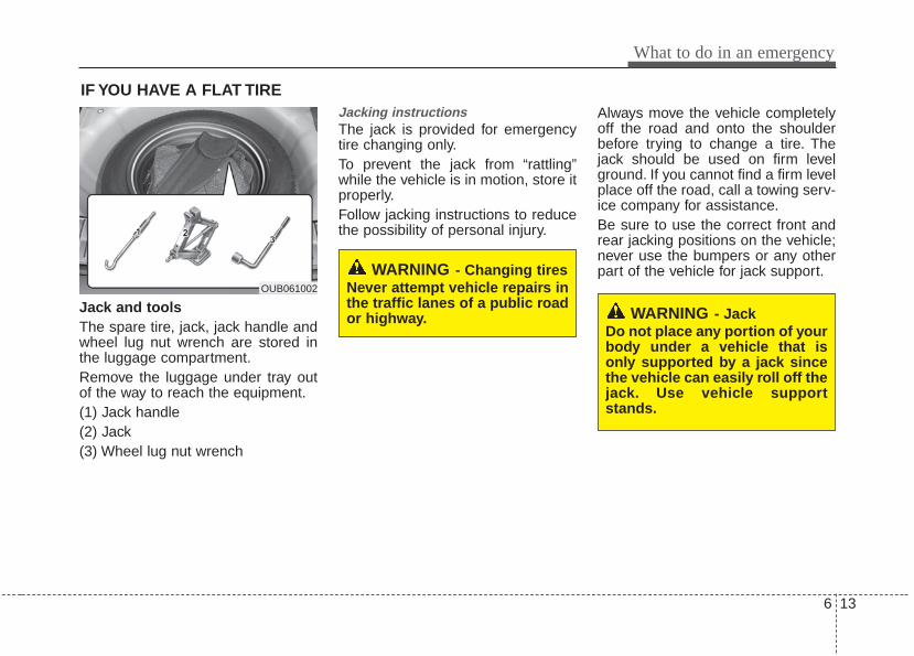
6 13
What to do in an emergency
IF YOU HAVE A FLAT TIRE
Jack and toolsThe spare tire, jack, jack handle andwheel lug nut wrench are stored inthe luggage compartment.Remove the luggage under tray outof the way to reach the equipment.(1) Jack handle(2) Jack(3) Wheel lug nut wrench
Jacking instructions The jack is provided for emergencytire changing only.To prevent the jack from “rattling”while the vehicle is in motion, store itproperly.Follow jacking instructions to reducethe possibility of personal injury.
Always move the vehicle completelyoff the road and onto the shoulderbefore trying to change a tire. Thejack should be used on firm levelground. If you cannot find a firm levelplace off the road, call a towing serv-ice company for assistance.Be sure to use the correct front andrear jacking positions on the vehicle;never use the bumpers or any otherpart of the vehicle for jack support.
WARNING - JackDo not place any portion of yourbody under a vehicle that isonly supported by a jack sincethe vehicle can easily roll off thejack. Use vehicle supportstands.
WARNING - Changing tiresNever attempt vehicle repairs inthe traffic lanes of a public roador highway.
OUB061002
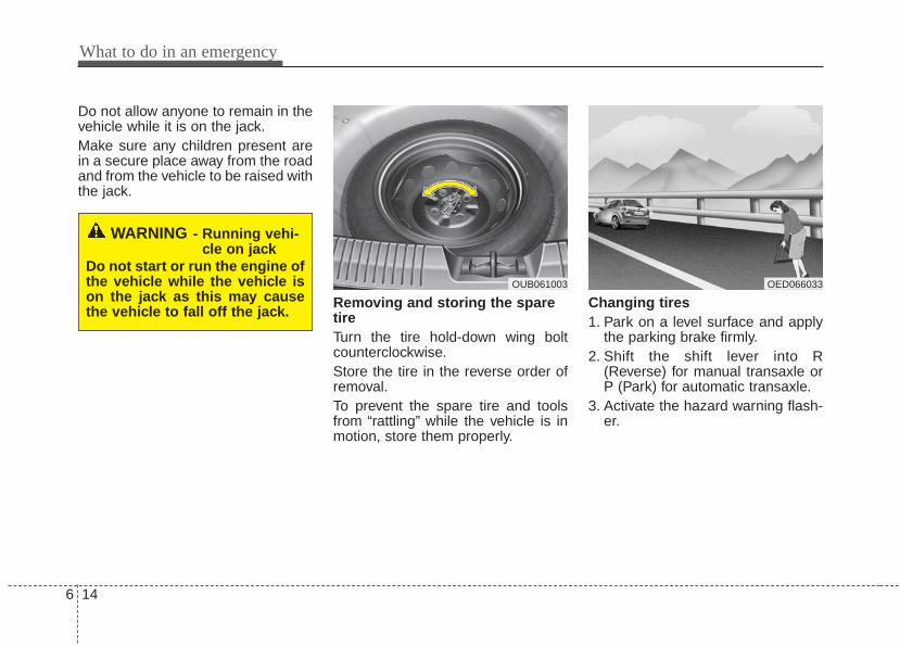
What to do in an emergency
146
Do not allow anyone to remain in thevehicle while it is on the jack.Make sure any children present arein a secure place away from the roadand from the vehicle to be raised withthe jack.
Removing and storing the sparetire Turn the tire hold-down wing boltcounterclockwise.Store the tire in the reverse order ofremoval.To prevent the spare tire and toolsfrom “rattling” while the vehicle is inmotion, store them properly.
Changing tires 1. Park on a level surface and apply
the parking brake firmly.2. Shift the shift lever into R
(Reverse) for manual transaxle orP (Park) for automatic transaxle.
3. Activate the hazard warning flash-er.
OED066033
WARNING - Running vehi-cle on jack
Do not start or run the engine ofthe vehicle while the vehicle ison the jack as this may causethe vehicle to fall off the jack.
OUB061003

6 15
What to do in an emergency
4. Remove the wheel lug nut wrench,jack, jack handle, and spare tirefrom the vehicle.
5. Block both the front and rear of thewheel that is diagonally oppositethe jack position.
To prevent vehicle movement whilechanging a tire, always set the park-ing brake fully, and always block thewheel diagonally opposite the wheelbeing changed.We recommend that the wheels ofthe vehicle be chocked, and that noperson remain in a vehicle that isbeing jacked.
6. Loosen the wheel lug nuts coun-terclockwise one turn each, but donot remove any nut until the tirehas been raised off the ground.
1VQA4023 OUB061005

What to do in an emergency
166
7. Place the jack at the front or rearjacking position closest to the tireyou are changing. Place the jackat the designated locations underthe frame. The jacking positionsare plates welded to the framewith two tabs and a raised dot toindex with the jack.
8. Insert the jack handle into the jackand turn it clockwise, raising thevehicle until the tire just clears theground. This measurement isapproximately 30 mm (1 in). Beforeremoving the wheel lug nuts, makesure the vehicle is stable and thatthere is no chance for movement orslippage.
9. Loosen the wheel nuts andremove them with your fingers.Slide the wheel off the studs andlay it flat so it cannot roll away. Toput the wheel on the hub, pick upthe spare tire, line up the holeswith the studs and slide the wheelonto them. If this is difficult, tip thewheel slightly and get the top holein the wheel lined up with the topstud. Then jiggle the wheel backand forth until the wheel can beslid over the other studs.
OUB061008 OUB061006

6 17
What to do in an emergency
Wheels and wheel covers may havesharp edges. Handle them carefullyto avoid possible injury. Before put-ting the wheel into place, be surethat there is nothing on the hub orwheel (such as mud, tar, gravel, etc.)that prevents with the wheel from fit-ting solidly against the hub.
10. To install the wheel, hold it on thestuds, put the wheel nuts on thestuds and tighten them fingertight. Jiggle the tire to be sure it iscompletely seated, then tightenthe nuts as much as possiblewith your fingers again.
11. Lower the vehicle to the groundby turning the wheel nut wrenchcounterclockwise.
Then position the wrench as shown inthe drawing and tighten the wheel nuts.Be sure the socket is seated complete-ly over the nut. Do not stand on thewrench handle or use an extensionpipe over the wrench handle.Go around the wheel tightening everynut following the numerical sequenceshown in the image until they are tight.Then double-check each nut for tight-ness. After changing the wheels, havean authorized Kia dealer tighten thewheel nuts to their proper torque assoon as possible.Wheel nut tightening torque:Steel wheel & aluminium alloy wheel:9~11 kg.m (65~79 lb.ft)
WARNING - Installing awheel
Make sure the wheel makesgood contact with the hub wheninstalled. If the contact of themounting surface between thewheel and hub is not good, thewheel nuts could come looseand cause the loss of a wheel.Loss of a wheel may result inloss of control of the vehicle.
OUB061007
What to do in an emergency
186
If you have a tire gauge, remove thevalve cap and check the air pressure.If the pressure is lower than recom-mended, drive slowly to the nearestservice station and inflate to the cor-rect pressure. If it is too high, adjustit until it is correct. Always reinstallthe valve cap after checking oradjusting the tire pressure. If the capis not replaced, air may leak from thetire. If you lose a valve cap, buyanother and install it as soon as pos-sible.After you have changed wheels,always secure the flat tire in its placeand return the jack and tools to theirproper storage locations.
Note that most lug nuts do not havemetric threads. Be sure to useextreme care in checking for threadstyle before installing aftermarket lugnuts or wheels. If in doubt, consult anauthorized Kia dealer.
To prevent the jack, jack handle,wheel lug nut wrench and spare tirefrom rattling while the vehicle is inmotion, store them properly.Check the inflation pressures assoon as possible after installing thespare tire. Adjust it to the specifiedpressure, if necessary. Refer to“Tires and wheels” in section 8.
CAUTION - Reducing lugnuts
Make certain during wheelremoval that the same nuts thatwere removed are reinstalled -or, if replaced, that nuts withmetric threads and the samechamfer configuration are used.Your vehicle has metric threadson the wheel studs and nuts.Installation of a non-metricthread nut on a metric stud willnot secure the wheel to the hubproperly and will damage thestud so that it must be replaced.
WARNING - Wheel studsDo not drive your vehicle withdamaged wheel studs. If thestuds are damaged, they maylose their ability to retain thewheel. This could lead to theloss of the wheel and a colli-sion.

6 19
What to do in an emergency
Important - use of compact spare tire(if equipped)Your vehicle is equipped with a com-pact spare tire. This compact sparetire takes up less space than a regu-lar-size tire. This tire is smaller than aconventional tire and is designed fortemporary use only.You should drive carefully when thecompact spare is in use. The com-pact spare should be replaced by theproper conventional tire and rim atthe first opportunity.The operation of this vehicle is notrecommended with more than onecompact spare tire in use at thesame time.
The compact spare should be inflat-ed to 420 kPa (60 psi).Check the inflation pressure afterinstalling the spare tire. Adjust it tothe specified pressure, as necessary.
When using a compact spare tire,observe the following precautions:• Under no circumstances should
you exceed 80 km/h (50 mph); ahigher speed could damage thetire.
• Ensure that you drive slowlyenough for the road conditions toavoid all hazards. Any road hazard,such as a pothole or debris, couldseriously damage the compactspare.
• Any continuous road use of this tirecould result in tire failure, loss ofvehicle control, and possible per-sonal injury.
• Do not exceed the vehicle’s maxi-mum load rating or the load-carry-ing capacity shown on the sidewallof the compact spare tire.
• Avoid driving over obstacles. Thecompact spare tire diameter issmaller than the diameter of a con-ventional tire and reduces theground clearance approximately 25 mm (1 inch), which could resultin damage to the vehicle.
WARNING - Spare tireDo not operate your vehicle onthis compact spare at speedsover 80 km/h (50 mph). Thecompact spare tire is for emer-gency use only. The original tireshould be repaired or replacedas soon as is possible to avoidfailure of the spare.

What to do in an emergency
206
• Do not take this vehicle through anautomatic car wash while the com-pact spare tire is installed.
• The compact spare tire should notbe installed on the front axle if thevehicle must be driven in snow oron ice.
• Do not use the compact spare tireon any other vehicle because thistire has been designed especiallyfor your vehicle.
• The compact spare tire’s tread lifeis shorter than a regular tire.Inspect your compact spare tireregularly and replace worn com-pact spare tires with the same sizeand design, mounted on the samewheel.
• The compact spare tire should notbe used on any other wheels, norshould standard tires, snow tires,wheel covers or trim rings be usedwith the compact spare wheel. Ifsuch use is attempted, damage tothese items or other car compo-nents may occur.
• Do not use more than one compactspare tire at a time.
• Do not tow a trailer while the com-pact spare tire is installed.

6 21
What to do in an emergency
IF YOU HAVE A FLAT TIRE (TIRE MOBILITY KIT, IF EQUIPPED)
For safe operation, carefully readand follow the instructions in thismanual before use.(1) Compressor(2) Sealant bottleThe Tire Mobility Kit is a temporaryfix to the tire and the tire should beinspected by an authorized Kia deal-er as soon as possible.
IntroductionWith the Tire Mobility Kit you staymobile even after experiencing a tirepuncture.The system of compressor and seal-ing compound effectively and com-fortably seals most punctures in apassenger car tire caused by nailsor similar objects and reinflates thetire.After you ensured that the tire isproperly sealed you can drive cau-tiously on the tire (distance up to 200km (120 miles)) at a max. speed of(80 km/h) in order to reach a servicestation or tire dealer for the tirereplacement.
OUB061009 OUB061010
CAUTION - One sealant forone tire
When two or more tires are flat,do not use the tire mobility kitbecause the supported onesealant of Tire Mobility Kit isonly used for one flat tire.
WARNING - Tire wallDo not use the Tire Mobility Kitto repair punctures in the tirewalls. This can result in an acci-dent due to tire failure.
WARNING - Temporary fixHave your tire repaired as soonas possible. The tire may looseair pressure at any time afterinflating with the Tire MobilityKit.

What to do in an emergency
226
It is possible that some tires, espe-cially with larger punctures or dam-age to the sidewall, cannot be sealedcompletely.Air pressure loss in the tire mayadversely affect tire performance.For this reason, you should avoidabrupt steering or other drivingmaneuvers, especially if the vehicleis heavily loaded or if a trailer is inuse.The Tire Mobility Kit is not designedor intended as a permanent tirerepair method and is to be used forone tire only.This instruction shows you step bystep how to temporarily seal thepuncture simply and reliably.Read the section "Notes on the safeuse of the Tire Mobility Kit".
Notes on the safe use of the TireMobility Kit• Park your car at the side of the
road so that you can work with theTire Mobility Kit away from movingtraffic.
• To be sure your vehicle will notmove, even when you're on fairlylevel ground, always set your park-ing brake.
• Only use the Tire Mobility Kit forsealing/inflation passenger cartires. Only punctured areas locatedwithin the tread region of the tirecan be sealed using the tire mobil-ity kit.
• Do not use on motorcycles, bicy-cles or any other type of tires.
• When the tire and wheel are dam-aged, do not use Tire Mobility Kitfor your safety.
• Use of the Tire Mobility Kit may notbe effective for tire damage largerthan approximately 6 mm (0.24 in).Please contact the nearest Kiadealership if the tire cannot bemade roadworthy with the TireMobility Kit.
• Do not use the Tire Mobility Kit if atire is severely damaged by drivingrun flat or with insufficient air pres-sure.
• Do not remove any foreign objectssuch as nails or screws that havepenetrated the tire.
• Provided the car is outdoors, leavethe engine running. Otherwiseoperating the compressor mayeventually drain the car battery.
• Never leave the Tire Mobility Kitunattended while it is being used.
• Do not leave the compressor run-ning for more than 10 min. at a timeor it may overheat.
• Do not use the Tire Mobility Kit ifthe ambient temperature is below -30°C (-22°F).

6 23
What to do in an emergency
0. Speed restriction label1. Sealant bottle and label with
speed restriction2. Filling hose from sealant bottle to
wheel3. Connectors and cable for the
power outlet direct connection
4. Holder for the sealant bottle5. Compressor6. On/off switch7. Pressure gauge for displaying the
tire inflation pressure8. Screw cap for reducing tire infla-
tion pressure
9. Hose to connect compressor andsealant bottle or compressor andwheel
Connectors, cable and connectionhose are stored in the compressorhousing.
Strictly follow the specifiedsequence, otherwise the sealantmay escape under high pressure.
Components of the Tire Mobility KitOAM060015L
WARNING - Expiredsealant
Do not use the Tire sealant afterthe sealant has expired (i.e.pasted the expiration date onthe sealant container). This canincrease the risk of tire failure.
WARNING - Sealant• Keep out of reach of children.• Avoid contact with eyes.• Do not swallow.

What to do in an emergency
246
Using the Tire Mobility Kit1. Detach the speed restriction label
(0) from the sealant bottle (1), andplace it in a highly visible placeinside the vehicle such as on thesteering wheel to remind the driv-er not to drive too fast.
2. Screw connection hose (9) ontothe connector of the sealant bottle.
3. Ensure that screw cap (8) isclosed.
4. Unscrew the valve cap from thevalve of the defective wheel andscrew filling hose (2) of the sealantbottle onto the valve.
5. Insert the sealant bottle into thehousing (4) of the compressor sothat the bottle is upright.
6. Ensure that the compressor isswitched off, position 0.
7. Plug the compressor power cordinto the vehicle power outlet.
8. With the engine start/stop buttonposition on or ignition switch posi-tion on, switch on the compressorand let it run for approximately 5~7minutes to fill the sealant up toproper pressure. (refer to the Tireand Wheels, chapter 8). The infla-tion pressure of the tire after fillingis unimportant and will bechecked/corrected later.Be careful not to overinflate the tireand stay away from the tire whenfilling it.
9. Switch off the compressor.10. Detach the hoses from the
sealant bottle connector andfrom the tire valve.
Return the Tire Mobility Kit to its stor-age location in the vehicle.
OUB061010
CAUTION - Tire pressureDo not attempt to drive yourvehicle if the tire pressure isbelow 200kpa (29 PSI). Thiscould result in an accident dueto sudden tire failure.
WARNING - Carbonmonoxide
Do not leave your vehicle run-ning in a poorly ventilated areafor extended periods of time.Carbon monoxide poisoningand suffocation can occur.

6 25
What to do in an emergency
Distributing the sealant11. Immediately drive approximately
7~10km (4~6miles or, about10min) to evenly distribute thesealant in the tire.
Do not exceed a speed of 80 km/h(50 mph). If possible, do not fallbelow a speed of 20 km/h (12 mph).While driving, if you experience anyunusual vibration, ride disturbance ornoise, reduce your speed and drivewith caution until you can safely pulloff of the side of the road.Call for road side service or towing.When you use the Tire Mobility Kit,the tire pressure sensors and wheelmay be damaged by sealant, removethe sealant stained with tire pressuresensors and wheel and inspect inauthorized dealer.
Checking the tire inflation pres-sure1.After driving approximately
7~10km (4 ~6miles or about10min), stop at a safety location.
2.Connect connection hose (9) of thecompressor directly to the tirevalve.
3.Plug the compressor power cordinto the vehicle power outlet.
4.Adjust the tire inflation pressure tothe recomended tire inflation.With the ignition swithched on, pro-ceed as follows.- To increase the inflation pres-
sure : Switch on the compressor,position I. To check the currentinflation pressure setting, brieflyswitch off the compressor.
✽✽ NOTICEThe pressure gauge may show high-er than actual reading when thecompressor is running. To get anaccurate tire pressure, the compres-sor needs to be turned off.
- To reduce the inflation pres-sure: Loosen the screw cap (8)on the compressor hose.

What to do in an emergency
266
Technical DataSystem voltage: DC 12 VWorking voltage: DC 10 - 15 VAmperage rating: max. 15 ASuitable for use at temperatures:
-30 ~ +70°C (-22 ~ +158°F)Max. working pressure:
6 bar (87 psi)Size Compressor: 170 x 150 x 60 mm
(6.7 x 5.9 x 2.4 in.)Sealant bottle: 85 x ø 77 mm
(3.3 x ø 3.0 in.)Compressor weight:
0.8 kg (1.8 lbs)Sealant volume:
200 ml (12.2 cu. in.)
CAUTION - Tire pressuresensor
When you use the Tire MobilityKit including sealant notapproved by Kia, the tire pres-sure sensors may be damagedby sealant. The sealant on thetire pressure sensor and wheelshould be removed when youreplace the tire with a new oneand inspect the tire pressuresensors in authorized dealer.
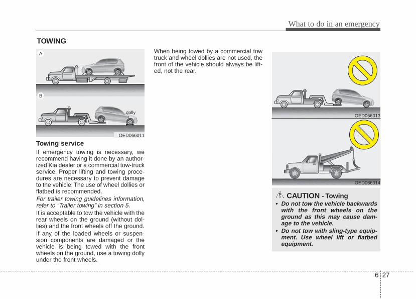
6 27
What to do in an emergency
TOWING
Towing serviceIf emergency towing is necessary, werecommend having it done by an author-ized Kia dealer or a commercial tow-truckservice. Proper lifting and towing proce-dures are necessary to prevent damageto the vehicle. The use of wheel dollies orflatbed is recommended.For trailer towing guidelines information,refer to “Trailer towing” in section 5.It is acceptable to tow the vehicle with therear wheels on the ground (without dol-lies) and the front wheels off the ground.If any of the loaded wheels or suspen-sion components are damaged or thevehicle is being towed with the frontwheels on the ground, use a towing dollyunder the front wheels.
When being towed by a commercial towtruck and wheel dollies are not used, thefront of the vehicle should always be lift-ed, not the rear.
CAUTION - Towing• Do not tow the vehicle backwards
with the front wheels on theground as this may cause dam-age to the vehicle.
• Do not tow with sling-type equip-ment. Use wheel lift or flatbedequipment.
OED066011
A
B
dollyOED066013
OED066014

What to do in an emergency
286
When towing your vehicle in an emer-gency without wheel dollies :1. Set the ignition switch in the ACC posi-
tion.2. Place the transaxle shift lever in N
(Neutral).3. Release the parking brake.
Removable towing hook (front) (if equipped)1.Remove the towing hook from the tool
case.2.Remove the hole cover pressing the
lower part of the cover on the frontbumper.
3. Install the towing hook by turning itclockwise into the hole until it is fullysecured.
4.Remove the towing hook and installthe cover after use.
Emergency towingIf towing is necessary, we recommendyou to have it done by an authorizedKia dealer or a commercial tow truckservice.
CAUTION - Towing gear position
Always place the transaxle shiftlever in Neutral (N) when towingyour vehicle. Failure to place thetransaxle shift lever in N (Neutral)may cause internal damage to thetransaxle.
OUB061011
OUB061013
Front
RearOUB061012

6 29
What to do in an emergency
If towing service is not available in anemergency, your vehicle may be tem-porarily towed using a cable or chainsecured to the emergency towing hookunder the front (or rear) of the vehicle.Use extreme caution when towing thevehicle. A driver must be in the vehicle tosteer it and operate the brakes.Towing in this manner may be done onlyon hard-surfaced roads for a short dis-tance and at low speeds. Also, thewheels, axles, power train, steering andbrakes must all be in good condition.• Do not use the towing hooks to pull a
vehicle out of mud, sand or other con-ditions from which the vehicle cannotbe driven out under its own power.
• Avoid towing a vehicle heavier than thevehicle doing the towing.
• The drivers of both vehicles shouldcommunicate with each other frequent-ly.
• Attach a towing strap to the towinghook.
• Using a portion of the vehicle otherthan the tow hooks for towing maydamage the body of your vehicle.
• Use only a cable or chain specificallyintended for use in towing vehicles.Securely fasten the cable or chain tothe towing hook provided.
• Before emergency towing, check thatthe hook is not broken or damaged.
• Fasten the towing cable or chainsecurely to the hook.
• Do not jerk the hook. Apply it steadilywith even force.
• To avoid damaging the hook, do notpull from the side or at a vertical angle.Always pull straight ahead.
• Use a towing strap less than 5 m (16 feet) long. Attach a white or redcloth (about 30 cm (12 inches) wide) inthe middle of the strap for easy visibili-ty.
• Drive carefully so that the towing strapis not loosened during towing.
OED066029
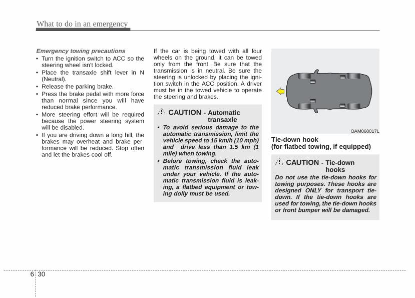
What to do in an emergency
306
Emergency towing precautions• Turn the ignition switch to ACC so the
steering wheel isn’t locked.• Place the transaxle shift lever in N
(Neutral).• Release the parking brake.• Press the brake pedal with more force
than normal since you will havereduced brake performance.
• More steering effort will be requiredbecause the power steering systemwill be disabled.
• If you are driving down a long hill, thebrakes may overheat and brake per-formance will be reduced. Stop oftenand let the brakes cool off.
If the car is being towed with all fourwheels on the ground, it can be towedonly from the front. Be sure that thetransmission is in neutral. Be sure thesteering is unlocked by placing the igni-tion switch in the ACC position. A drivermust be in the towed vehicle to operatethe steering and brakes.
Tie-down hook (for flatbed towing, if equipped)
CAUTION - Automatictransaxle
• To avoid serious damage to theautomatic transmission, limit thevehicle speed to 15 km/h (10 mph)and drive less than 1.5 km (1mile) when towing.
• Before towing, check the auto-matic transmission fluid leakunder your vehicle. If the auto-matic transmission fluid is leak-ing, a flatbed equipment or tow-ing dolly must be used.
CAUTION - Tie-downhooks
Do not use the tie-down hooks fortowing purposes. These hooks aredesigned ONLY for transport tie-down. If the tie-down hooks areused for towing, the tie-down hooksor front bumper will be damaged.
OAM060017L

7
Engine compartment / 7-2Maintenance services / 7-3Owner maintenance / 7-5Scheduled maintenance service / 7-7Explanation of scheduled maintenance items / 7-22Engine oil / 7-25Engine coolant / 7-26Brake/clutch fluid / 7-29Automatic transaxle fluid / 7-30Washer fluid / 7-30Parking brake / 7-31Air cleaner / 7-31Climate control air filter / 7-32Wiper blades / 7-32Battery / 7-34Tires and wheels / 7-37
Fuses / 7-50Appearance care / 7-60Emission control system / 7-66
Maintenance

Maintenance
27
ENGINE COMPARTMENT
1. Engine coolant reservoir
2. Engine oil filler cap
3. Brake/clutch fluid reservoir
4. Air cleaner
5. Fuse box
6. Positive battery terminal
7. Negative battery terminal
8. Windshield washer fluid reservoir
9. Radiator cap
10. Engine oil dipstick
OUB071103N
* The actual engine room in the vehicle may differ from the illustration.

7 3
Maintenance
MAINTENANCE SERVICESYou should exercise the utmost care toprevent damage to your vehicle andinjury to yourself whenever performingany maintenance or inspection proce-dures.Should you have any doubts concerningthe inspection or servicing of your vehi-cle, we strongly recommend that youhave an authorized Kia dealer performthis work.An authorized Kia dealer has factory-trained technicians and genuine Kiaparts to service your vehicle properly. Forexpert advice and quality service, see anauthorized Kia dealer.Inadequate, incomplete or insufficientservicing may result in operational prob-lems with your vehicle that could lead tovehicle damage, an accident, or person-al injury.
Owner’s responsibility
✽✽ NOTICEMaintenance Service and RecordRetention are the owner's responsibility.
You should retain documents that showproper maintenance has been performedon your vehicle in accordance with thescheduled maintenance service chartsshown on the following pages. You needthis information to establish your compli-ance with the servicing and maintenancerequirements of your vehicle warranties.Detailed warranty information is providedin your Warranty & Consumer Informationmanual.
Repairs and adjustments required as aresult of improper maintenance or a lackof required maintenance are not covered.We recommend you have your vehiclemaintained and repaired by an author-ized Kia dealer. An authorized Kia dealermeets Kia’s high service quality stan-dards and receives technical supportfrom Kia in order to provide you with ahigh level of service satisfaction.

Maintenance
47
Owner maintenance precautions Improper or incomplete service mayresult in problems. This section givesinstructions only for the maintenanceitems that are easy to perform.As explained earlier in this section, sev-eral procedures can be done only by anauthorized Kia dealer with special tools.
✽✽ NOTICEImproper owner maintenance duringthe warranty period may affect warran-ty coverage. For details, read the sepa-rate Warranty & Consumer Informationmanual provided with the vehicle. Ifyou're unsure about any servicing ormaintenance procedure, have it done byan authorized Kia dealer.
WARNING - Maintenancework
Do not wear jewelry or loose cloth-ing while working under the hoodof your vehicle with the engine run-ning. These can become entangledin moving parts, if you must run theengine while working under thehood, make certain that youremove all jewelry (especially rings,bracelets, watches, and necklaces)and all neckties, scarves, and simi-lar loose clothing before gettingnear the engine or cooling fans.

7 5
Maintenance
OWNER MAINTENANCE The following lists are vehicle checks andinspections that should be performed bythe owner or an authorized Kia dealer atthe frequencies indicated to help ensuresafe, dependable operation of your vehi-cle.Any adverse conditions should bebrought to the attention of your dealer assoon as possible.These Owner Maintenance Checks aregenerally not covered by warranties andyou may be charged for labor, parts andlubricants used.
Owner maintenance schedule When you stop for fuel:• Check the engine oil level.• Check the coolant level in coolant
reservoir.• Check the windshield washer fluid
level.• Look for low or under-inflated tires.
While operating your vehicle:• Note any changes in the sound of the
exhaust or any smell of exhaust fumesin the vehicle.
• Check for vibrations in the steeringwheel. Notice any increased steeringeffort or looseness in the steeringwheel, or change in its straight-aheadposition.
• Notice if your vehicle constantly turnsslightly or “pulls” to one side when trav-eling on smooth, level road.
• When stopping, listen and check forunusual sounds, pulling to one side,increased brake pedal travel or “hard-to-push” brake pedal.
• If any slipping or changes in the oper-ation of your transaxle occurs, checkthe transaxle fluid level.
• Check the automatic transaxle P (Park)function.
• Check the parking brake.• Check for fluid leaks under your vehicle
(water dripping from the air condition-ing system during or after use is nor-mal).
WARNING - Hot coolantBe careful when checking yourengine coolant level when theengine is hot. Scalding hot coolantand steam may blow out underpressure.

Maintenance
67
At least monthly:• Check the coolant level in the engine
coolant reservoir.• Check the operation of all exterior
lights, including the stoplights, turn sig-nals and hazard warning flashers.
• Check the inflation pressures of alltires including the spare.
At least twice a year (i.e., every Spring and Fall) :• Check the radiator, heater and air con-
ditioning hoses for leaks or damage.• Check the windshield washer spray
and wiper operation. Clean the wiperblades with clean cloth dampened withwasher fluid.
• Check the headlight alignment.• Check the muffler, exhaust pipes,
shields and clamps.• Check the lap/shoulder belts for wear
and function.• Check for worn tires and loose wheel
lug nuts.
At least once a year :• Clean the body and door drain holes.• Lubricate the door hinges and checks,
and hood hinges.• Lubricate the door and hood locks and
latches.• Lubricate the door rubber weather-
strips.• Check the air conditioning system.• Check the power steering fluid level.• Inspect and lubricate automatic
transaxle linkage and controls.• Clean the battery and terminals.• Check the brake/clutch fluid level.

7 7
Maintenance
SCHEDULED MAINTENANCE SERVICE Follow the Normal Maintenance Scheduleif the vehicle is usually operated wherenone of the following conditions apply. Ifany of the following conditions apply, fol-low the Maintenance Under SevereUsage Conditions.• Repeated short distance driving.• Driving in dusty conditions or sandy
areas.• Extensive use of brakes.• Driving in areas where salt or other
corrosive materials are being used.• Driving on rough or muddy roads.• Driving in mountainous areas.• Extended periods of idling or low
speed operation.• Driving for a prolonged period in cold
temperatures and/or extremely humidclimates.
• More than 50% driving in heavy citytraffic during hot weather above 32°C(90°F).
If your vehicle is operated under theabove conditions, you should inspect,replace or refill more frequently than thefollowing Normal Maintenance Schedule.After 120 months or 240,000 km(150,000 miles) continue to follow theprescribed maintenance intervals.
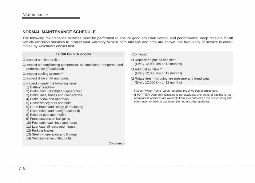
Maintenance
87
NORMAL MAINTENANCE SCHEDULEThe following maintenance services must be performed to ensure good emission control and performance. Keep receipts for allvehicle emission services to protect your warranty. Where both mileage and time are shown, the frequency of service is deter-mined by whichever occurs first.
12,000 km or 6 months
❑ Inspect air cleaner filter
❑ Inspect air conditioning compressor, air conditioner refrigerant andperformance (if equipped)
❑ Inspect cooling system *1
❑ Inspect drive shaft and boots
❑ Inspect visually the following items.1) Battery condition2) Brake fluid / clutch(if equipped) fluid3) Brake lines, hoses and connections4) Brake pedal and operation5) Chassis/body nuts and bolts6) Drum brake and linings (if equipped)7) Disc brakes and pads(if equipped)8) Exhaust pipe and muffler9) Front suspension ball joints10) Fuel tank, cap, lines and hoses11) Lubricate all locks and hinges12) Parking brakes13) Steering operation and linkage14) Suspension mounting bolts
(Continued)
(Continued)
❑ Replace engine oil and filter(Every 12,000 km or 12 months)
❑ Add fuel additive *A
(Every 12,000 km or 12 months)
❑ Rotate tires - including tire pressure and tread wear(Every 12,000 km or 12 months)
*1 lnspect "Water Pump" when replacing the drive belt or timing belt.*A If TOP TIER Detergent Gasoline is not available, one bottle of additive is rec-
ommended. Additives are available from your authorized Kia dealer along withinformation on how to use them. Do not mix other additives.
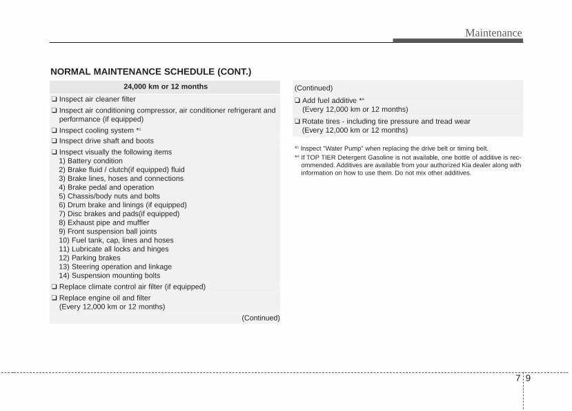
7 9
Maintenance
*1 lnspect "Water Pump" when replacing the drive belt or timing belt.*A If TOP TIER Detergent Gasoline is not available, one bottle of additive is rec-
ommended. Additives are available from your authorized Kia dealer along withinformation on how to use them. Do not mix other additives.
NORMAL MAINTENANCE SCHEDULE (CONT.)
24,000 km or 12 months
❑ Inspect air cleaner filter
❑ Inspect air conditioning compressor, air conditioner refrigerant andperformance (if equipped)
❑ Inspect cooling system *1
❑ Inspect drive shaft and boots
❑ Inspect visually the following items1) Battery condition2) Brake fluid / clutch(if equipped) fluid3) Brake lines, hoses and connections4) Brake pedal and operation5) Chassis/body nuts and bolts6) Drum brake and linings (if equipped)7) Disc brakes and pads(if equipped)8) Exhaust pipe and muffler9) Front suspension ball joints10) Fuel tank, cap, lines and hoses11) Lubricate all locks and hinges12) Parking brakes13) Steering operation and linkage14) Suspension mounting bolts
❑ Replace climate control air filter (if equipped)
❑ Replace engine oil and filter(Every 12,000 km or 12 months)
(Continued)
(Continued)
❑ Add fuel additive *A
(Every 12,000 km or 12 months)
❑ Rotate tires - including tire pressure and tread wear(Every 12,000 km or 12 months)

Maintenance
107
NORMAL MAINTENANCE SCHEDULE (CONT.)
48,000 km or 24 months
❑ Inspect air conditioning compressor, air conditioner refrigerant andperformance (if equipped)
❑ Inspect cooling system *1
❑ Inspect drive shaft and boots❑ Inspect fuel filter *2
❑ Inspect fuel line, hoses and connection❑ Inspect fuel tank air filter *2
❑ Inspect manual transaxle fluid (if equipped)(Every 60,000 km or 48 months)
❑ Inspect vapor hose and fuel filler cap
❑ Inspect visually the following items1) Battery condition2) Brake fluid / clutch (if equipped) fluid3) Brake lines, hoses and connections4) Brake pedal and operation5) Chassis/body nuts and bolts6) Drum brake and linings (if equipped)7) Disc brakes and pads (if equipped)8) Exhaust pipe and muffler9) Front suspension ball joints10) Fuel tank, cap, lines and hoses11) Lubricate all locks and hinges12) Parking brakes13) Steering operation and linkage14) Suspension mounting bolts
❑ Replace air cleaner filter(Continued)
(Continued)
❑ Replace climate control air filter (if equipped)❑ Replace engine oil and filter
(Every 12,000 km or 12 months)
❑ Add fuel additive *A
(Every 12,000 km or 12 months)
❑ Rotate tires - including tire pressure and tread wear(Every 12,000 km or 12 months)
*1 lnspect "Water Pump" when replacing the drive belt or timing belt.*2 Fuel filter & Fuel tank air filter are considered to be maintenance free but peri-
odic inspection is recommended for this maintenance schedule depends onfuel quality. If there are some important safety matters like fuel flow restriction,surging, loss of power, hard starting problem etc, replace the fuel filter imme-diately regardless of maintenance schedule and consult an authorized Kiadealer for details.
*A If TOP TIER Detergent Gasoline is not available, one bottle of additive is rec-ommended. Additives are available from your authorized Kia dealer along withinformation on how to use them. Do not mix other additives.

7 11
Maintenance
(Continued)
❑ Replace climate control air filter (if equipped)
❑ Replace engine oil and filter(Every 12,000 km or 12 months)
❑ Add fuel additive *A (Every 12,000 km or 12 months)
❑ Rotate tires - including tire pressure and tread wear(Every 12,000 km or 12 months)
72,000 km or 36 months
❑ Inspect air cleaner filter
❑ Inspect air conditioning compressor, air conditioner refrigerant andperformance (if equipped)
❑ Inspect cooling system *1
❑ Inspect drive shaft and boots
❑ Inspect visually the following items1) Battery condition2) Brake fluid / clutch (if equipped) fluid3) Brake lines, hoses and connections4) Brake pedal and operation5) Chassis/body nuts and bolts6) Drum brake and linings (if equipped)7) Disc brakes and pads (if equipped)8) Exhaust pipe and muffler9) Front suspension ball joints10) Fuel tank, cap, lines and hoses11) Lubricate all locks and hinges12) Parking brakes13) Steering operation and linkage14) Suspension mounting bolts
(Continued)
*1 lnspect "Water Pump" when replacing the drive belt or timing belt.*A If TOP TIER Detergent Gasoline is not available, one bottle of additive is rec-
ommended. Additives are available from your authorized Kia dealer along withinformation on how to use them. Do not mix other additives.
NORMAL MAINTENANCE SCHEDULE (CONT.)

Maintenance
127
NORMAL MAINTENANCE SCHEDULE (CONT.)
*1 lnspect "Water Pump" when replacing the drive belt or timing belt.*2 Fuel filter & Fuel tank air filter are considered to be maintenance free but peri-
odic inspection is recommended for this maintenance schedule depends onfuel quality. If there are some important safety matters like fuel flow restriction,surging, loss of power, hard starting problem etc, replace the fuel filter imme-diately regardless of maintenance schedule and consult an authorized Kiadealer for details.
*3 Inspect for excessive tappet noise and/or engine vibration and adjust if nec-essary.
*4 The drive belt should be replaced when cracks occur or tension is reducedexcessively.
*A If TOP TIER Detergent Gasoline is not available, one bottle of additive is rec-ommended. Additives are available from your authorized Kia dealer along withinformation on how to use them. Do not mix other additives.
96,000 km or 48 months
❑ Inspect air conditioning compressor, air conditioner refrigerant andperformance (if equipped)
❑ Inspect cooling system *1
❑ Inspect drive belt *4
(First, 96,000 km or 72 months after every 24,000 km or 24 months)
❑ Inspect drive shaft and boots❑ Inspect fuel filter *2
❑ Inspect fuel line, hoses and connection❑ Inspect fuel tank air filter *2
❑ Inspect valve clearance *3
❑ Inspect vapor hose and fuel filler cap
❑ Inspect visually the following items1) Battery condition2) Brake fluid / clutch (if equipped) fluid3) Brake lines, hoses and connections4) Brake pedal and operation5) Chassis/body nuts and bolts6) Drum brake and linings (if equipped)7) Disc brakes and pads (if equipped)
(Continued)
(Continued)
8) Exhaust pipe and muffler9) Front suspension ball joints10) Fuel tank, cap, lines and hoses11) Lubricate all locks and hinges12) Parking brakes13) Steering operation and linkage14) Suspension mounting bolts
❑ Replace air cleaner filter❑ Replace climate control air filter (if equipped)
❑ Replace engine oil and filter(Every 12,000 km or 12 months)
❑ Add fuel additive *A
(Every 12,000 km or 12 months)
❑ Rotate tires - including tire pressure and tread wear(Every 12,000 km or 12 months)

7 13
Maintenance
NORMAL MAINTENANCE SCHEDULE (CONT.)
120,000 km or 60 months
❑ Inspect air cleaner filter
❑ Inspect air conditioning compressor, air conditioner refrigerant andperformance (if equipped)
❑ Inspect cooling system *1
❑ Inspect drive belt *4
(First 96,000 km or 72 months after every 24,000 km or 24 months)
❑ Inspect drive shaft and boots
❑ Inspect manual transaxle fluid (if equipped)(Every 60,000 km or 48 months)
❑ Inspect visually the following items1) Battery condition2) Brake fluid / clutch (if equipped) fluid3) Brake lines, hoses and connections4) Brake pedal and operation5) Chassis/body nuts and bolts6) Drum brake and linings (if equipped)7) Disc brakes and pads (if equipped)
(Continued)
*1 lnspect "Water Pump" when replacing the drive belt or timing belt.*4 The drive belt should be replaced when cracks occur or tension is reduced
excessively.*A If TOP TIER Detergent Gasoline is not available, one bottle of additive is rec-
ommended. Additives are available from your authorized Kia dealer along withinformation on how to use them. Do not mix other additives.
(Continued)
8) Exhaust pipe and muffler9) Front suspension ball joints10) Fuel tank, cap, lines and hoses11) Lubricate all locks and hinges12) Parking brakes13) Steering operation and linkage14) Suspension mounting bolts
❑ Replace climate control air filter (if equipped)
❑ Replace engine oil and filter(Every 12,000 km or 12 months)
❑ Add fuel additive *A
(Every 12,000 km or 12 months)
❑ Rotate tires - including tire pressure and tread wear(Every 12,000 km or 12 months)

Maintenance
147
*1 lnspect "Water Pump" when replacing the drive belt or timing belt.*2 Fuel filter & Fuel tank air filter are considered to be maintenance free but peri-
odic inspection is recommended for this maintenance schedule depends onfuel quality. If there are some important safety matters like fuel flow restriction,surging, loss of power, hard starting problem etc, replace the fuel filter imme-diately regardless of maintenance schedule and consult an authorized Kiadealer for details.
*4 The drive belt should be replaced when cracks occur or tension is reducedexcessively.
*A If TOP TIER Detergent Gasoline is not available, one bottle of additive is rec-ommended. Additives are available from your authorized Kia dealer along withinformation on how to use them. Do not mix other additives.
NORMAL MAINTENANCE SCHEDULE (CONT.)
144,000 km or 72 months
❑ Inspect air conditioning compressor, air conditioner refrigerant andperformance (if equipped)
❑ Inspect cooling system *1
❑ Inspect drive belt *4
(First 96,000 km or 72 months after every 24,000 km or 24 months)
❑ Inspect drive shaft and boots ❑ Inspect fuel filter *2
❑ Inspect fuel line, hoses and connection❑ Inspect fuel tank air filter *2
❑ Inspect vapor hose and fuel filler cap
❑ Inspect visually the following items1) Battery condition2) Brake fluid / clutch (if equipped) fluid3) Brake lines, hoses and connections4) Brake pedal and operation5) Chassis/body nuts and bolts6) Drum brake and linings (if equipped)7) Disc brakes and pads (if equipped)8) Exhaust pipe and muffler9) Front suspension ball joints10) Fuel tank, cap, lines and hoses11) Lubricate all locks and hinges12) Parking brakes13) Steering operation and linkage14) Suspension mounting bolts
(Continued)
(Continued)
❑ Replace air cleaner filter❑ Replace climate control air filter (if equipped)
❑ Replace engine oil and filter(Every 12,000 km or 12 months)
❑ Add fuel additive *A
(Every 12,000 km or 12 months)
❑ Rotate tires - including tire pressure and tread wear(Every 12,000 km or 12 months)

7 15
Maintenance
(Continued)
❑ Replace climate control air filter (if equipped)
❑ Replace engine oil and filter(Every 12,000 km or 12 months)
❑ Add fuel additive *A
(Every 12,000 km or 12 months)
❑ Replace spark plugs (iridium coated),(Every 150,000 km or 120 months)
❑ Rotate tires - including tire pressure and tread wear(Every 12,000 km or 12 months)
*1 lnspect "Water Pump" when replacing the drive belt or timing belt.*4 The drive belt should be replaced when cracks occur or tension is reduced
excessively.*A If TOP TIER Detergent Gasoline is not available, one bottle of additive is rec-
ommended. Additives are available from your authorized Kia dealer along withinformation on how to use them. Do not mix other additives.
NORMAL MAINTENANCE SCHEDULE (CONT.)
168,000 km or 84 months
❑ Inspect air cleaner filter
❑ Inspect air conditioning compressor, air conditioner refrigerant andperformance (if equipped)
❑ Inspect cooling system *1
❑ Inspect drive belt *4
(First 96,000 km or 72 months after every 24,000 km or 24 months)
❑ Inspect drive shaft and boots
❑ Inspect manual transaxle fluid (if equipped)(Every 60,000 km or 48 months)
❑ Inspect visually the following items1) Battery condition2) Brake fluid / clutch (if equipped) fluid3) Brake lines, hoses and connections4) Brake pedal and operation5) Chassis/body nuts and bolts6) Drum brake and linings (if equipped)7) Disc brakes and pads (if equipped)8) Exhaust pipe and muffler9) Front suspension ball joints10) Fuel tank, cap, lines and hoses11) Lubricate all locks and hinges12) Parking brakes13) Steering operation and linkage14) Suspension mounting bolts
(Continued)
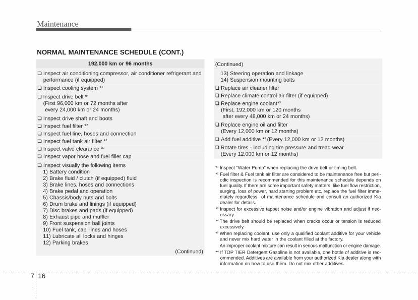
Maintenance
167
NORMAL MAINTENANCE SCHEDULE (CONT.)
192,000 km or 96 months
❑ Inspect air conditioning compressor, air conditioner refrigerant andperformance (if equipped)
❑ Inspect cooling system *1
❑ Inspect drive belt *4
(First 96,000 km or 72 months after every 24,000 km or 24 months)
❑ Inspect drive shaft and boots❑ Inspect fuel filter *2
❑ Inspect fuel line, hoses and connection❑ Inspect fuel tank air filter *2
❑ Inspect valve clearance *3
❑ Inspect vapor hose and fuel filler cap
❑ Inspect visually the following items1) Battery condition2) Brake fluid / clutch (if equipped) fluid3) Brake lines, hoses and connections4) Brake pedal and operation5) Chassis/body nuts and bolts6) Drum brake and linings (if equipped)7) Disc brakes and pads (if equipped)8) Exhaust pipe and muffler9) Front suspension ball joints10) Fuel tank, cap, lines and hoses11) Lubricate all locks and hinges12) Parking brakes
(Continued)
(Continued)
13) Steering operation and linkage14) Suspension mounting bolts
❑ Replace air cleaner filter❑ Replace climate control air filter (if equipped)
❑ Replace engine coolant*5
(First, 192,000 km or 120 months after every 48,000 km or 24 months)
❑ Replace engine oil and filter(Every 12,000 km or 12 months)
❑ Add fuel additive *A (Every 12,000 km or 12 months)
❑ Rotate tires - including tire pressure and tread wear(Every 12,000 km or 12 months)
*1 lnspect "Water Pump" when replacing the drive belt or timing belt.*2 Fuel filter & Fuel tank air filter are considered to be maintenance free but peri-
odic inspection is recommended for this maintenance schedule depends onfuel quality. If there are some important safety matters like fuel flow restriction,surging, loss of power, hard starting problem etc, replace the fuel filter imme-diately regardless of maintenance schedule and consult an authorized Kiadealer for details.
*3 Inspect for excessive tappet noise and/or engine vibration and adjust if nec-essary.
*4 The drive belt should be replaced when cracks occur or tension is reducedexcessively.
*5 When replacing coolant, use only a qualified coolant additive for your vehicleand never mix hard water in the coolant filled at the factory.An improper coolant mixture can result in serious malfunction or engine damage.
*A If TOP TIER Detergent Gasoline is not available, one bottle of additive is rec-ommended. Additives are available from your authorized Kia dealer along withinformation on how to use them. Do not mix other additives.

7 17
Maintenance
NORMAL MAINTENANCE SCHEDULE (CONT.)
216,000 km or 108 months
❑ Inspect air cleaner filter
❑ Inspect air conditioning compressor, air conditioner refrigerant andperformance (if equipped)
❑ Inspect cooling system *1
❑ Inspect drive belt *4
(First 96,000 km or 72 months after every 24,000 km or 24 months)
❑ Inspect drive shaft and boots
❑ Inspect visually the following items1) Battery condition2) Brake fluid / clutch (if equipped) fluid3) Brake lines, hoses and connections4) Brake pedal and operation5) Chassis/body nuts and bolts6) Drum brake and linings (if equipped)7) Disc brakes and pads (if equipped)8) Exhaust pipe and muffler9) Front suspension ball joints10) Fuel tank, cap, lines and hoses11) Lubricate all locks and hinges12) Parking brakes13) Steering operation and linkage14) Suspension mounting bolts
(Continued)
(Continued)
❑ Replace climate control air filter (if equipped)
❑ Replace engine oil and filter(Every 12,000 km or 12 months)
❑ Add fuel additive *A
(Every 12,000 km or 12 months)
❑ Rotate tires - including tire pressure and tread wear(Every 12,000 km or 12 months)
*1 lnspect "Water Pump" when replacing the drive belt or timing belt.*4 The drive belt should be replaced when cracks occur or tension is reduced
excessively.*A If TOP TIER Detergent Gasoline is not available, one bottle of additive is rec-
ommended. Additives are available from your authorized Kia dealer along withinformation on how to use them. Do not mix other additives.

Maintenance
187
240,000 km or 120 months
❑ Inspect air conditioning compressor, air conditioner refrigerant andperformance (if equipped)
❑ Inspect cooling system *1
❑ Inspect drive belt *4
(First 96,000 km or 72 months after every 24,000 km or 24 months)
❑ Inspect drive shaft and boots❑ Inspect fuel filter *2
❑ Inspect fuel line, hoses and connection❑ Inspect fuel tank air filter *2
❑ Inspect manual transaxle fluid (if equipped)(Every 60,000 km or 48 months)
❑ Inspect vapor hose and fuel filler cap
❑ Inspect visually the following items1) Battery condition2) Brake fluid / clutch (if equipped) fluid3) Brake lines, hoses and connections4) Brake pedal and operation5) Chassis/body nuts and bolts6) Drum brake and linings (if equipped)7) Disc brakes and pads (if equipped)8) Exhaust pipe and muffler9) Front suspension ball joints10) Fuel tank, cap, lines and hoses11) Lubricate all locks and hinges12) Parking brakes
(Continued)
(Continued)
13) Steering operation and linkage14) Suspension mounting bolts
❑ Replace air cleaner filter❑ Replace climate control air filter (if equipped)
❑ Replace engine coolant *5
(First 192,000 km or 120 months after every 48,000 km or 24 months)
❑ Replace engine oil and filter(Every 12,000 km or 12 months)
❑ Add fuel additive *A
(Every 12,000 km or 12 months)
❑ Rotate tires - including tire pressure and tread wear(Every 12,000 km or 12 months)
NORMAL MAINTENANCE SCHEDULE (CONT.)
*1 lnspect "Water Pump" when replacing the drive belt or timing belt.*2 Fuel filter & Fuel tank air filter are considered to be maintenance free but peri-
odic inspection is recommended for this maintenance schedule depends onfuel quality. If there are some important safety matters like fuel flow restriction,surging, loss of power, hard starting problem etc, replace the fuel filter imme-diately regardless of maintenance schedule and consult an authorized Kiadealer for details.
*4 The drive belt should be replaced when cracks occur or tension is reducedexcessively.
*5 When replacing coolant, use only a qualified coolant additive for your vehicleand never mix hard water in the coolant filled at the factory.An improper coolant mixture can result in serious malfunction or engine damage.
*A If TOP TIER Detergent Gasoline is not available, one bottle of additive is rec-ommended. Additives are available from your authorized Kia dealer along withinformation on how to use them. Do not mix other additives.
7 19
Maintenance
NORMAL MAINTENANCE SCHEDULE
No check, No service required
❑ Automatic transaxle fluid (if equipped)

Maintenance
207
MAINTENANCE UNDER SEVERE USAGE CONDITIONSThe following items must be serviced more frequently on cars normally used under severe driving conditions. Refer to the chartbelow for the appropriate maintenance intervals.R : Replace I : Inspect and, after inspection, clean, adjust, repair or replace if necessary
MAINTENANCE ITEMMAINTENANCE
OPERATIONMAINTENANCE INTERVALS
DRIVING CONDITION
ENGINE OIL AND FILTER R EVERY 6,000 km OR 6 MONTHSA, B, C, D, E, F,
G, H, I, K
AIR CLEANER FILTER R MORE FREQUENTLY C, E
SPARK PLUGS R MORE FREQUENTLY A, B, H, I, K
DISC BRAKE/ PADS, CALIPERS AND ROTORS
R MORE FREQUENTLY C, D, G, H
REAR BRAKE DRUMS/ LININGS, PARKING BRAKE
R MORE FREQUENTLY C, D, G, H
STEERING GEAR BOX, LINKAGE & BOOTS/LOWER ARM BALL JOINT, UPPER ARM BSALL JOINT
I MORE FREQUENTLY C, D, E, F, G, H, I
DRIVE SHAFTS AND BOOTS I EVERY 12,000 km OR 6 MONTHS C, D, E, F, G, H, I
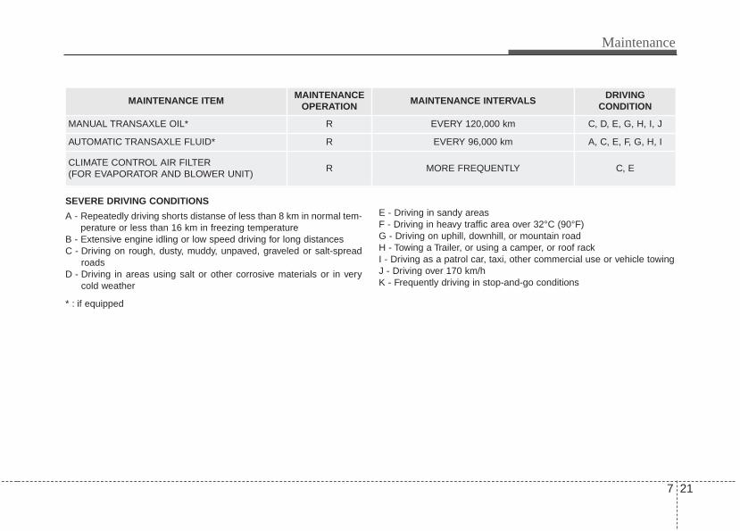
7 21
Maintenance
MAINTENANCE ITEMMAINTENANCE
OPERATIONMAINTENANCE INTERVALS
DRIVING CONDITION
MANUAL TRANSAXLE OIL* R EVERY 120,000 km C, D, E, G, H, I, J
AUTOMATIC TRANSAXLE FLUID* R EVERY 96,000 km A, C, E, F, G, H, I
CLIMATE CONTROL AIR FILTER (FOR EVAPORATOR AND BLOWER UNIT)
R MORE FREQUENTLY C, E
SEVERE DRIVING CONDITIONS
A - Repeatedly driving shorts distanse of less than 8 km in normal tem-perature or less than 16 km in freezing temperature
B - Extensive engine idling or low speed driving for long distancesC - Driving on rough, dusty, muddy, unpaved, graveled or salt-spread
roadsD - Driving in areas using salt or other corrosive materials or in very
cold weather
E - Driving in sandy areasF - Driving in heavy traffic area over 32°C (90°F)G - Driving on uphill, downhill, or mountain roadH - Towing a Trailer, or using a camper, or roof rackI - Driving as a patrol car, taxi, other commercial use or vehicle towingJ - Driving over 170 km/hK - Frequently driving in stop-and-go conditions
* : if equipped

Maintenance
227
EXPLANATION OF SCHEDULED MAINTENANCE ITEMSEngine oil and filterThe engine oil and filter should bechanged at the intervals specified in themaintenance schedule. If the vehicle isbeing driven in severe conditions, morefrequent oil and filter changes arerequired.
Drive beltsInspect all drive belts for evidence ofcuts, cracks, excessive wear or oil satu-ration and replace if necessary. Drivebelts should be checked periodically forproper tension and adjusted as neces-sary.
Fuel filterA clogged filter can limit the speed atwhich the vehicle may be driven, damagethe emission system and cause multipleissues such as hard starting. If an exces-sive amount of foreign matter accumu-lates in the fuel tank, the filter mayrequire replacement more frequently.After installing a new filter, run the enginefor several minutes, and check for leaksat the connections. Fuel filters should beinstalled by an authorized Kia dealer.
Fuel lines, fuel hoses and con-nectionsCheck the fuel lines, fuel hoses and con-nections for leakage and damage. Havean authorized Kia dealer replace anydamaged or leaking parts immediately.
Vapor hose and fuel filler capThe vapor hose and fuel filler cap shouldbe inspected at those intervals specifiedin the maintenance schedule. Make surethat a new vapor hose or fuel filler cap iscorrectly replaced.
Vacuum crankcase ventilationhoses (if equipped)Inspect the surface of hoses for evidenceof heat and/or mechanical damage. Hardand brittle rubber, cracking, tears, cuts,abrasions, and excessive swelling indi-cate deterioration. Particular attentionshould be paid to examine those hosesurfaces nearest to high heat sources,such as the exhaust manifold.Inspect the hose routing to assure thatthe hoses do not come in contact withany heat source, sharp edges or movingcomponent which might cause heat dam-age or mechanical wear. Inspect all hoseconnections, such as clamps and cou-plings, to make sure they are secure, andthat no leaks are present. Hoses shouldbe replaced immediately if there is anyevidence of deterioration or damage.

7 23
Maintenance
Air cleaner filterA Genuine Kia air cleaner filter is recom-mended when the filter is replaced.
Spark plugs Make sure to install new spark plugs ofthe correct heat range.
Valve clearance (if equipped)Inspect for excessive valve noise and/orengine vibration and adjust if necessary.An authorized Kia dealer should performthe operation.
Cooling systemCheck the cooling system components,such as the radiator, coolant reservoir,hoses and connections for leakage anddamage. Replace any damaged parts.
CoolantThe coolant should be changed at theintervals specified in the maintenanceschedule.
Manual transaxle fluid (if equipped)Inspect the manual transaxle fluidaccording to the maintenance schedule.
Automatic transaxle fluid (if equipped)Automatic transaxle fluid should not bechecked under normal usage conditions.But in severe conditions, the fluid shouldbe changed at an authorized Kia dealerin accordance to the scheduled mainte-nance at the beginning of this chapter.
✽✽ NOTICEAutomatic transaxle fluid color is basi-cally red. As the vehicle is driven, the automatictransaxle fluid will begin to look darker.This is a normal condition and youshould not judge the need to replace thefluid based upon the changed color.
Brake hoses and linesVisually check for proper installation,chafing, cracks, deterioration and anyleakage. Replace any deteriorated ordamaged parts immediately.
Brake/Clutch (if equipped) fluid Check the brake fluid level in the brakefluid reservoir. The level should bebetween “MIN” and “MAX” marks on theside of the reservoir. Use only hydraulicbrake fluid conforming to DOT 3 or DOT4 specification.
Parking brakeInspect the parking brake system includ-ing the parking brake lever and cables.
CAUTION - Specified fluidThe use of a non-specified fluidcould result in transaxle malfunc-tion and failure.Use only specified automatictransaxle fluid. (Refer to“Recommended lubricants andcapacities” in section 8.)
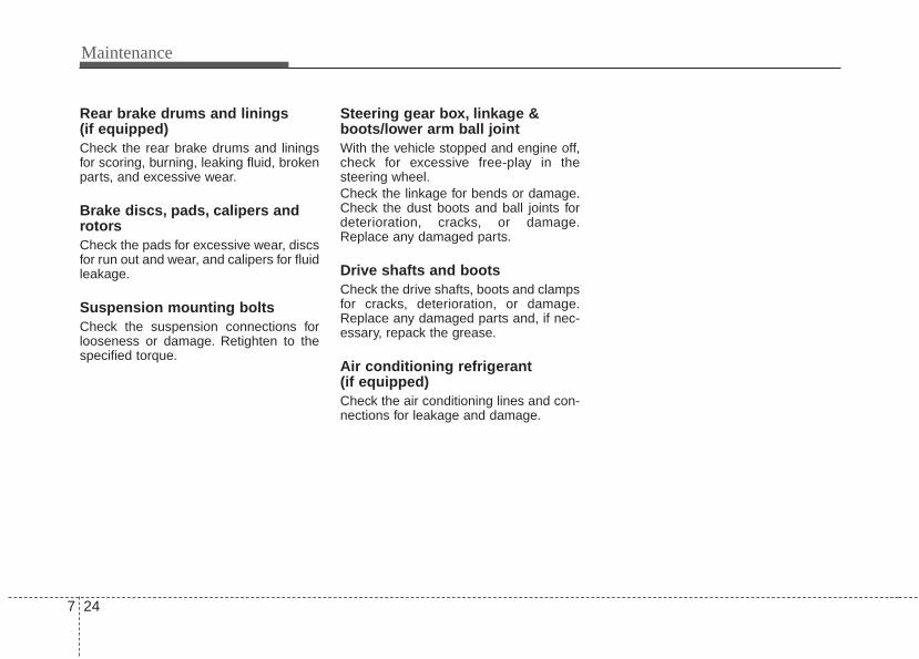
Maintenance
247
Rear brake drums and linings(if equipped)Check the rear brake drums and liningsfor scoring, burning, leaking fluid, brokenparts, and excessive wear.
Brake discs, pads, calipers androtorsCheck the pads for excessive wear, discsfor run out and wear, and calipers for fluidleakage.
Suspension mounting boltsCheck the suspension connections forlooseness or damage. Retighten to thespecified torque.
Steering gear box, linkage &boots/lower arm ball jointWith the vehicle stopped and engine off,check for excessive free-play in thesteering wheel.Check the linkage for bends or damage.Check the dust boots and ball joints fordeterioration, cracks, or damage.Replace any damaged parts.
Drive shafts and bootsCheck the drive shafts, boots and clampsfor cracks, deterioration, or damage.Replace any damaged parts and, if nec-essary, repack the grease.
Air conditioning refrigerant (if equipped)Check the air conditioning lines and con-nections for leakage and damage.

7 25
Maintenance
ENGINE OIL
Checking the engine oil level 1. Be sure the vehicle is on level ground.2. Start the engine and allow it to reach
normal operating temperature.3. Turn the engine off and wait for a few
minutes (about 5 minutes) for the oil toreturn to the oil pan.
4. Pull the dipstick out, wipe it clean, andreinsert it fully.
5. Pull the dipstick out again and checkthe level. The level should be betweenF and L.
If it is near or at L, add enough oil to bringthe level to F. Do not overfill.
Use a funnel to help prevent oil frombeing spilled on engine components.
Use only the specified engine oil. (Referto “Recommended lubricants and capaci-ties” in section 8.)
WARNING - Radiator hoseBe very careful not to touch theradiator hose when checking oradding the engine oil as it may behot enough to burn you.
CAUTION - Replace engineoil
Do not overfill with engine oil.Engine damage may result.
OAM072001 OAM072003

Maintenance
267
ENGINE COOLANTChanging the engine oil and filterHave engine oil and filter changed by anauthorized Kia dealer according to theMaintenance Schedule at the beginningof this section.
The high-pressure cooling system has areservoir filled with year-round antifreezecoolant. The reservoir is filled at the fac-tory.Check the antifreeze protection andcoolant level at least once a year, at thebeginning of the winter season, andbefore traveling to a colder climate.
Checking the coolant level Check the condition and connections ofall cooling system hoses and heaterhoses. Replace any swollen or deterio-rated hoses.The coolant level should be filledbetween F (MAX) and L (MIN) marks onthe side of the coolant reservoir when theengine is cool.
WARNING - Cooling fanUse caution when work-ing near the blade of thecooling fan. The electricmotor (cooling fan) iscontrolled by engine
coolant temperature, refrigerantpressure and vehicle speed. It maysometimes operate even when theengine is not running.
OAM072005
WARNINGUsed engine oil may cause irrita-tion or cancer of the skin if left incontact with the skin for prolongedperiods of time. Used engine oilcontains chemicals that havecaused cancer in laboratory ani-mals. Always protect your skin bywashing your hands thoroughlywith soap and warm water as soonas possible after handling used oil.

7 27
Maintenance
If the coolant level is low, add enoughspecified coolant to provide protectionagainst freezing and corrosion. Bring thelevel to F (MAX), but do not overfill. If fre-quent coolant addition is required, see anauthorized Kia dealer for a cooling sys-tem inspection.
Recommended engine coolant• When adding coolant, use only deion-
ized water or soft water for your vehicleand never mix hard water in thecoolant filled at the factory. An improp-er coolant mixture can result in seriousmalfunction or engine damage.
• The engine in your vehicle has alu-minum engine parts and must be pro-tected by an ethylene-glycol-basedcoolant to prevent corrosion and freez-ing.
• DO NOT USE alcohol or methanolcoolant or mix them with the specifiedcoolant.
• Do not use a solution that containsmore than 60% antifreeze or less than35% antifreeze, which would reducethe effectiveness of the solution.
For mixture percentage, refer to the fol-lowing table.
-15°C (5°F) 35 65
-25°C (-13°F) 40 60
-35°C (-31°F) 50 50
-45°C (-49°F) 60 40
AmbientTemperature
Mixture Percentage (volume)
Antifreeze Water
WARNING Radiator cap
Do not remove the radiator capwhen the engine and radiator arehot. Scalding hot coolant andsteam may blow out under pres-sure.
OAM072006

Maintenance
287
Turn the engine off and wait until it coolsdown. Use care when removing the radi-ator cap. Wrap a thick towel around it,and turn it counterclockwise slowly to thefirst stop. Step back while the pressure isreleased from the cooling system. Whenyou are sure all the pressure has beenreleased, press down on the cap, using athick towel, and continue turning counter-clockwise to remove it.
Changing the coolantHave the coolant changed by an author-ized Kia dealer according to theMaintenance Schedule at the beginningof this section.Put a thick cloth or fabric around the radi-ator cap before refilling the coolant inorder to prevent the coolant from over-flowing into engine parts such as thealternator.
CAUTION - Removing radi-ator cap
Never attempt to removethe radiator cap whilethe engine is operatingor hot. Doing so mightlead to cooling systemand engine damage.

7 29
Maintenance
BRAKE/CLUTCH (IF EQUIPPED) FLUID
Checking the brake/clutch* fluidlevel Check the fluid level in the reservoir peri-odically. The fluid level should bebetween MAX and MIN marks on theside of the reservoir.Before removing the reservoir cap andadding brake/clutch* fluid, clean the areaaround the reservoir cap thoroughly toprevent brake/clutch* fluid contamina-tion.
* if equipped
If the level is low, add fluid to the MAXlevel. The level will fall with accumulatedmileage. This is a normal condition asso-ciated with the wear of the brake liningsand/or clutch disc (if equipped). If thefluid level is excessively low, have thebrake/clutch* system checked by anauthorized Kia dealer.
Use only the specified brake/clutch* fluid.(Refer to “Recommended lubricants andcapacities” in section 8.)
Never mix different types of fluid.
In the event the brake/clutch* systemrequires frequent additions of fluid, thevehicle should be inspected by anauthorized Kia dealer.
When changing and adding brake/clutch*fluid, handle it carefully. Do not let it comein contact with your eyes. If brake/clutch*fluid should come in contact with youreyes, immediately flush them with a largequantity of fresh tap water. Have youreyes examined by a doctor as soon aspossible.
Brake/clutch* fluid, which has beenexposed to open air for an extended timeshould never be used as its quality can-not be guaranteed. It should be disposedof properly.
CAUTION - Brake/clutchfluid
Do not allow brake/clutch* fluid tocontact the vehicle's body paint, aspaint damage will result.
CAUTION - Proper fluidOnly use brake/clutch fluid inbrake/clutch system. Smallamounts of improper fluids (suchas engine oil) can cause damage tothe brake/clutch system.
OUB071007

Maintenance
307
It is recommended that the automatictransaxle fluid should be checked by anauthorized Kia dealer.In severe conditions, the fluid should bechanged at an authorized Kia dealer inaccordance to the scheduled mainte-nance at the beginning of this chapter.
Checking the washer fluid level Check the fluid level in the washer fluidreservoir and add fluid if necessary. Plainwater may be used if washer fluid is notavailable. However, use washer solventwith antifreeze characteristics in cold cli-mates to prevent freezing.
WARNING - Windshieldfluid
Do not drink the windshield washerfluid.The windshield washer fluid ispoisonous to humans and animals.
WARNING - Flammablefluid
Do not allow the washer fluid tocome in contact with open flamesor sparks. The windshield washerfluid clan is flammable under cer-tain circumstances. This can resultin a fire.
WASHER FLUIDAUTOMATIC TRANSAXLEFLUID
OUB071009

7 31
Maintenance
PARKING BRAKE
Checking the parking brake Check the stroke of the parking brake bycounting the number of “clicks’’ heardwhile fully applying it from the releasedposition. Also, the parking brake aloneshould securely hold the vehicle on a fair-ly steep grade. If the stroke is more orless than specified, have the parkingbrake adjusted by an authorized Kiadealer.
Stroke : 6~8 “clicks’’ at a force of 20 kg (44 lbs, 196 N).
Filter replacement It must be replaced when necessary, andshould not be washed.You can clean the filter when inspectingthe air cleaner element.Clean the filter by using compressed air.
Replace the filter according to theMaintenance Schedule.If the vehicle is operated in extremelydusty or sandy areas, replace the ele-ment more often than the usual recom-mended intervals. (Refer to“Maintenance under severe usage condi-tions” in this section.)
AIR CLEANER
OUB051016 OUB071010
CAUTION - Air filter maintenance
• Do not drive with the air cleanerremoved; this will result in exces-sive engine wear.
• When removing the air cleaner fil-ter, be careful that dust or dirtdoes not enter the air intake, ordamage may result.
• Use a Kia genuine part. Use ofnongenuine part could damagethe air flow sensor.

Maintenance
327
Filter inspectionThe climate control air filter should bereplaced according to the MaintenanceSchedule. If the vehicle is operated inseverely air-polluted cities or on dustyrough roads for a long period, it shouldbe inspected more frequently andreplaced earlier. When you replace theclimate control air filter, replace it per-forming the following procedure, and becareful to avoid damaging other compo-nents.
Blade inspectionCommercial hot waxes applied by auto-matic car washes have been known tomake the windshield difficult to clean.
Contamination of either the windshield orthe wiper blades with foreign matter canreduce the effectiveness of the wind-shield wipers. Common sources of con-tamination are insects, tree sap, and hotwax treatments used by some commer-cial car washes. If the blades are not wip-ing properly, clean both the window andthe blades with a good cleaner or milddetergent, and rinse thoroughly withclean water.
CLIMATE CONTROL AIR FIL-TER (IF EQUIPPED)
WIPER BLADES
1JBA5122CAUTION - Wiper blades
To prevent damage to the wiperblades, do not use gasoline,kerosene, paint thinner, or othersolvents on or near them.

7 33
Maintenance
Blade replacement When the wipers no longer clean ade-quately, the blades may be worn orcracked, and require replacement.To prevent damage to the wiper arms orother components, do not attempt tomove the wipers manually.The use of a non-specified wiper bladecould result in wiper malfunction and fail-ure.
Front windshield wiper blade
1. Raise the wiper arm and turn the wiperblade assembly to expose the plasticlocking clip. 2. Compress the clip and slide the blade
assembly downward.3. Lift it off the arm.4. Install the blade assembly in the
reverse order of removal.
1LDA5023
CAUTIONDo not allow the wiper arm to fallagainst the windshield, since it maychip or crack the windshield.
1JBA7037
1JBA7038

Maintenance
347
Rear window wiper blade 1. Raise the wiper arm and pull out the
wiper blade assembly.
2. Install the new blade assembly byinserting the center part into the slot inthe wiper arm until it clicks into place.
3. Make sure the blade assembly isinstalled firmly by trying to pull it slight-ly.
To prevent damage to the wiper arms orother components, have an authorizedKia dealer replace the wiper blade.
For best battery service• Keep the battery securely mounted.• Keep the battery top clean and dry.• Keep the terminals and connections
clean, tight, and coated with petroleumjelly or terminal grease.
• Rinse any spilled electrolyte from thebattery immediately with a solution ofwater and baking soda.
• If the vehicle is not going to be used foran extended time, disconnect the bat-tery cables.
OED076040 OED076041
BATTERY
OUB071017

7 35
Maintenance
Always read the followinginstructions carefully when han-dling a battery.If any electrolyte gets into youreyes, flush your eyes with cleanwater for at least 15 minutes andget immediate medical attention.If electrolyte gets on your skin,thoroughly wash the contactedarea. If you feel pain or burningsensation, get medical attentionimmediately.An inappropriately disposed bat-tery can be harmful to the envi-ronment and human health.Dispose the battery according toyour local law(s) or regulation.The battery contains lead. Donot dispose of it after use.Please return the battery to anauthorized Kia dealer to be recy-cled.
When you don’t use the vehicle for a longtime in the low temperature area, sepa-rate the battery and keep it indoors.
WARNING - Risk of explosion
Keep Lit cigarettes and allother flames or sparksaway from the battery.The battery contains hydro-gen -- a highly combustiblegas, which will explode if itcomes in contact with aflame or spark.
WARNING - Sulfuric acidin batteries
Keep batteries out of thereach of children becausebatteries contain highlycorrosive SULFURIC ACIDand electrolytes. Do notallow battery acid to con-tact your skin, eyes, cloth-ing or paint finish.Wear eye protection whencharging or working near abattery. Always provideventilation when working inan enclosed space.
WARNING - Recharging battery
Never attempt to recharge the bat-tery when the battery cables areconnected.
WARNING - Risk of elec-trocution
Never touch the electrical ignitionsystem while the vehicle is run-ning. This system works with highvoltage which can "zap" you.

Maintenance
367
Battery recharging Your vehicle has a maintenance-free,calcium-based battery.• If the battery becomes discharged in a
short time (because, for example, theheadlights or interior lights were left onwhile the vehicle was not in use),recharge it by slow charging (trickle)for 10 hours.
• If the battery gradually dischargesbecause of high electric load while thevehicle is being used, recharge it at 20-30A for two hours.
When recharging the battery, observethe following precautions:• The battery must be removed from the
vehicle and placed in an area withgood ventilation.
• Watch the battery during charging, andstop or reduce the charging rate if thebattery cells begin gassing (boiling)violently or if the temperature of theelectrolyte of any cell exceeds 49°C(120°F).
• Wear eye protection when checkingthe battery during charging.
• Disconnect the battery charger in thefollowing order.1. Turn off the battery charger main
switch.2. Unhook the negative clamp from the
negative battery terminal.3. Unhook the positive clamp from the
positive battery terminal.• Before performing maintenance or
recharging the battery, turn off allaccessories and stop the engine.
• The negative battery cable must beremoved first and installed last whenthe battery is disconnected.
Reset itemsItems should be reset after the batteryhas been discharged or the battery hasbeen disconnected.• Auto down window (See section 4)• Sunroof (See section 4)• Trip computer (See section 4)• Climate control system
(See section 4)• Clock (See section 4)• Audio (See section 4)

7 37
Maintenance
TIRES AND WHEELS Tire care For proper maintenance, safety, andmaximum fuel economy, you mustalways maintain recommended tireinflation pressures and stay withinthe load limits and weight distributionrecommended for your vehicle.
Recommended cold tire inflationpressures All tire pressures (including thespare) should be checked when thetires are cold. “Cold Tires” means thevehicle has not been driven for atleast three hours or driven less than1.6 km (one mile).Recommended pressures must bemaintained for the best ride, top vehi-cle handling, and minimum tire wear.For recommended inflation pressurerefer to “Tire and wheels” in section8.
All specifications (sizes and pres-sures) can be found on a labelattached to the driver’s side centerpillar.
WARNING - Tire underin-flation
Inflate your tires consistent withthe instructions provided in thismanual. Severe underinflation(70 kPa (10 psi) or more) canlead to severe heat build-up,causing blowouts, tread separa-tion and other tire failures thatcan result in the loss of vehiclecontrol.This risk is much higheron hot days and when drivingfor long periods at high speeds.
OUB071018

Maintenance
387
• Underinflation also results inexcessive wear, poor handling andreduced fuel economy. Wheeldeformation also is possible. Keepyour tire pressures at the properlevels. If a tire frequently needsrefilling, have it checked by anauthorized Kia dealer.
• Overinflation produces a harshride, excessive wear at the centerof the tire tread, and a greater pos-sibility of damage from road haz-ards.
• Warm tires normally exceed rec-ommended cold tire pressures by28 to 41 kPa (4 to 6 psi). Do notrelease air from warm tires toadjust the pressure or the tires willbe underinflated.
• Be sure to reinstall the tire inflationvalve caps. Without the valve cap,dirt or moisture could get into thevalve core and cause air leakage. Ifa valve cap is missing, install anew one as soon as possible.
Always observe the following:• Check tire pressure when the tires
are cold. (After vehicle has beenparked for at least three hours orhasn't been driven more than 1.6km (one mile) since startup.)
• Check the pressure of your sparetire each time you check the pres-sure of other tires.
• Never overload your vehicle. Becareful not to overload a vehicleluggage rack if your vehicle isequipped with one.
Checking tire inflation pressureCheck your tires once a month ormore.Also, check the tire pressure of thespare tire.
How to checkUse a good quality guage to checktire pressure. You can not tell if yourtires are properly inflated simply bylooking at them. Radial tires maylook properly inflated even whenthey're underinflated.Check the tire's inflation pressurewhen the tires are cold. - "Cold"means your vehicle has been sittingfor at least three hours or driven nomore than 1.6 km (1 mile).

7 39
Maintenance
Remove the valve cap from the tirevalve stem. Press the tire guage firm-ly onto the valve to get a pressuremeasurement. If the cold tire inflationpressure matches the recommendedpressure on the tire and loadinginformation label, no further adjust-ment is necessary. If the pressure islow, add air until you reach the rec-ommended amount.If you overfill the tire, release air bypushing on the metal stem in thecenter of the tire valve. Recheck thetire pressure with the tire guage. Besure to put the valve caps back onthe valve stems. They help preventleaks by keeping out dirt and mois-ture.
• Inspect your tires frequently forproper inflation as well as wear anddamage. Always use a tire pres-sure gauge.
• Tires with too much or too littlepressure wear unevenly causingpoor handling, loss of vehicle con-trol, and sudden tire failure leadingto accidents, injuries, and evendeath. The recommended cold tirepressure for your vehicle can befound in this manual and on the tirelabel located on the driver's sidecenter pillar.
• Remember to check the pressureof your spare tire. Kia recommendsthat you check the spare everytime you check the pressure of theother tires on your vehicle.
Tire rotation To equalize tread wear, it is recom-mended that the tires be rotatedevery 12,000 km miles (7,500) orsooner if irregular wear develops.During rotation, check the tires forcorrect balance.When rotating tires, check for unevenwear and damage. Abnormal wear isusually caused by incorrect tire pres-sure, improper wheel alignment, out-of-balance wheels, severe braking orsevere cornering. Look for bumps orbulges in the tread or side of tire.Replace the tire if you find either ofthese conditions. Replace the tire iffabric or cord is visible. After rotation,be sure to bring the front and rear tirepressures to specification and checklug nut tightness.Refer to “Tire and wheels” in section8.

Maintenance
407
Disc brake pads should be inspectedfor wear whenever tires are rotated.
Rotate radial tires that have anasymmetric tread pattern only fromfront to rear and not from right to left.Do not use the compact spare tire fortire rotation.
Wheel alignment and tire balance The wheels on your vehicle werealigned and balanced carefully at thefactory to give you the longest tire lifeand best overall performance.In most cases, you will not need tohave your wheels aligned again.However, if you notice unusual tirewear or your vehicle pulling one wayor the other, the alignment may needto be reset.If you notice your vehicle vibratingwhen driving on a smooth road, yourwheels may need to be rebalanced.
WARNING - Mixing tiretypes
Do not mix bias ply and radialply tires under any circum-stances.This may cause unusu-al handling characteristics.
S2BLA790A
CBGQ0707A
Without a spare tire
Directional tires (if equipped)
CAUTION - Wheel weightImproper wheel weights candamage your vehicle's alu-minum wheels. Use onlyapproved wheel weights.

7 41
Maintenance
Tire replacementIf the tire is worn evenly, a tread wearindicator will appear as a solid bandacross the tread. This shows there isless than 1.6 mm (1/16 inch) of treadleft on the tire. Replace the tire whenthis happens.Do not wait for the band to appearacross the entire tread before replac-ing the tire.
The ABS works by comparing thespeed of the wheels. Tire size canaffect wheel speed. When replacingtires, all 4 tires must use the samesize originally supplied with the vehi-cle. Using tires of a different size cancause the ABS (Anti-lock BrakeSystem) and ESC (ElectronicStability Control) (if equipped) towork irregularly.
Compact spare tire replacement A compact spare tire has a shortertread life than a regular size tire.Replace it when you can see thetread wear indicator bars on the tire.The replacement compact spare tireshould be the same size and designtire as the one provided with yournew vehicle and should be mountedon the same compact spare tirewheel. The compact spare tire is notdesigned to be mounted on a regularsize wheel, and the compact sparetire wheel is not designed for mount-ing a regular size tire.
OEN076053
Tread wear indicator

Maintenance
427
Wheel replacement When replacing the metal wheels forany reason, make sure the newwheels are equivalent to the originalfactory units in diameter, rim widthand offset.A wheel that is not the correct sizemay adversely affect wheel andbearing life, braking and stoppingabilities, handling characteristics,ground clearance, body-to-tire clear-ance, snow chain clearance,speedometer and odometer calibra-tion, headlight aim and bumperheight.
Tire tractionTire traction can be reduced if youdrive on worn tires, tires that areimproperly inflated or on slipperyroad surfaces. Tires should bereplaced when tread wear indicatorsappear. Slow down whenever thereis rain, snow or ice on the road, toreduce the possibility of losing con-trol of the vehicle.
Tire maintenance In addition to proper inflation, correctwheel alignment helps to decreasetire wear. If you find a tire is wornunevenly, have your dealer check thewheel alignment.When you have new tires installed,make sure they are balanced. Thiswill increase vehicle ride comfort andtire life. Additionally, a tire shouldalways be rebalanced if it is removedfrom the wheel.
Tire sidewall labelingThis information identifies anddescribes the fundamental charac-teristics of the tire and also providesthe tire identification number (TIN)for safety standard certification. TheTIN can be used to identify the tire incase of a recall.
1. Manufacturer or brand nameManufacturer or Brand name isshown.
CAUTION - WheelWheels that do not meet Kia'sspecifications may fit poorlyand result in damage to thevehicle or unusual handling andpoor vehicle control.
I030B04JM
1
1
23
4
5,6
7

7 43
Maintenance
2. Tire size designation A tire’s sidewall is marked with a tiresize designation. You will need thisinformation when selecting replace-ment tires for your car. The followingexplains what the letters and num-bers in the tire size designationmean.Example tire size designation:(These numbers are provided as anexample only; your tire size designa-tor could vary depending on yourvehicle.)P205/55R16 89H
P - Applicable vehicle type (tiresmarked with the prefix “P’’ areintended for use on passengervehicles or light trucks; however,not all tires have this marking).
205 - Tire width in millimeters.55 - Aspect ratio. The tire’s section
height as a percentage of itswidth.
R - Tire construction code (Radial).16 - Rim diameter in inches.
89 - Load Index, a numerical codeassociated with the maximumload the tire can carry.
H - Speed Rating Symbol. See thespeed rating chart in this sectionfor additional information.
Wheel size designation Wheels are also marked with impor-tant information that you need if youever have to replace one. The follow-ing explains what the letters andnumbers in the wheel size designa-tion mean.
Example wheel size designation:6.0JX16
6.0 - Rim width in inches.J - Rim contour designation.16 - Rim diameter in inches.
Tire speed ratings The chart below lists many of the dif-ferent speed ratings currently beingused for passenger vehicles. Thespeed rating is part of the tire sizedesignation on the sidewall of thetire. This symbol corresponds to thattire's designed maximum safe oper-ating speed.
S 180 km/h (112 mph)T 190 km/h (118 mph)H 210 km/h (130 mph)V 240 km/h (149 mph)Z 240 km/h (Above 149 mph)
Maximum SpeedSpeedRatingSymbol

Maintenance
447
3. Checking tire life (TIN : TireIdentification Number)
Any tires that are over 6 years old,based on the manufacturing date,(including the spare tire) should bereplaced by new ones. You can findthe manufacturing date on the tiresidewall (possibly on the inside of thewheel), displaying the DOT Code.The DOT Code is a series of num-bers on a tire consisting of numbersand English letters. The manufactur-ing date is designated by the last fourdigits (characters) of the DOT code.
DOT : XXXX XXXX OOOOThe front part of the DOT means aplant code number, tire size andtread pattern and the last four num-bers indicate week and year manu-factured.For example:DOT XXXX XXXX 1611 representsthat the tire was produced in the 16thweek of 2011.
4. Tire ply composition and materialThe number of layers or plies of rub-ber-coated fabric in the tire. Tiremanufacturers also must indicate thematerials in the tire, which includesteel, nylon, polyester, and others.The letter "R" means radial ply con-struction; the letter "D" means diago-nal or bias ply construction; and theletter "B" means belted-bias ply con-struction.
5. Maximum permissible inflationpressure
This number is the greatest amountof air pressure that should be put inthe tire. Do not exceed the maximumpermissible inflation pressure. Referto the Tire and Loading Informationlabel for recommended inflationpressure.
6. Maximum load ratingThis number indicates the maximumload in kilograms and pounds thatcan be carried by the tire. Whenreplacing the tires on the vehicle,always use a tire that has the sameload rating as the factory installedtire.
WARNING - Tire ageReplace tires within the recom-mended time frame. Failure toreplace tires as recommendedcan result in sudden tire failure,which could lead to a loss ofcontrol and an accident.

7 45
Maintenance
7. Uniform tire quality grading Quality grades can be found whereapplicable on the tire sidewallbetween tread shoulder and maxi-mum section width.For example:TREADWEAR 440 TRACTION A TEMPERATURE A
Tread wearThe tread wear grade is a compara-tive rating based on the wear rate ofthe tire when tested under controlledconditions on a specified govern-ment test course. For example, a tiregraded 150 would wear one-and-a-half times (1½) as well on the gov-ernment course as a tire graded 100.The relative performance of tiresdepends upon the actual conditionsof their use, however, and maydepart significantly from the normdue to variations in driving habits,service practices and differences inroad characteristics and climate.
Tires degrade over time, even whenthey are not being used. Regardlessof the remaining tread, we recom-mend that tires be replaced afterapproximately six (6) years of nor-mal service. Heat caused by hot cli-mates or frequent high loading con-ditions can accelerate the agingprocess.These grades are molded on theside-walls of passenger vehicle tires.The tires available as standard oroptional equipment on your vehiclesmay vary with respect to grade.
Traction - AA, A, B & C The traction grades, from highest tolowest, are AA, A, B and C. Thosegrades represent the tires ability tostop on wet pavement as measuredunder controlled conditions on spec-ified government test surfaces ofasphalt and concrete. A tire markedC may have poor traction perform-ance.The traction grade assigned to thistire is based on straight-ahead brak-ing traction tests, and does notinclude acceleration, cornering,hydroplaning, or peak traction char-acteristics.

Maintenance
467
Temperature -A, B & C The temperature grades are A (thehighest), B and C representing thetire’s resistance to the generation ofheat and its ability to dissipate heatwhen tested under controlled condi-tions on a specified indoor laboratorytest wheel.Sustained high temperature cancause the material of the tire todegenerate and reduce tire life, andexcessive temperature can lead tosudden tire failure. Grades B and Arepresent higher levels of perform-ance on the laboratory test wheelthan the minimum required by law.
Tire terminology and definitionsAir Pressure: The amount of airinside the tire pressing outward onthe tire. Air pressure is expressed inkilopascal (kPa) or pounds persquare inch (psi).Accessory Weight: This means thecombined weight of optional acces-sories. Some examples of optionalaccessories are, automatictransaxle, power seats, and air con-ditioning.Aspect Ratio: The relationship of atire's height to its width.Belt: A rubber coated layer of cordsthat is located between the plies andthe tread. Cords may be made fromsteel or other reinforcing materials.Bead: The tire bead contains steelwires wrapped by steel cords thathold the tire onto the rim.Bias Ply Tire: A pneumatic tire inwhich the plies are laid at alternateangles less than 90 degrees to thecenterline of the tread.
Cold Tire Pressure: The amount ofair pressure in a tire, measured inkilopascals (kPa) or pounds persquare inch (psi) before a tire hasbuilt up heat from driving.Curb Weight: This means the weightof a motor vehicle with standard andoptional equipment including themaximum capacity of fuel, oil andcoolant, but without passengers andcargo.DOT Markings: The DOT codeincludes the Tire IdentificationNumber (TIN), an alphanumeric des-ignator which can also identify thetire manufacturer, production plant,brand and date of production.GVWR: Gross Vehicle Weight RatingGAWR FRT: Gross Axle WeightRating for the Front Axle.GAWR RR: Gross Axle WeightRating for the Rear axle.
7 47
Maintenance
Intended Outboard Sidewall: Theside of an asymmetrical tire, thatmust always face outward whenmounted on a vehicle.Kilopascal (kPa): The metric unit forair pressure.Load Index: An assigned numberranging from 1 to 279 that corre-sponds to the load carrying capacityof a tire.Maximum Inflation Pressure: Themaximum air pressure to which acold tire may be inflated. The maxi-mum air pressure is molded onto thesidewall.Maximum Load Rating: The loadrating for a tire at the maximum per-missible inflation pressure for thattire.Maximum Loaded Vehicle Weight:The sum of curb weight; accessoryweight; vehicle capacity weight; andproduction options weight.Normal Occupant Weight: Thenumber of occupants a vehicle isdesigned to seat multiplied by 68 kg(150 pounds).
Occupant Distribution: Designatedseating positions.Outward Facing Sidewall: The sideof a asymmetrical tire that has a par-ticular side that faces outward whenmounted on a vehicle. The outwardfacing sidewall bears white letteringor bears manufacturer, brand, and/ormodel name molding that is higher ordeeper than the same moldings onthe inner facing sidewall.Passenger (P-Metric) Tire: A tireused on passenger cars and somelight duty trucks and multipurposevehicles.Recommended Inflation Pressure:Vehicle manufacturer's recommend-ed tire inflation pressure and shownon the tire placard.Radial Ply Tire: A pneumatic tire inwhich the ply cords that extend to thebeads are laid at 90 degrees to thecenterline of the tread.Rim: A metal support for a tire andupon which the tire beads are seat-ed.Sidewall: The portion of a tirebetween the tread and the bead.
Speed Rating: An alphanumericcode assigned to a tire indicating themaximum speed at which a tire canoperate.Traction: The friction between thetire and the road surface. Theamount of grip provided.Tread: The portion of a tire thatcomes into contact with the road.Treadwear Indicators: Narrowbands, sometimes called "wearbars," that show across the tread of atire when only 2/32 inch of treadremains.UTQGS: Uniform Tire QualityGrading Standards, a tire informationsystem that provides consumers withratings for a tire's traction, tempera-ture and treadwear. Ratings aredetermined by tire manufacturersusing government testing proce-dures. The ratings are molded intothe sidewall of the tire.Vehicle Capacity Weight: The num-ber of designated seating positionsmultiplied by 68 kg (150 lbs.) plus therated cargo and luggage load.

Maintenance
487
Vehicle Maximum Load on theTire: Load on an individual tire due tocurb and accessory weight plusmaximum occupant and cargoweight.Vehicle Normal Load on the Tire:Load on an individual tire that isdetermined by distributing to eachaxle its share of the curb weight,accessory weight, and normal occu-pant weight and driving by 2.Vehicle Placard: A label permanent-ly attached to a vehicle showing theoriginal equipment tire size and rec-ommended inflation pressure.
All season tires Kia specifies all season tires onsome models to provide good per-formance for use all year round,including snowy and icy road condi-tions. All season tires are identifiedby ALL SEASON and/or M+S (Mudand Snow) on the tire sidewall. Snowtires have better snow traction thanall season tires and may be moreappropriate in some areas.
Summer tires Kia specifies summer tires on somemodels to provide superior perform-ance on dry roads. Summer tire per-formance is substantially reduced insnow and ice. Summer tires do nothave the tire traction rating M+S(Mud and Snow) on the tire side wall.if you plan to operate your vehicle insnowy or icy conditions. Kia recom-mends the use of snow tires or allseason tires on all four wheels.
Snow tiresIf you equip your car with snow tires,they should be the same size andhave the same load capacity as theoriginal tires. Snow tires should beinstalled on all four wheels; other-wise, poor handling may result.Snow tires should carry 28 kPa (4psi) more air pressure than the pres-sure recommended for the standardtires on the tire label on the driver'sside of the center pillar, or up to themaximum pressure shown on the tiresidewall, whichever is less.Do not drive faster than 120 km/h (75mph) when your vehicle is equippedwith snow tires.

7 49
Maintenance
Radial-ply tiresRadial-ply tires provide improvedtread life, road hazard resistance andsmoother high speed ride. The radi-al-ply tires used on this vehicle are ofbelted construction, and are selectedto complement the ride and handlingcharacteristics of your vehicle.Radial-ply tires have the same loadcarrying capacity, as bias-ply or biasbelted tires of the same size, and usethe same recommended inflationpressure. Mixing of radial-ply tireswith bias-ply or bias belted tires isnot recommended. Any combina-tions of radial-ply and bias-ply or biasbelted tires when used on the samevehicle will seriously deterioratevehicle handling. The best rule to fol-low is: Identical radial-ply tires shouldalways be used as a set of four.
Longer wearing tires can be moresusceptible to irregular tread wear. Itis very important to follow the tirerotation interval shown in this sectionto achieve the tread life potential ofthese tires. Cuts and punctures inradial-ply tires are repairable only inthe tread area, because of sidewallflexing. Consult your tire dealer forradial-ply tire repairs.

Maintenance
507
FUSES
A vehicle’s electrical system is protectedfrom electrical overload damage byfuses.
This vehicle has 2 fuse panels, one locat-ed in the driver’s side panel bolster, theother in the engine compartment nearthe battery.If any of your vehicle’s lights, acces-sories, or controls do not work, check theappropriate circuit fuse. If a fuse hasblown, the element inside the fuse willmelt.If the electrical system does not work,first check the driver’s side fuse panel.Always replace a blown fuse with one ofthe same rating.If the replacement fuse blows, this indi-cates an electrical problem. Avoid usingthe system involved and immediatelyconsult an authorized Kia dealer.Three kinds of fuses are used: blade typefor lower amperage rating, cartridge type,and multi fuse for higher amperage rat-ings.
WARNING - Fuse replace-ment
• Never replace a fuse with any-thing but another fuse of thesame rating.
• A higher capacity fuse couldcause damage and possibly afire.
• Never install a wire or aluminumfoil instead of the proper fuse -even as a temporary repair. It maycause extensive wiring damageand a possible fire.
CAUTION - Fuse replace-ment
Do not use a screwdriver or anyother metal object to remove fusesbecause it may cause a short circuitand damage the system.
OTA070039
Blade type
Cartridge type
Fusible link
BBBBlllloooowwww nnnn
BBBBlllloooowwww nnnn
BBBBlllloooowwww nnnn

7 51
Maintenance
Instrument panel fuse replacement1. Turn the ignition switch and all other
switches off.2. Open the fuse panel cover.3. Pull the suspected fuse straight out.
Use the removal tool provided in theengine compartment fuse panel.
4. Check the removed fuse; replace it if itis blown.
5. Push in a new fuse of the same rating,and make sure it fits tightly in the clips.
If it fits loosely, consult an authorized Kiadealer.If you do not have a spare, use a fuse ofthe same rating from a circuit you maynot need for operating the vehicle, suchas the cigar lighter fuse.
If the headlights or other electrical com-ponents do not work and the fuses areOK, check the fuse block in the enginecompartment. If a fuse is blown, it mustbe replaced.
Memory fuseYour vehicle is equipped with the memo-ry fuse to prevent battery discharge ifyour vehicle is parked without beingoperated for prolonged periods. Use thefollowing procedures before parking thevehicle for prolonged periods.
1. Turn off the engine.2. Turn off the headlights and tail lights.3. Open the driver’s side panel cover and
pull up the memory fuse.
OUB071019 OUB071021

Maintenance
527
If the memory fuse is pulled up from thefuse panel, the warning chime, audio,clock and interior lamps, etc., will notoperate. Some items must be reset afterreplacement. Refer to “Battery” in thissection.Even though the memory fuse is pulledup, the battery can still be discharged byoperation of the headlights or other elec-trical devices.
Engine compartment panel fusereplacement1. Turn the ignition switch and all other
switches off.2. Remove the fuse box cover by press-
ing the tap and pulling up the cover.3. Check the removed fuse; replace it if it
is blown. To remove or insert the fuse,use the fuse puller in the engine com-partment fuse panel.
4. Push in a new fuse of the same rating,and make sure it fits tightly in the clips.If it fits loosely, consult an authorizedKia dealer.
OUB071022
■ Type BCAUTION - Fuse panel
coversAfter checking the fuse panel in theengine compartment, securelyinstall the fuse panel cover to pre-vent electrical failures which mayoccur from water leaking in.

7 53
Maintenance
Multi fuseIf the multi fuse is blown, it must beremoved as follows:1. Turn off the engine.2. Disconnect the negative battery cable.3. Remove the fuse panel on the right
side in the engine compartment.4. Remove the nuts shown in the picture
above.5. Replace the fuse with a new one of the
same rating.6. Reinstall in the reverse order of
removal.
If the multi fuse is blown, consult anauthorized Kia dealer.
OUB071023N
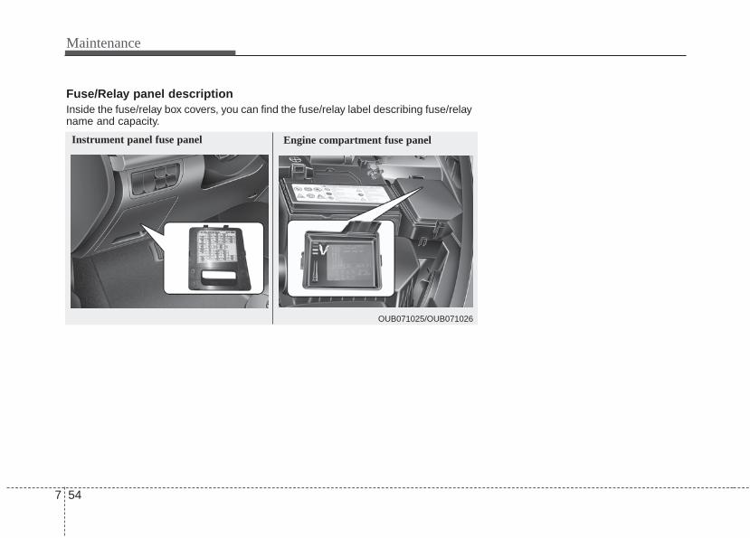
Maintenance
547
Engine compartment fuse panel
OUB071025/OUB071026
Instrument panel fuse panel
Fuse/Relay panel descriptionInside the fuse/relay box covers, you can find the fuse/relay label describing fuse/relayname and capacity.
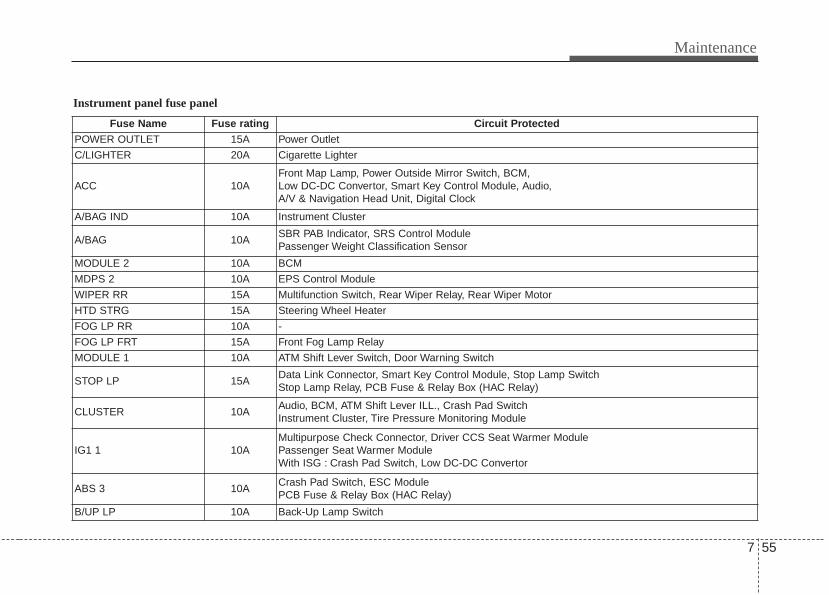
7 55
Maintenance
Instrument panel fuse panel
Fuse Name Fuse rating Circuit ProtectedPOWER OUTLET 15A Power Outlet
C/LIGHTER 20A Cigarette Lighter
ACC 10AFront Map Lamp, Power Outside Mirror Switch, BCM,Low DC-DC Convertor, Smart Key Control Module, Audio,A/V & Navigation Head Unit, Digital Clock
A/BAG IND 10A Instrument Cluster
A/BAG 10ASBR PAB Indicator, SRS Control ModulePassenger Weight Classification Sensor
MODULE 2 10A BCM
MDPS 2 10A EPS Control Module
WIPER RR 15A Multifunction Switch, Rear Wiper Relay, Rear Wiper Motor
HTD STRG 15A Steering Wheel Heater
FOG LP RR 10A -
FOG LP FRT 15A Front Fog Lamp Relay
MODULE 1 10A ATM Shift Lever Switch, Door Warning Switch
STOP LP 15AData Link Connector, Smart Key Control Module, Stop Lamp SwitchStop Lamp Relay, PCB Fuse & Relay Box (HAC Relay)
CLUSTER 10AAudio, BCM, ATM Shift Lever ILL., Crash Pad SwitchInstrument Cluster, Tire Pressure Monitoring Module
IG1 1 10AMultipurpose Check Connector, Driver CCS Seat Warmer ModulePassenger Seat Warmer ModuleWith ISG : Crash Pad Switch, Low DC-DC Convertor
ABS 3 10ACrash Pad Switch, ESC ModulePCB Fuse & Relay Box (HAC Relay)
B/UP LP 10A Back-Up Lamp Switch

Maintenance
567
Fuse Name Fuse rating Circuit Protected
PCU 10AVehicle Speed Sensor, Stop Lamp Switch, InverterA/C Control Module
HAZARD 15A Hazard Switch, BCM
PDM 1 25A Smart Key Control Module
SUNROOF 15A Sunroof Motor
PDM 2 10AImmobilizer Module, Start/Stop Button Switch,Smart Key Control Module
TCU 15ASmart Key Control Module, Immobilizer Module,ECM/PCM, Transaxle Range Switch
IGN COIL 15A Ignition Coil #1/#2/#3/#4, Condenser
IG2 1 10A
BCM, Smart Key Control Module, Driver CCS Seat Warmer ModuleCluster Ionizer, Rain Sensor, A/C Control Module, Sunroof MotorPCB Fuse & Relay Box (Blower Relay, Head Lamp (HI) Relay,Fuel Pump #1 Relay)
WIPER FRT 25AMultifunction Switch, Front Wiper MotorPCB Fuse & Relay Box (Rain Sensor Relay, Front Wiper Relay)
DOOR LOCK 20ADoor Lock/Unlock Relay, Tail Gate Unlock Relay,Two Turn Unlock Relay
SAFETY POWER WINDOW
25A Driver Safety Power Window Module
S/HEATER 2 15ASeat Warmer Switch, Driver CCS Seat Warmer Module,Passenger Seat Warmer Module
FOLD'G MIRR 10A Power Outside Mirror Switch
ROOM LP 10ABCM, Door Warning Switch, Tire Pressure Monitoring ModuleInstrument Cluster, Digital Clock, A/C Control ModuleLuggage Lamp

7 57
Maintenance
Fuse Name Fuse rating Circuit Protected
AUDIO 20AWith ISG : Low DC-DC ConvertorW/O ISG : Audio, A/V & Navigation Head Unit
TAIL LP LH 10AHead Lamp LH, License LampRear Combination Lamp (IN/OUT) LH
TAIL LP RH 10AHead Lamp RH, License Lamp, ILL. (+),Rear Combination Lamp (IN/OUT) RH
START 10A
With Burglar Alarm : Burglar Alarm RelayW/O Burglar Alarm : Transaxle Range Switch (A/T),Smart Key Control Module (M/T), Ignition Lock Switch (M/T),ECM (M/T), PCB Fuse & Relay Box (Start Relay) (M/T)
P/WDW LH 25APower Window Main Switch, Rear Power Window Switch LHDriver Safety Power Window Module
P/WDW RH 25APower Window Main Switch, Rear Power Window Switch RHPassenger Power Window Switch
HTD MIRR 10AECM/PCM, A/C Control ModuleDriver/Passenger Power Outside Mirror
A/CON 10A A/C Control Module

Maintenance
587
Engine compartment fuse panel
Fuse Name Fuse rating Circuit Protected
MULTIFUSE
MDPS 80A EPS Control Module
ALT 125A Alternator
FUSE
B+1 50AI/P Junction Box (Power Connector Fuse : ROOM LP 10A / AUDIO 20A, Fuse : FOG LP FRT 15A / MODULE 1 10A / STOP LP 15A, Tail Lamp Relay)
INVERTER 40A Inverter
B+2 50AI/P Junction Box (Fuse : HAZARD 15A / PDM 1 25A / PDM 2 10A / SUNROOF 15A / DR LOCK 20A / SAFETY POWER WINDOW 25A / S/HEATER 2 15A, FOLD'G MIRR 10A / Power Window Relay)
IG1 40AWith Smart Key - PDM Relay Box (ESCL (ACC) Relay, ESCL (IG1) Relay)W/O Smart Key - Ignition Switch
ABS1 40A ESC Module, Multipurpose Check Connector
ABS2 40A ESC Module
RR HTD 40A I/P Junction Box (Rear Defogger Relay)
ECU_VM 10A PCM
H/LP HI IND 10A Instrument Cluster

7 59
Maintenance
Engine compartment main fuse panelFuse Name Fuse rating Circuit Protected
IG2 40APCB Fuse & Relay Box (Start Relay), W/O Smart Key - Ignition Switch, With Smart Key - PDM Relay Box (ESCL (IG2) Relay)
ECU1 30A PCB Fuse & Relay Box (Engine Control Relay, ECU2 10A)
BLOWER 40A PCB Fuse & Relay Box (Blower Relay)
C/FAN 40A PCB Fuse & Relay Box (Cooling Fan (Low) Relay, Cooling Fan (Hi) Relay)
F/PUMP1 20A PCB Fuse & Relay Box (Fuel Pump #1 Relay)
H/LP HI 20A PCB Fuse & Relay Box (Head Lamp (HI) Relay)
H/LP 20A PCB Fuse & Relay Box (Head Lamp (LO) Relay)
HORN 10A PCB Fuse & Relay Box (Horn Relay, Burglar Alarm Horn Relay)
ECU2 10A M/T - ECM, A/T - E/R Junction Box (ECU_VM 10A)
B/UP LP 10A A/T - PCM, Transaxle Range Switch
WIPER 10A ECM/PCM, Rain Sensor
ECU4 20A ECM/PCM
INJECTOR 15A ECM/PCM, PCB Fuse & Relay Box (Fuel Pump #1 Relay)
H/LP LH 10A Head Lamp LH
SENSOR1 10APurge Control Solenoid Valve, Variable Intake Solenoid Valve, Canister Close Valve, PCB Fuse & Relay Box (Cooling Fan (Low) Relay, Cooling Fan (Hi) Relay)
SENSOR2 10A Oil Control Valve #1/#2, Oxygen Sensor (Up/Down)
H/LP RH 10A Head Lamp RH

Maintenance
607
APPEARANCE CAREExterior careExterior general caution It is very important to follow the labeldirections when using any chemicalcleaner or polish. Read all warning andcaution statements that appear on thelabel.
Finish maintenanceWashing To help protect your vehicle’s finish fromrust and deterioration, wash it thoroughlyand frequently at least once a month withlukewarm or cold water.If you use your vehicle for off-road driv-ing, you should wash it after each off-road trip. Pay special attention to theremoval of any accumulation of salt, dirt,mud, and other foreign materials. Makesure the drain holes in the lower edges ofthe doors and rocker panels are keptclear and clean.Insects, tar, tree sap, bird droppings,industrial pollution and similar depositscan damage your vehicle’s finish if notremoved immediately.Even prompt washing with plain watermay not completely remove all thesedeposits. A mild soap, safe for use onpainted surfaces, may be used.After washing, rinse the vehicle thor-oughly with lukewarm or cold water. Donot allow soap to dry on the finish.
After washing the vehicle, test the brakeswhile driving slowly to see if they havebeen affected by water. If braking per-formance is impaired, dry the brakes byapplying them lightly while maintaining aslow forward speed.

7 61
Maintenance
WaxingWax the vehicle when water will nolonger bead on the paint.Always wash and dry the vehicle beforewaxing. Use a good quality liquid orpaste wax, and follow the manufacturer’sinstructions. Wax all metal trim to protectit and to maintain its luster.Removing oil, tar, and similar materialswith a spot remover will usually strip thewax from the finish. Be sure to re-waxthese areas even if the rest of the vehicledoes not yet need waxing.
Finish damage repair Deep scratches or stone chips in thepainted surface must be repairedpromptly. Exposed metal will quickly rustand may develop into a major repairexpense.If your vehicle is damaged and requiresany metal repair or replacement, be surethe body shop applies anti-corrosionmaterials to the parts repaired orreplaced.
CAUTION - Wetting engine• Water washing in the engine com-
partment including high pressurewater washing may cause the fail-ure of electrical circuits located inthe engine compartment.
• Never allow water or other liquidsto come in contact with electri-cal/electronic components insidethe vehicle as this may damagethem.
OJB037800
CAUTION - Drying vehicle• Wiping dust or dirt off the body
with a dry cloth will scratch thefinish.
• Do not use steel wool, abrasivecleaners, or strong detergentscontaining highly alkaline orcaustic agents on chrome-platedor anodized aluminum parts. Thismay result in damage to the pro-tective coating and cause discol-oration or paint deterioration.

Maintenance
627
Bright-metal maintenance• To remove road tar and insects, use a
tar remover, not a scraper or othersharp object.
• To protect the surfaces of bright-metalparts from corrosion, apply a coating ofwax or chrome preservative and rub toa high luster.
• During winter weather or in coastalareas, cover the bright metal parts witha heavier coating of wax or preserva-tive. If necessary, coat the parts withnon-corrosive petroleum jelly or otherprotective compound.
Underbody maintenanceCorrosive materials used for ice andsnow removal and dust control may col-lect on the underbody. If these materialsare not removed, accelerated rusting canoccur on underbody parts such as thefuel lines, frame, floor pan and exhaustsystem, even though they have beentreated with rust protection.Thoroughly flush the vehicle underbodyand wheel openings with lukewarm orcold water once a month, after off-roaddriving and at the end of each winter. Payspecial attention to these areas becauseit is difficult to see all the mud and dirt. Itwill do more harm than good to wet downthe road grime without removing it. Thelower edges of doors, rocker panels, andframe members have drain holes thatshould not be allowed to clog with dirt;trapped water in these areas can causerusting.
Aluminum or chrome wheel mainte-nance The aluminum or chrome wheels arecoated with a clear protective finish.• Do not use any abrasive cleaner, pol-
ishing compound, solvent, or wirebrushes on aluminum or chromewheels. They may scratch or damagethe finish.
• Clean the wheel when it has cooled.• Use only a mild soap or neutral deter-
gent, and rinse thoroughly with water.Also, be sure to clean the wheels afterdriving on salted roads. This helps pre-vent corrosion.
• Avoid washing the wheels with high-speed car wash brushes.
• Do not use any alkaline or acid deter-gents. It may damage and corrode thealuminum or chrome wheels coatedwith a clear protective finish.

7 63
Maintenance
Corrosion protectionProtecting your vehicle from corrosionBy using the most advanced design andconstruction practices to combat corro-sion, we produces vehicles of the highestquality. However, this is only part of thejob. To achieve the long-term corrosionresistance your vehicle can deliver, theowner's cooperation and assistance isalso required.
Common causes of corrosionThe most common causes of corrosionon your vehicle are:• Road salt, dirt and moisture that is
allowed to accumulate underneath thevehicle.
• Removal of paint or protective coatingsby stones, gravel, abrasion or minorscrapes and dents which leave unpro-tected metal exposed to corrosion.
High-corrosion areasIf you live in an area where your vehicleis regularly exposed to corrosive materi-als, corrosion protection is particularlyimportant. Some of the common causesof accelerated corrosion are road salts,dust control chemicals, ocean air andindustrial pollution.
Moisture breeds corrosionMoisture creates the conditions in whichcorrosion is most likely to occur. Forexample, corrosion is accelerated byhigh humidity, particularly when tempera-tures are just above freezing. In suchconditions, the corrosive material is keptin contact with the vehicle surfaces bymoisture that is slow to evaporate.Mud is particularly corrosive because itdries slowly and holds moisture in con-tact with the vehicle. Although the mudappears to be dry, it can still retain themoisture and promote corrosion.High temperatures can also acceleratecorrosion of parts that are not properlyventilated so the moisture can be dis-persed. For all these reasons, it is par-ticularly important to keep your vehicleclean and free of mud or accumulationsof other materials. This applies not onlyto the visible surfaces but particularly tothe underside of the vehicle.
To help prevent corrosionYou can help prevent corrosion from get-ting started by observing the following:
Keep your vehicle cleanThe best way to prevent corrosion is tokeep your vehicle clean and free of cor-rosive materials. Attention to the under-side of the vehicle is particularly impor-tant.
• If you live in a high-corrosion area —where road salts are used, near theocean, areas with industrial pollution,acid rain, etc.—, you should take extracare to prevent corrosion. In winter,hose off the underside of your vehicleat least once a month and be sure toclean the underside thoroughly whenwinter is over.

Maintenance
647
• When cleaning underneath the vehicle,give particular attention to the compo-nents under the fenders and otherareas that are hidden from view. Do athorough job; just dampening the accu-mulated mud rather than washing itaway will accelerate corrosion ratherthan prevent it. Water under high pres-sure and steam are particularly effec-tive in removing accumulated mud andcorrosive materials.
• When cleaning lower door panels,rocker panels and frame members, besure that drain holes are kept open sothat moisture can escape and not betrapped inside to accelerate corrosion.
Keep your garage dryDon't park your vehicle in a damp, poorlyventilated garage. This creates a favor-able environment for corrosion. This isparticularly true if you wash your vehiclein the garage or drive it into the garagewhen it is still wet or covered with snow,ice or mud. Even a heated garage cancontribute to corrosion unless it is wellventilated so moisture is dispersed.
Keep paint and trim in good conditionScratches or chips in the finish should becovered with "touch-up" paint as soon aspossible to reduce the possibility of cor-rosion. If bare metal is showing through,the attention of a qualified body and paintshop is recommended.
Bird droppings : Bird droppings are high-ly corrosive and may damage paintedsurfaces in just a few hours. Alwaysremove bird droppings as soon as possi-ble.
Don't neglect the interiorMoisture can collect under the floor matsand carpeting and cause corrosion.Check under the mats periodically to besure the carpeting is dry. Use particularcare if you carry fertilizers, cleaningmaterials or chemicals in the car.These should be carried only in propercontainers and any spills or leaks shouldbe cleaned up, flushed with clean waterand thoroughly dried.
Interior careInterior general precautions Prevent caustic solutions such as per-fume and cosmetic oil from contactingthe dashboard because they may causedamage or discoloration. If they do con-tact the dashboard, wipe them off imme-diately. See the instructions for the prop-er way to clean vinyl.
CAUTION - Electrical components
Never allow water or other liquidsto come in contact withelectrical/electronic componentsinside the vehicle as this may dam-age them.
CAUTION - LeatherWhen cleaning leather products(steering wheel, seats etc.), useneutral detergents or low alcoholcontent solutions. If you use highalcohol content solutions oracid/alkaline detergents, the colorof the leather may fade or the sur-face may get stripped off.
7 65
Maintenance
Cleaning the upholstery and interiortrim Vinyl Remove dust and loose dirt from vinylwith a whisk broom or vacuum cleaner.Clean vinyl surfaces with a vinyl cleaner.
Fabric Remove dust and loose dirt from fabricwith a whisk broom or vacuum cleaner.Clean with a mild soap solution recom-mended for upholstery or carpets.Remove fresh spots immediately with afabric spot cleaner. If fresh spots do notreceive immediate attention, the fabriccan be stained and its color can beaffected. Also, its fire-resistant propertiescan be reduced if the material is notproperly maintained.Using anything but recommended clean-ers and procedures may affect the fab-ric’s appearance and fire-resistant prop-erties.
Cleaning the lap/shoulder belt web-bing Clean the belt webbing with any mildsoap solution recommended for cleaningupholstery or carpet. Follow the instruc-tions provided with the soap. Do notbleach or re-dye the webbing becausethis may weaken it.
Cleaning the interior window glass If the interior glass surfaces of the vehi-cle become fogged (that is, covered withan oily, greasy or waxy film), they shouldbe cleaned with glass cleaner. Follow thedirections on the glass cleaner container.
CAUTION - Rear windowsDo not scrape or scratch the insideof the rear window. This may resultin damage to the rear windowdefroster grid.

Maintenance
667
EMISSION CONTROL SYSTEMThe emission control system of yourvehicle is covered by a written limitedwarranty. Please see the warranty infor-mation contained in the Warranty &Maintenance booklet in your vehicle.Your vehicle is equipped with an emis-sion control system to meet all applicableemission regulations.There are three emission control sys-tems, as follows.
(1) Crankcase emission control system(2) Evaporative emission control system(3) Exhaust emission control system
In order to assure the proper function ofthe emission control systems, it is rec-ommended that you have your vehicleinspected and maintained by an author-ized Kia dealer in accordance with themaintenance schedule in this manual.
Caution for the Inspection andMaintenance Test (With ElectronicStability Control (ESC) system)• To prevent the vehicle from misfir-
ing during dynamometer testing,turn the Electronic Stability Control(ESC) system off by pressing theESC switch.
• After dynamometer testing is com-pleted, turn the ESC system back onby pressing the ESC switch again.
1. Crankcase emission controlsystem
The positive crankcase ventilation sys-tem is employed to prevent air pollutioncaused by blow-by gases being emittedfrom the crankcase. This system suppliesfresh filtered air to the crankcase throughthe air intake hose. Inside the crankcase,the fresh air mixes with blow-by gases,which then pass through the PCV valveinto the induction system.
2. Evaporative emission control(including ORVR: OnboardRefueling Vapor Recovery) system
The Evaporative Emission ControlSystem is designed to prevent fuelvapors from escaping into the atmos-phere.(The ORVR system is designed to allowthe vapors from the fuel tank to beloaded into a canister while refueling atthe gas station, preventing the escape offuel vapors into the atmosphere.)

7 67
Maintenance
CanisterFuel vapors generated inside the fueltank are absorbed and stored in theonboard canister. When the engine isrunning, the fuel vapors absorbed in thecanister are drawn into the surge tankthrough the purge control solenoid valve.
Purge Control Solenoid Valve (PCSV)The purge control solenoid valve is con-trolled by the Engine Control Module(ECM); when the engine coolant temper-ature is low during idling, the PCSV clos-es so that evaporated fuel is not takeninto the engine. After the engine warmsup during ordinary driving, the PCSVopens to introduce evaporated fuel to theengine.
3. Exhaust emission control system
The Exhaust Emission Control System isa highly effective system which controlsexhaust emissions while maintaininggood vehicle performance.
Vehicle modifications This vehicle should not be modified.Modification of your vehicle could affectits performance, safety or durability andmay even violate governmental safetyand emissions regulations.In addition, damage or performanceproblems resulting from any modificationmay not be covered under warranty.• If you use unauthorized electronic
devices, it may cause the vehicle tooperate abnormally, wire damage, bat-tery discharge and fire. For your safety,do not use unauthorized electronicdevices.
Engine exhaust gas precautions(carbon monoxide) • Carbon monoxide can be present with
other exhaust fumes. Therefore, if yousmell exhaust fumes of any kind insideyour vehicle, have it inspected andrepaired immediately. If you ever sus-pect exhaust fumes are coming intoyour vehicle, drive it only with all thewindows fully open. Have your vehiclechecked and repaired immediately.
WARNING - ExhaustEngine exhaust gases contain car-bon monoxide (CO). Though color-less and odorless, it is dangerousand could be lethal if inhaled.Follow the instructions on thispage to avoid CO poisoning.

Maintenance
687
• Do not operate the engine in confinedor closed areas (such as garages) anymore than what is necessary to movethe vehicle in or out of the area.
• When the vehicle is stopped in anopen area for more than a short timewith the engine running, adjust theventilation system (as needed) to drawoutside air into the vehicle.
• Never sit in a parked or stopped vehi-cle for any extended time with theengine running.
• When the engine stalls or fails to start,excessive attempts to restart theengine may cause damage to theemission control system.
Operating precautions for catalyticconverters (if equipped)
Your vehicle is equipped with a catalyticconverter emission control device.Therefore, the following precautionsmust be observed:
• Use only UNLEADED FUEL for gaso-line engines.
• Do not operate the vehicle when thereare signs of engine malfunction, suchas misfire or a noticeable loss of per-formance.
• Do not misuse or abuse the engine.Examples of misuse are coasting withthe ignition off and descending steepgrades in gear with the ignition off.
• Do not operate the engine at high idlespeed for extended periods (5 minutesor more).
• Do not modify or tamper with any partof the engine or emission control sys-tem. All inspections and adjustmentsmust be made by an authorized Kiadealer.
• Avoid driving with a extremely low fuellevel. Running out of fuel could causethe engine to misfire, damaging thecatalytic converter.
Failure to observe these precautionscould result in damage to the catalyticconverter and to your vehicle.Additionally, such actions could void yourwarranties.
WARNING - Fire• Do not park, idle or drive the vehi-
cle over or near flammableobjects, such as grass, vegeta-tion, paper, leaves, etc. A hotexhaust system can ignite flam-mable items under your vehicle.
• Also, do not remove the heat sinkaround the exhaust system, donot seal the bottom of the vehicleor do not coat the vehicle for cor-rosion control. It may present afire risk under certain conditions.
WARNING - Catalytic converter
Keep away from the catalytic con-verter and exhaust system whilethe vehicle is running or immedi-ately thereafter. The exhaust andcatalytic systems are very hot andmay burn you.

Engine / 8-2Dimensions / 8-2Bulb wattage / 8-3Tires and wheels / 8-4Weight/Volume / 8-4Recommended lubricants and capacities / 8-5Vehicle identification number (VIN) / 8-7Vehicle certification label / 8-7Tire specification and pressure label / 8-8Engine number / 8-8Refrigerant label / 8-8
Specifications & Consumer information 8

Specifications, Consumer information, Reporting safety defects
28
ENGINE
DIMENSIONS
Item Gasoline 1.6
Displacement [cc(cu.in)]1,591
(97.09)
Bore x Stroke [mm(in)]77 x 85.44
(3.03 x 3.36)
Firing order 1-3-4-2
No. of cylinders 4, In-line
Item mm (in)
Overall length 4045 (159.2)
Overall width 1720 (67)
Overall height 1455 (57.2)
Front tread
185/65R15 1521 (59.8)
195/55R16 1507 (59.3)
205/45R17 1507 (59.3)
Rear tread
185/65R15 1525 (60)
195/55R16 1511 (59.4)
205/45R17 1511 (59.4)
Wheelbase 2570 (101.1)

8 3
Specifications, Consumer information, Reporting safety defects
BULB WATTAGE
Light Bulb Wattage Bulb type
Front
Head lamp Low 55W H11B
High 55W H11B
Position lamp 8W or LED PY28/8W or LED
DRL (Day time Running Lamp)* 21W or LED P21/5W or LED
Turn signal lamp 21W or 28W PY21W or PY28/8W
Front fog lamp* 55W 9006
Side marker light 5W W5W
Rear
Tail lampInside 5W or LED W5W or LED
Outside 8W or LED 28/8W or LED
Stop lampInside 8.7W LED *
Outside 8W or LED 28/8W or LED
Turn signal lamp 21W PY21W
Back up lamp 16W W16W
High mounted stop lamp 2.2W LED
License plate lamp 5W X 2EA W5W
Side marker light*as tail bulb*
LED LED*
Interior
Map lamps* 10W X 2EA W10W
Room lamps 10W FESTON
Luggage lamp 5W FESTON
Glove box lamp 5W FESTON
Vanity mirror lamps* 5W FESTON
* : if equipped

Specifications, Consumer information, Reporting safety defects
48
TIRES AND WHEELS
Item Tire size Wheel size
Cold tire inflation pressure kPa (psi)Wheel lug nut torque
kg•m (lb•ft, N•m)Normal load Maximum load
Front Rear Front Rear
Full size tireP185/65R15* 5.5J X 15
220(32)
220(32)
220(32)
220(32) 9~11
(65~79, 88~107)
P195/55R16* 6.0J X 16P205/45R17* 6.5J X 17
Compact*spare tire
T125/80D15 3.5J X 15420 (60)
420 (60)
420 (60)
420 (60)
* : if equipped
ItemGasoline 1.6
M/T A/T
Gross vehicle weight kg (lbs.)
1600(3525)
1630(3595)
Luggage volumel (cu ft)
MIN 288 (10)
MAX 923 (32)
WEIGHT/VOLUME

8 5
Specifications, Consumer information, Reporting safety defects
RECOMMENDED LUBRICANTS AND CAPACITIESTo help achieve proper engine and powertrain performance and durability, use only lubricants of the proper quality. The correctlubricants also help promote engine efficiency that results in improved fuel economy.
These lubricants and fluids are recommended for use in your vehicle.
*1 Refer to the recommended SAE viscosity numbers on the next page.*2 Engine oils labeled Energy Conserving Oil are now available. Along with other additional benefits, they contribute to fuel economy by reducing
the amount of fuel necessary to overcome engine friction. Often, these improvements are difficult to measure in everyday driving, but in a year’stime, they can offer significant cost and energy savings.
*3 If the API service SM engine oil is not available in your country, you are able to use API service SL.
Lubricant Volume ClassificationEngine oil *1 *2 (drain and refill)
Recommended3.3 l (3.49 US qt.)
API Service SM*3,
(or equivalent) ILSAC GF-4 or above
Manual transaxle fluid1.8 ~ 1.9 l API GL-4, SAE 75W/85
(1.9 ~ 2.01 US qt.) approved by Kia Motors Corp.
Automatic transaxle fluid 1.6 Engine 7.3 l (7.71 US qt.)MICHANG ATF SP-IV, SK ATF SP-IV
NOCA ATF SP-IV, Kia genuine ATF SP-IV
Automatic transaxle 5.5 l (5.6 US qt.) Mixture of antifreeze and distilled water Coolant
Manual transaxle 5.3 l (5.8 US qt.) (Ethylene glycol base coolant for aluminum radiator)
Brake/Clutch fluid0.7~0.8 l
FMVSS116 DOT-3 or DOT-4(0.7~0.8 US qt.)
Fuel 43 l (11.3 US gal.) Refer to “Fuel requirements” in section 1

Specifications, Consumer information, Reporting safety defects
68
Recommended SAE viscositynumberAlways be sure to clean the area aroundany filler plug, drain plug, or dipstickbefore checking or draining any lubricant.This is especially important in dusty orsandy areas and when the vehicle isused on unpaved roads. Cleaning theplug and dipstick areas will prevent dirtand grit from entering the engine andother mechanisms that could be dam-aged.
Engine oil viscosity (thickness) has aneffect on fuel economy and cold weatheroperation (engine start and engine oilflowability). Lower viscosity engine oilscan provide better fuel economy and coldweather performance, however, higherviscosity engine oils are required for sat-isfactory lubrication in hot weather. Usingoils of any viscosity other than those rec-ommended could result in engine dam-age.
When choosing an oil, consider the rangeof temperature your vehicle will be oper-ated in before the next oil change.Proceed to select the recommended oilviscosity from the chart.
Temperature Range for SAE Viscosity Numbers
Temperature
Gasoline Engine Oil *1
°C(°F)
-30 -20 -10 0 10 20 30 40 50-10 0 20 40 60 80 100 120
1. For better fuel economy, it is recommended to use the engine oil ofa viscosity grade SAE 5W-20 (API SM / ILSAC GF-4). However, ifthe engine oil is not available in your country, select the properengine oil using the engine oil viscosity chart.
10W-30
5W-20, 5W-30
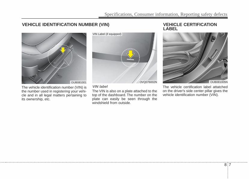
8 7
Specifications, Consumer information, Reporting safety defects
The vehicle identification number (VIN) isthe number used in registering your vehi-cle and in all legal matters pertaining toits ownership, etc.
VIN labelThe VIN is also on a plate attached to thetop of the dashboard. The number on theplate can easily be seen through thewindshield from outside.
The vehicle certification label attatchedon the driver’s side center pillar gives thevehicle identification number (VIN).
VEHICLE CERTIFICATIONLABEL
OVQ076002N
VIN Label (if equipped)
VEHICLE IDENTIFICATION NUMBER (VIN)
OUB081001 OUB081005N

Specifications, Consumer information, Reporting safety defects
88
The tires supplied on your new vehicleare chosen to provide the best perform-ance for normal driving.The tire label located on the driver's sidecenter pillar gives the tire pressures rec-ommended for your vehicle.
The engine number is stamped on theengine block as shown in the drawing. The refrigerant label is located on the
underside of the hood.
OUB081004N
ENGINE NUMBERTIRE SPECIFICATION ANDPRESSURE LABEL
OUB071018 OUB071062N
REFRIGERANT LABEL (IF EQUIPPED)