Embed Size (px)
Citation preview

Strojniški vestnik - Journal of Mechanical Engineering 57(2011)12, 879-887 Paper received: 01.10.2010DOI:10.5545/sv-jme.2010.210 Paper accepted: 27.10.2011
*Corr. Author’s Address: University Carlos III de Madrid, Department of Mechanical Engineering, Avda. De la Universidad, 30, 28911 Leganés, Madrid, Spain, [email protected] 879
Kinematics and Dynamics of the Quasi-Passive Biped “PASIBOT”
Meneses, J. – Castejón, C. – Corral, E. – Rubio, H. – García-Prada, J.C.Jesús Meneses – Cristina Castejón* – Eduardo Corral – Higinio Rubio – Juan Carlos García-PradaUniversity Carlos III de Madrid, Department of Mechanical Engineering, MAQLAB group, Spain
A quasi-passive biped (having only one actuator) developed into a Spanish project called “PASIBOT” [1] is presented in this article. We focus on the PASIBOT’s topology, kinematics and dynamics, and we describe a program designed for carrying out the corresponding calculations. This code provides for all kinematic and dynamic data, as functions of time, along one step: position, velocity and acceleration of all members, as well as all the forces and torques on each of them, motor torque included. This latter information has helped us to choose the required motor, as this choice depends on some parameters of interest that can be modified in the program, like density or link dimensions. Also, we will be able to get strain-stress data in all links in the course of a step, and then optimize those dimensions. To finish, some results are also presented that confirm the interest of the developed code.©2011 Journal of Mechanical Engineering. All rights reserved. Keywords: mechanism analysis, quasi-passive biped, walking robots
0 INTRODUCTION
Currently, service robotics is one of the main research priority areas. The application of robots for service tasks (personal assistance, education, social tasks, etc.) makes its design very important. Current mobile robots are not adapted to be used in domestic environments due to their large volume and/or weight, and their lack of maneuverability in these complex scenes. The interest in the development of humanoid robotics (which perform the tasks commented before) is increasing and such robots are being developed by a great number of research groups in the entire world [2] and [3].
Nowadays, humanoid robots are formed by a high number of actuators, used to control the high degrees of freedom (DOF) they have [4]. On the other hand, one of the biggest drawbacks in humanoids is the weight and power consumption. In the majority of them, around 30% of the total weight is due to the actuators and wires, and more than 25% is due to the reduction systems coupled [5]. For this reason, this work focuses on the design of new mechanisms and kinematic chains which, maintaining the robot capabilities, require a smaller number of actuators. This would reduce the robot mass and hence, its power consumption and the total cost.
During the last few years, different research groups have developed robots based on passive walking techniques [6]. An example is the one meter length Robot Ranger of Cornell University [7] with three joints in each of its long legs. The robot can walk in a similar way to a human, by means of the balance and the dynamic of the natural swinging, in order to consume the minimum energy to walk. Robot Toddlers from MIT University [8] is a small robot that only has a single passive pin joint at the hip, while the 3D movement is achieved by means of the feet surface design. Toddlers is designed only to walk down a shallow slope. Robot Denise from Delft University [9] is a pneumatically powered walking robot with human configuration and five DOF, and the last robot of interest in the passive theory is the one developed in the Nagoya Institute of Technology [10] whose topology is similar to Denise Robot but it only presents two legs, and it includes a stability mechanism of fixed point [11].
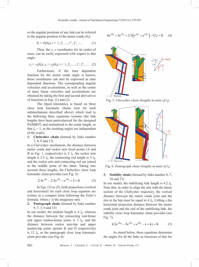
In this article, a human size biped, called PASIBOT, with low DOF, which represents a qualitative improvement in the service robotic field, is presented. The innovative design has been carried out with the combination of classical mechanisms (Peaucellier, Watt, pantograph [12], etc.). This prototype is based on the one designed and built at the Laboratory of Robotics and Mechatronics in Cassino (LARM) [13] and

Strojniški vestnik - Journal of Mechanical Engineering 57(2011)12, 879-887
880 Meneses, J. – Castejón, C. – Corral, E. – Rubio, H. – García-Prada, J.C.
[14], following the philosophy of low cost [15]. A similar leg design has also been used in a four legs walking chair [16].
The proposed mechanism is an arrangement of links in the planar movement that has only one DOF. In this manuscript, the planar kinematics and dynamics analysis of PASIBOT is presented. The study is performed from a theoretical point of view, and aims at obtaining the linear and angular position coordinates, velocities and accelerations for all links, as well as all the forces and torques between links including motor torque, for any time in the course of one step. The expressions have been implemented in MATLAB® code, and the corresponding results have been used in the design and construction of a real prototype, and they are being used in movement control tasks.
In the section “topological description of PASIBOT”, the biped PASIBOT mechanism is described by defining its subassemblies and parts, and the nomenclature used; next, in the section “Kinematics of PASIBOT”, it is explained how to deduce the expressions for the angular and linear position, velocities and accelerations for all the links of the biped; then, in “Dynamics of PASIBOT”, the method of obtaining all the forces and torques on every link, at every time in the course of one step of PASIBOT is presented; in “Numerical results” a code designed to calculate the kinematical and dynamical values for different set of parameters (motor angular velocity, density, link dimensions, etc.), including the corresponding results is presented; and finally, the conclusions of this work are presented.
1 TOPOLOGICAL DESCRIPTION OF PASIBOT
The biped presented in this article (see Figs. 2 to 4), is a mechanism that can be divided into three essential subassemblies or “sub-mechanisms”, each of them having a particular function:1. Quasi-straight line generator mechanism
(Chebyshev);2. Amplifier mechanism (pantograph);3. Stability extension and foot (parallelogram
extensions).In Fig. 1, the coupling Chebyshev-
pantograph mechanism is shown, together with
two trajectories tracked by the points of interest. Chebyshev mechanism transfers the motor rotational movement at its crank into a continuous cyclical trajectory, which is composed of a curved section and a quasi-straight one, at the end of its connecting rod (Fig. 1, point C). This point is then linked to a pantograph mechanism in such a way that its free end (Fig. 1, point E) executes a trajectory that is inverted and amplified with respect to that described above. The ratio of magnification of the pantograph depends on the dimension of its bars; for the design presented in this work, this ratio is two.
Fig. 1. Coupling Chebyshev-Pantograph mechanism with the corresponding trajectories of
interest
The relative positions of points A, B and D in Fig. 1, are fixed at the member called “hip”, shown in Fig. 2. The hip also carries a slot (see Fig. 2) which is the base of the stabilization system: a set of links arranged in parallelograms with the two longest bars of the pantograph. This stability extension guarantees the parallelism between the supporting foot and the stabilizing bar, whose end slides along the slot at the hip. The first approach is to align the slot with the linear section of the Chebyshev trajectory, in such a way that the supporting foot remains also parallel to the slot.
To provide the opposite leg with the proper movement, the corresponding crank is phased out
Strojniški vestnik - Journal of Mechanical Engineering 57(2011)12, 879-887
881Kinematics and Dynamics of the Quasi-Passive Biped “PASIBOT”
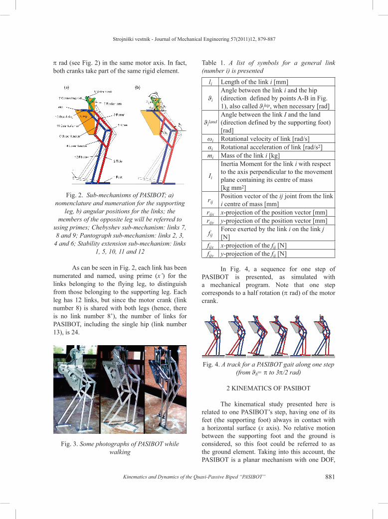
p rad (see Fig. 2) in the same motor axis. In fact, both cranks take part of the same rigid element.
Fig. 2. Sub-mechanisms of PASIBOT; a) nomenclature and numeration for the supporting
leg, b) angular positions for the links; the members of the opposite leg will be referred to
using primes; Chebyshev sub-mechanism: links 7, 8 and 9; Pantograph sub-mechanism: links 2, 3,
4 and 6; Stability extension sub-mechanism: links 1, 5, 10, 11 and 12
As can be seen in Fig. 2, each link has been numerated and named, using prime (x’) for the links belonging to the flying leg, to distinguish from those belonging to the supporting leg. Each leg has 12 links, but since the motor crank (link number 8) is shared with both legs (hence, there is no link number 8’), the number of links for PASIBOT, including the single hip (link number 13), is 24.
Fig. 3. Some photographs of PASIBOT while walking
Table 1. A list of symbols for a general link (number i) is presented
li Length of the link i [mm]
ϑi
Angle between the link i and the hip (direction defined by points A-B in Fig. 1), also called ϑihip, when necessary [rad]
ϑilandAngle between the link I and the land (direction defined by the supporting foot) [rad]
ωi Rotational velocity of link [rad/s]αi Rotational acceleration of link [rad/s2]mi Mass of the link i [kg]
Ii
Inertia Moment for the link i with respect to the axis perpendicular to the movement plane containing its centre of mass [kg mm2]
rijPosition vector of the ij joint from the link i centre of mass [mm]
rijx x-projection of the position vector [mm]rijy y-projection of the position vector [mm]
fijForce exerted by the link i on the link j [N]
fijx x-projection of the fij [N]fijy y-projection of the fij [N]
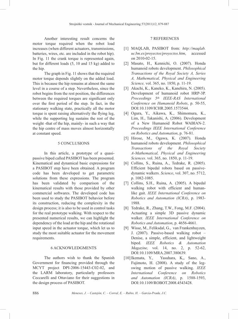
In Fig. 4, a sequence for one step of PASIBOT is presented, as simulated with a mechanical program. Note that one step corresponds to a half rotation (p rad) of the motor crank.
Fig. 4. A track for a PASIBOT gait along one step (from ϑ8= p to 3p/2 rad)
2 KINEMATICS OF PASIBOT
The kinematical study presented here is related to one PASIBOT’s step, having one of its feet (the supporting foot) always in contact with a horizontal surface (x axis). No relative motion between the supporting foot and the ground is considered, so this foot could be referred to as the ground element. Taking into this account, the PASIBOT is a planar mechanism with one DOF,
Strojniški vestnik - Journal of Mechanical Engineering 57(2011)12, 879-887
882 Meneses, J. – Castejón, C. – Corral, E. – Rubio, H. – García-Prada, J.C.
so the angular positions of any link can be referred to the angular position of the motor crank (θ8):
θi = θi(θ8), i = 1, 2, …, 1’, 2’, … (1)
Then, the x, y coordinates for its centre of mass, can be easily expressed with respect to that angle:
xi = xi(θ8); yi = yi(θ8), i = 1, 2, …, 1’, 2’, … (2)
Furthermore, if the time dependent function for the motor crank angle is known, those coordinates can also be expressed as time dependent functions. The corresponding angular velocities and accelerations, as well as the centre of mass linear velocities and accelerations are obtained by taking the first and second derivatives of functions in Eqs. (1) and (2).
The biped kinematics is based on three close loop kinematic chains (one for each submechanism described above) which lead to the following three equations systems (the link lengths have been particularized for the designed PASIBOT, and normalized to the crank length, so that l8 = 1, as the resulting angles are independent of the scale):1. Chebyshev chain (formed by links number
7, 8, 9 and 13)In a Chevyshev mechanism, the distance between motor crank and rocker arm fixed points (A and B in Fig. 1, respectively) is 2 l8, the rocker arm length is 2.5 l8, the connecting rod length is 5 l8, and the rocker arm and connecting rod are joined at the middle point of the latter. Taking into account these lengths, the Chebyshev close loop kinematic chain provides (see Fig. 5):
2 5 2 5 2 07 9 8. . .e e ej j jϑ ϑ ϑ− − + = (3)
In Eqs. (3) to (5), both projections (vertical and horizontal) for each close loop equation are written in a compact form following the Euler’s formula, where j is the imaginary unit.2. Pantograph chain (formed by links number
9, 7, 3, 6 and 13)In our model, the tendons length is 6 l8, whereas the distance between the connecting rod-femur and upper tendon-femur joints is 3 l8, and the distance between rocker arm-hip and upper tendon-hip joints (points B and D respectively) is 12 l8, so the pantograph close loop kinematic chain provides (see Fig. 6):
6 3 2 5 12 06 3 7 9e e e e jj j j jϑ ϑ ϑ ϑ+ + +( ) − =. . (4)
Fig. 5. Chevyshev chain (lengths in units of l8)
Fig. 6. Pantograph chain (lengths in units of l8)
3. Stability chain (formed by links number 8, 7, 10 and 13)
In our model, the stabilizing link length is 4.2 l8. Note that, in order to align the slot with the linear section of the Chebyshev trajectory, the vertical distance between the motor crank joint and the slot at the hip must be equal to 4 l8. Calling x the horizontal projection distance between the motor crank joint and the end of the stabilizing link, the stability close loop kinematic chain provides (see Fig. 7):
4 2 5 4 010 7 8. .e e e x jj j jϑ ϑ ϑ− + − + = (5)
As stated below, these equations determine the angles for all the links as functions of that for

Strojniški vestnik - Journal of Mechanical Engineering 57(2011)12, 879-887
883Kinematics and Dynamics of the Quasi-Passive Biped “PASIBOT”
the motor crank, ϑ8, which is also a function of time.
Fig. 7. Stabilization chain (lengths in units of l8)
Solving the Eq. system (3), the expressions (Eq. (6)) for the connecting rod and rocker arm angles are found.
From Eq. (4), the femur and tibia angles are found as functions of the previous ones. (See Eq. (7)).
Finally, the Eq. (5) gives the solution for the stabilizing angle:
ϑϑ ϑ
107 85 44 2
=⋅ − −
asin
sin sin.
. (8)
As can be seen in Fig. 2, the rest of the angles involved are identical to one of the given ones in the Eqs. (6) to (8), in particular:
ϑ ϑ ϑ ϑ ϑ ϑ ϑ ϑ ϑ1 5 10 12 4 3 2 13 6= = = = = =, , . (9)For the links belonging to the opposite leg,
we apply a phase out of π radians on ϑ8:
ϑ ϑ ϑ ϑ πi i' .8 8( ) = +( ) (10)
All these angles have been calculated using a reference system fixed at the hip, the x-axis direction being defined by the points A and B in Fig. 1. In order to apply the second Newton’s law, all the kinematic values must be referenced to an inertial system. An inertial system can be placed at the ground (or at the supporting foot, link number 1 in Fig. 2, as no relative motion between this link and the ground is considered). The corresponding base change is described in Eq. (11):
ϑ ϑ ϑiground
ihip hip= − 1 , (11)
where ϑiground is the angle of the i-link related to the ground system, and ϑihip is the corresponding one related to the reference system fixed at the hip.
Once the angles are determined in the new reference system, the positions of the center of mass for all the links are easily obtained using trigonometric relations (for example, x2 = L2cosϑ2/2, y2 = L2sinϑ2/2; x3 = L2cosϑ2 + L3cosϑ3/2, y3 = L2sinϑ2 + L3sinϑ3/2; and so on). Then, by time differentiating once and twice, the angular velocity and acceleration respectively for any link,
ϑϑ ϑ ϑ ϑ ϑ
7
28 8 8
28 84 13 10 16 60 100
=− ⋅ + ⋅ − + ⋅ − ⋅ − ⋅ +
acoscos cos sin cos cos
225 20
4 13 10 16
8
9
28 8 8
− ⋅
=− ⋅ + ⋅ − − ⋅ −
cos
coscos cos sin
ϑ
ϑϑ ϑ ϑ
a⋅⋅ − ⋅ +
− + ⋅
cos coscos
,2
8 8
8
60 10025 20
ϑ ϑ
ϑ
(6)
ϑϑ ϑ ϑ ϑ
67 9 7 92 5 27 2 5 12 144
=⋅ + ⋅ − − − ⋅ + − ⋅
aA
cos( . (cos cos ) ( ) . (sin sin ) ⋅⋅ − − −
⋅
=⋅ + ⋅ − +
A AA
aA
( )
cos( . cos cos ) ( ) .
2712
2 5 27 2
2
37 9ϑ
ϑ ϑ 55 12 36 276
7 92⋅ + − ⋅ ⋅ − −
⋅
(sin sin ) ) ( ),
ϑ ϑ A AA
(7)
where: A = ⋅ + + ⋅ + −( . (cos cos )) ( . sin sin ) )2 5 2 5 127 92
7 92ϑ ϑ ϑ ϑ .

Strojniški vestnik - Journal of Mechanical Engineering 57(2011)12, 879-887
884 Meneses, J. – Castejón, C. – Corral, E. – Rubio, H. – García-Prada, J.C.
as well as the linear velocity and acceleration of its center of mass are found.
In summary, the planar kinematics of PASIBOT is solved. As an application, all the kinematical values for one step of PASIBOT have been calculated, considering a motor crank constant angular velocity, ω8:
ϑ8(t) = ω8·t . (12)
3 DYNAMICS OF PASIBOT
The inputs for the dynamical problem are the previously calculated kinematic magnitudes for every link, that is to say, its angular acceleration, αi, and its center of mass acceleration, (aix, aiy). The dynamical magnitudes involved in the complete mechanical study of PASIBOT are the weight of every link, mig, the motor torque, T8, and all the forces between links, fji (exerted by link j on link i). All those kinematical and dynamical magnitudes are presented in Fig. 8, for a general link i.
Fig. 8. Dynamical entities for a general link i
For any link, i, the dynamical equations for the motion of the center of mass and for the rotation of the rigid body, using the action-reaction Newton’s law to reduce the number of unknown forces, are exposed in Eq. (13):
i
i i i
ij ji
ion i i
F m a
f f
T I
∑
∑
=
= −
⇒
=
α
⇒
− =
− = +
+
< >
< >
<
∑ ∑
∑ ∑
∑
j iji
k iik i i
j iji
k iik i i i
ij i
f f m a
f f m g m a
T
x x x
y y y
rr f r f r f r f Iij ji ij jik i
ik ik ik ik i ix y y x x y y x−( ) − −( ) =
>∑ α
= ′ ′ ′ ′ ′
,
, ,..., , , ,... , ,...i 2 3 13 1 2 7 9 12
(13)
Since there are 23 links (excluding the supporting foot) and there are three equations for each link, the system describing the dynamics of the whole mechanism consists of 69 linear equations. The linear equation system (Eq. (13)) is expressed in a matrix form (Eq. (14)), and then solved via matrix inversion, with a MATLAB® code.
a aa a
f
f
T
x
y11 12
21 22
12
12
8
……
� � � �…
�
�
·
=
+
m a
m g m a
I
A coefficien
x
y
2 2
2 2 2
2 2α�
,
( tt F force I inertia
F A I
) · ( ) ( )
· .
[ ][ ] = [ ]⇓
[ ] = [ ] [ ]−1
(14)
4 NUMERICAL RESULTS
The kinematical and dynamical equations have been implemented in a MATLAB code in order to obtain solutions (position, velocities, acceleration, as well as forces and torques) depending of a set of parameters (link dimensions, masses, and densities, motor angular velocity) entered by the user. This code is being integrated into the movement control task. In Fig. 9, the flow chart of the developed algorithm is presented.
For every time step, t, the program first finds the corresponding value of ϑ8(t) and using Eqs. (6) to (11), it obtains those of the rest of the angles and the positions of the centres of mass. Then, using the same variables for t-1 and t-2, it calculates the corresponding angular and linear velocities and accelerations. These data that define the kinematic state of the biped at the time t, form the inertia matrix, [I] in Eq (14). Finally, the program inverts the coefficient matrix, [A], by means of a matrix

Strojniški vestnik - Journal of Mechanical Engineering 57(2011)12, 879-887
885Kinematics and Dynamics of the Quasi-Passive Biped “PASIBOT”
inversion subroutine and multiplies both matrices to provide the forces and torques between links at this time step. These values are stored to be plotted and the calculations restart for the next time step.
Fig. 9. Flow chart for the PASIBOT kinematics and dynamics calculus code
As the first result, the program implemented in MATLAB® has helped us to choose the suitable actuators and transmission systems, as it provides the motor torque required to perform the prescribed movement. This torque actually depends on many parameters that can be easily changed in the program (the masses and sizes of every link independently, or their densities, the motor angular velocity function, among others). The process of choosing the actuator and/or transmission system is iterative: first, the maximum torque without additional weight is calculated, and a motor that provides higher torque, at the prescribed speed, is proposed. Then, the required torque with the additional definite weight of the proposed engine is recalculated, and if this torque exceeds what the proposed motor can provide, the immediately superior motor is proposed, the torque with the corresponding weight is recalculated, and so on; if not, the process ends and the proposed motor is chosen. This code will allow us to quickly obtain all the dynamic and kinematical parameters of interest for control and optimization tasks.
As an example, during construction of the first prototype, the links “femur”, “fibula” and “tibia” had to be doubled in order to increase their resistance. With the program, the calculation of the new torque required was immediate. In that case, the program helped us to design the reduction phase required to be coupled with the same motor
(see Fig. 2).The code programmed has been validated
by comparison with others simulation programs (Working model and ADAMS code). The main advantage of the developed program is that it let us perform fast modifications, making easier the final robot design by selecting new materials, choosing actuators and reduction devices, or even applying any type of optimization process.
As an example of the capacities of the program, some results are presented. Fig. 10 shows the actuator torque in the crank (link number 8) related to time, for different values of the motor angular velocity, ω8.
Fig. 10. Actuator torque for different crank velocities. T is the semi-period for the rotation
of the motor crank, that is, the time for one PASIBOT’s step
In Fig. 10, the same shape for each case can be appreciated apart from the torque obtained from the highest velocity value (ω8 = 5 rad/s). With this velocity; the dynamical effect of the acceleration (inertia force) becomes important.
Fig. 11. Actuator torque for different hip extra loads
Strojniški vestnik - Journal of Mechanical Engineering 57(2011)12, 879-887
886 Meneses, J. – Castejón, C. – Corral, E. – Rubio, H. – García-Prada, J.C.
Another interesting result concerns the motor torque required when the robot load increases (when different actuators, transmissions, batteries, wires, etc. are included in the robot hip). In Fig. 11 the crank torque is represented again, but for different loads (5, 10 and 15 kg) added to the hip.
The graph in Fig. 11 shows that the required motor torque depends slightly on the added load. This is because the hip remains at almost the same level in a course of a step. Nevertheless, since the robot begins from the rest position, the differences between the required torques are significant only over the first period of the step. In fact, in the stationary walking state, practically all the motor torque is spent raising alternatively the flying leg, while the supporting leg sustains the rest of the weight -that of the hip, mainly- in such a way that the hip centre of mass moves almost horizontally at constant speed.
5 CONCLUSIONS
In this article, a prototype of a quasi-passive biped called PASIBOT has been presented. Kinematical and dynamical basic expressions for a PASIBOT step have been obtained. A program code has been developed to get parametric solutions from these expressions. The program has been validated by comparison of the kinematical results with those provided by other commercial softwares. The developed code has been used to study the PASIBOT behavior before its construction, reducing the complexity in the design process; it is also to be used in control tasks for the real prototype walking. With respect to the presented numerical results, we can highlight the dependency of the load at the hip and the rotational input speed in the actuator torque, which let us to study the most suitable actuator for the movement requirements.
6 ACKNOWLEDGMENTS
The authors wish to thank the Spanish Government for financing provided through the MCYT project DPI-2006-15443-C02-02, and the LARM laboratory, particularly professors Ceccarelli and Ottaviano for their suggestions in the design process of PASIBOT.
7 REFERENCES
[1] MAQLAB, PASIBOT from: http://maqlab.uc3m.es/proyectos/proyectos.htm, accessed on 2010-02-15.
[2] Masato, H., Kennichi, O. (2007). Honda humanoid robots development. Philosophical Transactions of the Royal Society A, Series A, Mathematical, Physical and Engineering Science, vol. 365, no. 1850, p. 11-19.
[3] Akachi, K., Kaneko, K., Kanehira, N. (2005). Development of humanoid robot HRP-3P. Proceedings 5th IEEE-RAS International Conference on Humanoid Robots, p. 50-55, DOI:10.1109/ICHR.2005.1573544.
[4] Ogura, Y., Aikawa, K., Shimomura, K., Lim, H., Takanishi, A. (2006). Development of a New Humanoid Robot WABIAN-2. Proceedings IEEE International Conference on Robotics and Automation, p. 76-81.
[5] Hirose, M., Ogawa, K. (2007). Honda humanoid robots development. Philosophical Transactions of the Royal Society A-Mathematical, Physical and Engineering Sciences. vol. 365, no. 1850, p. 11-19.
[6] Collins, S., Ruina, A., Tedrake, R. (2005). Efficient bipedal robots based on passive-dynamic walkers. Science, vol. 307, no. 5712, p. 1082-1085.
[7] Collins, S.H., Ruina, A. (2005). A bipedal walking robot with efficient and human-like gait. IEEE International Conference on Robotics and Automation (ICRA), p. 1983-1988.
[8] Tedrake, R., Zhang, T.W., Fong, M.F. (2004). Actuating a simple 3D passive dynamic walker. IEEE International Conference on Robotics and Automation, p. 4656-4661.
[9] Wisse, M., Feliksdal, G., van Frankenhuyzen, J. (2007). Passive-based walking robot –Denise, a simple, efficient, and lightweight biped. IEEE Robotics & Automation Magazine, vol. 14, no. 2, p. 52-62, DOI:10.1109/MRA.2007.380639.
[10] Ikemata, Y., Yasuhara, K,, Sano, A., Fujimoto, H. (2008). A study of the leg-swing motion of passive walking. IEEE International Conference on Robotics and Automation (ICRA), p. 1588-1593, DOI:10.1109/ROBOT.2008.4543428.

Strojniški vestnik - Journal of Mechanical Engineering 57(2011)12, 879-887
887Kinematics and Dynamics of the Quasi-Passive Biped “PASIBOT”
[11] Ikemata, Y., Sano, A., Fujimoto, H. (2006). A physical principle of gait generation and its stabilization derived from mechanism of fixed point. Proceedings of the 2006 IEEE International Conference on Robotics and Automation, p. 836-841, DOI:10.1109/ROBOT.2006.1641813.
[12] Erdman, A.G., Sandor, G.N. (1997). Mechanism design: analysis and synthesis. 3rd ed., Prentice-Hall, New Jersey.
[13] Gu, H., Ceccarelli, M., Carbone, G. (2008). Design and operation of 1-DOF anthropomorphic arm for humanoid robots. Proceedings of the 17th International Workshop on Robotics in Alpe-Adria-Danube Region RAAD08.
[14] Tavolieri, C., Ottaviano, E., Ceccarelli, M., Di Rienzo, A. (2006). Analysis and design
of a 1-DOF leg for walking machines. Proceedings of RAAD’06, 15th International Workshop on Robotics in Alpe-Adria-Danube Region.
[15] Castejón, C., Carbone, G., García-Prada, J.C., Ceccarelli, M. (2010). A multi-objective optimization of a robotic arm for service tasks. Strojniški vestnik - Journal of Mechanical Engineering, vol. 56, no. 5, p. 316-329.
[16] Hu, Y., Nakamura, H., Takeda, Y., Higuchi, M., Sugimoto, K. (2007). Development of a power assist system of a walking chair based on human arm characteristics. Journal of Advanced Mechanical Design, Systems and Manufacturing, vol. 1, no. 1, p. 141-154, DOI:10.1299/jamdsm.1.141.


![Marcin SZAREK, Gözde ÖZCAN [Biped Robot]](https://img.pdfslide.net/doc/110x75/577cc4671a28aba711992e3b/marcin-szarek-goezde-oezcan-biped-robot.jpg)