Embed Size (px)
Citation preview

Kinematics and Orientations
HierarchiesForward KinematicsTransformations (review) Euler anglesQuaternionsYaw and evaluation function
for assignment 2

Building a character
Just translate, rotate, and scale each body part to get the right size, shape, position, and orientation.
Looks great--until you try to make it move.

The Right Control KnobsAs soon as you want to change
something, the model falls apartReason: the thing you’re modeling is
constrained but your model doesn’t know it
What we need: some sort of representation of structurea set of “control knobs” (parameters) that make it easy
to move our stick person through legal configurations
Key is to structure the transformations in the right way: using a hierarchy

Making an Articulated Model
• A minimal 2-D jointed object:– Two pieces, A (“forearm”) and B (“upper arm”)– Attach point q on B to point r on A (“elbow”)– Desired control knobs:
• T: shoulder position (point at which p winds up)• u: shoulder angle (A and B rotate together about p)• v: elbow angle (A rotates about r, which stays attached to q)
AAr BB qpBBp
AArq
T

Making an Arm, step 1
• Start with A and B in their untransformed configurations (B is hiding behind A)
• First apply a series of transformations to A, leaving B where it is…
AAr
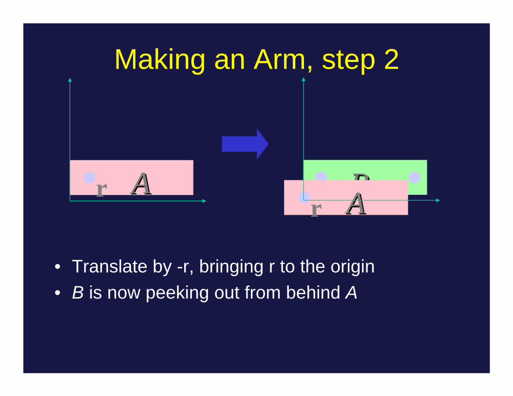
Making an Arm, step 2
• Translate by -r, bringing r to the origin• B is now peeking out from behind A
BB qpAAr
AAr

Making an Arm, step 3
Next, we rotate A by v (the “elbow” angle)
BB qp AArBB qpAAr

Making an Arm, step 4
Translate A by q, bringing r and q together to form the elbow joint
We can regard q as the origin of the lower arm coordinate system, and regard A as being in this coordinate system.
BB qp AArBB qp AAr

Making an Arm, step 5
From now on, each transformation applies to bothA and B (This is important!)
First, translate by -p, bringing p to the originA and B both move together, so the elbow doesn’t
separate
BB qp AArBB qp AAr
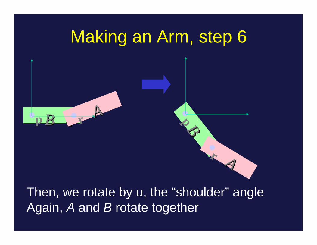
Making an Arm, step 6
Then, we rotate by u, the “shoulder” angle Again, A and B rotate together
BBp
AAr
BB qp AAr

Making an Arm, step 7
Finally, translate by T, bringing the arm where we want it
p is at origin of upper arm coordinate system
BBq
pAAr
BBq
p
AAr
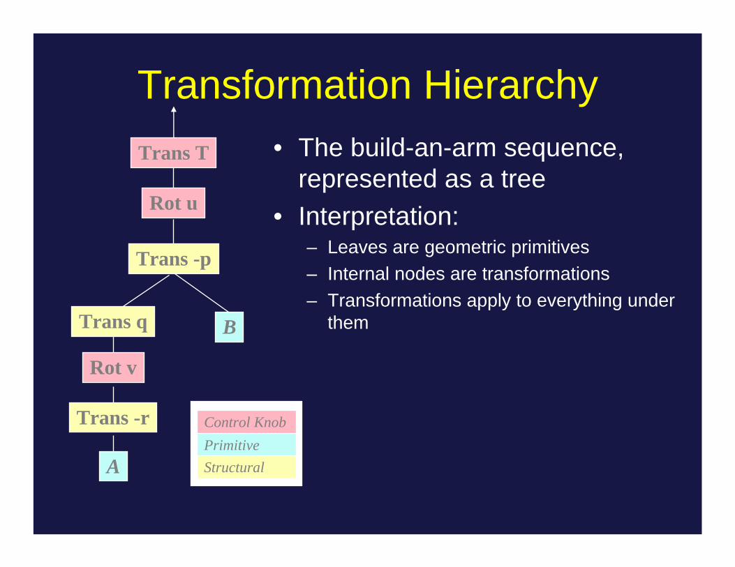
Transformation Hierarchy• The build-an-arm sequence,
represented as a tree• Interpretation:
– Leaves are geometric primitives– Internal nodes are transformations– Transformations apply to everything under
them
Trans -r
Rot v
Trans q
A
Trans -p
Rot u
Trans T
B
Control KnobPrimitiveStructural

Transformation HierarchyAnother point of view:• The shoulder coordinate
transformation moves everything below it with respect to the shoulder:– B– A and its transformation
• The elbow coordinate transformation moves A with respect to the shoulder coordinate transform
Trans -r
Rot v
Trans q
A
Trans -p
Rot u
Trans T
B
Shoulder coordinate xformElbow coordinate xformPrimitive

A Schematic Humanoid• Each node represents
– rotation(s)– geometric primitive(s)– structural transformations
• The root can be anywhere. We chose the pelvis (can re-root)
• Control knob for each joint angle, plus global position and orientation for the root
• This is how amc file in 2nd
assignment works
hip
torso
headl. arm2
l. arm1 r. arm1
r. arm2
l. leg1
l. leg2
r. leg1
r. leg 2shoulder
neck
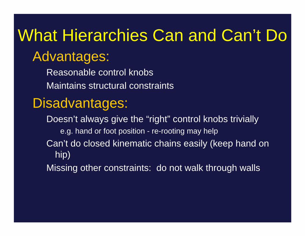
What Hierarchies Can and Can’t DoAdvantages:
Reasonable control knobsMaintains structural constraints
Disadvantages:Doesn’t always give the “right” control knobs trivially
e.g. hand or foot position - re-rooting may help
Can’t do closed kinematic chains easily (keep hand on hip)
Missing other constraints: do not walk through walls

So What Have We Done?Forward Kinematics
Given the model and the joint angles, where is the end effector? Compute this so you know where to draw primitives
Inverse KinematicsGiven a desired location of the end effector, what are the
required joint angles to put it there? Required to place the end effector near to an object in the real world.
Kinematics is easy, IK is hard because of redundancy.

Kinematics and Orientations
• Hierarchies• Forward Kinematics• Transformations (review) • Euler angles• Quaternions• Washing out yaw
for assignment 2


Interpolation
Trivial for translation: t=k * t1 + (1-k) * t2Easy for rotation in 1DNot so easy for 3D rotation


Gimbal Lock
Gimbal
y
zx
A Gimbal is a hardware implementation of Euler angles (used for mounting gyroscopes, expensive globes)
Gimbal lock is a basic problem with representing 3-D rotations using Euler angles
y
zx
Locked Gimbal


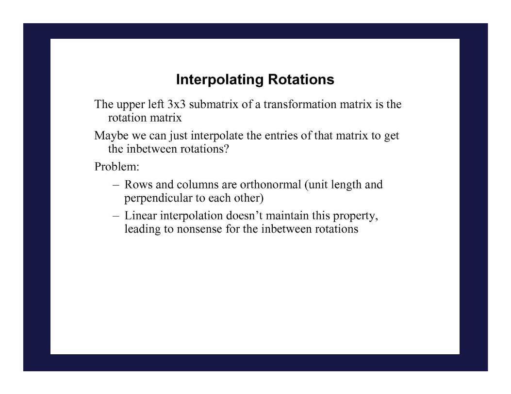
Interpolating Rotations
• Q: What kind of a compound rotation do you get by successively turning about each of the three axes of the rotation at a constant rate?
• A: not the one you want.


2-angle (θ-φ) rotation(unit sphere)
Interpolating rotations means moving on n-D sphere
Quaternion InterpolationWe can think of rotations as lying on an n-D unit sphere
1-angle (θ) rotation(unit circle)
θ1
θ2

2-angle (θ-φ) rotation(unit sphere)


Washing out Yaw
Amc file format in Euler anglesYou want roll and pitch + delta yaw not roll, pitch,
yawConvert to yaw, roll, pitch Euler angles
http://vered.rose.utoronto.ca/people/david_dir/GEMS/GEMS.html
Compute delta yaw between framesRe-animate by incrementing yaw by delta yaw.
Compute new rotation matrix.Compute delta x,z and increment to animate
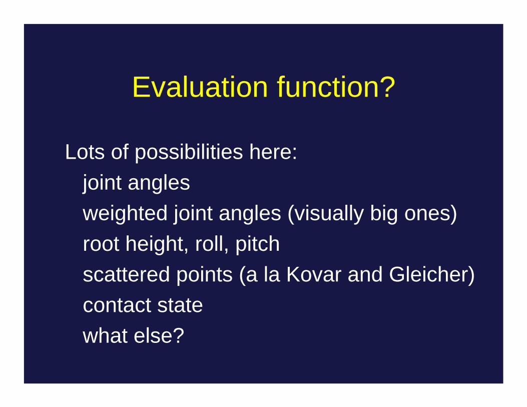
Evaluation function?
Lots of possibilities here:joint anglesweighted joint angles (visually big ones)root height, roll, pitchscattered points (a la Kovar and Gleicher)contact statewhat else?


![KINEMATICS - new.excellencia.co.innew.excellencia.co.in/college/web/pdf/Kinematics-merged.pdf · KINEMATICS KINEMATICS WORKSHEET 1 1) Displacement is a _____ [ ] 1) Vector quantity](https://img.pdfslide.net/doc/110x75/5f356d4687229051801abace/kinematics-new-kinematics-kinematics-worksheet-1-1-displacement-is-a-.jpg)