Embed Size (px)
Citation preview
KINEMATICS OF MECHANISMSKINEMATICS OF MECHANISMS(BDC 4043)
Lecture Module 1: Introduction to Mechanisms and Kinematics
Waluyo Adi SiswantoUniversiti Tun Hussein Onn Malaysia
This module is licensed under a Creative Commons Attribution 3.0 License.

INTRODUCTIONINTRODUCTION
Lecture Module 1 BDC4043 3
Course Objectives
This course is designed to introduce the concept and techniques motion machine.
The concept and techniques will help the students to integrate aspects of the theory in the study kinematics mechanisms with practical application.
Lecture Module 1 BDC4043 4
Learning Outcomes
➢ explain the shift, velocity and acceleration of various mechanism components during movement (A3, LO4)
➢ construct the mechanism based on movement components that are likely to occur in the system (C5, LO1)
➢ reproduce a graphical and analytical for cam movement (P3, LO3)
➢ analyze the characteristics of various types of gear; spur gear, helix gear, oblique gear and worm gear (C4, LO1)
At the end of this course, the students will be able to:
Lecture Module 1 BDC4043 5
References
1. Ballaney, P. L. (2003) Theory of Machines and Mechanisms, Delhi: Khanna Publishers. Call Number TJ145 .B35.
2. Uicker J.J. Gordon R.P. J.E.Shigley, (2003) Theory of Machines and Mechanisms, 3rd Edition, New York: Oxford University. Call Number TJ145 .U43.
3. D.H.Myszka, (2005) Machines and Mechanisms: Applied Kinematics Analysis, Pearson. Call Number TJ175 .M97.
4. Robert L Mott, (2006) Machine Elements in Mechanical Design 4th ed, Pearson. Call Number TJ230 .M67.
5. Rattan, S.S., (2009) Theory of Machines, 3rd edition, Tata Mc Graw Hill, New Delhi. Call Number TJ170 .R37.
Lecture Module 1 BDC4043 6
Software
1. Working Model 2D (http://www.design-simulation.com/WM2D/index.php)2. SymWise 4D (http://www.design-simulation.com/SimWise4D/index.php) 2. Universal Mechanism (http://www.universalmechanism.com)3. Adams (http://www.mscsoftware.com/product/adams)4. SAM (http://www.artas.nl/en)4. Impact (http://www.impact-fem.org)5. SMath (http://en.smath.info)6. SolidWorks (http://www.solidworks.com)7. Catia (http://www.3ds.com)8. Software Integration (http://www.softintegration.com)
Lecture Module 1 BDC4043 7
Course Delivery
LecturingExplaining theories, methods and understanding related to the topics.
TutoringDiscussing sample problems related to the topics

Lecture Module 1 BDC4043 8
Assessment Scheme
Students attendance * Quiz /Assignment (10%) Project (10%) Test (T1: 15% T2: 15%) Final Examination (50%)
* Attendance must not less than 80%
Lecture Module 1 BDC4043 9
Part 1 (7 weeks)
1) Introduction to mechanisms and Kinematics
2) Basic Principles of Movements 3) Analysis of Position and Displacement4) Analysis of Velocity
Lecture Module 1 BDC4043 10
Part 2 (7 weeks)
5) Analysis of Acceleration6) Links7) Cams8) Gears
Lecture Module 1 BDC4043 11
Time schedules
Lecture Module 1 BDC4043 12
LECTURE LECTURE CONTENTSCONTENTS
Lecture Module 1 BDC4043 13
➔ Mechanism➔ Kinematics➔ Mechanism Terminology➔ Kinematics Diagram➔ Kinematics Inversion➔ Four-Bar➔ Slide Link -Crank
Lecture Module 1 BDC4043 14
Mechanism, Kinematics
MachinesMachines are devices used to alter, transmit and direct forces to accomplisha specific objective.
A mechanismmechanism is the mechanical portion of a machine that has the function Of transferring motion and forces from a power source to an output. So, the mechanism is the hearth of a machine.
KinematicsKinematics deals with the way thins move.It is the study of the geometry of motion. Kinematic analysis involves determinationof position, displacement, rotation, speed, velocity and acceleration.
Lecture Module 1 BDC4043 15
Mechanism terminology
MechanismsMechanisms consist of connecting parts with the objective of producing desired motion.
A linkagelinkage is a mechanism where all parts are connected together to form a closed chain.LinksLinks are individual parts of mechanism. They are considered as rigid bodies. A rigidBody, hypothetically, does not change shape during motion.
One part is designated as the frameframe because it served as the frame or reference for themotion of all other parts.
A jointjoint is a movable connection between links and allows relative motion between links.There are two types of joints: primary jointsprimary joints (full joints) and higher-order jointshigher-order joints (half joints).
There are two primary joints. The revolute jointrevolute joint (pin or hinge joint). It allows pure rotationbetween the two links that it connects. The sliding joint sliding joint (piston or prism joint). It allows linearsliding between the links that it connects.
There are two higher-order joints: CamCam and GearGear. A cam joint allows both rotational and sliding between the two links that it connects. A gear connection allows rotation and sliding between two gears as their teeth mesh.
Lecture Module 1 BDC4043 16
Simple linkSimple link is a rigid body that contains only two joints, which connect it to other links.A crankcrank is a simple link that is able to complete a full rotation about a fixed center.A rockerrocker is a simple link that oscillates through an angle, reversing its direction atcertain intervals.
A complex linkcomplex link is a rigid body that contains more than two joints
A point of interest point of interest is a point on a link where the motion is of special interest. Once thekinematic analysis is performed, the displacement, velocity and acceleration of that pointare determined.
Lecture Module 1 BDC4043 17
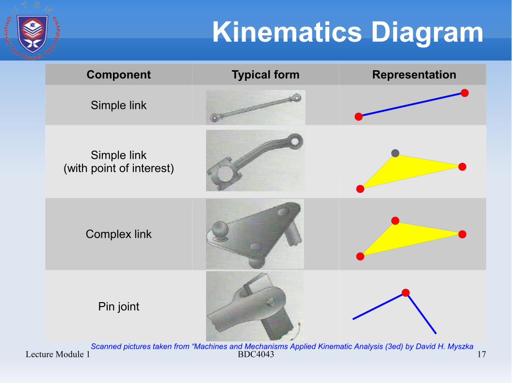
Kinematics DiagramComponent Typical form Representation
Simple link
Simple link(with point of interest)
Complex link
Pin joint
Scanned pictures taken from “Machines and Mechanisms Applied Kinematic Analysis (3ed) by David H. Myszka
Lecture Module 1 BDC4043 18
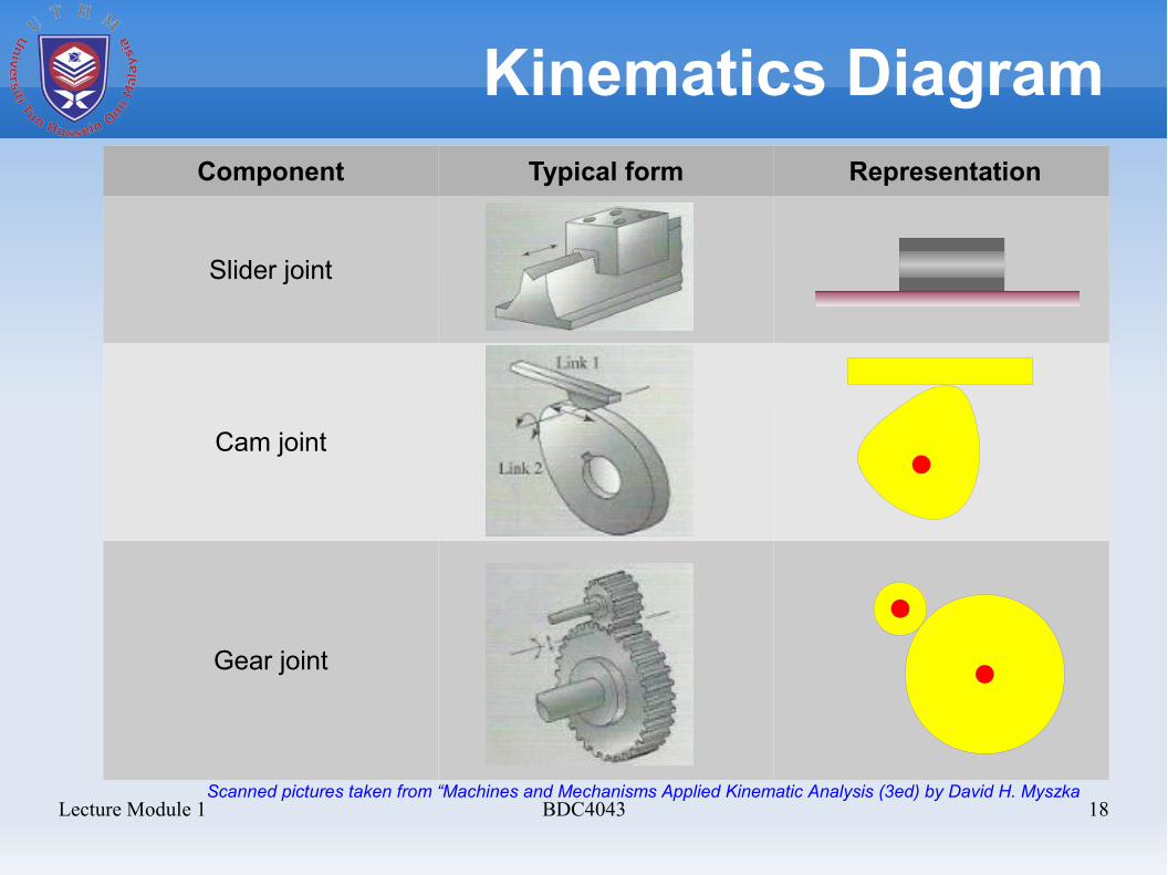
Kinematics DiagramComponent Typical form Representation
Slider joint
Cam joint
Gear joint
Scanned pictures taken from “Machines and Mechanisms Applied Kinematic Analysis (3ed) by David H. Myszka
Lecture Module 1 BDC4043 19
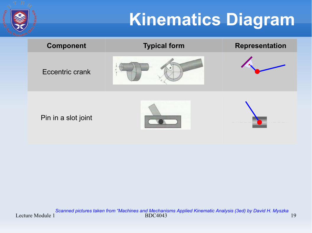
Kinematics DiagramComponent Typical form Representation
Eccentric crank
Pin in a slot joint
Scanned pictures taken from “Machines and Mechanisms Applied Kinematic Analysis (3ed) by David H. Myszka
Lecture Module 1 BDC4043 20
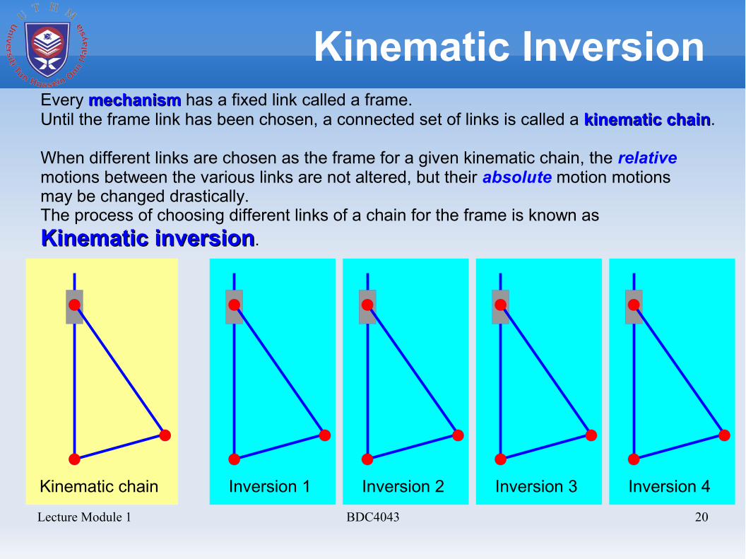
Kinematic InversionEvery mechanismmechanism has a fixed link called a frame. Until the frame link has been chosen, a connected set of links is called a kinematic chainkinematic chain.
When different links are chosen as the frame for a given kinematic chain, the relativemotions between the various links are not altered, but their absolute motion motionsmay be changed drastically. The process of choosing different links of a chain for the frame is known asKinematic inversionKinematic inversion.
Kinematic chain Inversion 1 Inversion 2 Inversion 3 Inversion 4
Lecture Module 1 BDC4043 21
Basic Mechanism
Most mechanisms have basic mechanism motion from:
➢ Four-bar mechanism➢ Crank-slider mechanism
Lecture Module 1 BDC4043 22
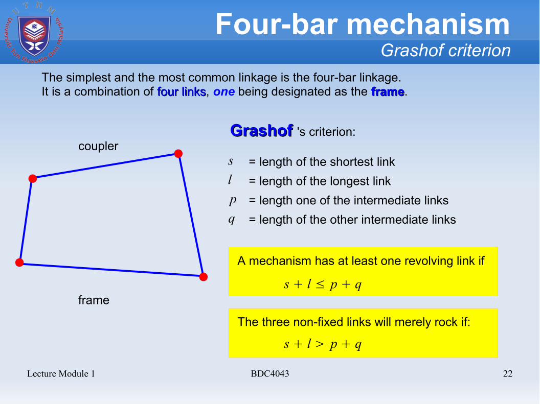
Four-bar mechanismGrashof criterion
The simplest and the most common linkage is the four-bar linkage.It is a combination of four links four links, one being designated as the frameframe.
Grashof Grashof 's criterion:
slpq
= length of the shortest link= length of the longest link= length one of the intermediate links= length of the other intermediate links
s + l ≤ p + q
A mechanism has at least one revolving link if
The three non-fixed links will merely rock if:
s + l > p + q
frame
coupler
Lecture Module 1 BDC4043 23
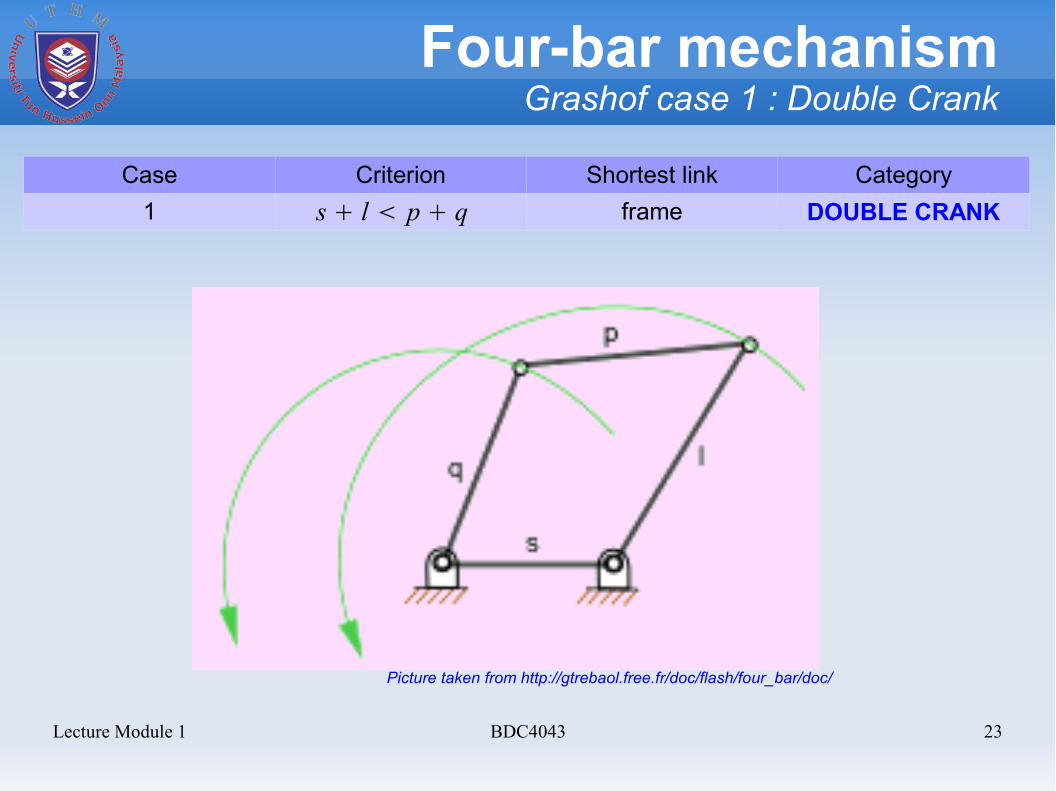
Four-bar mechanismGrashof case 1 : Double Crank
Case Criterion Shortest link Category1 frame DOUBLE CRANKs + l < p + q
Picture taken from http://gtrebaol.free.fr/doc/flash/four_bar/doc/
Lecture Module 1 BDC4043 24
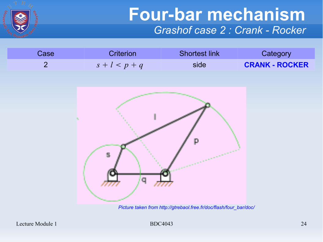
Four-bar mechanismGrashof case 2 : Crank - Rocker
Case Criterion Shortest link Category2 side CRANK - ROCKERs + l < p + q
Picture taken from http://gtrebaol.free.fr/doc/flash/four_bar/doc/

Lecture Module 1 BDC4043 25
Four-bar mechanismGrashof case 3 : Double Rocker
Case Criterion Shortest link Category3 coupler DOUBLE ROCKERs + l < p + q
Picture taken from http://gtrebaol.free.fr/doc/flash/four_bar/doc/
Lecture Module 1 BDC4043 26
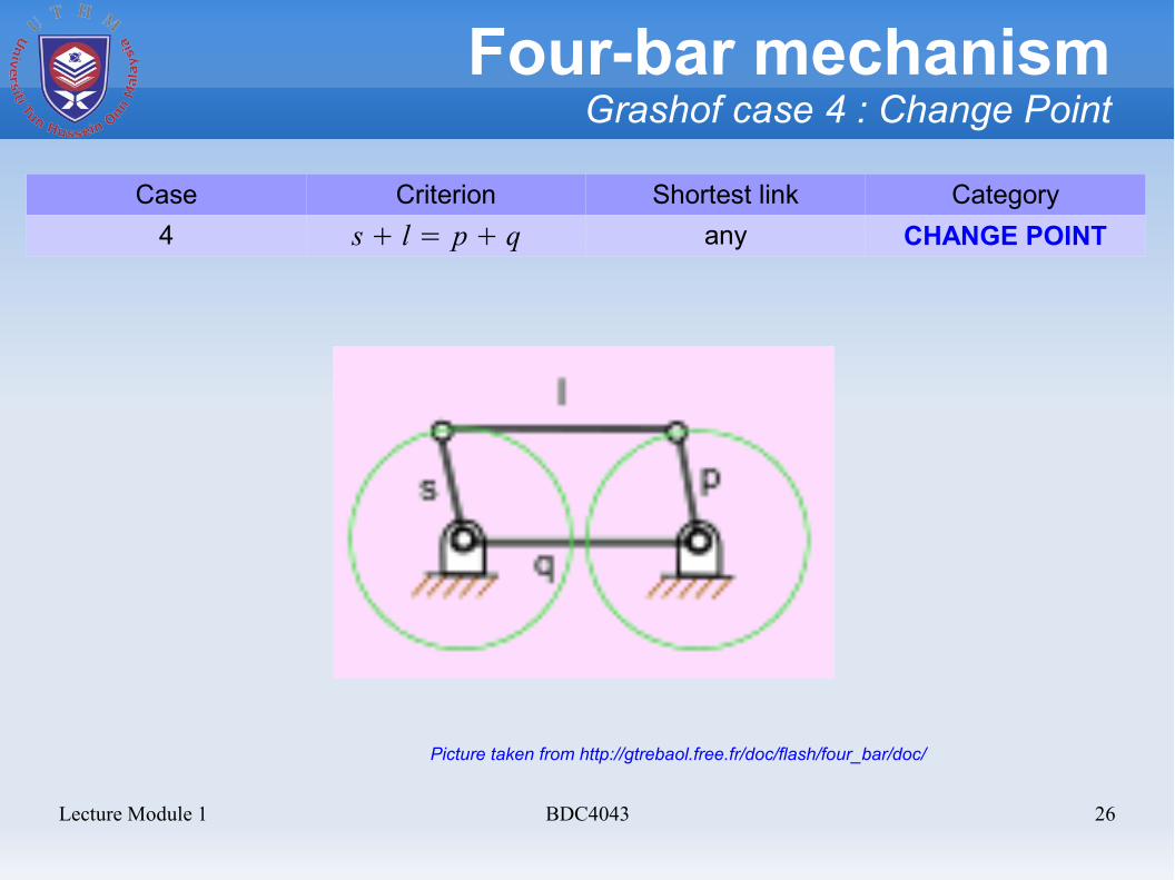
Four-bar mechanismGrashof case 4 : Change Point
Case Criterion Shortest link Category4 any CHANGE POINTs + l = p + q
Picture taken from http://gtrebaol.free.fr/doc/flash/four_bar/doc/
Lecture Module 1 BDC4043 27
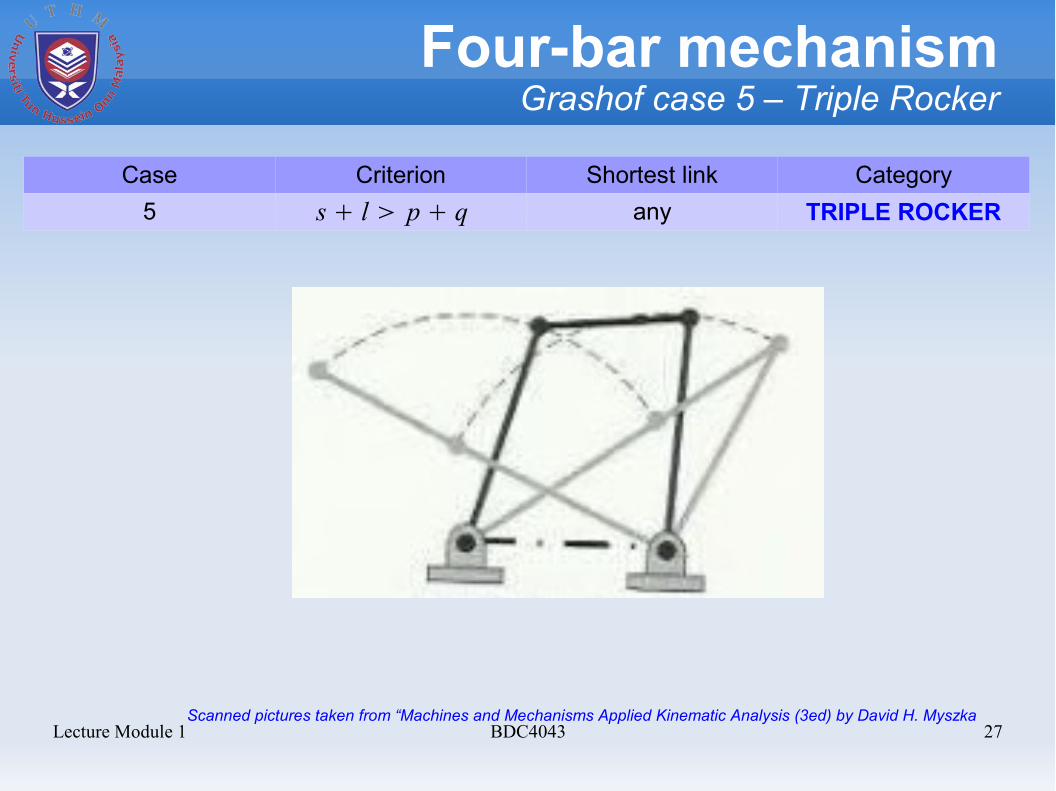
Four-bar mechanismGrashof case 5 – Triple Rocker
Case Criterion Shortest link Category5 any TRIPLE ROCKERs + l > p + q
Scanned pictures taken from “Machines and Mechanisms Applied Kinematic Analysis (3ed) by David H. Myszka
Lecture Module 1 BDC4043 28
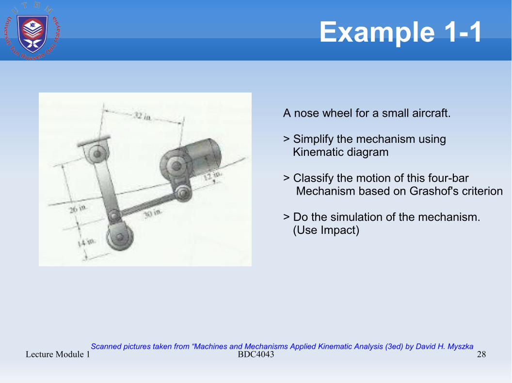
Example 1-1
A nose wheel for a small aircraft.
> Simplify the mechanism using Kinematic diagram > Classify the motion of this four-bar Mechanism based on Grashof's criterion
> Do the simulation of the mechanism. (Use Impact)
Scanned pictures taken from “Machines and Mechanisms Applied Kinematic Analysis (3ed) by David H. Myszka
Lecture Module 1 BDC4043 29
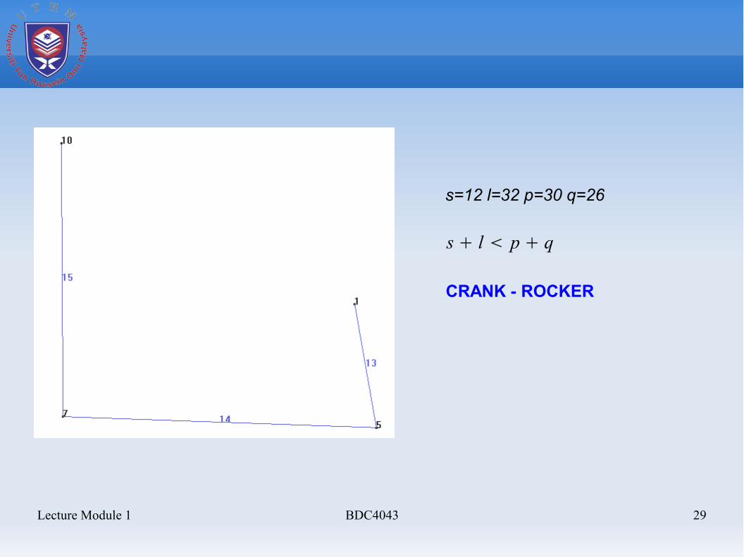
s + l < p + q
s=12 l=32 p=30 q=26
CRANK - ROCKER
Lecture Module 1 BDC4043 30
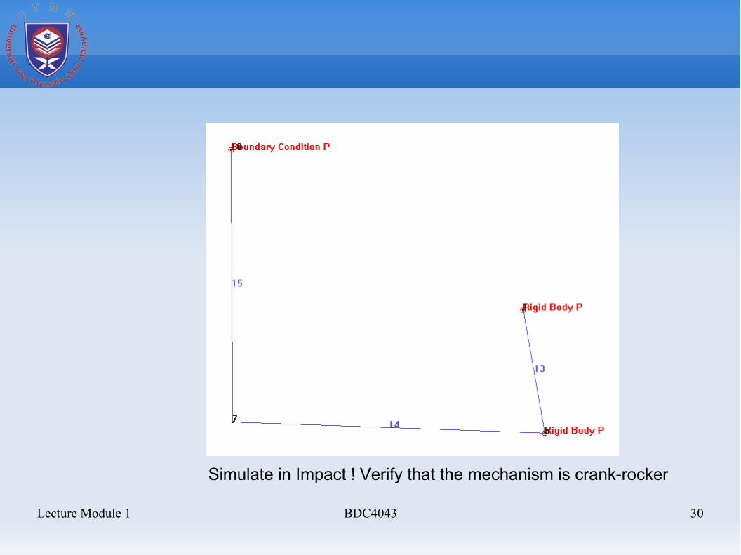
Simulate in Impact ! Verify that the mechanism is crank-rocker
Lecture Module 1 BDC4043 31
Example 1-2
Design mechanism : Case 1 to Case 5Then do the simulation in Impact
Lecture Module 1 BDC4043 32
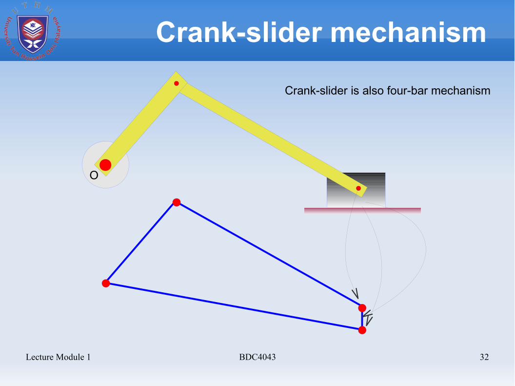
Crank-slider mechanism
O
Crank-slider is also four-bar mechanism

Lecture Module 1 BDC4043 33


![Kinematics of pantograph masts - ERNETasitava/mmt-nagaraj-1.pdf · Kinematics of pantograph masts ... extended to spatial mechanisms [7]. The main advantage of using Cartesian coordinates](https://img.pdfslide.net/doc/110x75/5ab54cf47f8b9a1a048cacd4/kinematics-of-pantograph-masts-asitavammt-nagaraj-1pdfkinematics-of-pantograph.jpg)