Embed Size (px)
Citation preview

KINETICS™ Seismic & Wind Design Manual Section D7.0
D7.0 - TABLE OF CONTENTS (Chapter D7)PAGE 1 of 1 SECTION – D7.0B
Toll Free (USA Only): 800-959-1229 RELEASED ON: 4/22/2014International: 614-889-0480FAX 614-889-0540World Wide Web: www.kineticsnoise.comE-mail: [email protected]
Dublin, Ohio, USA Cambridge, Ontario, Canada
SECTION D7.0 - TABLE OF CONTENTS
Title Section
Revision Record D7.0A
D7.0 - Piping Systems
Title Section
Seismic Forces Acting on Piping Systems D7.1
Basic Primer for Suspended Piping D7.2
Pros and Cons of Struts versus Cables D7.3
Layout Requirements for Piping Restraint Systems
Requirements for Piping System Restraints D7.4.1(Definitions and Locating Requirements)
Ceiling-Supported Pipe Restraint Arrangements D7.4.2
Floor- or Roof-Supported Pipe Restraint Arrangements D7.4.3
Vertical Pipe Run Restraint Arrangements D7.4.4
Axial Restraint of Steam Pipes D7.4.5
Piping Restraint System Attachment Details
Transferring Forces (Piping Restraints) D7.5.1
Cable Clamp Details D7.5.2
Piping Attachment Details D7.5.3
Structure Attachment Details for Piping Restraints D7.5.4
Non-Moment Generating Connections D7.5.5
Connection Options for Awkward Situations D7.6

KINETICS™ Seismic & Wind Design Manual Section D7.1
SEISMIC FORCES ACTING ON PIPING SYSTEMSPAGE 1 of 2 SECTION – D7.1
Toll Free (USA Only): 800-959-1229 RELEASED ON: 4/16/2014International: 614-889-0480FAX 614-889-0540World Wide Web: www.kineticsnoise.comE-mail: [email protected]
Dublin, Ohio, USA Cambridge, Ontario, Canada
SEISMIC FORCES ACTING ON PIPING SYSTEMSWhen subjected to an earthquake, piping systems must resist lateral and axial buckling forces,and the restraint components for these systems must resist pullout and localized structuralfailures.
Most piping systems are suspended from the deck above on either fixed or isolated hanger rodsystems. They may be supported singly or there may be several pipes attached to a commontrapeze. On some occasions the pipes may run vertically or may be mounted to the floor.
D7.1.1 Suspended Systems
Most codes do not require that piping supported on non-moment generating (swiveling) hangerrods 12 in or less in length be restrained. The 12 in length was determined based on thenatural frequency of systems supported on the short hanger rods. In practice, it has beenfound that the vibrations generated by earthquakes do not excite these types of systems and,although the pipes move back and forth somewhat as a result of an earthquake, they do nottend to oscillate severely and tear themselves apart.
There are also exclusions in most codes for small pipes, no matter what the hanger rod length.Again, the basis for this exclusion is based on the post-earthquake review of manyinstallations. It has been found that smaller pipes are light and flexible enough that theycannot generate enough energy to do significant damage to themselves.
For cases where restraints are required, however, the forces involved can be significant. Thisis due to the difference between the spacing of piping system supports and piping systemrestraints. Supports for piping systems are typically sized to carry approximately a 10 ft lengthof piping (in the case of trapezes, multiple pipes each approximately 10 ft long). Seismicrestraints, on the other hand, are normally spaced considerably further apart with the spacingvarying by restraint type, restraint capacity, pipe sizes, and the seismic design load. It is veryimportant to be aware of the impact of the difference in spacing as the wider this spacing, thelarger the seismic load when compared to the support load. Guidance in determining restraintspacing requirements is available in Chapter D4 of this manual.
To illustrate this difference, consider a simple example of a single pipe weighing 50 lb/ft beingrestrained against a 0.2g seismic force with restraints located on 80 ft centers and supportslocated on 10 ft centers. The load that is applied to the hanger rods by the weight of the pipeis 50 lb/ft x 10 ft or 500 lb each (assuming single rod supports). The horizontal load thatoccurs at the restraint locations is the total restrained weight (50 lb/ft x 80 ft = 4000 lb)multiplied by the seismic force (0.2g) or 800 lb. Thus the seismic load is larger than thevertical dead load.
Restraints for suspended systems are normally in the form of cables or struts that run from thepipe up to the deck at an angle. Because of the angle, horizontal seismic loads also generate

KINETICS™ Seismic & Wind Design Manual Section D7.1
SEISMIC FORCES ACTING ON PIPING SYSTEMSPAGE 2 of 2 SECTION – D7.1
Toll Free (USA Only): 800-959-1229 RELEASED ON: 4/16/2014International: 614-889-0480FAX 614-889-0540World Wide Web: www.kineticsnoise.comE-mail: [email protected]
Dublin, Ohio, USA Cambridge, Ontario, Canada
vertical forces that must be resisted. Therefore, restraint devices must be attached at supportlocations so that there is a vertical force-resisting member available.
As the angle becomes steeper (the restraint member becomes more vertical), the verticalforces increase. At 45 degrees the vertical force equals the horizontal force and at60 degrees the vertical force is 1.73 times the horizontal force.
The net result is that for cable systems or for struts loaded in tension, the uplift force at thebottom end of the restraint can be considerably higher than the downward weight load of thepipe. Returning to our example, assume that we have a restraint member installed at a 60degree angle from horizontal and that the lateral force will load it in tension. In this case, the800 lb seismic force generates an uplift force of 1.73 x 800 lb or 1384 lb. This is 884 lb morethan the support load and, depending upon the support rod length and stiffness, can cause thesupport rod to buckle. Rod stiffeners are used to protect against this condition and sizinginformation is available in Chapter D4 of this manual.
Unlike cables, if struts are used for restraint they can also be loaded in compression. In theexample above, if the strut were loaded in compression, the 1384 lb load would be added tothe support load (trying to pry the hanger rod out of the deck). The total support capacityrequired would be 1384 lb + 500 lb or 1884 lb. As a consequence, when using struts, thehanger rod must be designed to support 1884 lb instead of the 500 lb maximum generatedwith cables. Hanger rod sizing information is also available in Chapter D4 of this manual.
D7.1.2 Riser Systems
Where piping systems are running vertically in structures, except for the loads directly appliedby vertical seismic load components identified in the code, there will be little variation in verticalforces from the static condition. Lateral loads are normally addressed by pipe guides and thespacing between pipe guides is not to exceed the maximum tabulated lateral restraint spacingindicated in the design tables in Chapter D4.
D7.1.3 Floor-Mounted Systems
The primary difference between floor- and ceiling-mounted piping systems is that the supportloads in the pipe support structure are in compression instead of tension (as in the hangerrods). Although a support column and diagonal cables can be used, a fixed stand made ofangle or strut is generally preferred. Rules relating to restraint spacing and the sizinginformation for diagonal struts are the same as for hanging applications.
However, the support legs need to be designed to support the combined weight and verticalseismic load (for a two-legged stand and the example above, 500 lb / 2 + 1384 lb or 1634 lb) incompression (Note: 500 lb / 2 is the load per leg for two legs). The anchorage for the legsneeds to be able to withstand the difference between the dead weight and the vertical seismicload (in the example above 1384 lb - 500 lb / 2 or 1134 lb).

KINETICS™ Seismic & Wind Design Manual Section D7.2
BASIC PRIMER FOR SUSPENDED PIPINGPAGE 1 of 2 SECTION – D7.2
Toll Free (USA Only): 800-959-1229 RELEASED ON: 4/18/2014International: 614-889-0480FAX 614-889-0540World Wide Web: www.kineticsnoise.comE-mail: [email protected]
Dublin, Ohio, USA Cambridge, Ontario, Canada
BASIC PRIMER FOR SUSPENDED PIPINGFailures in piping systems resulting from earthquakes have historically resulted in largequantities of water or other materials being dumped into occupied spaces of the buildingstructure. The resulting dollar damage to the building and its contents is often considerablymore than the costs of damage to the building structure itself. In addition, failure of thebuilding’s mechanical systems can render the structure unfit for occupation until the damage iscorrected, and result in major problems for the tenants and/or owners.
Because of the impact that failures of these systems have had in the past, designrequirements for piping systems have become much more stringent.
Within a building structure, there are multitudes of different kinds of piping systems, each withits own function and requirements. These include potable water, sanitary, HVAC, fire piping,fuel, gas, medical gases, and process systems to name a few. Requirements for the systemsvary based on the criticality or hazardous nature of the transported fluid. Code mandatedrequirements for the restraint of piping systems are addressed in Chapter D2 of this manual(Seismic Building Code Review).
Prior to applying this section of the manual, it is assumed that the reader has reviewedChapter D2 and has determined that there is indeed a requirement for the restraint ofpiping. This chapter of the manual is a “how to” guide and will deal only with theproper installation and orientation of restraints and not whether or not they are requiredby code or by specification.
This chapter also does not address the sizing of restraint hardware. Chapter D4includes sections on sizing componentry based on the design seismic force and theweight of the system being restrained.
Process piping is not directly associated with building operating systems and often has its ownset of requirements. If there are no applicable special requirements, these systems should berestrained in a similar fashion to the building mechanical systems. This manual will notaddress any special requirements for process piping systems.
Building mechanical systems (potable water, HVAC, sanitary) can normally be groupedtogether and have similar design requirements. In many cases, requirements for fuel, gas, andmedical gasses are more stringent. Refer to the code review chapter (D2) of the manual forapplicable design requirements.
Fire piping restraint is normally addressed in the applicable fire code. There is always somerequirement for restraint, as triggering a nozzle generates thrust in the piping and must becountered. This thrust may be unidirectional, unlike the loads generated by an earthquake,and can sometimes be countered by unsymmetrical restraint arrangements.

KINETICS™ Seismic & Wind Design Manual Section D7.2
BASIC PRIMER FOR SUSPENDED PIPINGPAGE 2 of 2 SECTION – D7.2
Toll Free (USA Only): 800-959-1229 RELEASED ON: 4/18/2014International: 614-889-0480FAX 614-889-0540World Wide Web: www.kineticsnoise.comE-mail: [email protected]
Dublin, Ohio, USA Cambridge, Ontario, Canada
These types of non-seismic restraints are not addressed in this chapter. To determine thedesign requirements for seismic applications, refer again back to the code review Chapter D2.
In many cases, piping can be excluded from restraint if it is small enough in size or mounted inclose proximity to the ceiling structure. When applying this exemption, current codes requirethe installation of a “non-moment generating connection” at the top anchorage point. This termis often confusing and deserves further clarification. A “non-moment generating connection” isone that will allow the supported pipe to swing freely in any direction if acted on by an outsideforce. Some examples of “non-moment generating connections” are illustrated below.
Figure D7.2-1; Non-moment generating connections

KINETICS™ Seismic & Wind Design Manual Section D7.3
PROS AND CONS OF STRUTS VERSUS CABLESPAGE 1 of 4 SECTION – D7.3
Toll Free (USA Only): 800-959-1229 RELEASED ON: 4/23/2014International: 614-889-0480FAX 614-889-0540World Wide Web: www.kineticsnoise.comE-mail: [email protected]
Dublin, Ohio, USA Cambridge, Ontario, Canada
PROS AND CONS OF STRUTS VERSUS CABLES
Both cables and struts have their place in the restraint of piping. In order to minimize costsand speed up installation, the differences between the two should be understood.
In general, piping restrained by struts will require only 1 brace per restraint location whilepiping restrained with cables requires that 2 cables be fitted forming an “X” or a “V”. As atrade-off, the number of restraint points needed on a given run of piping will typically beconsiderably higher for a strut-restrained system than for the cable-restrained system and,generally, strut-restrained systems will be more costly to install.
An added factor to consider when selecting a restraint system is that once a decision isreached on the type to use for a particular run, code requirements state that the same type ofsystem must be used for the entire run (all cable or all strut). Later sections in this chapter willdefine runs, but for our purposes at present, it can be considered to be a more or less straightsection of piping.
The obvious advantage to struts is that, when space is at a premium, cables angling up to theceiling on each side of a run may take more space than is available. Struts can be fitted to oneside only, allowing a more narrow packaging arrangement.
The advantages of cables, where they can be used, are numerous. First, they can usually bespaced less frequently along a pipe than can struts. Second, they cannot increase the tensileforces in the hanger rod that results from the weight load, so rod and rod anchorage capacitiesare not impacted. Third, they are easily set to the proper length. And fourth, they are wellsuited to isolated piping applications.
To better explain the differences between the systems, it is necessary to look at how seismicforces are resisted with cables and struts. Shown below are sketches of both cable-restrainedand strut-restrained piping.
Figure D7.3-1; Cable Restrained

KINETICS™ Seismic & Wind Design Manual Section D7.3
PROS AND CONS OF STRUTS VERSUS CABLESPAGE 2 of 4 SECTION – D7.3
Toll Free (USA Only): 800-959-1229 RELEASED ON: 4/23/2014International: 614-889-0480FAX 614-889-0540World Wide Web: www.kineticsnoise.comE-mail: [email protected]
Dublin, Ohio, USA Cambridge, Ontario, Canada
Figure D7.3-2; Strut Restrained
The key factor to note is that cables can only be loaded in tension. This means that seismicforces can only generate compressive loads in the pipe hanger rod. Seismic forces can,however, load the strut in compression resulting in a tensile load on the hanger rod.
This tensile load is in addition to any deadweight load that may already be supported by thehanger and is often significantly higher than the original load. This has the potential to rip thehanger rod out of the support structure and must be considered when sizing components.
Because of this added tensile component and the resulting impact on the necessary hangerrod size, most strut manufacturers limit the maximum allowable strut angle (to the horizontal)to 45 degrees. This is lower than typical allowable angles for cables that often reach 60degrees from the horizontal. Although the data provided in Section D4.4 of this manual allowthe use of higher angles for strut systems, users will find that the penalties in hanger rod sizeand anchorage will likely make these higher angles unusable in practice. To put this intocontext, examples will be provided at both 45 degrees and 60 degrees from the vertical toindicate the impact on capacity that results from the angle.
For a 45 degree restraint angle, if we assume a trapeze installation with the weight (W) equallysplit between 2 supports, the initial tension in each support is 0.5*W. Using a 0.25g lateraldesign force (low seismic area), the total tensile load in a hanger increases to 0.75*W forbracing on every support and 1.0W for bracing on every other support, if a strut is used.
For reference, if struts are used in a 60 degree angle configuration (from the horizontal), thetensile force in the hanger rod for all cases increases by a factor of 1.73 (tan 60) over thatlisted in the previous paragraph. This means that the tensile force becomes .94*W for bracingon every support and 1.36*W for bracing on every other support.
On the other hand, where 0.25g is applicable, buckling concerns in the pipe are such that thespacing between lateral restraints can be as high as 40 ft and for axial restraints, 80 ft. If wewere to try to use struts placed at a 40 ft spacing in conjunction with supports spaced at 10 ft,the tensile force developed by a seismic event in the rod increases to 1.5*W for 45 degreeconfigurations and to 2.23*W for 60 degree configurations.
KINETICS™ Seismic & Wind Design Manual Section D7.3
PROS AND CONS OF STRUTS VERSUS CABLESPAGE 3 of 4 SECTION – D7.3
Toll Free (USA Only): 800-959-1229 RELEASED ON: 4/23/2014International: 614-889-0480FAX 614-889-0540World Wide Web: www.kineticsnoise.comE-mail: [email protected]
Dublin, Ohio, USA Cambridge, Ontario, Canada
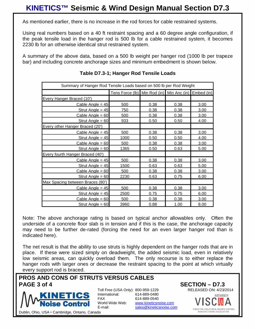
As mentioned earlier, there is no increase in the rod forces for cable restrained systems.
Using real numbers based on a 40 ft restraint spacing and a 60 degree angle configuration, ifthe peak tensile load in the hanger rod is 500 lb for a cable restrained system, it becomes2230 lb for an otherwise identical strut restrained system.
A summary of the above data, based on a 500 lb weight per hanger rod (1000 lb per trapezebar) and including concrete anchorage sizes and minimum embedment is shown below.
Table D7.3-1; Hanger Rod Tensile Loads
Summary of Hanger Rod Tensile Loads based on 500 lb per Rod Weight
Tens Force (lb) Min Rod (in) Min Anc (in) Embed (in)Every Hanger Braced (10')
Cable Angle = 45 500 0.38 0.38 3.00Strut Angle = 45 750 0.38 0.38 3.00
Cable Angle = 60 500 0.38 0.38 3.00Strut Angle = 60 933 0.50 0.50 4.00
Every other Hanger Braced (20')Cable Angle = 45 500 0.38 0.38 3.00Strut Angle = 45 1000 0.50 0.50 4.00
Cable Angle = 60 500 0.38 0.38 3.00Strut Angle = 60 1365 0.50 0.63 5.00
Every fourth Hanger Braced (40')Cable Angle = 45 500 0.38 0.38 3.00Strut Angle = 45 1500 0.63 0.63 5.00
Cable Angle = 60 500 0.38 0.38 3.00Strut Angle = 60 2230 0.63 0.75 6.00
Max Spacing between Braces (80')Cable Angle = 45 500 0.38 0.38 3.00Strut Angle = 45 2500 0.75 0.75 6.00
Cable Angle = 60 500 0.38 0.38 3.00Strut Angle = 60 3960 0.88 1.00 8.00
Note: The above anchorage rating is based on typical anchor allowables only. Often theunderside of a concrete floor slab is in tension and if this is the case, the anchorage capacitymay need to be further de-rated (forcing the need for an even larger hanger rod than isindicated here).
The net result is that the ability to use struts is highly dependent on the hanger rods that are inplace. If these were sized simply on deadweight, the added seismic load, even in relativelylow seismic areas, can quickly overload them. The only recourse is to either replace thehanger rods with larger ones or decrease the restraint spacing to the point at which virtuallyevery support rod is braced.

KINETICS™ Seismic & Wind Design Manual Section D7.3
PROS AND CONS OF STRUTS VERSUS CABLESPAGE 4 of 4 SECTION – D7.3
Toll Free (USA Only): 800-959-1229 RELEASED ON: 4/23/2014International: 614-889-0480FAX 614-889-0540World Wide Web: www.kineticsnoise.comE-mail: [email protected]
Dublin, Ohio, USA Cambridge, Ontario, Canada
It should also be noted that the hanger rods in tension become seismic elements. This occurswith struts, but does not with cables. As a result, the system must comply with all of theanchor requirements specified by ICC. This includes the use of seismically rated anchors andembedment depths that are in conformance with ICC requirement for those types of anchors.With larger anchor sizes, floor slab thickness may cause this to become a significant problem.
With both cables and struts, the hanger rods can be loaded in compression. As the seismicforce increases, it eventually overcomes the force of gravity and produces a buckling load inthe hanger rod. It is mandatory in all cases that the rod be able to resist this force.
There is a wide range of variables involved in determining the need for rod stiffeners to resistthis buckling load. Factors that impact this include 1) the magnitude of the compressive force,2) the weight load carried by the hanger rod, 3) the length of the hanger rod, 4) the diameter ofthe hanger rod, and 5) the angle between the restraint strut or cable and the horizontal axis.
Charts are included in Section D4.4 of this manual that allow the user to determine if there is aneed for a stiffener and to allow the proper selection if required.
Because uplift occurs, some attention must be given to isolated systems. First, when usingisolators, the location of the isolation element needs to be at the top end of the hanger rod(close to, but not tight against the ceiling). If placed at the middle of the hanger rod, therod/isolator combination will have virtually no resistance to bending and will quickly buckleunder an uplift load.
Second, a limit stop must be fit to the hanger rod, just beneath the hanger such that when therod is pushed upward a rigid connection is made between the hanger housing and the hangerrod that prevents upward motion. This is accomplished by adding a washer and nut to thehanger rod just below the isolator (see the sketch below).
Figure D7.3-3; Installation for an Isolation Hanger in a Seismic Application
KINETICS™ Seismic & Wind Design Manual Section D7.4.1
PIPE RESTRAINTS-DEFINITIONS AND LOCATING REQUIREMENTSPAGE 1 of 7 SECTION – D7.4.1
Toll Free (USA Only): 800-959-1229 RELEASED ON: 4/18/2014International: 614-889-0480FAX 614-889-0540World Wide Web: www.kineticsnoise.comE-mail: [email protected]
Dublin, Ohio, USA Cambridge, Ontario, Canada
PIPE RESTRAINTS-DEFINITIONS AND LOCATING REQUIREMENTS
There are a number of design guides that have been developed over the years but the onewith the longest history and most widely accepted is SMACNA. They have developed ahandbook that offers conservative guidance that an end user can reference in selecting andinstalling restraints for distribution systems. While the information provided in that handbook isgood, it suffers from a couple of inherent drawbacks. The first is that because it is linked togenerically available hardware, the ratings that are assumed for the various hardwarecomponents are the lowest of any of the many possibilities available in the marketplace. Thenet result is that the suggested hardware is larger in general than that which could be used ifhigher quality componentry it specified. The second is that their presentation of the results isextremely cumbersome and difficult to use.
While the criteria presented in this document is based on the guidance offered by SMACNA, ithas been possible to increase the component ratings as the actual capacity, type andmanufacture of these components is clearly known. In addition, based on a critical review ofthe data presentation in the SMACNA handbook, it has been possible to greatly simplify themethod of selection making the end result much simpler to use.
With respect to the conceptual restraint arrangement illustrations, the SMACNA concepts areappropriate and are referenced here.
In general, pipes are restrained in lengths called “runs.” Therefore before getting into adetailed review of the restraint systems it is imperative that a definition of “run” as well as otherkey terms be addressed.
D7.4.1-1; Definitions
Axial In the direction of the axis of the pipe.
Lateral Side to side when looking along the axis of the pipe.
Pipe Clamp A heavy duty split ring clamp tightened against the pipe to the point that it can beused to control the axial motion of the pipe.
Restraint Any device that limits the motion of a pipe in either the lateral or axial direction.
Run A more or less straight length of pipe where offsets are limited to not more than S/16where S is the maximum permitted lateral restraint spacing (a function of pipe size and seismicforces) and the total length is greater than S/2. (Note: S dimensions for various conditions arelisted in Chapter D4.)

KINETICS™ Seismic & Wind Design Manual Section D7.4.1
PIPE RESTRAINTS-DEFINITIONS AND LOCATING REQUIREMENTSPAGE 2 of 7 SECTION – D7.4.1
Toll Free (USA Only): 800-959-1229 RELEASED ON: 4/18/2014International: 614-889-0480FAX 614-889-0540World Wide Web: www.kineticsnoise.comE-mail: [email protected]
Dublin, Ohio, USA Cambridge, Ontario, Canada
Figure D7.4.1-1; Definition of a “Run” of Pipe
Short Run A run as defined above where the total length is less than S/2 and where it isconnected on both ends to other runs or short runs.
Drop A length of pipe that normally extends down from an overhead run of pipe and connectsto a piece of equipment, usually through some type of flex connector. The drop can alsoextend horizontally. In order to qualify as a drop, the length of this pipe must be less than S/2.If over S/2, the length of pipe would be classified as a run.
Figure D7.4.1-2; Definition of a “Drop”

KINETICS™ Seismic & Wind Design Manual Section D7.4.1
PIPE RESTRAINTS-DEFINITIONS AND LOCATING REQUIREMENTSPAGE 3 of 7 SECTION – D7.4.1
Toll Free (USA Only): 800-959-1229 RELEASED ON: 4/18/2014International: 614-889-0480FAX 614-889-0540World Wide Web: www.kineticsnoise.comE-mail: [email protected]
Dublin, Ohio, USA Cambridge, Ontario, Canada
D7.4.1-2; Restraint Requirements
1) Full runs (Greater in length than S/2) must be restrained in both the axial and lateraldirection. If the run is not a short run or a drop, it must, as a minimum, be laterally restrainedat the last support location on each end.
Figure D7.4.1-2; Basic Restraint Requirements for a Typical “Run” of Pipe
2) If a run is longer than “S”, intermediate restraints are required to limit the spacing to thatpermitted by the building code (see table in Chapter D4).
Figure D7.4.1-3; Basic Restraint Requirements for a Long “Run” of Pipe
3) Axial restraints attached to the run of piping along its length must be connected using a pipeclamp (as previously defined).
4) Short runs or drops need only have one lateral and one axial restraint.

KINETICS™ Seismic & Wind Design Manual Section D7.4.1
PIPE RESTRAINTS-DEFINITIONS AND LOCATING REQUIREMENTSPAGE 4 of 7 SECTION – D7.4.1
Toll Free (USA Only): 800-959-1229 RELEASED ON: 4/18/2014International: 614-889-0480FAX 614-889-0540World Wide Web: www.kineticsnoise.comE-mail: [email protected]
Dublin, Ohio, USA Cambridge, Ontario, Canada
Figure D7.4.1-4; Basic Restraint Requirements for Multiple Short “Runs” of Pipe
5) If a lateral restraint is located within 2 feet of a corner (based on a measurement to the pipecenterline), it can be used as an axial restraint on the intersecting run.
Figure D7.4.1-5; “Double Duty” for Corner Restraints
6) Larger pipes cannot be restrained with restraints located on smaller branch lines.

KINETICS™ Seismic & Wind Design Manual Section D7.4.1
PIPE RESTRAINTS-DEFINITIONS AND LOCATING REQUIREMENTSPAGE 5 of 7 SECTION – D7.4.1
Toll Free (USA Only): 800-959-1229 RELEASED ON: 4/18/2014International: 614-889-0480FAX 614-889-0540World Wide Web: www.kineticsnoise.comE-mail: [email protected]
Dublin, Ohio, USA Cambridge, Ontario, Canada
Figure D7.4.1-6; Do not Restrain Larger Pipes with Restraints on Smaller Ones
7) Within a run, the type of restraint used must be consistent. For example, mixing a strut withcable restraints is not permitted.
Figure D7.4.1-7; Mismatched Struts and Cable Restraints
KINETICS™ Seismic & Wind Design Manual Section D7.4.1
PIPE RESTRAINTS-DEFINITIONS AND LOCATING REQUIREMENTSPAGE 6 of 7 SECTION – D7.4.1
Toll Free (USA Only): 800-959-1229 RELEASED ON: 4/18/2014International: 614-889-0480FAX 614-889-0540World Wide Web: www.kineticsnoise.comE-mail: [email protected]
Dublin, Ohio, USA Cambridge, Ontario, Canada
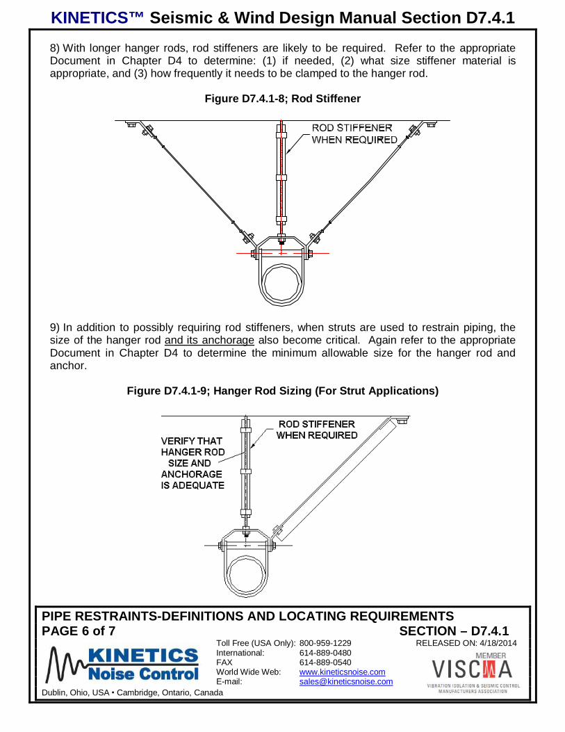
8) With longer hanger rods, rod stiffeners are likely to be required. Refer to the appropriateDocument in Chapter D4 to determine: (1) if needed, (2) what size stiffener material isappropriate, and (3) how frequently it needs to be clamped to the hanger rod.
Figure D7.4.1-8; Rod Stiffener
9) In addition to possibly requiring rod stiffeners, when struts are used to restrain piping, thesize of the hanger rod and its anchorage also become critical. Again refer to the appropriateDocument in Chapter D4 to determine the minimum allowable size for the hanger rod andanchor.
Figure D7.4.1-9; Hanger Rod Sizing (For Strut Applications)

KINETICS™ Seismic & Wind Design Manual Section D7.4.1
PIPE RESTRAINTS-DEFINITIONS AND LOCATING REQUIREMENTSPAGE 7 of 7 SECTION – D7.4.1
Toll Free (USA Only): 800-959-1229 RELEASED ON: 4/18/2014International: 614-889-0480FAX 614-889-0540World Wide Web: www.kineticsnoise.comE-mail: [email protected]
Dublin, Ohio, USA Cambridge, Ontario, Canada
10) In some cases, it may be possible to locate the piping system close enough to the supportstructure (12”) to eliminate the need for restraint. (Refer to the building code review chapter(D2) to determine if this exemption is applicable.) If it is applicable, the 12” dimension ismeasured as shown below. (Note also the required non-moment generating connection at thetop of the hanger rod.)
Figure D7.4.1-10; 12” Hanger Rod Exemption
11) When using the above rule it is critical that all support locations in a run conform. If evenone location exceeds 12”, the run cannot be exempted from restraint.
Figure D7.4.1-11; Run Fails the Consistency Requirement for 12” Exemption
KINETICS™ Seismic & Wind Design Manual Section D7.4.2
CEILING-SUPPORTED PIPE RESTRAINT ARRANGEMENTSPAGE 1 of 8 SECTION – D7.4.2
Toll Free (USA Only): 800-959-1229 RELEASED ON: 4/18/2014International: 614-889-0480FAX 614-889-0540World Wide Web: www.kineticsnoise.comE-mail: [email protected]
Dublin, Ohio, USA Cambridge, Ontario, Canada
CEILING-SUPPORTED PIPE RESTRAINT ARRANGEMENTS
Although the basic principle of diagonal bracing is almost always used to design restraintsystems, the actual arrangement of these systems can vary significantly. Despite what lookslike substantially different designs, the design forces in the members remain the same, and thesame rules apply when sizing components. Illustrated here are many different restraintarrangements, all of which can be used in conjunction with the design “rules” provided in thismanual.
Details of the end connections and anchorage hardware are shown in subsequent sections ofthe manual. It is assumed in this manual that the restraint component is attached to astructural element capable of resisting the design seismic load.
Due to variations in the installation conditions such as structural clearance, locations ofstructural attachment points and interference with other pieces of equipment or systems, therewill likely be significant benefits to using varying arrangements in different locations on thesame job.
The only significant caution here is that it is not permissible to mix struts and cables on thesame run.
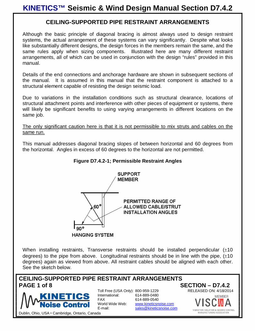
This manual addresses diagonal bracing slopes of between horizontal and 60 degrees fromthe horizontal. Angles in excess of 60 degrees to the horizontal are not permitted.
Figure D7.4.2-1; Permissible Restraint Angles
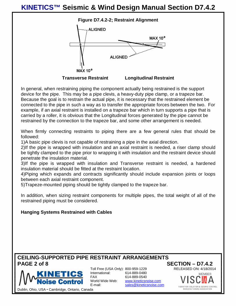
When installing restraints, Transverse restraints should be installed perpendicular ( 10degrees) to the pipe from above. Longitudinal restraints should be in line with the pipe, ( 10degrees) again as viewed from above. All restraint cables should be aligned with each other.See the sketch below.
KINETICS™ Seismic & Wind Design Manual Section D7.4.2
CEILING-SUPPORTED PIPE RESTRAINT ARRANGEMENTSPAGE 2 of 8 SECTION – D7.4.2
Toll Free (USA Only): 800-959-1229 RELEASED ON: 4/18/2014International: 614-889-0480FAX 614-889-0540World Wide Web: www.kineticsnoise.comE-mail: [email protected]
Dublin, Ohio, USA Cambridge, Ontario, Canada
Figure D7.4.2-2; Restraint Alignment
Transverse Restraint Longitudinal Restraint
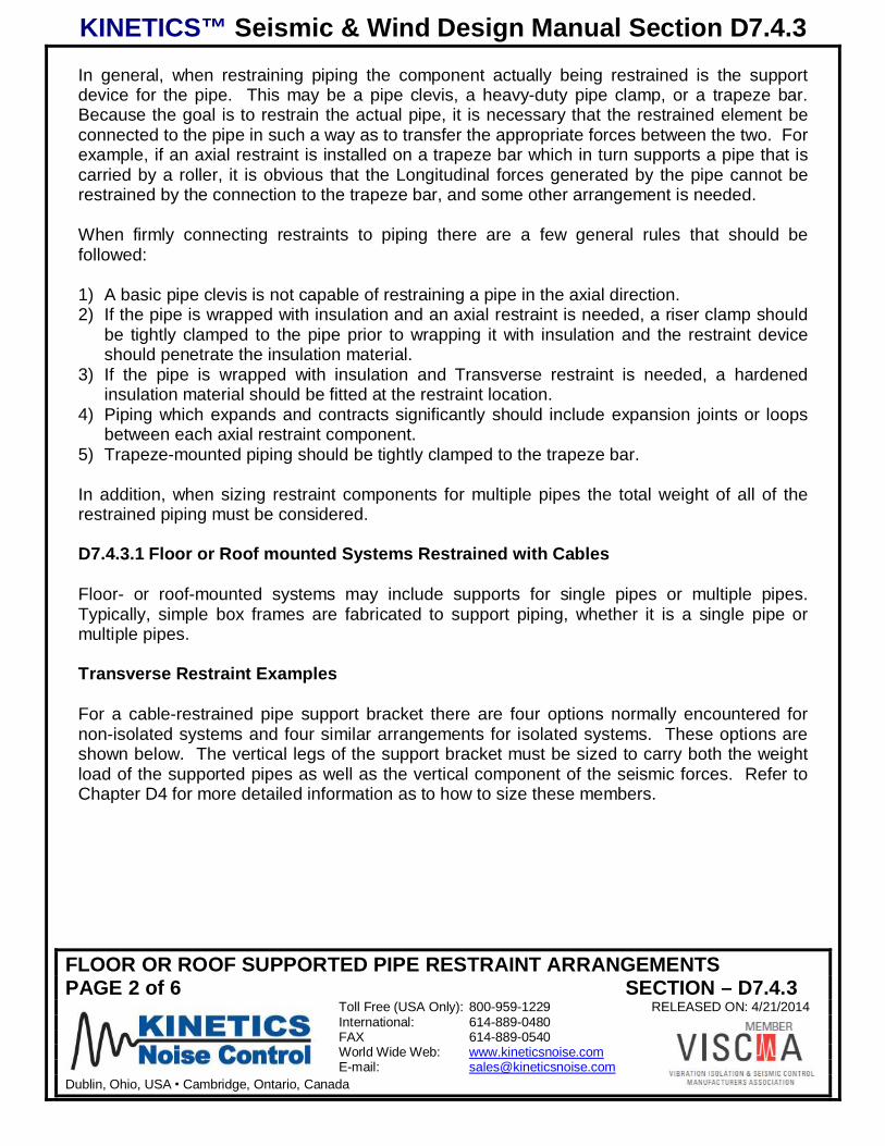
In general, when restraining piping the component actually being restrained is the supportdevice for the pipe. This may be a pipe clevis, a heavy-duty pipe clamp, or a trapeze bar.Because the goal is to restrain the actual pipe, it is necessary that the restrained element beconnected to the pipe in such a way as to transfer the appropriate forces between the two. Forexample, if an axial restraint is installed on a trapeze bar which in turn supports a pipe that iscarried by a roller, it is obvious that the Longitudinal forces generated by the pipe cannot berestrained by the connection to the trapeze bar, and some other arrangement is needed.
When firmly connecting restraints to piping there are a few general rules that should befollowed:1) A basic pipe clevis is not capable of restraining a pipe in the axial direction.2) If the pipe is wrapped with insulation and an axial restraint is needed, a riser clamp shouldbe tightly clamped to the pipe prior to wrapping it with insulation and the restraint device shouldpenetrate the insulation material.3) If the pipe is wrapped with insulation and Transverse restraint is needed, a hardenedinsulation material should be fitted at the restraint location.4) Piping which expands and contracts significantly should include expansion joints or loopsbetween each axial restraint component.5) Trapeze-mounted piping should be tightly clamped to the trapeze bar.
In addition, when sizing restraint components for multiple pipes, the total weight of all of therestrained piping must be considered.
Hanging Systems Restrained with Cables

KINETICS™ Seismic & Wind Design Manual Section D7.4.2
CEILING-SUPPORTED PIPE RESTRAINT ARRANGEMENTSPAGE 3 of 8 SECTION – D7.4.2
Toll Free (USA Only): 800-959-1229 RELEASED ON: 4/18/2014International: 614-889-0480FAX 614-889-0540World Wide Web: www.kineticsnoise.comE-mail: [email protected]
Dublin, Ohio, USA Cambridge, Ontario, Canada
Hanging systems may include supports for single pipes or multiple pipes. Single pipes can besupported using clevis hangers but multiple pipes are normally supported on trapeze bars.
Transverse Restraint ExamplesFor a cable-restrained pipe supported by a hanger clevis, there are two common options fornon-isolated installations and two similar options for isolated installations. These options areshown below. Note that the isolator is mounted with minimal clearance to the structure andthat a travel limiting washer is fitted to the hanger rod just below the isolator in the isolatedarrangements. While commonly used, the option of attaching restrains to the hanger rodintroduces additional stressed into the hanger rod because of the Force acting at the center ofthe pipe will rock the clevis back and forth on the hanger rod itself. While this is typically not aproblem for smaller piping or for piping installed in areas where the seismic accelerations arelow in magnitude, it is not the preferred arrangement when working with large piping or areasof the world where seismic forces are significant. In these cases the option of attaching therestraints directly to the cable clevis is preferred. Not shown below is a third option whereby aseparate heavy duty riser clamp is fitted to the pipe adjacent to a clevis hanger and it is usedas the attachment point for the restraint cable.
Figure D7.4.2-3; Transverse Cable Restraints clamped to Hanger Rod and attached toClevis Tie Bolt (Non-isolated)
Figure D7.4.2-4; Transverse Cable Restraints clamped to Hanger Rod and attached toClevis Tie Bolt (Isolated)
KINETICS™ Seismic & Wind Design Manual Section D7.4.2
CEILING-SUPPORTED PIPE RESTRAINT ARRANGEMENTSPAGE 4 of 8 SECTION – D7.4.2
Toll Free (USA Only): 800-959-1229 RELEASED ON: 4/18/2014International: 614-889-0480FAX 614-889-0540World Wide Web: www.kineticsnoise.comE-mail: [email protected]
Dublin, Ohio, USA Cambridge, Ontario, Canada
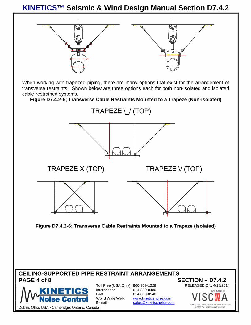
When working with trapezed piping, there are many options that exist for the arrangement oftransverse restraints. Shown below are three options each for both non-isolated and isolatedcable-restrained systems.
Figure D7.4.2-5; Transverse Cable Restraints Mounted to a Trapeze (Non-isolated)
Figure D7.4.2-6; Transverse Cable Restraints Mounted to a Trapeze (Isolated)
KINETICS™ Seismic & Wind Design Manual Section D7.4.2
CEILING-SUPPORTED PIPE RESTRAINT ARRANGEMENTSPAGE 5 of 8 SECTION – D7.4.2
Toll Free (USA Only): 800-959-1229 RELEASED ON: 4/18/2014International: 614-889-0480FAX 614-889-0540World Wide Web: www.kineticsnoise.comE-mail: [email protected]
Dublin, Ohio, USA Cambridge, Ontario, Canada
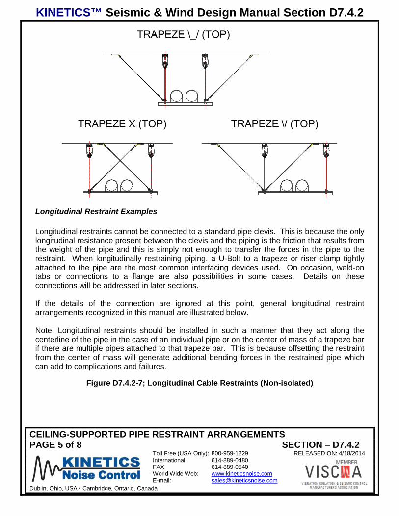
Longitudinal Restraint Examples
Longitudinal restraints cannot be connected to a standard pipe clevis. This is because the onlylongitudinal resistance present between the clevis and the piping is the friction that results fromthe weight of the pipe and this is simply not enough to transfer the forces in the pipe to therestraint. When longitudinally restraining piping, a U-Bolt to a trapeze or riser clamp tightlyattached to the pipe are the most common interfacing devices used. On occasion, weld-ontabs or connections to a flange are also possibilities in some cases. Details on theseconnections will be addressed in later sections.
If the details of the connection are ignored at this point, general longitudinal restraintarrangements recognized in this manual are illustrated below.
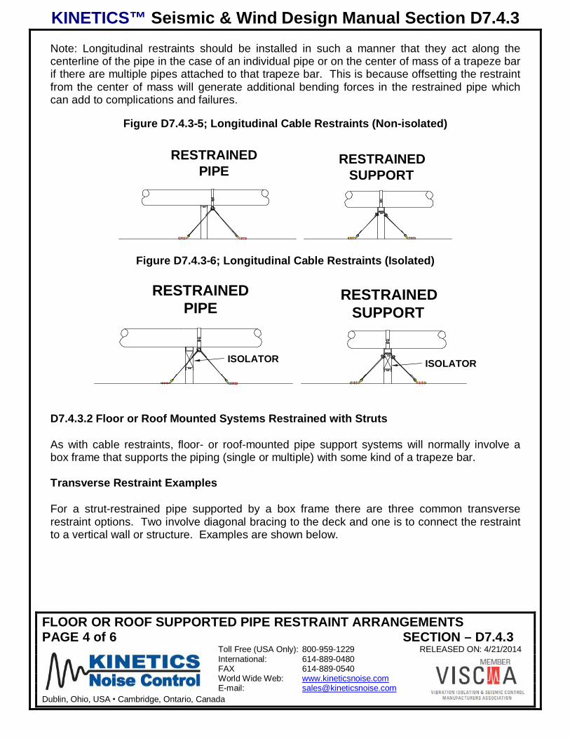
Note: Longitudinal restraints should be installed in such a manner that they act along thecenterline of the pipe in the case of an individual pipe or on the center of mass of a trapeze barif there are multiple pipes attached to that trapeze bar. This is because offsetting the restraintfrom the center of mass will generate additional bending forces in the restrained pipe whichcan add to complications and failures.
Figure D7.4.2-7; Longitudinal Cable Restraints (Non-isolated)

KINETICS™ Seismic & Wind Design Manual Section D7.4.2
CEILING-SUPPORTED PIPE RESTRAINT ARRANGEMENTSPAGE 6 of 8 SECTION – D7.4.2
Toll Free (USA Only): 800-959-1229 RELEASED ON: 4/18/2014International: 614-889-0480FAX 614-889-0540World Wide Web: www.kineticsnoise.comE-mail: [email protected]
Dublin, Ohio, USA Cambridge, Ontario, Canada
Figure D7.4.2-8; Longitudinal Cable Restraints (Isolated)

KINETICS™ Seismic & Wind Design Manual Section D7.4.2
CEILING-SUPPORTED PIPE RESTRAINT ARRANGEMENTSPAGE 7 of 8 SECTION – D7.4.2
Toll Free (USA Only): 800-959-1229 RELEASED ON: 4/18/2014International: 614-889-0480FAX 614-889-0540World Wide Web: www.kineticsnoise.comE-mail: [email protected]
Dublin, Ohio, USA Cambridge, Ontario, Canada
Hanging Systems Restrained with Struts
It is recommended that struts not be used to restrain isolated piping systems. Struts willgenerate hard connections between the piping and structure and will greatly reduce theefficiency of the isolation system. Having said that, in some special situations it may bepossible to design restraint struts with integral isolation elements, but this is tedious and shouldbe avoided unless drastic measures are required.
As with cable restraints, hanging systems may include supports for single pipes or multiplepipes. Single pipes can be supported using clevis hangers, but multiple pipes are normallysupported on trapeze bars.
Transverse Restraint Examples
For a strut-restrained pipe supported by a hanger clevis there are two common options. Oneis to connect the restraint to the clevis bolt and the other is to connect the restraint to thehanger rod. These are shown below. A third option of fitting a heavy duty riser clamp adjacentto the clevis bracket and attaching the strut to it is viable as well.
Figure D7.4.2-9; Typical Transverse Restraint Strut Arrangements for Clevis-SupportedPipe
Shown below are 3 options for trapeze-supported piping. All are equivalent.
Figure D7.4.2-10; 3 Arrangements for Transversely Restrained Trapezes with Struts
KINETICS™ Seismic & Wind Design Manual Section D7.4.2
CEILING-SUPPORTED PIPE RESTRAINT ARRANGEMENTSPAGE 8 of 8 SECTION – D7.4.2
Toll Free (USA Only): 800-959-1229 RELEASED ON: 4/18/2014International: 614-889-0480FAX 614-889-0540World Wide Web: www.kineticsnoise.comE-mail: [email protected]
Dublin, Ohio, USA Cambridge, Ontario, Canada
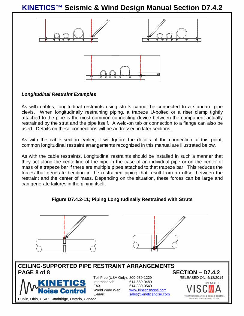
Longitudinal Restraint Examples
As with cables, longitudinal restraints using struts cannot be connected to a standard pipeclevis. When longitudinally restraining piping, a trapeze U-bolted or a riser clamp tightlyattached to the pipe is the most common connecting device between the component actuallyrestrained by the strut and the pipe itself. A weld-on tab or connection to a flange can also beused. Details on these connections will be addressed in later sections.
As with the cable section earlier, if we Ignore the details of the connection at this point,common longitudinal restraint arrangements recognized in this manual are illustrated below.
As with the cable restraints, Longitudinal restraints should be installed in such a manner thatthey act along the centerline of the pipe in the case of an individual pipe or on the center ofmass of a trapeze bar if there are multiple pipes attached to that trapeze bar. This reduces theforces that generate bending in the restrained piping that result from an offset between therestraint and the center of mass. Depending on the situation, these forces can be large andcan generate failures in the piping itself.
Figure D7.4.2-11; Piping Longitudinally Restrained with Struts

KINETICS™ Seismic & Wind Design Manual Section D7.4.3
FLOOR OR ROOF SUPPORTED PIPE RESTRAINT ARRANGEMENTSPAGE 1 of 6 SECTION – D7.4.3
Toll Free (USA Only): 800-959-1229 RELEASED ON: 4/21/2014International: 614-889-0480FAX 614-889-0540World Wide Web: www.kineticsnoise.comE-mail: [email protected]
Dublin, Ohio, USA Cambridge, Ontario, Canada
FLOOR OR ROOF SUPPORTED PIPE RESTRAINT ARRANGEMENTS
Although the basic principle of diagonal bracing is almost always used to design restraintsystems, the actual arrangements of these systems can vary significantly. Despite what lookslike substantially different designs, the design forces in the members remain the same, and thesame rules apply when sizing components. Illustrated here are many different floor- and roof-mounted restraint arrangements, all of which can be used in conjunction with the design “rules”provided in this manual.
Details of the end connections and anchorage hardware are shown in subsequent sections ofthis manual. It is assumed in this manual that the restraint component is attached to astructural element capable of resisting the design seismic load.
This manual addresses diagonal bracing oriented between horizontal and 60 degrees from thehorizontal. Angles in excess of 60 degrees to the horizontal are not permitted.
Figure D7.4.3-1; Permissible Restraint Angles
When installing restraints, Transverse restraints should be installed perpendicular ( 10degrees) to the pipe from above. Longitudinal restraints should be in line with the pipe, ( 10degrees) again as viewed from above. All restraint cables should be aligned with each other.See the sketch below.
Figure D7.4.3-2; Restraint Alignment
Transverse Restraint Longitudinal Restraint
KINETICS™ Seismic & Wind Design Manual Section D7.4.3
FLOOR OR ROOF SUPPORTED PIPE RESTRAINT ARRANGEMENTSPAGE 2 of 6 SECTION – D7.4.3
Toll Free (USA Only): 800-959-1229 RELEASED ON: 4/21/2014International: 614-889-0480FAX 614-889-0540World Wide Web: www.kineticsnoise.comE-mail: [email protected]
Dublin, Ohio, USA Cambridge, Ontario, Canada
In general, when restraining piping the component actually being restrained is the supportdevice for the pipe. This may be a pipe clevis, a heavy-duty pipe clamp, or a trapeze bar.Because the goal is to restrain the actual pipe, it is necessary that the restrained element beconnected to the pipe in such a way as to transfer the appropriate forces between the two. Forexample, if an axial restraint is installed on a trapeze bar which in turn supports a pipe that iscarried by a roller, it is obvious that the Longitudinal forces generated by the pipe cannot berestrained by the connection to the trapeze bar, and some other arrangement is needed.
When firmly connecting restraints to piping there are a few general rules that should befollowed:
1) A basic pipe clevis is not capable of restraining a pipe in the axial direction.2) If the pipe is wrapped with insulation and an axial restraint is needed, a riser clamp should
be tightly clamped to the pipe prior to wrapping it with insulation and the restraint deviceshould penetrate the insulation material.
3) If the pipe is wrapped with insulation and Transverse restraint is needed, a hardenedinsulation material should be fitted at the restraint location.
4) Piping which expands and contracts significantly should include expansion joints or loopsbetween each axial restraint component.
5) Trapeze-mounted piping should be tightly clamped to the trapeze bar.
In addition, when sizing restraint components for multiple pipes the total weight of all of therestrained piping must be considered.
D7.4.3.1 Floor or Roof mounted Systems Restrained with Cables
Floor- or roof-mounted systems may include supports for single pipes or multiple pipes.Typically, simple box frames are fabricated to support piping, whether it is a single pipe ormultiple pipes.
Transverse Restraint Examples
For a cable-restrained pipe support bracket there are four options normally encountered fornon-isolated systems and four similar arrangements for isolated systems. These options areshown below. The vertical legs of the support bracket must be sized to carry both the weightload of the supported pipes as well as the vertical component of the seismic forces. Refer toChapter D4 for more detailed information as to how to size these members.

KINETICS™ Seismic & Wind Design Manual Section D7.4.3
FLOOR OR ROOF SUPPORTED PIPE RESTRAINT ARRANGEMENTSPAGE 3 of 6 SECTION – D7.4.3
Toll Free (USA Only): 800-959-1229 RELEASED ON: 4/21/2014International: 614-889-0480FAX 614-889-0540World Wide Web: www.kineticsnoise.comE-mail: [email protected]
Dublin, Ohio, USA Cambridge, Ontario, Canada
Figure D7.4.3-3; Transverse Cable Restraints for Floor/Roof (Non-isolated)
OUTSIDE RESTRAINTSINGLE LEGRESTRAINT
INSIDE RESTRAINTX BRACED
Figure D7.4.3-4; Transverse Cable Restraints for Floor/Roof (Isolated)
OUTSIDE RESTRAINT
X BRACED INSIDE RESTRAINT
SINGLE LEGRESTRAINT
SEISMIC RATEDISOLATOR
SEISMIC RATEDISOLATOR
SEISMIC RATEDISOLATOR
SEISMIC RATEDISOLATOR
Longitudinal Restraint Examples
When longitudinally restraining piping, a U-Bolt to a trapeze or riser clamp tightly attached tothe pipe are the most common interfacing devices used. On occasion, weld-on tabs orconnections to a flange are also possibilities in some cases. Details on these connections willbe addressed in later sections.
If the details of the connection are ignored at this point, general longitudinal restraintarrangements recognized in this manual are illustrated below.
KINETICS™ Seismic & Wind Design Manual Section D7.4.3
FLOOR OR ROOF SUPPORTED PIPE RESTRAINT ARRANGEMENTSPAGE 4 of 6 SECTION – D7.4.3
Toll Free (USA Only): 800-959-1229 RELEASED ON: 4/21/2014International: 614-889-0480FAX 614-889-0540World Wide Web: www.kineticsnoise.comE-mail: [email protected]
Dublin, Ohio, USA Cambridge, Ontario, Canada
Note: Longitudinal restraints should be installed in such a manner that they act along thecenterline of the pipe in the case of an individual pipe or on the center of mass of a trapeze barif there are multiple pipes attached to that trapeze bar. This is because offsetting the restraintfrom the center of mass will generate additional bending forces in the restrained pipe whichcan add to complications and failures.
Figure D7.4.3-5; Longitudinal Cable Restraints (Non-isolated)
RESTRAINEDSUPPORT
RESTRAINEDPIPE
Figure D7.4.3-6; Longitudinal Cable Restraints (Isolated)
RESTRAINEDPIPE
RESTRAINEDSUPPORT
ISOLATORISOLATOR
D7.4.3.2 Floor or Roof Mounted Systems Restrained with Struts
As with cable restraints, floor- or roof-mounted pipe support systems will normally involve abox frame that supports the piping (single or multiple) with some kind of a trapeze bar.
Transverse Restraint Examples
For a strut-restrained pipe supported by a box frame there are three common transverserestraint options. Two involve diagonal bracing to the deck and one is to connect the restraintto a vertical wall or structure. Examples are shown below.

KINETICS™ Seismic & Wind Design Manual Section D7.4.3
FLOOR OR ROOF SUPPORTED PIPE RESTRAINT ARRANGEMENTSPAGE 5 of 6 SECTION – D7.4.3
Toll Free (USA Only): 800-959-1229 RELEASED ON: 4/21/2014International: 614-889-0480FAX 614-889-0540World Wide Web: www.kineticsnoise.comE-mail: [email protected]
Dublin, Ohio, USA Cambridge, Ontario, Canada
Figure D7.4.3-7; Typical Transverse Restraint Strut Arrangements for Pipe (Nonisolated)
SIDE STRUT DIAGONAL BRACE
ANCHOR TOSTRUCTURAL WALL
Figure D7.4.3-8; Typical Transverse Restraint Strut Arrangements for Pipe (Isolated)
SEISMIC RATEDISOLATOR
SEISMIC RATEDISOLATOR
SEISMIC RATEDISOLATOR
SIDE STRUT DIAGONAL BRACE
ANCHOR TOSTRUCTURAL WALL
Longitudinal Restraint Examples
When longitudinally restraining piping, a trapeze U-bolted or a riser clamp tightly attached tothe pipe is the most common connecting device between the component actually restrained bythe strut and the pipe itself. A weld-on tab or connection to a flange can also be used. Detailson these connections will be addressed in later sections.
Ignoring the details of the connection at this point, common longitudinal restraint arrangementsrecognized in this manual are illustrated below.
KINETICS™ Seismic & Wind Design Manual Section D7.4.3
FLOOR OR ROOF SUPPORTED PIPE RESTRAINT ARRANGEMENTSPAGE 6 of 6 SECTION – D7.4.3
Toll Free (USA Only): 800-959-1229 RELEASED ON: 4/21/2014International: 614-889-0480FAX 614-889-0540World Wide Web: www.kineticsnoise.comE-mail: [email protected]
Dublin, Ohio, USA Cambridge, Ontario, Canada
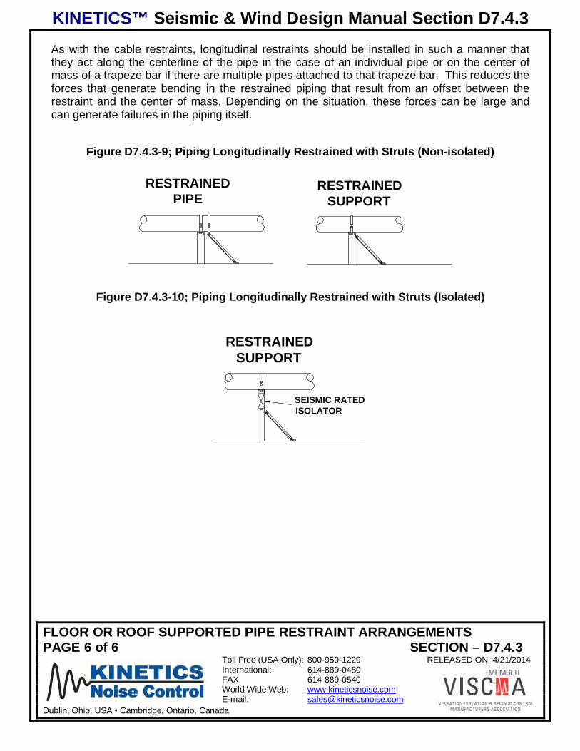
As with the cable restraints, longitudinal restraints should be installed in such a manner thatthey act along the centerline of the pipe in the case of an individual pipe or on the center ofmass of a trapeze bar if there are multiple pipes attached to that trapeze bar. This reduces theforces that generate bending in the restrained piping that result from an offset between therestraint and the center of mass. Depending on the situation, these forces can be large andcan generate failures in the piping itself.
Figure D7.4.3-9; Piping Longitudinally Restrained with Struts (Non-isolated)
RESTRAINEDSUPPORT
RESTRAINEDPIPE
Figure D7.4.3-10; Piping Longitudinally Restrained with Struts (Isolated)
RESTRAINEDSUPPORT
SEISMIC RATEDISOLATOR

KINETICS™ Seismic & Wind Design Manual Section D7.4.4
VERTICAL PIPE RUN PIPE RESTRAINT ARRANGEMENTSPAGE 1 of 4 SECTION – D7.4.4
Toll Free (USA Only): 800-959-1229 RELEASED ON: 4/21/2014International: 614-889-0480FAX 614-889-0540World Wide Web: www.kineticsnoise.comE-mail: [email protected]
Dublin, Ohio, USA Cambridge, Ontario, Canada
VERTICAL PIPE RUN RESTRAINT ARRANGEMENTS
Vertical runs of piping need to be restrained in the same manner as horizontal runs. Theanchorage provided for the riser system will normally, but not always, have enough capacity toresist the maximum longitudinal (vertical) seismic load. If anchors were selected based onsimple deadweight loads and included little or no overload capacity, the possibility exists thatthey might have to be upsized to meet the seismic requirements. Because the seismicrequirements would be low as compared to the support loads, upsizing the anchor by one stepis normally more than adequate to meet these requirements. The required capacity oftransverse (horizontal) restraints (guides) would, however, be closely linked to the seismicforces.
Cables or struts are not normally used restrain riser systems. Instead the risers resistance toseismic accelerations is controlled by special guide and anchor components. In non-seismicapplications, these parts are put in place to limit the buckling factors that are generated in thepiping by gravity factors. These are very similar to the forces generated in horizontallyoriented piping by earthquakes.
Spacing for restraints on risers must meet the same maximum span condition that applies tohorizontal runs, but in most instances the spacing used to place these items for resistance totypical buckling loads will meet this requirement.
Having indicated that the spacing will likely not be a concern based on conventional riserdesign practices the capacity of the guides can be impacted. These must be adequate towithstand the higher seismic forces. Applicable seismic forces for risers are the same as forhorizontal runs and more detail on how to determine these can be found in chapter D4.
Typical Axial Restraint Arrangements
Below are illustrations for longitudinal (vertical only) pipe restraints. A simple riser clamp canoften act as a Longitudinal restraint. It need not be attached to the structure to perform theaxial restraint function as the vertical weight loads will always be larger than the seismicallygenerated uplift loads. The same basic arrangement will work for either non-isolated or pad-isolated systems and for attachment to concrete or steel. It should be noted however thatthese components will not offer any transverse (horizontal) restraint.

KINETICS™ Seismic & Wind Design Manual Section D7.4.4
VERTICAL PIPE RUN PIPE RESTRAINT ARRANGEMENTSPAGE 2 of 4 SECTION – D7.4.4
Toll Free (USA Only): 800-959-1229 RELEASED ON: 4/21/2014International: 614-889-0480FAX 614-889-0540World Wide Web: www.kineticsnoise.comE-mail: [email protected]
Dublin, Ohio, USA Cambridge, Ontario, Canada
Figure D7.4.4-1; Concrete Supported Longitudinal Restraint for Vertical Pipe Run
PAD SUPPORTEDHEAVY DUTY RISERCLAMP
HEAVY DUTY RISERCLAMP
Figure D7.4.4-2; Steel Supported Longitudinal Restraint for Vertical Pipe Run
PAD SUPPORTEDHEAVY DUTY RISERCLAMP
HEAVY DUTY RISERCLAMP
Typical Transverse Restraint Arrangements
Pipe guides act as Transverse restraints only and have a rated force capacity that is based onloads in the horizontal axis. These components do not offer any Longitudinal restraintcapabilities.
There are two typical guide types. The first includes a component hard mounted to thestructure, a mating portion hard mounted to the pipe, and a slip fit connection between the two.This is shown below.
Figure D7.4.4-3; Supported Transverse Restraint (Guide) for Vertical Pipe Run
SEISMICALLYRATED GUIDE (KPG)
SEISMICALLYRATED GUIDE (KPG)
WELD WELD

KINETICS™ Seismic & Wind Design Manual Section D7.4.4
VERTICAL PIPE RUN PIPE RESTRAINT ARRANGEMENTSPAGE 3 of 4 SECTION – D7.4.4
Toll Free (USA Only): 800-959-1229 RELEASED ON: 4/21/2014International: 614-889-0480FAX 614-889-0540World Wide Web: www.kineticsnoise.comE-mail: [email protected]
Dublin, Ohio, USA Cambridge, Ontario, Canada
The second type is comprised of a frame with cushioned pads located on the perimeter thatbear directly against the pipe itself. This eliminates the need for a direct connection to thepipe. However, if the pipe is insulated, it does require that the insulation be adequatelyhardened or that a hard shield be provided to prevent damage to the insulation under seismicloads. Typical concrete slab and steel structural examples are shown below.
Figure D7.4.4-4; Perimeter Type Transverse Restraint (Guide) for Vertical Pipe Run
WELD
4 SINGLE AXIS PADSON HEAVY ANGLEFRAME WELDED TOSTRUCTURE
4 SINGLE AXIS PADSON HEAVY ANGLEFRAME ANCHOREDTO STRUCTURE
Combined Lateral and Axial Restraints
In addition to the above details showing independent axial and lateral restraint devices, thereare several devices used in vertical runs of pipe that offer both of these together. Anchors forriser systems are the first of these and several types are illustrated below:
Figure D7.4.4-5; Simple Hard-mounted Riser Clamp
HEAVY DUTY RISERCLAMP ANCHOREDTO FLOOR
HEAVY DUTY RISERCLAMP BOLTED ORWELDED TO BEAM
WELD WELD

KINETICS™ Seismic & Wind Design Manual Section D7.4.4
VERTICAL PIPE RUN PIPE RESTRAINT ARRANGEMENTSPAGE 4 of 4 SECTION – D7.4.4
Toll Free (USA Only): 800-959-1229 RELEASED ON: 4/21/2014International: 614-889-0480FAX 614-889-0540World Wide Web: www.kineticsnoise.comE-mail: [email protected]
Dublin, Ohio, USA Cambridge, Ontario, Canada
Figure D7.4.4-6; Simple Hard-mounted Riser Clamp
PAD SUPPORTEDHEAVY DUTY RISERCLAMP ANCHOREDTO FLOOR
PAD SUPPORTEDHEAVY DUTY RISERCLAMP BOLTEDTO FLOOR
WELDWELD
Figure D7.4.4-7; Riser Mounted on Cushioned Rated Anchor
SEISMICALLYRATED ANCHOR (KPA)
SEISMICALLYRATED ANCHOR (KPA)
WELD WELD
The final combination axial and lateral restraint is a seismically rated, floor-supported isolator.
Figure D7.4.4-8; Riser Piping Mounted on Floor-Mounted Seismically-Rated Isolator
SEISMICALLYRATED ISOLATOR
SEISMICALLYRATED ISOLATOR

KINETICS™ Seismic & Wind Design Manual Section D7.4.5
LONGITUDINAL RESTRAINT OF STEAM OR HOT WATER PIPINGPAGE 1 of 2 SECTION – D7.4.5
Toll Free (USA Only): 800-959-1229 RELEASED ON: 4/21/2014International: 614-889-0480FAX 614-889-0540World Wide Web: www.kineticsnoise.comE-mail: [email protected]
Dublin, Ohio, USA Cambridge, Ontario, Canada
LONGITUDINAL RESTRAINT OF STEAM OR HOT WATER PIPING
The Axial Restraint of Steam Piping raises important design configuration issues. As the pipelength grows with the temperature, the use of more than one restraint on any individual run willresist this growth and will either cause the pipe to buckle or will result in the failure of therestraint. This is unacceptable.
Figure D7.4.5-1; Limit Longitudinal Restraints to 1 per Run
For short runs, a single Longitudinal restraint should be used and caution should be exercisedto ensure that if restraints are fitted at the junction points of different runs, they do not fall atboth ends of the same run. Caution should also be exercised to be sure that there is adequatelength between corners and the first Transverse restraint on a run to allow for the growth thatcan occur on the adjacent run.
Figure D7.4.5-2; Ensure Adequate Corner Spacing when Fitting Transverse restraints toAllow Growth in Adjacent Run
For long runs that require more than 1 Longitudinal Restraint, a device must be fitted into therun to absorb expansions and contractions between the restraint locations. This can take theform of an expansion loop or an expansion compensator as illustrated below.
If an expansion loop is fitted, the middle leg of the loop requires Longitudinal restraint as well.Because this restricts its movement, some caution must be used to ensure that the legs oneach side of the loop are adequate to absorb the expansion for their respective runs. If the
LongitudinalRestraint

KINETICS™ Seismic & Wind Design Manual Section D7.4.5
LONGITUDINAL RESTRAINT OF STEAM OR HOT WATER PIPINGPAGE 2 of 2 SECTION – D7.4.5
Toll Free (USA Only): 800-959-1229 RELEASED ON: 4/21/2014International: 614-889-0480FAX 614-889-0540World Wide Web: www.kineticsnoise.comE-mail: [email protected]
Dublin, Ohio, USA Cambridge, Ontario, Canada
distance between the loop and the restraints on adjacent runs is approximately the same thesystem will be balanced and both legs will bend about the same. If the dimensions to the axialrestraints vary significantly, the distortion of the two different legs will vary from one another indirect proportion and this should be addressed in design. Kinetics is not responsible for thedesign of these loops.
Figure D7.4.5-2; Longitudinal Restraints on Expansion Loops
LongitudinalRestraint
LongitudinalRestraint
KINETICS™ Seismic & Wind Design Manual Section D7.5.1
TRANSFERRING FORCES (PIPING RESTRAINTS)PAGE 1 of 2 SECTION – D7.5.1
Toll Free (USA Only): 800-959-1229 RELEASED ON: 4/21/2014International: 614-889-0480FAX 614-889-0540World Wide Web: www.kineticsnoise.comE-mail: [email protected]
Dublin, Ohio, USA Cambridge, Ontario, Canada
TRANSFERRING FORCES (PIPING RESTRAINTS)
In order for a restraint system to do its job, all elements of the connections need to be sizedand installed properly. Because of the large variety and quantity of interfacing conditions inany given installation, piping, duct, and electrical distribution systems are particularly prone toproblems in this area.
The next several sections of this manual will deal with specific components used to clampcable ends together, or anchor cables or struts to steel members, wood members, andconcrete or masonry. There are several types of connections used for each of theseconditions, and each type of connection requires some degree of care and understanding toachieve full capacity.
There are a few general rules that apply when adding restraints to systems. These are listedbelow along with a few comments meant to provide a basic understanding or rationale.
1) Friction generally cannot be counted on when dealing with dynamic, seismic loadconditions. Connections, with the following exceptions, should be positive in nature and notrequire friction to ensure their continued long-term operation.
Exceptions:A) Cable end connections (swaged ends, U-bolts, QuakeLocs can be used with
appropriate installation procedures).
B)Toothed strut nuts used in conjunction with a purpose-designed strut material (Unistrut,for example). (Rationale: Permitted friction connections have been well researchedand deal with a narrow range of applications. In addition, once properly tightened, thecomponents are such that the likelihood of their coming loose as a result of seismicload conditions is very low.)
2) Anchors used for the support of overhead equipment cannot also be used for theanchorage of seismic restraints. (Rationale: The loads used to size hanger rods andanchors are based on the weight loads generated by the piping system. Seismic forcescan increase the tensile loads significantly, and the combination of loads can cause theanchorage to fail.)
3) Anchors to concrete must comply with minimum edge distance, spacing and slab thicknessrequirements. To achieve full capacity ratings they must further not be installed into asurface containing significant tensile forces. (Rationale: All anchorage must be incompliance with ICC allowables for seismic applications. Unless otherwise noted, it isassumed that connections are not made to the underside of structural concrete beams.)
4) Screws attached to wood must comply with minimum edge distance, spacing andembedment requirements, and must further not be embedded into the end grain of the

KINETICS™ Seismic & Wind Design Manual Section D7.5.1
TRANSFERRING FORCES (PIPING RESTRAINTS)PAGE 2 of 2 SECTION – D7.5.1
Toll Free (USA Only): 800-959-1229 RELEASED ON: 4/21/2014International: 614-889-0480FAX 614-889-0540World Wide Web: www.kineticsnoise.comE-mail: [email protected]
Dublin, Ohio, USA Cambridge, Ontario, Canada
wooden member. (Rationale: All wood anchorage must be in compliance with NDSallowables for seismic applications. Full capacity can only be achieved with adequateembedment, end, and edge distances into the side grain of structural wood members.)
5) Connections that have the potential to expose open bar joist chords to significant lateralloads perpendicular to their primary axis are not permitted. (Rationale: Open joists arenotoriously weak at 90 degrees to their long axis. They are not designed to take loads inthis direction, particularly on the lower cord. Even light lateral loads can generate bucklingand quickly cause catastrophic failure.)
6) Connections that have the potential to generate significant lateral loads on the weak axis ofI-beams or channels used as joists or columns are not permitted unless approved by thestructural engineer of record. (Rationale: Floor or roof support beams are significantlyweaker in their minor axis than in their major axis. While they can, under some conditions,withstand some lateral loads, the engineer of record should be consulted to ensure thatcapacity exists on particular members to withstand the anticipated loads. If these loads areexceeded, catastrophic failures can quickly result.)
7) Holes should not be added to key structural members without prior authorization from theengineer of record. (Rationale: The addition of holes, particularly in flanges, can greatlyreduce the structural capacity.
8) The pipe-to-pipe connection can become a critical factor in evaluating the performance ofthe system. Unless otherwise informed, Kinetics Noise Control assumes connections to beof “medium” deformability as defined by the design code. This is generally appropriate forsteel or welded fittings, brazed connections. The use of groove-type coupling, cast ironcouplings, glass lined pipe, Plastic or other non-standard materials will impact this andmust be addressed during the design stage. (Rationale: While generic data is available forsome of these materials, it is not for groove-type or other specialty couplings and thespecifying agency, prior selecting this type of hardware, must obtain the approval of thecoupling manufacturer for its use in a seismic application.)

KINETICS™ Seismic & Wind Design Manual Section D7.5.5
NON-MOMENT GENERATING CONNECTIONSPAGE 1 of 1 SECTION – D7.5.5
Toll Free (USA Only): 800-959-1229 RELEASED ON: 4/21/2014International: 614-889-0480FAX 614-889-0540World Wide Web: www.kineticsnoise.comE-mail: [email protected]
Dublin, Ohio, USA Cambridge, Ontario, Canada
NON-MOMENT GENERATING CONNECTIONS
The IBC codes allow the omission of seismic restraints for piping, conduit and ductwork runsunder many conditions without regard to size but that are located within 12” of the structure.Refer also to section D2 of this manual for specific exemptions by code version. This figure is6” for fire sprinkler piping. In order to qualify for this, the following parameters must be met:
1) The length of all supports on the run measuring from the top anchorage point to theconnection point to the trapeze bar or the top of a singly supported pipe or conduit run mustnot exceed 12” (6” for fire piping).2) Unrestrained free travel of the supported system must be such that over the course of itsmovement, contact is not made with any other system, component or structural element thatcan result in damage to either the supported system or the object it hit.3) The top connection to the structure must include a Non-Moment generating connection toprevent damage to the hanger rod or support strap.
A Non-Moment generating connection is any device that would allow a free flexing action ofthe hanger rod or support strap for an unlimited number of cycles without its being weakened.This motion must be permitted in any direction.
Shown below are typical examples of acceptable Non-Moment generating connections. Anyother device that allows the same freedom of motion is equally acceptable.
A hanger rod rigidly embedded into the underside of a concrete structural slab is not.
Figure D7.5.5-1; Non-Moment Generating Connections
CLEARANCE
ISOLATOR
CHAIN
SHEETMETALSTRAP

KINETICS™ Seismic & Wind Design Manual Section D7.6
CONNECTION OPTIONS FOR AWKWARD SITUATIONSPAGE 1 of 5 SECTION – D7.6
Toll Free (USA Only): 800-959-1229 RELEASED ON: 4/23/2014International: 614-889-0480FAX 614-889-0540World Wide Web: www.kineticsnoise.comE-mail: [email protected]
Dublin, Ohio, USA Cambridge, Ontario, Canada
CONNECTION OPTIONS FOR AWKWARD SITUATIONSAlmost every project will include some areas where installing restraints in a conventionalfashion will be difficult. This segment of the manual offers options to consider when confrontedwith various situations.
D7.6.1 Long, Narrow Hallways
Probably the most common issue in the field is how to deal with transverse restraints in long,narrow hallways. Normally there is considerable congestion in these areas and not enoughroom to angle restraints up to the ceiling structure. Often the walls are not structural and donot offer a surface to which to anchor.
When evaluating halls, the first issue is to determine if either of the walls of the hall isstructural. If either wall is structural, it offers a surface to which the restraints can often beattached. For structural walls, any relative displacement issues between the wall and thestructure supporting the pipe must be identified. The maximum permitted relativedisplacement is ¼ inch, which for most structures correspond to a difference in elevation ofapproximately 2 feet (see also the Structural Attachment Section of this chapter).
Assuming the wall meets both of the above requirements, a transverse restraint can be runeither directly over to the wall or up at a slight angle to the wall. Normally this would be donewith a strut as shown below.
Figure D7.6-1; Trapeze-Mounted Piping Restrained to Structural Wall or Column with a Horizontal Strut

KINETICS™ Seismic & Wind Design Manual Section D7.6
CONNECTION OPTIONS FOR AWKWARD SITUATIONSPAGE 2 of 5 SECTION – D7.6
Toll Free (USA Only): 800-959-1229 RELEASED ON: 4/23/2014International: 614-889-0480FAX 614-889-0540World Wide Web: www.kineticsnoise.comE-mail: [email protected]
Dublin, Ohio, USA Cambridge, Ontario, Canada
Figure D7.6-2; Trapeze-Supported Piping Restrained to Structural Wall or Column with an Sloping Strut
Figure D7.6-3; Clevis-Supported Piping Restrained to Structural Wall or Column
For the case where there are no nearby structural connection points or where the nearbystructural elements are not suitable, there are several options that can be considered.
The first option is to restrain to the ceiling using “X” bracing or a diagonal strut.
Figure D7.6-4; “X” or Diagonally Braced Restraint Arrangement

KINETICS™ Seismic & Wind Design Manual Section D7.6
CONNECTION OPTIONS FOR AWKWARD SITUATIONSPAGE 3 of 5 SECTION – D7.6
Toll Free (USA Only): 800-959-1229 RELEASED ON: 4/23/2014International: 614-889-0480FAX 614-889-0540World Wide Web: www.kineticsnoise.comE-mail: [email protected]
Dublin, Ohio, USA Cambridge, Ontario, Canada
A “K” or double “K” brace can also be used. The “K” can either be located inside the supportrods or outside the support rods, but in the case of a double “K”, both sides must be identical(either inside or outside).
Figure D7.6-5; Single and Double “K” Brace Restraint Arrangement
In cases where only non-structural walls limit access for restraint, it is frequently possible topenetrate the non-structural wall and shift the lateral restraint device to the opposite side of thewall or partition as shown here.
Figure D7.6-6; Wall Penetration Restraint (Cable)
Figure D7.6-7; Wall Penetration Restraint (Strut)

KINETICS™ Seismic & Wind Design Manual Section D7.6
CONNECTION OPTIONS FOR AWKWARD SITUATIONSPAGE 4 of 5 SECTION – D7.6
Toll Free (USA Only): 800-959-1229 RELEASED ON: 4/23/2014International: 614-889-0480FAX 614-889-0540World Wide Web: www.kineticsnoise.comE-mail: [email protected]
Dublin, Ohio, USA Cambridge, Ontario, Canada
D7.6.2 Axial Restraint Strut at a Dogleg
This arrangement is often a convenient way to connect an axial restraint and can occur both inthe horizontal and vertical plane. Often it will be found that when installing piping, a jog hasbeen added to a run to avoid running into a column or other structural member. Where thisoccurs, it offers an easy way to connect an axial restraint.
Figure D7.6-8; Axial Restraint Strut at a Dogleg
D7.6.3 Piggyback or Double-Tier Restraint
In congested areas, there is often a double layer of piping supported off a single trapezearrangement. It is possible under some conditions to brace one trapeze bar to the other, andthen restrain the second trapeze bar to the structure. If doing this, there are a couple ofcautions. First, the restraint capacity for the second trapeze bar must be adequate to restrainthe total load from both bars and, second, the piping must be similar in nature and ductility.
Figure D7.6-8; Piggyback or Double-Tier Restraint Arrangement

KINETICS™ Seismic & Wind Design Manual Section D7.6
CONNECTION OPTIONS FOR AWKWARD SITUATIONSPAGE 5 of 5 SECTION – D7.6
Toll Free (USA Only): 800-959-1229 RELEASED ON: 4/23/2014International: 614-889-0480FAX 614-889-0540World Wide Web: www.kineticsnoise.comE-mail: [email protected]
Dublin, Ohio, USA Cambridge, Ontario, Canada
D7.6.4 Restraints for Piping Mounted Well Below the Support Structure
This situation is not easily handled. Past history has shown, and the code is quite clear, that itis not a good idea to support the pipe from one structural element and restrain it using anotherstructural element that will undergo significantly different motions. Restraints fit in this fashionwill likely fail or cause the supports for the system that is being supported to fail. Neither ofthese outcomes is desirable..
About the only solution to this is to add a support structure for the piping that is located eitherjust above or just below the piping. The piping can then be both attached and restrained tothis structure.
The structure can be supported off the floor, off the ceiling, or from structural walls or columns.The support structure must be rigid enough to absorb all of the seismic loads, and particularlythe moments, with minimal deformation, transferring pure shear or tensile forces into thesupports.