Embed Size (px)
Citation preview

Source of Acquisition NASA Marshall Space Flight Center
Stephen L. Canfield,
Tennessee Technological University Cookeville, TN 38505 [email protected]
Kirk F. Sorensen Marshall Space Flight Center, NASA.
Huntsville, AL 35808
ABSTRACT Momentum-exchange/electrodynamic reboost (MXER) tether systems have been proposed to serve
as an "upper stage in space" [ 1,2]. A MXER tether station would boost spacecraft from low Earth orbit to a high-energy orbit quickly, like a high-thrust rocket. Then, it would slowly rebuild its orbital momentum through electrodynamic thrust, minimizing the use of propellant. One of the primary challenges in developing a momentum-exchange/electrodynamic reboost tether system as identified by the 2003 MXER Technology Assessment Group [3] is in the development of a mechanism that will enable the processes of capture, carry and release of a payload by the rotating tether as required by the MXER tether approach. This paper will present a concept that will achieve the desired goals of the capture system. This solution is presented as a multi-DOF (degree-of-freedom) capture mechanism with nearly passive operation that features matching of the capture space and expected window of capture error, efficient use of mass and nearly passive actuation during the capture process. This paper will describe the proposed capture mechanism concept and provide an evaluation of the concept through a dynamic model and experimental tests performed on a prototype article of the mechanism in a dynamically similar environment. This paper will also develop a set of rules to guide the design of such a capture mechanism based on analybcal and experimental analyses. The primary contributions of this paper will be a description of the proposed capture mechanism concept, a collection of rules to guide its design, and empirical and model information that can be used to evaluate the capability of the concept.
I. INTRODUCTION The momentum-exchange/electrodynamic reboost (MXER) tether system is proposed as a means
to harness the propellant-free thrust possible with electrodynamic space tethers [4] into a form that provides the high levels of thrust that are associated with and desirable from chemical rockets. This is performed by converting the energy produced by electrodynamic thrust into orbital energy of the tether, and then performing an exchange of momentum between the tether and payload to deliver this energy over a reasonably short duration. The transfer in energy boosts the payload to its desired higher-energy orbit while lowering the energy in the tether's orbit. The tether then restores its orbital energy through electrodynamic thrust in preparation for another launch. This procedure requires that the tether and payload rendezvous and dock for a period of time to perform the exchange of momentum and orbital energy. While the design of the system can theoretically provide exact matching of the tether and payload position and velocity at some point in their orbits, the capture process must take place over a short duration of time and must accommodate some degree of error in position and velocity. Therefore, traditional docking techniques are not appropriate [5] ; an alternative means of docking (herein referred to as capture) is required. While meeting the requirements above, it is also desired that this docking or capture procedure consume a very small amount of energy and be of a minimal mass, since any mass in the mechanism is deducted from payload capacity of the tether system.
1
https://ntrs.nasa.gov/search.jsp?R=20070001536 2018-07-11T14:53:49+00:00Z

Traditional in-space docking generally occurs with the minimum time scale of tens-of-minutes (or more) rather than the few seconds required in the MXER application [6]. A number of "short-duration" docking maneuvers have been incorporated into flight or spacecraft processes in the past. Two will briefly be described here. During the Vietnam War, extraction of downed aircraft pilots in certain situations led to a need for quick retrieval. To accommodate this, a procedure was implemented in which the pilot would don a harness attached to a small helium blimp by a cable and would deploy the blimp in a wide open area [7]. A C-130 mounted with a special forked receiving device would fly by and snag the cable in the device lifting the person out of the enemy area and reel him to safety. A second example is the in-air retrieval of spacecraft packages, for example retrieving film from the Corona capsules [8]. In these examples, the capture process consisted of trailing a "trapeze" bar with hooks to snag the capsulek parachute using a C-130 aircraft to rendezvous and arrest the spacecraft package. This method relied on some general lmowledge of position and the skill of pilots flying the aircraft. While these two examples demonstrate the need at times to perform rendezvous over a short duration, these systems vary greatly from that described here in that they involved capture of systems with non- matching velocities and give little consideration to conserving energy in the system. Therefore, a new capture mechanism appropriate for the MXER tether system is needed to enable the processes of capture, carry and release of a payload. This paper will describe a capture mechanism concept proposed by the authors that operates in a nearly passive fashion and is capable of accommodating errors in position and velocity while minimizing weight, undesirable dynamics, and energy losses. A series of design rules are developed for this concept that will guide the development of a fiture capture mechanism. Finally, a 1/10 scale prototype of this mechanism was fabricated and tested in a dynamically similar environment leading to initial validation of a dynamic model to be used in future design and preliminary evaluation of the suitability of the proposed capture system..
The remainder of the paper proceeds as follows. Section 2 will describe the capture mechanism concept. Section 3 will present a series of analytical rules for design of the capture mechanism while section 4 will describe the dynamic model that is developed for this concept to be used as an additional design tool. Section 5 describes the experimental testing of a prototype mechanism and comparisons with corresponding data from the dynamic model. The paper closes with results and conclusions in section 6 .
2. MXER TETHER CAPTURE MECHANISM CONCEPT 2.1 Background
Before describing the capture mechanism concept, a brief description of the kinematic behavior of the tether and payload during a short period of time spanning the rendezvous event is in order. Consider first the tether traveling along an elliptical orbit in the equatorial plane. The tether is rotating in a prograde fashion in this plane, such that the tip of the tether could be considered to travel along a cycloidal path along this elliptical orbit (Figure 1). Similarly, the payload is placed into a circular orbit within the equatorial plane. If Ztip defines the tether length from the center of mass to the capture end of the tether, then the tether orbit is defined such that,
where rp,6 rp are the perigee and orbital radius of the tether and payload respectively, Vp# vp are the velocity at perigee and orbital velocity of the tether and payload respectively, and 6 is the nominal rotation of the tether relative to a frame orbiting with the tether center of mass. Based on these assignments, the tether tip and payload meet at the tether perigee at the same location with the same velocity, instantaneously. As an aside, the orbits can also be defined such that the tether orbit is an integer multiple of the payload orbit.
The path of an ideal tether tip can be plotted relative to the payload for a short period of time around rendezvous as shown in fig. 2. In practice, the tether motion can not be so accurately modeled, due to the large number of variable or unknown factors affecting the dynamic behavior of both the tether
2

and payload, which therefore create potential error in position and velocity alignment that must be accounted for by the tether capture mechanism. An effort has been made to quanti@ this potential error in the form of an error-window described as an error ellipse [SI. This error ellipse considered potential error in tether dynamic behavior as a function of unlcnown material and environmental parameters. The analysis was performed using a Monte-Carlo simulation with variability in inputs defined Eom available data or reasonable estimates. The results suggest that an error window can be reasonably represented as an ellipse with the major axis aligned with the tether at time of capture, minor axis lying along the tether orbit tangential, and a major axis to minor axis ratio of approximately 1O:l. This ellipse is shown schematically on fig. 2.
Figure I : Procession of mechanism thru capture process.
3
Figure 2: Schematic of the relative motion and error window.
Beyond these primary kinematic design requirements considerations of mass, cost, simplicity, etc. were also included in the design.
2.2 Concept Descriution The proposed MXER tether capture mechanism is shown schematicalIy in Fig. 3. The planar part
of the mechanism consists of eight links (four slender beams called spreader bars and four corner nodes) connected with eight prismatic joints. The spreader bars are arranged to form a quadrilateral with two orthogonal prismatic joints located at each corner. Due to this symmetric, four-sided arrangement,
3

i I
Figure 5: Series of stages during capture process.
3. DESIGN RULES FOR THE CAPTURE MECHANISM CONCEPT
There are a number of practical issues that arise from the discussion of the proposed capture mechanism concept and yield a set of rules to guide its design. These design rules will be derived to cover the primary kinematic dimensional properties of the Quadtrap and some of the basic flexural stifkess properties. First, symmetry and orthogonality of the Quadtrap are implied based on an assumed in- and out-of-plane symmetry of the error ellipse to be satisfied by this mechanism. Further, the spreader-bar length will be defined to match the minor axis of the error ellipse as
where b is the minor axis of the error ellipse (fig. 2). The major axis of the error ellipse defines bounds for the angle 6 and can be determined from the required 10: 1 error ellipse axis ratio and fig. 3 as,
The next dimensional parameter, L, the length of the cable attaching a comer node to the end of the tether is determined Erom a consideration of Quadtrap mobility and required actuation time. Due to symmetry and orthogonality, the planar part of the mechanism has six degrees-of-Ereedom @OF). Four are idle translations of the four spreader bars which are limited with mechanical stops at each end. The remaining two DOF define the area spanned by the trap. These two DOF are actuated fiom the open to closed configuration due to inertial effects (the capture mechanism will experience approximately 2 g acceleration directed upward along the axis of the tether due to tether rotation relative to its orbital fiame in current MXER tether designs). Due to this inertially-driven closing, the mechanism has been termed nearly-passive. The closing process must occur over the period of five seconds or less based on tether motion through the proposed error window. By assuming a representative model of a symmetric comer as a simple pendulum, an approximation of the actuation time for the Quadtrap can be described as a function of cable length, L. Neglecting ffictional effects and assuming steady acceleration, the period for a pendulum for large angles is given by the following relation [ 101,
I , > b (3)
e2cot-l(io.JZ). (4)
yielding,
2
L l g -- (SA] 5
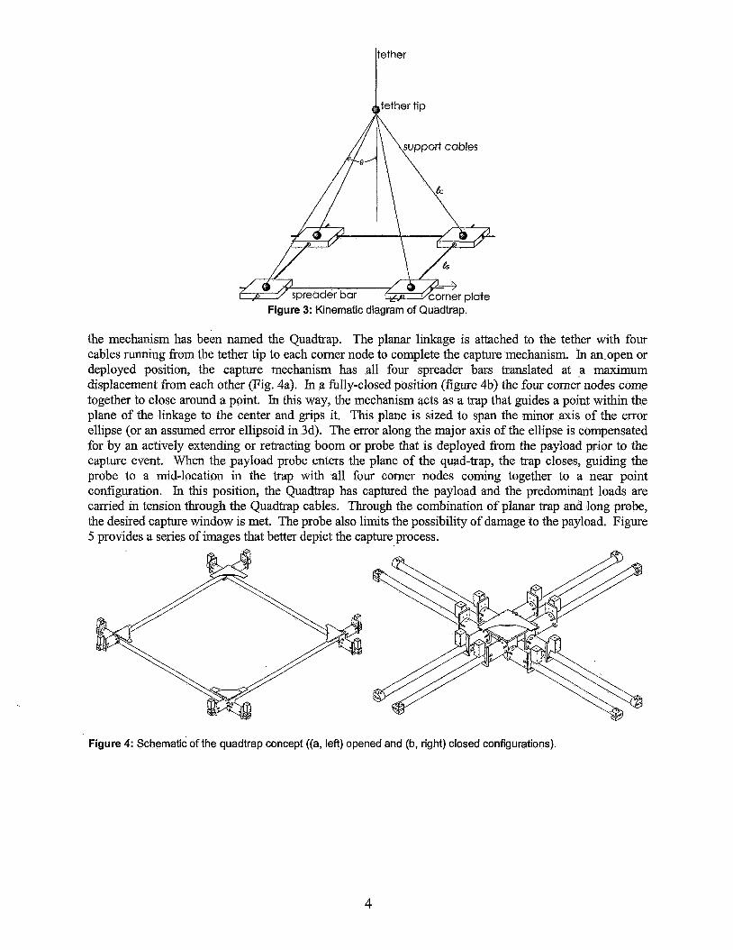
Figure 3: Kinematic diagram of Quadtrap.
the mechanism has been named the Quadtrap. The planar linkage is attached to the tether with four cables running from the tether tip to each corner node to complete the capture mechanism. In anopen or deployed position, the capture mechanism has all four spreader bars translated at a maximum displacement from each other (Fig. 4a). In a fully-closed position (figure 4b) the four comer nodes come together to close around a point. In this way, the mechanism acts as a trap that guides a point within the plane of the linkage to the center and grips it. This plane is sized to span the minor axis of the error ellipse (or an assumed error ellipsoid in 3d). The error along the major axis of the ellipse is compensated for by an actively extending or retracting boom or probe that is deployed from the payload prior to the capture event. When the payload probe enters the plane of the quad-trap, the trap closes, guiding the probe to a mid-location in the trap with all four corner nodes corning together to a near point configuration. In this position, the Quadtrap has captured the payload and the predominant loads are carried in tension through the Quadtrap cables. Through the combination of planar trap and long probe, the desired capture window is met. The probe also limits the possibility of damage to the payload. Figure 5 provides a series of images that better depict the capture process.
Figure 4: Schematic of the quadtrap concept ((a, left) opened and (b, right) closed configurations).
4
where K denotes the elliptic integral, the factor 2K/z 5 1.002 for 0 5 10” and t is the maximum allowed closure time. Tabulated values for elliptic integrals are available in standard references. Together, Eqs. 4 and 6 specify the region in which L can be selected. For example, if a closure time of 3.5 seconds is specified (period of 14 seconds) and g is replaced by the local acceleration of 19.8 m/s2 (2g) then L is found to be equal or less than 100 meters. Opening the Quadtrap requires an external actuation souice, but may occur over a much longer period of time with minimal power requirements. Note that the mass of the elements within the Quadtrap do not affect the kinematic dimensional design rules (Eqs., 3,4, and 6).
Design rules on the structural properties of the spreader bars and cable elements forming the Quadtrap are presented next. Two aspects will be considered in formulating design guides for the spreader bars, buckling and dynamic behavior. Prior to capture, the Quadtrap must be held in an open position with mechanical latches; small actuators are required to release these latches. The reaction force needed to maintain the open configuration is calculated by a summation of forces on the block and is found to b e e m g tan(@) where rn is the equivalent mass at the corner consisting of the corner node plus portions of the spreader-bars. Comparing this load to a critical buckling load based on a simple approximation of Euler buckling [ 1 11 for pinned ends yields a design limit for the spreader-bar flexural stiffness as,
where E, Iand I, are the modulus, moment of inertia and length of the spreader-bar respectively and n, is a factor of safety. Pinned ends are assumed here due to the fact that the inertia of the comer nodes is small. Equation 6 then represents a design rule for determining the flexural stifhess of the spreader bars based on buckling (note that a limit on cross-sectional area could be defined by requirements on stress or axial deflection, which are assumed to be insignificant relative to buckling limits). Considering dynamic behavior, it is desired that the Quadtrap and the spreader bars not be excited by the lowest-frequency tether modes. Considering pinned-end conditions for the spreader bars, limits on the natural frequency of the spreader-bars [12] can be used to define a range for their properties as
with n=I the first mode of the spreader-bar, E, I, p, A properties of the spread-bars, Ol,fethU the first frequency of the first tether mode (approx. 10s in current MXER tether design,s) and k a multiplication factor. Equations 7a and 7b need to be considered simultaneously to define limits on the spreader bar area, mass and stiffness properties.
Finally, design rules on cables connecting the Quadtrap to the tether are defined through strength and deflection limits, and dynamic requirements which place the natural fi-equency of the cables (given in Eq. 8) well above the fundamental tether frequency also used in Eq. 7b. The natural frequency of the cable is given by Timoshenko and Young [13] as in Eq. 8 as,
with co, the natural frequency of the Quadtrap support cables, E, p2 A, and I, modulus, mass per length, area and length properties of the cables, and p defined as,
(9)
with rn the equivalent mass of one quarter of the Quadtrap mechanism as in Eq. 7a.
A few practical observations of the proposed capture mechanism are made. The design offers the following significant features; 1) it matches the error window suggested for the MXER tether, 2) it
6

efficiently transfers forces from the payload to the tether through cables, allowing an efficient design in terms of mass, and 3) it requires small amounts of power to operate with an entirely passive operation for the closing process. The proposed design does not currently consider the details in the transfer of forces from the capture mechanism to the probe and payload beyond a simplistic series of discrete flanges on the payload probe that will catch on the closing comer nodes of the Quadtrap. Further, the details of the payload probe are also not considered. Nor are the options of the MXER tether length being dynamically varied prior to capture as a “fine adjustment” to the capture timing and placement. The closing process is proposed to be automated through a ranging device located on the capture mechanism. By determining the state of the payload relative to the capture mechanism at one or more locations, the proper time to initiate closing can be predicted (implemented on the prototype mechanism). The practical aspects of this ranging mechanism and controller for an in-space environment have not been presented however. Finally, some of the primary complications with this design are the linear bearings and exposed sliding surfaces that are required to have a fairly long lifespan, which would be a challenging problem to satis@ for the in-space environment.
4. DYNAMIC MODEL A dynamic model suitable for conducting time response simulation of the tether capture
mechanism (quadtrap) was creating using the commercial dynamic simulation software ADAMS view 12.0. The goal of this model was to provide an evaluation tool for assessing the dynamic performance of the capture mechanism at an early stage of the design process. Therefore, one of the aspects of this work is to validate the model with experimental testing on a prototype mechanism. At this early stage in the design process, the dynamic model replicates the essential kinematic and physical features of the design, without much consideration for higher-order effects. As the design of this capture mechanism progresses, it is envisioned that the fidelity of the design tool will also progress.
Description of the Adams Quadtrap model A model of the Quadtrap mechanism is created in ADAJMS following the diagram given in Fig. 3.
The dimensions of this model are based on the prototype described in section 5 which spans lm square between corner nodes in an open configuration (Is) and whose support cables are 1.6 m long (L). The model begins with a single inertially-fixed point from which a representative portion of tether extends to the tether tip, where the Quadtrap begins (note that in modeling the prototype, the tether length approaches zero to replicate lab conditions). The four cables that extend from the tether tip to the linkage are modeled as Flex (elastic) members. These Flex members are formed as a series of pinned rigid segments with inter-connecting springs to provide axial and bending stiffness. The parameters for the cable Flex members are shown in Table 1. Each cable is attached to the tether point with a spherical joint. At the opposite end are the comer nodes that are modeled as rigid block elements and are connected to the cables using spherical joints. The spreader bars are modeled as rigid cylinders (properties shown on Table I) and are connected to the corner nodes with prismatic joints. Each comer node contains two orthogonal prismatic joints whose axes intersect at the center of mass of the corner node (note that these axes are offset in the prototype). To mimic damping in the prismatic bearings, spring/damper pairs are added in parallel to the spreader bars connecting each corner node. The spring values are negligible while the damper values are 0.0 1.
The satellite payload and its probe are modeled consisting of three parts. The payload is modeled as a rigid, thin-walled cylinder with internal mass whose material properties are based on aluminum. The probe is modeled as a six-segment flex member (properties in Table I> and is connected rigidly to the payload cylinder. A small rigid cylinder is attached near the tip of the probe to represent a catch point between the payload and capture mechanism.
Contact properties are defined for the following three cases in which contact is assumed to take place: comer-node to comer-node contact, satellite probe to spreader bar contact and probe tip to comer- node contact. The contact properties include a penalty factor and a coefficient of restitution and are listed for each case on Table I. A gravitational force of 1 g was applied over the entire model in a direction along the tether axis (to mimic the laboratory test environment).
Boundary conditions for the capture mechanism consist of a pinned condition at the fixed tether point (which in this case ignores tether elastic motion to better mimic the laboratory tests) and free conditions over the remainder of the mechanism. The payload is in a free condition at the beginning of the simulation. The simulation process begins with the following initial conditions. The capture
7

mechanism is placed in its open configuration (with no constraints holding it in this open condition) and zero velocity. The payload initial position and velocity &e defined such that it will travel along a trajectory that passes the probe through the plane of the capture mechanism approximately 1 second after the start of the simulation. The simulation runs for approximately 2 seconds to completely cover the capture event. Acceleration profiles were recorded with respect to the center of mass of the members for later comparison with experimental results.
*Adam defines Penalty as the local stiffness properties between the contacting materials and Damping Ratio is defined as ratio of ,viscous damping to stiffness for the beam forces within the flex members.
le
5. EXPE NTAL TESTINGMODEL VALIDATION 5.1 Prototype Quadtrap
A prototype of the Quadtrap concept presented here was fabricated to replicate the primary components of kinematic motion and method of operation. Figure .7 shows a CAD model of the prototype while Figure 8 shows the prototype mechanism as constructed. The prototype was created as a I/lO* dimensional scale over the kinematic dimensional parameters in the system as the laboratory conditions would allow. The cross-sectional nature of the spreader-bars were one exception to this rule, they were stiffer than the design rules called for. The spreader-bars consist of hollow aluminum cylinders while the comer nodes consist of a pair of orthogonal linear bearings. While the prototype system is intended to demonstrate the inertially-driven closing process, the fact that the prototype is to be tested in a I-g environment resulted in the need to add a spring-assist to the closing force. The spring system is contained within the hollow spreader bars and matches in a linear fashion the variation of added force from a maximum at the open position to a zero assistive force at the closed position. Thus, the prototype actuation comes from a combination of gravity and assistive springs. Small actuators are built into the prototype to release the Quadtrap from its open state to begin the capture process. The prototype does not contain any type of actuator to open the device and is manually opened prior to each capture.
Figure 7: Cad model of the prototype. Figure 8: constructed prototype.
8

Due to the nature of h!EER tether system operation, a dynamically-similar environment can be readily created on earth. In this case, dynamic similarity is defmed such that the relative accelerations between the payload and capture mechanism are similar. In the MXER tether system, the payload exists in a low- earth orbit, an environment in which centripetal accelerations are balanced by gravitational forces (payload is in free-fall) while the capture mechanism experiences a predominant 2-g acceleration directed upward along the axis of the tether due to tether rotation relative to its orbital frame. Around the time of capture, the tether axis is nadir (radial passing through the center of earth). To create this similar environment in the lab, the payload is placed into a fiee-fall condition, while the tether is fixed in the lg environment. To provide a reasonable amount of time to conduct the capture experiments, the tether capture mechanism is attached at the top of a high-bay laboratory, while the payload is tossed in a parabolic trajectory that passes through the capture window space. The probe on the prototype payload is lm long which allows up to 0.9 seconds of travel time for the payload through the error window. By altering the payload trajectory, spatial errors can be simulated in the capture event. Figure 9 below shows the laboratory test environment. A capture test is conducted as follows. The capture mechanism is manually opened and latched to its open codiguration and raised to the top of the lab. The payload with attached probe is placed into the payload-launching mechanism which will toss it on a parabolic trajectory passing through the region of the capture mechanism. The launch mechanism creates the payload initial conditions for the test (payload is in a fi-ee-fall condition along a prescribed trajectory). The launch mechanism is pneumatically driven and can be adjusted to alter the trajectory of the payload. To match the predicted error window, every capture test will pass some degree of the payload probe through the plane of the capture mechanism. The capture mechanism has a series of IR ranging sensors to detect the approaching payload and will automatically release the latches that hold the trap open. Gravity and the assist spring cause the capture mechanism to close, inertia brings the payload to a completely closed condition. In a successful capture, the QI lints on the pr .obe. :S mdts .ap COI xer nc 3de
5.3 Test and Model Instrumentation The Quadtrap prototype (and correspondingly the ADAMS model) was instrumented with six
accelerometers in three-axis triplets attached to the comer nodes 1 and 3 as shown in fig. 10. The accelerometers were located as close as possible to the center of mass of opposing corner nodes and were aligned such that the z axis corresponds to the tether axis (vertical axis) while the x and y axes lie in the plane of the trap and are aligned with the spreader-bars. Four cameras were also used in instrumentation, two cameras inertially-fmed with vertical and horizontal view points, one camera attached to the payload and one camera attached to the Quadtrap.
9

Corner node 1
..’ ,/‘ ,.” Sprea$er bur 4
/ , . : I ........................ * ...... J. ................ \ ................................. ’ .................
Corner node 4
Figure 10: Schematic of quadtrap instrumentation.
Tests were conducted that observed captures occurring in all four quadrants. The primary objectives of these tests were; 1) provide data to compare with model data and anal$cal analysis of the Quadtrap, 2) serve as a test for proof-of-concept, 3) look for unexpected dynamic behavior and or phenomena in the system, and 4) lead to additional design or evaluation criteria of the system. The following section will present a series of results for one representative capture which occurs in quadrant 4.
5.4 Experimental and Model Results The results from a capture occurring in quadrant 4 are presented here. To begin this test, both the
prototype system and ADAMS model are adjusted (initial conditions modified) to cause the probe to enter the fourth quadrant of the Quadtrap. One of the inertially-fixed cameras
oad as it enters the plan
Figures 12 and 13 show the accelerometer data recorded from nodes 1 and 3
records the position of the
respectively over a duration of time spanning the capture event as well as the accelerations for these nodes drawn from the model. These results are primarily used to compare the significant events in the capture process in a qualitative fashion. Both the model and experimental results give evidence of a sequence of events that occurs as follows. Prior to initiating release of the capture mechanism (KO), the capture mechanism observes a uniform z-component of acceleration due to motion along an accelerating path (simulated in the lab by gravity). Starting at time t=O, the Quadtrap is released from its open position and the comer nodes move toward the trap center. The comer nodes momentarily move along a non-accelerating path and the z- component of acceleration goes to zero as it moves along a pendular closing path. As the rate of closure increases, the z acceleration increases due to centripetal acceleration about the attachment point to the tether. The x and y axes also observe a sinusoidal component of this acceleration (drsin(8)). At time
10

t=Q.38s, the first impact is observed between one spreader-bar and the payload boom, followed by a second impact, mdst likely with another spreader-bar 0.15s later, and ends with final closing of the Quadtrap at approximately t=Q. 58 s.
Figure 12: x,y,z accelerations for node 1. Figure 13: x,y,z accelerations for node3
Over the capture process, the capture mechanism receives a series of impulsive excitations, which excite the vibrational modes of the capture mechanism. As discussed in developing the analykal design rules in section 2.3, it is desirable that these modes occur at frequencies well above the fundamental frequency of the tether. A simple comparison of the frequency content of the excited response in the capture mechanism model is made as shown in figs. 14 and 15, by performing a Fast-Fourier Transform (FFT) on the experimental and model data for the x and z axes respectively. The FFT was performed in a numerical fashion using the “fft” function in Matlab and are based on the response of the system following one of the impulsive events of capture as shown in Figure 12. These comparisons demonstrate a primary mode at approximately 110 Hz, with the experimental system demonstrating a broader spectrum of frequency information, probably due in large part to imperfections in the physical test article.
Figure 14: Frequency content, in-plane (x) axis
1 5
B B 3 ’
T
E. .a
l o 5
Fmumcy
Figure 15: Frequency Content, capture plane-normal (z) axis
The motion of the Quadtrap mechanism during the capture process can be observed more closely by viewing the velocity and displacements of the corner nodes over the capture sequence. This position and velocity data is derived through numerical integration of the acceleration results from both the prototype system and the model. For the prototype system, the integration is performed on the acceleration data collected at a 1 kHz sampling rate, while for velocity and position can be reported directly from the model (model performs integration from equations of motion). These results are shown for the x,y,z axes of corner node one as shown in Figs. 16-17. The plotted displacement and velocity curves demonstrate a reasonable degree of agreement between the prototype system and model. Primary differences between the two results are; 1) timing of the impact events during capture, 2) mismatch in amplitudes during the later stages of the capture process, and 3) numerical instability ,of the model at the time of capture mechanism closure. Based on the level of quality and expense in the test article, these differences are considered to be reasonable and in general support the conclusion that the A D A M S model serves as a reasonable predictor of Quadtrap behavior during the capture process up to the time of mechanism
11

closure. It should be noted that this comparison is valid for the scale of the prototype tested here; extension of this validation to capture mechanism design of other scales should not be inferred &om this single point comparison.
comer 'I dsplaoermd. x y z ~ m p ~ n e n t s
-01 0 O! 0 2 0 3 0 4 0 5 0 6 0 7 0 0 1 0 2 0 3 0 4 0 5 06 bme [SI b n (51
Figure 16: Displacement of comer node 1 Figure 17: Velocity of comer node 1
Finally, the closure motion of the mechanism is considered, where closure is defined as the symmetric kinematic motion of the non-idle DOF of the mechmism (relative motion of the comer-nodes along the in-plane diagonal). This motion is derived from integration of the relative acceleration of the comer nodes in the direction of the in-plane diagonal and is shown in Figs. 18 and 19. In Fig. 18, the displacement increases to full closure at 1.414 my while the closing velocity (Figure 19) increases until impact is first made, and returns to zero at full closure. One parameter that must be satisfied by the capture mechanism is complete mechanism closure within the time period in which the payload is in the capture window. For the in-lab test system, the maximum time is 0.9 s while full closure requires a relative displacement of sqrt(2) m. The results do demonstrate first that full closure is apparent within the timeframe required. These figures also demonstrate that the model predicts a slightly faster closure time than the prototype, but is not able to accurately replicate the impact closing process. As a design rule, a necessary bound on the displacement and time period can be specified (displacement to travel 1.414 m in 0.9 s or less for the prototype) as a necessary condition for capture. The examples shown for the model and prototype demonstrate that successful capture is possible. As a design tool, the model can be used to evaluate and potentially indicate success of capture by considering different design parameters, both in the capture mechanism and in the payload and boom.
Further insight of the trap motion as shown in Figs. 18 and 19 can be used to make a more useful evaluation of the proposed capture concept in general, and a specific capture design in particular. In the proposed capture process, the capture mechanism must guide a probe extending from the payload to a central point in the trap where it is fully grasped. In the ideal capture (one in which there is no position or velocity error in the payload or tether), this capture process is trivial, and no change in momentum of the payload probe is required for the Quadkap to close. However, in the more general capture, some degree of error exists. Therefore, in operation the Quadtrap must overcome momentum in the payload probe to ensure closure and correspondingly ensure a successful capture. Figure 19 gives an indication of this impulsive (change in momentum) event during the capture process as the change in closing velocity after impact. This figure demonstrates for this experiment that sufficient momentum is available within the Quadtrap after impact to complete the closure process (i.e., closing velocity remains positive throughout). However, to guarantee successful closure, a Quadtrap design must consider the amount of momentum to be overcome in repositioning the payload probe (or in deformation of the extension boom), which is a function of bounds on velocity error and probe design. Further, while Eq. 6 gives consideration to closure time, it does not consider the requirements for momentum exchange. Such considerations are a necessary step in Quadtrap design.
12

Quadtrap closing displacemed dunrig capture 1.61 I
Figure 18: Displacement during capture Figure 19: Quadtrap closing volocity
6. CONCLUSIONS This paper has presented a capture mechanism concept to address a fundamental issue in
developing a MXER tether system as described in [2]. The proposed mechanism has been labeled the Quadtrap. As a demonstration of this concept, a proof-of-concept prototype article was designed, fabricated and tested. Tests consisted of simulations of the capture event within a dynamically similar environment with the Quadtrap accommodating errors in capture as defined by the predicted error window. Results of the tests were used to evaluate the proposed concept and to provide for comparison with a dynamic model of the system developed in ADAMS. Based on an extended period of test and evaluation, the Quadtrap capture mechanism proved surprisingly robust at performing the capture process. Capture with some degree of error (position or velocity) results in one or more impact events between the payload boom and the sides of the Quadtrap. However, these events take place between components of relatively low mass (the Quadtrap and payload boom) and therefore limit negative overall effects on the overall system. The acceleration forces observed on the Quadtrap at times were quite high, at levels up to 6-7 g, but the payload does not experience these high impulse levels. Similarly, the impact forces between the payload boom and Quadtrap spreader-bars in some cases were significant, but were well within the design criteria specified for the capture mechanism. It was observed over a significant number of tests that the system is robust to both positional error as well as timing of the release of the capture mechanism. However, proper timing of the capture mechanism can reduce the dynamic impact of the capture process making the capture mechanism more effective.
Based on the proposed capture mechanism concept, a set of quantitative rules are developed to guide the design of an appropriate Quadtrap mechanism. These parameters cover all kinematic dimensional, material and cross-sectional properties of the primary components within the system. Experimental and model results provide validation of the proposed concept for the specific design that is presented. These results can be extended to a more complete validation of the proposed concept based on consideration of momentum available to perform the capture process and close the trap. The momentum required can be defined by a range of error that the capture mechanism is capable of handling.
The capture mechanism concept as described and tested here demonstrates a number of positive features. It provides nearly passive actuation in closing, it matches the specified capture window and it provides efficient use of mass and tension structural members. It is clear after a review of this work that while a large number of practical engineering issues for routine in-space application remain, the proposed concept may provide a suitable solution to the rendezvous procedure required in MXER tether systems or other relatively fast capture applications.
BIBLIOGRAPW 1.
2.
Hoyt, R.P., “Design and Simulation of a Tether Boost Facility for LEO->GTO Payload Transport”, AIAA Paper 2000-3866,36th Joint Propulsion Conference, July 2000. K. Sorensen, 2001, “Conceptual Design and Analysis of a MXER Tether Boost Station,” AIAA 2001-3915.
13

3.
4.
5.
6. 7.
8.
9.
Sorensen, K. F., 2003, Momentum exchange Electrodynamic Reboost ( M E R ) Tether Technology Assessment Group Final Report,NAS A, httv://www.inspacepropuIsion.com/techfMXER TAG Report.pdf. retrieved Sept. 1,2006. Ortega, G. and J. M. Giron-Sierra, 1995, “Genetic algorithms for fuzzy control of automatic docking with a space station,” Proceedings of the tEEE Conference on Evolutionary Computation, ICEC, v 1, Nov. 29-Dec. 1, 1995, p 157-161. Bonometti, J. A,, 2006, “Boom Rendezvous Alternative Docking Approach,” AIM Space 2006 Conference, San Jose, CA, Sept. 19-2 1 , AIAA-2006-7239. Marshall, L. and M. Finckenor, 2004, Ypace Tethers,” Aerospace America, v 42, n 12, December 2004, pp. 92. D’Isle, Jean, “SOG VI: JPRC.” Articles, Vegsource, h~:/lwwur.vensource.co~articles/iohn4 1 .htm, May 1 1 , 2006 National Air and Space Museum, 2002, “FILM RECOVERY: ‘CATCH A FALLING STAR‘.“ Smithsonian National Air and Space Museum, http://www.nasm.si.edu/GALLERIES/GAL114/SpaceRace/sec400/sec432.hkn, Feb. 2,2006. Knight, Seth V. 2006. “Concepts and Experiments on Capture with Momentum Exchange Electrodynamic Reboost Space Tethers,” M.S. thesis, Tennessee Technological University, TN.
N Y , 1965 10. Abramowitz, M. and I. A. S t e m Handbood of Mathematical Functions, Dover Publications Inc., New York,
11. Gere, J. M. and S. Timoshenko, 1984, Mechanics of Materials, Wadswort, Inc., Belmont, CA. 12. Meirovitch, L., 1986, Elements of Vibrations, 2nd Ed., McGraw Hill, Boston, MA. 13. Timoshenko, S. and D. H. Young, 1955, Vibration Problems in Engineerin, D. Van Nostrand Company, Inc.,
Princeton, NJ.
14